Embed Size (px)
Citation preview
DEVELOPMENT OF A PERISTALTICALLY ACTUATED
DEVICE FOR THE MINIMAL INVASIVE SURGERY WITH A
HAPTIC SENSOR ARRAY
Authors: Johannes Dietrich, Siegfried Oberthür, Roman Preuß, Danja Voges
and Petra Meier
Institution: Technical University Ilmenau, Faculty of Mechanical Engineering,
Institute of Microsystems Technology, Mechatronics and Mechanics
PO 100565 – 98684 Ilmenau, Germany
e-mail: [email protected]
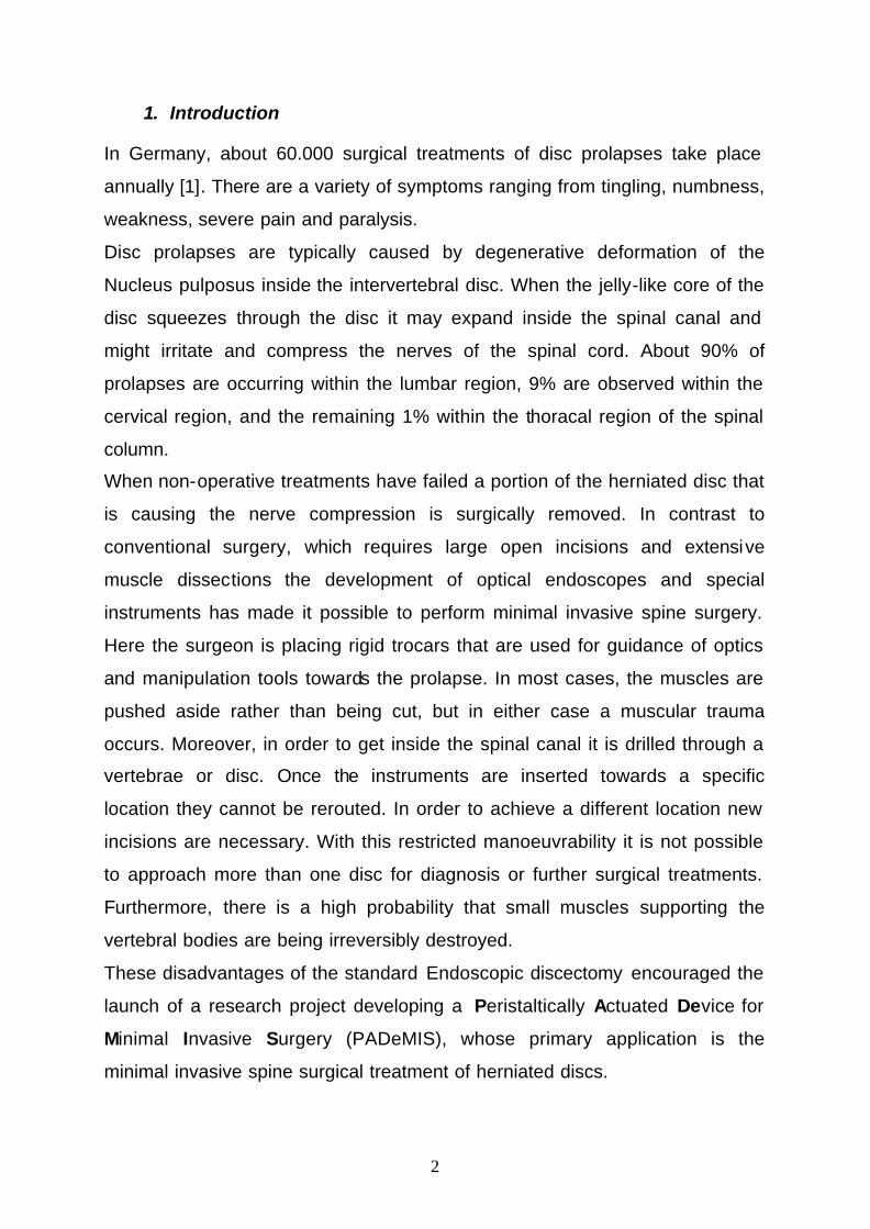
Abstract
The development of an actively moving device for minimal invasive spine
surgery is introduced. Compared to commercially available endoscopes the
device moves self actuated by peristaltic locomotion analogous to an
earthworm and it is entirely compliant. The primary application is the
endoscopic surgical treatment of herniated discs. The device is hollow inside
to provide space for the insertion of endoscopic instruments. Essential
procedures of the endeavour, i.e. examining the spinal canal, studying options
of locomotion, testing and describing the silicon rubber material utilised, Finite
Element simulation of the design, constructing a prototype facility and control
unit, are represented in detail. In addition, the perspective to integrate a haptic
sensor array is discussed.
Keywords: peristaltic, spinal canal, prolapse, silicone, haptic, hydraulic
actuation, hyper elasticity, modal analysis
2
1. Introduction
In Germany, about 60.000 surgical treatments of disc prolapses take place
annually [1]. There are a variety of symptoms ranging from tingling, numbness,
weakness, severe pain and paralysis.
Disc prolapses are typically caused by degenerative deformation of the
Nucleus pulposus inside the intervertebral disc. When the jelly-like core of the
disc squeezes through the disc it may expand inside the spinal canal and
might irritate and compress the nerves of the spinal cord. About 90% of
prolapses are occurring within the lumbar region, 9% are observed within the
cervical region, and the remaining 1% within the thoracal region of the spinal
column.
When non-operative treatments have failed a portion of the herniated disc that
is causing the nerve compression is surgically removed. In contrast to
conventional surgery, which requires large open incisions and extensive
muscle dissections the development of optical endoscopes and special
instruments has made it possible to perform minimal invasive spine surgery.
Here the surgeon is placing rigid trocars that are used for guidance of optics
and manipulation tools towards the prolapse. In most cases, the muscles are
pushed aside rather than being cut, but in either case a muscular trauma
occurs. Moreover, in order to get inside the spinal canal it is drilled through a
vertebrae or disc. Once the instruments are inserted towards a specific
location they cannot be rerouted. In order to achieve a different location new
incisions are necessary. With this restricted manoeuvrability it is not possible
to approach more than one disc for diagnosis or further surgical treatments.
Furthermore, there is a high probability that small muscles supporting the
vertebral bodies are being irreversibly destroyed.
These disadvantages of the standard Endoscopic discectomy encouraged the
launch of a research project developing a Peristaltically Actuated Device for
Minimal Invasive Surgery (PADeMIS), whose primary application is the
minimal invasive spine surgical treatment of herniated discs.
3
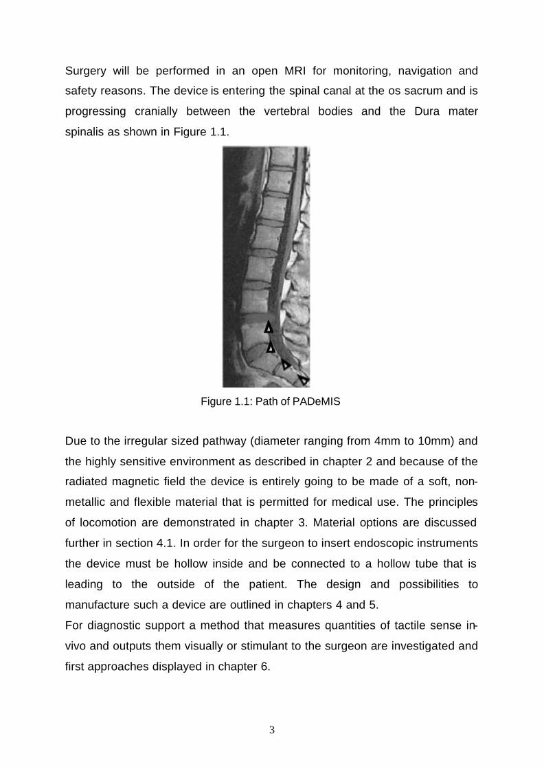
Surgery will be performed in an open MRI for monitoring, navigation and
safety reasons. The device is entering the spinal canal at the os sacrum and is
progressing cranially between the vertebral bodies and the Dura mater
spinalis as shown in Figure 1.1.
Figure 1.1: Path of PADeMIS
Due to the irregular sized pathway (diameter ranging from 4mm to 10mm) and
the highly sensitive environment as described in chapter 2 and because of the
radiated magnetic field the device is entirely going to be made of a soft, non-
metallic and flexible material that is permitted for medical use. The principles
of locomotion are demonstrated in chapter 3. Material options are discussed
further in section 4.1. In order for the surgeon to insert endoscopic instruments
the device must be hollow inside and be connected to a hollow tube that is
leading to the outside of the patient. The design and possibilities to
manufacture such a device are outlined in chapters 4 and 5.
For diagnostic support a method that measures quantities of tactile sense in-
vivo and outputs them visually or stimulant to the surgeon are investigated and
first approaches displayed in chapter 6.
4
2. Environmental conditions
The spinal canal is essentially a tunnel that runs down the entire length of the
spine from the skull to the sacrum. It is encircled by the vertebral bodies
forming the spine and it contains the spinal cord, which is an elemental part of
the central nerve system and branches of in nerve roots in the lumbar region.
2.1. Anatomical layout of the spinal canal
In an adult the spinal cord extends from the top of the Atlas (first vertebrae,
C1) to the lower border of the first lumbar vertebra. There it divides into a
bundle of many different nerve roots, which are named Cauda equina. The
spinal cord is protected by a rather stiff dural sheet, called Dura mater spinalis
(thickness ~2mm). The space between the dura and the vertebral bodies is
called epidural space. It contains ligaments (Ligamenta flava, Ligamentum
longitudinale posterius) and is filled with fat tissue and Plexus venosus
internus that provides the venous drainage for the indivi dual vertebral body.
The available minimum working space of the device being developed inside
the epidural space is limited to a diameter of 4mm and may vary up to 10mm.
[2-4].
2.2. Resistance-force Measurements
The force required for the forward motion of the device was estimated
experimentally on just euthanised pigs. A Fogarty catheter was entered from
dorsal into the lumbar region of the spinal canal between L4 and L5. The
catheter was equipped with a force sensor. After the force required to insert
the catheter cranially towards the cervical region was recorded the balloon at
the front of the catheter was inflated. The force needed to remove the catheter
was measured with respect to position and size of the balloon. The experiment
was conducted on 8 animals weighting 27-30kg. It was found that a minimum
force of 2.6N to 4.1N is necessary to move a device of 4mm in diameter.
Through those experiments it has been shown that the space available is
sufficient for such a device travelling inside the spinal canal along the Dura
mater. Because the experiments have been carried out on dead pigs it must
5
be realised that the material properties of a dead are not identical to a living
animal and secondly the vertebral column of a pig is geometrically not
identical to the human spine, which contains a distinctive curvature.
3. Locomotion
The device is travelling by peristaltic means like the crawling motion of an
earthworm. Technically, the spinal canal is a pipe filled with semifluid tissue
particles, the device must crawl past and through. Because of the natural
continuous path of the canal the device progresses towards the least resistant.
Although, no complex control is necessary, an option for steering to support
the generally given direction is considered.
3.1. Biological Inspiration
The earthworm (Annelida: Oligochaeta) moves by peristaltic locomotion.
Waves of contraction and relaxation of antagonistic muscle groups
(longitudinal and circular muscles) causes the worm to move forward. Four
pairs of bristles at each segment can be elevated for anchor the temporary
immobile segments. The body cavity is fluid-filled and partitioned into
numerous separate segments. The hydrostatic skeleton counteracts the
muscle contraction.
3.2. Schematics
The locomotion is based on a propagating wave on the surface of the moving
device. Technologically, a segmentation of the body is useful. The simplest
functional unit for a peristaltic moving device is a structure of 3 segments -
each segment allowing thickening and lengthening at the same time. Also,
any other unit of more than 3 elements is possible. In fact, a serial
arrangement of these kinds of units are conceivable. In peristaltic locomotion
a ‘step’ of an unit of n elements is achieved by n switching operations. At least
2 elements of the functional unit are controlled simultaneously. The step
6
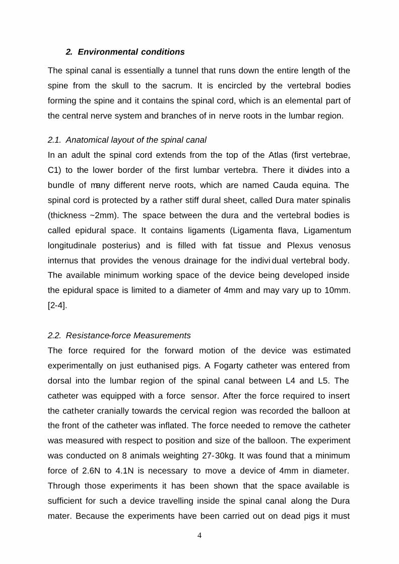
length is defined as the length difference between an inflated and deflated
element multiplied by the number of deflated elements in the functional unit.
The length of the functional can be changed. A structure with e.g. 18 elements
may be controlled by functional units of length 3, 6, 9 or 18. For PADeMIS a
sequence of 6 elements is considered due to the larger step size of one cycle
as shown in Figure 3.2.1. In order to provide sufficient dynamic stability during
locomotion, i.e. adequate contact to the surroundings, the sequence can
repeated several times.
Figure 3.2.1: Schematics of peristaltic motion.
The layout of the segments are described in section 4.2. The principle of the
peristaltic locomotion has been confirmed by a macro model that is described
in section 5.1.
7
4. Design, Simulations and Actuation of PADeMIS segments
The environmental conditions explained above and the medical application
restrict the choice of the material enormously. In addition, the controlled
deformation and stretching of individual segment are difficult to achieve and
require a precise hydraulic actuation.
4.1. Material choice
Due to the dimensions of the vertebral canal the material chosen must be
hyper elastic in order to enable a variation of the device’s outer diameter
between 4mm and 10mm. Furthermore, the material is required to be
sterilizable and it is permitted for medical use.
The large reversible stretches can be performed by rubber or rubber like
materials. For natural rubber (latex) allergic reactions are being increasingly
recognised. Nevertheless, silicone rubber (SR) has been a common material
for medical applications. Different shore hardness can be obtained with silica
filler. The SR MED49xx from Nusil is chosen for PADeMIS, where xx indicates
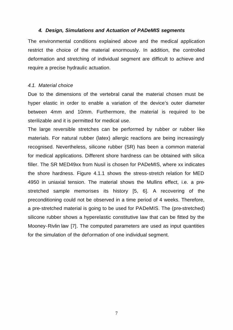
the shore hardness. Figure 4.1.1 shows the stress-stretch relation for MED
4950 in uniaxial tension. The material shows the Mullins effect, i.e. a pre-
stretched sample memorises its history [5, 6]. A recovering of the
preconditioning could not be observed in a time period of 4 weeks. Therefore,
a pre-stretched material is going to be used for PADeMIS. The (pre-stretched)
silicone rubber shows a hyperelastic constitutive law that can be fitted by the
Mooney-Rivlin law [7]. The computed parameters are used as input quantities
for the simulation of the deformation of one individual segment.
8
Figure 4.1.1: Uniaxial tension test of a silicone rubber sample with shore hardness 50. The material shows the Mullins effect.
4.2. Segment deformation
The peristaltic locomotion requires a segment to expand in diameter and to
increase in length in the axial direction simultaneously during hydraulic filling.
What is more, PADeMIS should be steerable. Therefore, the deformation
should allow an axial asymmetry. While the segments are hydraulically filled
and deformed the diameter of the internal hollow tunnel of the device must be
maintained at 2mm.
For the design and evaluation process the Finite element software ANSYS is
used. The deformation of the silicone rubber is simulated with the Hyper58
element in a nonlinear calculation.
9
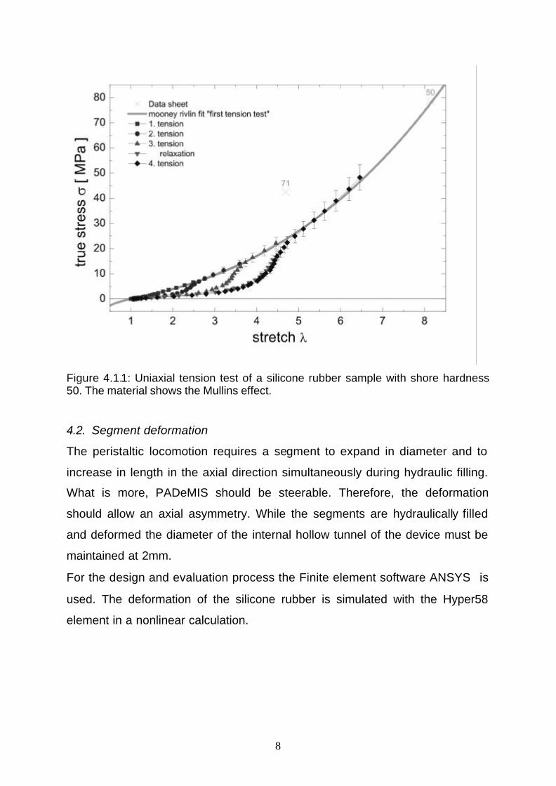
Figure 4.2.1 shows a segment of PADeMIS containing 4 cushions simulated
with the material properties fitted from the uniaxial tension test of pre-stretched
Nusil Med 4950. In this simulation the segment is deformed by nearly obeying
the conditions stated above.
Figure 4.2.1: Radial Translation of the silicone sheets of one PADeMIS segment at pressure p=0.177bar.
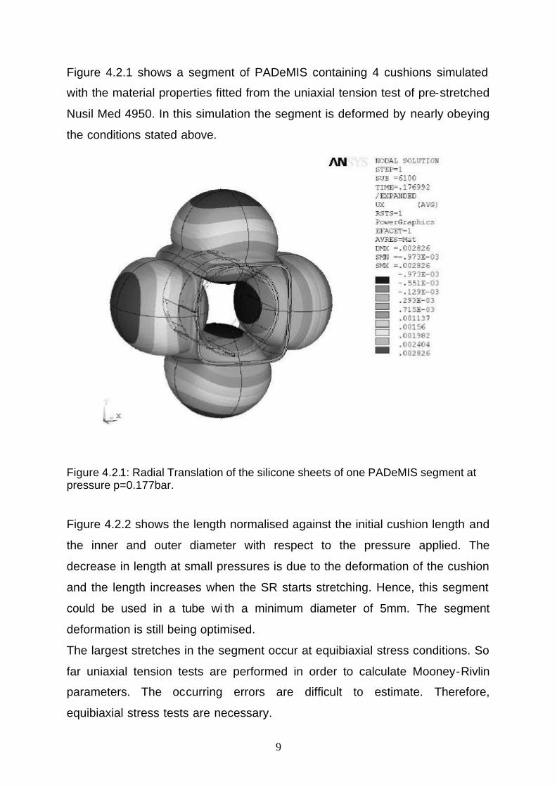
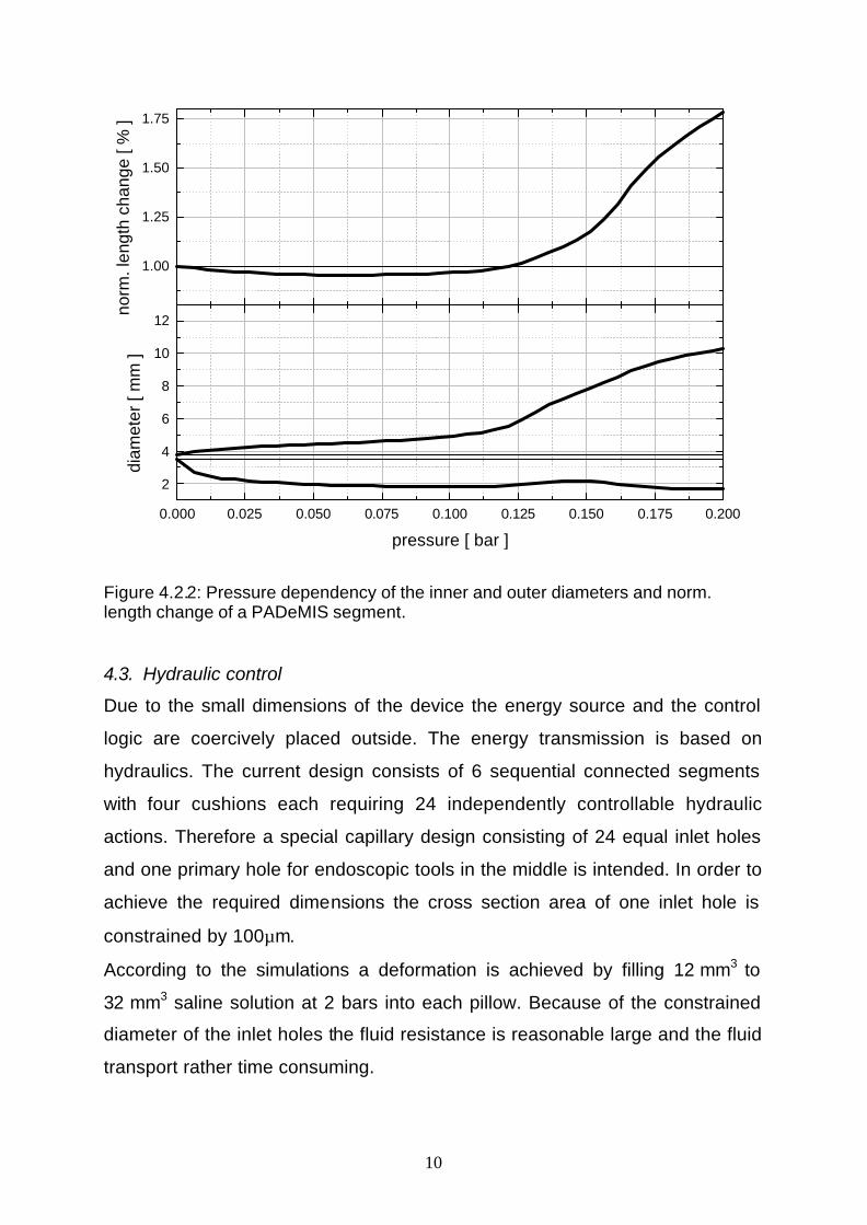
Figure 4.2.2 shows the length normalised against the initial cushion length and
the inner and outer diameter with respect to the pressure applied. The
decrease in length at small pressures is due to the deformation of the cushion
and the length increases when the SR starts stretching. Hence, this segment
could be used in a tube wi th a minimum diameter of 5mm. The segment
deformation is still being optimised.
The largest stretches in the segment occur at equibiaxial stress conditions. So
far uniaxial tension tests are performed in order to calculate Mooney-Rivlin
parameters. The occurring errors are difficult to estimate. Therefore,
equibiaxial stress tests are necessary.
10
0.000 0.025 0.050 0.075 0.100 0.125 0.150 0.175 0.200
2
4
6
8
10
12
diam
eter
[ m
m ]
pressure [ bar ]
1.00
1.25
1.50
1.75
norm
. len
gth
chan
ge [
% ]
Figure 4.2.2: Pressure dependency of the inner and outer diameters and norm. length change of a PADeMIS segment.
4.3. Hydraulic control
Due to the small dimensions of the device the energy source and the control
logic are coercively placed outside. The energy transmission is based on
hydraulics. The current design consists of 6 sequential connected segments
with four cushions each requiring 24 independently controllable hydraulic
actions. Therefore a special capillary design consisting of 24 equal inlet holes
and one primary hole for endoscopic tools in the middle is intended. In order to
achieve the required dimensions the cross section area of one inlet hole is
constrained by 100µm.
According to the simulations a deformation is achieved by filling 12 mm3 to
32 mm3 saline solution at 2 bars into each pillow. Because of the constrained
diameter of the inlet holes the fluid resistance is reasonable large and the fluid
transport rather time consuming.
11
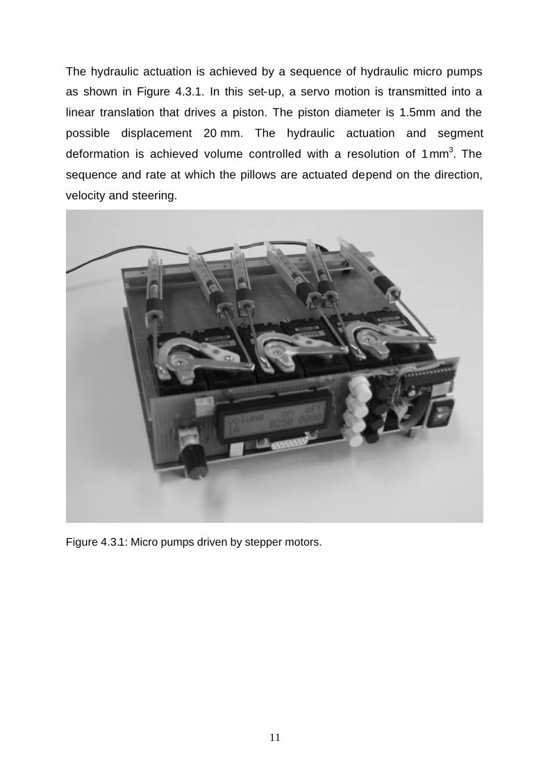
The hydraulic actuation is achieved by a sequence of hydraulic micro pumps
as shown in Figure 4.3.1. In this set-up, a servo motion is transmitted into a
linear translation that drives a piston. The piston diameter is 1.5mm and the
possible displacement 20 mm. The hydraulic actuation and segment
deformation is achieved volume controlled with a resolution of 1 mm3. The
sequence and rate at which the pillows are actuated depend on the direction,
velocity and steering.
Figure 4.3.1: Micro pumps driven by stepper motors.
12
5. Manufacturing technology
Several conventional manufacturing technologies producing work pieces from
silicone rubber have been established, e.g. injection moulding of medical
implants and extrusion of infusion or transfusion tubes. In fact, most of the
commercially available medical devices are produced by those techniques.
Thus, more complex structures are composed of several moulded primitives.
Due to the severe requirements concerning precision and complexity of the
stipulated design (i.e. a cylindrical body measuring an outer diameter of 4mm,
a remaining inside space of 2.5mm and an arrangement of cushions and inlet
capillaries embedded into the cylindrical shell) the standard manufacturing
techniques utilizing mould cores or extrusion cannot be applied to fabricate
PADeMIS.
Furthermore, silicone rubber being a soft, compliant and hyper elastic material
handling, positioning, gluing and post assembling are infeasible. In fact, mould
cores would most certainly break during positioning, fixation or injection of LR
silicone on account of their instability due to their miniature dimensions and
could not be removed mechanically.
Therefore, a chemically solvable mould core material in combination with dip
coating is examined. One or more sacrificial mould cores are dip-coated into a
silicone solution and the silicone layers are annealed. Thereafter, the mould
core is completely removed by solving it in an organic solvent. Through this
technique it is intended to reduce the mechanical strain to the mould core and
the silicone workpiece. [8-9].
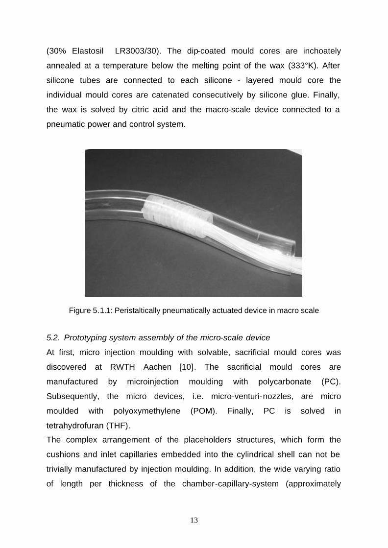
5.1. Manufacturing and testing in macro-scale
For studying the feasibility of the manufacturing process a macro size model
that is shown in Figure 5.1.1 has been produced by dip-coating and its
functionality successfully examined.
The mould cores were manufactured by injection moulding. A wax-like
substance that is solvable in citric acid was chosen as mould core material.
The single mould cores were dip-coated into a silicone – toluene solution
13
(30% Elastosil LR3003/30). The dip-coated mould cores are inchoately
annealed at a temperature below the melting point of the wax (333°K). After
silicone tubes are connected to each silicone - layered mould core the
individual mould cores are catenated consecutively by silicone glue. Finally,
the wax is solved by citric acid and the macro-scale device connected to a
pneumatic power and control system.
Figure 5.1.1: Peristaltically pneumatically actuated device in macro scale
5.2. Prototyping system assembly of the micro-scale device
At first, micro injection moulding with solvable, sacrificial mould cores was
discovered at RWTH Aachen [10]. The sacrificial mould cores are
manufactured by microinjection moulding with polycarbonate (PC).
Subsequently, the micro devices, i.e. micro-venturi-nozzles, are micro
moulded with polyoxymethylene (POM). Finally, PC is solved in
tetrahydrofuran (THF).
The complex arrangement of the placeholders structures, which form the
cushions and inlet capillaries embedded into the cylindrical shell can not be
trivially manufactured by injection moulding. In addition, the wide varying ratio
of length per thickness of the chamber-capillary-system (approximately
14
50..1000) results in an instability of the mould cores and complicates their
handling.
Therefore, dip coating combined with a lithography process has been
evaluated for processing silicone. Thus, PADeMIS is structured layer by layer.
Hence, direct mechanical handling of the sensitive mould cores is avoided.
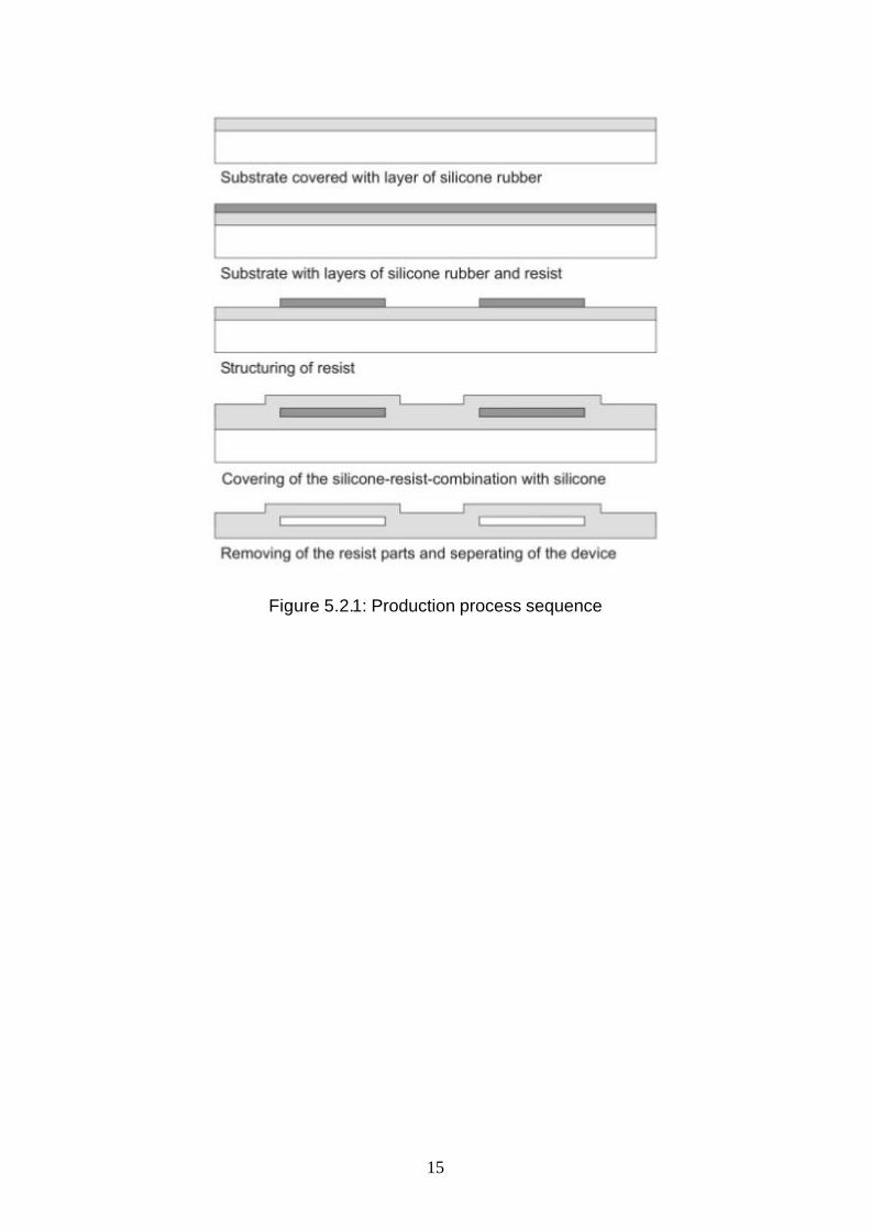
The process sequence is displayed in Figure 5.2.1.
The cylindrical format of the device is achieved by using a cylindrical rod as
substrate that is coated by a seceding film to enable the separation of the
finished device from the cylindrical rod. The substrate is dip-coated by LR
silicone and annealed. The sacrificial placeholder structures are attained by a
layer of resist that is homogenously sprayed onto the silicone surface by an
airbrush system. The resist layer is structured by laser-lithography. Thus,
cushions and capillaries are formed by the remained parts of the resist. If
another layer of silicone is brought onto the silicone–resist–pattern the resist
regions are embedded within a silicone shell. After the silicon is annealed the
resist parts are removed with acetone or another remover solution.
15
Figure 5.2.1: Production process sequence
16
6. Haptics
In minimal invasive surgery surgeons may compensate their lack of visibility
with the use of optical endoscopes, real time MRI or other image guided
systems. Although endoscopic tools with force feedback do exist the sense of
feel and touch as established in conventional surgery are not habitually
available during endoscopic surgery [11]. For PADeMIS it is considered to
integrate a component that is able to inspect the surrounding tissue in terms of
its structure and material composition. It is intended to analyse data that
reflects tactile sensation. Thus, a haptic sensor array is being developed and
measurement and evaluation principles are examined.
Principally, biological haptics refers to the modality of touch via skin
exteroceptors in combination with force proprioceptors. An observer senses
the shape, texture and to a certain extend the composition underneath the
surface of an object.
Three major research trends may be associated with haptics:
- Measuring tactile perception in terms of elasticity, viscosity, surface friction,
temperature, etc.
- Applying findings from physiological studies of human tactile perception to
the design of devices that replicate and stimulate the tactile sense and are
used as output devices, e.g. finger pad, glove.
- Determining the behaviour and response of objects subject to
displacement, manipulation and deformation. These are integrated into
virtual environments and simulators equipped with tactile or force feedback
devices, e.g. KISMET [12].
Here, the potentials of a novel method of diagnostics are studied by means of
in-vivo measurements of geometrical and mechanical properties. This haptic
information may be transferred from the place of surgery to an output device
accessible to the surgeon. The output can be in a graphical appearance or an
instrument stimulating the tactile senses in the surgeon’s finger tip. The
17
identification of the type and state of tissue is based of the varying different
mechanical characteristics, i.e. elasticity and viscosity.
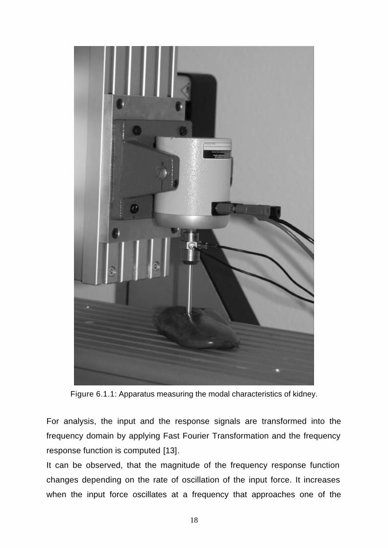
6.1. Measuring Principle
The measuring principle currently observed is based on modal analysis. Modal
analysis is a process, where the structure examined is described in terms of its
natural dynamical characteristics (modal parameters), which are its natural
frequencies, stiffness, damping and mode shapes. A test pin equipped with an
impedance head (accelerometer plus force sensor) is excited by a sinusoidal
signal with continuously varying frequencies (sweep) through the range of 5Hz
to 150Hz. The test pin is pressed to the tissue surface structure and the input
force and its response (acceleration) is recorded. The set-up can be seen in
Figure 6.1.1.
18
Figure 6.1.1: Apparatus measuring the modal characteristics of kidney.
For analysis, the input and the response signals are transformed into the
frequency domain by applying Fast Fourier Transformation and the frequency
response function is computed [13].
It can be observed, that the magnitude of the frequency response function
changes depending on the rate of oscillation of the input force. It increases
when the input force oscillates at a frequency that approaches one of the
19
natural frequencies of the excited tissue and is reaching its maximum at
resonance frequency.
6.2. Identification methods
The excited tissue region may be regarded as a one degree of freedom mass-
spring-damper system. Thus, the differential equation of motion is of the form:
)()()( tfkxtxctxm =++ &&& (6.2 .1)
Here, x , x& and x&& are the displacement, velocity and acceleration of the mass
m, k the stiffness and c the damping constant of the system (i.e. apparatus
and specimen) and f(t) the excitation force. A solution of the form tjXetx ω=)(
is assumed. ω is called the circular frequency fπω 2= . The equation can be
rewritten in the form:
tjtj eFXekcim ωωωω 02 )( =++− (6.2 .2)
In view of the fact that tjtj AeXex ωωω =−= 2&& the accelerance function of the
system may be determined by
kcjmjFjA
jH++−
−==
ωωω
ωω
ω 2
2
)()(
)(eAcceleranc (6.2 .3)
The accelerance is one option of describe the transfer function of the system
and it is defined as the ratio of acceleration (output) to force (input) in the
frequency domain [14]. By multiplying the equation by its complex conjugate
and given that 2n
km
ω= , where nω is the natural frequency of the undamped
system the modulus of the accelerance function is computed as
2
22
222 11
1)(
ωωω
ωc
k
jH
n
+
−
=eAcceleranc (6.2 .4)
When the independent variable ω approaches infinity the equation can be
reduced to
exap
n
mmkjH
+==
∞→
1)( 2
lim
ωωω
eAcceleranc
20
(6.2 .5)
apm and exm indicate the mass of the apparatus and the tissue being excited
respectively.
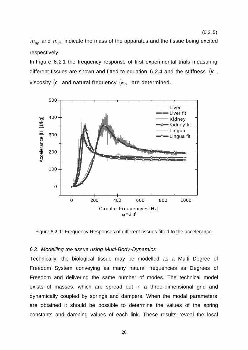
In Figure 6.2.1 the frequency response of first experimental trials measuring
different tissues are shown and fitted to equation 6.2.4 and the stiffness ( )k ,
viscosity ( )c and natural frequency ( )nω are determined.
0 200 400 600 800 1000
0
100
200
300
400
500
Liver Liver fit Kidney Kidney fit Lingua Lingua fit
Acc
eler
ance
|H| [
1/kg
]
Circular Frequency ω [Hz]ω=2πf
Figure 6.2.1: Frequency Responses of different tissues fitted to the accelerance.
6.3. Modelling the tissue using Multi-Body-Dynamics
Technically, the biological tissue may be modelled as a Multi Degree of
Freedom System conveying as many natural frequencies as Degrees of
Freedom and delivering the same number of modes. The technical model
exists of masses, which are spread out in a three-dimensional grid and
dynamically coupled by springs and dampers. When the modal parameters
are obtained it should be possible to determine the values of the spring
constants and damping values of each link. These results reveal the local
21
mechanical properties such as elasticity and viscosity that altering throughout
one tissue and amongst different types of tissue. Also, it may be possible to
recognise the boundary between two neighbouring tissues.
Acknowledgements
The authors thank Dr. H. Böhm, MD (Zentralklink Bad Berka GmbH), for his
inspirational input towards the project, Dr. Th. Müller (TEZ Jena) for his
cooperation during the animal studies. This study is funded by Thüringer
Ministerium für Wissenschaft, Forschung und Kunst.
References
[1] Michal W., Was den Menschen aufrecht hält, GEO 2/2004, pp. 98-114
(2004).
[2] Fletscher T.F., in Miller’s Anatomy of the dog, eds. H.E. Evans, W.B.
Saunders Company Philadelphia, pp. 800-828 (1993).
[3] MacKinnon P., Morris J. Lehrbuch der Klinischen Anatomie, Bern, Hans
Huber (1997).
[4] Panjabi M.M., Goel V. et al. Spine 17, pp. 299-306(1992).
[5] Mullins L., Effect of stretching on the properties of rubber, J. Rubber
Research 16, pp. 275-289 (1947).
[6] Mullins L., Softening of rubber by deformation, Rubber Chem. Technol.
42, pp. 339-362 (1969)
[7] Kohnke P., Ansys, Inc. theory: release 5.7, Chapter 4.5, Equation 4.177,
Ansys, (2001).
[8] Rogalla A.R., Analyse des Spritzgießens mikrostrukturierter Bauteile
aus Thermoplasten, Aachen, Institut für Kunststoffverarbeitung an der
RWTH Aachen (1998).
22
[9] Tomanek A., Silicone & Technik Ein Kompendium für Praxis, Lehre und
Selbststudium, München, Wacker-Chemie GmbH (1990).
[10] Ziegmann C, Wollbold J., Injection molding process and equipment for
molding microscopic plastic components with hollow chambers,
undercuts or channel uses soluble plastic insert Patent Publication
number: DE 19628766, Applicant: Vereinigung zur Förderung des
Institutes für Kunststoffverarbeitung in Industrie und Handwerk an der
Rhein.-Westf. Technischen Hochschule Aachen (1998).
[11] Rosen J., Force controlled and teleoperated endoscopic grasper for
minimally invasive surgery – experimental performance evaluation,
IEEE Transactions on Biomedical Engineering, 46, pp. 1212–1221
(1999)
[12] Kühnapfel U., Endoscopic Surgery Training using Virtual Reality and
deformable Tissue Simulation, Computers & Graphics, 24, pp. 671-682,
(2000)
[13] Sudhakar M.P. Modal and Spectrum Analysis: Data Dependent
Systems in State Space, New York, John Willey & Sons, Inc. (1991).
[14] Ewins D.J. Modal Testing theory practice and application, ed. 2,
Baldock, England, Research Study Press Ltd. (2000).