Embed Size (px)
Citation preview
DEVELOPMENT OF CHITOSAN BASED NANOCOMPOSITE
FILM FOR THE WING MEMBRANE OF BIOMIMETIC MICRO
AIR VEHICLES (BMAV)
RUBENTHEREN VIYAPURI
THESIS SUBMITTED IN FULFILMENT OF THE
REQUIREMENTS FOR THE DEGREE OF DOCTOR
OF PHILOSOPHY
FACULTY OF ENGINEERING
UNIVERSITY OF MALAYA
KUALA LUMPUR
2016

ii
UNIVERSITY OF MALAYA
ORIGINAL LITERARY WORK DECLARATION
Name of Candidate: (I.C/Passport No: )
Registration/Matric No:
Name of Degree:
Title of Project Paper/Research Report/Dissertation/Thesis (“this Work”):
Field of Study:
I do solemnly and sincerely declare that:
(1) I am the sole author/writer of this Work;
(2) This Work is original;
(3) Any use of any work in which copyright exists was done by way of fair dealing
and for permitted purposes and any excerpt or extract from, or reference to or
reproduction of any copyright work has been disclosed expressly and
sufficiently and the title of the Work and its authorship have been
acknowledged in this Work;
(4) I do not have any actual knowledge nor do I ought reasonably to know that the
making of this work constitutes an infringement of any copyright work;
(5) I hereby assign all and every rights in the copyright to this Work to the
University of Malaya (“UM”), who henceforth shall be owner of the copyright
in this Work and that any reproduction or use in any form or by any means
whatsoever is prohibited without the written consent of UM having been first
had and obtained;
(6) I am fully aware that if in the course of making this Work I have infringed any
copyright whether intentionally or otherwise, I may be subject to legal action
or any other action as may be determined by UM.
Candidate’s Signature Date:
Subscribed and solemnly declared before,
Witness’s Signature Date:
Name:
Designation:

iii
ABSTRACT
Biomimetic Micro Air Vehicles (BMAV) are unmanned, micro-scaled aircraft that are
bioinspired from flying organisms to achieve lift and thrust by flapping their wings. There
are still many technological challenges involved with the designing BMAV. One of these
is designing ultra-lightweight materials and structures for the wings that have the
mechanical strength to withstand continuous flapping at high frequencies (e.g. 30 Hz for
a dragonfly). Insects achieve this by using chitin-based, wing frame structures that
encompass a thin, film membrane. The overall objective of this research is to develop an
innovative wing membrane for a BMAV, bioinspired from actual dragonfly wings.
Chitosan was used as a polymer matrix. Chitin nanowhiskers (CNW) and nanocrystalline
cellulose (NCC) were prepared in laboratory and used as reinforcement fillers in the
design of two types of nanocomposite membranes. In each type, tannic acid was used as
crosslinker for the chitosan matrix. Film samples with different ratios of nanomaterials
and crosslinking agent were prepared. The chemical changes, structural properties, and
mechanical performance of each sample was measured, analyzed, and compared.
Following these initial studies, heat treatment was also investigated to assess its potential
for improving the chitosan nanocomposite film. Transmission electron microscopy
(TEM) and scanning electron microscope (SEM) confirms the nano-scaled size of
nanomaterial produced and reveals the dispersion level of the nanomaterials in the
chitosan matrix. Fourier-transform-infrared spectroscopy (FTIR) was used to investigate
the molecular interaction of film. X-ray diffraction (XRD) results indicated that the
nanocomposite films have a rigid structure. Performance analysis using a universal testing
machine (UTM) and nanoindentation machine indicates that, the tensile strength and
modulus increase significantly for the crosslinker nanocomposite films. Wettability,
moisture content and solubility tests show that the film exhibits elevated water resistant
when the additives and heat treatment are introduced. A dragonfly wing frame structure

iv
was also bio-mimicked and fabricated using a 3D printer. The membrane was applied to
these BMAV wing frames by a casting method. A flapping generator was used to produce
static, flapping motion on these BMAV wings and an actual dragonfly wing (for
comparison). The aeroelastic properties of both the BMAV and actual dragonfly wings
were examined using two high speed frame camera. Bending angle, wing tip deflection
and wing tip twist angle were analyzed at the flapping frequencies of 30 Hz, 60 Hz and
120 Hz.

v
ABSTRAK
Kenderaan udara Biomimetic mikro (BMAV) adalah pesawat tanpa pemandu, bersaiz
mikro. Ia diilhamkan daripada penerbangan serangga yang boleh terbang dan burung
untuk mencapai daya angkat dan daya tujahan dengan meniru cara cara atau prinsip
penerbangan dengan mengimbas sayap secara semula jadi. Masih terdapat banyak
cabaran teknologi yang terlibat dalam merekabentuk BMAV. Salah satu daripadanya
adalah merekabentuk bahan-bahan yang sangat ringan dan struktur sayap yang
mempunyai kekuatan mekanikal untuk menahan data tujahan dan daya angak secara
berterusan pada frekuensi tinggi (contohnya 30 Hz untuk Pepatung). Secara amnya,
Pepatung mencapai matlamat ini dengan menggunakan bahan semula jadi sayap iatu
Chitin. Sayap Pepatung mempunyai struktur rangka yang yang nipis dan mempunyai
lapisan filem membrane yang amat nipis. Objektif keseluruhan kajian ini adalah untuk
merekabentuk membran sayap inovatif bagi BMAV, berdasarkan daripada bahan sayap
Pepatung sebenar. Chitosan digunakan sebagai matriks polimer. Nanowhiskers chitin
(CNW) dan Selulosa nanokristal (NCC) telah disediakan di makmal dan digunakan
sebagai pengisi tetulang dalam rekabentuk dua jenis membran nanokomposit. Dalam
setiap jenis film, asid tannic digunakan sebagai crosslinker untuk matriks chitosan. Filem
dengan nisbah yang berbeza dan unik telah disediakan menggunakan bahan nano dan ejen
crosslinking telah disediakan. Perubahan kimia, sifat struktur dan pretasi mekanikal pada
setiap sampel telah diuji, dianalisis dan dibandingkan antara satu sama yang lain.
Berikutan kajian-kajian awal, rawatan haba juga disiasat untuk menilai potensinya untuk
meningkatkan ciri-ciri mekanikal filem nanokomposit chitosan. Mikroskop Transmisi
Elektron (TEM) dan Mikroskop Elektron (SEM) mengesahkan saiz nano bahan yang
telah disediakan dihasilkan dan mendedahkan tahap penyebarannya dalam matriks
chitosan. Spektroskopi inframerah Fourier (FTIR) telah digunakan untuk menyiasat
interaksi molekul filem. Keputusan belauan sinar-x (XRD) menunjukkan bahawa filem-
vi
filem nanokomposit mempunyai struktur yang tegar. Analisis prestasi menggunakan
Mesin nanoindentation dan mesin ujian tensile (UTM) menunjukkan bahawa, kekuatan
tegangan dan modulus meningkat secara signifikan untuk filem-filem nanocomposite
crosslinker. Ujian wettability, kandungan kelembapan dan keterlarutan menunjukkan
bahawa filem ini mempamerkan sifat-sifat tahan air apabila aditifkan dan rawatan haba
diperkenalkan. Struktur rangka sayap dragonfly turut bio-mimicked dan fabrikasi
menggunakan pencetak 3D. Membran ini dilekatkan pada bingkai sayap BMAV ini
melalui kaedah casting. Sebuah penjana penerbangan sayap telah digunakan untuk
menghasilkan pergerakan berasakan aliran bersayap. Kajian dilakukan terhadap BMAV
dan sayap pepatung sebenar (untuk perbandingan). Sifat-sifat aeroelastic BMAV dan
sayap pepatung sebenar diperiksa menggunakan dua kamera video berkelajuan tinggi.
Sudut lenturan, pesongan hujung sayap dan putaran sudut sayap dianalisis pada frekuensi-
frekuensi flapping 30 Hz, 60 Hz dan 120 Hz.

vii
DEDICATIONS
With the blessings of Almighty, this thesis is dedicated especially
to my beloved father and mother,
Mr. Viyapuri Muniandy and Ms. Vijiya Periasamy
The caring ones,
Jagadish Viyapuri, Devendran Ramachandran
Yogalakshimee Viyapuri,Vithiya Viyapuri
Anithambigai Permal, I.R. Prakash, Naresh Kumar
Friends,
Shanmarkkan, , Prashana,Magilan, Suresh, Manimaran, Kamallan, Derrick
Relatives
Kumar, Mugilan Manickam,Ganesen, Malathy,Siva Jothy, T.Kumar, Justin
Respected supervisor,
Dr. Thomas Arthur Ward
Dr.Ching Yern Chee
Thanks for all the supports.
My love for you all remains forever.
viii
ACKNOWLEDGEMENT
I take this opportunity to express my profound gratitude to my supervisor Dr.
Thomas Arthur Ward for his exemplary guidance, monitoring, patience and constant
encouragement throughout the duration of my studies. I would also like to acknowledge
with much appreciation the crucial role of my co-supervisor Dr. Ching Yern Chee for
guiding me professionally throughout the candidature.
I would like to express the deepest appreciation to all my lab members Mr.
Cristhoper Fearday, Ms. Praveena Nair and Mr. Erfan Salami. They have been a good
companion on an exhausting and disappointing experiment. In many ways I have learnt
so much from them. I’m thankful for being blessed with a friendly and cheerful group. I
also take this opportunity to express a deep sense of gratitude to lab assistants Mr. Adli
and Ms. Liyana who have helped me directly and indirectly into technical knowhow.
Special thanks to University Malaya for sourcing me a quality workstation.
Of course no acknowledgments would be complete without giving thanks to my
family. I would like to thank my parents for their unconditional support, both financially
and emotionally throughout my candidature. In particular, the absolute love and blessing
showered by my mum, dad, brothers and sisters. A special thanks to Anithambigai for her
dedication into helping me completing this thesis.
Above all, I thank God for his grace, wisdom, favors and protections. I could never
have done this without the faith I have in you, the Almighty.
There are so many others whom I may have inadvertently left out and I sincerely
thank all of them for their help.
ix
TABLE OF CONTENTS
PAGE
ABSTRACT iii
DEDICATION vii
ACKNOWLEDGEMENT viii
TABLE OF CONTENT ix
LIST OF FIGURES xiv
LIST OF TABLES xvii
LIST OF SYMBOLS AND ABBREVIATIONS xviii
LIST OF APPENDICES xxii
CHAPTER 1: INTRODUCTION 1
1.1 Overview 1
1.2 Problem statement 2
1.3 Preliminary studies 4
1.3.1 Honey bee 4
1.3.2 Cicada 5
1.3.3 Dragonfly 5
1.4 Objectives 6
1.5 Procedures 7
1.6 Outline of thesis 8
x
CHAPTER 2: LITERATURE REVIEW 10
2.1 Introduction 10
2.2 Biomimetic Micro Air Vehicle (BMAV) 10
2.2.1 Challenges associated with BMAV 11
2.2.2 BMAV wing structure and materials 12
2.3 Polysaccharides as a biocomposite film 14
2.3.1 Chitin 15
2.3.2 Chitin nanowhiskers (CNW) 16
2.3.3 Chitosan 18
2.3.4 Modification of chitosan 19
2.3.5 Cellulose 20
2.3.6 Nanocrystalline cellulose (NCC) 22
2.4 Polymer crosslink 23
2.4.1 Tannic acid 25
2.5 Polylactic acid (PLA) 26
CHAPTER 3: RESEARCH METHODOLOGY 28
3.1 Introduction 28
3.2 Preparation of nanomaterial 28
3.2.1 Preparation of CNW 28
3.2.2 Preparation of nanocrystalline cellulose (NCC) 30
3.3 Preparation of nanocomposite film 32

xi
3.3.1 Preparation of chitosan nanocomposite film 32
3.3.2 Preparation of heat treated chitosan nanocomposite film 33
3.4 Film nomenclature 33
3.5 BMAV wing membrane and wing structure 34
3.6 Characterization and performance test 37
3.6.1 Morphological studies by Transmission Electron Microscope 38
3.6.2 Morphological studies by Scanning Electron Microscope 39
3.6.3 Chemical interaction studies by Fourier-transform-infrared
spectroscopy (FTIR) 40
3.6.4 Chemical interaction studies by X-ray diffraction (XRD) 40
3.6.5 Performance testing using Universal Testing Machine (UTM) 41
3.6.6 Performance testing by physicochemical test 42
3.6.7 Performance testing by water contact angle test 43
3.6.8 Performance testing by optical transmittance 43
3.6.9 Performance testing by electromagnetic actuated flapping wing
mechanism 43
3.6.10 Performance testing by nanoindentation test 45
CHAPTER 4: RESULTS AND DISCUSSION 47
4.1 Introduction 47
4.2 Morphological studies (TEM) 47
4.2.1 Chitin nanowhiskers (CNW) 47

xii
4.2.2 Nanocrystalline cellulose (NCC) 49
4.3 Morphological studies (SEM) 52
4.4 Chemical interaction studies by FTIR analysis 54
4.4.1 Chitosan film with CNW and tannic acid 54
4.4.2 Heat treated chitosan film with CNW and tannic acid 57
4.4.3 Chitosan film with NCC and tannic acid 60
4.4.4 Heat treated chitosan film with NCC and tannic acid 62
4.5 Chemical interaction studies by XRD analysis 64
4.5.1 Chitosan film with CNW and tannic acid 64
4.5.2 Heat treated chitosan film with CNW and tannic acid 66
4.5.3 Chitosan film with NCC and tannic acid 69
4.5.4 Heat treated chitosan film with NCC and tannic acid 70
4.6 Performance testing by UTM test 72
4.7 Performance testing by physicochemical studies 84
4.8 Performance testing by water contact angle (Wettability) 87
4.9 Performance testing by optical transmittance
(UV-visible spectrophotometer) 91
4.10 Performance testing by nanoindentation test 93
4.11 Performance testing by flapping mechanism 97
4.11.1 Bending angle 98
4.11.2 Wing tip deflection 100
xiii
4.11.3 Wing tip twist angle 101
CHAPTER 5 – CONCLUSION 103
5.1 Summary 103
5.2 Other uses of film beside BMAV 105
5.3 Recommendation for future research 106
REFERENCES 108
LIST OF PUBLICATIONS CONFERENCE PRESENTATION
AND PATENTS 122
APPENDICES 124

xiv
LIST OF FIGURES
PAGE
Figure 1.1 Illustration of the overall idea to develop BMAV 8
wing membrane
Figure 2.1 Chemical structure of chitin 16
Figure 2.2 Procedure for the preparation of polymer/CNW 18
nanocomposites by casting-evaporating method
Figure 2.3 Chemical structure of chitosan 19
Figure 2.4 Arrangement of fibrils, microfibrils and cellulose 21
in cell walls
Figure 2.5 Chemical structure of cellulose 22
Figure 2.6 Illustration of crossliking process in a polymer; 24
(1) Crosslinking agent is introduced in polymer matrix,
(2) Growth and branching,
(3) Fully cured polymer
Figure 2.7 Chemical structure of tannic acid 26
Figure 3.1 Schematic diagram of CNW production by 29
hydrolysis process
Figure 3.2 Schematic representation of the preparation of NCC 30
starting from MCC showing the surface esterification
reaction introducing sulfate groups
Figure 3.3 Dark colored solution in the central conical flask 31
depicts the “burned” sample; The most right conical
flask contains a correct sample
Figure 3.4 3D model of simplified dragon wing structure; 36
(a) Top view fore wing, (b) Iso view forewing,
(c) Top view hind wing, (d) Iso view of hind wing,
(e) Fabricated dragonfly wing
Figure 3.5 Wing structure immersed in chitosan nanocomposite 37
Solution; (a) Fore wing, (b) Hind wing
Figure 3.6 SEM film samples coated with gold prior viewing 39
Figure 3.7 Flapping wing mechanism setup 44
Figure 3.8 Graph of indention load P; Penetration depth h; 46
showing the process of loading and unloading of
the nanoindenter.
xv
Figure 4.1 TEM images of nano-scale chitin whiskers in dilute 49
HCI, (a) Magnified at 500 nm with measured length,
(b) Magnified at 200 nm with measured width
Figure 4.2 TEM images of NCC in aqueous medium, 51
(a) magnified at 500 nm with measured length,
(b) magnified at 500 nm with measured width
Figure 4.3 SEM micrograph of surface (a-d): (a) Set I; 54
(b) Set II (B); (c) Set III (C); and (d) Set IV (F);
Cross-section (e-h): (e) Set I; (f) Set II (B);
(g) Set III (C); and (h) Set IV (F)
Figure 4.4 FTIR absorption spectra of pure chitosan film (Set I) 55
Figure 4.5 FTIR spectra of;(a) chitosan matrix with CNW, 57
(b) chitosan matrix with CNW and tannic acid
Figure 4.6 FTIR spectra of treated and untreated samples, 60
(a) Set I, (b) Set II (A), (c) Sample III (A),
(d) Set IV (A)
Figure 4.7 FTIR spectra of: (a) non-crosslinked chitosan film, 62
(b) crosslinked chitosan film (40mg), (c) Comparison
of similar dosage between CNW and NCC
Figure 4.8 Comparison between CNW and NCC heat treated 64
chitosan film: (a) Without crosslinker, (b) with
crosslinker
Figure 4.9 XRD diffractograms of selected CNW based chitosan 65
film
Figure 4.10 XRD diffractograms of CNW based chitosan film, 68
(a) Set I, (b) Set II (A), (c) Set III (A), (d) Set IV (A)
Figure 4.11 Comparison of X-ray diffractograms of chosen sample 70
sets
Figure 4.12 XRD diffractograms of : (a) Set III (A) and 71
Set IV (A)
Figure 4.13 Average mechanical properties of pure chitosan (Set I) 74
and crosslinked chitosan film (set II), (a) Tensile
strength, (b) Elongation at break, (c) Young’s Modulus
Figure 4.14 Mechanical properties of CNW based chitosan film 76
with and without crosslinker; (a) Tensile strength,
Elongation at break, (c) Young’s Modulus

xvi
Figure 4.15 Mechanical properties of NCC based chitosan film with 80
and without crosslinker; (a) Tensile strength,
(b) Elongation at break, (c) Young’s Modulus,
(d) Comparison of tensile strength between CNW and
NCC based chitosan film
Figure 4.16 Comparison of both heat treated and non-treated 83
nanocomposite film; (a) Tensile strength, (b) Elogation
at break, (c) Young’s Modulus
Figure 4.17 Physicochemical characterization of all sample sets; 85
(a) Moisture content of samples under equilibrium
condition at 25 °C and 65% Relative Humidity,
(b) Solubility of samples
Figure 4.18 Moisture content of both treated and untreated 87
samples ; (a) CNW based chitosan film, (b) NCC
based chitosan film
Figure 4.19 Water contact angle of; (a) Set I, (b) Set II (A), 90
(c) Set III (A-CNW), (d) Set IV (A-CNW),
(e) Set III (A-NCC), (f) Set IV (A-NCC), (g-l) Heat
treated counterpart
Figure 4.20 Water contact angle of actual dragonfly wing 91
Figure 4.21 Appearance of all sample sets; (a) Set I; 92
(b) Set II (A); (c) Set II (B); (d) Set III (A);
(e) Set III (B); (f) Set III (C); (g) Set IV (A); (h) Set IV
(B); (i) Set IV (C); (j) Set IV (D); (k) Set IV (E);
(l) Set IV (F)
Figure 4.22 UV-visible spectrophotometer of chosen sample sets 93
Figure 4.23 Points of nanoindentation test; (a) Actual 95
dragonfly forewing, (b) Actual dragonfly hindwing,
(c) BMAV forewing, (d) BMAV hindwing
Figure 4.24 Bending angle of actual dragonfly wings and BMAV 99
wing
Figure 4.25 Wing tip deflection of actual dragonfly wings and 100
BMAV wing
Figure 4.26 Wing tip twist angle of actual dragonfly wings and 102
BMAV wing
xvii
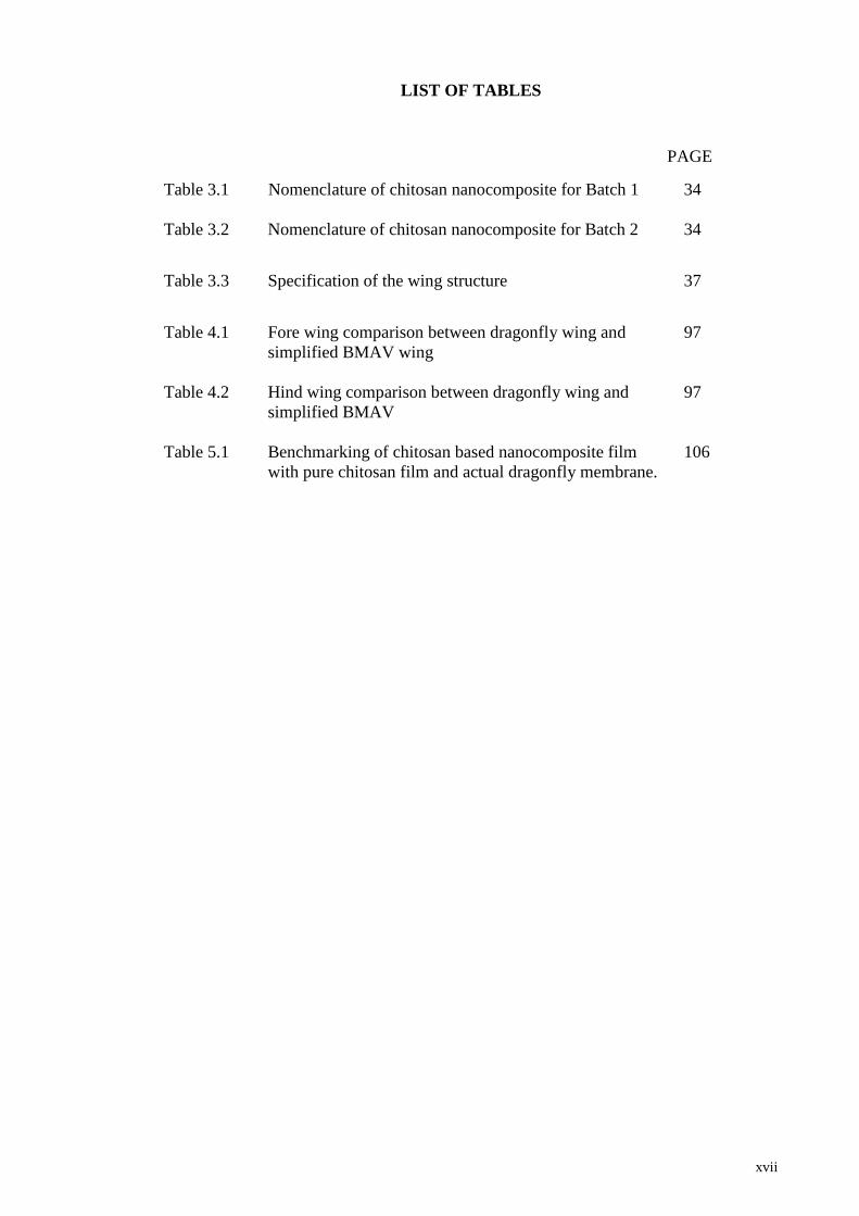
LIST OF TABLES
PAGE
Table 3.1 Nomenclature of chitosan nanocomposite for Batch 1 34
Table 3.2 Nomenclature of chitosan nanocomposite for Batch 2 34
Table 3.3 Specification of the wing structure 37
Table 4.1 Fore wing comparison between dragonfly wing and 97
simplified BMAV wing
Table 4.2 Hind wing comparison between dragonfly wing and 97
simplified BMAV
Table 5.1 Benchmarking of chitosan based nanocomposite film 106
with pure chitosan film and actual dragonfly membrane.

xviii
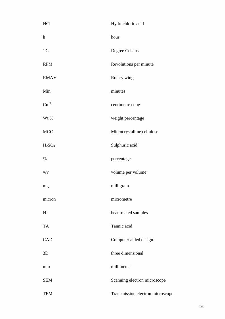
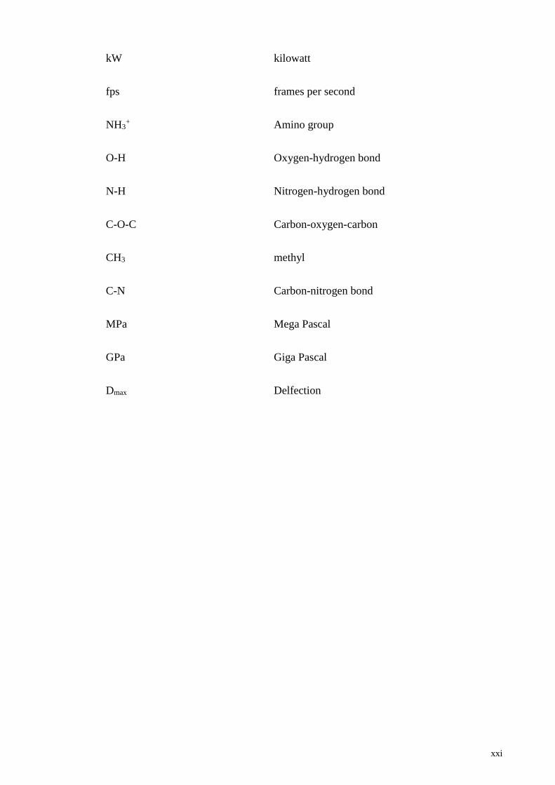
LIST OF SYMBOLS AND ABBREVIATIONS
Symbols and Abbreviations Full name
UAV Unmanned aerial vehicle
MAV Micro air vehicle
VTOL Vertical take-off and landing
BMAV Biomimetic micro air vehicle
DA Acetylation
FMAV Fixed wing
GlcN 2-amine 2-deoxy- ᴅ - glucopyranoside
GlcNAc 2-acetamide-2-deoxy-ᴅ-glucopyranose
Hz Hertz
Re Reynolds number
G Gravity
PLA Polylactic acid
CNW Chitin nanowhiskers
NCC Nanocrystalline cellulose
UM Universiti of Malaya
g Grams
ml Millilitre
N Normality
xix
HCl Hydrochloric acid
h hour
˚ C Degree Celsius
RPM Revolutions per minute
RMAV Rotary wing
Min minutes
Cm3 centimetre cube
Wt % weight percentage
MCC Microcrystalline cellulose
H2SO4 Sulphuric acid
% percentage
v/v volume per volume
mg milligram
micron micrometre
H heat treated samples
TA Tannic acid
CAD Computer aided design
3D three dimensional
mm millimeter
SEM Scanning electron microscope
TEM Transmission electron microscope

xx
FTIR Fourier Transform Infrared Spectroscopy
XRD X-Ray Powder Diffraction
UTM Universal Testing Machine
UV Ultra violet
µm micrometer
cm-1 per centimeter
Cu Kα Copper K-alpha
Å Angstrom
kV kilo volt
mA milliamp
θ theta
˚ Degree
N Newton
ASTM American Society for Testing and Materials
RH Relative humidity
Ws Weight of swollen sample
Wi Weight of sample after heating
s Seconds
µL microliter
nm nanometer
Tr Optical transmittance
xxi
kW kilowatt
fps frames per second
NH3+ Amino group
O-H Oxygen-hydrogen bond
N-H Nitrogen-hydrogen bond
C-O-C Carbon-oxygen-carbon
CH3 methyl
C-N Carbon-nitrogen bond
MPa Mega Pascal
GPa Giga Pascal
Dmax Delfection
xxii
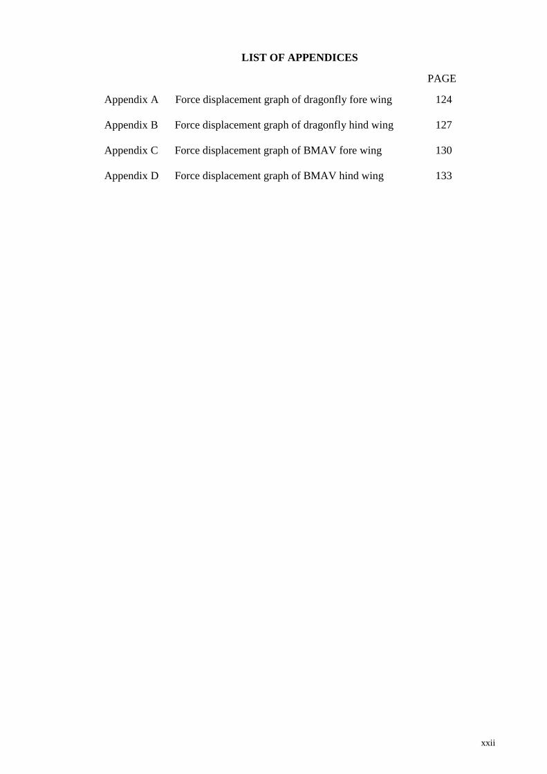
LIST OF APPENDICES
PAGE
Appendix A Force displacement graph of dragonfly fore wing 124
Appendix B Force displacement graph of dragonfly hind wing 127
Appendix C Force displacement graph of BMAV fore wing 130
Appendix D Force displacement graph of BMAV hind wing 133

1
CHAPTER 1: INTRODUCTION
1.1 Overview
Unmanned air vehicles (UAV) are unmanned, aircraft that is flown remotely by
pilot at a ground station. Although basic models were first deployed in 1916 (during
World War I), they only came into prominence for military use in the last 20 years
(Yahyanejad & Rinner, 2015). They have also become increasingly popular for civil
applications (e.g. agricultural modeling, land use planning, industrial site surveys, film
production, etc.). Recent advances in rapid development and miniaturization technologies
has allowed a new class of micro-scaled UAVs to be developed, called Micro Air
Vehicles (MAV). In a Broad Agency Announcement (BAA 97-29), the US Defense
Advanced Research Projects Agency (DARPA) defined MAV as being less than 15 cm
in any dimension. Later in 2005 (BAA 06-06), DARPA defined nano air vehicles (NAV)
as being no larger than 7.5 cm or heavier than 10 g (carrying a 2 g payload) (Ward et al.,
2015). Numerous MAV concepts have been proposed since then. These can be
categorized into three types of MAV: fixed wing, (FMAV), rotary wing (RMAV), and
biomimetic or flapping wing (BMAV).
The focus of this research is BMAV (also called an ornithopter). This concept has
been discussed for centuries, most famously in 1485 by Leonardo da Vinci in his
theoretical ornithopter designs (Reay, 1977). Despite this long history, a working
operational ornithopter (or BMAV) could not be achieved before now, because the level
of technology was insufficient. A BMAV is a micro-scaled (or nano-scaled) aircraft that
biomimics the flapping wing motion of small biological flying organisms (e.g. insects,
bats, or birds) to generate lift and thrust (Dietl & Garcia, 2013). Like their biological
2
counterparts, BMAV are highly maneuverable and ultra-lightweight. Their small size and
weight along with their potential flight agility, make them capable of flying in confined
areas and even indoors. The vortices produced by flapping wing allow them to generate
aerodynamic forces at higher magnitudes than fixed wings. This means that flapping
wings are able to produce as much lift as a larger (surface area), fixed wing (Maxworthy,
1981). So BMAV are potentially the smallest of all the MAV types. However, the
technological complexities involved with BMAV designs are much greater than FMAV
or RMAV. This means that unlike the other two types, there are currently no BMAV in
operational service yet.
BMAV are envisioned to carry ultra-lightweight, compact electronics and
surveillance detection equipment as a primary payload. They can be deployed by a single
operator, and relatively inexpensive to fabricate. BMAVs are envisioned for use on civil
and military missions that are of a limited duration, such as (Wu et al., 2014; Nguyen,
Ha, & Lee, 2015)
Remote sensing of hazard sites (i.e. chemical spill, radiation, high voltage
area)
Indoor/Outdoor videography
Police and military surveillance
1.2 Problem statement
As BMAV is a new generation of miniaturized aircraft, there is an unlimited
potential of research can be carried to harness its potential. BMAV bio inspired from
flying insects are of great interest since insects have a maneuvering agility and can fly in
compact areas. Flying insects have a simpler control processes then birds and bats have a
3
musculature system along the span of their wings. With these advantages, flying insects
have been the focus of much attention in the research field.
Some of the challenges associated with bio mimicking flying insects is, generating
high flapping frequencies raising from 30 Hz for a dragonfly to 300 Hz for a housefly
(depending on the species) in the sensitive Reynolds number (Re) region of less than
10000 (Levy & Seifert, 2010; Rajabi, Moghadami, & Darvizeh, 2011). The wing structure
and membrane of the BMAV must be flexible but strong enough to endure the
aerodynamic forces produced by flapping motion. During flight, the flying insect wings
undergo significant bending and twisting deformations that can alter the direction and
magnitude of the aerodynamic forces being generated. Therefore, the artificial wing is a
critical component of BMAV.
Research conducted by Combes, (2010) who studied the material and structure of
varieties of insects as an inspiration for BMAVs concluded that, although the primary
function of most insects wings is to generate aerodynamic forces, their wing design may
reflect trade-offs or specialization for other aspects of flight performance, such as
efficiency, versatility, maneuverability, or stability. In general, the mechanical properties
decline with decreasing volume. Since insect wings are very small compared to birds,
mimicking them is a challenging and exciting task. Overall objective of this research is
to analyze and study the natural materials that a variety of which flying insects are
composed.
Studying this topic in Malaysia is advantages since the biodiversity of Malaysian
tropical forest assures abundant insects to investigate. My initial focus was to understand
active flying insect’s wing materials and structures. Ideal candidates to bio mimic are
dragonfly (Anisoptera), Honey bees (Apis) and Cicada (Cicadidae). These active flyers
can be found in urban areas as well as the jungle. These insects in particular have shown
peculiar ability to navigate in these difficult locations on a regular basis due to their high

4
agility. They have the flying characteristics that is useful if mimicked for BMAV to
navigate through urban environments, building interiors and difficult or dangerous
locations.
Besides having a durable wing membrane material, it is envisioned that future
BMAV will be deployed using swarm technology in one-way (disposable) missions
(Kushleyev et al., 2013). Swarm technology utilizes networking capability to
communicate into each other. Payloads such tiny camera and sensor deemed to be very
effective by sweeping over a wide area of coverage using this technology. Therefore, this
requires the artificial wing structure and membrane to be composed of biodegradable and
biocompatible materials so not to pose risk to the biosphere.
1.3 Preliminary studies
Inspired by biomaterial and their unique properties, this study was conducted to
produce a high strength bio based film. This film would be used for the application of
BMAV wing membrane. From preliminary research, all the potential flying insects wing
(Dragonfly, Honey bee and Cicada) are made of chitin material embedded with proteins
(Kaya et al.,2015; Sajomsang & Gonil, 2010; Hou et al., 2015). Their wing design and
profile is unique to each other and contributes to their flying skills.
1.3.1 Honey bee
Honey bees spend most of their time flying to retrieve nectar and pollen from
flowers. The flapping frequency of honey bees is in the range of 180 Hz to 250 Hz
(Rittschof & Seeley, 2008). They take off with an explosive buzz sound initially to
overcome body weight by sudden boost of flapping frequency. The wings are small in

5
proportion to their size, which is why they need to flap at such a high frequency. Since
the flapping frequency of honey bees is very high, it is difficult to artificially replicate
their flapping frequency. Furthermore, the wing size is relatively smaller then cicada or
dragonflies, so honey bees were not considered as a candidate for bio mimicking in this
research.
1.3.2 Cicada
Cicada have prominent eyes set wide apart with short antennae and membranous
front wings. They are relatively large insects and flaps its wing in a figure of 8 motion
(Jaderic & Huang, 2011). They possess a larger upward protruding wing design that is
larger than their body (Luo & Wei, 2015). Cicadas are not an active flyers, rather can
better described as long hoppers. Very few researchers have used Cicada as a reference
for a BMAV wing design since they have a large weight-to-wing ratio (Jaderic & Huang,
2011; Xinyan, Schenato, & Sastry, 2006). Since the complex flapping mechanism of
cicada is challenging, I have opted not to focus on them for bio mimicry.
1.3.3 Dragonfly
Dragonflies are highly agile flyers (Nagai et al., 2009; Thomas et al., 2004). These
flying insects are capable of migrating across oceans, moving in any direction, and
suddenly changing course. They can hover and accelerate quickly both from dead stop as
well from a hovering attitude. Their wings are long, narrow and significantly larger than
their body. Dragonfly wings possess a remarkably high power/weight ratio. A study
conducted by Chen et al., (2013), reported that a dragonfly can accelerate at 4G (G-Force)
linearly and 9G in sharp turns while pursuing prey. Sunada, Zeng and Kawachi 1998;
Dickinson, Lehmann and Gotz, (1993) revealed that the wing motion of dragonfly wing

6
is controlled by the wing root muscle only, which is easier to mimic in a BMAV then the
wing motions used by other insects. These qualities makes dragonfly a preferred
candidate to be bio mimicked in a BMAV.
1.4 Objectives
Overall objective of this research is to develop a bio-based thin film as a
membrane for BMAV using natural occurring polysaccharides. A literature review will
be carried out on a variety of insects in Malaysia for their flying ability and harnessing
their natural material to mimic its mechanical properties for the usage BMAV wing
membrane. My driving criteria is that the wing membrane must match or surpass the
mechanical properties of an actual dragonfly wing membrane. Chitosan (which is a
deacetylation of chitin) was selected as the matrix for the wing membrane. Methods for
enhancing chitosan were studied extensively to match the mechanical properties of actual
dragonfly membrane. Nanomaterial and crosslinking were incorporated into chitosan
matrix and their role in molecular interaction and alteration of properties was examined.
Once membrane is created, a Polylactic acid (PLA) based material will be used as a wing
frame structure and further tests will be conducted and compared with actual dragonfly
wing. Listed below are the primary objectives that must be fulfilled in order to design a
new BMAV wing membrane:
Process and fabricate chitosan nanocomposite membranes for the wing of
a dragonfly bio inspired BMAV
Examine the mechanical, physical and chemical properties of the
membrane
Apply membrane on a dragonfly like wing frame structure and investigate
its nanomechanical properties and aeroelasticity

7
1.5 Procedures
Figure 1.1 illustrates the overall idea of the development of wing membrane for
BMAV. Each process will be discussed in detail in the methodology section. The
summary of procedures conducted in this experiment is listed below:
1. Mimicking selected insect’s wing membrane material artificially with chitosan as
a film matrix.
2. Enhancement of chitosan bio film by means physical and chemical reinforcement.
This is accomplished by:
i. Embedding nano material into chitosan matrix
(a) 1st batch by using chitin nanowhiskers (CNW)
(b) 2nd batch by using nanocrystalline cellulose (NCC)
ii. Crosslinking the chitosan matrix using tannic acid
iii. Investigating the heat treatment effects of the nanocomposite film
3. Effects of CNW, NCC, tannic acid and heat treatment for both CNW and NCC
are studied using characterization facilities (available throughout the University
of Malaya).
4. An actual dragonfly wing will be tested and measurement on nanomechanical
properties will be compared to my artificial BMAV wing.
5. Aeroelastic properties of an artificial BMAV dragonfly wing will be compared
with an actual dragonfly wing using a passive flapping system generator test rig
build in Aerospace Laboratory in Department of Mechanical Engineering, Faculty
of Engineering, UM.

8
Figure 1.1: Illustration of the overall idea to develop BMAV wing membrane
1.6 Outline of thesis
There are five chapters; Introduction, Literature Review, Methodology, Result
and Discussion and Conclusion. A summary on each topic is listed in the bullet points
below:
Introduction. This chapter introduces BMAV and all their potential applications.
It provides an overview of this research and lists the primary objectives. It also
lists layout of the procedure for accomplishing these objectives.
Literature review. This chapter reviews past research to show how this original
research builds upon what has been done. Also information gained from past
research is used to design experiments discussed later in the methodology
chapter.
Methodology. The experiments are discussed extensively in this chapter.
Sufficient detail is given so that future readers can replicate this work. It discusses
the production of nanomaterials (both CNW and NCC), processing of chitosan
thin film, heat treatment procedure, crosslinking method, the fabrication of the

9
wing structure and flapping mechanism. The characterization and parameters
used to assess the nanocomposite film and actual dragonfly wing membrane and
structure were also discussed.
Result and discussion. All the data acquired from the experiments are discussed
and assessed in this chapter. When possible, these results are compared with data
collected by other researcher. Discussion were elaborated and validated by citing
previously publish articles by other researcher.
Conclusion. This chapter summarizes this research. It also lists the experienced
in the work and suggests improvements that can be done in future studies.

10
CHAPTER 2: LITERATURE REVIEW
2.1 Introduction
This chapter covers the literature that was reviewed and assisted in designing the
experiments. First a review of BMAV is discussed. Following this, is a review of the
polysaccharides used in my experiments. Other relevant research work is also discussed
in this chapter.
2.2 Biomimetic Micro Air Vehicle (BMAV)
BMAV are bio inspired from the flying insects. Flapping wings generate more lift
per wing surface area than FMAV or RMAV. This enables them to be smaller than the
other types. They are potentially more agile than FMAV (e.g. hover, forward or reverse
flight). This qualities makes researcher to concentrate on developing BMAV. Maxworthy
(1981) investigated flapping wing motion of insects, birds and bats and used established
aerodynamic principles to calculate the forces resulting from flapping motion. The main
challenge lies on the understanding of how insect and birds flies and maneuvers rapidly
by investigating on the wing stroke kinematics that alters the forces and moments being
generated from the flapping motion. Potential flying organisms studied by researchers
includes; humming bird, hawk moths, dragonflies and beetles. Berg and Rayner (1995)
have studied wing body relationship by examining diving birds and establish a
proportional relationship between wing mass, size, and the torque needed for a desired
angular acceleration.

11
2.2.1 Challenges associated with BMAV
One article surveyed literature regarding MAV by gathering statistical data and
made an assessment on the primary challenges facing by future MAV (Pines &
Bohorquez, 2006). The challenges described were:
The need for ultra-lightweight and biologically inspired materials and
structures
BMAV operates in a very sensitive Reynolds number regime (100 to
10000)
Lack of analysis tools to accurately model the steady and unsteady
aerodynamic environments that BMAV encounter while in flight
The need for micro propulsion systems and power sources
Miniaturized flight navigation and control
Lack of system engineering tools to produce very small scale components
This thesis addresses the first challenge (listed above) in developing ultra-
lightweight and biologically inspired materials as a wing membrane for dragonfly-like
wing frame structure. Research on new ultra-lightweight wing materials and structures
are critical for BMAV, because the largest and most critical structure is the wings. Some
of the challenges associated with wing membrane and wing structure design are its ability
to generate lift, withstand high flapping frequencies (30 Hz), be ultra-lightweight and
possess high tensile and modulus.
A statistical data released by Pennycuick (1969) on the flight velocity versus size
relationship of a wide range of birds, the wing flapping frequency versus the wing
length (Greenewalt, 1962) and wing flapping frequency versus mass (Azuma, 1992)
for birds and insects was given by these following relations:
12
U=4.77m1/6 (2.1)
U(upper bound vertical )=11.7-0.065 (2.2)
U(lowerbound vertical)=9.6m-0.043 (2.3)
By combining Equation (2.1)-(2.3), a plot of wingtip speed and flight speed versus mass
of insects and birds was generated (Pornsin-sirirak et al., 2001). It was revealed that,
smaller birds and insects fly in an unsteady- state regime as oppose to quasi steady-state
as most of the flying organisms do. This means that wing tip speed is faster than their
flight speed for insects and small birds. This creates vortices during down stroke
generating a high lift coefficient. Thus, the wing structure and membrane must able to
withstand the vortices generated from the flapping motion.
2.2.2 BMAV wing structure and materials
Several comprehensive studies have been published on the mechanical properties
of an insect’s wing. Song et al., (2004) studied the mechanical properties of the forewing
Cicada. They use nanoindentation technique to find localized hardness and modulus on
the various section of the wings. It was reported that the mean Young’s modulus and
hardness of Cicada is 3.7 GPa and 0.2 GPa. Kim et al., (2008) uses graphite/epoxy
composite as a wing structure and Polyvinyl chloride (PVC) as the wing membrane. They
studied the aerodynamic force generated using static flapping device and a load cell. PVC
wing membrane have a tensile strength of 25 MPa. Agrawal and Agrawal (2009) have
successfully bio-mimicked hawkmoth wings and study the aerodynamic performance.
The use commercially available material (carbon, nylon and rubber) as a vein and latex
as a membrane. They have measured the mechanical properties of their artificial
hawkmoth wing (200 GPa for carbon rod, 6 GPa for nylon and 1.7 MPa for the wing
membrane having a thickness of 0.1 mm.) Their results showed an increase in thrust when

13
the wings are flexible compared to rigid wing for all kinematic patterns. In is very
important to have a functional artificial veins (structures) on BMAV rather than simple
leading edge rod design as a vein. A study conducted by Dirks and Taylor (2012) reported
that having membrane only design for BMAV wing will yield a low toughness wing
properties. The addition of cross veins increases the wing toughness by 50%. Veins act
as a barriers by stopping cracks from propagating.
Research on the wing structures of insects have primarily focused on dragonfly
species, since their ability to hover, fly forward or backwards is desired for BMAV
application. A study conducted by Sudo et al., (1999) reveals the effect of wing
morphology and flapping kinematics on the aerodynamics of dragonfly flights. One
article examined the flexibility of a dragonfly’s wing as it passively deformed. This is an
important feature in generating lift. Data from stress relaxation experiments was used to
characterize the biomaterial properties of insect wings (Bao et al., 2006).
Researchers have successfully mimicked several different artificial insect wings
that has a wing dimension of less than 2 cm in length. These complex wing structures
have been fabricated using photolithography techniques to create a positive relief build
up method (Pornsin-sirirak et al., 2001). Research on BMAV wing materials is relatively
new. Novel materials based on polysaccharides and other materials are being studied in
various institutions around the world. MAV created by Pornsin-sirirak et al., (2001) have
titanium alloy (Ti-6Al-4V) as a wing structure and thin Parylene-C, film as a wing
membrane. Force generated from this wing were recorded using nano-load cells. Their
wing design has a remarkable mechanical properties. The membrane composed of
Parylene-C reported to have 70 MPa tensile strength and 3 GPa of modulus. They have
successfully flown their MAV. Kumar et al. (2014) created a humming bird inspired wing
design made of carbon fiber as a structure and polyethylene as a wing membrane. The

14
polyethylene film with adhesive was laminated on the structure of the wing at 150°C.
They conducted a static flapping test to study the damping characteristic.
Research into structures and materials specifically for BMAV is still at an early
stage. Few researchers have established a solid building platform on structural and
material designs that will improves the efficiency of BMAV wings. However, research
on developing new bio-inspired wing membranes and frames is advancing as new
materials are synthesized particularly for BMAV applications.
2.3 Polysaccharides as a biocomposite film
Polysaccharides are complex carbohydrate polymers consisting of two or more
monosaccharaides linked together covalently by glycosidic linkages in a condensation
reaction. Most are insoluble in water. Starch, glycogen, chitin and cellulose are a few
examples of polysaccharides abundantly available in nature. Chitin and cellulose are
regarded as one of the most abundant biomaterials on earth. They are low cost,
environmentally friendly, renewable and biodegradable (Muzzarelli, Mehtedi & Mattioli-
Belmonte, 2014). Chitin and cellulose are classified as structural polysaccharides,
meaning that these materials act as a natural reinforcement structures. The need for high
performance sustainable and biodegradable composite materials has driven many
researchers to develop strong and rigid materials for structural and packaging
requirements. A review conducted by Vilaplana, Strömberg and Karlsson (2010) listed
out raw materials that sustainable and biodegradable as well:
Biopolymers extracted from renewable natural resources, such as starch,
cellulose, proteins, or chitin
Polymers produced by microbes, such as poly (hydroxyalkanoates)

15
Polymers synthesized from chemical or enzymatic processes, where the
monomers were obtained from renewable resources
Recycled synthetic polymers that can be upgraded for new applications by
the addition of natural reinforcements such as polysaccharides.
Polysaccharide based composites offer the potential to replace non-biocompatible
synthetic polymers. (Šimkovic, 2008) expressed the importance of utilizing abundantly
available polysaccharides such as chitin and cellulose into a green composite as a
successor for synthetic materials. Although some biodegradable synthetic materials exist
(such as polyhydroxybutyrate), this materials are more expensive to produce when
compared to cellulose or chitin. (Šimkovic, 2013) studied the potential of “all-
polysaccharide” composites. They have concluded that composite made solely from
polysaccharides are most ecological since blending process between two identical
polysaccharides requires less chemicals and work.
2.3.1 Chitin
Chitin is the second most abundant polysaccharide in the world. This structured
polysaccharide is usually found in the stiff extracellular coatings on arthropod
exoskeletons and insect cuticle and wings (Muzzarelli, 2011). Chitin acts as a natural
reinforcement in the form of crystalline nano-sized fibrils embedded in a protein matrix
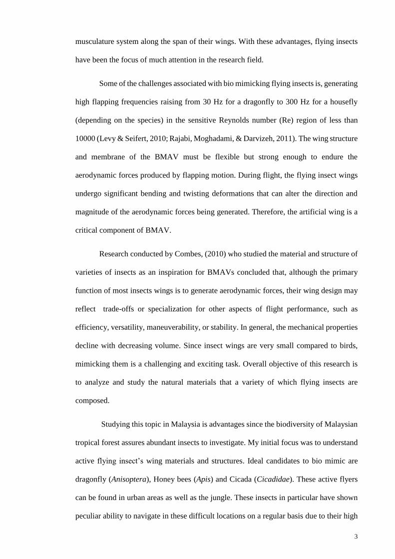
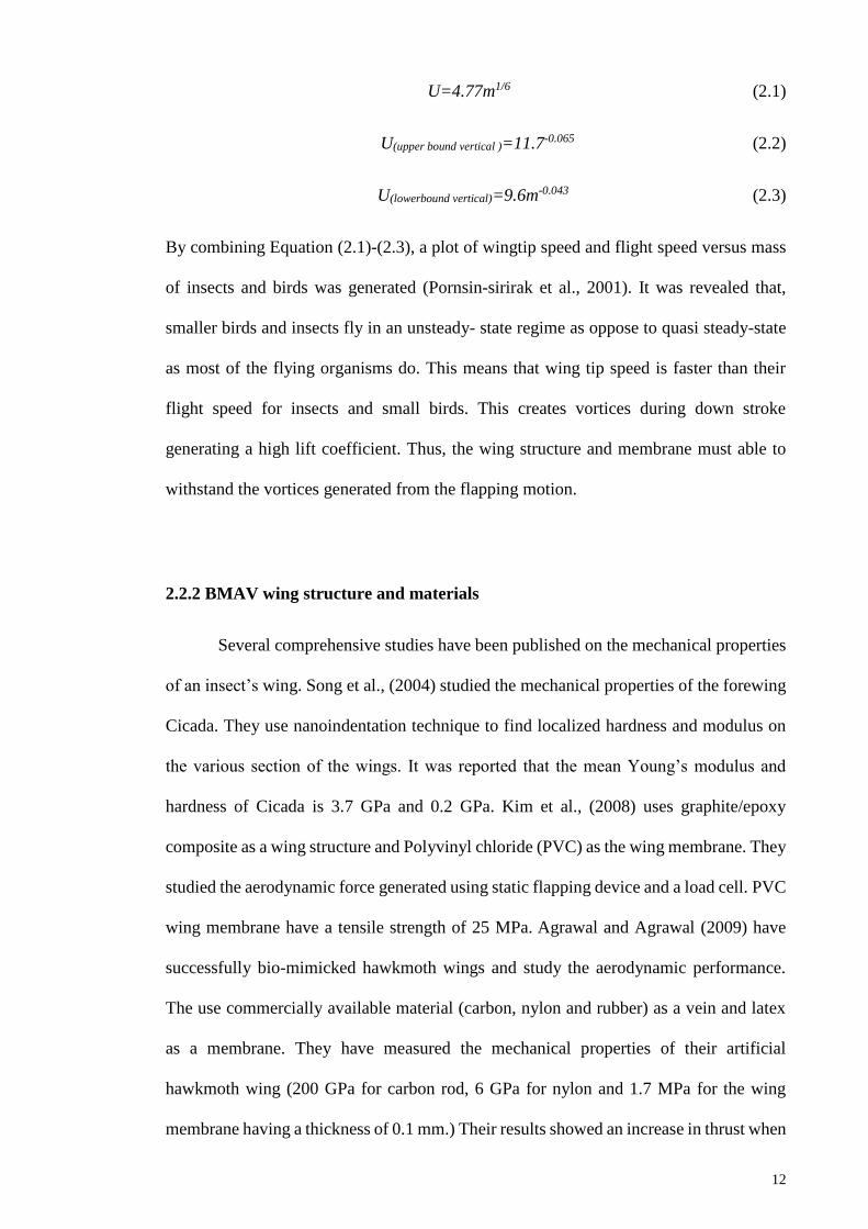
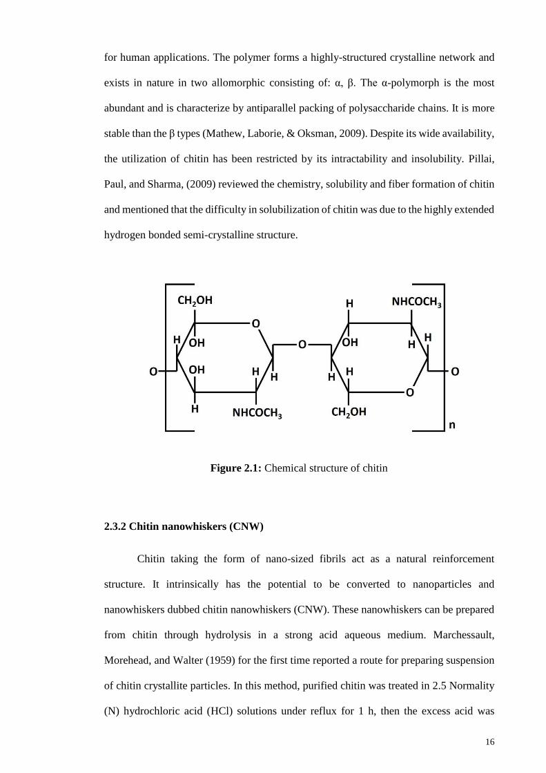
(Salaberria et al., 2015). Figure 2.1 shows the chemical structure of chitin. It is a long
chain polymer composed of 2-acetamide-2-deoxy-ᴅ-glucopyranose (GlcNAc) units
linked by β-(1-4) glycosidic bonds (Möller et al., 2004).
Muzzarelli, (2011) have examined the many potential benefits of chitin for
biomedical applications because of its sturdy mechanical properties and biocompatibility
16
for human applications. The polymer forms a highly-structured crystalline network and
exists in nature in two allomorphic consisting of: α, β. The α-polymorph is the most
abundant and is characterize by antiparallel packing of polysaccharide chains. It is more
stable than the β types (Mathew, Laborie, & Oksman, 2009). Despite its wide availability,
the utilization of chitin has been restricted by its intractability and insolubility. Pillai,
Paul, and Sharma, (2009) reviewed the chemistry, solubility and fiber formation of chitin
and mentioned that the difficulty in solubilization of chitin was due to the highly extended
hydrogen bonded semi-crystalline structure.
Figure 2.1: Chemical structure of chitin
2.3.2 Chitin nanowhiskers (CNW)
Chitin taking the form of nano-sized fibrils act as a natural reinforcement
structure. It intrinsically has the potential to be converted to nanoparticles and
nanowhiskers dubbed chitin nanowhiskers (CNW). These nanowhiskers can be prepared
from chitin through hydrolysis in a strong acid aqueous medium. Marchessault,
Morehead, and Walter (1959) for the first time reported a route for preparing suspension
of chitin crystallite particles. In this method, purified chitin was treated in 2.5 Normality
(N) hydrochloric acid (HCl) solutions under reflux for 1 h, then the excess acid was
17
removed, and then distilled water was added to obtain the CNW suspension. They found
that acid- hydrolyzed chitin spontaneously dispersed into a rod-like particles.
Instead of using chitin, which is insoluble to organic solution, the hydrolyzed chitin
(CNW) has potential as a reinforcing material for various application. Numerous articles
have been publish about the importance of CNW as a reinforcing material. Zeng et al.
(2012) reported that chitin whisker have a very high longitudinal and transverse modulus
of 150 and 15 GPa, respectively. Processing techniques have an important influence on
the final properties of nanocomposite. CNW can homogeneously disperse in water.
Therefore the best processing technique to make a nanocomposites is by dispersing CNW
in a polymer aqueous solution or polymer latex to obtain homogeneous dispersion. This
can then be casted in a container. By evaporation of water, a dried CNW based
nanocomposite can be obtained. Figure 2.2 illustrates the procedure for the preparation
of polymer/CNW nanocomposites. Casting evaporation is simple and economical. Most
of the recent work reported on the preparation of CNW based nanocomposites were
prepared by this method. Paillet and Dufresne (2001) reported using CNW to increase the
mechanical properties of thermoplastic. Gopalan Nair and Dufresne (2003a); Gopalan
Nair and Dufresne (2003b); Gopalan Nair et al. (2003) use crab shells and hydrolyze it to
produce CNW. This nanoparticles then dispersed into natural rubber to improve its
properties.

18
Figure 2.2: Procedure for the preparation of polymer/CNW nanocomposites by
casting-evaporating method
2.3.3 Chitosan
Chitosan is a biodegradable and biocompatible natural polysaccharide
composed of linear polysaccharide β- 1, 4 -linked 2-amine 2-deoxy- ᴅ - glucopyranoside
(GlcN) (Birolli, Delezuk & Campana-Filho, 2016). Figure 2.3 shows the chemical
structure of chitosan. The difference between chitosan and chitin is that, in chitin, the
GlcNAc units are largely predominant (>80%) while chitosan is richer in GlcN (>60%).
This difference in contents of GlcNAC and GlcN units is expressed as the average degree
of acetylation (DA). This strongly affects the arrangement of polymeric chain as well as
the physical and chemical properties (Domard, 2011). When the degree of deacetylation
of chitin reaches about 50% (depending on the origin of the polymer), it becomes soluble
in aqueous acidic media. The solubilization occurs by the protonation of the –NH2
function on the C-2 position of the ᴅ-glucosamine repeat unit. Chitosan is converted to a
polyelectrolyte in acidic media (Rinaudo, 2006).

19
Figure 2.3: Chemical structure of chitosan
Being soluble in aqueous solutions, it is largely used in applications such as;
solutions, gels, films and fibers. Chitosan has excellent film forming capability which
gives it great potential for use in many applications. However, the poor mechanical
properties of neat chitosan make it unsuitable for applications that needs durability and
strength.
2.3.4 Modification on chitosan
Chitosan is much easier to process than chitin, but the stability and mechanical
properties is generally lower. Chitosan is inclined to be much hydrophilic than chitin.
Various techniques have been developed to control the mechanical and chemical
properties. Chitosan can be crosslinked by many reagents. Wei et al., (1992) crosslinked
chitosan fibers with epichlorohydrin, Welsh and (2003) used diisocyanate as a
crosslinking agent for chitosan to improve the mechanical properties of hydrogels. Roy,
Todd and Glasser (1998) also use crosslinking method to enhanced the mechanical
properties of hydrogel by crosslinking chitosan with 1,4-butaediol diglycidyl.

20
Blends and nanomaterials have also been incorporated into chitosan matrix as
mentioned by Hirano, 2001. Also recent advances have been made by introducing carbon
nanotubes. Composite films exhibit a very significant increase of tensile modulus by
incorporating 0.8% of multiwalled carbon nanotubes into chitosan matrix (Wang et al.,
2005). Chitosan can be modified to have an improved mechanical properties while
retaining its biodegradability. A research conducted by Burger and Fredericksen (1948)
use carboxylic anhydrides with different chain lengths on chitosan yield chitosan based
derivatives that is totally insoluble in water with lower biodegradability. Besides these
blends, there are also reporting of chitosan being blended with cellulose, polyethylene,
polyvinyl chloride and polyvinylpyrrolidone(Hosokawa et al., 1990; Mucha, Piekielna,
& Wieczorek, 1999; Abou-Aiad et al., 2006).
2.3.5 Cellulose
Cellulose is the most abundant biopolymer in the world. Cellulose can be found
as a basic building block in plants, cotton and some marine creatures. Often this naturally
occurring cellulose takes the form of microfibrils that act as a natural reinforcing structure
(Moon et al., 2011). Since cellulose is the main building blocks for plants, its availability
almost inexhaustible and has a fascinating structure and properties. In fact cellulose
makes tree trunks strong enough to hold up the tallest trees. Some species of bacteria
even secrete cellulose to form a biofilm that act as a protective layer Figure 2.4 shows the
arrangement of fibrils, microfibrils and cellulose in cell walls.

21
Figure 2.4: arrangement of fibrils, microfibrils and cellulose in cell walls
Cellulose is another natural linear carbohydrate polymer. Cellulose consist of long
chain polysaccharide composed of β-1, 4 linked 2-amino-deoxy-β-ᴅ-glucan (Moon et al.,
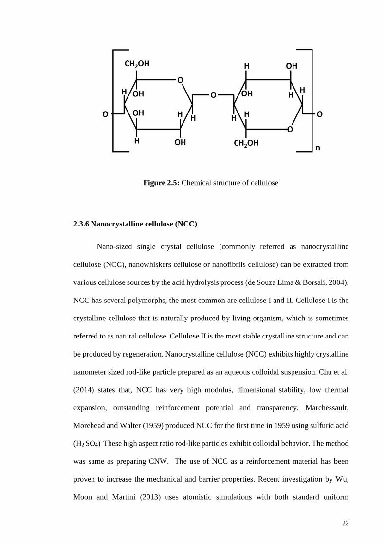
2011). Figure 2.5 shows the chemical structure of cellulose. Cellulose are known to have
an excellent reinforcement, renewable and biodegradable properties. The macrofibers of
cellulose in a plant are composed of microfibrils, which are formed by endless of
nanofibrils of cellulose. Interestingly, the nanofibrils of cellulose have crystal and
amorphous structures. The crystal part of cellulose cannot be broken due to strong
hydrogen bond of hydroxyl groups in cellulose. Moon et al. (2011) has gathered data and
elucidate that the fibrils can be generally separated into amorphous and/or crystalline
components, by mechanical or chemical enzymatic processes.
22
Figure 2.5: Chemical structure of cellulose
2.3.6 Nanocrystalline cellulose (NCC)
Nano-sized single crystal cellulose (commonly referred as nanocrystalline
cellulose (NCC), nanowhiskers cellulose or nanofibrils cellulose) can be extracted from
various cellulose sources by the acid hydrolysis process (de Souza Lima & Borsali, 2004).
NCC has several polymorphs, the most common are cellulose I and II. Cellulose I is the
crystalline cellulose that is naturally produced by living organism, which is sometimes
referred to as natural cellulose. Cellulose II is the most stable crystalline structure and can
be produced by regeneration. Nanocrystalline cellulose (NCC) exhibits highly crystalline
nanometer sized rod-like particle prepared as an aqueous colloidal suspension. Chu et al.
(2014) states that, NCC has very high modulus, dimensional stability, low thermal
expansion, outstanding reinforcement potential and transparency. Marchessault,
Morehead and Walter (1959) produced NCC for the first time in 1959 using sulfuric acid
(H2 SO4). These high aspect ratio rod-like particles exhibit colloidal behavior. The method
was same as preparing CNW. The use of NCC as a reinforcement material has been
proven to increase the mechanical and barrier properties. Recent investigation by Wu,
Moon and Martini (2013) uses atomistic simulations with both standard uniform

23
deformation approach and a complementary approach based on nanoscale indentation to
find the modulus of NCC. They reported that the modulus value to be 129.5 GPa which
is similar to Kevlar material. Another researcher, Dri et at. (2013) published an article on
cellulose in tandem arrangement and used quantum mechanics to compute the Young’s
modulus of NCC. It shows a high modulus value of 206 GPa, which is equivalent to steel.
Research into cellulose based films have gained considerable amount of attention.
Šimkovic (2013) mentioned that the colloidal behavior of NCC particles due to carboxyl
group introduced by air oxygen oxidation assure uniform and homogeneous settlement of
particles in a dry film. Leung et al. (2013) utilizes NCC as a reinforcing agent for plastic
and hydrogel by forming a percolation network and hydrogen bonding between the filler
material and the polymers. A chitosan-nanocellulose biocomposite film was prepared by
Dehnad et al. (2014) yields and enhanced thermal and biodegradable properties.
Elanthikkal et al. (2013) studied the effects of cellulose whisker loading into
poly(ethylene-co-vinyl acetate) matrix. The development of the composite film showed
superior thermal and mechanical properties then the pure counterpart.
2.4 Polymer crosslink
Polymers can be crosslinked to alter the chemical and physical properties. This
process initiated by inducing heat, pressure, change in pH and radiation on the polymer
matrix with the presence of crosslinking agent. When polymer chains are linked together
by these new links, they lose some of their ability to move as an individual polymer chains
resulting in compaction of structure. Figure 2.6 shows the illustration of crosslinking
process. This chemical process alters the stability and the properties of the polymer. Two
different reactions are associated with crosslinking: Schiff base or Michael-type adducts
(Kumar et al., 2004).

24
Figure 2.6: Illustration of crossliking process in a polymer; (1) Crosslinking agent is
introduced in polymer matrix, (2) Growth and branching, (3) Fully cured polymer
Crosslinking polymer matrix might give a positive or negative impact to the
polymer matrix depending on the dosage and compatibility. Research conducted by
Chambi and Grosso (2006) use transglutaminase as crosslinking agent for casein, gelatin
and casein–gelatin blend. Transglutaminase only reduce the water vapor barrier
properties. There was no changes on the mechanical properties for all the dosage. Sung
et al. (1999) studied the cytotoxicity effects of the naturally occurring crosslinker
(genipin) on biological tissue fixation. Glutaraldehyde is considered as one of the most
used crosslinking agent due to effectiveness. A study conducted by Bigi et al. (2006) on
the effects of Glutaraldehyde as a crosslinker for gelatin films. They reported,
Glutaraldehyde is very effective in reducing the swelling and thermal behavior of gelatin
film even with low amount of dosage. However, researchers tend look for alternative
crosslinking agents due to the fact that Glutaraldehyde is considered dangerous and toxic.
Usage of this crosslinking agent in a large scale might pose a threat to biosphere. Several
chemicals have been studied as alternative crosslinking agents. Muzzarelli (2009) created
chitosan hydrogel and examine the effects of genipin as a crosslinker for bio-medical and
pharmaceutical application. Some crosslinking agents such as citric acid need catalyst to
initiate crosslinking process. A study conducted by Reddy and Yang (2010) reported that

25
citric acid can be used as a crosslinker for starch film with the aid of sodium
hypophosphite.
2.4.1 Tannic acid
Tannic acid is extracted from plants and microorganisms. It is fully biodegradable
and less expensive to produce, compared to the other chemical derivatives. It has
polyphenolic compound containing a central carbohydrate core that is esterified by gallic
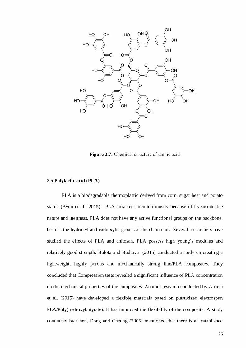
acids (Božič, Gorgieva & Kokol, 2012). Figure 2.7 shows the chemical structure of tannic
acid. Tannic acid has high molecular weight configuration and possess high antioxidant
capacity and can interact with other biological macromolecules (Shutava et al., 2005).
Several publisher has studied the effects of tannic acid as a crosslinker on polymer matrix.
Cao, Fu and He (2007) uses ferullic acid and tannic acid as a crosslinker gelatin
films.Despite its high potential, little has been published on the use of tannic acid as a
crosslinking agent for chitosan nanocomposites. Rivero, García and Pinotti (2010) studied
crosslinking capacity of tannic acid in chitosan film and stated that the moisture content
and solubility decreased. They also mentioned that the mechanical properties of chitosan
film increased.
26
Figure 2.7: Chemical structure of tannic acid
2.5 Polylactic acid (PLA)
PLA is a biodegradable thermoplastic derived from corn, sugar beet and potato
starch (Byun et al., 2015). PLA attracted attention mostly because of its sustainable
nature and inertness. PLA does not have any active functional groups on the backbone,
besides the hydroxyl and carboxylic groups at the chain ends. Several researchers have
studied the effects of PLA and chitosan. PLA possess high young’s modulus and
relatively good strength. Bulota and Budtova (2015) conducted a study on creating a
lightweight, highly porous and mechanically strong flax/PLA composites. They
concluded that Compression tests revealed a significant influence of PLA concentration
on the mechanical properties of the composites. Another research conducted by Arrieta
et al. (2015) have developed a flexible materials based on plasticized electrospun
PLA/Poly(hydroxybutyrate). It has improved the flexibility of the composite. A study
conducted by Chen, Dong and Cheung (2005) mentioned that there is an established

27
hydrogen bonding occurs between PLA and chitosan. They examined the effects of
PLA/chitosan blend using FTIR analysis.
PLA is one of the two most commonly used 3D printing materials (with the other
being ABS). This biodegradable material have the virtue of being odorless and doesn’t
warp significantly than other 3D printing materials. Due to its low melting point, using
PLA as a 3D printing material doesn’t require a heated bed. 3D printer can be used to
fabricate complex structures. Lin et al. (2014) studied the potential of utilizing 3D printing
technologies to fabricate bio-inspired shapes and successfully fabricated 3D printed
polymer based bio-inspired shapes. They mentioned that geometrically structured shapes
and design occurs naturally for a reason and possess enhanced, and often surprising,
mechanical properties, and provide inspiration for materials design. Kao et al. (2015)
fabricated PLA based scaffolds for bone tissue engineering using 3D printing technique.
They have fabricated high resolution scaffolds that is comparable to readily available
scaffolds by utilizing the advantages of PLA. Stansbury and Idacavage (2015) have
reviewed the possibilities of 3D printing to expand into conventional production method
for polymers. They mentioned that 3D printing technologies already altering many
industrial and academic operations due to their robustness and simplicity into fabrication
any design without the requiring molds or dies. Therefore it will be an interesting things
to study the possibilities of producing a 3D printed PLA based wing structure and evaluate
the performance of PLA as a BAV wing structure using 3D printer besides its promising
mechanical properties.

28
CHAPTER 3: RESEARCH METHODOGY
3.1 Introduction
This topic is divided into 4 sections. Each section describes the approaches
planned and implemented in this research work. The first step involved in the preparation
of the nanomaterials. Secondly the nanocomposite films was prepared. The third step
involved in fabricating BMAV wing structure and infusion of the film into the wing
structure. Finally the film is characterized through different series of test and its installed
performance as an artificial dragonfly wing membrane is analyzed.
3.2 Preparation of nanomaterial
Two types of nanomaterial (chitin and cellulose) have been prepared in this work.
Both nanomaterials have been incorporated into different batches of chitosan film to
investigate the effects of these nanomaterials in the chitosan matrix.
3.2.1 Preparation of CNW
Chitin based material was sourced from crab shell flakes. Chitin nanowhiskers
(CNW) were prepared using a acid hydrolysis method, as reported by (Gopalan Nair &
Dufresne, 2003). By incorporating this method, the amorphous structure of the chitin
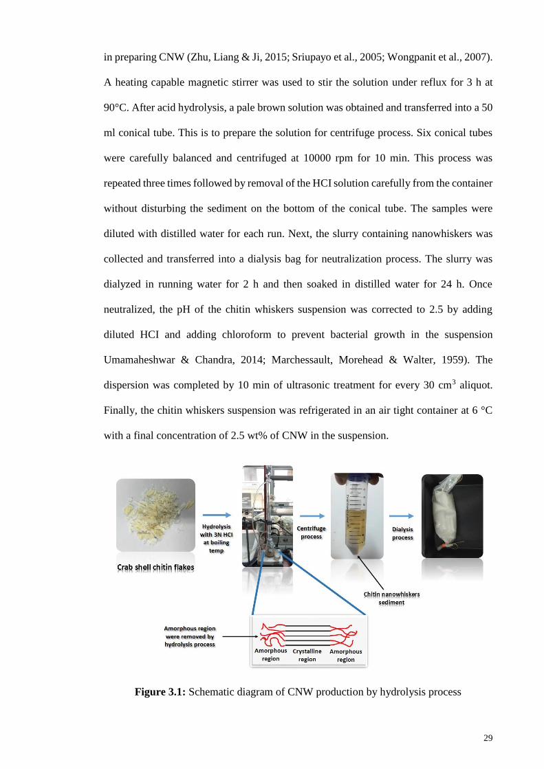
flakes will be removed. Figure 3.1 shows the schematic diagram of hydrolysis process
involved in producing CNW. The preparation begins by dispersing 5 g of chitin flakes
into 150 ml of a 3 N HCI solution in a flat bottom flask. A weight ratio of 1:30 was applied
29
in preparing CNW (Zhu, Liang & Ji, 2015; Sriupayo et al., 2005; Wongpanit et al., 2007).
A heating capable magnetic stirrer was used to stir the solution under reflux for 3 h at
90°C. After acid hydrolysis, a pale brown solution was obtained and transferred into a 50
ml conical tube. This is to prepare the solution for centrifuge process. Six conical tubes
were carefully balanced and centrifuged at 10000 rpm for 10 min. This process was
repeated three times followed by removal of the HCI solution carefully from the container
without disturbing the sediment on the bottom of the conical tube. The samples were
diluted with distilled water for each run. Next, the slurry containing nanowhiskers was
collected and transferred into a dialysis bag for neutralization process. The slurry was
dialyzed in running water for 2 h and then soaked in distilled water for 24 h. Once
neutralized, the pH of the chitin whiskers suspension was corrected to 2.5 by adding
diluted HCI and adding chloroform to prevent bacterial growth in the suspension
Umamaheshwar & Chandra, 2014; Marchessault, Morehead & Walter, 1959). The
dispersion was completed by 10 min of ultrasonic treatment for every 30 cm3 aliquot.
Finally, the chitin whiskers suspension was refrigerated in an air tight container at 6 °C
with a final concentration of 2.5 wt% of CNW in the suspension.
Figure 3.1: Schematic diagram of CNW production by hydrolysis process

30
3.2.2 Preparation of nanocrystalline cellulose (NCC)
Microcrystalline cellulose (MCC) was hydrolyzed with sulfuric acid (H2SO4) as
described by (Bondeson, Mathew & Oksman, 2006). Treatment of MCC with sulfuric
acid is done to produce isolated cellulose whiskers. Ehmann et al. (2014) reported that
hydrolysis of MCC introduce sulfate group. This surface esterification reaction is show
in figure 3.2. The first step begins by mixing 10.2 g of MCC with distilled water in a
beaker. The mixture was then put in an ice bath until a uniform cold environment is
establish within the beaker. Sulfuric acid were carefully added by drops to avoid
temperature spike since it is an exothermic process until the desired acid concentration of
63.5 wt% was reached. This optimized values of concentration and MCC mass was
reported by (Bondeson, Mathew & Oksman, 2006).
Figure 3.2: Schematic representation of the preparation of NCC starting from MCC
showing the surface esterification reaction introducing sulfate groups
31
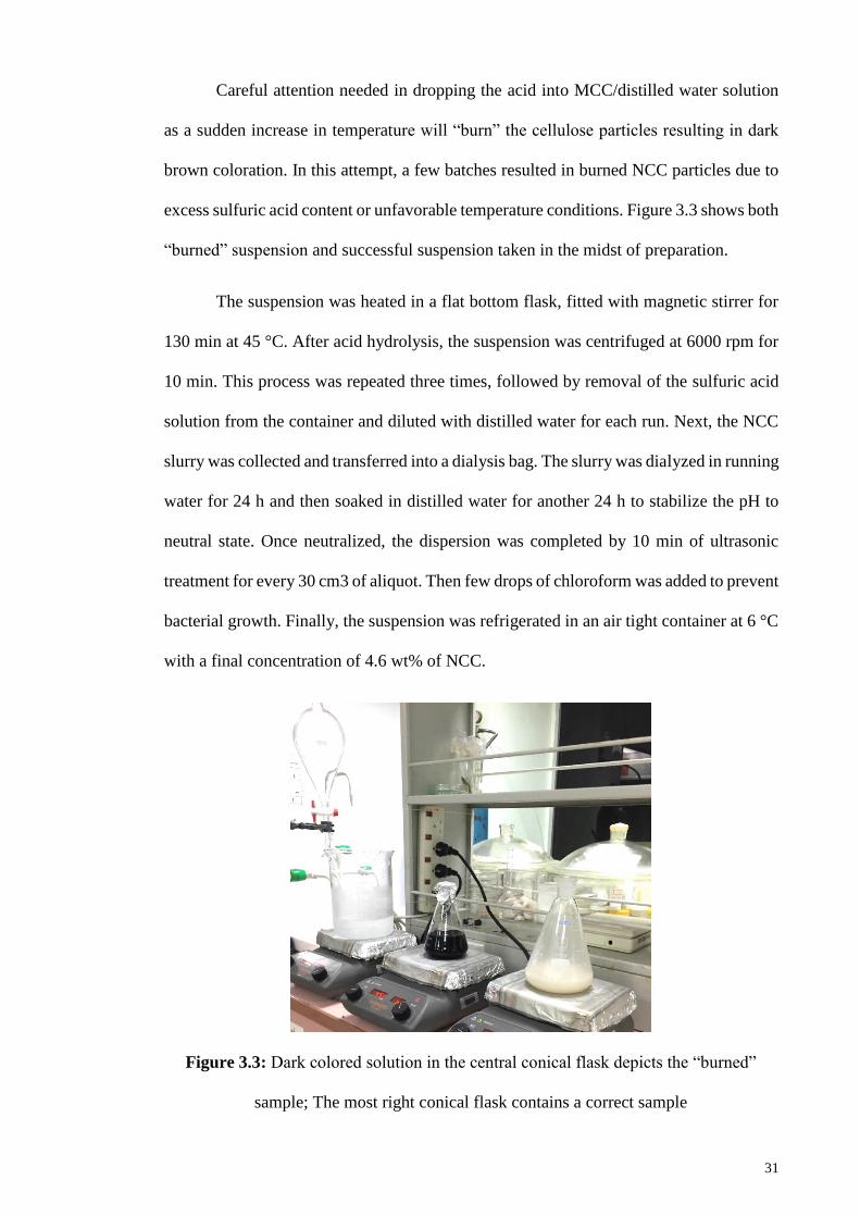
Careful attention needed in dropping the acid into MCC/distilled water solution
as a sudden increase in temperature will “burn” the cellulose particles resulting in dark
brown coloration. In this attempt, a few batches resulted in burned NCC particles due to
excess sulfuric acid content or unfavorable temperature conditions. Figure 3.3 shows both
“burned” suspension and successful suspension taken in the midst of preparation.
The suspension was heated in a flat bottom flask, fitted with magnetic stirrer for
130 min at 45 °C. After acid hydrolysis, the suspension was centrifuged at 6000 rpm for
10 min. This process was repeated three times, followed by removal of the sulfuric acid
solution from the container and diluted with distilled water for each run. Next, the NCC
slurry was collected and transferred into a dialysis bag. The slurry was dialyzed in running
water for 24 h and then soaked in distilled water for another 24 h to stabilize the pH to
neutral state. Once neutralized, the dispersion was completed by 10 min of ultrasonic
treatment for every 30 cm3 of aliquot. Then few drops of chloroform was added to prevent
bacterial growth. Finally, the suspension was refrigerated in an air tight container at 6 °C
with a final concentration of 4.6 wt% of NCC.
Figure 3.3: Dark colored solution in the central conical flask depicts the “burned”
sample; The most right conical flask contains a correct sample
32
3.3 Preparation of nanocomposite film
Chitosan based matrix were modified by two additives by both physical and chemical
modification. Physical additions were performed by incorporating nanoparticles and
chemical modification was carried out by introducing a crosslinking agent. Four separate
batches of chitosan based film were designed for this research work.
1. The effects of CNW on the chitosan matrix film (Batch 1)
2. The effects on NCC on the chitosan matrix film (Batch 2)
3. The effects of heat treatment on CNW based chitosan matrix film (Batch 3)
4. The effects of heat treatment on NCC based chitosan matrix film (Batch 4)
3.3.1 Preparation of chitosan nanocomposite film
Chitosan is soluble in acetic acid. The film forming solution was prepared by
weighing and adding 2 wt% of chitosan powder into a 2% (v/v) acetic acid solution under
rigorous magnetic stirring until chitosan powder completely dissolve into acetic acid
solution. A translucent pale yellow colored solution was obtain after 1 hour of stirring.
Then, nanomaterials were slowly added according to the ratio intended in the chitosan
solution. A high speed homogenizer was used for approximately 5 min to homogenize
the nanomaterials and chitosan matrix. Finally the mixture were stirred with magnetic
stirrer for an additional 1 h.
For further investigation, a crosslinking agent was introduced in chitosan film.
Chemical crosslinking was achieved by incorporating different amounts of tannic acid
into the chitosan solution. Tannic acid (20 mg and 40 mg per 1 g of chitosan) was
dispersed into the suspensions under vigorous magnetic stirring for another 1 h until it
was homogenized. The mixed suspension was cast onto a plastic Petri dish. Upon pouring

33
into the Petri dish, excess bubbles were seen in abundance. The casted suspensions were
left overnight in a dry cabinet to remove the bubbles and later evaporated in a drying oven
for 48 h to obtain dry composite films. The dry weigh taken from the Petri dish of each
samples was approximately ~ 0.4024 g each. All film have an average thickness of 100
micron +/- 10 micron.
3.3.2 Preparation of heat treated chitosan nanocomposite film
Heat treatment process was applied on the film to investigate its effect on
enhancing the film. There are two types of heat treatment; moist and dry (Ritthidej,
Phaechamud & Koizumi, 2002). The dry heat treatment method was used for our film.
Essentially, dry ambient air was simulated in a convection oven at 180°C. Films were
heat treated for 30 min at a uniform temperature of 180°C, resulting in a pale brown film
at the end of the heat treatment process.
3.4 Film nomenclature
Four sets of film were processed with different additives doses for batch 1 and 2.
Table 3.1 shows twelve types of film for Batch 1 (CNW) (Set I: neat chitosan film, serving
as the control sample; Set II: crosslinked chitosan film; Set III: chitosan film embedded
CNW; Set IV: crosslinked chitosan film embedded with CNW). Table 3.2 shows twelve
different types of film for Batch 2 (NCC) (Set I: neat chitosan film, as the control sample;
Set II: crosslinked chitosan film; Set III: chitosan film embedded NCC; Set IV:
crosslinked chitosan film embedded with NCC). For Batch 3 and 4, only Set I, Set II (A),
Set III (A) and Set IV (A) were chosen due to their minimal amount of additives in the
chitosan matrix. Letter “H” were assigned at the end of their label for heat treated samples.

34
Table 3.1: Nomenclature of chitosan nanocomposite for Batch 1
Sample Set Sample code Chitosan (%) CNW (%) Tannic acid
(mgTA/chitosan)
Set I Control 100
Set II A 100 20
B 100 40
Set III A 90 10
B 80 20
C 70 30
Set IV A 90 10 20
B 80 20 20
C 70 30 20
D 90 10 40
E 80 20 40
F 70 30 40
Table 3.2: Nomenclature of chitosan nanocomposite for Batch 2
Sample Set Sample code Chitosan (%) NCC (%) Tannic acid
(mgTA/chitosan)
Set I Control 100
Set II A 100 20
B 100 40
Set III A 90 10
B 70 30
C 50 50
Set IV A 90 10 20
B 70 30 20
C 50 50 20
D 90 10 40
E 70 30 40
F 50 50 40
3.5 BMAV wing membrane and wing structure
Dragonfly wings have a very complex and fine structure which is hard to replicate.
A simplified wing model was been created. This simplified dragonfly wing (for use on a
BMAV) was designed using the Solidworks computer aided design (CAD) software and
transferred into 3D printer compatible file. A MakerBot Replicator 2X experimental 3D

35
printer was configured to “fine printing method” for this research since the sample size is
in the vicinity of 8 cm with a thickness of 0.5 mm. Both fore and hind wing were
fabricated using bio-based Polylactic Acid (PLA). Figure 3.4 shows the 3D model of a
simplified dragonfly wing structure and the fabricated wing model.
(a) (b)
(c) (d)

36
(e)
Figure 3.4: 3D model of simplified dragon wing structure, (a) Top view fore wing;
(b) Iso view forewing; (c) Top view hind wing; (d) Iso view of hind wing; (e)
Fabricated dragonfly wing
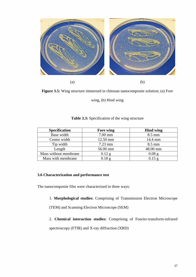
Once the wing structure was printed out, the exposed top surface layer required
sanding to remove jagged material remaining on the structure. The structures were then
submerged in one of the selected chitosan nanocomposite film solutions in a Petri dish.
Figure 3.5 shows the wing structure in the solution. A drying time of 48 h was required.
Specifications of the wings are listed in Table 3.3.
37
(a) (b)
Figure 3.5: Wing structure immersed in chitosan nanocomposite solution; (a) Fore
wing, (b) Hind wing
Table 3.3: Specification of the wing structure
Specification Fore wing Hind wing
Base width 7.00 mm 8.5 mm
Centre width 12.50 mm 14.4 mm
Tip width 7.23 mm 8.5 mm
Length 56.00 mm 48.00 mm
Mass without membrane 0.12 g 0.08 g
Mass with membrane 0.18 g 0.15 g
3.6 Characterization and performance test
The nanocomposite film were characterized in three ways:
1. Morphological studies: Comprising of Transmission Electron Microscope
(TEM) and Scanning Electron Microscope (SEM)
2. Chemical interaction studies: Comprising of Fourier-transform-infrared
spectroscopy (FTIR) and X-ray diffraction (XRD)

38
3. Performance testing: Mechanical test by Universal Testing Machine (UTM),
physicochemical performance, Contact angle (wettability), Optical transmittance
(UV-visible spectrophotometer) and nanoindentation test
The complete BMAV wings were tested to examine their nanomechanical
properties and compared to actual dragonfly wing. Aeroelastic properties were examined
using static flapping generator at variable flapping frequency. High speed frame camera
was used to capture and analyze behavior pattern of BMAV wings and compared to actual
dragonfly wings. Section 3.6.1 to 3.6.10 describes characterization method and
parameters used in this research.
3.6.1 Morphological studies by Transmission Electron Microscope (TEM)
Transmission electron microscopy is a microscopy technique in which a beam of
electrons is transmitted through thin specimen. The beam of electrons interacts with the
specimen to create digital noise. This image can be magnified in a nanometer scale
through a charge-coupled device creating a digital image that has a very high resolution.
TEM can be utilized to examine the structure of nano-scaled material. For this work,
nanoparticles produced from laboratory were analyzed using TEM. Two types of
nanomaterials (CNW and NCC) were examined using a Zeis EFTEM Libra 120 TEM.
The size and morphological structure of CNW and NCC were examined. The procedure
begins by extracting a few drops from the samples that were collected from the preserved
nanomaterial storage (in the chiller). The samples were dispersed in distilled water to
reduce the opacity of the nanomaterial solution, followed by ultrasonic treatment. The
samples were dropped in carbon coated copper grid and stored in dry cabinet 48 h prior
of TEM examination. High magnification images were produced to examine the
morphological aspects of the nanomaterials.

39
3.6.2 Morphological studies by Scanning Electron Microscope (SEM)
Scanning electron microscope principle is similar to TEM. The electron beam is
generally scanned in a raster scan pattern. This electron microscope scans the surface of
a sample to produce samples topography and composition. Generally, SEM requires the
samples to be coated with gold powder using sputter machine. This is to ensure the sample
is electrically conductive and helps to produce details of samples surface. Dried chitosan
nanocomposite films were examined using Zeiss Evo MA10 Scanning Electron
Microscope. The dispersion and the blending effects of NCC and tannic acid in the
chitosan matrix were studied. Films were cut in a samples of 10 X 10 mm. The film
surface and cross sectional area were examined at a magnification of 2.0 K (2 μm). Liquid
nitrogen were used to force fracture the film as described by (Lorevice et al., 2016).
Figure 3.6 shows film samples with gold coating. All samples were coated with a fine
layer of gold to create an electrical conductive layer on the film surface and thereby
produce a sharper and clear image.
Figure 3.6: SEM film samples coated with gold prior viewing

40
3.6.3 Chemical interaction studies by Fourier-transform-infrared spectroscopy
(FTIR)
Fourier Transform Infrared Spectroscopy (FTIR) identifies the chemical bonding
in a molecule. This is done by emitting infrared radiation through a sample. Some of the
infrared radiation is absorbed by the sample and some of it is passed through
(transmitted). The resulting spectrum represents the molecular absorption and
transmission, creating a molecular fingerprint of the sample. The resulting produce a
profile of the sample, a distinctive molecular fingerprint that can be used to screen and
scan samples for many different components. FTIR is an effective analytical instrument
for detecting functional groups and characterizing covalent bonding information. FTIR
test were performed for this work using Perkin Elmer Spectrum 400 FT-IR/FT-FIR
spectrometer. This test was done to reveal the chemical interactions between the chitosan
matrix, nanomaterials and tannic acid. All samples were first cut into 15 X 15 mm and
stored in dry cabinet. A total of 32 scans were performed for each sample at a resolution
of 4 cm-1. Measurements were recorded at a wavelength range between 4000 and 400
cm-1.
3.6.4 Chemical interaction studies by X-ray diffraction (XRD)
The XRD technique used for identifying the atomic and molecular structure of a
crystal. The sample is illuminated with x-rays of a fixed wave-length and the intensity of
the reflected radiation is recorded using a goniometer. The crystalline atoms cause a beam
of incident X-rays to diffract into many specific directions. This unique representation of
angles and intensities used for phase identification of a crystalline material and can
provide information on unit cell dimensions. Analysis for all samples were performed
using an X-ray diffractometer (Siemens D5000). Samples were cut into 15 x 15 mm and

41
adhered to a microscope glass side using double-sided tape. This is to ensure all samples
have a smooth flat surface prior to test. The X-ray diffractometer machine is equipped
with a Cu Kα radiation source (k=1.540600 Å) operating at 40 kV and 40 mA (at room
temperature). The relative intensity was recorded in the scattering range of (2θ) 5-80°
with a step size of 0.1°.
3.6.5 Performance testing using Universal Testing Machine (UTM)
Mechanical properties were analyzed for all films using a Shimadzu AGS-X series
tensile tester machine according to the ASTM D882-02 method. A low capacity load cell
(100 N) was used to increase the sensitivity of break due to the film thickness. Films were
preconditioned in a dry cabinet 48 h before testing. A crosshead speed of 1 mm/min was
used for each test. According to the principle of tensile testing, the material strain can be
taken as:
ε= Δl/l0 (3.1)
Where Δl is the increase of length in the tensile force direction and l0 is the original sample
gauge length. Correspondingly, the material stress can be calculated as follows:
σ= F/A0 (3.2)
Where F is the tensile force applied on the sample and A0 is the cross-sectional area of
the sample. By employing Hooke’s law, the Young’s modulus of the material is:
E= σ/ ε (3.3)
Due to the non-linear characteristics of biomaterials, the elastic force and
deformation do not exhibit a clearly defined elastic limit. Thus, offset method was used
to compensate errors. The amount of 0.02% is set off on the extension axis, and a line is

42
drawn parallel to the straight line portion of the loading curve. By this principle, Tensile
strength, Young’s modulus and elongation at the break were calculated. At least 5 samples
were tested for each film.
3.6.6 Performance testing by physicochemical test
The chitosan nanocomposite films moisture uptake and solubility were tested
using laboratory test rig. Firstly, the film was cut into 15 x 12 mm pieces. Then the film
samples were weighed to the nearest 0.0001 g in a dry state after heating in oven at 105
°C for 1.5 h. Moisture uptake was measured by immersing dried film pieces in 75 ml of
distilled water (under constant agitation) for 1 h at 25 °C with a relative humidity of 60
RH. Then samples were recovered and dried with filter paper to remove excess surface
water and weighed again. The average value of water uptake was calculated using
Equation (3.4).
% water uptake = 100)(
i
is
W
WW (3.4)
Where Ws is the weight of the swollen sample and Wi is the weight of the sample after
heating it in a convection oven to make sure the film is in a completely dry state.
Immediately after recording the swollen weight, the samples were dried again in
a convection oven at 105 °C for at least 1 h 30 min until it reaches a constant dry weight.
The samples were weighted to the nearest 0.0001 g. This dry weight was then used in
Equation (3.5) to find the solubility:
% solubility = 100dry weight initial
dry weight finaldry weight initial
(3.5)
43
3.6.7 Performance testing by water contact angle test
Measurement of the water contact angle on the film surface reveals the wettability
of the film. Selected film samples were prepared for this test using the Dataphysics
Tensiometer Model OCA 15EC. Samples were prepared as described in section 3.3.4 and
preconditioned in dry cabinet before test. Needle tip dispersion were set to 2 μL. Distilled
water was used as a liquid medium. The contact angle was measured were captured after
5 s after water contact was established. At least 3 repetitions were performed for each
sample to collect the average value.
3.6.8 Performance testing by optical transmittance
Optical transmittance and visible light transparency tests were carried out to
investigate the effects of tannic acid and nanomaterials in terms of optical performance.
The UV-visible spectrophotometer Cary 50 Probe were used to extract the data of optical
transmittance (Tr) for selected film samples. An optical wavelength band of 200 -800 nm
was set prior to examining the samples. A generic digital camera with manual mode were
set at a minimum focus point distance vertically with a letter ‘Samples” written on the
table. Film samples were placed evenly on top of the letter and images were captured to
analyze the visible light transparency of the film.
3.6.9 Performance testing by electromagnetic actuated flapping wing mechanism
Flapping wing mechanism was powered by a 12 V DC connected to a LM555
crystal clock oscillator integrated circuit that generates a stable oscillatory motion. The
flapping frequency can be adjusted with a 22 kW potentiometer. Figure 3.7 shows the
mechanism assembly. The wing structure was glued to an iron plate (2 mm long 2.75 mm

44
thick) at the base part, which mimics the dragonfly joint. The iron plate was then glued
to an electromagnetic actuator, which is able to create a linear up- downstroke motion at
a variable wing beat frequency up to 250 Hz.
Two high frame rate cameras (Phantom Micro 310 by vision research) were used
to precisely capture the flapping wing motion. The resolution of the camera was set at
320 x 240 pixels. This low resolution is needed in order to capture smooth motion at
35000 Frame per Second (FPS). High powered Light Emitting Diode (LED) lighting was
used to maximize the video brightness due to a higher lens aperture (Nikon FX lens) and
high frame rate. Two cameras were placed perpendicular to each other in order to
determine the three- dimensional shape and orientation of the wing surface as reported by
(Gui et al., 2010). Data was collected for one complete wing stroke for 30 Hz (dragonfly
natural flapping frequency), 60 Hz and 120 Hz (resonant frequency). Wing tip deflection,
bending angle and wing tip twist angle were analyzed using Vision Research Phantom
Camera Control Software (version 2.6.749.0).
Figure 3.7: Flapping wing mechanism setup

45
3.6.10 Performance testing by nanoindentation test
Complete wing design (PLA based structure and selected chitosan composite) and
actual dragonfly wings were tested using Hysitron TI 750 UBI nanoindenter machine.
Five points on a simplified BMAV wing and actual dragonfly wing were examined based
on the crucial part in a wing structure as mentioned by (Sun & Bhushan, 2012). Average
values of hardness and modulus of actual dragonfly wing and simplified BMAV wing
were acquired using a fixed displacement method using Berkovich indenter instead of
Vickers pyramid. The Berkovich indenter is a good choice for standard testing because it
produces plasticity at very low loads, and minimizes the influence of friction. According
to the theory on nanoindentation test (Oliver & Pharr, 1992; Joslin & Oliver, 1990; Saha
& Nix, 2002) the reduced modulus is expressed as:
𝐸𝑟 =√𝜋
2𝛽
𝑆
√𝐴 (3.6)
Where S is the contact stiffness that is defined by S=(dP/dh)unload and β is coefficient of
Berkovich tip β =1.034. The load and displacement during indentation process are
analyzed to obtain the contact area. The contact area, A is related to the contact depth hc
as:
𝐴 = ∑ (𝐶𝑛ℎ𝑐1/2𝑛−1
)8
𝑛=0 (3.7)
Where Cn are constant depending on the indenter and given by machine calibration. In
Equation (3.7) hc is determined by:
ℎ𝑐 = ℎ𝑚𝑎𝑥 − 𝜀𝑃𝑚𝑎𝑥
𝑆 (3.8)
For the Berkovich tip, ε = 0.75 is a constant. The relationship between indentation load,
P, and penetration depth, h, is as shown in Figure 3.8. Maximum load Pmax and maximum
penetration depth hmax were recorded automatically by the indenter. From equation (3.6)-

46
(3.7) we can obtain the reduced modulus Er. The effects of a non-rigid indenter on the
load displacement behavior can be consider by defining an effective modulus Er, as
follows:
1
𝐸𝑟=
1−𝑣2
𝐸+
1−𝑣𝑖2
𝐸𝑖 (3.9)
Where E is the Young’s modulus and ν is the Poisson’s ratio of the specimen. Ei and νi
are the values from the indenter. Using diamond tip on the indenter the value for Ei is
1141 GPa and vi as 0.07 respectively. Poisson’s ratio of the specimen is taken as 0.3 by
default. The hardness of the material is defined by:
𝐻 =𝑃𝑚𝑎𝑥
𝐴 (3.10)
From equation (3.6)-(3.10), the modulus and the hardness of the samples can be obtained.
Figure 3.8: Graph of indention load P; Penetration depth h; showing the process of
loading and unloading of the nanoindenter.
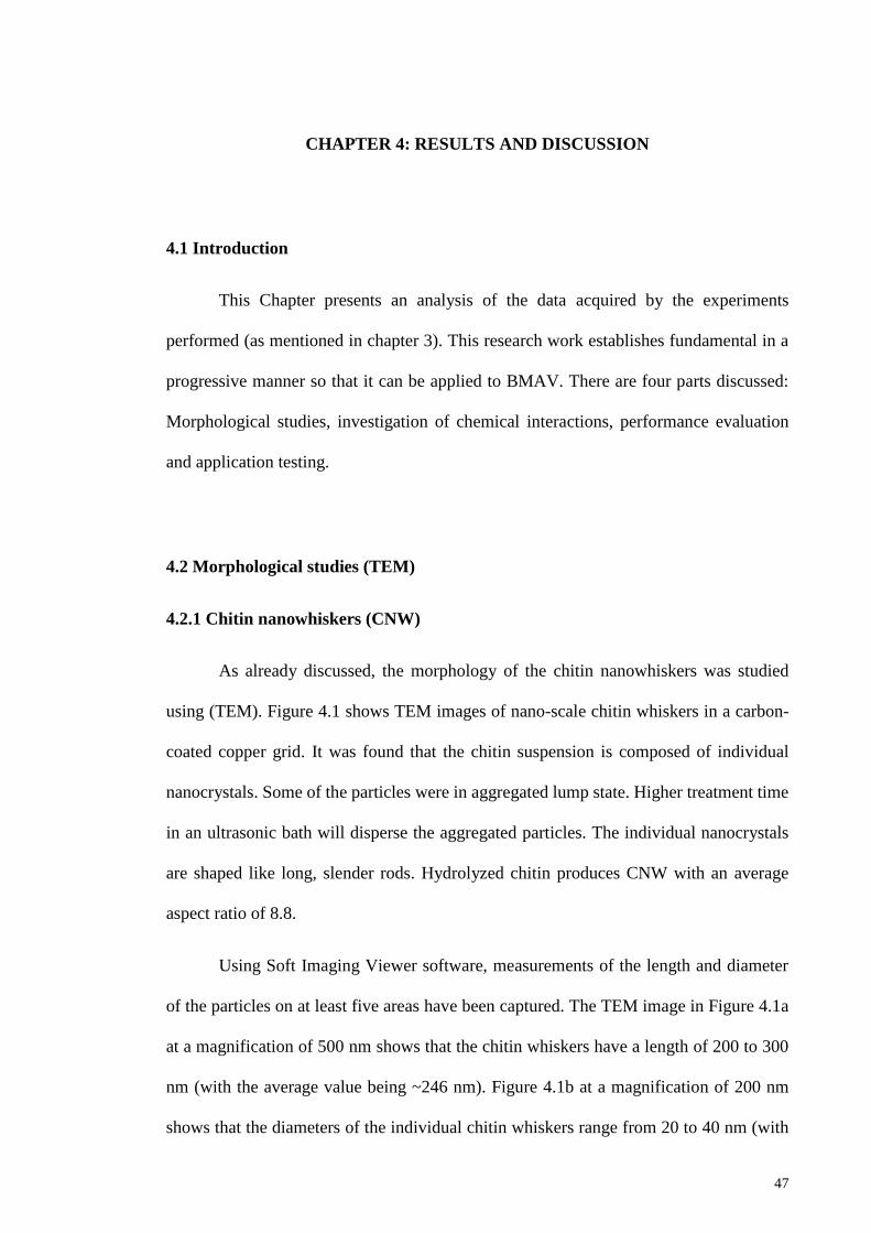
47
CHAPTER 4: RESULTS AND DISCUSSION
4.1 Introduction
This Chapter presents an analysis of the data acquired by the experiments
performed (as mentioned in chapter 3). This research work establishes fundamental in a
progressive manner so that it can be applied to BMAV. There are four parts discussed:
Morphological studies, investigation of chemical interactions, performance evaluation
and application testing.
4.2 Morphological studies (TEM)
4.2.1 Chitin nanowhiskers (CNW)
As already discussed, the morphology of the chitin nanowhiskers was studied
using (TEM). Figure 4.1 shows TEM images of nano-scale chitin whiskers in a carbon-
coated copper grid. It was found that the chitin suspension is composed of individual
nanocrystals. Some of the particles were in aggregated lump state. Higher treatment time
in an ultrasonic bath will disperse the aggregated particles. The individual nanocrystals
are shaped like long, slender rods. Hydrolyzed chitin produces CNW with an average
aspect ratio of 8.8.
Using Soft Imaging Viewer software, measurements of the length and diameter
of the particles on at least five areas have been captured. The TEM image in Figure 4.1a
at a magnification of 500 nm shows that the chitin whiskers have a length of 200 to 300
nm (with the average value being ~246 nm). Figure 4.1b at a magnification of 200 nm
shows that the diameters of the individual chitin whiskers range from 20 to 40 nm (with
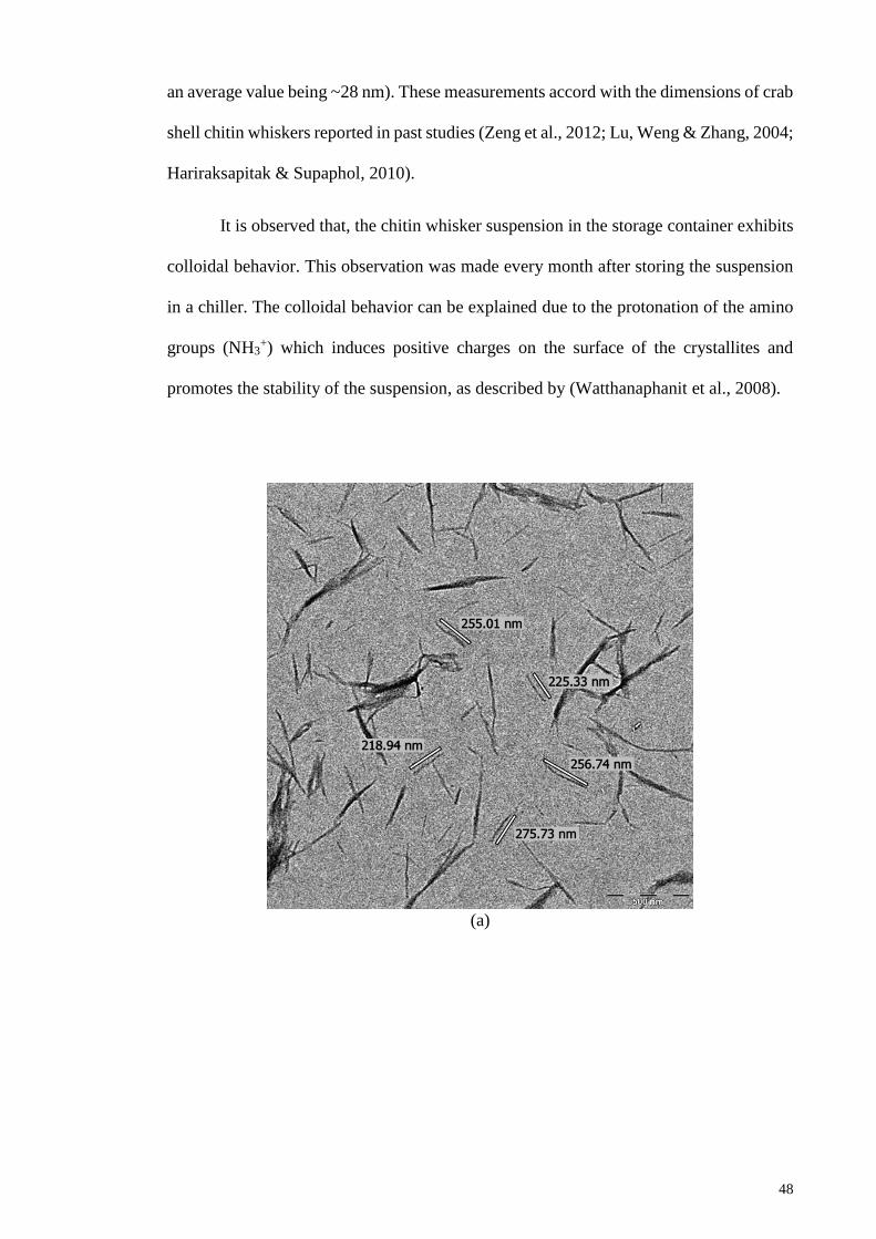
48
an average value being ~28 nm). These measurements accord with the dimensions of crab
shell chitin whiskers reported in past studies (Zeng et al., 2012; Lu, Weng & Zhang, 2004;
Hariraksapitak & Supaphol, 2010).
It is observed that, the chitin whisker suspension in the storage container exhibits
colloidal behavior. This observation was made every month after storing the suspension
in a chiller. The colloidal behavior can be explained due to the protonation of the amino
groups (NH3+) which induces positive charges on the surface of the crystallites and
promotes the stability of the suspension, as described by (Watthanaphanit et al., 2008).
(a)
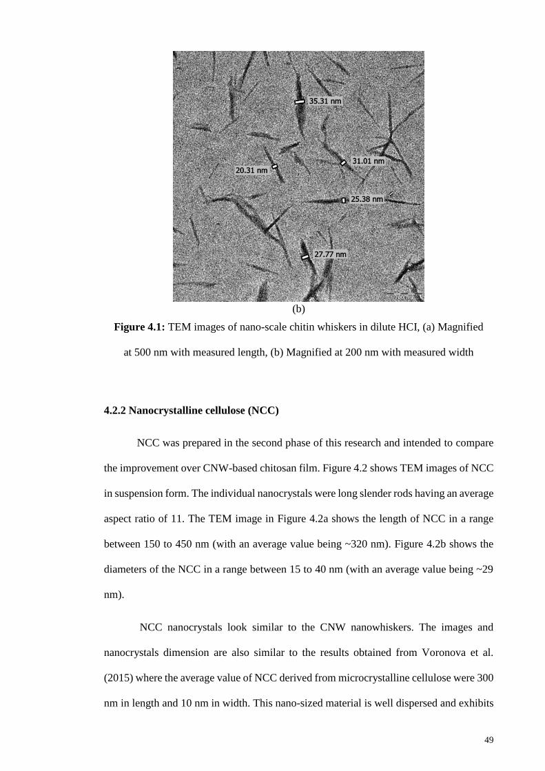
49
(b)
Figure 4.1: TEM images of nano-scale chitin whiskers in dilute HCI, (a) Magnified
at 500 nm with measured length, (b) Magnified at 200 nm with measured width
4.2.2 Nanocrystalline cellulose (NCC)
NCC was prepared in the second phase of this research and intended to compare
the improvement over CNW-based chitosan film. Figure 4.2 shows TEM images of NCC
in suspension form. The individual nanocrystals were long slender rods having an average
aspect ratio of 11. The TEM image in Figure 4.2a shows the length of NCC in a range
between 150 to 450 nm (with an average value being ~320 nm). Figure 4.2b shows the
diameters of the NCC in a range between 15 to 40 nm (with an average value being ~29
nm).
NCC nanocrystals look similar to the CNW nanowhiskers. The images and
nanocrystals dimension are also similar to the results obtained from Voronova et al.
(2015) where the average value of NCC derived from microcrystalline cellulose were 300
nm in length and 10 nm in width. This nano-sized material is well dispersed and exhibits
50
colloidal behavior. The usage of sulfuric acid for hydrolysis process produces NCC with
sulfate ester group resulting in electrostatic repulsion among the negatively charged
sulfate ester group that promotes good dispersion in the NCC suspension as mentioned
by (Zhong et al., 2012; Dong & Gray, 1997).
(a)
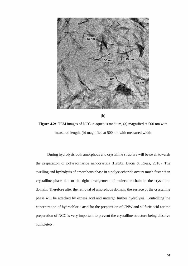
51
(b)
Figure 4.2: TEM images of NCC in aqueous medium, (a) magnified at 500 nm with
measured length, (b) magnified at 500 nm with measured width
During hydrolysis both amorphous and crystalline structure will be swell towards
the preparation of polysaccharide nanocrystals (Habibi, Lucia & Rojas, 2010). The
swelling and hydrolysis of amorphous phase in a polysaccharide occurs much faster than
crystalline phase due to the tight arrangement of molecular chain in the crystalline
domain. Therefore after the removal of amorphous domain, the surface of the crystalline
phase will be attacked by excess acid and undergo further hydrolysis. Controlling the
concentration of hydrochloric acid for the preparation of CNW and sulfuric acid for the
preparation of NCC is very important to prevent the crystalline structure being dissolve
completely.

52
4.3 Morphology studies (SEM)
A scanning electron microscope (SEM) was employed to inspect selected NCC
based chitosan nanocomposite film. SEM reveals the homogeneity of the composite, the
dispersion level of the nanocomposite film within the chitosan matrix and possible visible
changes due to crosslinking effects. Both surface and cross-sectional areas were
examined. Figure 4.3(a-d) shows a SEM micrograph of the film surface. Figure 4.3(e-h)
shows a SEM micrograph of the fractured cross-section of the chosen films Set I, Set II
(B), Set III (C) and Set IV (F) for the NCC based chitosan nanocomposite. Pure chitosan
film serves as a control film (Set I) in Figure 4.3a. It appears to be a smooth and have a
homogeneous surface, which indicates good miscibility in the aqueous media. However
when tannic acid were introduced as a crosslinker, the chitosan film (shown in Figure
4.3b) leads to the formation of a more rough and porous surface. Addition of NCC (in
Figure 4.3c) in the film reveals a formation of more ridges and an uneven surface. Also
observed, dense, white, rod-like shape structures appear scattered in the Set III (C) film.
This structure corresponds to the cellulose nanocrystals as reported by (Azizi Samir,
Alloin & Dufresne, 2005). However, the SEM image of the Set IV (F) film which has
tannic acid (in Figure 4.3d) shows less roughness and a more homogenized structure,
when compared to film Set III (C). This is due to the role played by tannic acid as a
crosslinker which interacts with the NCC and chitosan matrix (as seen in FITR spectra)
to form a compact formation.
The cross-sections in, Figure 4.3e and 4.3f of Set I and Set II (B) are not much
difference, except for differences in roughness and the appearance of cracks. However,
both Figures 4.3g and 4.3h show increased surface roughness and fiber-like formations.
This indicates aggregation of NCC and phase separation occurrence for the Set III (C)
and Set IV (F) films. Similar results have been obtained by (Zhao et al., 2014). They
postulated that their sample’s SEM image shows that the addition of NCC caused drastic

53
changes in the film’s microstructure. The addition of tannic acid makes the film more
rough and porous. SEM analysis further clarifies and supports that the mechanical and
water resistivity properties have been improved, due to the introduction of NCC and
tannic acid.
(a) (e)
(b) (f)
(c) (g)
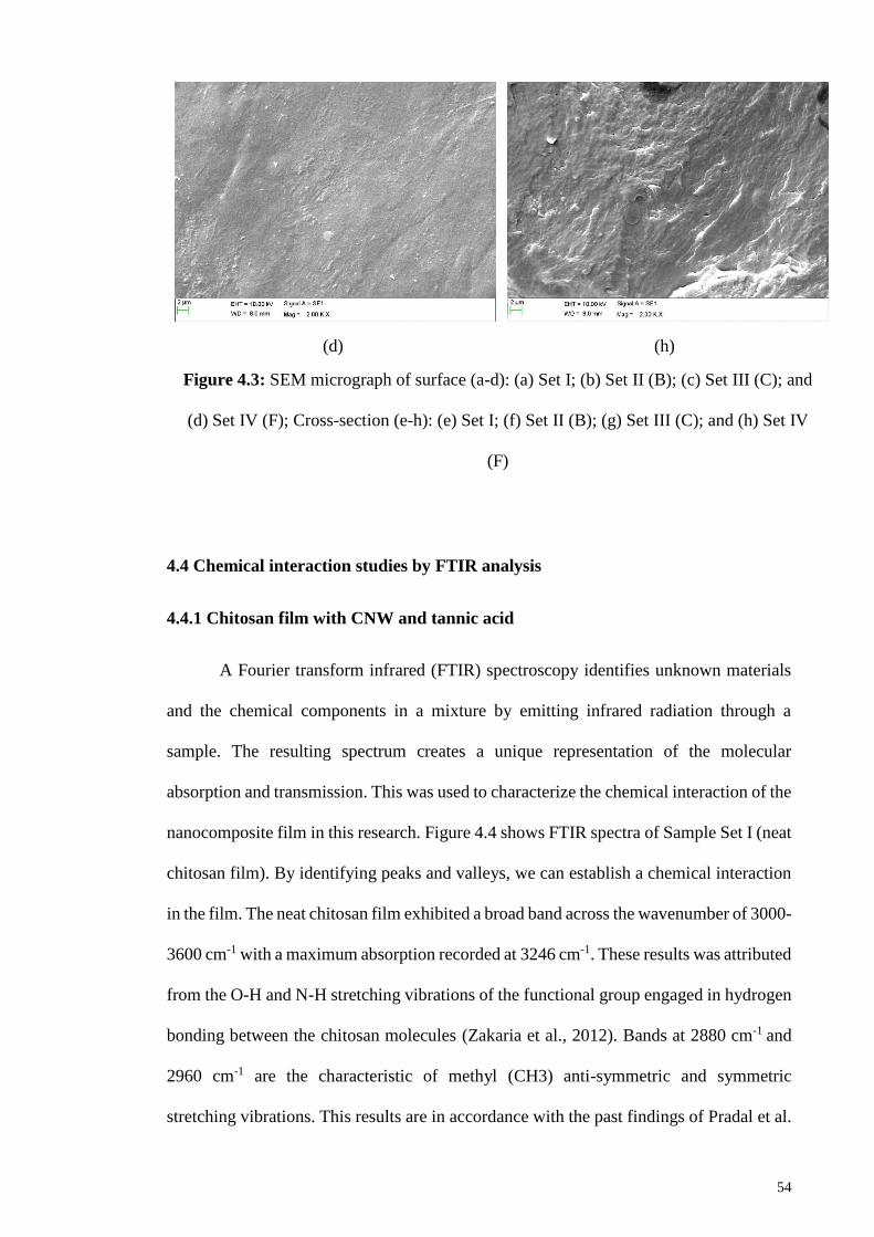
54
(d) (h)
Figure 4.3: SEM micrograph of surface (a-d): (a) Set I; (b) Set II (B); (c) Set III (C); and
(d) Set IV (F); Cross-section (e-h): (e) Set I; (f) Set II (B); (g) Set III (C); and (h) Set IV
(F)
4.4 Chemical interaction studies by FTIR analysis
4.4.1 Chitosan film with CNW and tannic acid
A Fourier transform infrared (FTIR) spectroscopy identifies unknown materials
and the chemical components in a mixture by emitting infrared radiation through a
sample. The resulting spectrum creates a unique representation of the molecular
absorption and transmission. This was used to characterize the chemical interaction of the
nanocomposite film in this research. Figure 4.4 shows FTIR spectra of Sample Set I (neat
chitosan film). By identifying peaks and valleys, we can establish a chemical interaction
in the film. The neat chitosan film exhibited a broad band across the wavenumber of 3000-
3600 cm-1 with a maximum absorption recorded at 3246 cm-1. These results was attributed
from the O-H and N-H stretching vibrations of the functional group engaged in hydrogen
bonding between the chitosan molecules (Zakaria et al., 2012). Bands at 2880 cm-1 and
2960 cm-1 are the characteristic of methyl (CH3) anti-symmetric and symmetric
stretching vibrations. This results are in accordance with the past findings of Pradal et al.

55
(2011). Pure chitosan film also exhibits distinctive absorption bands at 1640 cm-1 (C=O
stretching in amide group, amide I band) and 1542 cm-1 (NH bending vibration in amide
group). An absorption band at 1152 cm-1 is the characteristic of anti-symmetric stretching
of the C-O-C bridge and 1024 cm-1 is the vibration involving C-O group stretching of the
chitosan film as reported in (Pawlak & Mucha, 2003).
Figure 4.4: FTIR absorption spectra of pure chitosan film (Set I)
Figure 4.5a shows the changes occurred when CNW were added into chitosan
matrix (Set III A, B and C). Film Set III C were analyzed since it has the highest
nanomaterial dosage. This film exhibited a split peaks at 1654 cm-1 and 1618 cm-1. These
changes were attributed to the stretching of C=O stretching amide I O=C-NH-CH3
(signature of α chitin). Traces of chitin validated by the N-H bond of N-acetyl group
(amide II) were observed at 1556 cm-1 as observed by (Saravanan, Hemalatha & Sudha,
2011). The peaks at 3424 cm-1 and 3259 cm-1, shows a shift to a higher wave numbers
when compared to the neat chitosan (Set I) film spectra. Past reporting relates these peaks
with O-H and N-H stretching vibrations (Ifuku, Shervani & Saimoto, 2013). These

56
observations indicate that there is good miscibility between the chitin whiskers and the
chitosan matrix.
The addition of tannic acid reveals some changes on the chemical interaction in
the chitosan matrix. Spectra of film Set II (B) (Figure 4.5b) showed a band peak located
at 1549 cm-1, which is due to the symmetrical deformation of NH3+ resulted from
ionization of the primary amine group in the presence of carboxylic group. This is caused
by dissociative interactions between chitosan and tannic acid under acidic conditions. A
weak band at 1364 cm-1 replaces the band at 1320 cm-1 from neat chitosan (Set I) spectra.
The 1068 cm-1 band (attributed to the C-O-C bonding vibration) and the 1338 cm-1 band
both disappear, when compared to the neat chitosan (Set I) film spectra. These changes
indicate that, there is an interactions between the chitosan amino group and the carboxyl
group located in tannic acid, as reported by (Aelenei et al., 2009). Film Set IV F (Figure
4.5b), which has a blend of CNW and tannic acid, has significant peaks at both 3259 cm-
1 and 3424 cm-1, resulting from chitin whiskers in the crosslinked film (this did not appear
in Sets I and II). The band shift from 1549 cm-1 to 1555 cm-1 was caused by the addition
of chitin whiskers in the crosslinked film.
(a)
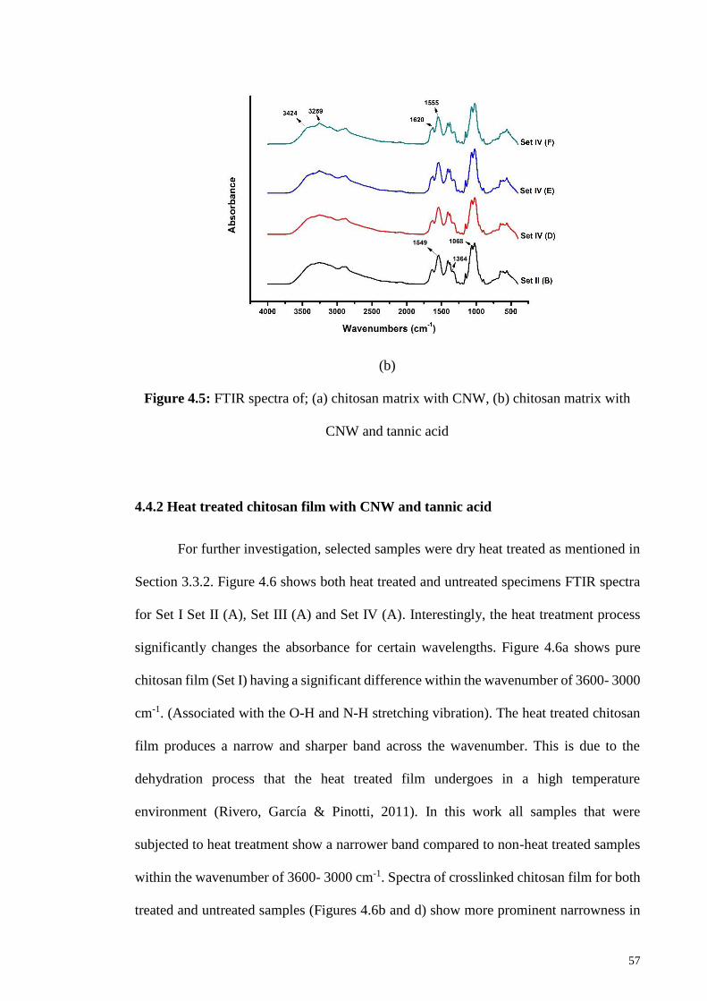
57
(b)
Figure 4.5: FTIR spectra of; (a) chitosan matrix with CNW, (b) chitosan matrix with
CNW and tannic acid
4.4.2 Heat treated chitosan film with CNW and tannic acid
For further investigation, selected samples were dry heat treated as mentioned in
Section 3.3.2. Figure 4.6 shows both heat treated and untreated specimens FTIR spectra
for Set I Set II (A), Set III (A) and Set IV (A). Interestingly, the heat treatment process
significantly changes the absorbance for certain wavelengths. Figure 4.6a shows pure
chitosan film (Set I) having a significant difference within the wavenumber of 3600- 3000
cm-1. (Associated with the O-H and N-H stretching vibration). The heat treated chitosan
film produces a narrow and sharper band across the wavenumber. This is due to the
dehydration process that the heat treated film undergoes in a high temperature
environment (Rivero, García & Pinotti, 2011). In this work all samples that were
subjected to heat treatment show a narrower band compared to non-heat treated samples
within the wavenumber of 3600- 3000 cm-1. Spectra of crosslinked chitosan film for both
treated and untreated samples (Figures 4.6b and d) show more prominent narrowness in
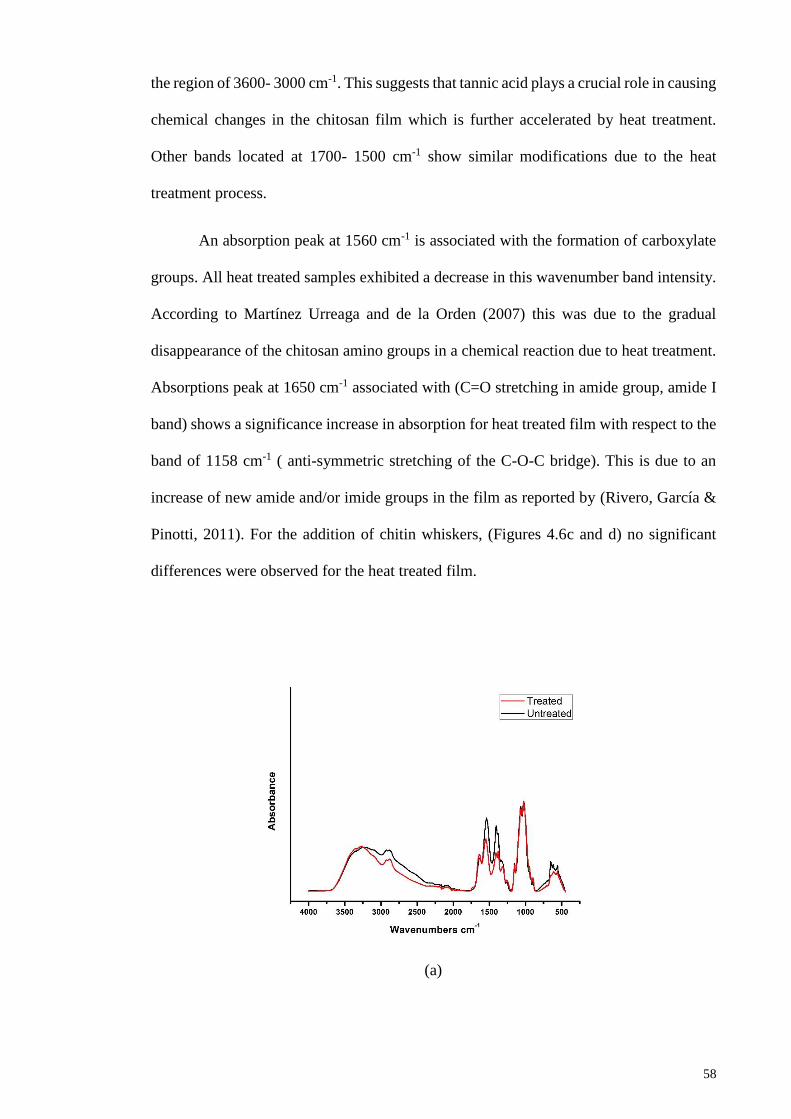
58
the region of 3600- 3000 cm-1. This suggests that tannic acid plays a crucial role in causing
chemical changes in the chitosan film which is further accelerated by heat treatment.
Other bands located at 1700- 1500 cm-1 show similar modifications due to the heat
treatment process.
An absorption peak at 1560 cm-1 is associated with the formation of carboxylate
groups. All heat treated samples exhibited a decrease in this wavenumber band intensity.
According to Martínez Urreaga and de la Orden (2007) this was due to the gradual
disappearance of the chitosan amino groups in a chemical reaction due to heat treatment.
Absorptions peak at 1650 cm-1 associated with (C=O stretching in amide group, amide I
band) shows a significance increase in absorption for heat treated film with respect to the
band of 1158 cm-1 ( anti-symmetric stretching of the C-O-C bridge). This is due to an
increase of new amide and/or imide groups in the film as reported by (Rivero, García &
Pinotti, 2011). For the addition of chitin whiskers, (Figures 4.6c and d) no significant
differences were observed for the heat treated film.
(a)
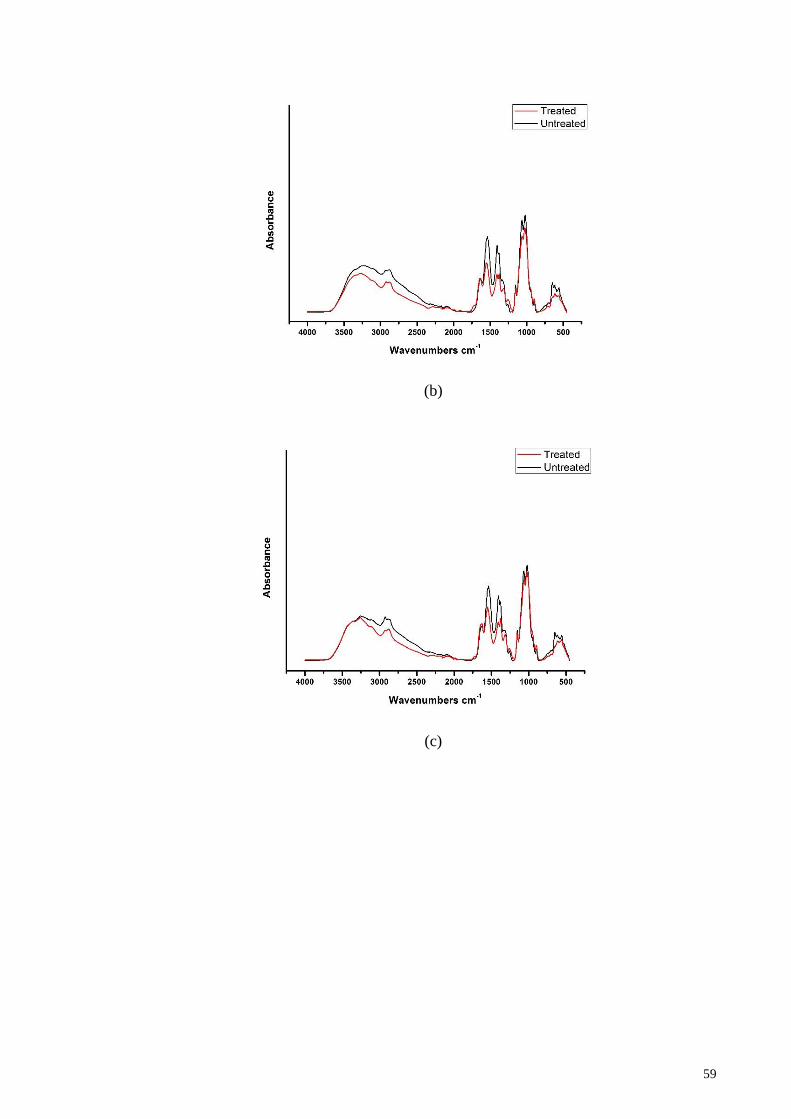
59
(b)
(c)
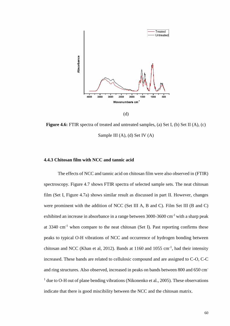
60
(d)
Figure 4.6: FTIR spectra of treated and untreated samples, (a) Set I, (b) Set II (A), (c)
Sample III (A), (d) Set IV (A)
4.4.3 Chitosan film with NCC and tannic acid
The effects of NCC and tannic acid on chitosan film were also observed in (FTIR)
spectroscopy. Figure 4.7 shows FTIR spectra of selected sample sets. The neat chitosan
film (Set I, Figure 4.7a) shows similar result as discussed in part II. However, changes
were prominent with the addition of NCC (Set III A, B and C). Film Set III (B and C)
exhibited an increase in absorbance in a range between 3000-3600 cm-1 with a sharp peak
at 3340 cm-1 when compare to the neat chitosan (Set I). Past reporting confirms these
peaks to typical O-H vibrations of NCC and occurrence of hydrogen bonding between
chitosan and NCC (Khan et al, 2012). Bands at 1160 and 1055 cm-1, had their intensity
increased. These bands are related to cellulosic compound and are assigned to C-O, C-C
and ring structures. Also observed, increased in peaks on bands between 800 and 650 cm-
1 due to O-H out of plane bending vibrations (Nikonenko et al., 2005). These observations
indicate that there is good miscibility between the NCC and the chitosan matrix.
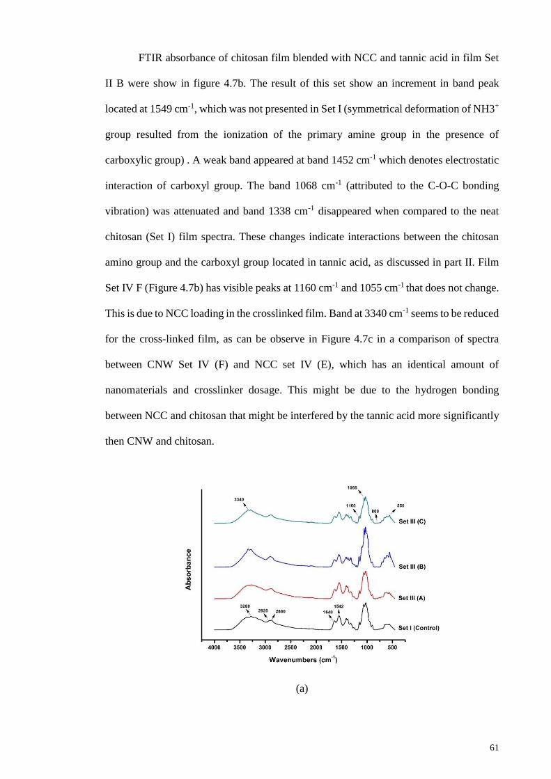
61
FTIR absorbance of chitosan film blended with NCC and tannic acid in film Set
II B were show in figure 4.7b. The result of this set show an increment in band peak
located at 1549 cm-1, which was not presented in Set I (symmetrical deformation of NH3+
group resulted from the ionization of the primary amine group in the presence of
carboxylic group) . A weak band appeared at band 1452 cm-1 which denotes electrostatic
interaction of carboxyl group. The band 1068 cm-1 (attributed to the C-O-C bonding
vibration) was attenuated and band 1338 cm-1 disappeared when compared to the neat
chitosan (Set I) film spectra. These changes indicate interactions between the chitosan
amino group and the carboxyl group located in tannic acid, as discussed in part II. Film
Set IV F (Figure 4.7b) has visible peaks at 1160 cm-1 and 1055 cm-1 that does not change.
This is due to NCC loading in the crosslinked film. Band at 3340 cm-1 seems to be reduced
for the cross-linked film, as can be observe in Figure 4.7c in a comparison of spectra
between CNW Set IV (F) and NCC set IV (E), which has an identical amount of
nanomaterials and crosslinker dosage. This might be due to the hydrogen bonding
between NCC and chitosan that might be interfered by the tannic acid more significantly
then CNW and chitosan.
(a)
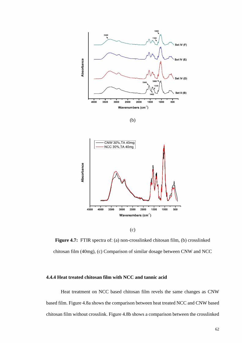
62
(b)
(c)
Figure 4.7: FTIR spectra of: (a) non-crosslinked chitosan film, (b) crosslinked
chitosan film (40mg), (c) Comparison of similar dosage between CNW and NCC
4.4.4 Heat treated chitosan film with NCC and tannic acid
Heat treatment on NCC based chitosan film revels the same changes as CNW
based film. Figure 4.8a shows the comparison between heat treated NCC and CNW based
chitosan film without crosslink. Figure 4.8b shows a comparison between the crosslinked

63
heat treated films. Major difference were seen in the spectra of 3000-3600 cm-1. Not much
dehydration occurs on NCC based chitosan film during heat treatment, when compared
to CNW based chitosan film. This is due to the lower moisture content presented in NCC
based film (as discussed in physicochemical section in this research). The wavenumber
at 1549 cm-1 indicates C-N and N-H stretching vibrations for both NCC and CNW. These
results are in agreement with past research done (Sionkowska et al., 2014; Pradal et al.,
2011). Heat treatment decreases the absorbance of all the sample film in this region,
suggesting some bonds were broken due to the heat treatment process.
(a)

64
(b)
Figure 4.8: Comparison between CNW and NCC heat treated chitosan film: (a)
without crosslinker, (b) with crosslinker
4.5 Chemical interaction studies by XRD analysis
4.5.1 Chitosan film with CNW and tannic acid
An X-ray diffraction study was conducted to investigate the microstructure and
crystalline structure. Figure 4.9 shows X-ray diffractograms for CNW based chitosan film
of four samples, one from each of the four sets. The four samples shown were selected
because each had the highest concentration of additives within their particular set. These
include: Set I (control), Set II (B) 100% chitosan with 40 mg of tannic acid, Set III (C)
30% of chitin whiskers, Set IV (F) 30% of chitin whiskers with 40 mg of tannic acid and
pure chitin whiskers. Neat chitosan film exhibited 2 major peaks located at 2θ=22.6° and
11.4° and two other minor peaks located at 18.1° and 9.3°. These two major peaks are
associated with the hydrated “tendons” conformation of chitosan as reported by (Ogawa,

65
Yui & Okuyama, 2004). According to Rivero, García and Pinotti (2010) addition of tannic
acid (Set II (B)) raises the peak in the region at 2θ=15° (insert in Figure 10) that exhibits
the characteristic of anhydrous (“annealed”) crystalline conformation. In present work,
all films in Sets II and IV exhibited similar behavior at 2θ=15°.
Sets III and IV both have a significant rise in the peak than Set I due to the
introduction of chitin whiskers. Sets III (C) and Set IV (F) exhibits two major peaks
located at 2θ=19.3° and 9.3° and minor peaks at 23.5° and 21.1°. According to Kadokawa
et al. (2011) this is a typical diffraction pattern observed with chitin powder. It indicates
that the crystallinity of α-chitin powder is the same as the embedded chitin whiskers.
Addition of chitin whiskers showed strong scattering peak of chitin whiskers being more
significant with increasing whisker content. However, with the addition of whisker
content, the relative intensity and width of scattering peaks belonging to Set I did not
change. This indicates that the addition of chitin whiskers does not affect the apparent
degree of crystallinity of the chitosan matrix. As similar trend reported by Sriupayo et al.
(2005) where the increasing α-chitin whisker doesn’t change the intensity and the width
of the scattering peaks of the chitosan matrix and indicated that the presence of α-chitin
whisker did not affect the crystallinity of the matrix.
Figure 4.9: XRD diffractograms of selected CNW based chitosan film

66
4.5.2 Heat treated chitosan film with CNW and tannic acid
Heat treated X-ray diffractograms of selected CNW based chitosan film were
shown in Figure 4.10. Neat chitosan film (Set I), both with and without heat treatment, is
shown in Figure 4.10a. These results show some changes in the peaks. Non treated film
exhibits two major peaks at 2θ= 22.6° and 11.4° and two minor peaks located at 2θ=18.1°
and 9.3°. These results were same as previous batch. Heat treatment of the chitosan film
diminishes the peak at 11.4° and shifts another peak to higher 2θ values in the region of
18° to 24°.These results agree with those published by (Ritthidej, Phaechamud &
Koizumi, 2002). Heat treatment of chitosan film changes the structure to anhydrous
conformation of chitosan similar to crosslinked samples as in Figure 4.10b. All heat
treated samples experience disappearance of the peak around 2θ= 11.4°. Crosslinked
chitosan film (Figure 4.10b) shows a peak at 2θ=15° which is associated with the
characteristic of anhydrous crystalline conformation. Heat treated samples of crosslinked
chitosan film shows flattening effects at 2θ=15°. Similar results were obtained by (Toffey
& Glasser 1999). This indicates a synergic effect of tannic acid and heating of the chitosan
film.
Figure 4.10c and d show a significant peak rise due to the addition of chitin
whiskers. As discussed earlier two major peaks are located at 2θ=19.3° and 9.3° and two
minor peaks are located at 23.5° and 21.1° (associated with α-chitin). Heat treatment of
this film gives a slight reduction on peak intensity at 23.5°. The change of this peak
reflects a change in the mechanical properties of the heat treated films.

67
(a)
(b)
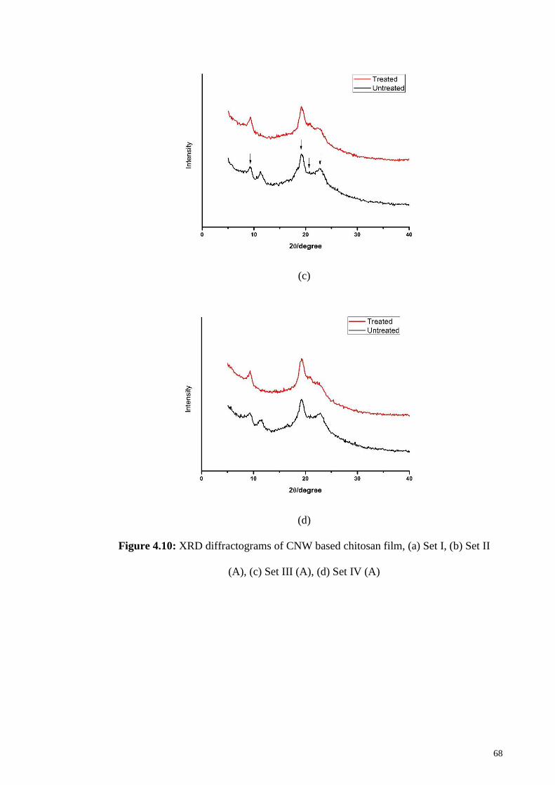
68
(c)
(d)
Figure 4.10: XRD diffractograms of CNW based chitosan film, (a) Set I, (b) Set II
(A), (c) Set III (A), (d) Set IV (A)
69
4.5.3 Chitosan film with NCC and tannic acid
The structural analysis by the X-ray diffraction method for NCC based chitosan
film were shown in Figure 4.11. Only four samples shown were selected because each
had the highest concentration of additives within their particular set. These includes: Set
I (control), Set II (B) 100% chitosan with 40 mg of tannic acid, Set III (C) 50% of NCC,
and Set IV (F) 50% of NCC with 40 mg of tannic acid. Neat chitosan exhibited a sharp
peak at 2θ=11.4° and broader peak at 2θ=22.6° and two other minor peaks located at
18.1° and 9.3° which are identical with previous batch. Sample Set II (B) shows peaks in
the region at 2θ=15°, and 21°, which was not available for sample Set I. The addition of
tannic acid raises the peak that exhibits the characteristic of anhydrous (“annealed”)
crystalline conformation.
Sample Sets III and IV have a significant rise in the peak compared to Set I, due
to the introduction of NCC. Sets III (C) and Set IV (F) exhibits highest scattering intensity
located at 2θ=22.4°, 16.5° and 14.5°, which correspond to the (11 ̅0), (1 1 0), and (2 0 0)
planes of the cellulose I crystal type as according to (Ma et al.,2011). This shows that
NCC has higher degree of crystallinity. The addition of NCC resulted in a strong
scattering peak of cellulose signature, which becomes more significant with increasing
filler content. Characteristics of the amorphous chitosan in the range of 2θ=20-23°, were
super-positioned with the peaks of NCC. The increase in peak intensity of the pure
chitosan film may due to transcrystallization effect. This effects can be define as
orientation of crystals in a semicrystalline matrix perpendicularly to the cellulose
nanocrystals (Helbert & Chanzy, 1994). Another research conducted by Gray (2008)
reported that crystallization of a polymer matrix were nucleated by cellulose nanocrystals
leading to a transcrystalline layer around the cellulose nanocrystals. This shows that the
films in Set III and IV exhibited a combination of amorphous and crystalline regions.

70
Figure 4.11: Comparison of X-ray diffractograms of chosen sample sets
4.5.4 Heat treated chitosan film with NCC and tannic acid
For the heat treated NCC samples, Figure 4.12 shows the XRD diffractograms of
both treated and untreated samples of Set III (A) and Set IV (A). Both the treated and
untreated film show some significant changes in scattering intensity. All heat treated
samples were observed to exhibit a flattening of peak around 11.4° for all samples as
observed before on the heat treated CNW based chitosan film. This shows that the heat
treatment has an effect on the molecular structure of chitosan. Furthermore heat treated
samples show an increased intensity in the region of 2θ = 19° to 22°. Previous published
result postulate that heat treatment does not increase the crystallinity of the film and there
is a possibility of lower crystallinity due to intense crosslinking interaction during heat
treatment that would inhibit the formation of the crystalline structure (Thakhiew et al.,
2015).

71
(a)
(b)
Figure 4.12: XRD diffractograms of : (a) Set III (A) and (b) Set IV (A)

72
4.6 Performance testing by UTM test
In this section all CNW, Heat treated CNW, NCC and heat treated NCC films
were tested and analyzed. Figure 4.13 shows the average mechanical properties of sample
Set I and II from 4 separate batches. The control film (Set I) exhibits a low tensile strength
of 30.8 MPa, with a maximum elongation of break of 45.6% (Figure 4.13a and b). The
addition of tannic acid as a crosslinking agent increases the tensile strength. Set II (A)
recorded a tensile strength of 40.9 MPa with an elongation at break of 37.1%. However,
the further addition of tannic acid, as done in Set II (B), yielded a slight increase in tensile
strength (43.5 MPa). For Young’s Modulus (Figure 4.13c), chitosan film recorded the
lowest stiffness of 664.8 MPa. Crosslinked chitosan film shows an increment in the
stiffness of the film significantly up to 901.4 MPa and 1291.0 MPa for 20 mg and 40 mg
of tannic acid addition.
The addition of tannic acid clearly increases the tensile strength and Young’s
modulus, but decreases the elongation at break. The increment of tensile strength could
be link to the formation of a more stable polymer network due to attractive interactions
between chitosan and tannic acid. The compaction of polymer network leads to increase
in stiffness and reduction in elongation at break. However the tensile difference between
20 mg and 40 mg was just 2.5 MPa, this might be due to excess crosslinking the limits
the mobility of the chitosan molecule, leading to lower tensile strength. A similar behavior
was observed in past research involving gelatin based film (de Carvalho & Grosso, 2004)
and ester crosslinking of cotton fabric by polymeric carboxylic acids and citric acid
(Yang, Wang & Kang, 1997).
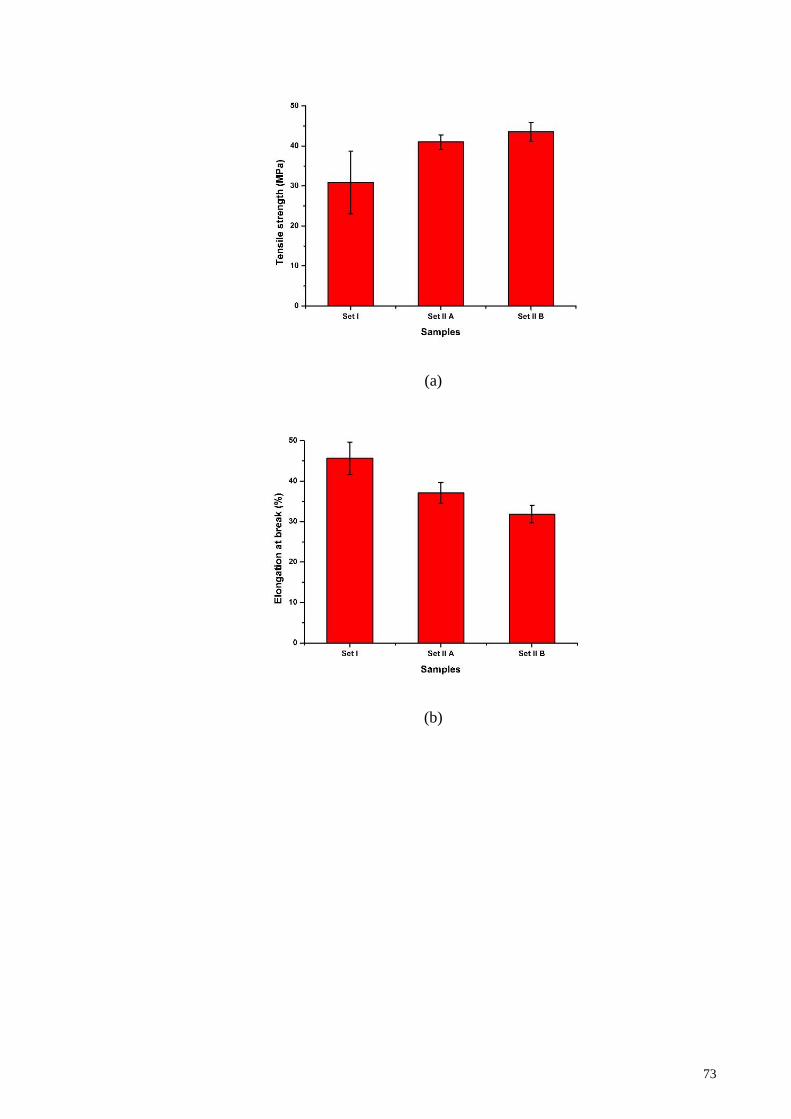
73
(a)
(b)
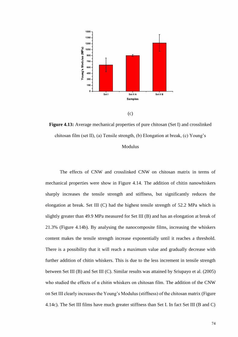
74
(c)
Figure 4.13: Average mechanical properties of pure chitosan (Set I) and crosslinked
chitosan film (set II), (a) Tensile strength, (b) Elongation at break, (c) Young’s
Modulus
The effects of CNW and crosslinked CNW on chitosan matrix in terms of
mechanical properties were show in Figure 4.14. The addition of chitin nanowhiskers
sharply increases the tensile strength and stiffness, but significantly reduces the
elongation at break. Set III (C) had the highest tensile strength of 52.2 MPa which is
slightly greater than 49.9 MPa measured for Set III (B) and has an elongation at break of
21.3% (Figure 4.14b). By analysing the nanocomposite films, increasing the whiskers
content makes the tensile strength increase exponentially until it reaches a threshold.
There is a possibility that it will reach a maximum value and gradually decrease with
further addition of chitin whiskers. This is due to the less increment in tensile strength
between Set III (B) and Set III (C). Similar results was attained by Sriupayo et al. (2005)
who studied the effects of α chitin whiskers on chitosan film. The addition of the CNW
on Set III clearly increases the Young’s Modulus (stiffness) of the chitosan matrix (Figure
4.14c). The Set III films have much greater stiffness than Set I. In fact Set III (B and C)
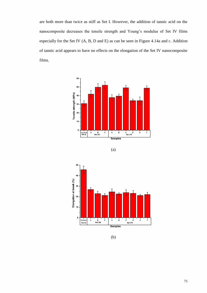
75
are both more than twice as stiff as Set I. However, the addition of tannic acid on the
nanocomposite decreases the tensile strength and Young’s modulus of Set IV films
especially for the Set IV (A, B, D and E) as can be seen in Figure 4.14a and c. Addition
of tannic acid appears to have no effects on the elongation of the Set IV nanocomposite
films.
(a)
(b)
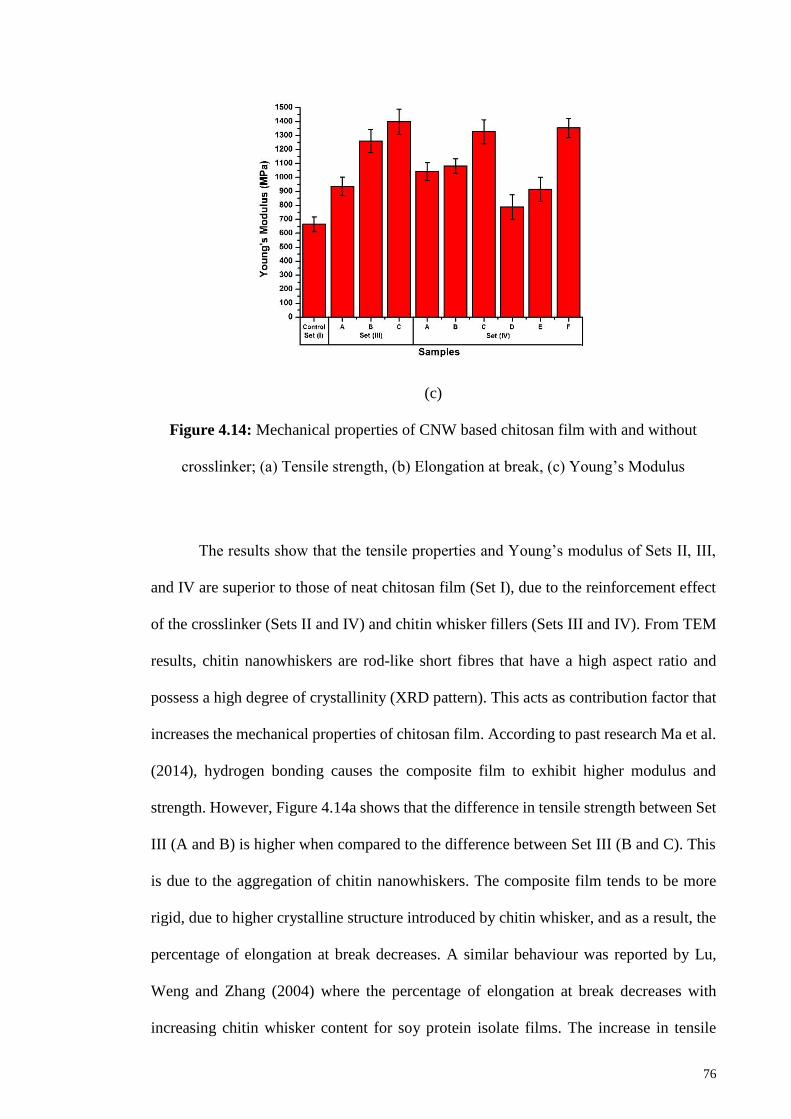
76
(c)
Figure 4.14: Mechanical properties of CNW based chitosan film with and without
crosslinker; (a) Tensile strength, (b) Elongation at break, (c) Young’s Modulus
The results show that the tensile properties and Young’s modulus of Sets II, III,
and IV are superior to those of neat chitosan film (Set I), due to the reinforcement effect
of the crosslinker (Sets II and IV) and chitin whisker fillers (Sets III and IV). From TEM
results, chitin nanowhiskers are rod-like short fibres that have a high aspect ratio and
possess a high degree of crystallinity (XRD pattern). This acts as contribution factor that
increases the mechanical properties of chitosan film. According to past research Ma et al.
(2014), hydrogen bonding causes the composite film to exhibit higher modulus and
strength. However, Figure 4.14a shows that the difference in tensile strength between Set
III (A and B) is higher when compared to the difference between Set III (B and C). This
is due to the aggregation of chitin nanowhiskers. The composite film tends to be more
rigid, due to higher crystalline structure introduced by chitin whisker, and as a result, the
percentage of elongation at break decreases. A similar behaviour was reported by Lu,
Weng and Zhang (2004) where the percentage of elongation at break decreases with
increasing chitin whisker content for soy protein isolate films. The increase in tensile

77
strength and Young’s modulus by crosslinking is probably due to the formation of a more
stable network between chitosan and tannic acid. Figure 4.13a shows that a further
increase of tannic acid results in an insignificant increase in tensile strength for Set II
films. This suggests that a slight phase separation occurs, which will reduce the tensile
strength as further increments of tannic acid is added. A similar trend was reported by
Peña et al. (2010), reported that a slight phase separation reduced the tensile strength as
more tannic acid was added into the gelatin film. The transparency of the film also
deteriorated with a higher loading of tannic acid, which agrees well that a slight phase
separation took place. The transparency of our film also reduced with the higher loading
of tannic acid in Set II (B) and Set IV (D, E and F). Introduction of tannic acid to the Set
IV films resulted in a marked decrease in tensile strength and Young’s modulus. This is
likely due to crosslinking effect of the tannic acid that jeopardises the formation of the
chitin network in the chitosan matrix. This phenomenon was explained by past research
Gopalan Nair and Dufresne (2003a) found that strength of the chitin network in the
crosslinked natural rubber matrix is lower than that in unvulcanized rubber. They
concluded that the chemical crosslinking of the matrix most probably interferes with the
formation of the chitin network, thereby a lower tensile modulus in vulcanized samples
compared to unvulcanized samples.
The addition of NCC based chitosan film with and without crosslinker yields
further improvement in mechanical properties (Figure 4.15). The measured mechanical
properties of Set I, III and IV shown in Figure 4.15. With the addition of NCC, the tensile
strength increased significantly (Figure 4.15a) for Set III B and C and the elongation at
break were drastically reduced. Set III (C) records the highest tensile strength of 57.2
MPa for a non crosslinked film, with an elongation-at-break of 15.4%. Set IV (D) had the
highest tensile strength which is 61.5 MPa. This is a 99.15% increase when compared to
neat chitosan and has an elongation-at-break of 14.0%. The addition of tannic acid

78
appears to have no effect on the elongation of Set IV nanocomposite films. The addition
of the NCC and tannic acid (Set III and IV) increases the Young’s Modulus (stiffness) of
the chitosan matrix (Figure 5.15c). The Set IV films have much greater stiffness than Set
I. In fact, films in Set III (C), Set IV (C, D, E and F) are more than twice as stiff as Set I.
Figure 4.15d shows the comparison of tensile strength between CNW and NCC based
chitosan film. NCC based film is superior to the CNW based film in higher loading
content of 30%. Also observed that, the addition of 10 % NCC into the crosslinked film
shows an improvement but yields a deteriorating strength for CNW based film. For higher
loading of nanomaterials, both NCC and CNW based films shows a downtrend in tensile
strength. Among all the samples, a formulation of 10% NCC and 40 mg TA possess the
highest tensile strength of 61.49 MPa.
(a)
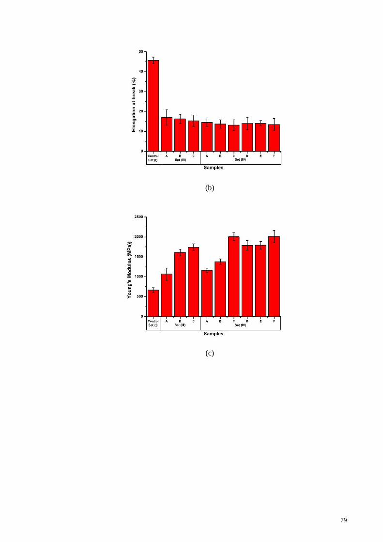
79
(b)
(c)

80
(d)
Figure 4.15: Mechanical properties of NCC based chitosan film with and without
crosslinker; (a) Tensile strength, (b) Elongation at break, (c) Young’s Modulus, (d)
Comparison of tensile strength between CNW and NCC based chitosan film
These results shows that the composite films have superior tensile strength and
Young’s modulus compared to neat chitosan film (Set I), due to the reinforcement effect
of the crosslinker and NCC. The increase in tensile strength caused by the addition of
NCC in the chitosan film that can be attributed due to the reinforcing effect through
effective stress transfer from the nanocrystals and chitosan polymer interface. Another
group of researcher de Mesquita, Donnici and Pereira (2010) postulates that the
interaction between anionic sulfate groups of NCC and the cationic amine groups of the
chitosan promotes good bonding between them and this may lead to higher tensile
strength. The TEM images and XRD diffractograms shows that the NCC were rod-like
shape that have a high aspect ratio and possess a high degree of crystallinity. This proves
to be another contribution factor that increases the mechanical properties. However,
tensile increment difference between films in Set III (A, B) and (B, C) is huge. This shows
that increasing the nanocrystals content makes the tensile strength exponentially increase
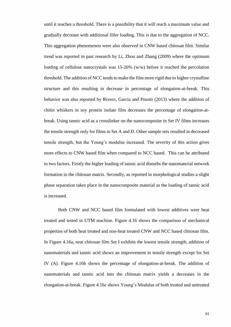
81
until it reaches a threshold. There is a possibility that it will reach a maximum value and
gradually decrease with additional filler loading. This is due to the aggregation of NCC.
This aggregation phenomenon were also observed in CNW based chitosan film. Similar
trend was reported in past research by Li, Zhou and Zhang (2009) where the optimum
loading of cellulose nanocrystals was 15-20% (w/w) before it reached the percolation
threshold. The addition of NCC tends to make the film more rigid due to higher crystalline
structure and this resulting in decrease in percentage of elongation-at-break. This
behavior was also reported by Rivero, Garcia and Pinotti (2013) where the addition of
chitin whiskers in soy protein isolate film decreases the percentage of elongation-at-
break. Using tannic acid as a crosslinker on the nanocomposite in Set IV films increases
the tensile strength only for films in Set A and D. Other sample sets resulted in decreased
tensile strength, but the Young’s modulus increased. The severity of this action gives
more effects to CNW based film when compared to NCC based. This can be attributed
to two factors. Firstly the higher loading of tannic acid disturbs the nanomaterial network
formation in the chitosan matrix. Secondly, as reported in morphological studies a slight
phase separation takes place in the nanocomposite material as the loading of tannic acid
is increased.
Both CNW and NCC based film formulated with lowest additives were heat
treated and tested in UTM machine. Figure 4.16 shows the comparison of mechanical
properties of both heat treated and non-heat treated CNW and NCC based chitosan film.
In Figure 4.16a, neat chitosan film Set I exhibits the lowest tensile strength, addition of
nanomaterials and tannic acid shows an improvement in tensile strength except for Set
IV (A). Figure 4.16b shows the percentage of elongation-at-break. The addition of
nanomaterials and tannic acid into the chitosan matrix yields a decreases in the
elongation-at-break. Figure 4.16c shows Young’s Modulus of both treated and untreated
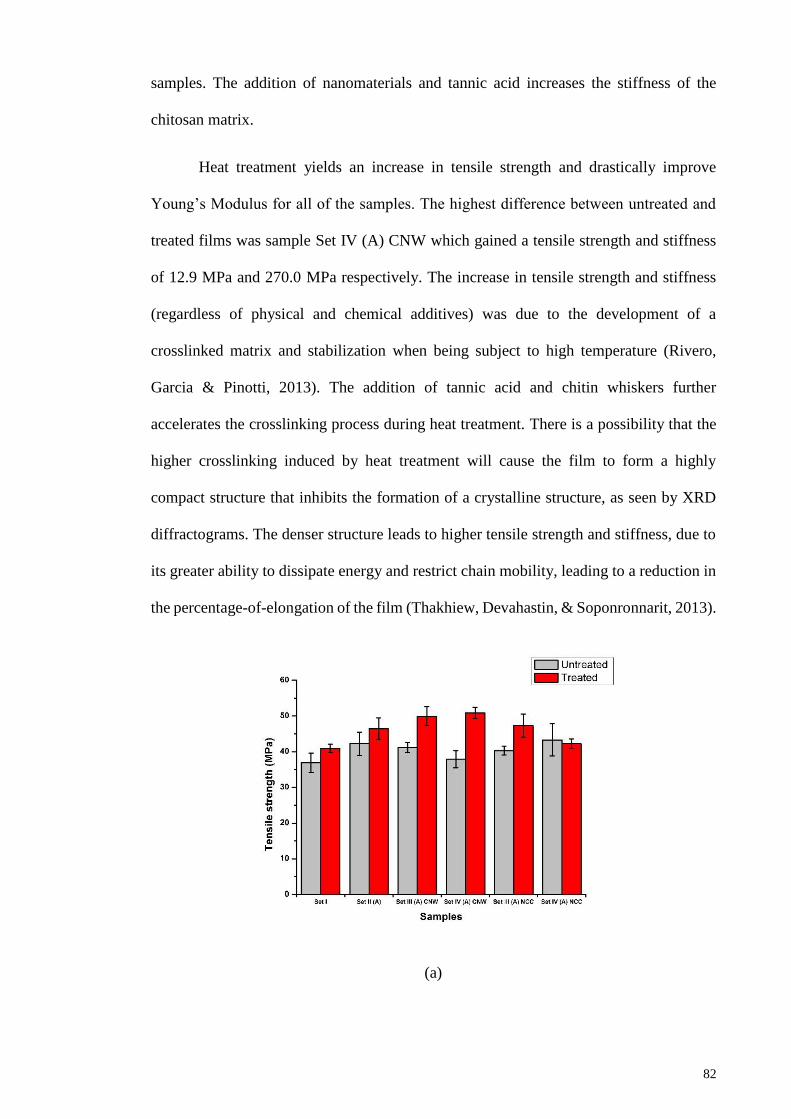
82
samples. The addition of nanomaterials and tannic acid increases the stiffness of the
chitosan matrix.
Heat treatment yields an increase in tensile strength and drastically improve
Young’s Modulus for all of the samples. The highest difference between untreated and
treated films was sample Set IV (A) CNW which gained a tensile strength and stiffness
of 12.9 MPa and 270.0 MPa respectively. The increase in tensile strength and stiffness
(regardless of physical and chemical additives) was due to the development of a
crosslinked matrix and stabilization when being subject to high temperature (Rivero,
Garcia & Pinotti, 2013). The addition of tannic acid and chitin whiskers further
accelerates the crosslinking process during heat treatment. There is a possibility that the
higher crosslinking induced by heat treatment will cause the film to form a highly
compact structure that inhibits the formation of a crystalline structure, as seen by XRD
diffractograms. The denser structure leads to higher tensile strength and stiffness, due to
its greater ability to dissipate energy and restrict chain mobility, leading to a reduction in
the percentage-of-elongation of the film (Thakhiew, Devahastin, & Soponronnarit, 2013).
(a)

83
(b)
(c)
Figure 4.16: Comparison of both heat treated and non-treated nanocomposite film;
(a) Tensile strength, (b) Elogation at break, (c) Young’s Modulus
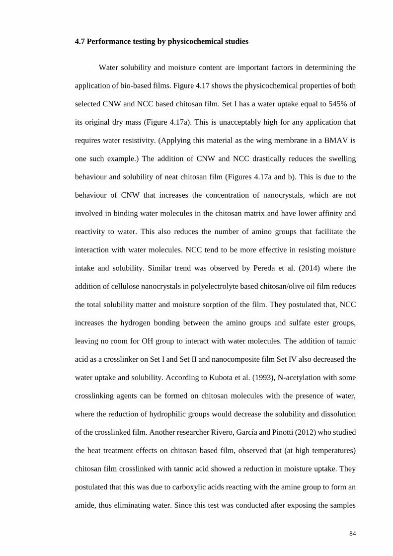
84
4.7 Performance testing by physicochemical studies
Water solubility and moisture content are important factors in determining the
application of bio-based films. Figure 4.17 shows the physicochemical properties of both
selected CNW and NCC based chitosan film. Set I has a water uptake equal to 545% of
its original dry mass (Figure 4.17a). This is unacceptably high for any application that
requires water resistivity. (Applying this material as the wing membrane in a BMAV is
one such example.) The addition of CNW and NCC drastically reduces the swelling
behaviour and solubility of neat chitosan film (Figures 4.17a and b). This is due to the
behaviour of CNW that increases the concentration of nanocrystals, which are not
involved in binding water molecules in the chitosan matrix and have lower affinity and
reactivity to water. This also reduces the number of amino groups that facilitate the
interaction with water molecules. NCC tend to be more effective in resisting moisture
intake and solubility. Similar trend was observed by Pereda et al. (2014) where the
addition of cellulose nanocrystals in polyelectrolyte based chitosan/olive oil film reduces
the total solubility matter and moisture sorption of the film. They postulated that, NCC
increases the hydrogen bonding between the amino groups and sulfate ester groups,
leaving no room for OH group to interact with water molecules. The addition of tannic
acid as a crosslinker on Set I and Set II and nanocomposite film Set IV also decreased the
water uptake and solubility. According to Kubota et al. (1993), N-acetylation with some
crosslinking agents can be formed on chitosan molecules with the presence of water,
where the reduction of hydrophilic groups would decrease the solubility and dissolution
of the crosslinked film. Another researcher Rivero, García and Pinotti (2012) who studied
the heat treatment effects on chitosan based film, observed that (at high temperatures)
chitosan film crosslinked with tannic acid showed a reduction in moisture uptake. They
postulated that this was due to carboxylic acids reacting with the amine group to form an
amide, thus eliminating water. Since this test was conducted after exposing the samples
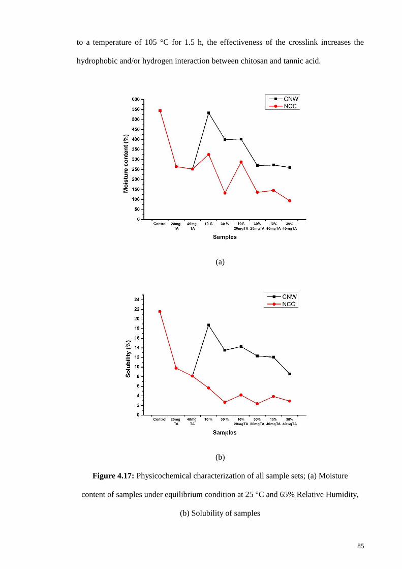
85
to a temperature of 105 °C for 1.5 h, the effectiveness of the crosslink increases the
hydrophobic and/or hydrogen interaction between chitosan and tannic acid.
(a)
(b)
Figure 4.17: Physicochemical characterization of all sample sets; (a) Moisture
content of samples under equilibrium condition at 25 °C and 65% Relative Humidity,
(b) Solubility of samples

86
The effects of heat treatment on moisture uptake for both CNW and NCC based
chitosan film is shown in Figure 4.18. It have been discussed that the addition of CNW,
NCC and tannic acid is known to improve the water resistivity. Heat treatment further
reduce the moisture uptake capability of the chitosan film. Water resistivity was
significantly enhanced by heat treatment. For Set I, a reduction from 545% to 182% of
moisture by weight was recorded for the heat treated sample. This same behavior was
recorded for all the other heat treated samples. Similar results were obtained by several
researchers (Ghosh, Ali & Dias, 2009; Kim et al., 2002). Heat treatment increases the
crosslinking process that led to compaction of film structure. This compaction creates a
difficult path for water molecules to pass through (Li et al., 2015). Other research stressed
that these changes are due to fact that the chitosan matrix had an increase in its degree of
acetylation at elevated temperatures. These changes are due to the release of water from
the matrix at higher temperatures (150 °C – 200 °C) Kim et al. (2002). The chemical
changes at elevated temperatures converts chitosan into a chitin-like material.
(a)

87
(b)
Figure 4.18: Moisture content of both treated and untreated samples ; (a) CNW based
chitosan film, (b) NCC based chitosan film
4.8 Performance testing by water contact angle (Wettability)
Contact angle is another important parameter that can define a materials
hydrophobic/hydrophilic properties. It is the measurement of tangent line at the point of
contact of the liquid droplets. Selected films were preconditioned in desiccator were
tested for a wettability using distilled water. Figure 4.19 shows static water contact angle
for film Set I, Set II (A), Set III (A) and Set IV (A) and the heat treated part. The main
reason for this selection is to examine the effects on the wettability having a minimum
amount of nanomaterial and crosslinker. Pure chitosan film Set I exhibit contact angle
value of 90° which is in the range comparable value produced by (Croisier & Jérôme,
2013). Although chitosan is hydrophilic by nature, its wettability could be affected when
blending with another material or by heat treatment. Addition of tannic acid as a
crosslinker yields an insignificant value of 92°. However introduction of nanomaterials
translate the chitosan film to exhibit hydrophobic properties. Films in Set III (A) shows a

88
contact angle of 99.8° (CNW based) and 100.3° (NCC based). This is due to the
hydrophobic nature of nanomaterials that prevents the water molecules to slip into
hydrophilic surface of chitosan matrix. Crosslinked nanocomposite chitosan film Set IV
(A) exhibits a lower contact angle of 95.9° (CNW based) and 96.0° (NCC based).
Although these films shows better water absorption resistivity, it does not prove to be
useful in wettability. This is due to the nature of films in Set IV that have a smoother
surface when compared to films in Set III as examined in SEM. Rough and porous films
usually display a highly hydrophobic character due to the surface roughness and
possibilities of air entrapped inside the pores. Similar result was attained by (Teng et al.
(2015) who conducted a study to investigate conductive polymer porous film with tunable
wettability and adhesion. Heat treatment counterpart shows a slight improvement on the
wettability except for Set III which shows some reduction on contact angle. This suggest
that hydrophilic nature of chitosan film can be altered with physical and chemical
additives.
(a) (g)

89
(b) (h)
(c) (i)
(d) (j)
(e) (k)

90
(f) (l)
Figure 4.19: Water contact angle of 2 μL of dispersion for; (a) Set I, (b) Set II (A),
(c) Set III (A-CNW), (d) Set IV (A-CNW), (e) Set III (A-NCC), (f) Set IV (A-NCC),
(g-l) Heat treated counterpart
It is important for a BMAV to have a hydrophobic surface on the film membrane
to sustain flight in humid environments. The water contact angle for actual dragonfly
wing membrane is 143° (Figure 4.20). This super hydrophobic properties is due to the
design of the dragonfly wing surface that have air pockets by the groove of the dorsal and
ventral layers. Besides, the membrane is covered with super hydrophobic wax and the
membrane has a beads like surface which helps to increase its wettability (Sun &
Bhushan, 2012). A study have been conducted by Song et al. (2007) reported actual
dragonfly wing have a contact angle of 177°, which very closely approached the
theoretical limit of a water contact angle of 180°. Such the super hydrophobicity makes
the dragonfly effective in flying in the rain and keep its wings non-wetting and self-
cleaning. This properties is also reported to reduce drag during flight.
91
Figure 4.20: Water contact angle of actual dragonfly wing
4.9 Performance testing by optical transmittance (UV-visible spectrophotometer)
NCC based chitosan film were tested for optical performance to investigate the
reason for mechanical properties fluctuation since there is a chance for phase separation
and aggregation to occur with high loading content of NCC and tannic acid, as discussed
in Section 4.6. The visible light transparency for all NCC based sample sets is shown in
Figure 4.21. The printed letter “Sample” can be seen for all sample sets clearly since all
the samples were translucent. Generally all sample sets exhibit a slight yellow
appearance. The addition of tannic acid tends to make the film appear more yellowish,
due to oxidative reactions as discussed by (Rivero, García & Pinotti, 2010). The word
“Sample” becomes more blurred with increasing NNC loading especially for sample Set
III (C) due to increasing surface roughness.
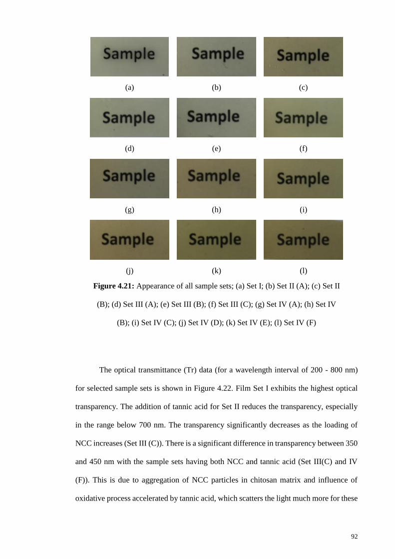
92
(a) (b) (c)
(d) (e) (f)
(g) (h) (i)
(j) (k) (l)
Figure 4.21: Appearance of all sample sets; (a) Set I; (b) Set II (A); (c) Set II
(B); (d) Set III (A); (e) Set III (B); (f) Set III (C); (g) Set IV (A); (h) Set IV
(B); (i) Set IV (C); (j) Set IV (D); (k) Set IV (E); (l) Set IV (F)
The optical transmittance (Tr) data (for a wavelength interval of 200 - 800 nm)
for selected sample sets is shown in Figure 4.22. Film Set I exhibits the highest optical
transparency. The addition of tannic acid for Set II reduces the transparency, especially
in the range below 700 nm. The transparency significantly decreases as the loading of
NCC increases (Set III (C)). There is a significant difference in transparency between 350
and 450 nm with the sample sets having both NCC and tannic acid (Set III(C) and IV
(F)). This is due to aggregation of NCC particles in chitosan matrix and influence of
oxidative process accelerated by tannic acid, which scatters the light much more for these

93
films than the control set (Set I) and Set II. This results further concludes the deteriorating
mechanical properties for higher loading of nanomaterials and tannic acid.
Figure 4.22: UV-visible spectrophotometer of chosen sample sets
4.10 Performance testing by nanoindentation test
Nanocomposite chitosan films that have been produced were then infused in
simplified dragonfly wing. NCC based sample Set IV (D) were chosen due to its
superiority in mechanical properties compared to other sample sets. Furthermore NCC
sample Set IV (D) closely matches the real dragonfly wing Young’s modulus of 1.5 to
2.9 GPa (Song et al., 2007; Kempf, 2000). Due to dragonfly wings small size and complex
vein design, it is impossible to analyses the mechanical properties from tensile testing. A
nanoindentation test is an alternative way to resolve this issue. The development of the
nanoindentation technique allows highly localized hardness and modulus measurements
to be performed on a very small material volume. Figure 4.23 shows the points of test
being conducted for the actual dragonfly wings and simplified BMAV wing. Specific

94
points were carefully selected based on their importance. Essentially, point 1; costa, point
2; wing tip, point 3: Nodus, point 4; Postal vein and point 5; Rudius were chosen due to
its significant role in retaining flight performance and strength. Approximately the same
points on the simplified dragonfly wings were indented for comparison.
(a)
(b)
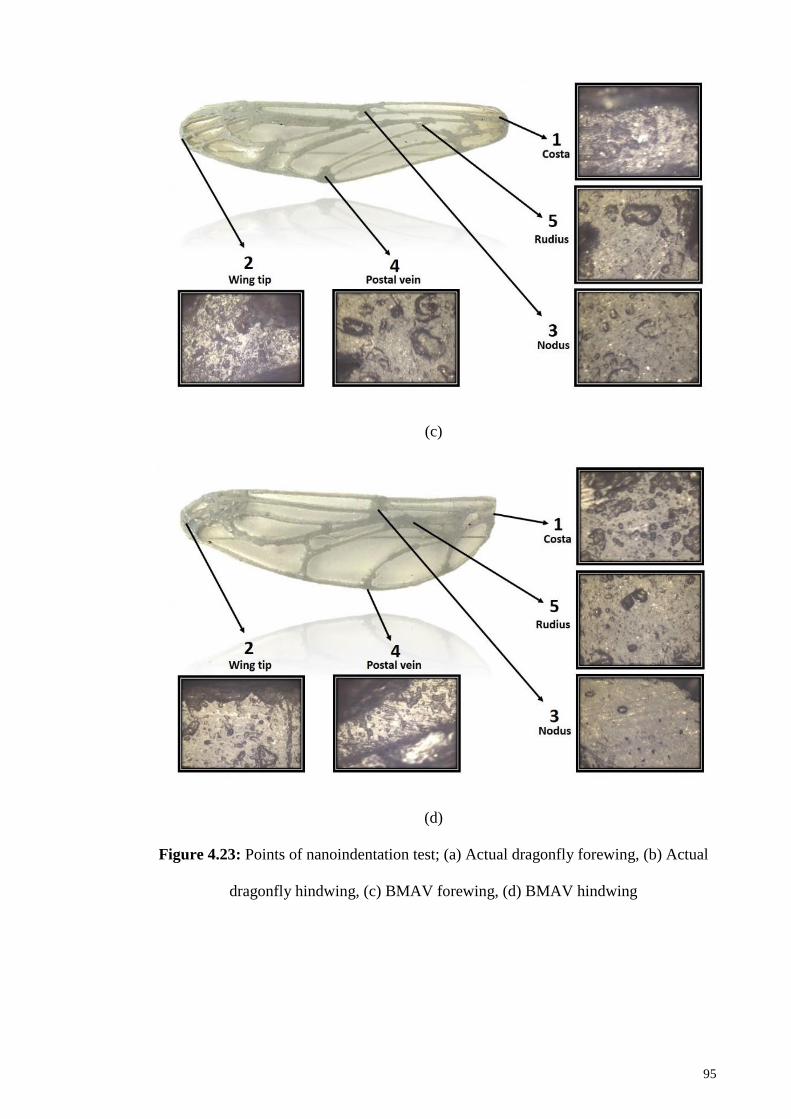
95
(c)
(d)
Figure 4.23: Points of nanoindentation test; (a) Actual dragonfly forewing, (b) Actual
dragonfly hindwing, (c) BMAV forewing, (d) BMAV hindwing

96
Table 4.1 shows the modulus and hardness of dragonfly forewing and simplified
PLA forewing. Table 4.2 shows the modulus and hardness of dragonfly hind wing and
simplified PLA hind wing. Different points on the wing bear different loads on actual
dragonfly wings, therefore their mechanical properties were different because of
adaptation. Relatively speaking, the mechanical properties of a real dragonfly wing vary
with the position. Group of researchers Sun et al. (2010) examined the mechanical
properties of the costa, rudius and postal veins (Refer to Figure 4.23 for the points) of a
dragonfly wing and concluded that variation in modulus were in between 0.5 GPa to 3.5
Gpa. The modulus and hardness we retrieved from different points were comparable to
previously published article by (Kesel, Philippi & Nachtigall 1998; Song et al., 2007; C.
H. Chang et al., 2009). Costa, Nodus and Rudius (fore wing) and Rudius (hind wing)
displayed a very high modulus compared to other points. Almost all points (except point
5 on the hind wing) have a uniform modulus. As suspected, the modulus of both fore
wing and hind wing of simplified BMAV wings were highest in the dense 3D printed
section. Point 4 in the BMAV hind wing has the lowest modulus and hardness. This is
due to a very narrow and small quantity of jagged PLA “vein” structure in point 5 that
yields a modulus of 0.9 GPa. The hardness of actual dragonfly wings varies in all the
points. A study conducted by Smith et al. (2000) discovered that dragonfly wing veins
have an air-filled hollow section. Hardness might be influenced by the diameter of the
hollow section in a particular point on the vein. The simplified BMAV wing structure,
(3D printed profile) is drawn by fine lines of melted PLA in a course of outer layer flowed
by stacking layer by layer until complete. The surface profile is jaggy, this leads to a
lower hardness than actual dragonfly veins that grow throughout its lifespan and
strengthen key points on the wing profile. In terms of membrane only, dragonfly wing
possess a modulus and hardness of 2.6 +/-0.04 GPa and 80.8 +/- 1.56 MPa where else
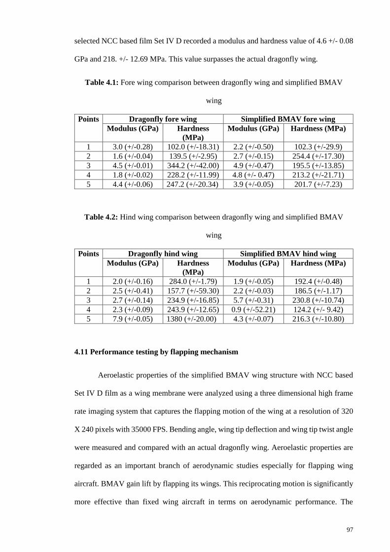
97
selected NCC based film Set IV D recorded a modulus and hardness value of 4.6 +/- 0.08
GPa and 218. +/- 12.69 MPa. This value surpasses the actual dragonfly wing.
Table 4.1: Fore wing comparison between dragonfly wing and simplified BMAV
wing
Points Dragonfly fore wing Simplified BMAV fore wing
Modulus (GPa) Hardness
(MPa)
Modulus (GPa) Hardness (MPa)
1 3.0 (+/-0.28) 102.0 (+/-18.31) 2.2 (+/-0.50) 102.3 (+/-29.9)
2 1.6 (+/-0.04) 139.5 (+/-2.95) 2.7 (+/-0.15) 254.4 (+/-17.30)
3 4.5 (+/-0.01) 344.2 (+/-42.00) 4.9 (+/-0.47) 195.5 (+/-13.85)
4 1.8 (+/-0.02) 228.2 (+/-11.99) 4.8 (+/- 0.47) 213.2 (+/-21.71)
5 4.4 (+/-0.06) 247.2 (+/-20.34) 3.9 (+/-0.05) 201.7 (+/-7.23)
Table 4.2: Hind wing comparison between dragonfly wing and simplified BMAV
wing
Points Dragonfly hind wing Simplified BMAV hind wing
Modulus (GPa) Hardness
(MPa)
Modulus (GPa) Hardness (MPa)
1 2.0 (+/-0.16) 284.0 (+/-1.79) 1.9 (+/-0.05) 192.4 (+/-0.48)
2 2.5 (+/-0.41) 157.7 (+/-59.30) 2.2 (+/-0.03) 186.5 (+/-1.17)
3 2.7 (+/-0.14) 234.9 (+/-16.85) 5.7 (+/-0.31) 230.8 (+/-10.74)
4 2.3 (+/-0.09) 243.9 (+/-12.65) 0.9 (+/-52.21) 124.2 (+/- 9.42)
5 7.9 (+/-0.05) 1380 (+/-20.00) 4.3 (+/-0.07) 216.3 (+/-10.80)
4.11 Performance testing by flapping mechanism
Aeroelastic properties of the simplified BMAV wing structure with NCC based
Set IV D film as a wing membrane were analyzed using a three dimensional high frame
rate imaging system that captures the flapping motion of the wing at a resolution of 320
X 240 pixels with 35000 FPS. Bending angle, wing tip deflection and wing tip twist angle
were measured and compared with an actual dragonfly wing. Aeroelastic properties are
regarded as an important branch of aerodynamic studies especially for flapping wing
aircraft. BMAV gain lift by flapping its wings. This reciprocating motion is significantly
more effective than fixed wing aircraft in terms on aerodynamic performance. The
98
flapping motion can be achieved by varieties of mechanism such as staggered crank,
outboard wing hinge, dual cranks and transverse shaft. These mechanism is heavy and
often used on a larger size BMAV. Electromagnetic actuated flapping mechanism as
discussed in section 3.6.9 produce the same reciprocating motion with lesser weight. This
mechanism is suitable in this research since mimicking dragonfly wing motion is one of
the objectives of this project. Dragonfly doesn’t fly in figure of 8 motion, the flapping
mechanism is straight forward rather than a complex ones. Static aeroelastic test of an
actual dragonfly wing and simplified dragonfly wing would be useful in mimicking the
flapping motion of dragonfly. Smith et al. (2000) conducted a study on a tethered desert
locust (Schistocerca gregaria) concluded that a flapping wing of an insect must undergo
an appropriate aeroelastic wing deformation to produce a suitable lift and thrust
generation. Several researchers concluded that the flexibility of the wing along with an
insect’s capability of changing their camber generates higher peak lift forces that rigid
and stiff wings (Mountcastle & Daniel, 2009; Young et al., 2009).
As mentioned in the literature review, dragonfly beats its wing in the range of 30
Hz and these fliers have a natural resonant frequency of 120 Hz. Comparisons were made
between actual dragonfly wing and simplified BMAV wing in a frequency range of 30
Hz, 60 Hz and 120 Hz. The oscillatory system fluctuates its frequency in approximation
of +/- 5 Hz for each steps. Figure 4.24 - 4.26 shows the aeroelastic properties of complete
wing design with membrane compared to actual dragonfly wings.
4.11.1 Bending angle
Bending angle in this research was analyzed on the chordwise direction during the
maximum dowstroke position (Dmax). Similar studies have been done by Kang and Shyy
(2013) who investigated chordwise flexibility for a simple wing structures. Figure 4.24
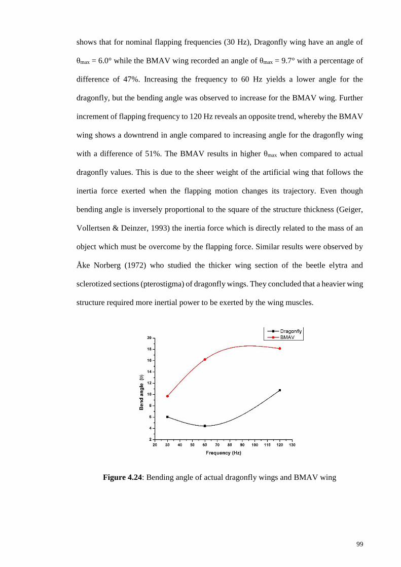
99
shows that for nominal flapping frequencies (30 Hz), Dragonfly wing have an angle of
θmax = 6.0° while the BMAV wing recorded an angle of θmax = 9.7° with a percentage of
difference of 47%. Increasing the frequency to 60 Hz yields a lower angle for the
dragonfly, but the bending angle was observed to increase for the BMAV wing. Further
increment of flapping frequency to 120 Hz reveals an opposite trend, whereby the BMAV
wing shows a downtrend in angle compared to increasing angle for the dragonfly wing
with a difference of 51%. The BMAV results in higher θmax when compared to actual
dragonfly values. This is due to the sheer weight of the artificial wing that follows the
inertia force exerted when the flapping motion changes its trajectory. Even though
bending angle is inversely proportional to the square of the structure thickness (Geiger,
Vollertsen & Deinzer, 1993) the inertia force which is directly related to the mass of an
object which must be overcome by the flapping force. Similar results were observed by
Åke Norberg (1972) who studied the thicker wing section of the beetle elytra and
sclerotized sections (pterostigma) of dragonfly wings. They concluded that a heavier wing
structure required more inertial power to be exerted by the wing muscles.
Figure 4.24: Bending angle of actual dragonfly wings and BMAV wing

100
4.11.2 Wing tip deflection
Deflection is another measurement that can be used to assess flapping wing
flexibility. Figure 4.25 shows the comparison of wing tip deflection between BMAV wing
and actual dragonfly wing. At Dmax, the magnitude of deflection at 30 Hz is almost similar
between BMAW wing and dragonfly wing. Increasing the flapping frequency to 60 Hz
shows a slight reduction in deflection for both wings. The trend continues to increase as
frequency increased to 120 Hz. The percentage of difference between deflection for 30,
60 and 120 Hz is 30%, 81% and 32% respectively. The largest deflection of actual
dragonfly wings is in the region of resonant frequency (at 120 Hz). The changes in wing
tip deflection is due to differences in rigidity on the wings by having a complex vein
design and corrugation along the wing surface (Richter & Lipson, 2011). The difference
in wing tip deflection between BMAV wing and actual dragonfly wing is primarily due
to rigidity differences. BMAV flexes more at the tip due to its concentrated PLA structure
there. Due to mass centralization on that section is higher, the tip tends to deflect more
when there is a sudden changes in path (i.e. during upstroke/downstroke motion).
Figure 4.25: Wing tip deflection of actual dragonfly wings and BMAV wing

101
4.11.3 Wing tip twist angle
Wing twist angle is an aerodynamic feature that has been show to potentially
enhance the thrust on a flapping wing aircraft (Yoon, Kang, & Jo, 2011). Morphing wing
design, defined as a technique of the wing to change its shape during flight, improves the
wing tip vortex swirling (Wlezien et al., 1998; Lian, & Shyy, 2007). This greatly depends
on the wing design. It is important to have an acceptable amount of wing twist angle for
a flapping wing efficiency. The maximum twist angle was recorded during the transition
of upstroke and downstroke. Figure 4.26 shows the wing tip twist angle of actual
dragonfly wing and BMAV wing. The twisting angle for actual dragonfly wing is θ =
154° for 30 Hz. However at 60 Hz twisting angle increases to 168° and remains at 167°
for resonant flapping frequency. The wing tip twist angle of the actual dragonfly wing
does not vary significantly as the flapping frequency is varied. For BMAV wing, the wing
tip twist angle 136° for 30 Hz with insignificant difference for 60Hz. The angle started to
dip significantly at resonant frequency, where the difference between actual dragonfly
and BMAV wing was 33%. Untwisted wings have large, drag producing wing surfaces
that will reduce the flight efficiency (Ismail et al., 2014). BMAV wing have a thicker
more rigid structure as oppose to dragonfly wings. This would prevent wing tip twist
further. Besides, the dip in twisting angle at higher frequency can be related to tremendous
amount of inertia force being generated on the simplified BMAV wing.
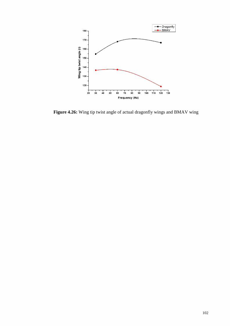
102
Figure 4.26: Wing tip twist angle of actual dragonfly wings and BMAV wing

103
CHAPTER 5: CONCLUSION
5.1 Summary
In this concluding chapter of this thesis, all of the experimental and analytical
work performed in this thesis is summarized. This chapter also lists the discoveries gained
in this original research and suggest improvements that can be done in future studies.
In this thesis, I have demonstrated that all of the objectives of bio-mimicking
actual dragonfly wing material and applying it as a membrane for a BMAV wing have
been achieved. Chitosan nanocomposite film was created using nanomaterials (CNW or
NCC) as a reinforcement and tannic acid as a chemical crosslinker. These additives
increases the mechanical properties of the film significantly. Moisture content, wettability
and solubility were also reduced. There is a good miscibility between CNW, NCC and
the chitosan matrix. The nano-mechanical properties of the BMAV membrane exceeded
those in an actual dragonfly wing membrane. The film’s excellent aeroelastic properties
(e.g. bending angle, wing tip deflection and wing tip twist angle) opens a promising new
realm of possibilities for BMAV wing design. Essentially, four different batches of
chitosan based nanocomposite film were produced. The first two have 12 sample sets and
the remaining last two batches have 8 sample sets. Each of these sample sets contains at
least 5 film samples, which have a unique nanomaterial and crosslinking dosage.
For the 1st batch, CNW and tannic acid played a major role in changing the
chemical and physical properties of chitosan based matrix. The use of CNW as an additive
filler material in the chitosan film matrix improves its mechanical properties. The aspect
ratio of CNW under TEM examination was approximately 8.8. Observation of the XRD
shows that the presence of CNW did not appreciably affect the apparent degree of

104
crystallinity of the chitosan matrix. CNW increases the rigidity and stiffness of the
chitosan film. The addition of CNW also reduces the water uptake and solubility of the
film. Crosslinking the chitosan film with tannic acid increases the rigidity of the film
structure and increases the mechanical properties of chitosan film. However, tannic acid
reduces these properties in the nanocomposite film. The XRD pattern shows that the
introduction of tannic acid changes the film into an anhydrous crystalline conformation.
Tannic acid also reduces the swelling behavior and solubility.
Heat treatment (for both CNW and NCC based film) appears to improve the
mechanical and physicochemical properties, regardless of the additives studied. FTIR
spectra shows significant changes in absorbance for the heat treated samples. This is due
to the evaporation of moisture retained in the chitosan matrix. XRD analysis for both
CNW and NCC shows different changes in the diffractogram pattern. NCC based films
show an increase in intensity peak for the heat treated samples, where CNW based films
didn’t have any significant changes. However both NCC and CNW based film shows
diminishing of peaks at 2θ= 11.4° for the heat treated samples. The heat treated samples
showed significant improvements in mechanical strength and reduction in moisture
uptake. This was due to accelerated crosslinking process that compacted the structure
even further.
For 2nd batch, the addition of NCC improves further the mechanical properties and
physicochemical properties of the chitosan based matrix. TEM image confirms that the
NCC particles are nanometer-scaled and possess a high aspect ratio of 20.9. The XRD
pattern shows that the addition of NCC induces a combination of amorphous and
crystalline regions in the chitosan matrix, which elevates the mechanical properties due
to the formation of a percolating network and strong filler matrix interaction compared to
CNW. The addition of NCC into the chitosan matrix also reduces the water solubility and
105
water uptake better than CNW. Crosslinking the nanocomposite film with tannic acid also
improves the mechanical and physicochemical properties.
Bio mimicked dragonfly-like wings requires high strength with an ultra-
lightweight membrane. A flapping frequency of 30 Hz continuously to produce lift
creates tremendous amount of stress on the wing for each beat. NCC, film properties are
well suited for use in BMAV wing membranes because the mechanical properties are
higher than its CNW counterpart. Chitosan film bonds well with the PLA wing frame.
Nanoindentation test on a variety of points on the wings of both an actual dragonfly and
BMAV revealed a comparable modulus and hardness. Different frequencies show major
differences in aeroelastic properties in static flapping test. This is due to the fact that the
mass of the wing membrane plays a larger role in creating inertial forces that overcome
elastic forces in both dragonfly and BMAV wings.
5.2 Other uses of film besides BMAV
The primary objective of this work is to create a bio-film inspired from dragonfly
wing membranes. Performance test on membrane only such as mechanical properties,
physiochemical evaluation, wettability, optical transmittance and nanoindentation sets a
new benchmark on chitosan based biofilm. The nanocomposite possess superior
mechanical properties and significant reduction in moisture uptake and solubility. Table
5.1 shows the improvement of chitosan based nanocomposite film in these test compared
to pure chitosan film and dragonfly wing membrane. These film could also be used for
different purposes, such as packaging material for food (since it is biocompatible and
nontoxic). Furthermore, chitosan nanocomposite film can be used for chelating metals
from water treatment plants especially lead ions since water resistivity had been improved
significantly.

106
Table 5.1: Benchmarking of chitosan based nanocomposite film with pure chitosan film
and actual dragonfly membrane.
Test Pure
chitosan
Nanocomposite Dragonfly
membrane
Tensile Strength 30.8 MPa 61.5 MPa (Batch 2 Set IV D) N/A
Young’s Modulus 664.9 MPa 2015.0 MPa (Batch 2 Set IV F) N/A
Moisture uptake 545.4% 94.0% (Batch 2 Set IV E) N/A
Solubility 21.5% 2.9% (Batch 2 Set IV E) N/A
Water contact angle 90.7° 100.3° 143.4°
Nanomechanical N/A 4.6 GPa (Batch 2 Set IV D) 2.6 GPa
5.3 Recommendation for future research
The established nanocomposite film can be further investigate into in-depth
characterization study on structural and chemical analysis. This would definitely give a
better understanding on molecular interaction and would open a new realm into
modifying chitosan matrix especially on the wettability aspect. Although the hydrophilic
nature of chitosan was improved by the addition of nanomaterial and crosslinker, the
moisture content of the film is still relatively high. Excess moisture content creates
warpage on the film. This issue can be addressed by making the surface of the film less
prone to water contact. Super hydrophobicity material can be found on a lotus leaf, where
often the contact angle of moisture on the surface is more than 150°. Investigating the
wax properties of a lotus plant and incorporating this into a chitosan film would be
interesting follow-on work that can be done. Wettability is directly proportional to surface
roughness (to an extent). A lot of studies have been conducted on bio mimicking micro
beads found on the rough surfaces of lotus leaves and shark fins to create a super
hydrophobic physical surface. Preventing the penetration of moisture on the film surface
would ensure that the water resistivity is high enough to prevent warpage.
Improvement of the PLA wing thickness should eliminate the unwanted inertial
forces that governs the aeroelastic properties of an artificial BMAV wing. I believe that
107
matching mass of a BMAV wing to that of a dragonfly wing would produce less
aeroelastic properties differences. This can be done by fabricating BMAV wings using a
higher resolution micro 3D printer or by a photolithography technique that can fabricate
micro or nano-sized shapes.

108
REFERENCES
Aelenei, N., Popa, M., Novac, O., Lisa, G., & Balaita, L. (2009). Tannic acid
incorporation in chitosan-based microparticles and in vitro controlled release.
Journal of Materials Science: Materials in Medicine, 20, 1095–1102.
Agrawal, A., & Agrawal, S. K. (2009). Design of Bio-inspired Flexible Wings for
Flapping-Wing Micro-sized Air Vehicle Applications. Advanced Robotics, 23(7-
8), 979-1002.
Åke Norberg, R. (1972). The pterostigma of insect wings an inertial regulator of wing
pitch. Journal of comparative physiology, 81(1), 9-22.
Arrieta, M. P., López, J., López, D., Kenny, J. M., & Peponi, L. (2015). Development of
flexible materials based on plasticized electrospun PLA–PHB blends: Structural,
thermal, mechanical and disintegration properties. European Polymer Journal,
73, 433-446
Azizi Samir, M. A. S., Alloin, F., & Dufresne, A. (2005). Review of Recent Research into
Cellulosic Whiskers, Their Properties and Their Application in Nanocomposite
Field. Biomacromolecules, 6(2), 612-626.
Azuma, A. (1992). Flight by Beating The Biokinetics of Flying and Swimming (pp. 77-
154): Springer Japan.
Bao, l., Hu, J.-s., Yu, Y.-l., Cheng, P., Xu, B.-q., & Tong, B.-g. (2006). Viscoelastic
constitutive model related to deformation of insect wing under loading in flapping
motion. Applied Mathematics and Mechanics, 27(6), 741-748.
Berg, C., & Rayner, J. (1995). The moment of inertia of bird wings and the inertial power
requirement for flapping flight. Journal of Experimental Biology, 198(8), 1655-
1664.
Birolli, W. G., Delezuk, J. A. d. M., & Campana-Filho, S. P. (2016). Ultrasound-assisted
conversion of alpha-chitin into chitosan. Applied Acoustics, 103, Part B, 239-242.
Bondeson, D., Mathew, A., & Oksman, K. (2006). Optimization of the isolation of
nanocrystals from microcrystalline cellulose by acid hydrolysis. Cellulose, 13(2),
171-180.

109
Božič, M., Gorgieva, S., & Kokol, V. (2012). Homogeneous and heterogeneous methods
for laccase-mediated functionalization of chitosan by tannic acid and quercetin.
Carbohydrate Polymers, 89(3), 854-864.
Bulota, M., & Budtova, T. (2015). Highly porous and light-weight flax/PLA composites.
Industrial Crops and Products, 74, 132-138.
Burger, A., & Fredericksen, J. M. (1948). Some N-Basically Substituted Derivatives of
o-Nitroaniline. Journal of the American Chemical Society, 70(1), 416-416.
Chang, C., H., Ting, K., E., & Chen, K., T., (2009). Study on Nanomechanical Properties
of Dragonfly Wing. Advanced Materials Research, (79)82, 1325-1328.
Chen, C., Dong, L., & Cheung, M. K. (2005). Preparation and characterization of
biodegradable poly(l-lactide)/chitosan blends. European Polymer Journal, 41(5),
958-966.
Chen, Y. H., Skote, M., Zhao, Y., & Huang, W. M. (2013). Dragonfly (Sympetrum
flaveolum) flight: Kinematic measurement and modelling. Journal of Fluids and
Structures, 40, 115-126.
Combes, S. A. (2010). Materials, Structure, and Dynamics of Insect Wings as
Bioinspiration for MAVs Encyclopedia of Aerospace Engineering: John Wiley &
Sons, Ltd.
Croisier, F., & Jérôme, C. (2013). Chitosan-based biomaterials for tissue engineering.
European Polymer Journal, 49(4), 780-792.
de Carvalho, R. A., & Grosso, C. R. F. (2004). Characterization of gelatin based films
modified with transglutaminase, glyoxal and formaldehyde. Food Hydrocolloids,
18(5), 717-726.
Dehnad, D., Mirzaei, H., Emam-Djomeh, Z., Jafari, S.-M., & Dadashi, S. (2014). Thermal
and antimicrobial properties of chitosan–nanocellulose films for extending shelf
life of ground meat. Carbohydrate Polymers, 109, 148-154.
de Mesquita, J. P., Donnici, C. L., & Pereira, F. V. (2010). Biobased Nanocomposites
from Layer-by-Layer Assembly of Cellulose Nanowhiskers with Chitosan.
Biomacromolecules, 11(2), 473-480.

110
Dickinson, M. H., Lehmann, F. O., & Gotz, K. G. (1993). The active control of wing
rotation by Drosophila. Journal of Experimental Biology, 182(1), 173-189.
Dietl, J. M., & Garcia, E. (2013). Ornithopter optimal trajectory control. Aerospace
Science and Technology, 26(1), 192-199.
Dirks, J.-H., & Taylor, D. (2012). Veins Improve Fracture Toughness of Insect Wings.
PLoS ONE, 7(8), e43411.
Domard, A. (2011). A perspective on 30 years research on chitin and chitosan.
Carbohydrate Polymers, 84(2), 696-703.
Dong, X. M., & Gray, D. G. (1997). Effect of Counterions on Ordered Phase Formation
in Suspensions of Charged Rodlike Cellulose Crystallites. Langmuir, 13(8), 2404-
2409.
Ehmann, H. M. A., Mohan, T., Koshanskaya, M., Scheicher, S., Breitwieser, D., Ribitsch,
V., Spirk, S. (2014). Design of anticoagulant surfaces based on cellulose
nanocrystals. Chemical Communications, 50(86), 13070-13072.
Geiger, M., Vollertsen, F., & Deinzer, G., (1993). Flexible Straightening of Car Body
Shells by Laser Forming. SAE Technical Paper 930279, 1993.
Ghosh, A., Ali, M. A., & Dias, G. J. (2009). Effect of Cross-Linking on Microstructure
and Physical Performance of Casein Protein. Biomacromolecules, 10(7), 1681-
1688.
Gopalan Nair, K., & Dufresne, A. (2003a). Crab Shell Chitin Whisker Reinforced Natural
Rubber Nanocomposites. 1. Processing and Swelling Behavior.
Biomacromolecules, 4(3), 657-665.
Gopalan Nair, K., & Dufresne, A. (2003b). Crab Shell Chitin Whisker Reinforced Natural
Rubber Nanocomposites. 2. Mechanical Behavior. Biomacromolecules, 4(3),
666-674.
Gopalan Nair, K., Dufresne, A., Gandini, A., & Belgacem, M. N. (2003). Crab Shell
Chitin Whiskers Reinforced Natural Rubber Nanocomposites. 3. Effect of
Chemical Modification of Chitin Whiskers. Biomacromolecules, 4(6), 1835-1842.
Gray, D. (2008). Transcrystallization of polypropylene at cellulose nanocrystal surfaces.
Cellulose, 15(2), 297-301.

111
Greenewalt, C.H. (1962). Dimensional relationships for flying animals. Smithsonian
Miscellaneous Collections, 144 (2) pp. 1–46
Gui, L., Fink, T., Cao, Z., Sun, D., Seiner, J. M., & Streett, D. A. (2010). Fire ant alate
wing motion data and numerical reconstruction. Journal of Insect Science, 10(1).
Habibi, Y., Lucia, L. A., & Rojas, O. J. (2010). Cellulose Nanocrystals: Chemistry, Self-
Assembly, and Applications. Chemical Reviews, 110(6), 3479-3500.
Hariraksapitak, P., & Supaphol, P. (2010). Preparation and properties of α-chitin-
whisker-reinforced hyaluronan–gelatin nanocomposite scaffolds. Journal of
Applied Polymer Science, 117(6), 3406-3418.
Helbert, W., & Chanzy, H. (1994). Oriented growth of V amylose n-butanol crystals on
cellulose. Carbohydrate Polymers, 24(2), 119-122.
Hirano, S. (2001). Wet-spinning and applications of functional fibers based on chitin and
chitosan. Macromolecular Symposia, 168(1), 21-30.
Hou, D., Yin, Y., Zhao, H., & Zhong, Z. (2015). Effects of blood in veins of dragonfly
wing on the vibration characteristics. Computers in Biology and Medicine, 58, 14-
19.
Ifuku, S., Shervani, Z., & Saimoto, H. (2013). Chitin Nanofibers, Preparations and
Applications, Advances in Nanofibers. In R. Maguire (Ed.). Advances in
Nanofibers. InTech (Chapter 3)
Ismail, N. I., Zulkifli, A. H., Abdullah, M. Z., Basri, M. H., & Abdullah, N. S. (2014).
Optimization of aerodynamic efficiency for twist morphing MAV wing. Chinese
Journal of Aeronautics, 27(3), 475-487.
Jaderic, D., & Huang, P. (2011). Figure-8 Flapping Micro Air Vehicle 49th AIAA
Aerospace Sciences Meeting including the New Horizons Forum and Aerospace
Exposition: American Institute of Aeronautics and Astronautics.
Joslin, D. L., & Oliver, W. C. (1990). A new method for analyzing data from continuous
depth-sensing microindentation tests. Journal of Materials Research, 5(01), 123-
126.
112
Kadokawa, J.-i., Takegawa, A., Mine, S., & Prasad, K. (2011). Preparation of chitin
nanowhiskers using an ionic liquid and their composite materials with poly(vinyl
alcohol). Carbohydrate Polymers, 84(4), 1408-1412.
Kang, C.-k., & Shyy, W. (2013). Scaling law and enhancement of lift generation of an
insect-size hovering flexible wing. Journal of The Royal Society Interface, 10(85).
Kao, C.-T., Lin, C.-C., Chen, Y.-W., Yeh, C.-H., Fang, H.-Y., & Shie, M.-Y. (2015).
Poly(dopamine) coating of 3D printed poly(lactic acid) scaffolds for bone tissue
engineering. Materials Science and Engineering: C, 56, 165-173.
Kaya, M., Mujtaba, M., Bulut, E., Akyuz, B., Zelencova, L., & Sofi, K. (2015).
Fluctuation in physicochemical properties of chitins extracted from different body
parts of honeybee. Carbohydrate Polymers, 132, 9-16.
Kempf, M., (2000), Biological materials, determination of Young’s moduli of the insect
cuticle (dragonflies, Anisoptera), Application note, Hysitron Inc,
www.hysitron.com.
Kesel, A. B., Philippi, U., & Nachtigall, W. (1998). Biomechanical aspects of the insect
wing: an analysis using the finite element method. Computers in Biology and
Medicine, 28(4), 423-437.
Khan, A., Khan, R. A., Salmieri, S., Le Tien, C., Riedl, B., Bouchard, J., Lacroix, M.
(2012). Mechanical and barrier properties of nanocrystalline cellulose reinforced
chitosan based nanocomposite films. Carbohydrate Polymers, 90(4), 1601-1608.
Kim, K. M., Weller, C. L., Hanna, M. A., & Gennadios, A. (2002). Heat Curing of Soy
Protein Films at Selected Temperatures and Pressures. LWT - Food Science and
Technology, 35(2), 140-145.
Kim, D.-K., Kim, H.-I., Han, J.-H., & Kwon, K.-J. (2008). Experimental Investigation on
the Aerodynamic Characteristics of a Bio-mimetic Flapping Wing with Macro-
fiber Composites. Journal of Intelligent Material Systems and Structures, 19(3),
423-431.
Kubota, N., Kikuchi, Y., Mizuhara, Y., Ishihara, T., & Takita, Y. (1993). Solid-phase
modification of chitosan hydrogel membranes and permeability properties of
modified chitosan membranes. Journal of Applied Polymer Science, 50(9), 1665-
1670.

113
Kumar, D., Shah, M., Mohite, P.M., & Kamle, S. (2014). Structural dynamic analysis of
bio inspired carbon fiber/polyethylene MAV wings. International Journal of
Recent advances in Mechanical Engineering (IJMECH), 3(4)
Kumar, M. N. V. R., Muzzarelli, R. A. A., Muzzarelli, C., Sashiwa, H., & Domb, A. J.
(2004). Chitosan Chemistry and Pharmaceutical Perspectives. Chemical Reviews,
104(12), 6017-6084.
Kushleyev, A., Mellinger, D., Powers, C., & Kumar, V. (2013). Towards a swarm of agile
micro quadrotors. Autonomous Robots, 35(4), 287-300.
Li, X., Qiu, C., Ji, N., Sun, C., Xiong, L., & Sun, Q. (2015). Mechanical, barrier and
morphological properties of starch nanocrystals-reinforced pea starch films.
Carbohydrate Polymers, 121, 155-162.
Li, Q., Zhou, J., & Zhang, L. (2009). Structure and properties of the nanocomposite films
of chitosan reinforced with cellulose whiskers. Journal of Polymer Science Part
B: Polymer Physics, 47(11), 1069-1077.
Lian, Y., & Shyy, W. (2007). Laminar-Turbulent Transition of a Low Reynolds Number
Rigid or Flexible Airfoil. AIAA Journal, 45(7), 1501-1513.
Lin, E., Li, Y., Ortiz, C., & Boyce, M. C. (2014). 3D printed, bio-inspired prototypes and
analytical models for structured suture interfaces with geometrically-tuned
deformation and failure behavior. Journal of the Mechanics and Physics of Solids,
73, 166-182.
Leung, A. W., Lam, E., Chong, J., Hrapovic, S., & Luong, J. T. (2013). Reinforced
plastics and aerogels by nanocrystalline cellulose. Journal of Nanoparticle
Research, 15(5), 1-24.
Levy, D.-E., & Seifert, A. (2010). Parameter study of simplified dragonfly airfoil
geometry at Reynolds number of 6000. Journal of Theoretical Biology, 266(4),
691-702.
Lorevice, M. V., Otoni, C. G., Moura, M. R. d., & Mattoso, L. H. C. (2016). Chitosan
nanoparticles on the improvement of thermal, barrier, and mechanical properties
of high- and low-methyl pectin films. Food Hydrocolloids, 52, 732-740. d
Lu, Y., Weng, L., & Zhang, L. (2004). Morphology and Properties of Soy Protein Isolate
Thermoplastics Reinforced with Chitin Whiskers. Biomacromolecules, 5(3),
1046-1051.
114
Lu, Y., Weng, L., & Zhang, L. (2004). Morphology and Properties of Soy Protein Isolate
Thermoplastics Reinforced with Chitin Whiskers. Biomacromolecules, 5(3),
1046-1051.
Luo, C., & Wei, C. (2015). Intraspecific sexual mimicry for finding females in a cicada:
males produce ‘female sounds’ to gain reproductive benefit. Animal Behaviour,
102, 69-76.
Ma, B., Qin, A., Li, X., Zhao, X., & He, C. (2014). Structure and properties of chitin
whisker reinforced chitosan membranes. International Journal of Biological
Macromolecules, 64, 341-346.
Ma, H., Zhou, B., Li, H.-S., Li, Y.-Q., & Ou, S.-Y. (2011). Green composite films
composed of nanocrystalline cellulose and a cellulose matrix regenerated from
functionalized ionic liquid solution. Carbohydrate Polymers, 84(1), 383-389.
Marchessault, R. H., Morehead, F. F., & Walter, N. M. (1959). Liquid Crystal Systems
from Fibrillar Polysaccharides. Nature, 184(4686), 632-633.
Martínez Urreaga, J., & de la Orden, M. U. (2007). Modification of cellulose with amino
compounds: A fluorescence study. Carbohydrate Polymers, 69(1), 14-19.
Mathew, A. P., Laborie, M.-P. G., & Oksman, K. (2009). Cross-Linked Chitosan/Chitin
Crystal Nanocomposites with Improved Permeation Selectivity and pH Stability.
Biomacromolecules, 10(6), 1627-1632.
Maxworthy, T. (1981). The Fluid Dynamics of Insect Flight. Annual Review of Fluid
Mechanics, 13(1), 329-350.
Möller, H., Grelier, S., Pardon, P., & Coma, V. (2004). Antimicrobial and
Physicochemical Properties of Chitosan−HPMC-Based Films. Journal of
Agricultural and Food Chemistry, 52(21), 6585-6591.
Moon, R. J., Martini, A., Nairn, J., Simonsen, J., & Youngblood, J. (2011). Cellulose
nanomaterials review: structure, properties and nanocomposites. Chemical
Society Reviews, 40(7), 3941-3994.
Mountcastle, A., & Daniel, T. (2009). Aerodynamic and functional consequences of wing
compliance. Experiments in Fluids, 46(5), 873-882.

115
Mucha, M., Piekielna, J., & Wieczorek, A. (1999). Characterisation and morphology of
biodegradable chitosan / synthetic polymer blends. Macromolecular Symposia,
144(1), 391-412.
Muzzarelli, R. A. A. (2009). Genipin-crosslinked chitosan hydrogels as biomedical and
pharmaceutical aids. Carbohydrate Polymers, 77(1), 1-9.
Muzzarelli, R. A. (2011). Chitin Nanostructures in Living Organisms. In N. S. Gupta
(Ed.), Chitin (Vol. 34, pp. 1-34): Springer Netherlands.
Muzzarelli, R. A. A. (2011). Biomedical Exploitation of Chitin and Chitosan via
Mechano-Chemical Disassembly, Electrospinning, Dissolution in Imidazolium
Ionic Liquids, and Supercritical Drying. Marine Drugs, 9(9), 1510.
Muzzarelli, R., Mehtedi, M., & Mattioli-Belmonte, M. (2014). Emerging Biomedical
Applications of Nano-Chitins and Nano-Chitosans Obtained via Advanced Eco-
Friendly Technologies from Marine Resources. Marine Drugs, 12(11), 5468.
Nagai, H., Nishi, A., Fujimoto, T., Isogai, K., (2009). Study on flow interaction
mechanism of fore- and hindwings of dragonfly. In: Proceedings of the 4th
International Symposium on Aero Aqua Bio-Mechanisms, Shanghai, China.
Nguyen, H.-N., Ha, C., & Lee, D. (2015). Mechanics, control and internal dynamics of
quadrotor tool operation. Automatica, 61, 289-301.
Nikonenko, N. A., Buslov, D. K., Sushko, N. I., & Zhbankov, R. G. (2005). Spectroscopic
manifestation of stretching vibrations of glycosidic linkage in polysaccharides.
Journal of Molecular Structure, 752(1–3), 20-24.
Ogawa, K., Yui, T., & Okuyama, K. (2004). Three D structures of chitosan. International
Journal of Biological Macromolecules, 34(1–2), 1-8.
Oliver, W. C., & Pharr, G. M. (1992). An improved technique for determining hardness
and elastic modulus using load and displacement sensing indentation experiments.
Journal of Materials Research, 7(06), 1564-1583.
Paillet, M., & Dufresne, A. (2001). Chitin Whisker Reinforced Thermoplastic
Nanocomposites. Macromolecules, 34(19), 6527-6530.
Pawlak, A., & Mucha, M. (2003). Thermogravimetric and FTIR studies of chitosan
blends. Thermochimica Acta, 396(1–2), 153-166.

116
Pennycuick, C. J. (1969). THE MECHANICS OF BIRD MIGRATION. Ibis, 111(4), 525-
556.
Pereda, M., Dufresne, A., Aranguren, M. I., & Marcovich, N. E. (2014). Polyelectrolyte
films based on chitosan/olive oil and reinforced with cellulose nanocrystals.
Carbohydrate Polymers, 101, 1018-1026.
Peña, C., de la Caba, K., Eceiza, A., Ruseckaite, R., & Mondragon, I. (2010). Enhancing
water repellence and mechanical properties of gelatin films by tannin addition.
Bioresource Technology, 101(17), 6836-6842.
Pillai, C. K. S., Paul, W., & Sharma, C. P. (2009). Chitin and chitosan polymers:
Chemistry, solubility and fiber formation. Progress in Polymer Science, 34(7),
641-678.
Pines, D. J., & Bohorquez, F. (2006). Challenges Facing Future Micro-Air-Vehicle
Development. Journal of Aircraft, 43(2), 290-305.
Pornsin-sirirak, T. N., Tai, Y. C., Nassef, H., & Ho, C. M. (2001). Titanium-alloy MEMS
wing technology for a micro aerial vehicle application. Sensors and Actuators A:
Physical, 89(1–2), 95-103.
Pradal, C., Kithva, P., Martin, D., Trau, M., & Grondahl, L. (2011). Improvement of the
wet tensile properties of nanostructured hydroxyapatite and chitosan
biocomposite films through hydrophobic modification. [10.1039/C0JM03080E].
Journal of Materials Chemistry, 21(7), 2330-2337.
Rajabi, H., Moghadami, M., & Darvizeh, A. (2011). Investigation of Microstructure,
Natural Frequencies and Vibration Modes of Dragonfly Wing. Journal of Bionic
Engineering, 8(2), 165-173.
Reay, D. A. (1977). 2 - Leonardo da Vinci: — a Scientist among Sceptical Philosophers.
In D. A. Reay (Ed.), The History of Man-Powered Flight (pp. 11-29): Pergamon.
Reddy, N., & Yang, Y. (2010). Citric acid cross-linking of starch films. Food Chemistry,
118(3), 702-711.
Richter, C., & Lipson, H. (2011). Untethered hovering flapping flight of a 3D-printed
mechanical insect. Artif. Life, 17(2), 73-86.
Rinaudo, M. (2006). Chitin and chitosan: Properties and applications. Progress in
Polymer Science, 31(7), 603-632.

117
Ritthidej, G. C., Phaechamud, T., & Koizumi, T. (2002). Moist heat treatment on
physicochemical change of chitosan salt films. International Journal of
Pharmaceutics, 232(1–2), 11-22.
Rittschof, C. C., & Seeley, T. D. (2008). The buzz-run: how honeybees signal ‘Time to
go!’. Animal Behaviour, 75(1), 189-197.
Rivero, S., García, M. A., & Pinotti, A. (2010). Crosslinking capacity of tannic acid in
plasticized chitosan films. Carbohydrate Polymers, 82(2), 270-276.
Rivero, S., García, M. A., & Pinotti, A. (2011). Heat Treatment To Modify the Structural
and Physical Properties of Chitosan-Based Films. Journal of Agricultural and
Food Chemistry, 60, 492–499.
Rivero, S., García, M. A., & Pinotti, A. (2012). Heat Treatment To Modify the Structural
and Physical Properties of Chitosan-Based Films. Journal of Agricultural and
Food Chemistry, 60(1), 492-499.
Rivero, S., Garc¨ªa, M. A., & Pinotti, A. (2013). Physical and Chemical Treatments on
Chitosan Matrix to Modify Film Properties and Kinetics of Biodegradation.
Journal of Materials Physics and Chemistry, 1(3), 51-57.
Roy, S. K., Todd, J. G., & Glasser, W. G. (1998). Crosslinked hydrogel beads from
chitosan: Google Patents.
Saha, R., & Nix, W. D. (2002). Effects of the substrate on the determination of thin film
mechanical properties by nanoindentation. Acta Materialia, 50(1), 23-38.
Sajomsang, W., & Gonil, P. (2010). Preparation and characterization of α-chitin from
cicada sloughs. Materials Science and Engineering: C, 30(3), 357-363.
Salaberria, A. M., Diaz, R. H., Labidi, J., & Fernandes, S. C. M. (2015). Role of chitin
nanocrystals and nanofibers on physical, mechanical and functional properties in
thermoplastic starch films. Food Hydrocolloids, 46, 93-102.
Saravanan, D., Hemalatha, R., & Sudha, P. N. (2011). Synthesis and characterization of
cross linked chitin / bentonite polymer blend and adsorption studies of Cu (II) and
Cr (VI) on chitin. Der Pharma Chemica, 3, 406–423.
Shutava, T., Prouty, M., Kommireddy, D., & Lvov, Y. (2005). pH Responsive
Decomposable Layer-by-Layer Nanofilms and Capsules on the Basis of Tannic
Acid. Macromolecules, 38(7), 2850-2858.
118
Sionkowska, A., Płanecka, A., Lewandowska, K., & Michalska, M. (2014). The influence
of UV-irradiation on thermal and mechanical properties of chitosan and silk
fibroin mixtures. Journal of Photochemistry and Photobiology B: Biology, 140,
301-305.
Šimkovic, I. (2008). What could be greener than composites made from polysaccharides?
Carbohydrate Polymers, 74(4), 759-762.
Šimkovic, I. (2013). Unexplored possibilities of all-polysaccharide composites.
Carbohydrate Polymers, 95(2), 697-715.
Smith, C. W., Herbert, R., Wootton, R. J., & Evans, K. E. (2000). The hind wing of the
desert locust (Schistocerca gregaria Forskal). II. Mechanical properties and
functioning of the membrane. Journal of Experimental Biology, 203(19), 2933-
2943.
Sriupayo, J., Supaphol, P., Blackwell, J., & Rujiravanit, R. (2005). Preparation and
characterization of α-chitin whisker-reinforced chitosan nanocomposite films
with or without heat treatment. Carbohydrate Polymers, 62(2), 130-136.
Song, F., Lee, K. L., Soh, A. K., Zhu, F., & Bai, Y. L. (2004). Experimental studies of
the material properties of the forewing of cicada (Homóptera, Cicàdidae). Journal
of Experimental Biology, 207(17), 3035-3042.
Song, F., Xiao, K. W., Bai, K., & Bai, Y. L. (2007). Microstructure and nanomechanical
properties of the wing membrane of dragonfly. Materials Science and
Engineering: A, 457(1–2), 254-260.
Stansbury, J. W., & Idacavage, M. J. (2015). 3D printing with polymers: Challenges
among expanding options and opportunities. Dental Materials. In Press,
Corrected Proof
Sudo, S., Tsuyuki, K., Ikohagi, T., Ohta, F., Shida, S., & Tani, J. (1999). A Study on the
Wing Structure and Flapping Behavior of a Dragonfly. JSME International
Journal Series C, 42(3), 721-729.
Sunada, S., Zeng, L., & Kawachi, K. (1998). The Relationship Between Dragonfly Wing
Structure and Torsional Deformation. Journal of Theoretical Biology, 193(1), 39-
45.

119
Sung, H.-W., Huang, R.-N., Huang, L. L. H., & Tsai, C.-C. (1999). In vitro evaluation of
cytotoxicity of a naturally occurring cross-linking reagent for biological tissue
fixation. Journal of Biomaterials Science, Polymer Edition, 10(1), 63-78.
Sun, J. Y., Pan, C. X., Tong, J., & Zhang, J. (2010). Coupled model analysis of the
structure and nano-mechanical properties of dragonfly wings. IET
Nanobiotechnol, 4(1), 10-18.
Sun, J., & Bhushan, B. (2012). The structure and mechanical properties of dragonfly
wings and their role on flyability. Comptes Rendus Mécanique, 340(1–2), 3-17.
Teng, Y., Zhang, Y., Heng, L., Meng, X., Yang, Q., & Jiang, L. (2015). Conductive
Polymer Porous Film with Tunable Wettability and Adhesion. Materials, 8(4),
1817
Thakhiew, W., Devahastin, S., & Soponronnarit, S. (2013). Physical and mechanical
properties of chitosan films as affected by drying methods and addition of
antimicrobial agent. Journal of Food Engineering, 119(1), 140-149.
Thakhiew, W., Champahom, M., Devahastin, S., & Soponronnarit, S. (2015).
Improvement of mechanical properties of chitosan-based films via physical
treatment of film-forming solution. Journal of Food Engineering, 158, 66-72.
Thomas, A. L. R., Taylor, G. K., Srygley, R. B., Nudds, R. L., & Bomphrey, R. J. (2004).
Dragonfly flight: free-flight and tethered flow visualizations reveal a diverse array
of unsteady lift-generating mechanisms, controlled primarily via angle of attack.
Journal of Experimental Biology, 207(24), 4299-4323.
Toffey, A., & Glasser, W. G. (1999). Chitin derivatives. II. Time–temperature–
transformation cure diagrams of the chitosan amidization process. Journal of
Applied Polymer Science, 73(10), 1879-1889. 3
Umamaheshwar R. R. S., & Chandra M. R. G. (2014). Synthesis of Chitin Nano Particles
for Preparation of Nano PF Composites. IOSR Journal of Polymer and Textile
Engineering, 1(2), 11-14.
Vilaplana, F., Strömberg, E., & Karlsson, S. (2010). Environmental and resource aspects
of sustainable biocomposites. Polymer Degradation and Stability, 95(11), 2147-
2161.

120
Voronova, M. I., Surov, O. V., Guseinov, S. S., Barannikov, V. P., & Zakharov, A. G.
(2015). Thermal stability of polyvinyl alcohol/nanocrystalline cellulose
composites. Carbohydrate Polymers, 130, 440-447.
Wang, S.-F., Shen, L., Zhang, W.-D., & Tong, Y.-J. (2005). Preparation and Mechanical
Properties of Chitosan/Carbon Nanotubes Composites. Biomacromolecules, 6(6),
3067-3072.
Ward, T. A., Rezadad, M., Fearday, C. J., & Viyapuri, R. (2015). A Review of
Biomimetic Air Vehicle Research: 1984-2014. International Journal of Micro Air
Vehicles, 7(3), 375-394.
Watthanaphanit, A., Supaphol, P., Tamura, H., Tokura, S., & Rujiravanit, R. (2008).
Fabrication, structure, and properties of chitin whisker-reinforced alginate
nanocomposite fibers. Journal of Applied Polymer Science, 110(2), 890-899.
Wei, Y. C., Hudson, S. M., Mayer, J. M., & Kaplan, D. L. (1992). The crosslinking of
chitosan fibers. Journal of Polymer Science Part A: Polymer Chemistry, 30(10),
2187-2193.
Welsh, E. R., & Price, R. R. (2003). Chitosan Cross-Linking with a Water-Soluble,
Blocked Diisocyanate. 2. Solvates and Hydrogels. Biomacromolecules, 4(5),
1357-1361.
Wlezien, R., Horner, G., McGowan, A., Padula, S., Scott, M., Silcox, R., & Simpson, J.
(1998). The Aircraft Morphing Program 39th AIAA/ASME/ASCE/AHS/ASC
Structures, Structural Dynamics, and Materials Conference and Exhibit:
American Institute of Aeronautics and Astronautics.
Wongpanit, P., Sanchavanakit, N., Pavasant, P., Bunaprasert, T., Tabata, Y., &
Rujiravanit, R. (2007). Preparation and characterization of chitin whisker-
reinforced silk fibroin nanocomposite sponges. European Polymer Journal,
43(10), 4123-4135.
Wu, J., Peng, H., Chen, Q., & Peng, X. (2014). Modeling and control approach to a
distinctive quadrotor helicopter. ISA Transactions, 53(1), 173-185.
Wu, X., Moon, R., & Martini, A. (2013). Crystalline cellulose elastic modulus predicted
by atomistic models of uniform deformation and nanoscale indentation. Cellulose,
20(1), 43-55.
121
Xinyan, D., Schenato, L., & Sastry, S. S. (2006). Flapping flight for biomimetic robotic
insects: part II-flight control design. Robotics, IEEE Transactions on, 22(4), 789-
803.
Yahyanejad, S., & Rinner, B. (2015). A fast and mobile system for registration of low-
altitude visual and thermal aerial images using multiple small-scale UAVs. ISPRS
Journal of Photogrammetry and Remote Sensing, 104, 189-202.
Yang, C. Q., Wang, X., & Kang, I.-S. (1997). Ester Crosslinking of Cotton Fabric by
Polymeric Carboxylic Acids and Citric Acid. Textile Research Journal, 67(5),
334-342.
Yoon, S., Kang, L.-H., & Jo, S. (2011). Development of Air Vehicle with Active Flapping
and Twisting of Wing. Journal of Bionic Engineering, 8(1), 1-9.
Young, J., Walker, S. M., Bomphrey, R. J., Taylor, G. K., & Thomas, A. L. R. (2009).
Details of Insect Wing Design and Deformation Enhance Aerodynamic Function
and Flight Efficiency. Science, 325(5947), 1549-1552.
Zakaria, Z., Izzah, Z., Jawaid, M., & Hassan, A. (2012). Effect of degree of deacetylation
of Chitosan on thermal stability and compatibility of Chitosan-Polyamide blend.
Bioresources.com, 7(4), 5568-5580.
Zeng, J.-B., He, Y.-S., Li, S.-L., & Wang, Y.-Z. (2012). Chitin Whiskers: An Overview.
Biomacromolecules, 13(1), 1-11.
Zhao, J., He, X., Wang, Y., Zhang, W., Zhang, X., Zhang, X., Lu, C. (2014).
Reinforcement of all-cellulose nanocomposite films using native cellulose
nanofibrils. Carbohydrate Polymers, 104, 143-150.
Zhong, L., Fu, S., Peng, X., Zhan, H., & Sun, R. (2012). Colloidal stability of negatively
charged cellulose nanocrystalline in aqueous systems. Carbohydrate Polymers,
90(1), 644-649.
Zhu, L., Liang, K., & Ji, Y. (2015). Prominent reinforcing effect of chitin nanocrystals on
electrospun polydioxanone nanocomposite fiber mats. Journal of the Mechanical
Behavior of Biomedical Materials, 44, 35-42.

122
LIST OF PUBLICATIONS, CONFERENCE PRESENTATION AND PATENTS
First author
[1] Rubentheren, V., Ward, T. A., Chee, C. Y., & Tang, C. K. (2015). Processing and
analysis of chitosan nanocomposites reinforced with chitin whiskers and tannic
acid as a crosslinker. Carbohydrate Polymers, 115, 379-387. (Q1 Journal: 4.074
IF)
[2] Rubentheren, V., Ward, T., Chee, C., & Nair, P. (2015). Physical and chemical
reinforcement of chitosan film using nanocrystalline cellulose and tannic acid.
Cellulose, 22(4), 2529-2541. (Q1 Journal:3.573 IF)
[3] Rubentheren, V., Ward, T., Chee, C., Nair, P., Salami, E., & Fearday, C. (2015).
Effects of heat treatment on chitosan nanocomposite film reinforced with
nanocrystalline cellulose and tannic acid. Carbohydrate Polymers, 140,202-208
(Q1 Journal: 4.074 IF)
[4] Rubentheren, V., Ward, T. A., Chee, C. Y., Reinforcement of chitosan based
nano-composite film using heat treatment for the wing membrane of biomimetic
micro air vehicle (BMAV). Material characterizations (Submitted to Q1
Journal, 1.845 IF)
[5] Rubentheren, V., Ward, T., Chee, C., Nair, P., Erfan, S., (2015). Development
of heat treated chitosan nano-composite film for the wing membrane of
biomimetic micro air vehicle (BMAV). European conference on organized film
ECOF 14.
Contributing author
[1] Ward, T. A., Rezadad, M., Fearday, C. J., & Viyapuri, R. (2015). A Review of
Biomimetic Air Vehicle Research: 1984-2014. International Journal of Micro Air
Vehicles, 7(3), 375-394. (Q3 Journal:0.486 IF)
[2] Nair, P., Ward, T., Rubentheren, V. (2015). Static Strength Analysis of Dragonfly
Inspired wing for Biomimetic Micro Air Vehicles. Chinese Journal of
Aeronautics. (Q1 Journal:1.070 IF)
[3] Nair, P., Ward, T., Rubentheren, V., Johan, M., R. (2015). Experimental analysis
of artificial dragonfly wings using black graphite and fibreglass for use in
Biomimetic Micro Air Vehicles (BMAV). MATEC Web of Conferences
30,03001.

123
Patents
Two patents have been applied. First round of presentation have been completed.
Ongoing process for next step:
[1] Rubentheren, V., Ward, T., Chee, C., (2015) Chitosan nanocomposite film with
chitin nanowhiskers and tannic acid as a crosslinker
[2] Rubentheren, V., Ward, T., Chee, C., (2015) Chitosan nanocomposite film with
nanocrystalline cellulose and tannic acid as a crosslinker

124
APPENDICES
Appendix A: Force displacement graph of dragonfly forewing
A1. Point 1 (Costa)
A2. Point 2 (Wing tip)

125
A3. Point 3 (Nodus)
A4. Point 4 (Postal vein)
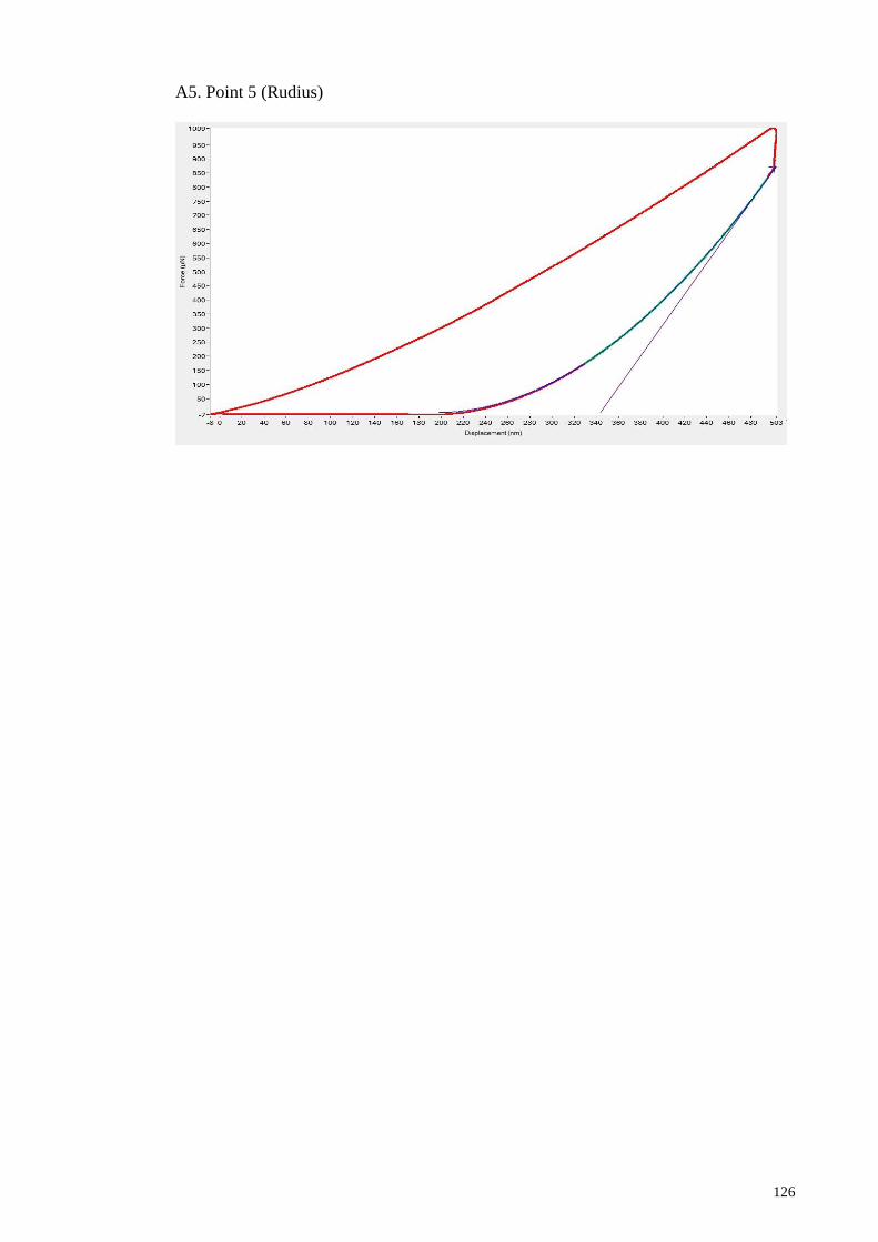
126
A5. Point 5 (Rudius)

127
Appendix B: Force displacement graph of dragonfly hind wing
B1. Point 1 (Costa)
B2. Wing tip
B3. Point 3 Nodus

128
B4. Point 4 (Postal vein)
B5. Point 5 (Rudius)

129

130
Appendix C: Force displacement graph of BMAV fore wing
C1. Point 1
C2. Point 2

131
C3. Point 3
C4. Point 4

132
C5. Point 5

133
Appendix D: Force displacement graph of BMAV hind wing
D1. Point 1
D2. Point 2
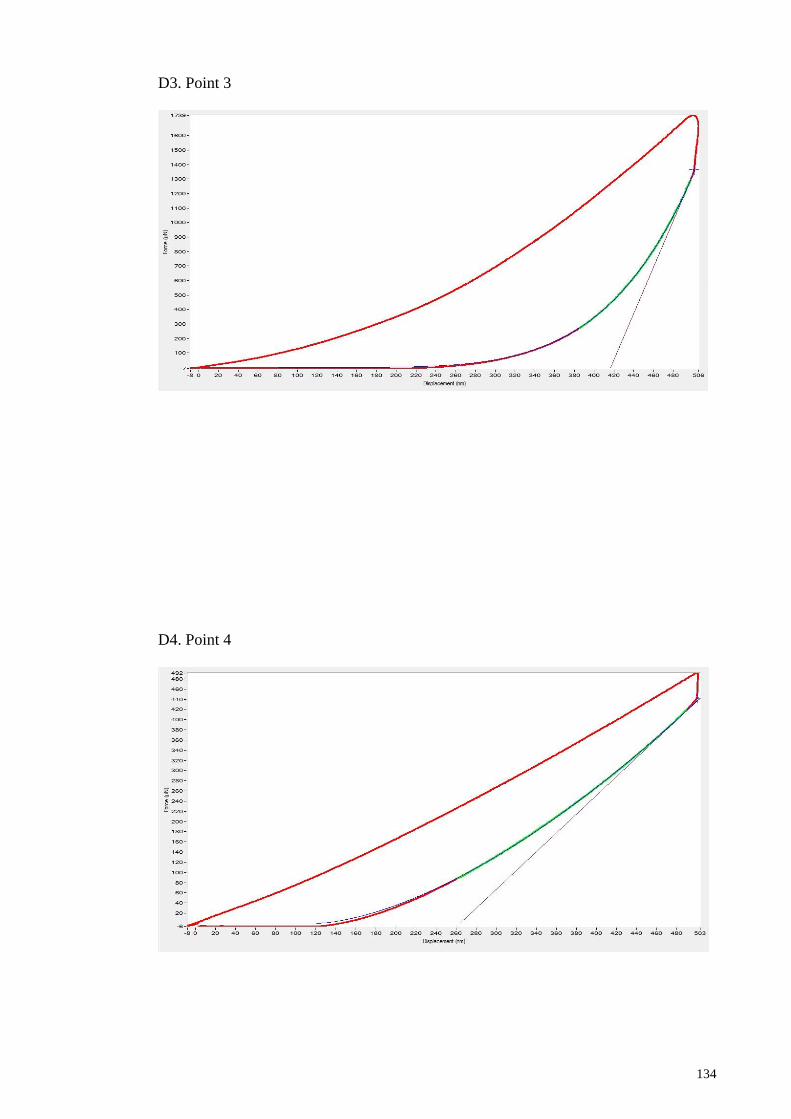
134
D3. Point 3
D4. Point 4
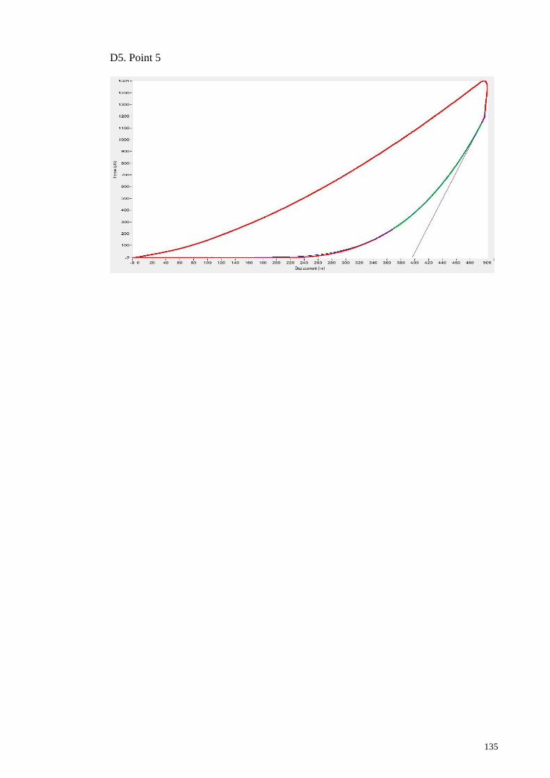
135
D5. Point 5