Embed Size (px)
Citation preview

DPR Dated May, 2015DPR Dated May, 2015DPR Dated May, 2015
June 19, 2015 TCIL DPR on A&N Submarine Fiber Connectivity, Private & Confidential Page 2
TABLE OF CONTENTS
1. EXECUTIVE SUMMARY 5
1.1. BACKGROUND 51.2. METHODOLOGY TO PREPARE DPR 61.3. BROAD FINDINGS 71.3.1. PROPOSED ROUTE DIAGRAM 71.3.2. ROUTE LENGTH 81.3.3. SYSTEM DIMENSIONING 81.4. RECOMMENDATIONS 131.5. STRUCTURE OF THE REPORT 13
2. INTRODUCTION 15
2.1. ABOUT ANDAMAN & NICOBAR ISLANDS 152.2. PRESENT TELECOM SCENARIO IN ANI 152.3. ISSUES WITH PRESENT TELECOM CONNECTIVITY IN ANI 162.4. FUTURE BANDWIDTH REQUIREMENTS OF ANI 162.5. NEED OF RELIABLE TELECOM CONNECTIVITY 202.6. SUBMARINE OPTICAL FIBER COMMUNICATION SYSTEM 202.6.1. WET PLANT COMPONENTS 212.6.2. DRY PLANT COMPONENTS 232.6.3. MARINE OPERATIONS AND MAINTENANCE 242.7. APPROACH OF CONNECTIVITY ON SUBMARINE FIBER TO ANI 24
3. DEDICATED SUBMARINE OPTICAL FIBER CABLE TO ANI 26
3.1. PROJECT OVERVIEW 263.1.1. NETWORK COMMUNICATION ARCHITECTURE 273.1.1.1. SUBMARINE CONNECTIVITY 273.1.1.2. OVERALL EQUIPMENT SCHEMATIC 273.1.1.3. SYSTEM CONFIGURATION 283.1.2. DESIGN CONSIDERATIONS 293.1.2.1. DRY PLANT 293.1.2.1.1. CABLE LANDING STATION (CLS) 293.1.2.1.1.1. CABLE LANDING STATION CONSTRUCTION PRACTICES 323.1.2.1.1.2. INFRASTRUCTURE WITHIN THE CABLE LANDING STATION 343.1.2.1.2. TERRESTRIAL CABLE INCLUDING TRENCHES 35

June 19, 2015 TCIL DPR on A&N Submarine Fiber Connectivity, Private & Confidential Page 3
3.1.2.1.3. TERMINAL EQUIPMENT 373.1.2.1.4. TERMINAL STATION - SYSTEM DESIGN 443.1.2.2. SUBMERGED PLANT/WET PLANT 473.1.2.2.1. BEACH MANHOLE (BMH) 473.1.2.2.2. SUBMARINE OPTICAL FIBER CABLE 513.1.2.2.3. REPEATERS & EQUALIZERS 553.2. KEY DESIGN PARAMETERS 563.3. ITU-T RECOMMENDATIONS 573.4. ALTERNATE MEDIA CONNECTIVITY WITH PORT BLAIR 63
4. PROJECT COST 66
4.1. BILL OF QUANTITY 664.2. SUBMARINE COST 664.2.1. CAPEX ERROR! BOOKMARK NOT DEFINED.4.2.1.1. SUBMARINE PLANT 674.2.1.2. OTHER CAPEX HEADS 684.2.1.3. APPLICABILITY OF CUSTOMS DUTY 704.2.1.4. TOTAL CAPEX 714.2.2. OPEX 714.2.2.1. WET PLANT MAINTENANCE 734.2.2.2. DRY PLANT MAINTENANCE 734.2.3. SUBMARINE TOTAL COST 74
5. EXECUTION METHODOLOGY & TIMELINES 75
5.1. IMPLEMENTATION METHODOLOGY 755.1.1. DESKTOP SURVEY 755.1.2. MARINE SURVEY 765.1.3. EXECUTION OF WORKS 765.2. SCOPE OF WORK 77I. PLANNING AND SURVEY ACTIVITIES 78II. MARINE SURVEY 80III. POST SURVEY ROUTE ENGINEERING 80IV. PERMITS & CLEARANCES 81V. EXECUTION OF PROJECT 81VI. PROJECT MANAGEMENT 835.3. TIMELINE CHART 845.3.1. TIME TO AWARD THE PROJECT 845.3.2. SUBMARINE EXECUTION OF PROJECT 84
June 19, 2015 TCIL DPR on A&N Submarine Fiber Connectivity, Private & Confidential Page 4
6. PERMITS & LICENSES 87
6.1. INTRODUCTION 876.2. GENERAL PERMITTING REQUIREMENTS 896.3. INDIA PERMITTING 916.3.1. PERMIT IN PRINCIPLE (PIP) 916.3.2. OPERATIONAL PERMITS 926.4. ANDAMAN AND NICOBAR ISLANDS 936.5. PERMITTING PROCEDURE & LEAD-TIME SUMMARY 96
7. RISKS & HAZARDS 99
7.1. SUBMARINE PHYSIOGRAPHY AND GEOLOGY RISK ASSESSMENT 1007.2. ENVIRONMENTAL FACTORS RISK ASSESSMENT 1027.3. OFFSHORE ACTIVITIES AND HAZARDS RISK ASSESSMENT 103
8. PROJECT MANAGEMENT CONSULTANT 106
8.1. PROJECT MANAGEMENT ASPECTS 106TENDERING(TENDER FORMATION, EVALUATION AND CONTRACT FORMATION) 106PERMITS 107SUPPLY CONTRACT MANAGEMENT 107CABLE STATION AND INFRASTRUCTURE READINESS 108STATION INSTALLATION SUPERVISION 109MARINE ACTIVITY SUPERVISION 109ROLL OUT AND O&M READINESS 109O&M TEAM HIRING AND TRAINING 110NOC ESTABLISHMENT 110NMS DEVELOPMENT 110NOC PROCEDURES 111SLA DEFINING 1118.2. STRUCTURE - PROJECT MANAGEMENT UNIT 1118.3. OWNERSHIP ISSUES 112FUNDING METHODOLOGY 1128.4. COMMERCIAL ISSUES 1138.5. LIMITATIONS 1138.6. WAY FORWARD 113
June 19, 2015 TCIL DPR on A&N Submarine Fiber Connectivity, Private & Confidential Page 5
1. EXECUTIVE SUMMARY
1.1. BackgroundDoT vide its letter no. 70-01/2013-SU Vol-II dated 19th March 2014 had requested TCIL toprepare an Approach Paper for connectivity of Andaman and Nicobar Islands (ANI) throughundersea optical fiber cable system to mainland India . In response to the letter TCIL thoroughlyevaluated the issues and needs of the telecom requirements of ANI. To quantify the telecomrequirements, bandwidth assessment for all the inhabited islands had been done and meetingswere held with DoT to present the approach paper.
It was found that there is dire need of bandwidth in Andaman & Nicobar Islands and thepresent telecom connectivity with satellite is not able to meet the requirements. The mostsuitable and reliable telecom connectivity can be provided on submarine optical fiber cable.The two options of providing submarine connectivity to A& N Islands i.e. either on spur fromexisting cable or by laying dedicated cable was evaluated in the earlier submitted approachpaper by TCIL. It had been analyzed that existing fiber has non-availability of dark fiber and onlybandwidth can be leased and also there is issue that existing fiber has less than 10 yearsresidual life left. With the dedicated submarine cable, the bandwidth demand of A&N islandsand defense requirements of a separate fiber can be met easily. The fiber can be extended toother islands as per the need on bandwidth assessment.
In this regard various discussions were held between DoT to discuss the merits and demerits ofvarious options for submarine connectivity of ANI through existing submarine fiber cable anddedicated cable from mainland India as presented in the approach paper submitted by TCIL. Apresentation was given by DoT and TCIL to planning commission on 2nd May 2014 which hadrepresentation from all major stakeholders like DoT, ANI administration and Defense to discussvarious aspects of this project wherein it was decided to connect the six islands of A&N ondedicated submarine optical fiber cable.
Presently satellite is the only media providing telecom connectivity to A&N islands, which is notable to meet the demand requirements. To meet the current requirements till the timesubmarine cable is laid, there shall be need to enhance the satellite network capacity both interms of quantity and capacity. The same has been addressed in TRAI recommendation dated22nd July 2014 [Refer TRAI Rec. clause no. 3.13]. BSNL has been asked to enhance the presentsatellite bandwidth till the submarine OFC project is commissioned. Once the submarine OFC isin place the satellite media shall be used as a back-up medium and the redundant capacity shallbe released.

June 19, 2015 TCIL DPR on A&N Submarine Fiber Connectivity, Private & Confidential Page 6
As the project shall involve high cost investment and operational expenses, which cannot bemet by the revenue generated, and there is no business case for any telecom operator,therefore the project shall be funded by USOF, DoT. It has been discussed in the PlanningCommission and Telecom Commission meetings during the presentation of the Approach Paperon this subject that CAPEX shall be funded by USOF. The OPEX shall be met by funds allotted bythe Planning Commission for this project.
1.2. Methodology to prepare DPRDoT vide letter no. 70-01/2013-SU Vol-II dated 6th May 2014 to frame a Detailed Project Report(DPR) on laying a dedicated submarine optical fiber cable to Port Blair from Chennai and furtherextending it to Car Nicobar and Little Andaman in Phase I. Phase II would provide submarineOFC to Havelock, Kamorta and Great Nicobar Islands after completion of Phase I on accuratelyassessing the bandwidth of these islands. The scope of work of the DPR was formally awardedto TCIL vide DoT letter dated 10th Feb. 2015 and broadly covering two verticals
1. Connectivity of ANI through submarine OFC to mainland India at Chennai.2. 2G Coverage for the uncovered villages & National Highway of ANI islands.
The scope of DPR required a detailed study of sea bed for ascertaining the cable route and sitevisit by experts. This would help to arrive at a reliable BOQ for accurately assessing the projectcost. Therefore, TCIL floated a tender to conduct the Desktop Study (DTS) by expert agencieswhich could form an input for the DPR.
The Desktop study research assesses the potential natural and anthropogenic hazards within agiven study area by gathering and synthesizing all available data addressing the concerns likehuman impacts, geology, climatology, storm frequency , sea surfaces temperatures, localfishing practice, shipping lanes, existing cables/ pipelines, maritime boundaries, protected areasetc. The DTS also included site visit to the six islands to study the prospective location of theBeach Manhole and the Cable Landing Station. The broad output of DTS is as below:
1. List of suitable Cable Landing Station (CLS)2. List of location of Beach Manhole (BMH)3. Feasible route for the laying of Submarine Cable, assessing the risks along the proposed
route, present information that may impact the survey/installation schedule and themaintenance of the cable at a later date.
In addition, the demand estimation of A&N islands along with the defense requirements ascommunicated vide Defense letter dated 4th Sept. 2014 has been analyzed.
June 19, 2015 TCIL DPR on A&N Submarine Fiber Connectivity, Private & Confidential Page 7
The first draft of this DPR was submitted and presented to USOF & DoT officials on 23.04.15 &08.05.15, subsequent feedback based on the Minutes of meetings. This DPR is updated with thekey decisions taken in the meeting which are as below:
Submarine cable system design using 3 fiber pair, 100 Gbps initial traffic capacity between Chennai and Port Blair, with 1+1 protection Havelock to be implemented in Phase –I citing its importance for tourism, Re-working of project schedule keeping in consideration the time required to seek approval
from Telecom commission and Cabinet.
The network architecture has been designed keeping the above aspects in consideration.
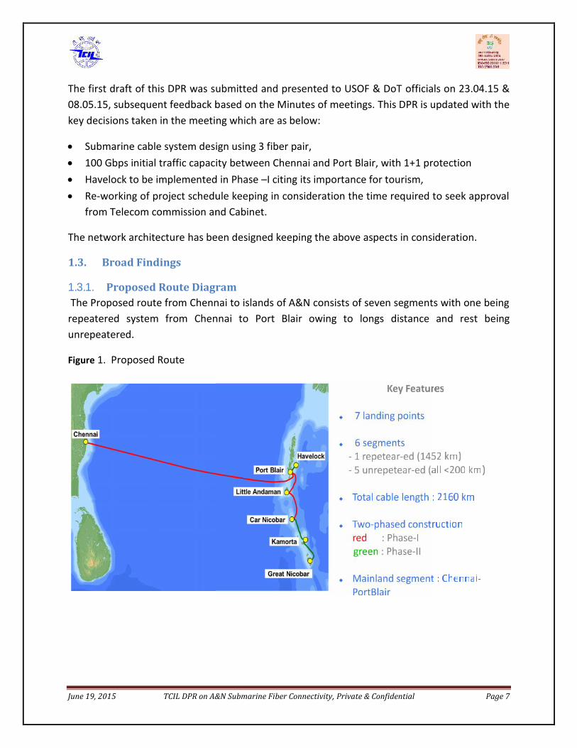
1.3. Broad Findings1.3.1. Proposed Route DiagramThe Proposed route from Chennai to islands of A&N consists of seven segments with one being
repeatered system from Chennai to Port Blair owing to longs distance and rest beingunrepeatered.
Figure 1. Proposed Route
June 19, 2015 TCIL DPR on A&N Submarine Fiber Connectivity, Private & Confidential Page 7
The first draft of this DPR was submitted and presented to USOF & DoT officials on 23.04.15 &08.05.15, subsequent feedback based on the Minutes of meetings. This DPR is updated with thekey decisions taken in the meeting which are as below:
Submarine cable system design using 3 fiber pair, 100 Gbps initial traffic capacity between Chennai and Port Blair, with 1+1 protection Havelock to be implemented in Phase –I citing its importance for tourism, Re-working of project schedule keeping in consideration the time required to seek approval
from Telecom commission and Cabinet.
The network architecture has been designed keeping the above aspects in consideration.
1.3. Broad Findings1.3.1. Proposed Route DiagramThe Proposed route from Chennai to islands of A&N consists of seven segments with one being
repeatered system from Chennai to Port Blair owing to longs distance and rest beingunrepeatered.
Figure 1. Proposed Route

June 19, 2015 TCIL DPR on A&N Submarine Fiber Connectivity, Private & Confidential Page 8
1.3.2. Route Length
The summary of Route length and corresponding cable length for various segments fromChennai to A&N islands is
Table 1: Route Length & Cable Length
SEGMENTROUTE
LENGTH(KM)
CABLELENGTH
(KM)
Seg 1 Chennai to Port Blair 1424.57 1452.08
Seg 2 Port Blair to Little Andaman 138.18 141.36
Seg 3 Little Andaman to Car Nicobar 186.11 191.65
Seg 4 Car Nicobar to Kamorta (Western Route) 181.79 186.37
Seg 5 Kamorta to Great Nicobar (Western Route) 142.10 146.32
Seg 6 Port Blair to Havelock Island 45.97 46.43
Total 2118.73 2164.23
1.3.3. System DimensioningIn the approach paper, the 10Gbps bandwidth requirement was assessed in A&N islands in
year 2020. And during the planning commission meeting it was pointed out that the bandwidthestimation is on a conservative side. TRAI recommendations on A&N islands(dated July 2014)has also estimated a bandwidth of 55 Gbps following percentage penetration as per NationalBroadband Plan.
Therefore, while floating the tender for DTS vendor selection to further estimate the cost it wasenvisaged to have a submarine cable system working on 10Gbps per lambda with total designcapacity of 64 X 10 Gbps i.e. the SLTE would be of 640 Gbps capacity comprising of 64wavelengths @ 10Gbps.
However, the DTS vendor informed TCIL that now the OEM’s are manufacturing 100Gbpssystems i.e. 100Gbps per lambda and 10 Gbps system are no longer being installed in newinstallations.
June 19, 2015 TCIL DPR on A&N Submarine Fiber Connectivity, Private & Confidential Page 9
Courtesy: NEC
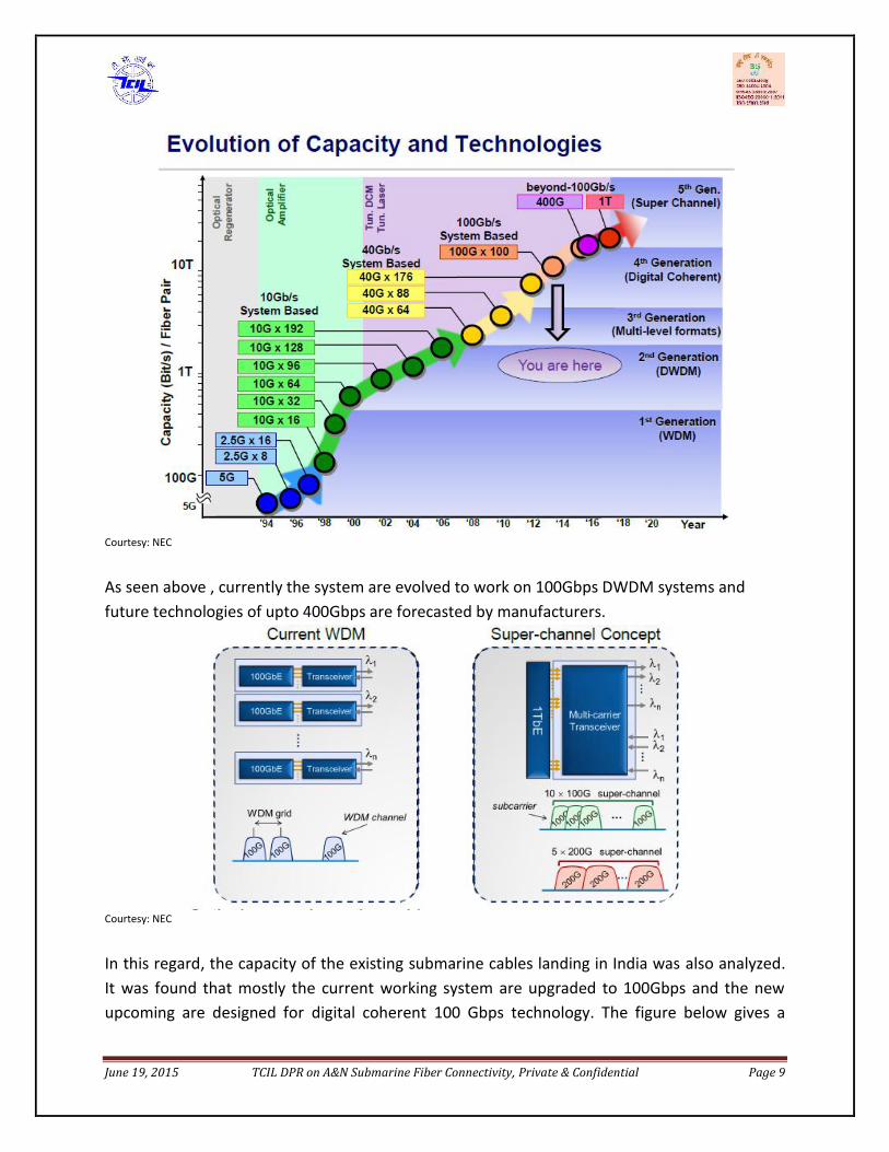
As seen above , currently the system are evolved to work on 100Gbps DWDM systems andfuture technologies of upto 400Gbps are forecasted by manufacturers.
Courtesy: NEC
In this regard, the capacity of the existing submarine cables landing in India was also analyzed.It was found that mostly the current working system are upgraded to 100Gbps and the newupcoming are designed for digital coherent 100 Gbps technology. The figure below gives a
June 19, 2015 TCIL DPR on A&N Submarine Fiber Connectivity, Private & Confidential Page 9
Courtesy: NEC
As seen above , currently the system are evolved to work on 100Gbps DWDM systems andfuture technologies of upto 400Gbps are forecasted by manufacturers.
Courtesy: NEC
In this regard, the capacity of the existing submarine cables landing in India was also analyzed.It was found that mostly the current working system are upgraded to 100Gbps and the newupcoming are designed for digital coherent 100 Gbps technology. The figure below gives a

June 19, 2015 TCIL DPR on A&N Submarine Fiber Connectivity, Private & Confidential Page 10
snapshot of cable landing in India, Indian Telecom owners, associated technology upgrade andfiber pair.
Figure 2: Cable systems landing in India since 2005 and the technologySrNo
CableSystem
Year ofcommissioning
1st
Upgrade2nd
Upgrade3rd
Upgrade4th
upgradeOwners(nos.)
IndianTelcos
No. offiberpair
1 SMW4 2005 2007 2009 2012 2014 17 Tata Comm.,Airtel
2(10G) (10G) (10G) (40G) (100G)
2 SEACOM 2009 2013 - - - 6 Tata 4(10G) (40G)
3 I-ME-WE 2010 2012 2015(expected)
9 Tata Comm.,Airtel
3
(10G) (40G) (100G)4 EIG 2011 2013 2015
(expected)- - 14 Airtel, BSNL,
Vodafone3
(10G) (100G) 100G5 GBI 2012 2015 - - - 2 2
(expected)(10G) (100G)
6 BBG 2015 - - - - 7 Vodafone ,reliance
3(expected)
(100G)7 SMW5 2016 - - - - 14 3
(expected)
(100G)8 AAE-1 2016 - - - - 12 5
(expected)
(100G)9 i2i 2002 1 Airtel 8
(105X10 Gbps)
As the advancement in digital coherent DWDM technology and the transmission optical fiber ,the adoption of 100Gbps DWDM in submarine networks significantly increases fiber capacity ina cost effective way. Hence, it was felt appropriate to go for a 64 X 100Gbps (6.4 Tbps) systemdesign. To start with, a fiber will carry a single wavelength @ 100Gbps in 1+1 protection i.e. oneSLTE per fiber and two fibers will be lit with each 100Gbps lambda capacity.
June 19, 2015 TCIL DPR on A&N Submarine Fiber Connectivity, Private & Confidential Page 11
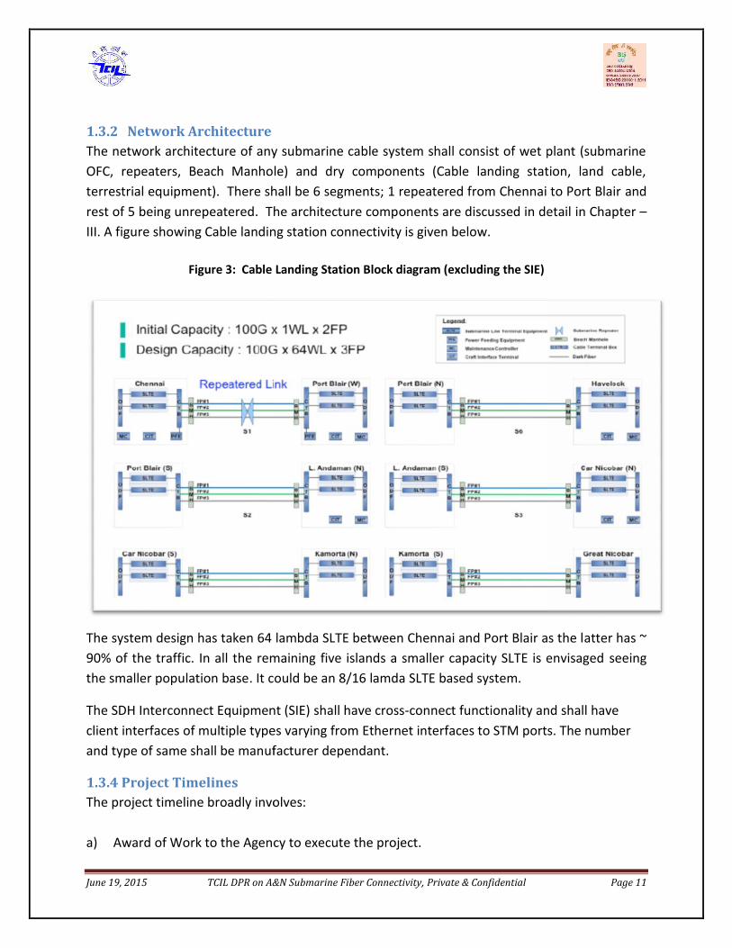
1.3.2 Network ArchitectureThe network architecture of any submarine cable system shall consist of wet plant (submarineOFC, repeaters, Beach Manhole) and dry components (Cable landing station, land cable,terrestrial equipment). There shall be 6 segments; 1 repeatered from Chennai to Port Blair andrest of 5 being unrepeatered. The architecture components are discussed in detail in Chapter –III. A figure showing Cable landing station connectivity is given below.
Figure 3: Cable Landing Station Block diagram (excluding the SIE)
The system design has taken 64 lambda SLTE between Chennai and Port Blair as the latter has ~90% of the traffic. In all the remaining five islands a smaller capacity SLTE is envisaged seeingthe smaller population base. It could be an 8/16 lamda SLTE based system.
The SDH Interconnect Equipment (SIE) shall have cross-connect functionality and shall haveclient interfaces of multiple types varying from Ethernet interfaces to STM ports. The numberand type of same shall be manufacturer dependant.
1.3.4 Project TimelinesThe project timeline broadly involves:
a) Award of Work to the Agency to execute the project.
June 19, 2015 TCIL DPR on A&N Submarine Fiber Connectivity, Private & Confidential Page 11
1.3.2 Network ArchitectureThe network architecture of any submarine cable system shall consist of wet plant (submarineOFC, repeaters, Beach Manhole) and dry components (Cable landing station, land cable,terrestrial equipment). There shall be 6 segments; 1 repeatered from Chennai to Port Blair andrest of 5 being unrepeatered. The architecture components are discussed in detail in Chapter –III. A figure showing Cable landing station connectivity is given below.
Figure 3: Cable Landing Station Block diagram (excluding the SIE)
The system design has taken 64 lambda SLTE between Chennai and Port Blair as the latter has ~90% of the traffic. In all the remaining five islands a smaller capacity SLTE is envisaged seeingthe smaller population base. It could be an 8/16 lamda SLTE based system.
The SDH Interconnect Equipment (SIE) shall have cross-connect functionality and shall haveclient interfaces of multiple types varying from Ethernet interfaces to STM ports. The numberand type of same shall be manufacturer dependant.
1.3.4 Project TimelinesThe project timeline broadly involves:
a) Award of Work to the Agency to execute the project.
June 19, 2015 TCIL DPR on A&N Submarine Fiber Connectivity, Private & Confidential Page 12
This involves DPR approval from Telecom Commission and Cabinet, Tender preparation forselection of agency fori) submarine projectii) Permit in Principle , EIA (Environmental Impact Assessment) & CRZ (Coastal Region Zone)
clearance required as a permit in this projectiii) Civil infrastructure readinessiv) Project Management of this project.
As per the latest minutes of meeting, the USF plan to take the cabinet approval by December2015, and therefore the time envisaged under this category 10-12 months after Cabinetapproval.
b) Execution of this project.The project shall be awarded to a specialized agency for supply and service of this project. Anysubmarine cable laying projects broadly involves following activities: Marine Survey Submarine Cable Manufacturing Repeater Manufacturing Loading & Transit Custom Clearance Marine Installation Land Cable Manufacturing RoW for Land Cable Route Land Cable Installation Submarine Equipment Installation at CLS Acceptance Testing & System commissioning (Go Live)
Each activity has a different duration but may get executed in parallel. The time gauged toexecute the project shall be 24 Months from the date of award of project. It is to mention thatthis is subject to award of work date as the suitable months for laying the submarine cable asindicated by DTS vendor are from November to April depending on the monsoon conditions.
1.3.5 Project Cost EstimateBased on the system design assumptions as stated above, the cost of capital and operationalexpenditure in rolling the project is estimated. Budgetary quotes were obtained from threeleading submarine manufacturing OEM’s and self-assessment based on submarine surveyresults by the DTS vendor. The summary table is as given below:

June 19, 2015 TCIL DPR on A&N Submarine Fiber Connectivity, Private & Confidential Page 13
Table 2: CAPEX EstimateS.No. Item Heads Cost (in USD Mn.)
Phase -ICost (in Rs. cr.)Phase-I
1. Submarine System 72.7 458.012. Taxies & Duties 14.2 89.463. Other CAPEX elements 5.0 31.5
Sub-Total 91.9 578.974. Contingency@2% 1.8 11.34
Total 93.8 590.945. Project Management Cost@10% 9.38 59.094
TOTAL 103.18 650.034Note: The highest budgetary quote has been taken for approval purpose. The quotes given by othervendors are detailed in subsequent chapters.
1.3. Project SensitivitiesThe various critical activities in this project may hamper the Project Schedule like Delay in obtaining environmental and regulatory clearances and other permits. Delay in award of work may affect the overall project schedule as the weather
conditions favorable for Submarine Cable Laying is December to April. Availability of Buildings for Cable landing station and its Readiness. Local Clearances for Beach Manhole construction and RoW for land cable. Natural Calamity.
1.4. RecommendationsThe recommendations are as below:
I. Initial system capacity of 100 Gbps per lambda is recommended as that is the currenttechnology being offered by OEM’s. Hence overall system design capacity of 6.4 Tbps(64 X 100 Gbps) is recommended.
II. It is recommended to go for three fiber pair from national and strategic perspective.
1.5. Structure of the ReportChapter –II Covers the general introduction including present scenario of A&N, telecom need,
the solution and about submarine cable system.
Chapter –III The details of project of connecting A&N is covered with network architecture, keydesign parameters, alternate media connectivity with Port Blair.
Chapter-IV Covers the project cost of submarine connectivity.
Chapter –V Details the execution methodology and timeline of the project.

June 19, 2015 TCIL DPR on A&N Submarine Fiber Connectivity, Private & Confidential Page 14
Chapter- VI covers the Permits & Licenses required in this project along with the time frame.
Chapter – VII details the Risks & Hazards perceived in this project.
Chapter –VIII details the PMC services, ownership & commercial issues, Way forward.
June 19, 2015 TCIL DPR on A&N Submarine Fiber Connectivity, Private & Confidential Page 15
2. INTRODUCTION
2.1. About Andaman & Nicobar IslandsAndaman and Nicobar (ANI) group of islands is situated in the eastern bank of Indian Territorycentered with international transoceanic activities of southeastern countries. Port Blair, thecapital of the union Territory is situated 1255 and 1190 kms from Kolkata and Chennairespectively.
Andaman & Nicobar comprises of over 572 islands, of which 37 islands are inhabited with apopulation more than 80% lives in Andaman’s (North, Middle and South). The populationdetails of the islands as per census of India are provided. It is seen that that islands under CarNicobar district is showing a decrease in the population growth rate.
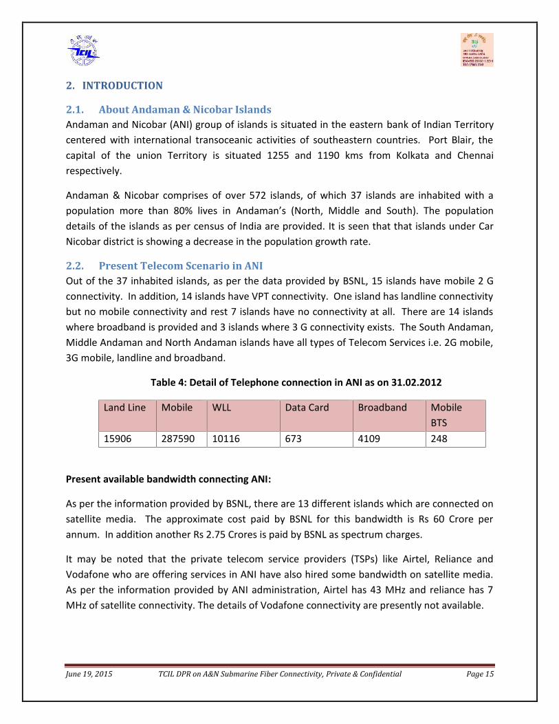
2.2. Present Telecom Scenario in ANIOut of the 37 inhabited islands, as per the data provided by BSNL, 15 islands have mobile 2 Gconnectivity. In addition, 14 islands have VPT connectivity. One island has landline connectivitybut no mobile connectivity and rest 7 islands have no connectivity at all. There are 14 islandswhere broadband is provided and 3 islands where 3 G connectivity exists. The South Andaman,Middle Andaman and North Andaman islands have all types of Telecom Services i.e. 2G mobile,3G mobile, landline and broadband.
Table 4: Detail of Telephone connection in ANI as on 31.02.2012
Land Line Mobile WLL Data Card Broadband MobileBTS
15906 287590 10116 673 4109 248
Present available bandwidth connecting ANI:
As per the information provided by BSNL, there are 13 different islands which are connected onsatellite media. The approximate cost paid by BSNL for this bandwidth is Rs 60 Crore perannum. In addition another Rs 2.75 Crores is paid by BSNL as spectrum charges.
It may be noted that the private telecom service providers (TSPs) like Airtel, Reliance andVodafone who are offering services in ANI have also hired some bandwidth on satellite media.As per the information provided by ANI administration, Airtel has 43 MHz and reliance has 7MHz of satellite connectivity. The details of Vodafone connectivity are presently not available.
June 19, 2015 TCIL DPR on A&N Submarine Fiber Connectivity, Private & Confidential Page 15
2. INTRODUCTION
2.1. About Andaman & Nicobar IslandsAndaman and Nicobar (ANI) group of islands is situated in the eastern bank of Indian Territorycentered with international transoceanic activities of southeastern countries. Port Blair, thecapital of the union Territory is situated 1255 and 1190 kms from Kolkata and Chennairespectively.
Andaman & Nicobar comprises of over 572 islands, of which 37 islands are inhabited with apopulation more than 80% lives in Andaman’s (North, Middle and South). The populationdetails of the islands as per census of India are provided. It is seen that that islands under CarNicobar district is showing a decrease in the population growth rate.
2.2. Present Telecom Scenario in ANIOut of the 37 inhabited islands, as per the data provided by BSNL, 15 islands have mobile 2 Gconnectivity. In addition, 14 islands have VPT connectivity. One island has landline connectivitybut no mobile connectivity and rest 7 islands have no connectivity at all. There are 14 islandswhere broadband is provided and 3 islands where 3 G connectivity exists. The South Andaman,Middle Andaman and North Andaman islands have all types of Telecom Services i.e. 2G mobile,3G mobile, landline and broadband.
Table 4: Detail of Telephone connection in ANI as on 31.02.2012
Land Line Mobile WLL Data Card Broadband MobileBTS
15906 287590 10116 673 4109 248
Present available bandwidth connecting ANI:
As per the information provided by BSNL, there are 13 different islands which are connected onsatellite media. The approximate cost paid by BSNL for this bandwidth is Rs 60 Crore perannum. In addition another Rs 2.75 Crores is paid by BSNL as spectrum charges.
It may be noted that the private telecom service providers (TSPs) like Airtel, Reliance andVodafone who are offering services in ANI have also hired some bandwidth on satellite media.As per the information provided by ANI administration, Airtel has 43 MHz and reliance has 7MHz of satellite connectivity. The details of Vodafone connectivity are presently not available.

June 19, 2015 TCIL DPR on A&N Submarine Fiber Connectivity, Private & Confidential Page 16
2.3. Issues with Present Telecom Connectivity in ANIThe existing telecom connectivity to ANI is on satellite media which has its own limitations. Thebandwidth available through satellite is limited and very costly. The population of most islandsis very less and there is no business case for telecom service providers. For this reason most ofthe private service providers are not offering their services in ANI. In case a private telecomservice provider is offering service, it is confined to couple of big islands only. Presently, theentire connectivity to ANI is dependent on satellite media and there is no other alternate mediaavailable for restoring communication links in case of any natural calamity/disaster. Limitedavailability of bandwidth due to satellite foot print coverage and limited number oftransponders pose a serious problem in bandwidth enhancement. Lack of bandwidth andtelecom connectivity causes difficulty in implementing e – Governance initiatives and providingadequate support to educational institutes for knowledge sharing. It is also seriouslyhampering the ability of ANI to attract IT/ITeS players for establishing enterprises and e –Commerce facilities and impacting the job opportunities available.
In absence of bandwidth, in most of the island the telecom services are provided only by BSNL.Absence of alternate service provider causes a serious problem in case BSNL network is down.Connectivity crunch causes further difficulty in disaster management and relief activities.
As the telecom services will expand in future and more residents will demand broadbandservices, it is expected that requirement of bandwidth will increase exponentially. It will bedifficult and extremely costly to provide such a large bandwidth on satellite. Further,procurement of bandwidth from foreign satellites will require foreign exchange and can beavoided. Thus, the media for Port Blair and other islands needs to be upgraded to take care ofthe growth of mobile as well as broadband services.
In view of above, there is an urgent requirement to provide alternate media to ANI through andundersea cable.
2.4. Future Bandwidth Requirements of ANIPresent telecom connectivity provided through satellite to A&N islands is limited and does notprovide sufficient bandwidth for various applications. The submarine fiber cable shall provide areliable and unlimited bandwidth to A&N islands. It is required to assess the future bandwidthof A&N islands to design the submarine system cable.
TCIL’s Bandwidth Assessment
The future bandwidth requirements have been assessed of all the inhabited islands of ANI. Toassess the need of submarine in islands of Andaman & Nicobar, a detailed bandwidth
June 19, 2015 TCIL DPR on A&N Submarine Fiber Connectivity, Private & Confidential Page 17
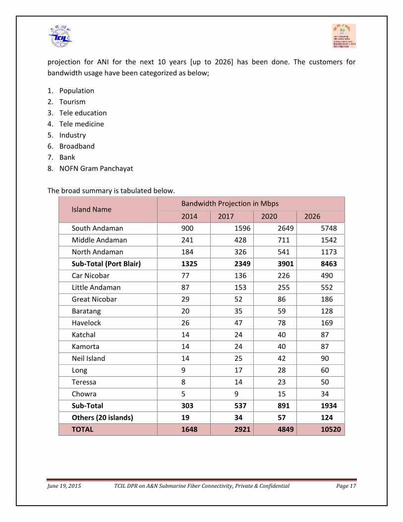
projection for ANI for the next 10 years [up to 2026] has been done. The customers forbandwidth usage have been categorized as below;
1. Population2. Tourism3. Tele education4. Tele medicine5. Industry6. Broadband7. Bank8. NOFN Gram Panchayat
The broad summary is tabulated below.
Island NameBandwidth Projection in Mbps
2014 2017 2020 2026South Andaman 900 1596 2649 5748Middle Andaman 241 428 711 1542North Andaman 184 326 541 1173Sub-Total (Port Blair) 1325 2349 3901 8463Car Nicobar 77 136 226 490Little Andaman 87 153 255 552Great Nicobar 29 52 86 186Baratang 20 35 59 128Havelock 26 47 78 169Katchal 14 24 40 87Kamorta 14 24 40 87Neil Island 14 25 42 90Long 9 17 28 60Teressa 8 14 23 50Chowra 5 9 15 34Sub-Total 303 537 891 1934Others (20 islands) 19 34 57 124TOTAL 1648 2921 4849 10520
June 19, 2015 TCIL DPR on A&N Submarine Fiber Connectivity, Private & Confidential Page 17
projection for ANI for the next 10 years [up to 2026] has been done. The customers forbandwidth usage have been categorized as below;
1. Population2. Tourism3. Tele education4. Tele medicine5. Industry6. Broadband7. Bank8. NOFN Gram Panchayat
The broad summary is tabulated below.
Island NameBandwidth Projection in Mbps
2014 2017 2020 2026South Andaman 900 1596 2649 5748Middle Andaman 241 428 711 1542North Andaman 184 326 541 1173Sub-Total (Port Blair) 1325 2349 3901 8463Car Nicobar 77 136 226 490Little Andaman 87 153 255 552Great Nicobar 29 52 86 186Baratang 20 35 59 128Havelock 26 47 78 169Katchal 14 24 40 87Kamorta 14 24 40 87Neil Island 14 25 42 90Long 9 17 28 60Teressa 8 14 23 50Chowra 5 9 15 34Sub-Total 303 537 891 1934Others (20 islands) 19 34 57 124TOTAL 1648 2921 4849 10520

June 19, 2015 TCIL DPR on A&N Submarine Fiber Connectivity, Private & Confidential Page 18
Assumptions for Bandwidth Projection:
1. A 50 mErlang traffic per subscriber is taken for subscriber’s traffic from ANI population and touristsin later years. It is assumed that this will include the traffic generated by wireless internetsubscribers.
2. A 2Mbps bandwidth is provided in each category. However a contention ratio of 1:30 is applied onindustrial, hospital, bank & broadband customers, the current TRAI guidelines define a contentionratio of 1:50 and 1:30 on broadband connections for residential and industrial purposesrespectively.
3. In the projections, the Gram Panchayat and educational institutions have been provided 2Mbpsbandwidth as per the BBNL mandate and video streaming required for tele-education traffic.
4. To calculate the per island traffic, the total Mbps so arrived through various categories has beendistributed in the ratio of population of the islands.
The key observations areas below;
1. It is seen from the above table that the maximum bandwidth requirement would reach 10Gbps in 10years i.e by 2026
2. The requirements for Andaman and Little Andaman in 2018 year will be 2.9 Gbps and by 2026 year itwould be 9.0Gbps. This would make satellite connectivity unfeasible. OFC can be only option forsuch bandwidth requirements.
3. Considering that the 90% population is in Andaman (North, Middle, and South) and a terrestrial OFCnetwork already exists there it would be optimal that fiber connectivity be given from Port Blair toChennai.TRAI’s Bandwidth Assessment
TRAI has issued recommendation in telecom connectivity in A& N and Lakhshadweep islandsdated 22/07/14. The methodology in TRAI recommendations to assess the future requirementof bandwidth is based on the projections for phase-I, made in the Authority’s earlierrecommendations on “National Broadband Plan” dated 8th December 2010, i.e. availability of 2Mbps bandwidth per household with projected penetration of 12%, 39% and 64% in villages,towns and cities respectively with a contention ratio of 1:10, estimated backhaul requirementfor these islands has been worked out as given in Table below.

June 19, 2015 TCIL DPR on A&N Submarine Fiber Connectivity, Private & Confidential Page 19
The figures indicate that bandwidth requirements are high in north, Middle and SouthAndaman Islands which have 80% population followed by Little Andaman, Car Nicobar and therest of the scattered islands with low population figures can be provided telecom connectivitythrough Satellite.
June 19, 2015 TCIL DPR on A&N Submarine Fiber Connectivity, Private & Confidential Page 20
The bandwidth assessment done by TCIL seems to be on the conservative side and seeing thebandwidth projected per gram panchayat (GP) under NOFN project @100Mbps, the TRAIestimate of 55 Gbps requirement looks more realistic.
2.5. Need of Reliable Telecom ConnectivityEconomy of the country and ICT has a recursive relationship. They help each other grow. Areliable and expandable network with robust connectivity is the most important key todevelopment of a region; be it road, rail, waterway, air, power or telecom. Connectivity ensuresthat an otherwise distant region is part and parcel of the mainland. It helps in overall economicdevelopment and social integration of the region. Robust telecom and broadband connectivityand provision of quality telecom services is an avowed national priority. Hence, delivering suchquality services and connectivity to the Andaman & Nicobar Islands is an integral component ofrealizing the national objective.
As per the discussions above, it is clear that the ANI has increasing bandwidth requirementwhich cannot be met by present satellite connectivity. From the disaster management point ofview also it is essential to connect ANI with the mainland in India using a wired media ofundersea optical fiber.
2.6. Submarine Optical Fiber Communication SystemSubmarine cables are laid on the sea bed between land-based stations to carrytelecommunication signals. They offer highly secure, greatly reliable and very high capacitytelecommunication links between countries across the world. The transmission quality of a sub-marine cable is significantly better than a typical satellite media. Submarine cables are only afew inches thick and they carry only a few optical fibers. Yet they have transmission capacitiesof the order of terra bits per second (Tbps). However, a typical multi-terabit, trans-oceanicsubmarine cable system costs several hundred million dollars to construct.
A typical submarine cable system consists of (i) a submarine cable in the sea-bed and (ii) cablelanding stations at lands.
Cable Landing Station is one important component of a submarine cable system whichcomprises of Wet Plant and Dry Plant. The Dry Plant of a submarine cable system is a segmentbetween the beach manhole and the cable landing station, comprises of land cable, powerfeeding equipment (PFE) and submarine line terminal equipment (SLTE), etc. The Wet Plant ofa submarine cable system lies between the beach manholes, consists of submarine cable,repeater/gain equalizer, branching unit. A typical schematic of a submarine cable system isshown below

June 19, 2015 TCIL DPR on A&N Submarine Fiber Connectivity, Private & Confidential Page 21
The submerged plant considered comprise of the cable for transmission, repeaters to amplifythe signal at regular intervals, equalizers to maintain equal power in each signal channel, andbranching units to enable network connectivity and flexibility. Associated with the submergedequipment is power-feed equipment, which is located at the terminal stations.
The operating environment of the submerged plant places great demands on its mechanicaldesign. In addition to requirement for mechanical strength against external water pressure, theequipment housing must protect the interior atmosphere against gas ingress. The target for thereliability of the submarine plant is that no more than one ship repair should be needed duringthat lifetime per two fiber pairs on a transatlantic cable. Such high reliability is ensured bydesign, with the use of high-reliability electronics and application of redundancy forcomponents that display higher failure rates, together with strict quality procedures in theselection, testing, bum-in, and documentation of components and the use of ultracleanfabrication facilities.2.6.1. Wet Plant ComponentsThe highly-flexible submarine optical transmission system, capable of supporting data rates up
to Tera Bytes per fiber-pair. Its primary elements include the submersible Repeaters (REP),submarine Branching Units (BU) and undersea Passive Equalization Units (PEU).
a) CablesThe cable has the primary objective to protect the fibers from the external worldand to provide a means to connect the terminal stations through the wet-plantequipment. The cable is also in charge of carrying the power to the submergedequipment. The design of modem optical submarine repeatered cablesconcentrates on providing a stable low-loss optical transmission path, a power-

June 19, 2015 TCIL DPR on A&N Submarine Fiber Connectivity, Private & Confidential Page 22
feeding conductor for the submerged amplifiers, and sufficient strength and robustnessto facilitate safe and successful installation operation and, if necessary, repair. The keyfiber attribute in many wavelength-division multiplexing transmission systems is theattenuation of the optical fiber, which determines the amplifier or repeater spacing andis a key consideration in system design and cost.The Submarine optical fiber cable is laid connecting the terminal nodes between fromthe beach manhole of one node at the shore end on the sea bed. There are varioustypes of submarine fiber cables depending on the protection layer provided on them.
i. Type of armor
• Armor wire (LWA, SA, DA, RA, etc.)• Metallic screen/strengthen jacket (LWP, LWS, SPA, etc.)• Armoring post cable manufacturing• Duct, articulated pipe, etc.
ii. The type of fiber to be laid varies with the depth of the seabed. Factors of armorselection:
• water depth for a cable recovery• threat and hazard• what burial possible
burial depth (level of requirement and achievement) burial method, tool soil condition
Generally near the shore, armored cable is led to protect from the fiber cut because of humanactivities and non –armored is led on the sea-bed where the depth is high and surface is even.
b) Repeaters
The highly-reliable submarine repeaters provide
amplification of the full 128-WDM optical wave band,
using wideband flat gain optical amplifiers. Being
amplifiers, the repeaters do not restrict the transmission rate to a particular value,
thereby offering complete system flexibility.

June 19, 2015 TCIL DPR on A&N Submarine Fiber Connectivity, Private & Confidential Page 23
c) Branching Units
Submersible branching units (BU) interconnects threecable segments and provides the optical fiber forapplicable configurations and power interconnection.
d) Passive Equalizer Units (PEU)Passive Equalizer Units (PEU) are inserted in a submarine optical fiber cable to equalizethe wavelength-dependent loss across the DWDM waveband, thereby improving thequality of transmission across a long cable. The gain equalization process is purelypassive, using separate passive optical devices for each fiber.
2.6.2. Dry Plant Components
SLTE: Submarine Line Terminating EquipmentLTU: Line Terminating UnitWTU: Wavelength Terminating Unit
RLTU: Redundant LineTerminating Unit(optional)
MC:MC: MaintenanceController
CIT: Craft Interface Terminal
A complete and highly-flexible submarine optical transmission system capable of supportingdata rates from Gigabits/sec to Terabits/sec per fiber-pair. Its primary elements include theCable Landing Station (CLS), Line Terminating Units (LTU), the Wavelength Terminating Units(WTU) and the Maintenance Controller (MC).

June 19, 2015 TCIL DPR on A&N Submarine Fiber Connectivity, Private & Confidential Page 24
A submarine cable system consists of a communication cable laid on the seabed between cablelanding stations (CLS) on the land to carry telecommunication signals across stretches of ocean.The CLS is a building containing the onshore end of the submarine cable and equipment forconnecting to backhaul circuits.2.6.3. Marine Operations and MaintenanceSubmarine cable systems are designed for robustness and reliability during a 25-year lifespan.However, there is always the risk of damage from external sources. To help reduce the impactof cable outages, a periodical regular submarine cable maintenance services is required.
The ships and depots are strategically positioned so that they can arrive at a problem locationas quickly as possible, equipped to perform any repairs.
Special fleet ships are manned by qualified, experienced teams and are strategically located tolay the fiber and maintain it. The cable ships are equipped with High engine power, thrustersand dynamic positioning to maintain position and work in almost any weather conditions, High-tow force, heavy-duty ploughs for cable burial, Cable lay control systems. A Remotely OperatedVehicle (ROV) is used for installation and maintenance. World wide these submarine cables aremaintained by this special fleet ships and their regions are divided as shown in map below.
2.7. Approach of Connectivity on Submarine Fiber to ANIThe submarine connectivity to ANI may be provided either by appending a spur from theexisting submarine cable of telecom operators crossing ten degree channel or by laying adedicated cable from mainland India to Port Blair.
June 19, 2015 TCIL DPR on A&N Submarine Fiber Connectivity, Private & Confidential Page 25
The cost benefit analysis of both the above mentioned options has been made in the Approachpaper submitted earlier by TCIL. The cost of laying fiber from the existing cable was calculatedfrom the two existing cables of Tata, and Airtel and one upcoming cable of BBG laid by aconsortium made between Indian and foreign telcos covering many continents. It wasobserved that though the cost incurred in laying and maintaining dedicated cable is more butthe other benefits of laying the dedicated cable outweigh the incremental cost differencebetween the two approaches.
With the dedicated submarine cable all the requirements of ANI shall be met, along with theDefense requirements for their NFS project which can be given a separate dedicated fiber. Byusing the existing cable, the issue of residual life (taken as 25 years theoretically) shall remain,as no existing cable has residual life of more than 15 years left. BBG has declared of not havingany spare fiber for connectivity to Port Blair.
By establishing submarine connectivity to Port Blair itself shall cover approximately 80%population of A&N Islands. If as per plan the Little Andaman & Car Nicobar is also connectedthen 90% population of A&N Islands shall get covered.
The ownership of dedicated fiber shall be taken by a single party and in future depending onthe bandwidth requirements; the undersea cable can be extended to other islands from CarNicobar i.e. Kamorta, Havelock and Great Nicobar.
All these aspects analyzed in the Approach paper had been discussed in various meetings withDoT and a planning commission meeting as well. It was concluded to lay dedicated optical fibercable from Chennai to Port Blair.
The first draft of this DPR was submitted and presented to USOF & DoT officials on 23.04.15 &08.05.15, subsequent feedback based on the Minutes of meetings. This DPR is updated with thekey decisions taken in the meeting which are as below:
Submarine cable system design using 3 fiber pair, 100 Gbps initial traffic capacity between Chennai and Port Blair, with 1+1 protection Havelock to be implemented in Phase –I citing its importance for tourism, Re-working of project schedule keeping in consideration the time required to seek approval
from Telecom commission and Cabinet.
June 19, 2015 TCIL DPR on A&N Submarine Fiber Connectivity, Private & Confidential Page 26
3. DEDICATED SUBMARINE OPTICAL FIBER CABLE TO ANI
3.1. Project OverviewThe A& N islands shall be connected with dedicated submarine fiber cable from mainland Indiaat Chennai. The implementation shall be done in two phases. In the first phase submarineoptical fiber shall be laid from Chennai to Port Blair which would then be extended to LittleAndaman & Car Nicobar and from Port Blair to Havelock. In the second phase Kamorta & GreatNicobar shall be connected.
There are broadly two type of submarine connectivity: Repeatered and Un-repeatered.Repeater less submarine cable systems are used for terrestrial network extensions in cases
where submarine distances up to about 350 km are to be covered. Repeatered submarinesystems are used for long haul, large capacity transmission by using submerged opticalamplifiers in order to cross distances up to transoceanic lengths.
The approximate distance from Chennai to Port Blair is 1450 kms. Therefore the submarinecommunication network to be implemented shall be repeatered. However further from PortBlair to other islands as the distance is less than 200km, the un-repeatered submarineconnectivity shall be planned.

June 19, 2015 TCIL DPR on A&N Submarine Fiber Connectivity, Private & Confidential Page 27
3.1.1. Network Communication Architecture
3.1.1.1. Submarine Connectivity
15
Architecture- ANI Cable system
Key Features
7 landing points
6 segments- 1 repeat red (1452 km)- 5 un-repeaterd (all <200 km)
Total cable length : 2160 km Two-phased construction
red : Phase-Igreen : Phase-II
Mainland segment : Chennai-
Port Blair
3.1.1.2. Overall Equipment SchematicEach site in a submarine cable system consists of terrestrial equipment on cable landing stationand submarine optical fiber cable terminating at the beach man hole on the site.
Phase I (Port Blair, Little Andaman, Car Nicobar, Havelock)Phase II (Kamorta, Great Nicobar)

June 19, 2015 TCIL DPR on A&N Submarine Fiber Connectivity, Private & Confidential Page 28
3.1.1.3. System configurationThe system shall consist of whole Submarine Plant, land Cable and Terminal Station equipmentsincluding the SDH Interconnect Equipment (SIE) up to the interfaces at the Terminal stations.The submarine connectivity from mainland India to A&N islands has various segments as shownin the diagram above. Each segment includes the land cable and the submerged plantcontaining optical fiber pair including the terminal station equipment facing the segment cableat Cable landing station (LTE & SIE, SDH/DWDM). A generic diagram showing variouscomponents is given below:

June 19, 2015 TCIL DPR on A&N Submarine Fiber Connectivity, Private & Confidential Page 29
3.1.2. Design Considerations
3.1.2.1. Dry PlantThe system proposed will be based on the latest technology of dense wavelength division multiplexing(DWDM) with the following characteristics:
Proposed terminal equipment shall provide:o High traffic availability throughout redundancy of key components.o Large capacity in a compact size.o High performance with advanced line interfaceso Software configurable client interfaces supporting various services.o User friendly maintenance controller (MC) dedicated to the repeatered segment
and network management system (NMS) for the repeatered less segment.o A data communication network (DCN) featuring protection against wavelength
failure and cable break.
3.1.2.1.1. Cable Landing Station (CLS)The CLS is a building containing the onshore end of the submarine cable and equipment forconnecting to backhaul circuits.
i. Consideration of Cable Landing Station: Floor space for terminal equipment, facilities and office for maintenance staff, etc Connectivity to back haul network Access for construction and future maintenance

June 19, 2015 TCIL DPR on A&N Submarine Fiber Connectivity, Private & Confidential Page 30
Approach to the cable landing site Land cable route Electronic/magnetic interference
ii. Suitable for cable landing/installation operation Cable laying ship can easily access to the beach Access for beach works and usage of heavy machinery Seabed topography, material and condition Close parallels/crossing to other cables, pipelines Low risk of fishing activity, anchoring, dredging, mining Regulation, permission issues National park, coastal reserves, etc
There can be more than one prospective Cable landing station sites considering the abovefactors.
The selected DTS vendor carried out the site visits from 9th March to 19th March 2015 whereinall the subject islands were visited to assess the position of potential CLS & BMH locations.Meetings were also carried out with relevant authorities like ANI administration, PWD and BSNLofficials
For the cable landings stations as discussed in various meetings with DoT the existing BSNLexchanges in proximity with the beaches where submarine cable shall be terminated wassurveyed. However, the locations identified may change subject to the confirmation by localauthorities.
The site visit of the six islands was taken up by DTS agency M/s OSS and depending on theinteraction with the ANI administration, the presence of existing telecom infrastructure ofBSNL, various sites were identified as prospective CLS sites. The details of the site visit alongwith pictures of identified locations are given in the report by M/s OSS (Part – I). As a sample apicture of potential CLs identified in Port Blair, a BSNL Telephone Exchange Building (Abardeen)is placed below.
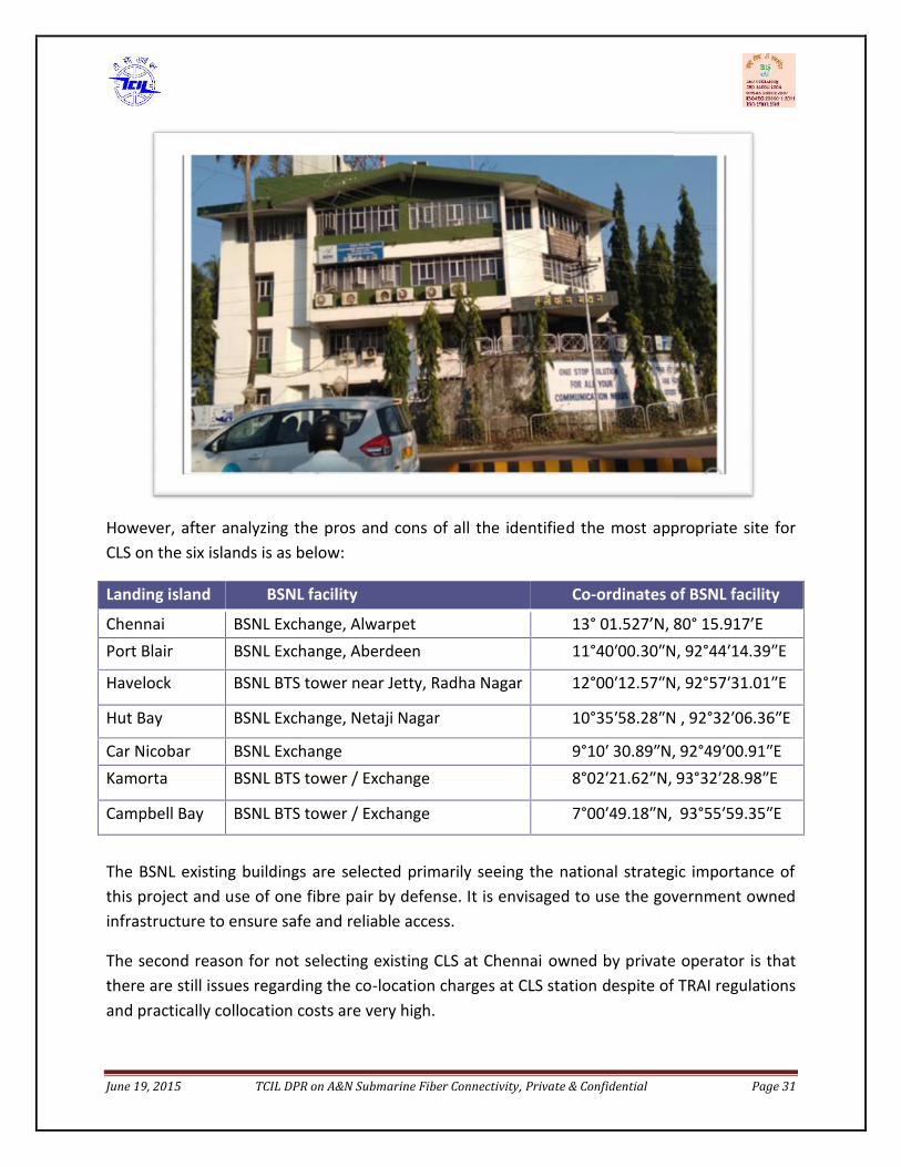
June 19, 2015 TCIL DPR on A&N Submarine Fiber Connectivity, Private & Confidential Page 31
However, after analyzing the pros and cons of all the identified the most appropriate site forCLS on the six islands is as below:
Landing island BSNL facility Co-ordinates of BSNL facility
Chennai BSNL Exchange, Alwarpet 13° 01.527’N, 80° 15.917’EPort Blair BSNL Exchange, Aberdeen 11°40ʹ00.30ʺN, 92°44ʹ14.39ʺE
Havelock BSNL BTS tower near Jetty, Radha Nagar 12°00ʹ12.57ʺN, 92°57ʹ31.01ʺE
Hut Bay BSNL Exchange, Netaji Nagar 10°35ʹ58.28ʺN , 92°32ʹ06.36ʺE
Car Nicobar BSNL Exchange 9°10ʹ 30.89ʺN, 92°49ʹ00.91ʺEKamorta BSNL BTS tower / Exchange 8°02ʹ21.62ʺN, 93°32ʹ28.98ʺE
Campbell Bay BSNL BTS tower / Exchange 7°00ʹ49.18ʺN, 93°55ʹ59.35ʺE
The BSNL existing buildings are selected primarily seeing the national strategic importance ofthis project and use of one fibre pair by defense. It is envisaged to use the government ownedinfrastructure to ensure safe and reliable access.
The second reason for not selecting existing CLS at Chennai owned by private operator is thatthere are still issues regarding the co-location charges at CLS station despite of TRAI regulationsand practically collocation costs are very high.
June 19, 2015 TCIL DPR on A&N Submarine Fiber Connectivity, Private & Confidential Page 32
To save the equipment in the event of Tsunami, it is suggested to house the equipment on 1st /2nd floor of the cable landing station building. Alternatively , the CLS can be constructed in newbuilding within the compound of identified BSNL complex and they can be protected in steelwalls.
3.1.2.1.1.1. Cable Landing Station Construction PracticesOnce the selection of the landing station site has been made by the cable owner, the landingstation itself would need to be planned. For maintaining communication redundancy, landingstations of two cable systems are preferably not planned within one complex or building.
The main parameters that go into the planning of cable landing station are;
Provision for an equipment room Provision for utilities room and open space for generators Provision for Dual source AC grid power Provision for a secured cable-chute (duct) leading into the equipment room (cable vault, if
necessary) Provision for station earth Provision for cable Station infrastructure (mentioned in next section)
The equipment room should in general provide a secured and direct access of the cable to theequipment room and easy movement and installation of the equipment should be possible. Ifthe equipment room is planned on a multi-level building, the load factor of all the equipmentrequired to be installed on that level (for design capacity) need to be kept in to consideration.
The utility arrangements and the site-space most often vary from one landing station site toanother. Hence a lot of customization is required in planning the equipment floor for any givenlanding station site. Part of utilities (Electric panels, DCDB, AC units) sometimes are alreadyavailable in a common floor and cannot be installed in the equipment floor space and othertimes, they might necessarily be needed to be installed at the equipment floor space due toconstraints elsewhere. Similarly, the balance between length and width of the equipment floorcould be achieved by efficiently performing the interplay between number of rows, racks perrows and placement of equipment types. The transmission equipment types also sometimesdiffer from supplier to supplier and determine the installation arrangement (eg: front and backopening, back-to-back installation possibility, heat dissipation areas etc)
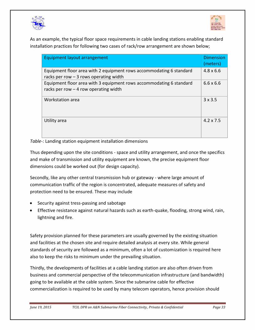
June 19, 2015 TCIL DPR on A&N Submarine Fiber Connectivity, Private & Confidential Page 33
As an example, the typical floor space requirements in cable landing stations enabling standardinstallation practices for following two cases of rack/row arrangement are shown below;
Equipment layout arrangement Dimension(meters)
Equipment floor area with 2 equipment rows accommodating 6 standardracks per row – 3 rows operating width
4.8 x 6.6
Equipment floor area with 3 equipment rows accommodating 6 standardracks per row – 4 row operating width
6.6 x 6.6
Workstation area 3 x 3.5
Utility area 4.2 x 7.5
Table-: Landing station equipment installation dimensions
Thus depending upon the site conditions - space and utility arrangement, and once the specificsand make of transmission and utility equipment are known, the precise equipment floordimensions could be worked out (for design capacity).
Secondly, like any other central transmission hub or gateway - where large amount ofcommunication traffic of the region is concentrated, adequate measures of safety andprotection need to be ensured. These may include
Security against tress-passing and sabotage Effective resistance against natural hazards such as earth-quake, flooding, strong wind, rain,
lightning and fire.
Safety provision planned for these parameters are usually governed by the existing situationand facilities at the chosen site and require detailed analysis at every site. While generalstandards of security are followed as a minimum, often a lot of customization is required herealso to keep the risks to minimum under the prevailing situation.
Thirdly, the developments of facilities at a cable landing station are also often driven frombusiness and commercial perspective of the telecommunication infrastructure (and bandwidth)going to be available at the cable system. Since the submarine cable for effectivecommercialization is required to be used by many telecom operators, hence provision should
June 19, 2015 TCIL DPR on A&N Submarine Fiber Connectivity, Private & Confidential Page 34
be available that these telecom operators have convenience of building their networks up tothe cable landing site and a standard inter-connection facility exists.
These may include;
Provision for meet-me-room for other telecom users and backhaul providers International datacenter level infrastructure for meet-me-room Provision for backhauling from meet-me-room
As three to four distinct aspects are required to be considered while planning for cable landingstation and several parameters of these aspects play an important role in determining overallutility of cable landing station, hence the planning is usually undertaken by a joint team ofexperts capable of ensuring specialized needs of all aspects - submarine project execution,submarine cable O&M, utility, civil and infrastructure aspects and meet-me-roominfrastructure.
The cable landing station planning and development activities are usually commenced inparallel when the supply contract comes into force as the specifics of equipment, cable,footprint, power consumption are by then finalized along with clarity of available space andresources and business plans. These activities usually go on for several months, evolvingfrequently as best suited option are continually explored and tried.
The timely readiness of cable station, land route and BMH within the deadline as included inthe supply contract plan of work of the chosen supplier, is of utmost importance in order to notto have claims and delays from the supplier. With this view, it is also important that during thecontract signature, while mutually agreeing the plan of work, adequate time for cable stationand relate infrastructure readiness is carefully allotted and considered along with other relatedactivities of the project supplier.
3.1.2.1.1.2. Infrastructure within the cable landing stationOther main infrastructure elements of a typical cable landing station are as following:
I. Power plant (-48V DC)This would include complete set up of SMPS, rectifier, battery bank and electric panels. TheSMPS cabinet nowadays house AC distribution cabinets with control unit, DC Distributioncabinet with control unit, Rectifier rack with monitoring module and Rectifiers. Usually 2000Amps SMPS scalable up to 4000 Amps are preferred for cable station needs.
II. DG sets for AC power back-upThe DG set is proposed as emergency backup against failure of grid supply for network andpower equipment like SMPS, Air- conditioning and Lighting. The generator will be sized to

June 19, 2015 TCIL DPR on A&N Submarine Fiber Connectivity, Private & Confidential Page 35
supply the transmission equipment load, the UPS (Un-interruptible Power Supply) in theultimate configuration, air- conditioning and other utilities in the station and would be providedin a 1+1 configuration. Usually 20-25 kVA DG sets suffice for cable station needs.
III. Precision AC (PAC) UnitsThese are independent units capable of providing 0.80 to 0.90 sensible heat ratios for effectiveand efficient cooling required in equipment floors where movement of people is low.
IV. Fire detection, alarm & control systemThe laser based early warning smoke detection VESDA system is used as fire detection system.The VESDA panel shall be compatible to transfer the signals to Fire detection panel.FM200 Fire suppression systems are generally preferred for such needs The main advantage ofFM200 fire suppression system is that they can reach extinguishing levels in 10 seconds orless,and require small amount of agent required to suppress a fire resulting in lesser spacerequirement.
V. Water Leak detection systemWater leak detection control panel of 4 zone / 8 zone type consisting with features like,auxiliary alarm contacts, monitored alarm outputs, Open & short circuit line monitoring, BrightLED's for indication are typically used.
VI. Rodent RepellantsThe Rodent repellent Pest control system usually consists of Master Console capable ofconnecting to 12 Satellites, Satellite Units complete & Connecting Cables with conduits,junctions boxes and all accessories as required.
VII. CCTV &Access systemThe building management system will comprise of software package, which would allowseamless integration of Access Control, BMS, Fire services, CCTV etc.False flooring for proper flow of the cooling air through the equipment rack (bottom to top) andimproving equipment access and cabling maintenance is preferred while setting up the cableinfrastructure.
3.1.2.1.2. Terrestrial Cable including TrenchesThe terrestrial land cable shall connect the submarine cable terminating in a cable terminationbox in Beach Manhole to the Cable landing station equipment. The land cable route from theBMH to the landing station needs to be prepared by the cable owner. Its construction isundertaken along with the BMH construction after relevant approvals are in place.

June 19, 2015 TCIL DPR on A&N Submarine Fiber Connectivity, Private & Confidential Page 36
The usual practice for constructing land route is to use 110mm (OD) HDPE, in a concreteencasing, covered with soft soil and warning tape at usually 1.5 m depth. Hand holes at regularintervals need to be provided for ease of cable pulling. The distance and size of hand holes areusually dependent upon how many ducts are to be laid and for what length (cable station toBMH).
Depending upon the land cable type to be used (sometime its similar to submarine cable, othertimes the power cable is separated) one main duct with sub-ducts or two separate main ductscould be used for landing one segment cable. If there are more than one segments plannedthrough one common land route, its preferred to use sub-ducts, in order to keep distinctioneasy for repair team during repairs.
The activities involved in cable laying include:
I. Site Survey & Cable Installation
The installation of land cable shall include site survey to assess the suitability of route. Thisoperation shall include delivery of land cable to each site, laying of ducts in the selected route,pulling in of the land cables to the ducts, plus all cable landing jointing & testing. As a segmentin this submarine cable system from Chennai to Port Blair is repeatered, the land cable willcombine optical and power transmissions with a single cable structure.
II. Cable Terminations
The land cable will be connected into the cable termination cubicle at the terminal station withthe appropriate connections for system monitoring, safety etc. Following the satisfactorylanding of the shore end section of the land cable. This joint will be secured within the beachmanhole.
III. Power Feed Earth (PFE)
PFE system at each of the landing locations will consist of an earth array (up to 8 electrodes)with a cable connection to the terminal station. Typically, the array will be installed at thebeach , near the beach manhole and the connecting cable will be pulled into a sub-duct withinthe same duct as for the land cable. The electrodes to be installed within 25 meters from theBMH, and in sandy/ normal soil type conditions to a maximum depth of 4.0 meters.
The protection of land cable is critical to ensure seamless working of the whole submarinesystem as any cut due to undesirable activity shall disrupt the whole traffic. As this land cable isjointed with submarine cable inside beach manhole with a lot of precision, diversification ofland cable through another route to ensure redundancy is not feasible. Therefore, it is

June 19, 2015 TCIL DPR on A&N Submarine Fiber Connectivity, Private & Confidential Page 37
suggested to install sensors along the duct and CCTV cameras for 24*7 monitoring of land cableroute.
3.1.2.1.3. Terminal EquipmentThe CLS has the terminal equipment in it, which broadly consists of 1) Power Feedingequipment 2) Submarine Line Terminating Equipment and 3) Transmission Equipment (whichincludes DWDM, STM etc). In addition to this, there is Network Management System (NMS) andaccessories like ODF for patching the optical fiber.
i. Cable Termination Box (CTB): also known as Beach joint Box. It is placed inside theBeach manhole, and is a jointing box where submarine cable terminates and connects tothe land cable.
ii. Cable Termination Rack: The CTR is used for terminating the cable in the landing stationsof an unrepeater-ed segment. The cable enters either via the top or the bottom of therack, and is secured in a cable-terminating manifold from where the individual fibersinside the cable are taken to an Optical Fibre Distribution unit. In the fiber distributionunit fibers from cable are spliced to fibers going to the SLTE. The CTR usually alsocomprises a cable testing & monitoring facility, and electrical testing (electroding)functions. One CTR rack can also be used to terminate two cables.
iii. Line Terminal Equipment (LTE): It comprises of all equipment in a terminal stationincluding SLTE, Power Feeding Equipment (PFE), maintenance Controller (MC), internalODF.
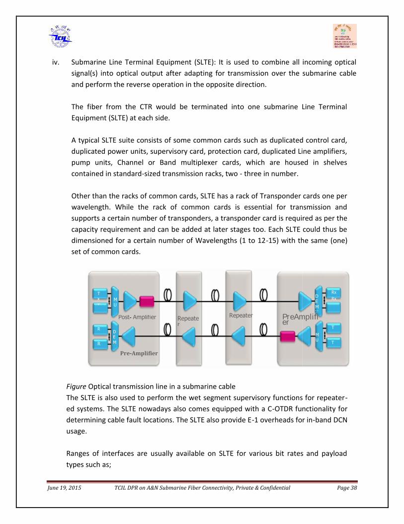
June 19, 2015 TCIL DPR on A&N Submarine Fiber Connectivity, Private & Confidential Page 38
iv. Submarine Line Terminal Equipment (SLTE): It is used to combine all incoming opticalsignal(s) into optical output after adapting for transmission over the submarine cableand perform the reverse operation in the opposite direction.
The fiber from the CTR would be terminated into one submarine Line TerminalEquipment (SLTE) at each side.
A typical SLTE suite consists of some common cards such as duplicated control card,duplicated power units, supervisory card, protection card, duplicated Line amplifiers,pump units, Channel or Band multiplexer cards, which are housed in shelvescontained in standard-sized transmission racks, two - three in number.
Other than the racks of common cards, SLTE has a rack of Transponder cards one perwavelength. While the rack of common cards is essential for transmission andsupports a certain number of transponders, a transponder card is required as per thecapacity requirement and can be added at later stages too. Each SLTE could thus bedimensioned for a certain number of Wavelengths (1 to 12-15) with the same (one)set of common cards.
Figure Optical transmission line in a submarine cableThe SLTE is also used to perform the wet segment supervisory functions for repeater-ed systems. The SLTE nowadays also comes equipped with a C-OTDR functionality fordetermining cable fault locations. The SLTE also provide E-1 overheads for in-band DCNusage.
Ranges of interfaces are usually available on SLTE for various bit rates and payloadtypes such as;
DEMUX
MUX
MUX
DEMUX
RxRx
Tx
Tx
TxTx
Rx
Rx
Pre-Amplifier
Post- Amplifier PreAmplifierPost-Amplifier
Repeater
Repeater

June 19, 2015 TCIL DPR on A&N Submarine Fiber Connectivity, Private & Confidential Page 39
100G: OTU-440G: STM-256, OC-768, OTU-310G: STM-64, OC-192, OTU-2, OUT-2e, 10GE LAN PHy
In Andaman system each LTE is configured, on day 1,to send/receive 1 wavelength at100Gb/sequipment on the line side, while on the client (backhaul) side it would beconnected to the SDH equipment through a 10G I64.1 interface.
Courtesy: NEC
v. Power Feeding Equipment (PFE): It is used to power the undersea repeaters from theterminal station by converting -48V power to a constant current. The PFE shall beinstalled only at Chennai & Port Blair being the repeatered segment. To improve thereliability of the system power feeding, power feeding equipment sets with thecapability of feeding all the system voltages requirement are installed at landing stationat both ends of the system. The voltages to be supplied to the submarine repeaters areallocated to supply the power feeding equipment at both ends.
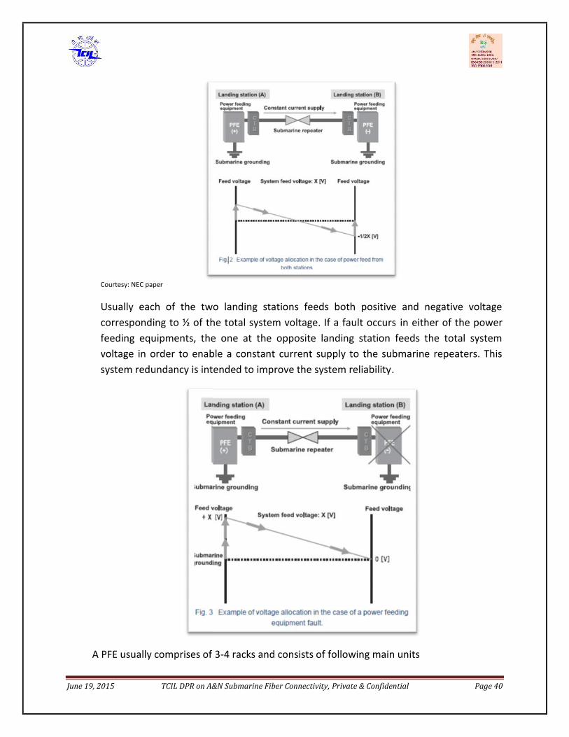
June 19, 2015 TCIL DPR on A&N Submarine Fiber Connectivity, Private & Confidential Page 40
Courtesy: NEC paper
Usually each of the two landing stations feeds both positive and negative voltagecorresponding to ½ of the total system voltage. If a fault occurs in either of the powerfeeding equipments, the one at the opposite landing station feeds the total systemvoltage in order to enable a constant current supply to the submarine repeaters. Thissystem redundancy is intended to improve the system reliability.
A PFE usually comprises of 3-4 racks and consists of following main units
June 19, 2015 TCIL DPR on A&N Submarine Fiber Connectivity, Private & Confidential Page 41
Power converter units to convert the low voltage DC to the very high voltage DCneeded to power the submarine cable at a constant current. Number of converterunits needed is as per power voltage rating of the PFE, which in turn is dependentupon segment length. A spare converter unit is usually part of PFE .
A Dummy Load for offline testing of the PFE to avoid any damage to the wet plant Control unit from where the PFE functions are monitored and controlled. Duplicated
control units are provided within the PFE Cable Terminating Equipment for interconnecting the submarine cable, the System
Earth and the dedicated Station Earth
As the PFE handles high voltage, the PFE racks are secured by closed doors and several keyarrangements. Any attempt to gain access to cable or HV units would lead to an automaticPFE shutdown causing the traffic outage on the segment.
The size of the PFE (number of racks) is dependent upon its rated current and voltageoutput, which is in turn dependent upon segment length and is achieved by adding moreconverter units in series. Usually 4-5 rack space is required for a duplicated 6kW PFE. PFEracks are not standard 600mm dimensioned but slightly larger.
vi. Internal ODF: This is Optical distribution Frame (also known as FDF) where the cableinterfaces is terminated and where the SLTE is connected to the SIE.
vii. Maintenance Controller (MC): The MC is used to supervise the SLTE, the PFE and thesubmerged plant from a human computer interface. The MC shall be there in eachterminal station and shall allow quick localization and trouble shooting.
The wet plant supplier will provide a Maintenance Controller (MC) in 1+1 configurationfor managing the SLTE of the entire network. The Maintenance controller wouldcomprise of servers and workstations and have a centralized architecture. At everylanding station, a Local Craft Terminal (LCT), which is usually a laptop would be availableseparately for SLTE and SIE for local access and trouble shooting of the equipment alongwith a spare.
The SDH supplier will provide its NMS in1+1 configuration for managing the entireSDH network. The NMS would comprise of servers and workstations and have acentralized architecture.
Both the MC and NMS servers would be located at the main NOC and back-up NOClocations. The BNOC would be a hot standby of the NOC servers and would act as adisaster recovery center (DRC).The NOC team would manage the cable systemnetwork through the MC and NMS workstations.

June 19, 2015 TCIL DPR on A&N Submarine Fiber Connectivity, Private & Confidential Page 42
The connection of all nodes (equipment) of all landing station to MC and NMS serversand workstations would by via a DCN (data connection network), which would beprovisioned through e-1 overheads of the transponder. The nodes correspond withthe server usually on a TCP/IP protocol.
The DCN would also be used to provide the IP / EPABX based order wire between theNOC and cable landing stations.
A reliable DCN link is essential to provide continuous visibility of the network to theNOC. A cable fault would however mean the isolation of the one side of the networkfor which a 2Mb satellite link would be needed to act as ADCN link.
viii. SDH/Interconnection Equipment (SIE): The SIE would provide the add/drop and cross-connect functions for terminating traffic in a landing station. The 10G client signals fromSLTE would be terminated on the SDH equipment and can be cross connected to severallower order ports as per customer needs at any landing site. A standard SDH box usuallyhas internally duplicated matrix and control cards and also power supply and fan units.It comprises of all the equipment which provides interconnection between adjacent linesegments and the domestic network in a terminal station including Network Elements(NEs), Element Management Systems (EMS), Network Management system, ExternalODF, data communication network associated with SIE. It may also include the humancomputer interfaces that may be located outside the terminal station and connected tothe management system through the external network and used to supervise thesystem.
ix. External ODF: It is ODF/FDF where system interface is terminated and where the SIE isconnected to the terrestrial equipment (SDH-64 etc.)
x. Network Synchronization: For Andaman system, if existing BSNL network is not havingstratum 1 Primary Reference Clock source (already feeding less than 20 units) atChennai or Port Blair to synchronize cable network also, then a separate PRC sourcewould need to be installed in 1+1 mode at Chennai and Port Blair for providingnetwork synchronization.
The G.811 level PRC source comprises of a GPS receiver (small antenna and modularunit) that connects through a SSU to multiple network elements.
The synchronization network would be supplied, configured and installed by the mainsystem supplier.
June 19, 2015 TCIL DPR on A&N Submarine Fiber Connectivity, Private & Confidential Page 43
xi. Network Management: The Network management will be made of two components :a) A redundant maintenance controller (MC) dedicated to the management of the
submarine part of the system based on two software applications:o Element Manager – it integrates information from the submarine network
elements of the system (i.e. SLTE and PFE). The submarine optical path managerallows the supervision of the offered submerged plant as well as the end to endwavelengths and network powering configuration.
o Network Manager at terminal station. It may also be located outside terminalstation at a central place.
b) The NMS functions are broadly as below: Performance Management Fault Management Configuration Management Security Management
xii. Data Communication Network: The Data Communication network (DCN) is a dedicatedsystem supporting the communications between the network elements (e.g. SLTE, PFEetc.) and Network Management elements (e.g. Servers and Operator Positions) for alllanding sites.
xiii. Network Protection: For traffic protection, it is planned to implement the followingprotection schemes through the SDH equipment between SDH and SLTE:
Multiplex Section Protection (MSP) 1+1 (from day 1 equipage): to provideprotection against transponder failure
Sub-Network Connection Protection (SNCP): to provide path level protectionfor specific users
MSP 1+1 configured on the DLS terminating ports of the 2 fiber pairs on the SDHequipment would provide the multiplex section protection. Thus it will provideprotection against traffic interruption on one fiber pair due to any reason betweenthe two SDH equipment of the segment, including a transponder failure. Due to MSPprotection, the traffic would automatically get routed through the other fiber pair ofthe segment and would thus avoid any interruptions.
As with increase of traffic, more 10G get commissioned, it could be configured inMSP through a vacant 10G on the other fiber pair. Whenever the transponder failurerate reduces to low levels, the MSP 1+1 could be modified into MSP 1+n for effectiveutilization of equipment.
June 19, 2015 TCIL DPR on A&N Submarine Fiber Connectivity, Private & Confidential Page 44
The SNCP protection would provide a dedicated path level protection to specificusers who require protection against any transponder failure scenario. SNCP could beused when all traffic terminating in a station need not be protected and theprotection facility is to be provided only to specific users.The two protection schemes, MSP & SNCP, configured through SIE provide for anefficient and complete way of traffic protection including against transponderfailures. It is a suitable and more efficient way of traffic protection popularlydeployed across cable systems for long.
The detailed specifications of above system components are given in the Part –II of thereport submitted by DTS vendor.
3.1.2.1.4. Terminal Station - System DesignThe submarine cable shall be terminated at Beach Manhole where it will be joint with landcable and power feed cable. The land cable shall be terminated in the CTB / CTR (CableTermination Box/ Rack) and power feed cable shall be terminate into the PFE (Power feedingEquipment) inside the cable landing station building. The PFE shall work in the dual feed toensure redundancy. The fibers from the CTR shall go into the SLTE with 1 SLTE for each fiberpair.
In this project, system protection is provided by lighting 2 fiber pair i.e. (1+1) with half traffic oneach through each pair to corresponding SLTE. The third pair kept reserved for defense. Thering redundancy shall be obtained through SNCP (Sub Network connection protection) at SDHlevel towards customer side.
At Chennai & Port Blair SLTE with provision for 64 lambdas (@ 100 Gbps per lambda) shall beprovisioned with initial equipped card of one lambda of 100 Gbps. As two fibers will be lit sothere shall be two SLTEs at each station.
For other five islands i.e. Little Andaman, Car Nicobar, Havelock, Kamorta & Great Nicobar as allof them have low population, the same redundancy and equipage of SLTE shall be done but thescalability of SLTE shall be for 8 /16 lambdas depending on the availability with manufacturer.This shall ensure saving in common cards of control card, power units, supervisory card,protection card, Line amplifiers, pump units, Channel or Band multiplexer cards etc.
The SDH interconnect Equipment facing line interfaces towards customer side shall have crossconnected function and multiple ports as follows:
1. 10 GigE Ethernet2. 10 Gbps OTU2

June 19, 2015 TCIL DPR on A&N Submarine Fiber Connectivity, Private & Confidential Page 45
3. STM-644. STM-16
The no. of ports shall vary and depend on manufacturer. The SDH / SIE equipment shall be beindigenous and procured from Indian manufacturers.
June 19, 2015 TCIL DPR on A&N Submarine Fiber Connectivity, Private & Confidential Page 45
3. STM-644. STM-16
The no. of ports shall vary and depend on manufacturer. The SDH / SIE equipment shall be beindigenous and procured from Indian manufacturers.
June 19, 2015 TCIL DPR on A&N Submarine Fiber Connectivity, Private & Confidential Page 45
3. STM-644. STM-16
The no. of ports shall vary and depend on manufacturer. The SDH / SIE equipment shall be beindigenous and procured from Indian manufacturers.

Network Diagram
Line - Capacity of 6.4 Tbps (64 X 100 Gbps per lambda)Initial lit capacity of 100 Gbps
Client - Client interfaces like STM-16/64, OTU-1/2, 1/100 GigE
SLTE1
SLTE1’
Port Blair
SLTE3
SLTE3’
SLTE4
Havelock
Little Andaman
Car Nicober
SLTE2
SLTE2’
FP1
FP2
FP2
Chennai
SLTE3
SLTE4
SLTE3’
SLTE3
SLTE3’
SLTE3
SLTE3’
FP1
FP1
FP2
SLTE5
SLTE5
SIESIESIE
3.1.2.2. Submerged Plant/Wet PlantSubmerged Wet plant consists of all the equipment under the sea including submarine cable,repeaters, branching unit, equalizers, etc. It includes the submarine cable upto the BeachManhole (BMH), including the Beach Manhole itself and the joint inside the BMH, it alsoincludes the station sea earth and its cabling upto the BMH. The main characteristics to beconsidered while designing the wet plant shall be: Proposed submarine cable features strong protection against external aggressions
owing to its steel vault and armors. Proposed repeaters are designed for wideband applications. Proposed submerged equipments are fully accessible and operable by the network
management system which provides monitoring facilities for preventive maintenance ofthe cable system.
3.1.2.2.1. Beach Manhole (BMH)BMH is a manhole near the sea shore where submarine fiber cable terminates and power andfiber separates. After this land cable and power cable are connected to fiber and copperconductor respectively which is extended to cable landing station.
Beach manhole is a special secured concrete chamber located on the beach (below the ground)where the submarine cable is landed on the ground. After the cable enters the BMH, throughthe slip hole made on the lower side of the seaward wall, its protective covering is stripped andclamped on the wall. The fiber and power conductors from the un-armoured cable are thenseparated and by means of a special beach joint are separately connected to a land and earthcable coming from the cable landing station.
The side-wall, adjacent to the one having the entry slip hole, has got four clamps adequatelydistanced allowing sufficient spare length of submarine cable to be coiled inside the BMH andalso hold the beach joint.
The BMH should be secured by means of a locking arrangement, in order to keep it out of reachfrom anyone other than the authorized maintenance staff.Care should also be taken that thelocation of the BMH on the beach is so chosen that the shore currents do not wash away thebeach sand and over a period of time expose the BMH walls to the sea waves thus leading to apotential threat of the BMH getting collapsed or washed away.
The sea earth (or ocean ground) is usually provisioned near the BMH,on the beach. These daysmost of the suppliers use the earthing electrodes (4-8 numbers) instead of one large circularearth plate. Depending upon the electrode security on the beach (in future from any potential

June 19, 2015 TCIL DPR on A&N Submarine Fiber Connectivity, Private & Confidential Page 48
construction activity) and also the soil resistance or cable length resistance, the earthingelectrodes can alternatively be installed in the proximity of cable landing station or any othersuitable area.
The BMH construction usually falls within the cable owner’s responsibilitylike other civilconstructions - cable station and land route. The BMH construction can be commenced oncethe CRZ clearance and permissions from relevant agencies (local municipality, beach landowning agency etc.) is available. The BMH dimensions are typically 6’ x 8’ x 8’.
The criteria for selection of potential suitable Beach Manhole (BMH) sites are:
• Proximity to CLS• Basic considerations
• Natural Factors• Human Impacts• Engineering Requirements
• Accessibility• Possibility of Interference with existing facilities• Impact of Fishing, Shipping and Future development• Ease of installation and maintenance• Impact of Overall cable route
The team of DTS vendor has conducted site visits to all the beaches and identified the potentialBMH locations considering all the factors as mentioned above. The detailed site visit of eachisland including the pictures of and Chennai is placed at Appendix B of the Past-I of DTS Report.A sample picture of identified BMH at Port Blair is shown below:
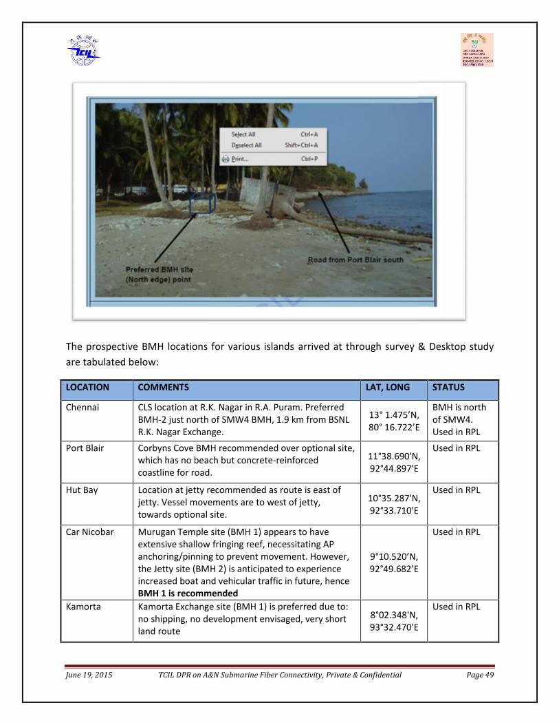
June 19, 2015 TCIL DPR on A&N Submarine Fiber Connectivity, Private & Confidential Page 49
The prospective BMH locations for various islands arrived at through survey & Desktop studyare tabulated below:
LOCATION COMMENTS LAT, LONG STATUS
Chennai CLS location at R.K. Nagar in R.A. Puram. PreferredBMH-2 just north of SMW4 BMH, 1.9 km from BSNLR.K. Nagar Exchange.
13° 1.475’N,80° 16.722’E
BMH is northof SMW4.Used in RPL
Port Blair Corbyns Cove BMH recommended over optional site,which has no beach but concrete-reinforcedcoastline for road.
11°38.690'N,92°44.897'E
Used in RPL
Hut Bay Location at jetty recommended as route is east ofjetty. Vessel movements are to west of jetty,towards optional site.
10°35.287'N,92°33.710'E
Used in RPL
Car Nicobar Murugan Temple site (BMH 1) appears to haveextensive shallow fringing reef, necessitating APanchoring/pinning to prevent movement. However,the Jetty site (BMH 2) is anticipated to experienceincreased boat and vehicular traffic in future, henceBMH 1 is recommended
9°10.520’N,92°49.682’E
Used in RPL
Kamorta Kamorta Exchange site (BMH 1) is preferred due to:no shipping, no development envisaged, very shortland route
8°02.348'N,93°32.470'E
Used in RPL
June 19, 2015 TCIL DPR on A&N Submarine Fiber Connectivity, Private & Confidential Page 50
Campbell Bay BMH 1 site appears to have rock outcrop andfringing reef, necessitating AP anchoring/pinning toprevent movement. Recommend use of BMH 2 site 07°00.796’N,
93°56.168’E
BMH 1 sitecurrently usedin RPL
Havelock Area east of access track is at potential risk fromrivulet outflow. BMH 1 relocated approximately100m west of outflow. 11°59.028'N,
92°57.197'E
Location E ofaccess trackcurrently usedin RPL
The risk assessment for the landing site BMH identified above is tabulated below:
Chennai CLS location BSNL Exchange at R.K. Nagar, R.A. Puram. Preferred BMH 2 just north ofSMW4 BMH. Moving BMH north of TIISCS BMH to eliminate inshore cable crossingnot advisable as it would be too near Chennai Port, where cable damage has beenreported in the past.
Port Blair Corbyns Cove landfall preferred over optional site, which has no beach but concrete-reinforced coastline for road.
Hut Bay Location east of jetty preferred; no issues identified. Vessel movements are to westof jetty, towards optional site.
Car Nicobar Murugan Temple site (BMH 1) is preferred, though it appears to have extensiveshallow fringing reef, necessitating AP anchoring/pinning to prevent movement.However, the Jetty site (BMH 2) is anticipated to experience increased boat andvehicular traffic in future
Kamorta Kamorta Exchange site (BMH 1) is preferred due to: no shipping, no developmentenvisaged, very short land route
Campbell Bay BMH 2 (southern) site is preferred. BMH 1 (northern) site appears to have rockoutcrop and fringing reef, necessitating AP anchoring/pinning to prevent movement.
Havelock Preferred location BMH 1 located approximately 70m west of access track. Area eastof access track is at potential risk from river outflow.

June 19, 2015 TCIL DPR on A&N Submarine Fiber Connectivity, Private & Confidential Page 51
3.1.2.2.2. Submarine Optical Fiber Cablei. Fiber Count
Generally, world-wide submarine cables are laid by consortium of various telecomoperators sharing bandwidth from country to country. It is seen that globally no. of fiberpair (fp) laid vary from 2fp to 8fp depending upon the requirements in submarine cablecommercially. Although the DTS vendor report has recommended two fiber pair but TCILview is as below.Seeing the national & strategic importance of this project TCIL recommends that theSubmarine sea cable between Chennai to Port Blair and other five islands shall consist ofthree fiber pair. The use of each fiber per pair in the submarine cable is as below:a. One pair for telecom connectivity to A&N islands.b. One pair for dedicated use by defense forces.c. The third fiber pair will also be lit and be used for providing redundancy to the first fiber
pair.
The cost of 4fp, 5fp & 6fp is also included for ready reference in decision making.
Number of fiber pairs Incr. cost
(USD mn.)
4 Fiber pairs 3.0
5 Fiber pairs 6.0
6 Fiber pairs 8.9
ii. Submarine Cablea. Broad Specifications The cable for the entire route consists of combinations of sections of different kinds of
cable connected together depending upon the water depths and sea-bed conditions.The difference comes in the form of armoring made around it. While shallower sectionsare more heavily ‘armored’ the deep-water cable is least ‘armored’. These are furtherdefined and referenced as per ITU-T recommendation in the technical specificationchapter related to submarine cables.
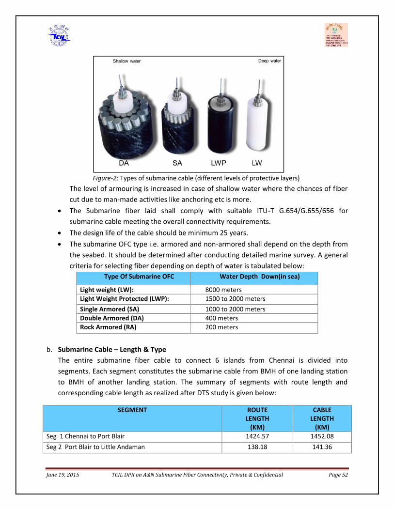
June 19, 2015 TCIL DPR on A&N Submarine Fiber Connectivity, Private & Confidential Page 52
Figure-2: Types of submarine cable (different levels of protective layers)The level of armouring is increased in case of shallow water where the chances of fibercut due to man-made activities like anchoring etc is more.
The Submarine fiber laid shall comply with suitable ITU-T G.654/G.655/656 forsubmarine cable meeting the overall connectivity requirements.
The design life of the cable should be minimum 25 years. The submarine OFC type i.e. armored and non-armored shall depend on the depth from
the seabed. It should be determined after conducting detailed marine survey. A generalcriteria for selecting fiber depending on depth of water is tabulated below:
Type Of Submarine OFC Water Depth Down(in sea)
Light weight (LW): 8000 metersLight Weight Protected (LWP): 1500 to 2000 metersSingle Armored (SA) 1000 to 2000 metersDouble Armored (DA) 400 metersRock Armored (RA) 200 meters
b. Submarine Cable – Length & TypeThe entire submarine fiber cable to connect 6 islands from Chennai is divided intosegments. Each segment constitutes the submarine cable from BMH of one landing stationto BMH of another landing station. The summary of segments with route length andcorresponding cable length as realized after DTS study is given below:
SEGMENT ROUTELENGTH
(KM)
CABLELENGTH
(KM)Seg 1 Chennai to Port Blair 1424.57 1452.08Seg 2 Port Blair to Little Andaman 138.18 141.36
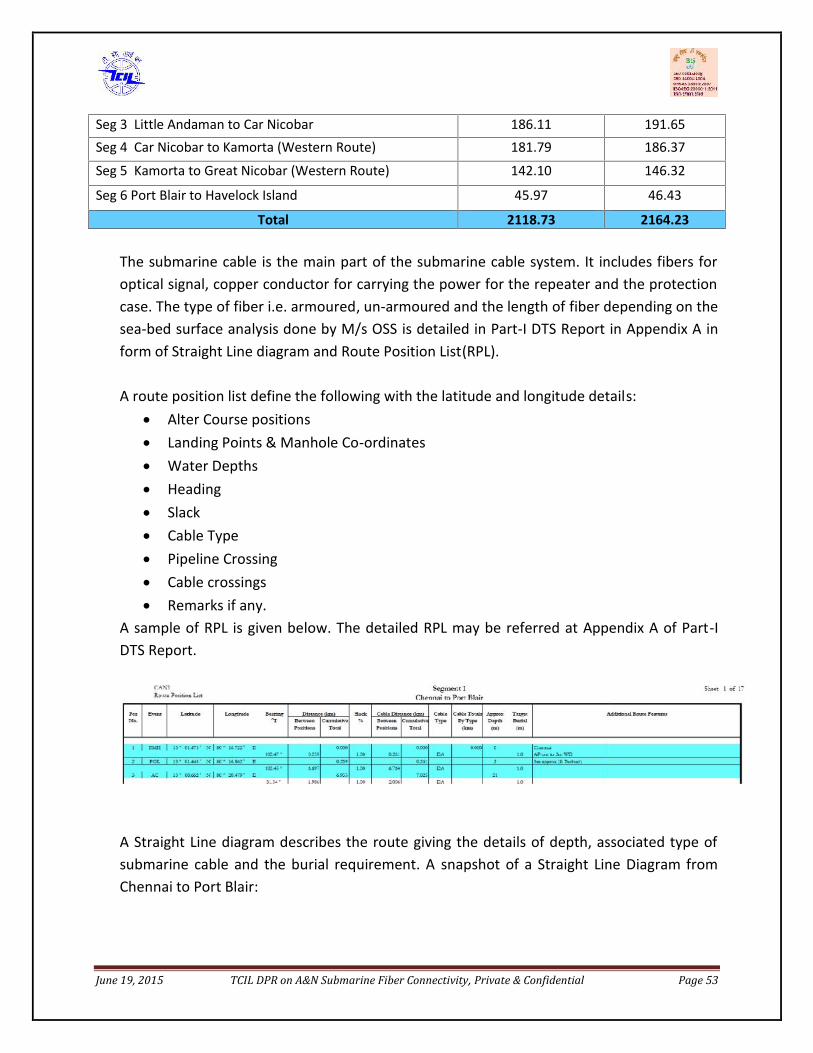
June 19, 2015 TCIL DPR on A&N Submarine Fiber Connectivity, Private & Confidential Page 53
Seg 3 Little Andaman to Car Nicobar 186.11 191.65Seg 4 Car Nicobar to Kamorta (Western Route) 181.79 186.37
Seg 5 Kamorta to Great Nicobar (Western Route) 142.10 146.32
Seg 6 Port Blair to Havelock Island 45.97 46.43
Total 2118.73 2164.23
The submarine cable is the main part of the submarine cable system. It includes fibers foroptical signal, copper conductor for carrying the power for the repeater and the protectioncase. The type of fiber i.e. armoured, un-armoured and the length of fiber depending on thesea-bed surface analysis done by M/s OSS is detailed in Part-I DTS Report in Appendix A inform of Straight Line diagram and Route Position List(RPL).
A route position list define the following with the latitude and longitude details: Alter Course positions Landing Points & Manhole Co-ordinates Water Depths Heading Slack Cable Type Pipeline Crossing Cable crossings Remarks if any.
A sample of RPL is given below. The detailed RPL may be referred at Appendix A of Part-IDTS Report.
A Straight Line diagram describes the route giving the details of depth, associated type ofsubmarine cable and the burial requirement. A snapshot of a Straight Line Diagram fromChennai to Port Blair:
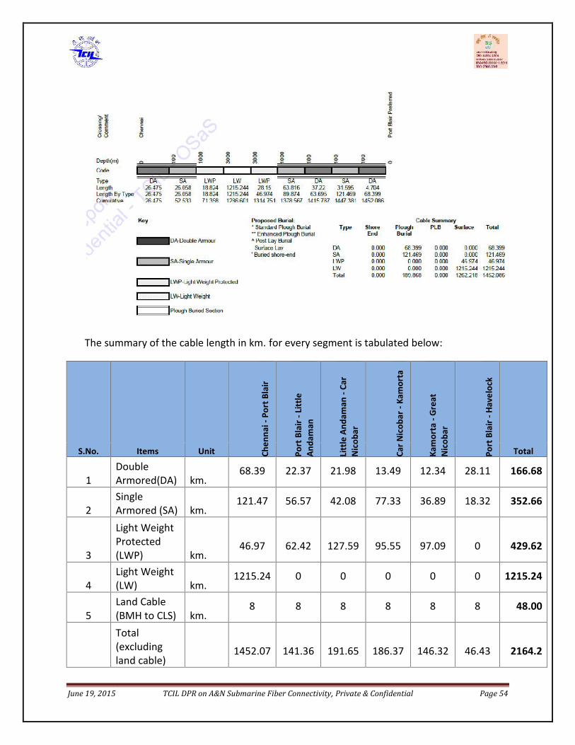
June 19, 2015 TCIL DPR on A&N Submarine Fiber Connectivity, Private & Confidential Page 54
The summary of the cable length in km. for every segment is tabulated below:
S.No. Items Unit Chen
nai-
Port
Bla
ir
Port
Bla
ir-L
ittle
Anda
man
Litt
le A
ndam
an-C
arN
icob
ar
Car N
icob
ar-K
amor
ta
Kam
orta
-Gre
atN
icob
ar
Port
Bla
ir-H
avel
ock
Total
1DoubleArmored(DA) km.
68.39 22.37 21.98 13.49 12.34 28.11 166.68
2SingleArmored (SA) km.
121.47 56.57 42.08 77.33 36.89 18.32 352.66
3
Light WeightProtected(LWP) km.
46.97 62.42 127.59 95.55 97.09 0 429.62
4Light Weight(LW) km.
1215.24 0 0 0 0 0 1215.24
5Land Cable(BMH to CLS) km.
8 8 8 8 8 8 48.00
Total(excludingland cable)
1452.07 141.36 191.65 186.37 146.32 46.43 2164.2

June 19, 2015 TCIL DPR on A&N Submarine Fiber Connectivity, Private & Confidential Page 55
iii. Cable Crossings & Other Route Descriptions
Before execution of any submarine cable project it is imperative to know the existing cablesthat will be crossed by this new cable. The owners of these existing submarine cable needs tobe informed about the route of the new upcoming cable. There are two Segments S1 fromChennai to Port Blair and S3 from Little Andaman to Car Nicobar crossing 10 degree channelthat are having cable crossings.
Besides this the other items that need to be checked are the concession blocks & sea zones.
1) Boundary exits & entry – The point (lat, long) where the cable crosses the national waterand enters the international waters and vice versa.
2) Sea Zones –used for any specific activity like water drills by defense forces needs to beknown so that those zones can be avoided if possible. If not, these locations need to beknown to the concerned government authorities need to be communicated so that nosuch drill is carried out during the project execution.
3) Concession Blocks - The government already allocated some zones in sea as reserved for oilmining. These blocks need to be either avoided while designing the route or if could not beavoided then they need to be know and informed about the upcoming new cable crossingthese blocks.
3.1.2.2.3. Repeaters & Equalizersa. The number and type of repeaters required shall be determined after detailed marine
survey.b. The repeaters & equalization unit shall consist of following: Housing Termination Opto-electronic units Maintenance & supervisory unit, Power Feeding Unit Optical Amplifiers
The detailed specifications of above system components are given in the Part –II reportsubmitted by DTS vendor.
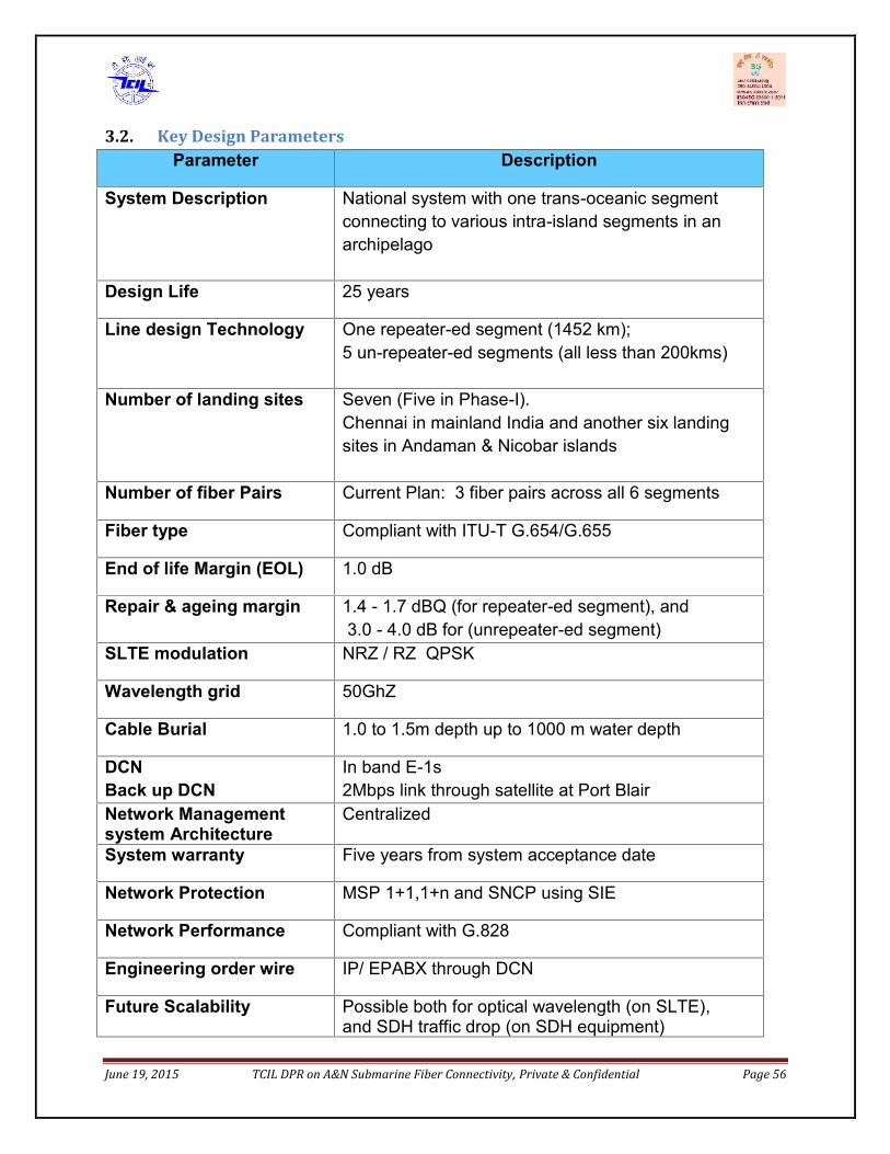
June 19, 2015 TCIL DPR on A&N Submarine Fiber Connectivity, Private & Confidential Page 56
3.2. Key Design ParametersParameter Description
System Description National system with one trans-oceanic segmentconnecting to various intra-island segments in anarchipelago
Design Life 25 years
Line design Technology One repeater-ed segment (1452 km);5 un-repeater-ed segments (all less than 200kms)
Number of landing sites Seven (Five in Phase-I).Chennai in mainland India and another six landingsites in Andaman & Nicobar islands
Number of fiber Pairs Current Plan: 3 fiber pairs across all 6 segments
Fiber type Compliant with ITU-T G.654/G.655
End of life Margin (EOL) 1.0 dB
Repair & ageing margin 1.4 - 1.7 dBQ (for repeater-ed segment), and3.0 - 4.0 dB for (unrepeater-ed segment)
SLTE modulation NRZ / RZ QPSK
Wavelength grid 50GhZ
Cable Burial 1.0 to 1.5m depth up to 1000 m water depth
DCNBack up DCN
In band E-1s2Mbps link through satellite at Port Blair
Network Managementsystem Architecture
Centralized
System warranty Five years from system acceptance date
Network Protection MSP 1+1,1+n and SNCP using SIE
Network Performance Compliant with G.828
Engineering order wire IP/ EPABX through DCN
Future Scalability Possible both for optical wavelength (on SLTE),and SDH traffic drop (on SDH equipment)
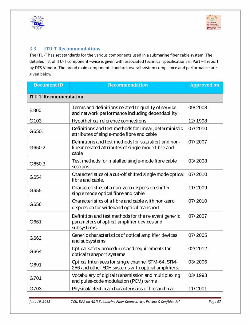
June 19, 2015 TCIL DPR on A&N Submarine Fiber Connectivity, Private & Confidential Page 57
3.3. ITU-T RecommendationsThe ITU-T has set standards for the various components used in a submarine fiber cable system. Thedetailed list of ITU-T component –wise is given with associated technical specifications in Part –II reportby DTS Vendor. The broad main component standard, overall system compliance and performance aregiven below:
Document ID Recommendation Approved on
ITU-T Recommendation
E.800 Terms and definitions related to quality of serviceand network performance including dependability. 09/2008G.103 Hypothetical reference connections 12/1998G.650.1 Definitions and test methods for linear, deterministicattributes of single-mode fibre and cable 07/2010G.650.2 Definitions and test methods for statistical and non-linear related attributes of single-mode fibre andcable 07/2007G.650.3 Test methods for installed single-mode fibre cablesections 03/2008G.654 Characteristics of a cut-off shifted single mode opticalfibre and cable. 07/2010G.655 Characteristics of a non-zero dispersion shiftedsingle mode optical fibre and cable 11/2009G.656 Characteristics of a fibre and cable with non-zerodispersion for wideband optical transport 07/2010G.661 Definition and test methods for the relevant genericparameters of optical amplifier devices andsubsystems. 07/2007G.662 Generic characteristics of optical amplifier devicesand subsystems 07/2005G.664 Optical safety procedures and requirements foroptical transport systems 02/2012G.691 Optical Interfaces for single channel STM-64, STM-256 and other SDH systems with optical amplifiers. 03/2006G.701 Vocabulary of digital transmission and multiplexingand pulse-code modulation (PCM) terms 03/1993G.703 Physical/electrical characteristics of hierarchical 11/2001June 19, 2015 TCIL DPR on A&N Submarine Fiber Connectivity, Private & Confidential Page 57
3.3. ITU-T RecommendationsThe ITU-T has set standards for the various components used in a submarine fiber cable system. Thedetailed list of ITU-T component –wise is given with associated technical specifications in Part –II reportby DTS Vendor. The broad main component standard, overall system compliance and performance aregiven below:
Document ID Recommendation Approved on
ITU-T Recommendation
E.800 Terms and definitions related to quality of serviceand network performance including dependability. 09/2008G.103 Hypothetical reference connections 12/1998G.650.1 Definitions and test methods for linear, deterministicattributes of single-mode fibre and cable 07/2010G.650.2 Definitions and test methods for statistical and non-linear related attributes of single-mode fibre andcable 07/2007G.650.3 Test methods for installed single-mode fibre cablesections 03/2008G.654 Characteristics of a cut-off shifted single mode opticalfibre and cable. 07/2010G.655 Characteristics of a non-zero dispersion shiftedsingle mode optical fibre and cable 11/2009G.656 Characteristics of a fibre and cable with non-zerodispersion for wideband optical transport 07/2010G.661 Definition and test methods for the relevant genericparameters of optical amplifier devices andsubsystems. 07/2007G.662 Generic characteristics of optical amplifier devicesand subsystems 07/2005G.664 Optical safety procedures and requirements foroptical transport systems 02/2012G.691 Optical Interfaces for single channel STM-64, STM-256 and other SDH systems with optical amplifiers. 03/2006G.701 Vocabulary of digital transmission and multiplexingand pulse-code modulation (PCM) terms 03/1993G.703 Physical/electrical characteristics of hierarchical 11/2001
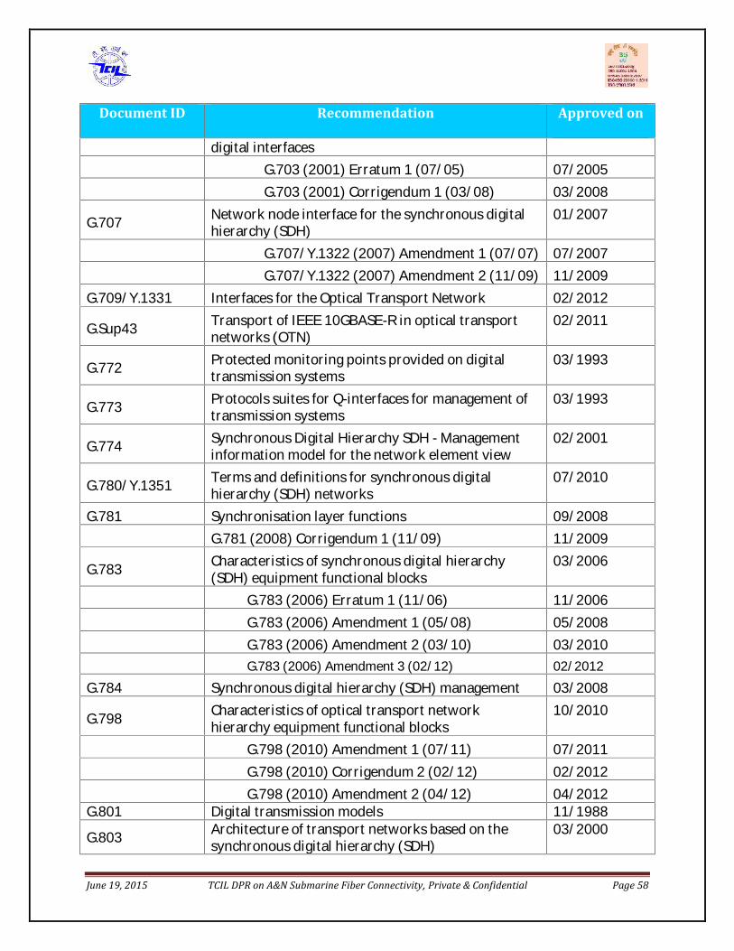
June 19, 2015 TCIL DPR on A&N Submarine Fiber Connectivity, Private & Confidential Page 58
Document ID Recommendation Approved ondigital interfacesG.703 (2001) Erratum 1 (07/05) 07/2005G.703 (2001) Corrigendum 1 (03/08) 03/2008G.707 Network node interface for the synchronous digitalhierarchy (SDH) 01/2007G.707/Y.1322 (2007) Amendment 1 (07/07) 07/2007G.707/Y.1322 (2007) Amendment 2 (11/09) 11/2009G.709/Y.1331 Interfaces for the Optical Transport Network 02/2012G.Sup43 Transport of IEEE 10GBASE-R in optical transportnetworks (OTN) 02/2011G.772 Protected monitoring points provided on digitaltransmission systems 03/1993G.773 Protocols suites for Q-interfaces for management oftransmission systems 03/1993G.774 Synchronous Digital Hierarchy SDH - Managementinformation model for the network element view 02/2001G.780/Y.1351 Terms and definitions for synchronous digitalhierarchy (SDH) networks 07/2010G.781 Synchronisation layer functions 09/2008G.781 (2008) Corrigendum 1 (11/09) 11/2009G.783 Characteristics of synchronous digital hierarchy(SDH) equipment functional blocks 03/2006G.783 (2006) Erratum 1 (11/06) 11/2006G.783 (2006) Amendment 1 (05/08) 05/2008G.783 (2006) Amendment 2 (03/10) 03/2010G.783 (2006) Amendment 3 (02/12) 02/2012G.784 Synchronous digital hierarchy (SDH) management 03/2008G.798 Characteristics of optical transport networkhierarchy equipment functional blocks 10/2010G.798 (2010) Amendment 1 (07/11) 07/2011G.798 (2010) Corrigendum 2 (02/12) 02/2012G.798 (2010) Amendment 2 (04/12) 04/2012G.801 Digital transmission models 11/1988G.803 Architecture of transport networks based on thesynchronous digital hierarchy (SDH) 03/2000June 19, 2015 TCIL DPR on A&N Submarine Fiber Connectivity, Private & Confidential Page 58
Document ID Recommendation Approved ondigital interfacesG.703 (2001) Erratum 1 (07/05) 07/2005G.703 (2001) Corrigendum 1 (03/08) 03/2008G.707 Network node interface for the synchronous digitalhierarchy (SDH) 01/2007G.707/Y.1322 (2007) Amendment 1 (07/07) 07/2007G.707/Y.1322 (2007) Amendment 2 (11/09) 11/2009G.709/Y.1331 Interfaces for the Optical Transport Network 02/2012G.Sup43 Transport of IEEE 10GBASE-R in optical transportnetworks (OTN) 02/2011G.772 Protected monitoring points provided on digitaltransmission systems 03/1993G.773 Protocols suites for Q-interfaces for management oftransmission systems 03/1993G.774 Synchronous Digital Hierarchy SDH - Managementinformation model for the network element view 02/2001G.780/Y.1351 Terms and definitions for synchronous digitalhierarchy (SDH) networks 07/2010G.781 Synchronisation layer functions 09/2008G.781 (2008) Corrigendum 1 (11/09) 11/2009G.783 Characteristics of synchronous digital hierarchy(SDH) equipment functional blocks 03/2006G.783 (2006) Erratum 1 (11/06) 11/2006G.783 (2006) Amendment 1 (05/08) 05/2008G.783 (2006) Amendment 2 (03/10) 03/2010G.783 (2006) Amendment 3 (02/12) 02/2012G.784 Synchronous digital hierarchy (SDH) management 03/2008G.798 Characteristics of optical transport networkhierarchy equipment functional blocks 10/2010G.798 (2010) Amendment 1 (07/11) 07/2011G.798 (2010) Corrigendum 2 (02/12) 02/2012G.798 (2010) Amendment 2 (04/12) 04/2012G.801 Digital transmission models 11/1988G.803 Architecture of transport networks based on thesynchronous digital hierarchy (SDH) 03/2000June 19, 2015 TCIL DPR on A&N Submarine Fiber Connectivity, Private & Confidential Page 58
Document ID Recommendation Approved ondigital interfacesG.703 (2001) Erratum 1 (07/05) 07/2005G.703 (2001) Corrigendum 1 (03/08) 03/2008G.707 Network node interface for the synchronous digitalhierarchy (SDH) 01/2007G.707/Y.1322 (2007) Amendment 1 (07/07) 07/2007G.707/Y.1322 (2007) Amendment 2 (11/09) 11/2009G.709/Y.1331 Interfaces for the Optical Transport Network 02/2012G.Sup43 Transport of IEEE 10GBASE-R in optical transportnetworks (OTN) 02/2011G.772 Protected monitoring points provided on digitaltransmission systems 03/1993G.773 Protocols suites for Q-interfaces for management oftransmission systems 03/1993G.774 Synchronous Digital Hierarchy SDH - Managementinformation model for the network element view 02/2001G.780/Y.1351 Terms and definitions for synchronous digitalhierarchy (SDH) networks 07/2010G.781 Synchronisation layer functions 09/2008G.781 (2008) Corrigendum 1 (11/09) 11/2009G.783 Characteristics of synchronous digital hierarchy(SDH) equipment functional blocks 03/2006G.783 (2006) Erratum 1 (11/06) 11/2006G.783 (2006) Amendment 1 (05/08) 05/2008G.783 (2006) Amendment 2 (03/10) 03/2010G.783 (2006) Amendment 3 (02/12) 02/2012G.784 Synchronous digital hierarchy (SDH) management 03/2008G.798 Characteristics of optical transport networkhierarchy equipment functional blocks 10/2010G.798 (2010) Amendment 1 (07/11) 07/2011G.798 (2010) Corrigendum 2 (02/12) 02/2012G.798 (2010) Amendment 2 (04/12) 04/2012G.801 Digital transmission models 11/1988G.803 Architecture of transport networks based on thesynchronous digital hierarchy (SDH) 03/2000
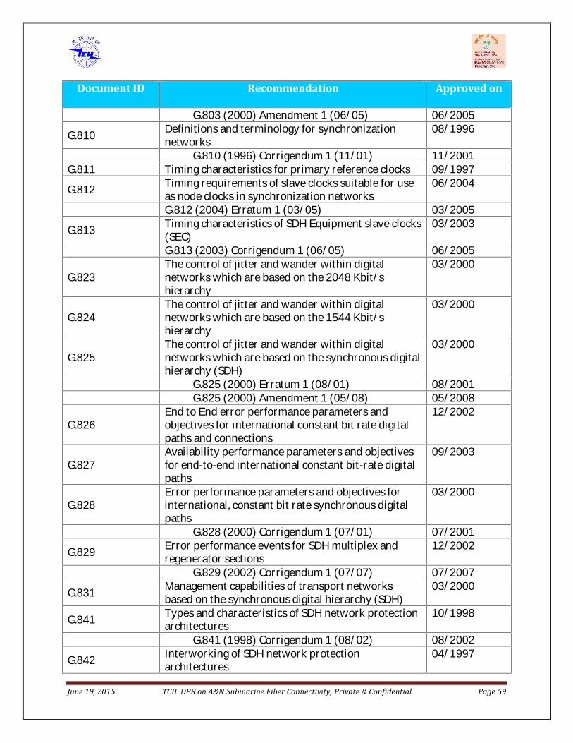
June 19, 2015 TCIL DPR on A&N Submarine Fiber Connectivity, Private & Confidential Page 59
Document ID Recommendation Approved onG.803 (2000) Amendment 1 (06/05) 06/2005G.810 Definitions and terminology for synchronizationnetworks 08/1996G.810 (1996) Corrigendum 1 (11/01) 11/2001G.811 Timing characteristics for primary reference clocks 09/1997G.812 Timing requirements of slave clocks suitable for useas node clocks in synchronization networks 06/2004G.812 (2004) Erratum 1 (03/05) 03/2005G.813 Timing characteristics of SDH Equipment slave clocks(SEC) 03/2003G.813 (2003) Corrigendum 1 (06/05) 06/2005G.823 The control of jitter and wander within digitalnetworks which are based on the 2048 Kbit/shierarchy 03/2000G.824 The control of jitter and wander within digitalnetworks which are based on the 1544 Kbit/shierarchy 03/2000G.825 The control of jitter and wander within digitalnetworks which are based on the synchronous digitalhierarchy (SDH) 03/2000
G.825 (2000) Erratum 1 (08/01) 08/2001G.825 (2000) Amendment 1 (05/08) 05/2008G.826 End to End error performance parameters andobjectives for international constant bit rate digitalpaths and connections 12/2002G.827 Availability performance parameters and objectivesfor end-to-end international constant bit-rate digitalpaths 09/2003G.828 Error performance parameters and objectives forinternational, constant bit rate synchronous digitalpaths 03/2000
G.828 (2000) Corrigendum 1 (07/01) 07/2001G.829 Error performance events for SDH multiplex andregenerator sections 12/2002G.829 (2002) Corrigendum 1 (07/07) 07/2007G.831 Management capabilities of transport networksbased on the synchronous digital hierarchy (SDH) 03/2000G.841 Types and characteristics of SDH network protectionarchitectures 10/1998G.841 (1998) Corrigendum 1 (08/02) 08/2002G.842 Interworking of SDH network protectionarchitectures 04/1997June 19, 2015 TCIL DPR on A&N Submarine Fiber Connectivity, Private & Confidential Page 59
Document ID Recommendation Approved onG.803 (2000) Amendment 1 (06/05) 06/2005G.810 Definitions and terminology for synchronizationnetworks 08/1996G.810 (1996) Corrigendum 1 (11/01) 11/2001G.811 Timing characteristics for primary reference clocks 09/1997G.812 Timing requirements of slave clocks suitable for useas node clocks in synchronization networks 06/2004G.812 (2004) Erratum 1 (03/05) 03/2005G.813 Timing characteristics of SDH Equipment slave clocks(SEC) 03/2003G.813 (2003) Corrigendum 1 (06/05) 06/2005G.823 The control of jitter and wander within digitalnetworks which are based on the 2048 Kbit/shierarchy 03/2000G.824 The control of jitter and wander within digitalnetworks which are based on the 1544 Kbit/shierarchy 03/2000G.825 The control of jitter and wander within digitalnetworks which are based on the synchronous digitalhierarchy (SDH) 03/2000
G.825 (2000) Erratum 1 (08/01) 08/2001G.825 (2000) Amendment 1 (05/08) 05/2008G.826 End to End error performance parameters andobjectives for international constant bit rate digitalpaths and connections 12/2002G.827 Availability performance parameters and objectivesfor end-to-end international constant bit-rate digitalpaths 09/2003G.828 Error performance parameters and objectives forinternational, constant bit rate synchronous digitalpaths 03/2000
G.828 (2000) Corrigendum 1 (07/01) 07/2001G.829 Error performance events for SDH multiplex andregenerator sections 12/2002G.829 (2002) Corrigendum 1 (07/07) 07/2007G.831 Management capabilities of transport networksbased on the synchronous digital hierarchy (SDH) 03/2000G.841 Types and characteristics of SDH network protectionarchitectures 10/1998G.841 (1998) Corrigendum 1 (08/02) 08/2002G.842 Interworking of SDH network protectionarchitectures 04/1997

June 19, 2015 TCIL DPR on A&N Submarine Fiber Connectivity, Private & Confidential Page 60
Document ID Recommendation Approved on
G.870 Terms and definitions for Optical TransportNetworks (OTN) 02/2012G.871 Framework of optical transport networkRecommendations 10/2000G.872 Architecture of optical transport networks 11/2001G.872 (2001) Amendment 1 (12/03) 12/2003G.872 (2001) Corrigendum 1 (01/05) 01/2005G.872 (2001) Amendment 2 (07/10) 07/2010G.873.1 Optical Transport Network (OTN): Linear protectionG.911 Parameters and calculation methodologies forreliability and availability of fibre optic systems 04/1997G.957 Optical interfaces for equipment and systems relatingto the synchronous digital hierarchy 03/2006G.959.1 Optical transport network physical layer interfaces 02/2012G.971 General features of optical fibre submarine cablesystems 07/2010G.972 Definition of terms relevant to optical fibresubmarine cable systems 09/2011G.973 Characteristics of repeater-less optical fibresubmarine cable systems 07/2010G.975 Forward error correction for submarine systems 10/2000G.975.1 Forward error correction for high bit rate DWDMsubmarine systems 02/2004G.975.1 (2004) Corrigendum 1 (02/06) 02/2006G.976 Test methods applicable to optical fibre cablesystems 07/2010G.977 Characteristics of optically amplified optical fibresubmarine cable systems 04/2011G.978 Characteristics of optical fibre submarine cables 07/2010M.2101 Performance limits and objectives for bringing intoservice and maintenance of international SDH pathsand multiplex sections 06/2003M.2110 Bringing into service international multi-operatorpaths, sections and transmission systems 07/2002M.2120 International multi-operator paths, sections andtransmission systems fault detection and localisationprocedures. 07/2002M.3010 Principles for a telecommunication managementnetwork 02/2000M.3010 (2000) Amendment 1 (12/03), TMNconformance and TMN compliance 12/2003M.3010 (2000) Amendment 2 (11/05), 11/2005June 19, 2015 TCIL DPR on A&N Submarine Fiber Connectivity, Private & Confidential Page 60
Document ID Recommendation Approved on
G.870 Terms and definitions for Optical TransportNetworks (OTN) 02/2012G.871 Framework of optical transport networkRecommendations 10/2000G.872 Architecture of optical transport networks 11/2001G.872 (2001) Amendment 1 (12/03) 12/2003G.872 (2001) Corrigendum 1 (01/05) 01/2005G.872 (2001) Amendment 2 (07/10) 07/2010G.873.1 Optical Transport Network (OTN): Linear protectionG.911 Parameters and calculation methodologies forreliability and availability of fibre optic systems 04/1997G.957 Optical interfaces for equipment and systems relatingto the synchronous digital hierarchy 03/2006G.959.1 Optical transport network physical layer interfaces 02/2012G.971 General features of optical fibre submarine cablesystems 07/2010G.972 Definition of terms relevant to optical fibresubmarine cable systems 09/2011G.973 Characteristics of repeater-less optical fibresubmarine cable systems 07/2010G.975 Forward error correction for submarine systems 10/2000G.975.1 Forward error correction for high bit rate DWDMsubmarine systems 02/2004G.975.1 (2004) Corrigendum 1 (02/06) 02/2006G.976 Test methods applicable to optical fibre cablesystems 07/2010G.977 Characteristics of optically amplified optical fibresubmarine cable systems 04/2011G.978 Characteristics of optical fibre submarine cables 07/2010M.2101 Performance limits and objectives for bringing intoservice and maintenance of international SDH pathsand multiplex sections 06/2003M.2110 Bringing into service international multi-operatorpaths, sections and transmission systems 07/2002M.2120 International multi-operator paths, sections andtransmission systems fault detection and localisationprocedures. 07/2002M.3010 Principles for a telecommunication managementnetwork 02/2000M.3010 (2000) Amendment 1 (12/03), TMNconformance and TMN compliance 12/2003M.3010 (2000) Amendment 2 (11/05), 11/2005
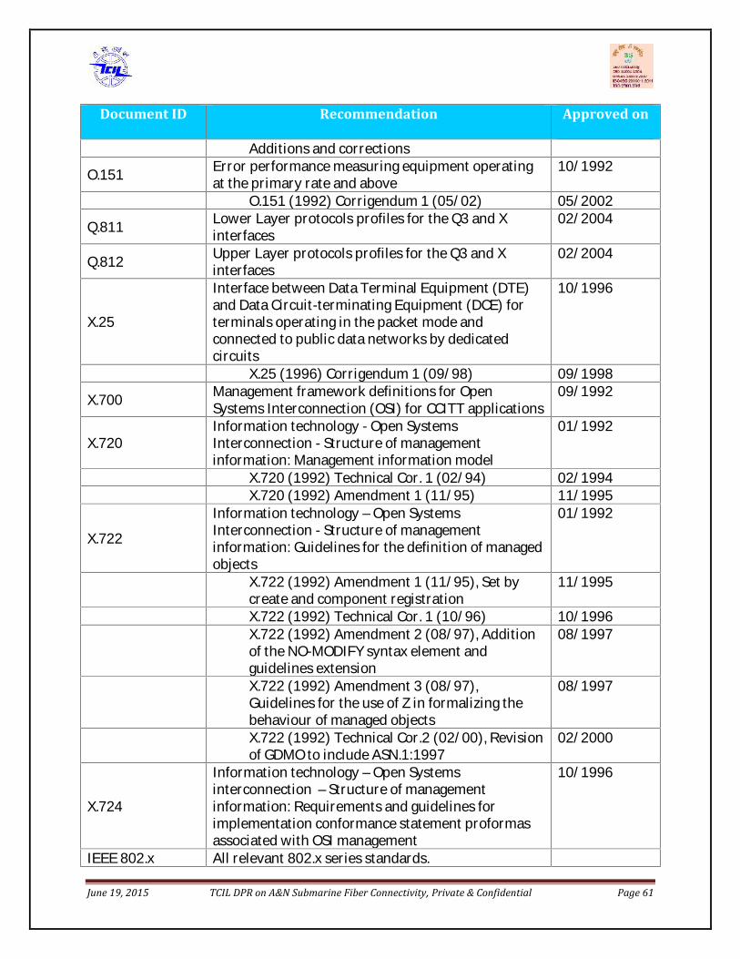
June 19, 2015 TCIL DPR on A&N Submarine Fiber Connectivity, Private & Confidential Page 61
Document ID Recommendation Approved onAdditions and correctionsO.151 Error performance measuring equipment operatingat the primary rate and above 10/1992O.151 (1992) Corrigendum 1 (05/02) 05/2002Q.811 Lower Layer protocols profiles for the Q3 and Xinterfaces 02/2004Q.812 Upper Layer protocols profiles for the Q3 and Xinterfaces 02/2004X.25 Interface between Data Terminal Equipment (DTE)and Data Circuit-terminating Equipment (DCE) forterminals operating in the packet mode andconnected to public data networks by dedicatedcircuits
10/1996X.25 (1996) Corrigendum 1 (09/98) 09/1998X.700 Management framework definitions for OpenSystems Interconnection (OSI) for CCITT applications 09/1992
X.720 Information technology - Open SystemsInterconnection - Structure of managementinformation: Management information model 01/1992X.720 (1992) Technical Cor. 1 (02/94) 02/1994X.720 (1992) Amendment 1 (11/95) 11/1995
X.722 Information technology – Open SystemsInterconnection - Structure of managementinformation: Guidelines for the definition of managedobjects01/1992
X.722 (1992) Amendment 1 (11/95), Set bycreate and component registration 11/1995X.722 (1992) Technical Cor. 1 (10/96) 10/1996X.722 (1992) Amendment 2 (08/97), Additionof the NO-MODIFY syntax element andguidelines extension 08/1997X.722 (1992) Amendment 3 (08/97),Guidelines for the use of Z in formalizing thebehaviour of managed objects 08/1997X.722 (1992) Technical Cor.2 (02/00), Revisionof GDMO to include ASN.1:1997 02/2000
X.724 Information technology – Open Systemsinterconnection – Structure of managementinformation: Requirements and guidelines forimplementation conformance statement proformasassociated with OSI management10/1996
IEEE 802.x All relevant 802.x series standards.June 19, 2015 TCIL DPR on A&N Submarine Fiber Connectivity, Private & Confidential Page 61
Document ID Recommendation Approved onAdditions and correctionsO.151 Error performance measuring equipment operatingat the primary rate and above 10/1992O.151 (1992) Corrigendum 1 (05/02) 05/2002Q.811 Lower Layer protocols profiles for the Q3 and Xinterfaces 02/2004Q.812 Upper Layer protocols profiles for the Q3 and Xinterfaces 02/2004X.25 Interface between Data Terminal Equipment (DTE)and Data Circuit-terminating Equipment (DCE) forterminals operating in the packet mode andconnected to public data networks by dedicatedcircuits
10/1996X.25 (1996) Corrigendum 1 (09/98) 09/1998X.700 Management framework definitions for OpenSystems Interconnection (OSI) for CCITT applications 09/1992
X.720 Information technology - Open SystemsInterconnection - Structure of managementinformation: Management information model 01/1992X.720 (1992) Technical Cor. 1 (02/94) 02/1994X.720 (1992) Amendment 1 (11/95) 11/1995
X.722 Information technology – Open SystemsInterconnection - Structure of managementinformation: Guidelines for the definition of managedobjects01/1992
X.722 (1992) Amendment 1 (11/95), Set bycreate and component registration 11/1995X.722 (1992) Technical Cor. 1 (10/96) 10/1996X.722 (1992) Amendment 2 (08/97), Additionof the NO-MODIFY syntax element andguidelines extension 08/1997X.722 (1992) Amendment 3 (08/97),Guidelines for the use of Z in formalizing thebehaviour of managed objects 08/1997X.722 (1992) Technical Cor.2 (02/00), Revisionof GDMO to include ASN.1:1997 02/2000
X.724 Information technology – Open Systemsinterconnection – Structure of managementinformation: Requirements and guidelines forimplementation conformance statement proformasassociated with OSI management10/1996
IEEE 802.x All relevant 802.x series standards.

June 19, 2015 TCIL DPR on A&N Submarine Fiber Connectivity, Private & Confidential Page 62
Document ID Recommendation Approved on
ETSI RECOMMENDATIONSETS 300019 Equipment Engineering: Environmental conditionsand environmental tests for telecommunicationsequipmentETS 300119 European Telecommunication Standards forEquipment PracticeETS 300132 Power supply interface at the inputtelecommunications equipmentETS 300 253 Earthing and bonding of telecommunicationequipment intelecommunication centresETS 300386 Public Telecommunication Network Equipment –Electro-Magnetic Compatibility RequirementsIEC STANDARDSIEC 60297 Specification for Dimension of Panels and Racks forElectronic EquipmentIEC 60617 Graphical Symbols for Electrical and ElectronicDiagramsIEC 60721-2-x Classification of environmental conditionsIEC 60825 Safety of laser products, equipment classificationrequirements and users guideIEC 60950-1 Information Technology EquipmentIEC 60950-21 Safety: General RequirementsIEC 61000-4-x Electromagnetic Compatibility (EMC) Parts 4-2 (Apr.2001), 4-3 (Sept. 2002), 4-4 (Mar. 2002), 4-5 (Apr.2001), 4-6 (May 2003)IEC 61000-4-x Electromagnetic compatibility for informationtechnology, multimedia equipment and receivers:Radiated and Conducted Emissions from InformationTechnology EquipmentISO STANDARDSISO 8402 Quality management and quality assurance.VocabularyISO 9001 Quality Management Systems - RequirementsISO 9004 Quality Management Systems – Part O: Guide toQuality Management and Quality System ElementsTL 9000-H,-S,-V
TL9000 - Quality Management System:- Requirement Handbook Release 3.0- Measurement Handbook Release 3.5June 19, 2015 TCIL DPR on A&N Submarine Fiber Connectivity, Private & Confidential Page 62
Document ID Recommendation Approved on
ETSI RECOMMENDATIONSETS 300019 Equipment Engineering: Environmental conditionsand environmental tests for telecommunicationsequipmentETS 300119 European Telecommunication Standards forEquipment PracticeETS 300132 Power supply interface at the inputtelecommunications equipmentETS 300 253 Earthing and bonding of telecommunicationequipment intelecommunication centresETS 300386 Public Telecommunication Network Equipment –Electro-Magnetic Compatibility RequirementsIEC STANDARDSIEC 60297 Specification for Dimension of Panels and Racks forElectronic EquipmentIEC 60617 Graphical Symbols for Electrical and ElectronicDiagramsIEC 60721-2-x Classification of environmental conditionsIEC 60825 Safety of laser products, equipment classificationrequirements and users guideIEC 60950-1 Information Technology EquipmentIEC 60950-21 Safety: General RequirementsIEC 61000-4-x Electromagnetic Compatibility (EMC) Parts 4-2 (Apr.2001), 4-3 (Sept. 2002), 4-4 (Mar. 2002), 4-5 (Apr.2001), 4-6 (May 2003)IEC 61000-4-x Electromagnetic compatibility for informationtechnology, multimedia equipment and receivers:Radiated and Conducted Emissions from InformationTechnology EquipmentISO STANDARDSISO 8402 Quality management and quality assurance.VocabularyISO 9001 Quality Management Systems - RequirementsISO 9004 Quality Management Systems – Part O: Guide toQuality Management and Quality System ElementsTL 9000-H,-S,-V
TL9000 - Quality Management System:- Requirement Handbook Release 3.0- Measurement Handbook Release 3.5
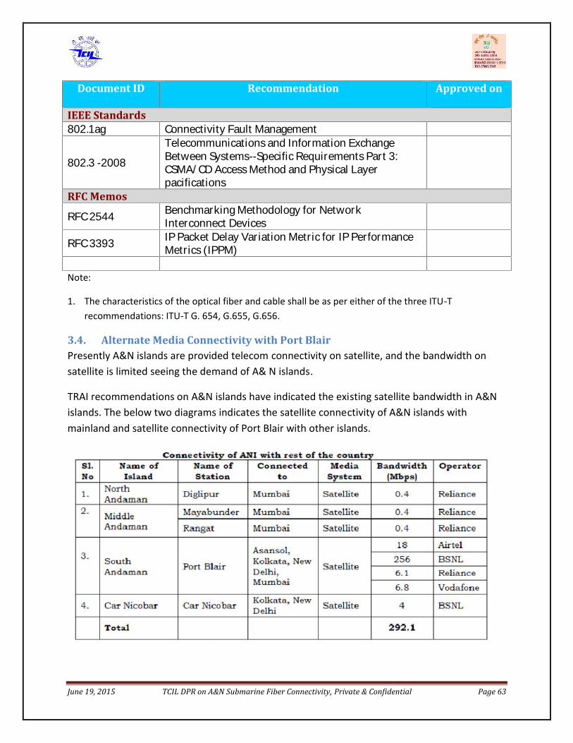
June 19, 2015 TCIL DPR on A&N Submarine Fiber Connectivity, Private & Confidential Page 63
Document ID Recommendation Approved on
IEEE Standards802.1ag Connectivity Fault Management802.3 -2008 Telecommunications and Information ExchangeBetween Systems--Specific Requirements Part 3:CSMA/CD Access Method and Physical LayerpacificationsRFC MemosRFC 2544 Benchmarking Methodology for NetworkInterconnect DevicesRFC 3393 IP Packet Delay Variation Metric for IP PerformanceMetrics (IPPM)Note:
1. The characteristics of the optical fiber and cable shall be as per either of the three ITU-Trecommendations: ITU-T G. 654, G.655, G.656.
3.4. Alternate Media Connectivity with Port BlairPresently A&N islands are provided telecom connectivity on satellite, and the bandwidth onsatellite is limited seeing the demand of A& N islands.
TRAI recommendations on A&N islands have indicated the existing satellite bandwidth in A&Nislands. The below two diagrams indicates the satellite connectivity of A&N islands withmainland and satellite connectivity of Port Blair with other islands.

June 19, 2015 TCIL DPR on A&N Submarine Fiber Connectivity, Private & Confidential Page 64
There are 29 inhabited islands in A&N and , among these islands the six islands shall beprovided direct submarine fiber connectivity which shall cover more than 90% population.There are 10 remaining islands with substantial population, 5 of which are connected onsatellite and remaining have no satellite connectivity. The statistics given above is based on thedata given in TRAI recommendations and also shown below:
As the submarine cable project shall take time to execute , it was felt that existing satellitebandwidth should be upgraded. This assignment has been given to BSNL in a recent meetingtaken up by Secretary (T).
Once the A&N islands are provided submarine fiber connectivity, the present bandwidthengaged on satellite for telecom connectivity could be released. However, satellite can still act
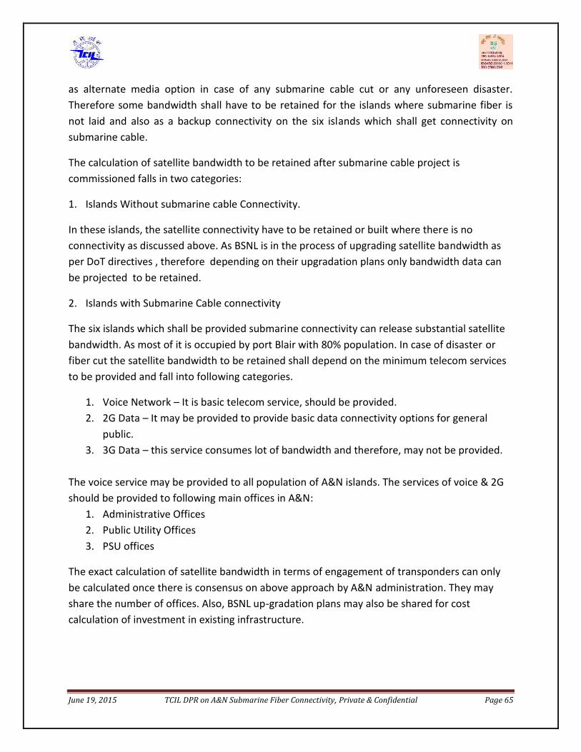
June 19, 2015 TCIL DPR on A&N Submarine Fiber Connectivity, Private & Confidential Page 65
as alternate media option in case of any submarine cable cut or any unforeseen disaster.Therefore some bandwidth shall have to be retained for the islands where submarine fiber isnot laid and also as a backup connectivity on the six islands which shall get connectivity onsubmarine cable.
The calculation of satellite bandwidth to be retained after submarine cable project iscommissioned falls in two categories:
1. Islands Without submarine cable Connectivity.
In these islands, the satellite connectivity have to be retained or built where there is noconnectivity as discussed above. As BSNL is in the process of upgrading satellite bandwidth asper DoT directives , therefore depending on their upgradation plans only bandwidth data canbe projected to be retained.
2. Islands with Submarine Cable connectivity
The six islands which shall be provided submarine connectivity can release substantial satellitebandwidth. As most of it is occupied by port Blair with 80% population. In case of disaster orfiber cut the satellite bandwidth to be retained shall depend on the minimum telecom servicesto be provided and fall into following categories.
1. Voice Network – It is basic telecom service, should be provided.2. 2G Data – It may be provided to provide basic data connectivity options for general
public.3. 3G Data – this service consumes lot of bandwidth and therefore, may not be provided.
The voice service may be provided to all population of A&N islands. The services of voice & 2Gshould be provided to following main offices in A&N:
1. Administrative Offices2. Public Utility Offices3. PSU offices
The exact calculation of satellite bandwidth in terms of engagement of transponders can onlybe calculated once there is consensus on above approach by A&N administration. They mayshare the number of offices. Also, BSNL up-gradation plans may also be shared for costcalculation of investment in existing infrastructure.
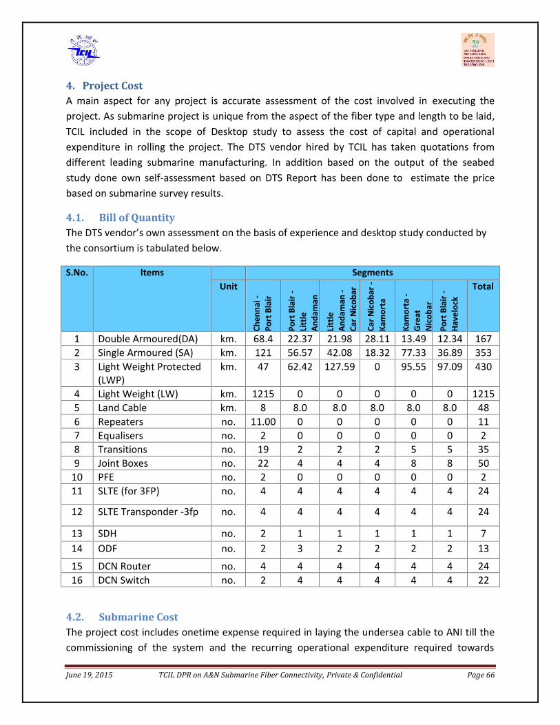
June 19, 2015 TCIL DPR on A&N Submarine Fiber Connectivity, Private & Confidential Page 66
4. Project CostA main aspect for any project is accurate assessment of the cost involved in executing theproject. As submarine project is unique from the aspect of the fiber type and length to be laid,TCIL included in the scope of Desktop study to assess the cost of capital and operationalexpenditure in rolling the project. The DTS vendor hired by TCIL has taken quotations fromdifferent leading submarine manufacturing. In addition based on the output of the seabedstudy done own self-assessment based on DTS Report has been done to estimate the pricebased on submarine survey results.
4.1. Bill of QuantityThe DTS vendor’s own assessment on the basis of experience and desktop study conducted bythe consortium is tabulated below.
S.No. Items SegmentsUnit
Chen
nai-
Port
Bla
ir
Port
Bla
ir-
Litt
leAn
dam
an
Litt
leAn
dam
an-
Car N
icob
ar
Car N
icob
ar-
Kam
orta
Kam
orta
-Gr
eat
Nic
obar
Port
Bla
ir-
Have
lock
Total
1 Double Armoured(DA) km. 68.4 22.37 21.98 28.11 13.49 12.34 1672 Single Armoured (SA) km. 121 56.57 42.08 18.32 77.33 36.89 3533 Light Weight Protected
(LWP)km. 47 62.42 127.59 0 95.55 97.09 430
4 Light Weight (LW) km. 1215 0 0 0 0 0 12155 Land Cable km. 8 8.0 8.0 8.0 8.0 8.0 486 Repeaters no. 11.00 0 0 0 0 0 117 Equalisers no. 2 0 0 0 0 0 28 Transitions no. 19 2 2 2 5 5 359 Joint Boxes no. 22 4 4 4 8 8 50
10 PFE no. 2 0 0 0 0 0 211 SLTE (for 3FP) no. 4 4 4 4 4 4 24
12 SLTE Transponder -3fp no. 4 4 4 4 4 4 24
13 SDH no. 2 1 1 1 1 1 714 ODF no. 2 3 2 2 2 2 13
15 DCN Router no. 4 4 4 4 4 4 2416 DCN Switch no. 2 4 4 4 4 4 22
4.2. Submarine CostThe project cost includes onetime expense required in laying the undersea cable to ANI till thecommissioning of the system and the recurring operational expenditure required towards
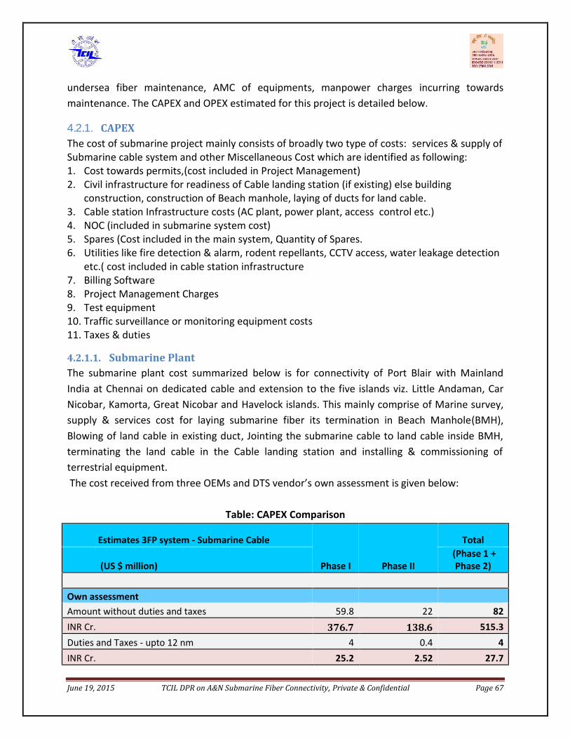
June 19, 2015 TCIL DPR on A&N Submarine Fiber Connectivity, Private & Confidential Page 67
undersea fiber maintenance, AMC of equipments, manpower charges incurring towardsmaintenance. The CAPEX and OPEX estimated for this project is detailed below.4.2.1. CAPEXThe cost of submarine project mainly consists of broadly two type of costs: services & supply ofSubmarine cable system and other Miscellaneous Cost which are identified as following:1. Cost towards permits,(cost included in Project Management)2. Civil infrastructure for readiness of Cable landing station (if existing) else building
construction, construction of Beach manhole, laying of ducts for land cable.3. Cable station Infrastructure costs (AC plant, power plant, access control etc.)4. NOC (included in submarine system cost)5. Spares (Cost included in the main system, Quantity of Spares.6. Utilities like fire detection & alarm, rodent repellants, CCTV access, water leakage detection
etc.( cost included in cable station infrastructure7. Billing Software8. Project Management Charges9. Test equipment10. Traffic surveillance or monitoring equipment costs11. Taxes & duties
4.2.1.1. Submarine PlantThe submarine plant cost summarized below is for connectivity of Port Blair with MainlandIndia at Chennai on dedicated cable and extension to the five islands viz. Little Andaman, CarNicobar, Kamorta, Great Nicobar and Havelock islands. This mainly comprise of Marine survey,supply & services cost for laying submarine fiber its termination in Beach Manhole(BMH),Blowing of land cable in existing duct, Jointing the submarine cable to land cable inside BMH,terminating the land cable in the Cable landing station and installing & commissioning ofterrestrial equipment.The cost received from three OEMs and DTS vendor’s own assessment is given below:
Table: CAPEX Comparison
Estimates 3FP system - Submarine Cable
Phase I Phase II
Total
(US $ million)(Phase 1 +Phase 2)
Own assessmentAmount without duties and taxes 59.8 22 82INR Cr. 376.7 138.6 515.3Duties and Taxes - upto 12 nm 4 0.4 4INR Cr. 25.2 2.52 27.7

June 19, 2015 TCIL DPR on A&N Submarine Fiber Connectivity, Private & Confidential Page 68
Duties and Taxes - up to 200 nm 10.8 1.5 12INR Cr. 68 9.4 75.6Scenario 1: Total with Duties and Taxes - 12 nm 63.8 22.5 86INR Cr. 401.9 141.75 541.8Scenario 2: Total with Duties and - 200 nm 70.6 23.5 94INR Cr. 444.7 148.1 592.2
Quotation1Amount without duties and taxes 70.1 35.6 106INR Cr. 441.6 224.3 667.8Duties and Taxes 14.2 5 19INR Cr. 89.5 31.5 119.7Total with Duties and Taxes 84.3 40.6 125INR Cr. 531 255.8 787.5Quotation2Amount without duties and taxes 72.7 30.9 104INR Cr. 458 194.7 655.2Duties and Taxes 6.8 4.3 11INR Cr. 42.8 27.1 69.3Total with Duties and Taxes 79.5 35.2 115INR Cr. 500.8 221.7 724.5Quotation3Amount without duties and taxes 67
Did not provide
67INR Cr. 422.1 422.1Duties and Taxes 3 3
18.9 18.9Total with Duties and Taxes 70.1 70INR Cr. 441.6 441(Conversion rate taken 1 USD=63 INR)
4.2.1.2. Other CAPEX HeadsThe other cost elements that are important to be considered for the CAPEX budgeting of asubmarine cable project are;
a) Civil infrastructure costs (BMH, land ducts and Cable station up-liftment)For budgeting, BMH and land routes are considered as entire greenfield constructions. It isassumed though that cable landing station space is available at all locations and some degree ofcivil up-liftment would be needed to make them ready for receiving equipment and cable (likeduct and chut construction, earthing, painting, leakage proofing, flooring etc).
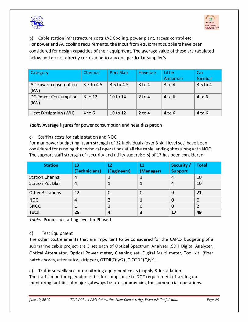
June 19, 2015 TCIL DPR on A&N Submarine Fiber Connectivity, Private & Confidential Page 69
b) Cable station infrastructure costs (AC Cooling, power plant, access control etc)For power and AC cooling requirements, the input from equipment suppliers have beenconsidered for design capacities of their equipment. The average value of these are tabulatedbelow and do not directly correspond to any one particular supplier’s
Table: Average figures for power consumption and heat dissipation
c) Staffing costs for cable station and NOCFor manpower budgeting, team strength of 32 individuals (over 3 skill level set) have beenconsidered for running the technical operations at all the cable landing sites along with NOC.The support staff strength of (security and utility supervisors) of 17 has been considered.
Station L3(Technicians)
L2(Engineers)
L1(Manager)
Security /Support
Total
Station Chennai 4 1 1 4 10Station Pot Blair 4 1 1 4 10
Other 3 stations 12 0 0 9 21NOC 4 2 1 0 6BNOC 1 1 0 0 2Total 25 4 3 17 49Table: Proposed staffing level for Phase-I
d) Test EquipmentThe other cost elements that are important to be considered for the CAPEX budgeting of asubmarine cable project are 5 set each of Optical Spectrum Analyzer ,SDH Digital Analyzer,Optical Attenuator, Optical Power meter, Cleaning set, Digital Multi meter, Tool kit (fiberpatch chords, attenuator, stripper), OTDR(Qty:2) ,C-OTDR(Qty:1)
e) Traffic surveillance or monitoring equipment costs (supply & Installation)The traffic monitoring equipment is for compliance to DOT requirement of setting upmonitoring facilities at major gateways before commencing the commercial operations.
Category Chennai Port Blair Havelock LittleAndaman
CarNicobar
AC Power consumption(kW)
3.5 to 4.5 3.5 to 4.5 3 to 4 3 to 4 3.5 to 4
DC Power Consumption(kW)
8 to 12 10 to 14 2 to 4 4 to 6 4 to 6
Heat Dissipation (WH) 4 to 6 10 to 12 2 to 4 4 to 6 4 to 6

June 19, 2015 TCIL DPR on A&N Submarine Fiber Connectivity, Private & Confidential Page 70
Since other telecom operators would be using the infrastructure and can have internationaltraffic, hence considering the strategic importance of this telecom infrastructure, provisionfor traffic monitoring equipment has been made.
There are limited suppliers, which provide the monitoring equipment and would need to beseparately contracted. The monitoring network planning would be done once the cablenetwork design is finalized and traffic add-drop points and rates are frozen. Hence a lumpsum estimated amount has been provisioned in the CAPEX.
f) Project Management costs (from tendering till system commissioning)The project management would include all activities described in Chapter-8 and would haveengagement of specific professionals, site supervisors and several technical visits . The PMCshall be required through the project cycle must be made. These would include: design reviews,technology demonstration sign-off, factory acceptance sign-off, marine representatives forsurvey & main lay, segment and end to end commissioning testing etc, deficiency clearance andmanagement etc.)
OTHER CAPEX - COST SUMMARY
An estimation for these cost elements for all landings sites of Phase-I of the Andaman cablesystem is tabulated below;
CAPEX Elements Cost(M USD)
Civil infrastructure costs(Cable station up-liftment, land ducts,BMH including ROW ) 1.5
Cable station infrastructure costs (AC Cooling, power plant, access control etc) 1.2Manpower costs for cable station and NOC 0.5Test equipment costs 0.4Traffic surveillance or monitoring equipment costs (supply & Installation) 1.4Total CAPEX (For all landing sites) 5.0
Table-: Break down of Other CAPEX Items
4.2.1.3. Applicability of Customs DutyThe extent of customs duties and taxes in submarine cable projects remains a grey area.Most projects have been taxed up to 12 nautical miles in line with international norms andin line with UNCLOS to which India is a signatory.
However, in the last 5 to 6 years there have been a few projects that have been taxed up to200 nautical miles i.e. up to the Indian EEZ boundary as that is the Indian customs notifiedboundary. The projects that have been taxed up to 200 nm, have paid the duties and taxes,

June 19, 2015 TCIL DPR on A&N Submarine Fiber Connectivity, Private & Confidential Page 71
but the matter is under protest and litigation.
From our experience, even expert opinion seems divided on this issue and differentprecedents and cases are used to justify the stance taken in this matter. Accordingly, anestimate of duties and taxes for both cases i.e. up to 12 nm and up to 200nm is included forreference. Expert legal and customs opinion needs to be sought on this issue from bothIndian Customs as well as an independent expert body and proceed with caution. Needlessto say, a conservative approach should consider duties and taxes up to 200nm and anaggressive approach should consider duties and taxes up to 12 nm.
4.2.1.4. TOTAL CAPEXThe CAPEX analysis of the various quotations provided shows variation in the project cost aswell as tax component. Apart from the main project cost, the other CAPEX elements asdiscussed above are also included , contingency for price escalation , billing software, utilities ,unforeseen expenditure like tax for services required for project implementation@ 2% andPMC cost (the details of same is given in chapter – 8) @ 10% of the project cost is also included.
S.No. Item Heads Cost (in USD Mn.)Phase -I
Cost (in Rs. cr.)Phase-I
1. Submarine System 72.7 458.012. Taxies & Duties 14.2 89.463. Other CAPEX elements 5.0 31.5
Sub-Total 91.9 578.974. Contingency@2% 1.8 11.34
Total 93.8 590.945. Project Management Cost@10% 9.38 59.09
TOTAL 103.18 650.03
4.2.2. OPEXThe two types of maintenance service to ensure the provision of a stable communicationservice, it is necessary to have a system for quick deployment. The repair of submarine cables,which must be conducted under a range of circumstances, is where the expertise gained fromvast experience speaks for itself.
1. Stand-by Maintenance: Always on stand-by, ready to deploy at any moment when afailure occurs. In this project, for the stand-by maintenance a team comprising a manageriallevel, a engineer and a technician shall be stationed at every Cable landing station.

June 19, 2015 TCIL DPR on A&N Submarine Fiber Connectivity, Private & Confidential Page 72
2. On-call Maintenance: Failure recovery team is assembled each time a failure occurs. Inthis project, a on call maintenance shall be required in case of failure of equipment atterminal station for which AMC of both submarine and SDH equipment is provisioned. AnyCut in the land cable is assumed to be handled by the existing BSNL maintenance teams asthey are readily available. Any cut in the submarine cable shall be handled by signing acontract with a specialized agency who is experts in repairing these cuts.
The details of the activities involved in maintenance is given as under:
Cable Repair
Depending on the location, environment, and the nature of the failure, there are manyconceivable methods of carrying out repairs to the submarine cable. The deep-water repairs(for water depths greater than 20m) are carried out on board the cable-laying vessel, equippedwith facilities to repair and test the cable. The cable is retrieved, the damaged parts removed,re-connected and then laid back again.
The special feet vehicle used to maintain the exiting submarine fiber cables are few and havedivided world into submarine maintenance zone. The submarine cable under this project lies inthe zone of SEAICOMA (South East Asia and Indian Ocean Cable Maintenance Agreement). Astandard contract provided by SEAICOMA needs to be signed for submarine fiber cablemaintenance. The spare provided by the supplier of this project for submarine cable shall beloaded in this ship. The contract mainly includes two type of charges fixed charges for basedepot charges and variable charges in case of cable cut including mobilization of ship, shiptransit charges, ship in port charges , loading unloading of spares, repairing charges etc.
For estimating these charges, assumption of one fiber cut per year is considered.
Preventive Maintenance
Inspection is made periodically to check for wear and irregularities of the submarine cables andthe necessary repairs are made to pre-empt failures. Periodical inspection of land cable withthe help of patrolling team, sensors and CCTV shall be done.
Operation & Management of Cable Landing StationTo operate submarine cables under optimum conditions, it is necessary to manage andmaintain not only the cables but also the landing stations and other facilities as a system.Normally, the maintenance of the submarine cables and the landing stations (equipment AMC)are undertaken by separate contractors.
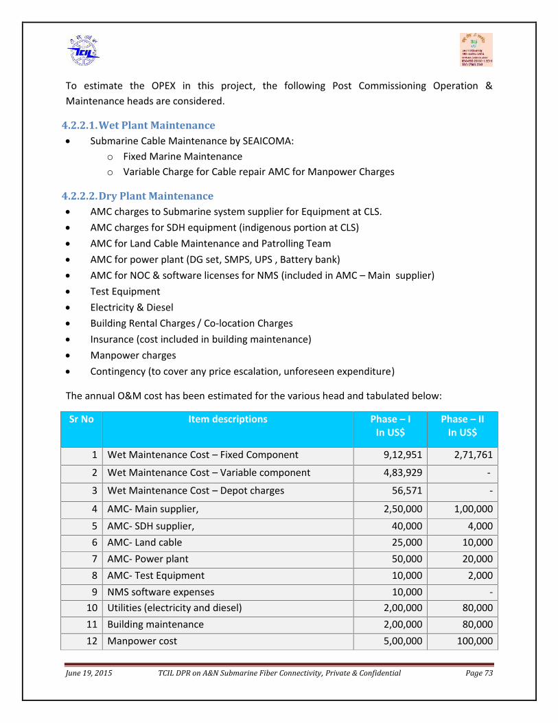
June 19, 2015 TCIL DPR on A&N Submarine Fiber Connectivity, Private & Confidential Page 73
To estimate the OPEX in this project, the following Post Commissioning Operation &Maintenance heads are considered.
4.2.2.1.Wet Plant Maintenance Submarine Cable Maintenance by SEAICOMA:
o Fixed Marine Maintenanceo Variable Charge for Cable repair AMC for Manpower Charges
4.2.2.2.Dry Plant Maintenance AMC charges to Submarine system supplier for Equipment at CLS. AMC charges for SDH equipment (indigenous portion at CLS) AMC for Land Cable Maintenance and Patrolling Team AMC for power plant (DG set, SMPS, UPS , Battery bank) AMC for NOC & software licenses for NMS (included in AMC – Main supplier) Test Equipment Electricity & Diesel Building Rental Charges / Co-location Charges Insurance (cost included in building maintenance) Manpower charges Contingency (to cover any price escalation, unforeseen expenditure)
The annual O&M cost has been estimated for the various head and tabulated below:
Sr No Item descriptions Phase – IIn US$
Phase – IIIn US$
1 Wet Maintenance Cost – Fixed Component 9,12,951 2,71,761
2 Wet Maintenance Cost – Variable component 4,83,929 -
3 Wet Maintenance Cost – Depot charges 56,571 -
4 AMC- Main supplier, 2,50,000 1,00,0005 AMC- SDH supplier, 40,000 4,0006 AMC- Land cable 25,000 10,0007 AMC- Power plant 50,000 20,0008 AMC- Test Equipment 10,000 2,0009 NMS software expenses 10,000 -
10 Utilities (electricity and diesel) 2,00,000 80,00011 Building maintenance 2,00,000 80,00012 Manpower cost 5,00,000 100,000
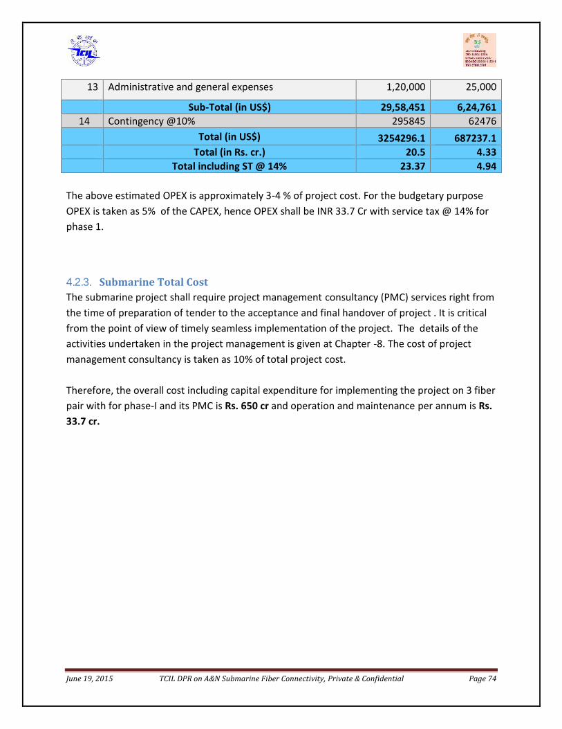
June 19, 2015 TCIL DPR on A&N Submarine Fiber Connectivity, Private & Confidential Page 74
The above estimated OPEX is approximately 3-4 % of project cost. For the budgetary purposeOPEX is taken as 5% of the CAPEX, hence OPEX shall be INR 33.7 Cr with service tax @ 14% forphase 1.
4.2.3. Submarine Total CostThe submarine project shall require project management consultancy (PMC) services right fromthe time of preparation of tender to the acceptance and final handover of project . It is criticalfrom the point of view of timely seamless implementation of the project. The details of theactivities undertaken in the project management is given at Chapter -8. The cost of projectmanagement consultancy is taken as 10% of total project cost.
Therefore, the overall cost including capital expenditure for implementing the project on 3 fiberpair with for phase-I and its PMC is Rs. 650 cr and operation and maintenance per annum is Rs.33.7 cr.
13 Administrative and general expenses 1,20,000 25,000
Sub-Total (in US$) 29,58,451 6,24,76114 Contingency @10% 295845 62476
Total (in US$) 3254296.1 687237.1Total (in Rs. cr.) 20.5 4.33
Total including ST @ 14% 23.37 4.94
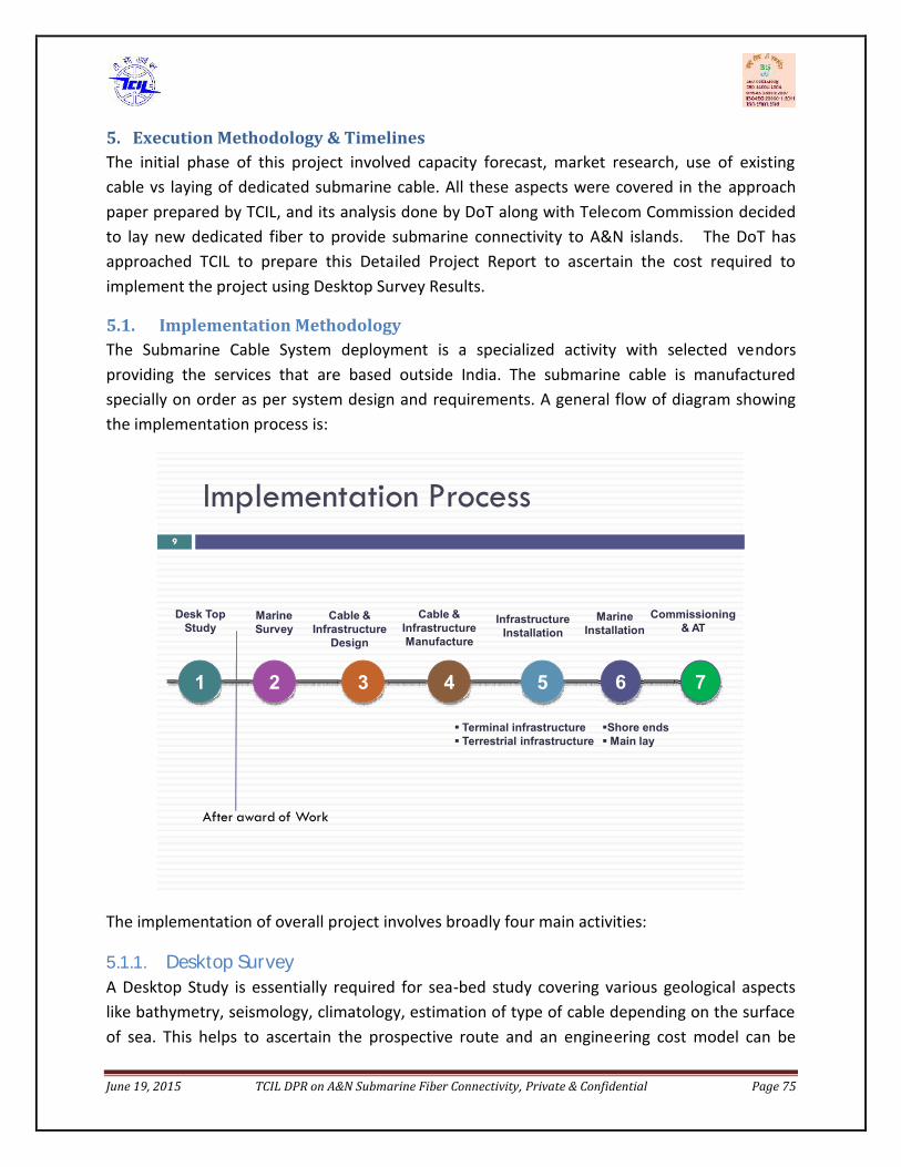
June 19, 2015 TCIL DPR on A&N Submarine Fiber Connectivity, Private & Confidential Page 75
5. Execution Methodology & TimelinesThe initial phase of this project involved capacity forecast, market research, use of existingcable vs laying of dedicated submarine cable. All these aspects were covered in the approachpaper prepared by TCIL, and its analysis done by DoT along with Telecom Commission decidedto lay new dedicated fiber to provide submarine connectivity to A&N islands. The DoT hasapproached TCIL to prepare this Detailed Project Report to ascertain the cost required toimplement the project using Desktop Survey Results.
5.1. Implementation MethodologyThe Submarine Cable System deployment is a specialized activity with selected vendorsproviding the services that are based outside India. The submarine cable is manufacturedspecially on order as per system design and requirements. A general flow of diagram showingthe implementation process is:
Implementation Process9
1 2 3 4 5 6
Desk TopStudy
MarineSurvey
Cable &Infrastructure
Design
Cable &InfrastructureManufacture
InfrastructureInstallation
MarineInstallation
Terminal infrastructure Terrestrial infrastructure
Shore endsMain lay
After award of Work
7
Commissioning& AT
The implementation of overall project involves broadly four main activities:5.1.1. Desktop SurveyA Desktop Study is essentially required for sea-bed study covering various geological aspectslike bathymetry, seismology, climatology, estimation of type of cable depending on the surfaceof sea. This helps to ascertain the prospective route and an engineering cost model can be

June 19, 2015 TCIL DPR on A&N Submarine Fiber Connectivity, Private & Confidential Page 76
arrived at for selection of partners. Further this information is used for budgetary estimation ofthe project. This study is conducted by specialized agency by using the maps/software givingthe information of sea-bed.
TCIL floated a tender to select the vendor for conducting Desktop Study of the submarine routefor this project.
The report submitted by the vendor is enclosed for reference. The entire DTS report issubmitted in two parts:
1. Part – I covering the aspects related to sea-bed study and the data collected during thesite visit. The broad scope of work included Identify the potential Cable landing Station(CLS) and Beach Manholes (BMH) , Submarine Geology , Climatology , Seismology,Oceanography , Commercial Operations, Restricted Areas and Obstructions , BiologicalFactors, Regulatory Factors , Site Visit, Route Recommendation & Marine SurveyRecommendation.
This report can be made available to bidders at the time of tendering to facilitate themin preparing the bid.
2. Part –II covers the network architecture, technical specifications, Bill of Quantity, CAPEX,OPEX, timelines.
This DPR includes the main findings of both these reports viz. BoQ, CAPEX, OPEX, potentialidentified sites for CLS & BMH, timelines etc.
5.1.2. Marine SurveyPost desktop survey project requires marine survey to be carried out, for arriving at the exact
BOQ of equipment to be installed under sea. This activity shall be carried out by the contractorwho shall be implementing this project. On the basis of the results of this survey, the entiresubmarine cable system designing is done.5.1.3. Execution of worksThis will involve the below:
a. Permits & Licenses required to start executionb. Submarine Cable Manufacturing & Laying.c. Terminal station Commissioning.d. Acceptance Testing/Third Party audit
June 19, 2015 TCIL DPR on A&N Submarine Fiber Connectivity, Private & Confidential Page 77
e. Handover/Takeover (HOTO)
The scope of works for each major head is mentioned in subsequent section. The process forimplementing the above activities, involves selection of partner through EOI and tenderprocess.
1. Selection of vendor for desktop survey.2. Selection of vendor for preparation of EIA report which is required to be submitted for thepermissions. .
3. Selection of vendor for marine survey & project execution.
In addition to this, the other activities required to facilitate the implementation of this project iscivil works for readiness of infrastructure required in this project i.e. Beach manholeconstruction, ROW for land cable and laying of duct for same, cable station readiness (AC powerplant, electrical connections, false ceiling, access control etc. other utilities like fire detection &alarm, rodent repellants, CCTV access, water leakage detection etc. Some of the keypermissions required prior to execution of this project like Permit in Principle by DoT, EIA & CRZbeing time consuming should be initiated as a parallel activity.
5.2. Scope of WorkThe marine activities form a critical part of the overall project implementation, ensuring theprovision of a reliable and secure submarine link.
The key elements to ensure success of any Submarine Cable project are:
A thorough Cable Route Study. Accurate data acquisition during the Route Survey. Detailed analysis of survey data leading to optimum route planning and cable engineering. Effective installation and burial of the cable.
The flowchart below gives broad flow of activities involved in a Submarine Cable Project.

June 19, 2015 TCIL DPR on A&N Submarine Fiber Connectivity, Private & Confidential Page 78
Source: http://suboptic.org/Uploads/Files/TuMoB1a.pdfi. Planning and Survey ActivitiesThe key activities involved prior to laying the submarine cable in the marine project are:
Desktop Studies Top level cable routing and engineering Realistic cable quantity estimates Site and route evaluations Hazard risk assessments Solution design Survey management Offshore and post survey route engineering Burial assessment Planning and design Provision of offshore representatives
Desktop StudyA cable route Desktop Study is a key part of the initial phase of any system plan. Properlyexecuted, it should accurately determine core information about the route, such as anoverall risk assessment, submarine project plant quantities and precise detail regardingthe system's security.
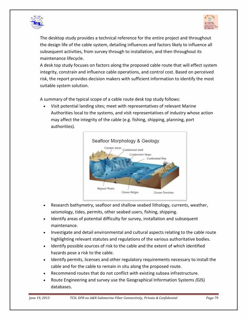
June 19, 2015 TCIL DPR on A&N Submarine Fiber Connectivity, Private & Confidential Page 79
The desktop study provides a technical reference for the entire project and throughoutthe design life of the cable system, detailing influences and factors likely to influence allsubsequent activities, from survey through to installation, and then throughout itsmaintenance lifecycle.A desk top study focuses on factors along the proposed cable route that will effect systemintegrity, constrain and influence cable operations, and control cost. Based on perceivedrisk, the report provides decision makers with sufficient information to identify the mostsuitable system solution.
A summary of the typical scope of a cable route desk top study follows: Visit potential landing sites; meet with representatives of relevant Marine
Authorities local to the systems, and visit representatives of industry whose actionmay affect the integrity of the cable (e.g. fishing, shipping, planning, portauthorities).
Research bathymetry, seafloor and shallow seabed lithology, currents, weather,seismology, tides, permits, other seabed users, fishing, shipping.
Identify areas of potential difficulty for survey, installation and subsequentmaintenance.
Investigate and detail environmental and cultural aspects relating to the cable routehighlighting relevant statutes and regulations of the various authoritative bodies.
Identify possible sources of risk to the cable and the extent of which identifiedhazards pose a risk to the cable.
Identify permits, licenses and other regulatory requirements necessary to install thecable and for the cable to remain in situ along the proposed route.
Recommend routes that do not conflict with existing subsea infrastructure. Route Engineering and survey use the Geographical Information Systems (GIS)
databases.

June 19, 2015 TCIL DPR on A&N Submarine Fiber Connectivity, Private & Confidential Page 80
ii. Marine SurveyBefore finalizing the cable laying route, it is necessary to conduct a detailed survey toinvestigate the seabed and what lies beneath.
Based on the marine survey, the appropriate route for laying the cable (with minimalrocks and with a gradual incline) is identified and the optimum route of the cable isdetermined.
1. Survey for cable laying (Seabed Surface Survey)Multi-beam depth finder is used to survey the topography of the seabed. With themulti-beam depth finder, it is possible to survey a width of a few kilometers at a timeand create a topographical chart of the seabed by processing the data using acomputer. With the latest multi-beam system, the surface soil quality distribution ofthe seabed can also be analyzed from the intensity of the refracted sound wavesfrom the seabed.
2. Survey for cable burying (Seabed Sub-Surface Survey)A survey is conducted to investigate the sub-surface geological layer distribution andthe thickness of the sedimentation layer using side-scan sonar and sub-bottomprofilers for sections that require the cable to be buried. These surveys use lowersound frequencies than those used for the seabed surface survey. In addition, pistoncore samplers are used to collect soil samples at regular intervals to ensure that thesoil is being investigated correctly.
iii. Post Survey Route EngineeringFinally, Post Survey Route Engineering service provides the survey information collectedduring survey and use it to make the final adjustments to the installation route. Theseadjustments require a detailed understanding of the practical installation methodologiesused by installation vessels, combined with the cable industry GIS software skills to utilisethe survey data collected.
Performed either on board the survey vessel in near real time or after the survey iscompleted, the result is the provision of a final route position list (RPL) and Straight LineDiagram (SLD) for installation with precise details of all the necessary cable route events.These typically include; final cable quantities adjusted for correct slack values, cable plantpositions, armor type transitions, cable burial start and end points, crossing points andkey marine boundary positions.

June 19, 2015 TCIL DPR on A&N Submarine Fiber Connectivity, Private & Confidential Page 81
iv. Permits & ClearancesThe permits and clearances required prior to laying any undersea submarine cable system areas follows:
I. Permit in Principle (PIP) – This is required from the parent ministry i.e DoT to initiate theproject.
II. Security Clearance from Ministry of Defense.III. Environmental Clearance – Environment Impact assessment (EIA)IV. NOC from local Authority – ROW/NOC for terrestrial cable laying in islands.V. Operational permits to be obtained by implementation agency from customs, Navy, DG
(shipping) etc.v. Execution of ProjectThe submarine project from installation to commissioning involves a no. of activitiescontractor is supposed to conduct, as listed below:
Engineering, planning, management and coordination of the implementation of the System. Survey and study of the landing beaches, terminal Stations, Marine surveys as defined and
agreed with Purchasers Obtain all necessary permits, except for those permits explicitly defined and agreed with
Purchasers, Undersea Cable Route Clearance as defined and agreed with Purchasers, The loading and testing of the submersible plant and spares on-board the laying ship(s). The delivery, off-loading and testing of the submersible spares in the selected cable
depot(s). Provision of UJ joint kits for the maintenance of the system. Pre-lay grapnel runs as defined and agreed with Purchasers, Design, manufacture, supply and testing of all elements of the System, including spares. Freighting and delivery of all elements of the System, including spares. Provision of all materials, test equipment, labor and services, cable laying vessels, support
crafts, submersible vehicles, cable plows and as defined and agreed with Purchasers, Inspection of the buried Marine cable areas as defined and agreed with Purchasers, Remedial post-lay burial as defined and agreed with Purchasers Installation of shore end cable protection as defined and agreed with Purchasers, Pipe-line and cable crossings as defined and agreed with Purchasers, Provision, Installation and testing of all the elements of the system, including terminal
equipment, land sections, submarine segments, ocean grounds and station grounds asdefined and agreed with Purchasers, with the exception of construction of the beach man

June 19, 2015 TCIL DPR on A&N Submarine Fiber Connectivity, Private & Confidential Page 82
hole(BMH) and the conduits from the BMH to the cable station which will be supplied andinstalled by Purchasers.
HDD and Guard boats when required Detailed Electronic survey of cable route and Cable Route Clearance. Pre-lay Grapnel Run, Laying including Burial as required, Inspection of the buried cable
areas, Remedial post lay cable burial. Permits for Pipelines and Cable Crossings are dealt with in the Terms and Conditions Perform pre and post crossing notifications to cable and pipeline owners. Engineering and installation of all required cable or pipeline crossings to comply with the
latest applicable recommendations by the International Cable Protection Committee (ICPC). The shore end and beach works including the necessary cable protections. (The beach
works shall include the construction/modification of beach manholes, conduits betweenbeach manhole and the ocean/sea, directional drilling works and any other works as may benecessary).
Test equipment whenever required for testing and commissioning. Tool kit per station as required for the implementation and same will be handed over to
Purchasers for O&M purposes. All security measures during all installation phases, including marine installation, land route
and terminal installation Installation and testing of the Data Communication Network (DCN) and Order Wire system
(if applicable) Complete system integration including TSE, MTE, NMS, DCN, and Overall testing and
commissioning of the System Provision of all documentation and Provision of training in the operation and maintenance
of the System( as an option) Supply materials and install cabling to the System demarcation points (Patch panels,
Breaker panels etc.) means Purchasers shall provide AC/DC power upto the respectiveDCPDB and thereafter Contractor shall be responsible for extensions of the same upto theirequipment.
Deployment, transportation, accommodation and other requirements of all its employees/sub-Contractor required for the execution of the Project and for all costs/charges incurredin connection therewith till the date of acceptance.
Deployment of manpower for carrying out the Project, only those manpowerresources who are skilled and experienced in their respective fields and whoare competent to execute or manage/supervise the Project in a proper and timelymanner.

June 19, 2015 TCIL DPR on A&N Submarine Fiber Connectivity, Private & Confidential Page 83
In case of change in its team composition owing to attrition the Contractor shall ensure areasonable amount of time-overlap in activities to ensure proper knowledge transferand handover/takeover of Document and other relevant materials between the outgoingand the new member. The existing team member should be replaced with an equallycompetent substitute from the pool of backup personnel.
Deployment of Electroding generators as defined and agreed with Purchasers and Sub-ductsrequirement, if desired by the purchasers.vi. Project Management
The Project Management is a key activity required in any submarine project to keep it adhere tothe schedule as many unforessen events may arise in a project of this scale. The ProjectManagement Consultant (PMC) would essentially be responsible for:
a. Preparation of Inception Report. This activity has been done by TCIL and report submittedto DoT as Approach Paper.
b. To get the desktop survey of the project in order to come up with authentic requirementson the basis of which tender can be floated. This activity has been done by TCIL. TheDesktop Study reports are accompanied with this DPR.
c. Preparation of Detailed Project Report including Desktop Survey Results. This activity isaddressed in this DPR by TCIL.
d. Preparation of EOI & RFP for selection of vendor. There shall be two to three tendersrequired to be floated for this project 1) EIA assessment 2) Civil Infrastructure readiness 3)Submarine cable laying agency 4) Tender Vetting –technical & legal Expert. This shall includetechnical specifications and legal clauses vetting by expert agency.
e. Tender floating and evaluation. This shall involve tender normalization by expert agency.f. Award of Works to Agency/vendor.g. Supervision of the project against the set timeline.
Design review and lab demonstration of the technology Cable loading & assembly On –board representative during main lay and burial operation.
h. Liasoning for obtaining Permits & Clearances wherever required.i. Acceptance testing/Third Party Audit
Factory audit. Factory Acceptance Tests.
j. Hand over Take over (HOTO)

June 19, 2015 TCIL DPR on A&N Submarine Fiber Connectivity, Private & Confidential Page 84
5.3. Timeline ChartThe indicative timelines for this project is dived into broad categories a) time required to awardthe project and b) time required in execution of this project.5.3.1. Time to Award The ProjectAs per the recent Minutes of Meetings issued after draft DRP presentation on 23/4/15, thetimeline mentioned to take approval from Telecom Commission by August 2015 and thecabinet approval by December 2015. Therefore, the activities required to be undertaken toaward the project shall start in next year. The table showing various targets activity – wise areas below:
S.No Activity Target date Duration Remarks
1. Finalization of DPR May 20152. Approval of DPR (Telecom
Commission & Cabinet)December 2015 7 month
3. Tender preparation for(Submarine Project &EIA Study)
April 2016 4 months Work for permits shouldstart at this point
4. Tender Queries May 2016 1 month5. Bid submission by vendors July 2016 2 months6. Bid Evaluation completed September 2016 2 months7. Placement of Order on vendor October 2016 1 month
TOTAL 17 months CIF (Coming into Force)
5.3.2. Submarine Execution of ProjectThe submarine cable laying projects broadly involves following activities: (PIP) Permit in Principle EIA (Environmental Impact Assessment) & CRZ (Coastal Region Zone) clearance. Marine Survey Submarine Cable Manufacturing Repeater Manufacturing Loading & Transit Custom Clearance Marine Installation Land Cable Manufacturing

June 19, 2015 TCIL DPR on A&N Submarine Fiber Connectivity, Private & Confidential Page 85
RoW for Land Cable Route Land Cable Installation Submarine Equipment Installation at CLS Acceptance Testing & System commissioning (Go Live)
Each activity has a different duration but may get executed in parallel. The time gauged toexecute the project shall be 24 Months from the date of award of project. It is to mention thatthis is subject to award of work date as the suitable months for laying the submarine cable asindicated by DTS vendor are from November to April depending on the monsoon conditions.
A Gantt chart showing the sequence of activities and specific duration is as under:


6. PERMITS & LICENSES
6.1. IntroductionThis section describes the currently available information regarding the Permittingrequirements in the CANI area. Information included in this Section has been sourced from:
Existing data and internet data searches Site Visits made to the proposed landing sites and various authorities in March 2015This Chapter is also covered in Part-T DTS Report.
The regulations and permissions discussed are considered to be correct at the time of writing ofthis section and for the present system.
Governments and Administrative Departments controlling and enforcing the regulationsare beset by changes in the requirements caused by the number of cable applications,changing local and national requirements and the political situation at any time. Newregulations are also being developed all the time to deal with the submarine cableindustry. Discussions with the National Landing parties and regulators should continue toensure trouble-free survey, installation and maintenance operation.
The CANI route will cross waters of India and a stretch of International Waters (High Seas).
The Division for Ocean Affairs and the Law of the Sea (DOALOS), Office of Legal Affairs, UnitedNations Secretariat, presents an online website in order to provide comprehensive informationon:
(i) the deposits with the Secretary-General of the United Nations, pursuant to the UnitedNations Convention on the Law of the Sea, of charts or the lists of geographical coordinates ofpoints, specifying the geodetic datum, in relation to straight baselines and archipelagicbaselines as well as the outer limits of the territorial sea, the exclusive economic zone and thecontinental shelf;
(ii) the discharge of obligations of due publicity to all laws and regulations adopted by thecoastal State relating to innocent passage through the territorial sea and all laws andregulations adopted by States bordering straits relating to transit passage through straits usedfor international navigation, as well as concerning due publicity given by coastal States, inaccordance with the Convention, to the temporary suspension of innocent passage of foreignships in specified areas of the territorial sea;
(iii) the status of State practice.

June 19, 2015 TCIL DPR on A&N Submarine Fiber Connectivity, Private & Confidential Page 88
In addition, the site contains other reference material, such as tables indicating the status ofthe United Nations Convention on the Law of the Sea, summary of national claims to maritimejurisdiction, etc.
(http://www.un.org/Depts/los/LEGISLATIONANDTREATIES/PDFFILES/table_summary_of_claims.pdf)
National legislation, treaties on the delimitation of maritime boundaries and other relevantinformation contained in this Internet publication were obtained from Governments, as well ason occasion from other reliable sources with a view to ensuring the most accuraterepresentation of the current status.
Contact Information for UNCLOS/ DOALOS:Telephone: 212-963-3962Address:Division for Ocean Affairs and the Law of the Sea, Office of Legal AffairsRoom DC2-0450, United Nations, New York, NY 10017, U.S.ADOALOS General email: [email protected]
The maritime territorial claims of India are, as follows:
Territorial Sea * 12 milesContiguous Zone ** 24 milesFisheries or Economic Zone 200 milesContinental Shelf 200 miles or the Continental Margin* The Gulf of Mannar and Palk Bay are claimed as historic waters.** Also considered a Security Zone.
The claimed maritime boundaries (updated as of 2014 data) for the CANI route are illustrated infigure below.

June 19, 2015 TCIL DPR on A&N Submarine Fiber Connectivity, Private & Confidential Page 89
Figure: Maritime claims for the East CANI system routing Area
(Global Maritime Boundaries Database 2013http://www.maritimeboundaries.com/)
Note that the High Seas area is the subject of overlapping Continental Margin claims by Indiaand Sri Lanka; this does not however have any impact on the proposed routing. Details of thedifferent claims have been downloaded from the Continental Shelf Programme website.
(http://www.continentalshelf.org/onestopdatashop/1149.aspx)
6.2. General Permitting RequirementsSeveral different entities have varying responsibilities during the permitting process:
Purchaser - The ultimate owner of the cable system Supplier - The organisation supplying the cable system, which may also actually install the
cable Installer/Contractor - The organisation installing the cable (if not above) and/or Any third party contracted by the installer, for example to carry out the survey
For submarine telecommunication cables installations, several types of permissions are typicallyrequired:
June 19, 2015 TCIL DPR on A&N Submarine Fiber Connectivity, Private & Confidential Page 90
Operator’s License – The license to operate a submarine cable system. Obtained by thePurchaser (or its in-country subsidiaries as appropriate) and issued by the LicensingAuthority (usually a Government Department) of the country in which the installation isproposed.
Permits in Principle or Route/System/Landing Permits and related EIA – The permission, orapproval, to install a cable system within a country’s territorial seas (TS), possibly itsexclusive economic zone (EEZ), and along a terrestrial route to the Terminal Station. Usuallyissued by a Government Department following consultation. For the purpose of this Section,it is assumed that the Installer will work with the Purchaser to acquire all marine permits,whilst the Purchaser nominated Network Provider will be responsible for terrestrial permits.
Operational Permits - Those permits necessary for survey, installation and maintenanceoperations by the Installer/Contractor who is employed on site (whether marine orterrestrial) to carry out day-to-day operations. Marine operational permits will be theresponsibility of the Marine Installer (or its sub contractors) and terrestrial operationalpermits the responsibility of the Purchaser nominated Network Provider. Undertaking theseoperational permits assumes that all relevant Permits in Principle have been obtained.Typical marine operational permit applications may include/require any or all of thefollowing:o Covering letter from applicanto Letter of introduction from Purchaser or its in-country subsidiaryo Letter from the Installer for its survey subcontractor for vessel permittingo Copy of Purchaser/Installer Contracto Letter of appointment of agent by Installero Project schedule/Plan of work (PoW)o Project Scope of Work (SoW)o Route Position Lists (RPLs) and chartlet(s)o Vessel specifications/certificateso Vessels P & I Insurance certificateso Crew lists with certificates and bio-data/visa application/passport detailso Foreign registered vessel exemption application (if applicable)o Copy of vessel charter agreement duly notarised by Public Notary
Permissions from other interested marine users. Although not detailed in this Section, thesewill include crossing permissions from other cable owners or concessions operators. Suchpermissions may either be a simple written “Agreement to Cross” or a more complex legal“Crossing Agreement”. This choice will be entirely dependent on the requirements of thecompany whose interests are to be crossed and the negotiations between Purchaser andthat relevant company. This also includes agreements to cross Oil and Gas ConcessionAreas, Military Areas and Agreement with Fisheries Unions (as appropriate).
Survey works can usually commence prior to the Customer obtaining an Operator’s Licence.Application for installation operational permits and therefore commencement of installation

June 19, 2015 TCIL DPR on A&N Submarine Fiber Connectivity, Private & Confidential Page 91
however will not be able to be undertaken until both the Operator’s Licence and relevantPermits in Principle are in place.
The various permits, licences and permissions indicated in this section commonly need to beapplied for in a set order as each new application often requires that those preceding it havealready been approved.
The Permitting requirements are often on the critical path for cable commissioning, and timecan frequently be saved if the Purchaser/Supplier/Contractor commences the applicationprocess at the earliest possible time.
Note that the definitive list of Survey and Installation Permitting requirements will onlygenerally be available upon completion of initial discussions with the relevant permittingauthorities as part of the permitting process itself.
It is also now common for Environmental Impact Assessments (EIAs) to be requested whichmay require surveys, studies and assessments, usually limited to Territorial Seas or coastalwaters. Such requirements will be stipulated during the “Permits in Principle” process. If issueof any permit is subject to an EIA process, or any other environmental consent, conditions maybe attached which require installation vessels to comply with certain environmental criteria. Assuch, it is advised that all requirements are established prior to operations, and that all worksare carried out in compliance with these requirements.
Note that a Permit Matrix is a live document that will undergo continual refinement andupdating during the course of a project. It is not possible to fully identify all Permittingrequirements in advance as the procedures change from case to case.
6.3. India PermittingThe general Permitting Requirements for survey and installation in India are set out below:6.3.1. Permit in Principle (PIP)
Local BodyCorporation/administration (for land acquisition, digging of roads, laying of cables and forinformation on future/planned development in that area)
State GovernmentState Government departments related to Highways, Public Works (PWD), Fisheries, ElectricityBoard, Pollution, Maritime Board, Port & Mercantile etc for information and permission

June 19, 2015 TCIL DPR on A&N Submarine Fiber Connectivity, Private & Confidential Page 92
Central Government Ministry of Telecommunications (Nodal Agency) Ministry of Defense (Agency for survey in Indian EEZ, Territorial waters & Andaman sea
besides construction and other related offshore activities) Ministry of Home Affairs / Ministry of External Affairs (Agency for issue of permit for
foreign national to work in India and operate from vessels in Indian waters) Ministry of Environment (Agency for environmental clearance), etc for permission of cable
laying, operating vessel for survey, installation and maintenance, etc.
The applications for all permission in respect of all the activities involving the above have to bemade by the owners (CANI) as the governmental bodies do not entertain requests fromcontractors, because the government recognizes only the owners for all details of the project. Itis estimated that the turnaround period for processing and according permission would takeapproximately four months from the date of submission of the relevant papers by theowners/applicants to the governmental agencies.
After approval in principle is obtained by the applicants, the other permissions will generally beavailable in up to 8 weeks.
6.3.2. Operational PermitsIt is believed that a CLS will need to be in place in order to get an Operational Permit for cablelaying but this will be confirmed in the ongoing permit matrix as the project proceeds. It isunderstood that the CLS is not essential to obtain a Permit for survey.
Survey and Installation Operation Activities:Operational Permits need to be applied for in parallel with the MOFA Permit if they are not todelay the progress of the project.Once the in-principle approval from MOFA has been received, documents can be submitted toMOFA for both survey and installation activities. Documentation must include:
A project description Survey areas chartlets Route Position Lists (RPLs) Survey crew lists (including passport details) Vessel crew lists (including passport details) Vessel details Vessel certificates Lists of proposed equipment Project schedule

June 19, 2015 TCIL DPR on A&N Submarine Fiber Connectivity, Private & Confidential Page 93
No definitive details on permit application times were secured during the site visits, howeverthe inference from most Government Departments liaised with was that approximately 3 to 4months would be required to review any application made.
The cable laying operation can be split into two categories: one relating to activities offshoreand the second related to activities onshore.
For Offshore Activities:The Govt. of India and Maritime Board are the principal agencies from whom requisitepermission has to be taken.The Maritime Board requires details of the project as well as the application to come from theend user and they shall not entertain any intermediaries. The board officials meet once every 3months and shall study the project/proposal after which they shall reply. The board may levycharges depending on the nature of project and end user. The jurisdiction of the board is fromthe territorial waters of India (12 Nautical Miles from base line) up to the High Water Line.
For Onshore Activities:As per the Government of India regulations the area falling from High Water Line to about 200metres come under the Coastal Zone Regulation act and all permits have to be obtained fromthe Ministry of Environment and Forests.The State Government Information Technology Department is the main regulatory authority foractivities on the onshore portion. The location of the proposed beach man hole and theonshore cable route from the beach man hole to the terminal point lie in this region.
All permissions for all activities for Optic Fibre Cable activities here are to be addressed to theInformation Technology Department, which shall act as a single nodal body by coordinating andgetting necessary approvals from statutory bodies. The Information Technology Departmentrequire full technical specifications of the cables, laying procedure, burial operations etc. alongwith the details of the route proposed to be followed till the terminal point includingcontingency plan for re-routing in case of emergency operations.
6.4. Andaman and Nicobar IslandsThe Andaman and Nicobar Islands are a security sensitive area and Entry Formalities apply.Some areas are closed to visitors and some Nationalities are barred from obtaining visit visas.
1. Andaman and Nicobar Islands being a restricted area under the Foreigners (RestrictedAreas) Order, 1963, no foreigners can enter or stay in the Islands without obtaining permitfrom the competent authority. At present foreigners can visit the following places for thirtydays after obtaining Restricted Areas Permit from the competent authority.

June 19, 2015 TCIL DPR on A&N Submarine Fiber Connectivity, Private & Confidential Page 94
Day and Night Visit Allowed Municipal Area, Port Blair Havelock Island Long Island Neil Island Diglipur Mayabunder Rangat
Only Day visit allowed Jolly Bouy Red skin South Cinque Mount Harriet Madhuban
2. The question of opening of more places in Andaman and Nicobar islands for promotion oftourism has been under active consideration of the Government of India for quite sometime. It has now been decided to open the following additional places for foreign touristsin Andaman and Nicobar Islands:
Places opened for day and night visits Entire Island of Middle Andaman, excluding tribal reserve. All Islands in Mahatma Gandhi Marine National Park except Boat, Hobday, Twin Islands,
Tarmugli, Malay and Pluto (Night halt in these Islands subject to special permission of theUT Administration.
Entire Island of South Andaman, excluding tribal reserve. Baratang Islands. North Passage Island. Little Andamans Island excluding Tribal reserve.
Places opened for day visit only Ross Island. Narcondum Island. Interview Island. Brother Island. Sister Island. Barren Island: Restricted to visit on board vessels only with no landing ashore.
June 19, 2015 TCIL DPR on A&N Submarine Fiber Connectivity, Private & Confidential Page 95
3. The foreign tourists will be allowed to visit the open areas in the Andaman & NicobarIslands subject to the guidelines issued vide Ministry of Home Affairs circularNo.15011/14/91-F.I dated 30.06.92 which are produced:-
The visiting parties would invariably be accompanied by a guide nominated by the ChiefWildlife Warden of Andaman & Nicobar Islands and should follow the code of conduct inthe park areas.
Visitors should pay an entry fee. In case of violation of National Marine Park code, suitablefine may be imposed on the offender by the A&N Islands Administration.
No jetties or permanent structures are to be allowed to be built upon or off the islands. Nobar-be-que or other cooking is allowed. Only thatched enclosures to serve as toilets madeof local materials are to be permitted. No brick and mortar shelters for shade should beallowed to be made. Lean to shelters for shade may be allowed to be made.
Forest should not be diverted for any purpose. Permanent structures like hotelaccommodation etc. should not be allowed to come up. I.D.A guidelines should be strictlyadhered to and the Coastal Zone Regulations should also be followed in letter and spirit.
Visit to the Marine Park areas is to be restricted to small boats or glass bottom boats. No oilleakage is to be allowed in the area.
Scuba Diving and underwater photography is to be permitted in identified areas, but noremoval of coral, fish or any other item from Marine Park is to be permitted.
Restricted Area Permit issued in this regard by agencies would incorporate the word"Subject to restrictions imposed by the Chief Wild Life Warden, Andaman & NicobarIslands."
Foreigners visit to the Islands of Mount Harriet and Madhuban would be regulated by theAndaman & Nicobar Islands Administration in consultation with the wildlife representativesin A&N Islands.
Guidelines issued by the Ministry of Environment and Forest from time to time will beadhered to by the A&N Islands Administration while regulating tourist traffic to the Islands.
As regards the two volcanic Islands, Barren Island and Narcondum Island foreign touristsmay be allowed to visit Barren Island on board vessels but no landing ashore. UTAdministration would provide escort to the tourists visiting the Islands. For NarcondumIslands it has been decided that it may be opened to foreign tourists for diving andunescorted day visits.
No Burmese national will be allowed to visit Mayabunder and Diglipur without priorpermission of the Ministry of Home Affairs.
4. It has been further decided that the authorities competent to issue Restricted Area Permitcould continue to be same as are at present, namely:-
All Indian Missions and posts abroad. F.R.R.Os, Delhi, Kolkata and Mumbai. Chief Immigration Officer, Chennai. Immigration Officer, Port Blair.

June 19, 2015 TCIL DPR on A&N Submarine Fiber Connectivity, Private & Confidential Page 96
Duration of Stay5. It has further been decided that the individual foreign tourists may be permitted to visit
the above places in accordance with the conditions imposed. The total period of stay inAndaman & Nicobar Island shall be for a maximum period of 30 days. The period of staycan be extended for another 15 days as per power delegated to the Administration by theGovt. of India. The Superintendent of Police, South Andaman District is the competentauthority in this regard.
The following should be noted: Visit of Foreigners: Any foreigner coming to Port Blair, should come with a valid visa. On
arrival at Port Blair, foreigners will be issued a Restricted Area Permit, which will be validfor 30 days which allows foreigners to visit areas open for foreigners.
For visiting Nicobars: There is a special permit called a Tribal Pass, which is issued by theDeputy Commissioner. This Pass is required by both Indian and Foreign Nationals. Gettingthis Pass is time consuming and therefore we need to apply for this Pass well in time. ForTribal Pass requirements are as follows:
o Passport size photographs (2)o Attested photocopy of addresso Covering letter duly mentioning the reason for visit.
The Application Form for visits to the Andaman and Nicobar Islands is given in Appendix D.
6.5. Permitting Procedure & Lead-time SummaryThe summary provided below should be regarded as indicative only; actual Permitting timeswill depend on the status of the applicant and the urgency with which Permitting is pursued.However it should be stressed that Permitting is a time consuming process and if insufficienttime is allowed for this the project will be delayed and both survey and installation activitiesrisk being forced into periods of the year when the weather is unfavourable, with a resultantincrease in costs and potential adverse effect on the final cable installation.
Permit Title orDescription
Permit GrantingAuthority andPOC Details
Application Requirements (SupportingDocumentation)
EstimatedDuration forApplication
ApprovalPermit inPrinciple (PIP)permission forthe cable layingproject
Ministry ofCommunicationDoT Govt. of India
Submission of the application byPurchaser
2 Months
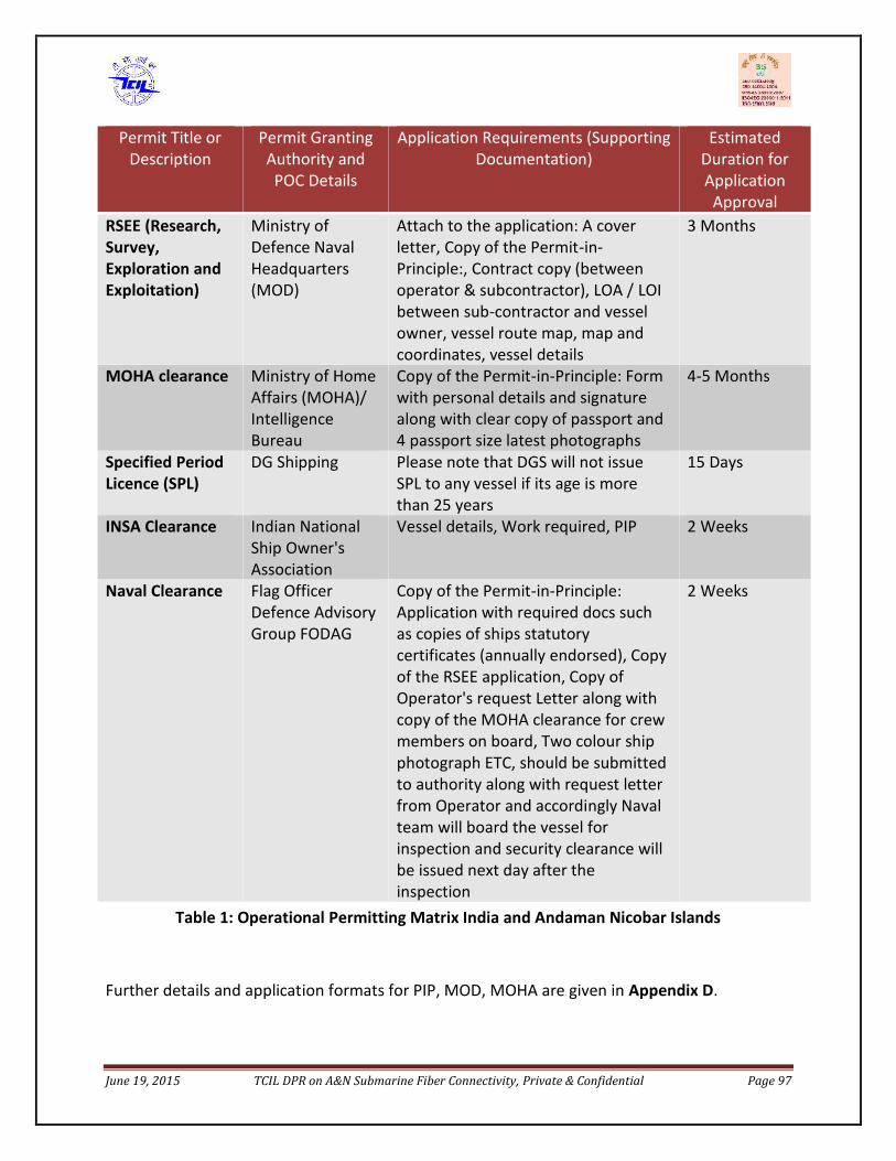
June 19, 2015 TCIL DPR on A&N Submarine Fiber Connectivity, Private & Confidential Page 97
Permit Title orDescription
Permit GrantingAuthority andPOC Details
Application Requirements (SupportingDocumentation)
EstimatedDuration forApplication
ApprovalRSEE (Research,Survey,Exploration andExploitation)
Ministry ofDefence NavalHeadquarters(MOD)
Attach to the application: A coverletter, Copy of the Permit-in-Principle:, Contract copy (betweenoperator & subcontractor), LOA / LOIbetween sub-contractor and vesselowner, vessel route map, map andcoordinates, vessel details
3 Months
MOHA clearance Ministry of HomeAffairs (MOHA)/IntelligenceBureau
Copy of the Permit-in-Principle: Formwith personal details and signaturealong with clear copy of passport and4 passport size latest photographs
4-5 Months
Specified PeriodLicence (SPL)
DG Shipping Please note that DGS will not issueSPL to any vessel if its age is morethan 25 years
15 Days
INSA Clearance Indian NationalShip Owner'sAssociation
Vessel details, Work required, PIP 2 Weeks
Naval Clearance Flag OfficerDefence AdvisoryGroup FODAG
Copy of the Permit-in-Principle:Application with required docs suchas copies of ships statutorycertificates (annually endorsed), Copyof the RSEE application, Copy ofOperator's request Letter along withcopy of the MOHA clearance for crewmembers on board, Two colour shipphotograph ETC, should be submittedto authority along with request letterfrom Operator and accordingly Navalteam will board the vessel forinspection and security clearance willbe issued next day after theinspection
2 Weeks
Table 1: Operational Permitting Matrix India and Andaman Nicobar Islands
Further details and application formats for PIP, MOD, MOHA are given in Appendix D.
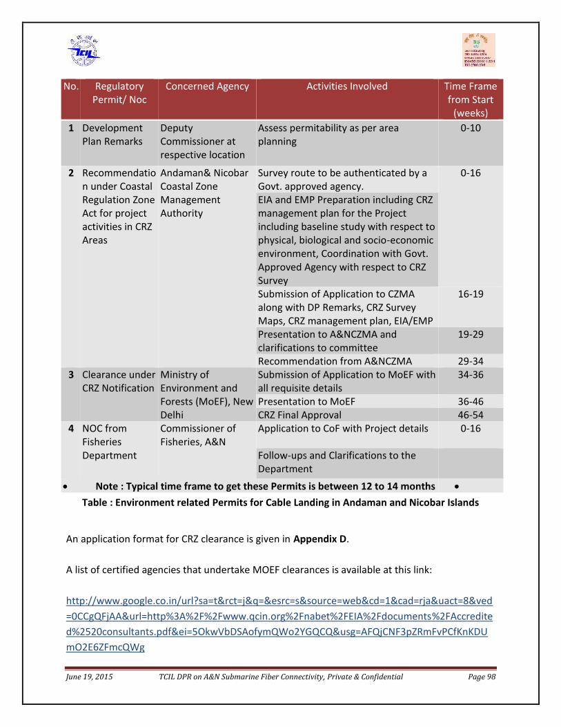
June 19, 2015 TCIL DPR on A&N Submarine Fiber Connectivity, Private & Confidential Page 98
No. RegulatoryPermit/ Noc
Concerned Agency Activities Involved Time Framefrom Start
(weeks)1 Development
Plan RemarksDeputyCommissioner atrespective location
Assess permitability as per areaplanning
0-10
2 Recommendation under CoastalRegulation ZoneAct for projectactivities in CRZAreas
Andaman& NicobarCoastal ZoneManagementAuthority
Survey route to be authenticated by aGovt. approved agency.
0-16
EIA and EMP Preparation including CRZmanagement plan for the Projectincluding baseline study with respect tophysical, biological and socio-economicenvironment, Coordination with Govt.Approved Agency with respect to CRZSurveySubmission of Application to CZMAalong with DP Remarks, CRZ SurveyMaps, CRZ management plan, EIA/EMP
16-19
Presentation to A&NCZMA andclarifications to committee
19-29
Recommendation from A&NCZMA 29-343 Clearance under
CRZ NotificationMinistry ofEnvironment andForests (MoEF), NewDelhi
Submission of Application to MoEF withall requisite details
34-36
Presentation to MoEF 36-46CRZ Final Approval 46-54
4 NOC fromFisheriesDepartment
Commissioner ofFisheries, A&N
Application to CoF with Project details 0-16
Follow-ups and Clarifications to theDepartment
Note : Typical time frame to get these Permits is between 12 to 14 months Table : Environment related Permits for Cable Landing in Andaman and Nicobar Islands
An application format for CRZ clearance is given in Appendix D.
A list of certified agencies that undertake MOEF clearances is available at this link:
http://www.google.co.in/url?sa=t&rct=j&q=&esrc=s&source=web&cd=1&cad=rja&uact=8&ved=0CCgQFjAA&url=http%3A%2F%2Fwww.qcin.org%2Fnabet%2FEIA%2Fdocuments%2FAccredited%2520consultants.pdf&ei=5OkwVbDSAofymQWo2YGQCQ&usg=AFQjCNF3pZRmFvPCfKnKDUmO2E6ZFmcQWg
June 19, 2015 TCIL DPR on A&N Submarine Fiber Connectivity, Private & Confidential Page 99
7. RISKS & HAZARDS
The detailed desktop study done by M/s OSS using special database of sea-bed data and sitevisits conducted at the A&N islands. The report by M/s OSS (Part –I DTS Report) covers in detailthe various aspects of the submarine route under consideration like geology, climatology,seismology oceanography, biological factors. This report may be made available to bidders atthe time of tender with the help of which the bidders shall be able to submit the bid.
The various main risks that may be encountered while execution of this project are bulletedbelow:
Adverse sea conditions, particularly from June to August Cyclones, with peak activity from April to December, with most activity in
October/November Trawling activity to around 400m WD on the continental shelf off Chennai and to around
750m WD along the Andaman-Nicobar Island arc. Anchorages and Port activity near the routes at Chennai, Little Andaman Island and Kamorta Hydrocarbon concessions with likely exploration activity Submarine cables, including several IS cables converging on Chennai and both IS and
Planned cables in the Bay of Bengal A Military exercise area which is unavoidable at Chennai and a further area that has been
avoided east of Greater Andaman Island Several wrecks on the continental shelves A moderate Piracy risk, particularly in port at Chennai Rock and coral outcrops on the continental shelf are expected to prevent effective cable
burial in many areas in the Andaman and Nicobar Islands, exposing the cable to risk fromexternal aggression
Marine Volcanism and Hydrothermal Vents in the Andaman Sea may result in lava or hotwater engulfing the cable
Tsunami represent a significant risk to the BMH locations at all landfalls except Kamorta
The risks and hazards have been broadly classified and tabulated below for ready reference.
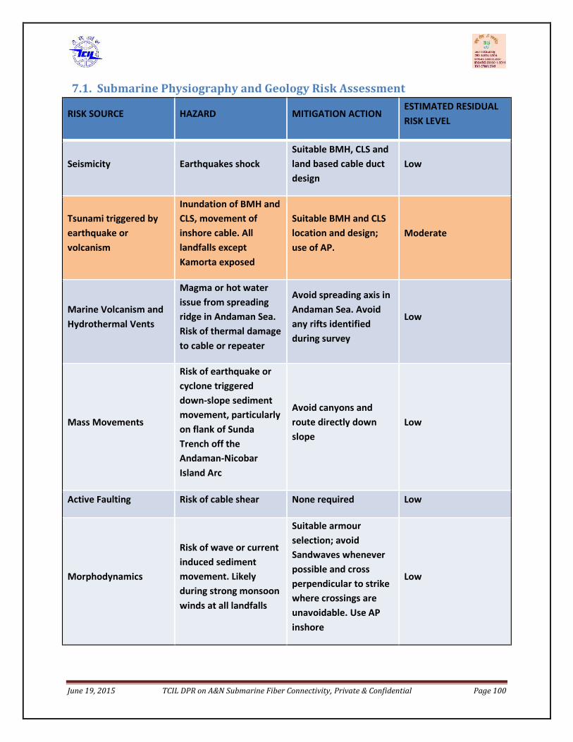
June 19, 2015 TCIL DPR on A&N Submarine Fiber Connectivity, Private & Confidential Page 100
7.1. Submarine Physiography and Geology Risk Assessment
RISK SOURCE HAZARD MITIGATION ACTIONESTIMATED RESIDUALRISK LEVEL
Seismicity Earthquakes shockSuitable BMH, CLS andland based cable ductdesign
Low
Tsunami triggered byearthquake orvolcanism
Inundation of BMH andCLS, movement ofinshore cable. Alllandfalls exceptKamorta exposed
Suitable BMH and CLSlocation and design;use of AP.
Moderate
Marine Volcanism andHydrothermal Vents
Magma or hot waterissue from spreadingridge in Andaman Sea.Risk of thermal damageto cable or repeater
Avoid spreading axis inAndaman Sea. Avoidany rifts identifiedduring survey
Low
Mass Movements
Risk of earthquake orcyclone triggereddown-slope sedimentmovement, particularlyon flank of SundaTrench off theAndaman-NicobarIsland Arc
Avoid canyons androute directly downslope
Low
Active Faulting Risk of cable shear None required Low
Morphodynamics
Risk of wave or currentinduced sedimentmovement. Likelyduring strong monsoonwinds at all landfalls
Suitable armourselection; avoidSandwaves wheneverpossible and crossperpendicular to strikewhere crossings areunavoidable. Use APinshore
Low
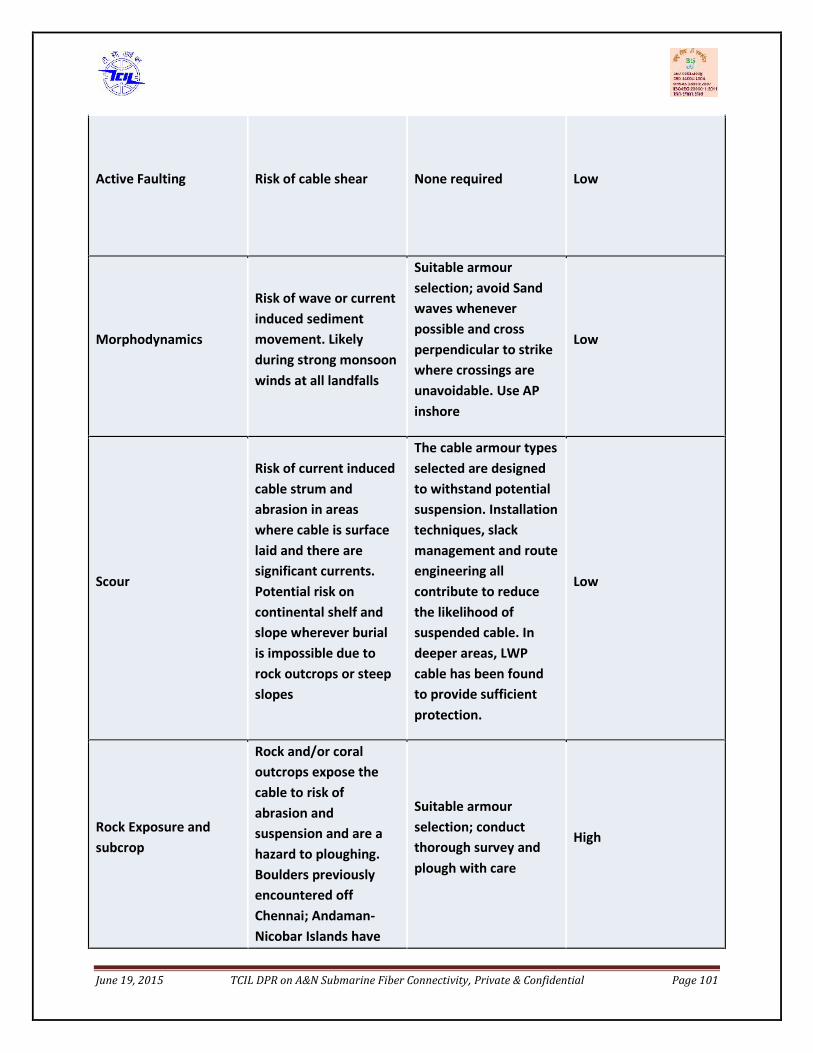
June 19, 2015 TCIL DPR on A&N Submarine Fiber Connectivity, Private & Confidential Page 101
Active Faulting Risk of cable shear None required Low
Morphodynamics
Risk of wave or currentinduced sedimentmovement. Likelyduring strong monsoonwinds at all landfalls
Suitable armourselection; avoid Sandwaves wheneverpossible and crossperpendicular to strikewhere crossings areunavoidable. Use APinshore
Low
Scour
Risk of current inducedcable strum andabrasion in areaswhere cable is surfacelaid and there aresignificant currents.Potential risk oncontinental shelf andslope wherever burialis impossible due torock outcrops or steepslopes
The cable armour typesselected are designedto withstand potentialsuspension. Installationtechniques, slackmanagement and routeengineering allcontribute to reducethe likelihood ofsuspended cable. Indeeper areas, LWPcable has been foundto provide sufficientprotection.
Low
Rock Exposure andsubcrop
Rock and/or coraloutcrops expose thecable to risk ofabrasion andsuspension and are ahazard to ploughing.Boulders previouslyencountered offChennai; Andaman-Nicobar Islands have
Suitable armourselection; conductthorough survey andplough with care
High
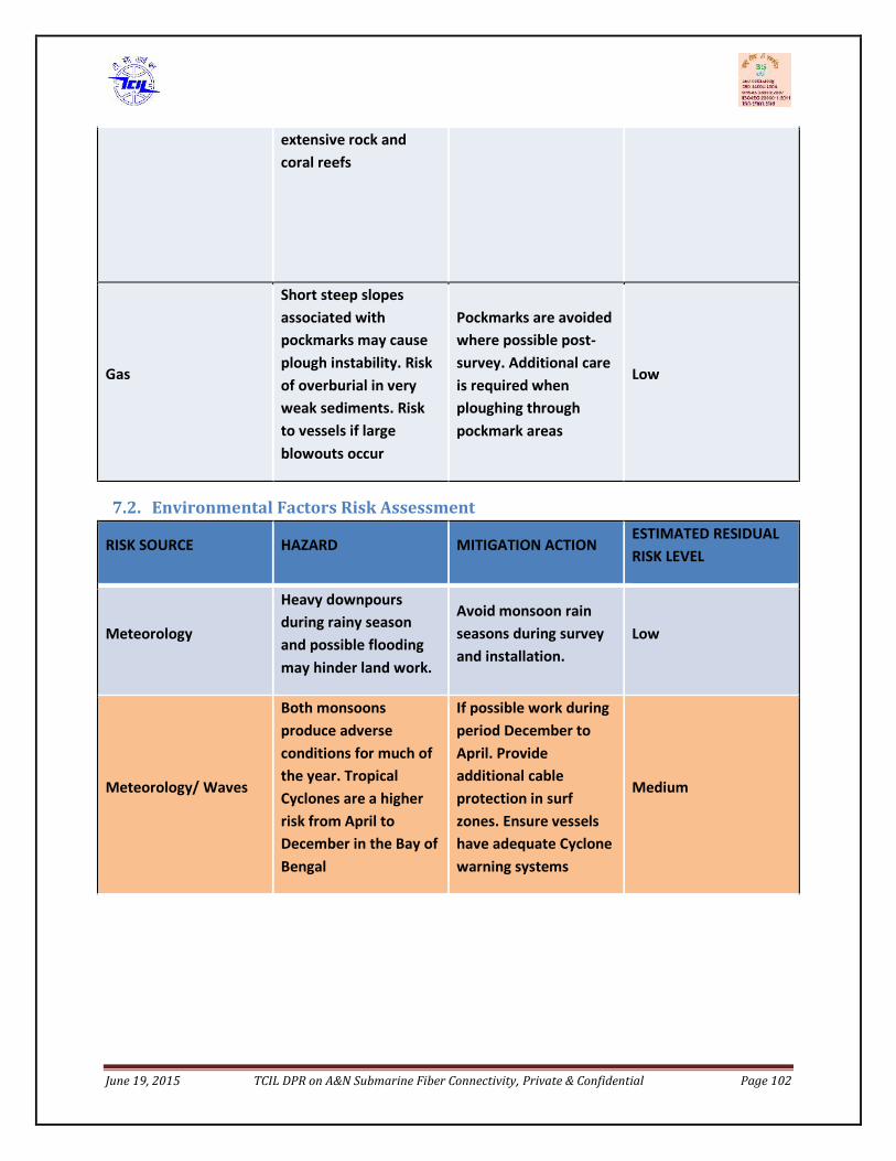
June 19, 2015 TCIL DPR on A&N Submarine Fiber Connectivity, Private & Confidential Page 102
extensive rock andcoral reefs
Gas
Short steep slopesassociated withpockmarks may causeplough instability. Riskof overburial in veryweak sediments. Riskto vessels if largeblowouts occur
Pockmarks are avoidedwhere possible post-survey. Additional careis required whenploughing throughpockmark areas
Low
7.2. Environmental Factors Risk Assessment
RISK SOURCE HAZARD MITIGATION ACTIONESTIMATED RESIDUALRISK LEVEL
Meteorology
Heavy downpoursduring rainy seasonand possible floodingmay hinder land work.
Avoid monsoon rainseasons during surveyand installation.
Low
Meteorology/ Waves
Both monsoonsproduce adverseconditions for much ofthe year. TropicalCyclones are a higherrisk from April toDecember in the Bay ofBengal
If possible work duringperiod December toApril. Provideadditional cableprotection in surfzones. Ensure vesselshave adequate Cyclonewarning systems
Medium
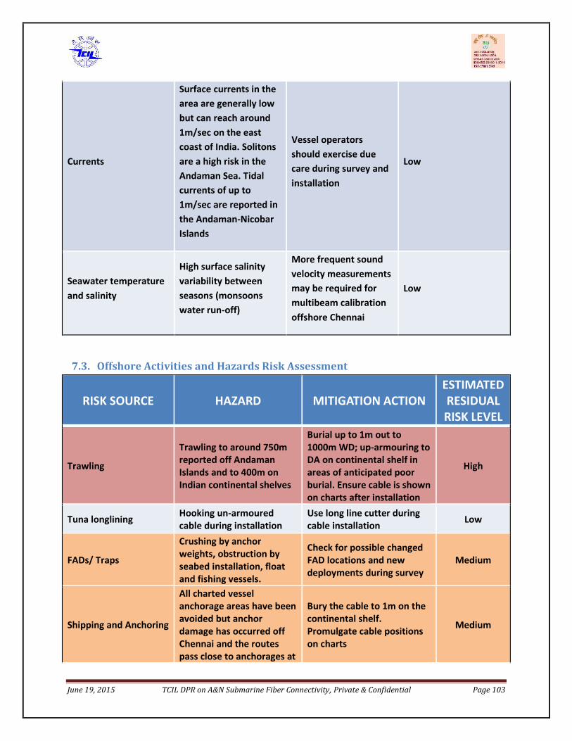
June 19, 2015 TCIL DPR on A&N Submarine Fiber Connectivity, Private & Confidential Page 103
Currents
Surface currents in thearea are generally lowbut can reach around1m/sec on the eastcoast of India. Solitonsare a high risk in theAndaman Sea. Tidalcurrents of up to1m/sec are reported inthe Andaman-NicobarIslands
Vessel operatorsshould exercise duecare during survey andinstallation
Low
Seawater temperatureand salinity
High surface salinityvariability betweenseasons (monsoonswater run-off)
More frequent soundvelocity measurementsmay be required formultibeam calibrationoffshore Chennai
Low
7.3. Offshore Activities and Hazards Risk Assessment
RISK SOURCE HAZARD MITIGATION ACTIONESTIMATEDRESIDUALRISK LEVEL
Trawling
Trawling to around 750mreported off AndamanIslands and to 400m onIndian continental shelves
Burial up to 1m out to1000m WD; up-armouring toDA on continental shelf inareas of anticipated poorburial. Ensure cable is shownon charts after installation
High
Tuna longlining Hooking un-armouredcable during installation
Use long line cutter duringcable installation Low
FADs/ Traps
Crushing by anchorweights, obstruction byseabed installation, floatand fishing vessels.
Check for possible changedFAD locations and newdeployments during survey
Medium
Shipping and Anchoring
All charted vesselanchorage areas have beenavoided but anchordamage has occurred offChennai and the routespass close to anchorages at
Bury the cable to 1m on thecontinental shelf.Promulgate cable positionson charts
Medium
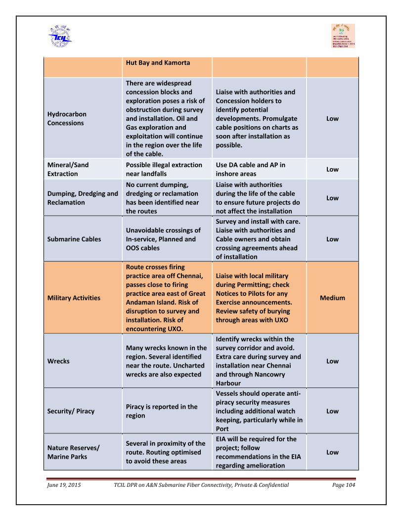
June 19, 2015 TCIL DPR on A&N Submarine Fiber Connectivity, Private & Confidential Page 104
Hut Bay and Kamorta
HydrocarbonConcessions
There are widespreadconcession blocks andexploration poses a risk ofobstruction during surveyand installation. Oil andGas exploration andexploitation will continuein the region over the lifeof the cable.
Liaise with authorities andConcession holders toidentify potentialdevelopments. Promulgatecable positions on charts assoon after installation aspossible.
Low
Mineral/SandExtraction
Possible illegal extractionnear landfalls
Use DA cable and AP ininshore areas Low
Dumping, Dredging andReclamation
No current dumping,dredging or reclamationhas been identified nearthe routes
Liaise with authoritiesduring the life of the cableto ensure future projects donot affect the installation
Low
Submarine CablesUnavoidable crossings ofIn-service, Planned andOOS cables
Survey and install with care.Liaise with authorities andCable owners and obtaincrossing agreements aheadof installation
Low
Military Activities
Route crosses firingpractice area off Chennai,passes close to firingpractice area east of GreatAndaman Island. Risk ofdisruption to survey andinstallation. Risk ofencountering UXO.
Liaise with local militaryduring Permitting; checkNotices to Pilots for anyExercise announcements.Review safety of buryingthrough areas with UXO
Medium
Wrecks
Many wrecks known in theregion. Several identifiednear the route. Unchartedwrecks are also expected
Identify wrecks within thesurvey corridor and avoid.Extra care during survey andinstallation near Chennaiand through NancowryHarbour
Low
Security/ Piracy Piracy is reported in theregion
Vessels should operate anti-piracy security measuresincluding additional watchkeeping, particularly while inPort
Low
Nature Reserves/Marine Parks
Several in proximity of theroute. Routing optimisedto avoid these areas
EIA will be required for theproject; followrecommendations in the EIAregarding amelioration
Low
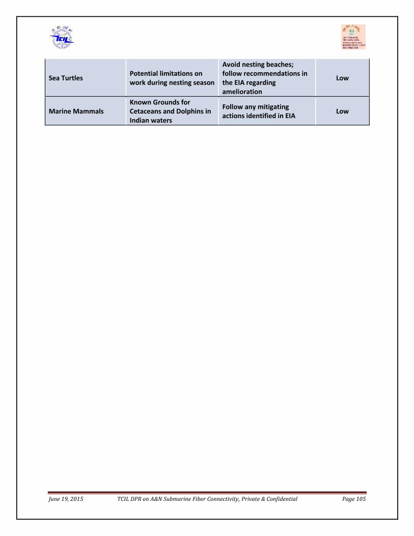
June 19, 2015 TCIL DPR on A&N Submarine Fiber Connectivity, Private & Confidential Page 105
Sea Turtles Potential limitations onwork during nesting season
Avoid nesting beaches;follow recommendations inthe EIA regardingamelioration
Low
Marine MammalsKnown Grounds forCetaceans and Dolphins inIndian waters
Follow any mitigatingactions identified in EIA Low
June 19, 2015 TCIL DPR on A&N Submarine Fiber Connectivity, Private & Confidential Page 106
8. Project Management Consultant
8.1. Project management aspects
The Project Management Consultancy services are critical in the project of this scale where thesystem is designed and implemented by a expert agency, permits are required from Indiangovernment, liasoning with local authorities is required for successful commissioning of thisproject.The project management activities for the cable owner for this project would be broadly four-faceted as following;
i. Tendering (tender formation, evaluation, equalization, providing contractorclarifications, and contract formation)
ii. Permitsiii. Supply contract managementiv. Cable station and infrastructure readinessv. Roll out and O&M readiness
Tendering(tender formation, evaluation and contract formation)
The Tendering tasks would comprise of preparing tender documents, receiving responses,analyzing, equalizing and evaluating the offers as per developed evaluation criteria. After thetechnical evaluation and offer equalization, the winning tenderer is decided. The systemdescription submitted by the (winning) tenderer is then scrutinized in detail, the unaddressedissues and requirements are discussed and finalized and the contract document is developedfor signature.
After fulfillment of certain commercial conditions by the supplier, the contract comes intoforce.
The tender documents for submarine systems, as per standard international practice, compriseof various document packages, important of which are;
Commercial terms and conditions, Technical package containing specifications, network requirement, design and performance
parameters, installation and marine activity procedures, support and warranty procedures,acceptance procedures etc.
Price schedules
The entire process from tender formation till contract signature might take 4-6 months.

June 19, 2015 TCIL DPR on A&N Submarine Fiber Connectivity, Private & Confidential Page 107
Permits
The activities would require to be commenced much before supply contract comes into force.These would typically involve, understanding the permit requirements completely, putting aplan in place to acquire the required permits duly considering risks and contingency, initiatingaction according to the plan and constant follow-up with the concerned third party (if engaged)or the government authority. Timey escalation and engagement with correct follow-up atsenior level forms the key for timely acquisition of permits.
A crucial impact of any delays incurred in securing permits that are the responsibility of theowners, may be used as an opportunity by the suppliers as a reason for cost increase and delaysin project implementation. Hence it important that firstly, the scope and timelines of permitsare agreed with the supplier during contract formation with great care and once agreed allefforts should be made to obtain the subject permits well in time.
As mentioned in Part 1, there are two main permits under cable owner responsibility;
PIP (Permit-in-Principle) CRZ clearance
Among the two, CRZ is of utmost importance, as it is historically known to have taken severalmonths to be available and for this particular project since the Andaman Islands areenvironmentally sensitive zones, hence the time taken could be even more. An EIA would alsoneed to be performed during the course of seeking the permits
As already suggested, CRZ clearance must be initiated in parallel with tendering stage. The PIPneed to be available within a couple of weeks of supply contract coming into force,so that thechosen supplier could then use it to timely initiate other operational permits without having animpact on their plan of work, (marine survey being the first ones).
Besides PIP and CRZ, the cable owners would be routinely required to sign the documents ofvarious operational permits too during the project execution cycle, as the permits can be issuedby the agencies only in the name of the cable owner. The supplier would perform the tasks ofprocessing applications, submitting and follow-up with the require agencies but allcorrespondence would be routed through the cable owner. Hence prior understanding ofprocess and requirements would help achieve better coordination with the supplier.
Supply contract management
These activities would commence with contract CIF and would require constant engagementwith the chosen supplier, monitoring the progress along an agreed plan of work, deviationsfrom schedule and day-to-day management of issues that come up. The important thing here
June 19, 2015 TCIL DPR on A&N Submarine Fiber Connectivity, Private & Confidential Page 108
would be to contain cost escalations, and make sure that the project is executed in the agreedtime frame.
In addition, many technical visits would also need to be undertaken immediately after supplycontract comes into force and may continue from time to time till the project commissioning.These may include;
System design review and acceptance Lab demonstration Factory audit &acceptance tests Cable acceptance and loading Various stages of on-site testing for approving completion and acceptance of milestones as
per specs Ship representatives during survey &cable lay operations
Besides the technical visits, the technical team would be required to develop various test plans,tests schedules, review detailed engineering specifications of manufacturing and performremote verification of many manufacturing tests. Their acceptance would lead to payment ofcertain billing milestones.
For carrying out these activities, professionals having sound knowledge and experience onsubmarine technical and marine aspects and testing would be needed from the contract inforce time. The duration may be right from the contract in force till the system commissioningand clearance of deficiencies.
Technical support would also be required during the supply contract tendering and contractformation stages, as explained in section.
Cable station and infrastructure readiness
This is one important aspect of the project whose responsibility is usually on the cable owner,and in case of Andaman project would require significant pre-planning for every landing stationsite before the supply contract is in force, in order to assess the options available andaccordingly decided on the course of action.
This activity would concentrate on those aspects of the project that are not part of the supplierresponsibilities but determine the timely implementation of supplier’s scope within thecontractual plan of work.
As already detailed in the civil construction of cable station , BMH and land route would need tocarried out keeping in mind the operational requirements and standards of submarine cableand specifics of this project.

June 19, 2015 TCIL DPR on A&N Submarine Fiber Connectivity, Private & Confidential Page 109
For carrying out these activities, a joint team of professionals experienced on submarine projectimplementation along with civil and infrastructure aspects and utility providers are required.
The duration of activity might be of several months and would require constant on-sitepresence during planning construction phases.
Station installation supervision
The presence of cable owner’s representative (preferably a future O&M staff) is required toreceive and verify the consignments and also supervise and support the activities of thesupplier onsite team at every landing site till the commissioning of the system.
The consignments would be shipped in the name of the cable owner, as the cable owner wouldbe the IOR (Importer on record).Custom clearance formalities would again require paper workto be routed through cable owner and co-ordination with supplier’s logistics team and customhouse agents.
Marine activity supervision
The marine activities need to be supervised by cable owner representatives and would requireexperienced professionals for onboard representative during survey and lay operations.Reviewing of daily on-board meetings and supervising that all actions were as per standardprocedures and no hazardous events went unreported are usual tasks of onboardrepresentatives. They are also authorized to take decisions regarding survey or lay variations orprocesses when unforeseen scenarios are encountered and document them for raising withsuppliers.
Roll out and O&M readiness
There are several important tools and systems that need to be in place to ensure smoothlaunch of O&M on the day of its commissioning. These may include;
O&M Team hiring and training NOC establishment NOC portal development NOC procedures SLA defining O&M procedures
June 19, 2015 TCIL DPR on A&N Submarine Fiber Connectivity, Private & Confidential Page 110
Ideal time to commence most of the O&M readiness related tasks is when half-way stage ofproject execution is reached but a few among these might be either slightly brought forward ordelayed.
O&M Team hiring and training
Complete manpower required for running technical operations at cable station and NOC shouldbe preferably on board at least 2 months before the system commissioning. A part of it shouldpreferably be involved during equipment installation and testing in order to carry forwardfamiliarity from the project stage to the O&M stage.
The supply contract would cover training requirements for the O&M team and these wouldneed to be scheduled during the last stages of project execution, along with the progress ofsegment readiness in order to cover hands on training portions on the actual system.
Besides, the O&M team would also need to be provided training on the NOC and O&Mprocedures and familiarity with the portal.
NOC establishment
The NOC location should preferably be decided before the contract signature or as late as tillfew months after the contract comes into force. A back-up NOC (BNOC) location should also bedecided to act as disaster recovery site. For Andaman cable system, Chennai and Port Blairwould be the two sites for the main and back-up NOC.
The NOC infrastructure depending upon its customer type would require a portal,communication means (telephone lines & internet connection) and adequate manpower for24x7 helpdesk support to all cable stations as well as the customers and NOC seatingarrangement with some large display screens.
The equipment supplier would provide the NMS for installation at the NOC and BNOC site alongwith the DCN network. The NOC procedures and manpower requirement and hierarchy wouldbe developed by the agency entrusted with the responsibility for running the system O&M inview of the SLA conditions. The procedures should be ready and manpower on board atleast amonth before the system commissioning.
NMS development
The NOC would provide following services
24x7 helpdesk support for complaint management Fault management

June 19, 2015 TCIL DPR on A&N Submarine Fiber Connectivity, Private & Confidential Page 111
Performance management Capacity activation Reporting Coordination with AMC suppliers Inventory management
For efficient way of rendering these services and the proper record upkeep, a cable system(NOC) portal would need to be developed.
The work for portal development must start at least 10 months form the system commissioningin order to be ready by system commissioning. Its scope and deliverables would need to bedeveloped by the O&M team (or agency)
NOC procedures
The procedures would be the standard operating procedures for all the services listedin the section 1.44.4.3 above. These need to be developed by the O&M team and would needto be ready by system commissioning.
SLA defining
Assuming that the system O&M would be run by a third party responsible for providingcomplete manpower and also running the entire O&M roles, the O&M SLA could be broadlydevelopedon following aspects;
Manpower availability parameters Customer support performance parameters Network availability parameters Planned maintenance parameters Inventory management parameters
Each of these SLA categories would be required to have benchmark criteria, penalty andincentives schemes and also exclusion scenarios.
The O&M team (or the agency) would be required to agree to the SLA. It is important to notethat the planning for the manpower and other supporting resources for the O&M team wouldneed to be aligned with the level of SLA being required form the O&M team (or agency).
8.2. Structure - Project Management UnitThe structure of the PMU shall vary with different phases of the project i.e. award phase,implementation phase and maintenance phase.

June 19, 2015 TCIL DPR on A&N Submarine Fiber Connectivity, Private & Confidential Page 112
The award phase shall be lead by a senior officer with two team leads for preparation of tender,co-ordination with legal and financial experts, an expert agency services may need to be hiredto review the technical specifications and tender normalization.
The implementation phase shall also involve same team in addition to team of Engineers tocarry out site visit required for acceptance testing, factory audit . In this phase also, services ofsubmarine expert agency may be required to vet the system design matrix.
The maintenance phase shall involve Staffing for cable station and NOC.A team strength of 32 individuals (over 3 skill level set) have been considered for running thetechnical operations at all the cable landing sites along with NOC. The support staff strength of(security and utility supervisors) of 17 has been considered.
Station L3(Technicians)
L2(Engineers)
L1(Manager)
Security /Support
Total
Station Chennai 4 1 1 4 10Station Pot Blair 4 1 1 4 10
Other 3 stations 12 0 0 9 21NOC 4 2 1 0 6BNOC 1 1 0 0 2Total 25 4 3 17 49Table: Proposed staffing level for Phase-I
8.3. Ownership Issues
Funding MethodologyThe Andaman and Nicobar islands have increasing telecom and broadband penetration;however the estimated expenditure to be incurred for laying the submarine fiber and furthermaintaining it is huge. It cannot be met by the current revenue realizations. There is nobusiness case for any telecom operator to take up laying of submarine cable to ANI.
Therefore, the strategic funding of CAPEX and further OPEX required for this project is essential.
It has been discussed in the Planning Commission and Telecom Commission meetings duringthe presentation of The Approach paper on this subject that CAPEX shall be funded by USOF.The OPEX shall met by funds allotted by the Planning Commission for this project.
Assets deployed shall be available to all service providers on non-discriminatory basis.
The project may be implemented in two ways:
June 19, 2015 TCIL DPR on A&N Submarine Fiber Connectivity, Private & Confidential Page 113
1) The RFP to implement the project invites service providers holding NLD license toimplement own, operate and maintain the submarine connectivity system to A&N Islands.
However, in this approach there are following issues:
USF may only be able to directly provide the entire CAPEX. In case it does, the assets socreated have to be owned by the USOF.
The second important aspect is the security concern and A&N islands are having vastDefense presence and from National Security point of view, it is advisable that the projectlies in the hands of government or any government body like BBNL or ANIIDCO.
2) The final system funded by USOF be handed over to Bharat Broadband Nigam Limited(BBNL) or ANIIDCO which as a government arm own the system and lease bandwidth totelecom operators on non-discriminatory basis as per the tariff rates set by TRAI subject tomarket conditions. In this manner, one fiber pair may be directly provided to meet theDefense requirements.
8.4. Commercial IssuesTSP stakeholders viz. BSNL, Airtel, Reliance etc. can be accommodated as in other schemes ofUSOF like North east and Assam ; say 30% of bandwidth with the asset maintaining operatorand balance 70% to be shared with other operators at rates prescribed by USOF.
The percentages stated above are to be customized for this project and calculated by making arevenue model based on demand supply of bandwidth and investment required to implementthis project.
8.5. LimitationsThe proposed network design has a limitation that there is no diverse route redundancy for thesubmarine cable from Port Blair to Chennai. However, two lit fiber pairs are being provisionedso that one acts as the back up of the other and also MSP 1+1 and SNCP protection is beingprovisioned through the SIE.
8.6. Way ForwardThe department may look at the submarine connectivity of Mayabunder in ANI with Kolkatta inaccordance with TRAI Recommendations for the next phase of implementation so as to providethe diverse route redundancy lacking as of now. This would complete the ring architecture andprovide redundancy at fiber level for the complete network. This can be taken up as Phase –II ofthe project.