Embed Size (px)
Citation preview

Drive Autodesk Inventor with the top down.
Paul Munford – Halstock Cabinet maker
MA2288 - How to Drive Autodesk® Inventor® with the Top down: "Alternative"
Assembly Modeling Master Class
This class is also available as part of AU Virtual. Search for MA5956-V for videos of this presentation.
Learning Objectives At the end of this class, you will be able to:
Identify the differences between the Bottom Up, Top Down and In Place Inventor Assembly
modelling techniques.
Communicate the benefits of using these assembly techniques, over the ‘standard’ constraint
based assembly technique.
Understand how to choose which technique (or combination of techniques) to use on your
project.
Understand how to use these ‘alternative’ assembly techniques to build constraint free Assembly
models.
About the Speaker
Paul Munford is a specialist Joinery draughtsman (a ‘Setter Out’) and CAD
Manager for Halstock Cabinet makers; a UK based company specializing
in Joinery, Cabinetry, Millwork and fine Furniture.
Paul had eight years’ experience ‘on the tools’ before joining the drawing
office in 2004. As the company Cad Geek Paul handles CAD standards,
licensing, deployment & training of AutoCAD and Autodesk Inventor at
Halstock.
Paul uses AutoCAD and Autodesk Inventor to create manufacturing
‘Workshop’ drawings day in day out. In his spare time Paul writes the ‘CAD
Setter Out’ Blog and has also written for AUGIworld, Develop 3D
magazine, Shaan Hurley’s ‘Between the Lines’ and Steve Bedder’s
‘Autodesk Manufacturing Northern Europe’.
This will be Paul’s fourth trip to Autodesk University – and his first as a speaker.
Email: [email protected]
Tweet: @Cadsetterout
Blog: Cadsetterout.com
Web: Halstock.com
With thanks to:
Scott Moyse & John Evans of
Designandmotion.net
Jon Landeros of
Inventor tales
And Curtis Waguespack of
Inventor from the Trenches

How to drive Autodesk Inventor with the top down – ‘Alternative’ assembly modelling techniques master class
2
Introduction Top Down, Bottom Up, Skeletal Modelling, Multi-Body Master Part – If you are having difficulty turning
your part models into assembly models do not despair! There are many alternative assembly techniques
that could help you to produce great results.
This class is for drafters who have made their way through a basic Inventor training course, but who are
having difficulty using Inventor to create large assemblies, particularly on their bespoke, one-off projects.
This class focuses on Inventor’s ‘alternative’ assembly modelling techniques that can help you build
unique models, quickly and simply without the nightmare of Assembly constraints and circular Adaptive
references.
This class is for Drafters from all engineering and manufacturing industries that produce bespoke, unique,
one off digital prototypes with Autodesk Inventor.
Why are you looking for an alternative? If you’ve been learning Inventor at your local college, Autodesk VAR or in your workplace; I congratulate
you. I hope that you find prototyping your designs in Inventor as satisfying and rewarding as I have.
However, all too often I have found people
come away from their training with only a
basic knowledge of part modeling and
assembly building. As soon as you get
asked to work on a real project you quickly
begin to realize how limited your training
has been.
The best class I ever took for Autodesk
Inventor was in skeletal modeling, and this
class was the turning moment that took my
use of Inventor from a frustrating struggle
to a design powerhouse.
In fact, my whole use and strategy for
modeling in Autodesk Inventor has been
built around this technique. In this
presentation I will be sharing with you
some of my experiences and findings that I hope make your own struggles with Inventor melt away.
Design Intent If you are reading his then I am assuming that you want the same thing as me – reliable, predictable
assemblies that can be changed and updated effortlessly.
Defining how you want your model to change is often termed ‘Design intent’. You need to work with
Inventor in a structured manner in order to get a predictable result.
You are designing how you are going to build your model, as much as you are designing what you are
modeling.
How to drive Autodesk Inventor with the top down – ‘Alternative’ assembly modelling techniques master class
3
Top down, Bottom up and In-place modeling I hope that you are all confident in creating parametric parts with Autodesk Inventor. To make sure that
we all have the same understanding of assembly building techniques, I’ll start by defining the three main
methods for building assemblies.
Bottom Up
In Place
Top Down
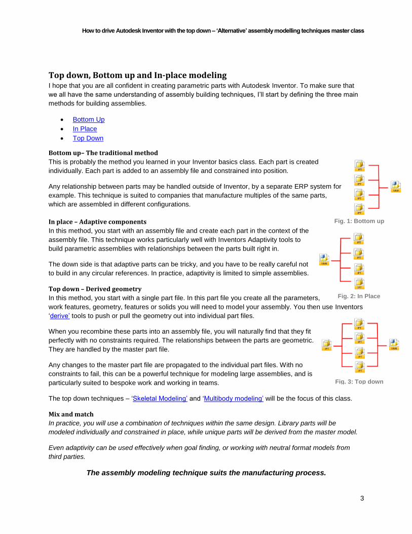
Bottom up– The traditional method
This is probably the method you learned in your Inventor basics class. Each part is created
individually. Each part is added to an assembly file and constrained into position.
Any relationship between parts may be handled outside of Inventor, by a separate ERP system for
example. This technique is suited to companies that manufacture multiples of the same parts,
which are assembled in different configurations.
In place – Adaptive components
In this method, you start with an assembly file and create each part in the context of the
assembly file. This technique works particularly well with Inventors Adaptivity tools to
build parametric assemblies with relationships between the parts built right in.
The down side is that adaptive parts can be tricky, and you have to be really careful not
to build in any circular references. In practice, adaptivity is limited to simple assemblies.
Top down – Derived geometry
In this method, you start with a single part file. In this part file you create all the parameters,
work features, geometry, features or solids you will need to model your assembly. You then use Inventors
‘derive’ tools to push or pull the geometry out into individual part files.
When you recombine these parts into an assembly file, you will naturally find that they fit
perfectly with no constraints required. The relationships between the parts are geometric.
They are handled by the master part file.
Any changes to the master part file are propagated to the individual part files. With no
constraints to fail, this can be a powerful technique for modeling large assemblies, and is
particularly suited to bespoke work and working in teams.
The top down techniques – ‘Skeletal Modeling’ and ‘Multibody modeling’ will be the focus of this class.
Mix and match
In practice, you will use a combination of techniques within the same design. Library parts will be
modeled individually and constrained in place, while unique parts will be derived from the master model.
Even adaptivity can be used effectively when goal finding, or working with neutral format models from
third parties.
The assembly modeling technique suits the manufacturing process.
Figure 1 Fig. 1: Bottom up
Fig. 2: In Place
Fig. 3: Top down

How to drive Autodesk Inventor with the top down – ‘Alternative’ assembly modelling techniques master class
4
Top down: Skeletal modeling ‘Skeletal’ modeling is the precursor of the more recent ‘Multi body Design Part’ technique that we will be
looking at next.
Using skeletal modeling, you create all the parameters, work features and geometry you will need in one
part file, and then use Inventor’s ‘Derive’ tools to pull this geometry into each part file of your assembly.
Finally you add 3D features at the part level.
Since the release of Inventor 2010, this technique has been given a massive boost with the additional
functions built around sketch blocks and the ‘Make components’ tool.
Sketch block layouts
Skeletal modeling is an excellent technique to use for Kinematic (moving) assemblies. 2D Sketch blocks
can be assembled with geometric constraints to prove out the function of a design before any 3D
modeling happens.
Using the ‘Make components’ tool, the sketch blocks can be pushed out into part files; Inventor will
automatically apply assembly constraints based on the geometric constraints from the skeletal model.
Once you have your design working, you can ‘flesh out’ your skeletal model, by creating 3D features in
the individual part files.
Workflow
Plan your assembly.
Add your known parameters.
Create work planes and other work features as required.
Create sketch blocks.
Constrain sketch blocks (within the context of a sketch) and get your design functioning.
Use the make components tool to derive your sketch blocks into an assembly.
Add 3D features to the individual files at the part level.
Pros and cons of skeletal modeling
Cons:
Working with just the geometry on its own is not very intuitive.
Building the part models from derived geometry can be time consuming.
Building the part models without context can mean lots of editing in the assembly model later.
Pros:
The derived parts are very lightweight
Assemblies can quickly be laid out in 2D to see how they function before time is invested in 3D
modeling.
How to drive Autodesk Inventor with the top down – ‘Alternative’ assembly modelling techniques master class
5
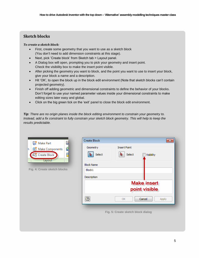
Sketch blocks
To create a sketch block:
First, create some geometry that you want to use as a sketch block
(You don’t need to add dimension constraints at this stage).
Next, pick ’Create block’ from Sketch tab > Layout panel.
A Dialog box will open, prompting you to pick your geometry and insert point.
Check the visibility box to make the insert point visible.
After picking the geometry you want to block, and the point you want to use to insert your block,
give your block a name and a description.
Hit ‘OK’, to open the block up in the block edit environment (Note that sketch blocks can’t contain
projected geometry).
Finish off adding geometric and dimensional constraints to define the behavior of your blocks.
Don’t forget to use your named parameter values inside your dimensional constraints to make
editing sizes later easy and global.
Click on the big green tick on the ‘exit’ panel to close the block edit environment.
Tip: There are no origin planes inside the block editing environment to constrain your geometry to.
Instead, add a fix constraint to fully constrain your sketch block geometry. This will help to keep the
results predictable.
Fig. 4: Create sketch blocks
Fig. 5: Create sketch block dialog

How to drive Autodesk Inventor with the top down – ‘Alternative’ assembly modelling techniques master class
6
The sketch blocks folder
You can see your newly created block definition in the browser tree in the ‘Blocks’ folder. Each instance
of the block can be seen in the sketch where it has been placed.
Placing a sketch block
Place an instance of your block by right clicking on the block definition and choosing ‘Place block’ (you
must be in the context of a sketch to place a block).You can edit the block at any point by right clicking on
the definition or the instance and choosing ‘edit block’.
Visibility of sketch blocks
Blocks have their own visibility status. Making the sketch invisible will make everything it contains
invisible. Within the sketch, individual block visibility can be turned on and off as you need it.
Nesting and flexibility of sketch blocks
Blocks can be nested, and just like assemblies, they can be made ‘flexible’ to allow you to apply
geometric constraints to control their motion.
Exploding sketch blocks
Right click on a block to explode it and return the geometry to your sketch.
Tip: To change the insert point, visibility of the insert point, block name, or block description, right click
within the block edit environment and chose ‘Block properties’. Geometry cannot be selected and you
must right-click off geometry to see the Block Properties option.
Check out the Inventor Wiki Help site for more on sketch blocks
Fig. 6: Sketch blocks in the feature browser
How to drive Autodesk Inventor with the top down – ‘Alternative’ assembly modelling techniques master class
7
Top Down: Multibody – Design part In the skeletal modeling technique, we limited ourselves to only defining the geometry we needed in our
design part; the 3D features are created later.
With the Multibody technique, we can go a step further. With the Multibody design part workflow we
define all the 3D features we need in the design part. Each part that is required for the assembly is
defined as a separate solid. When the design is complete, the separate solids can be derived out using
the ‘Make components’ tool.
The derived parts are grounded in the assembly file. The relationship between the parts is defined
geometrically, rather than by using assembly constraints. Any changes to the ‘Design’ part automatically
propagate through to the assembled parts.
Bespoke work
The Multibody workflow is excellent for bespoke work. Because you are designing the whole assembly
within one part file, you can build all your ‘parts’ (solids) in context, making sure that they all fit and work
with each other before you create an assembly model.
Because all the parameters, geometry, features and solids are held within one part file, you can build
reliable relationships between features without using adaptivity.
Workflow
Plan your assembly.
Add your known parameters.
Create work planes and other work features as required.
Create sketch blocks.
Create the geometry you need to define your design.
Model the 3D features, separating the features for each ‘part’ into solids.
Use the make components tool to derive your solids into an assembly.
Pros and cons of derived Multibody modeling
Cons:
Multibody design parts can quickly become huge, a structured approach is required.
Parts derived from a Multibody model can be large in file size.
Assemblies containing lots of derived parts can take a lot of computing power to update.
Pros:
An intuitive design technique.
Quick and easy to edit.
No assembly constraints means no constraints to fail.

How to drive Autodesk Inventor with the top down – ‘Alternative’ assembly modelling techniques master class
8
The Hybrid approach Of course, you don’t have to pick one technique or another. Skeletal modeling and Multibody design parts
can be combined with regular Inventor parts, iParts or even non parametric parts to complete your
assembly.
The iCopy tools use derived parts and adaptivity together for a powerful method of creating many
variations on a similar design.
Although an assembly model created by deriving parts in from a Multibody design part doesn’t need any
constraints, there’s no reason why you can un-ground parts and add constraints to show motion or
multiple positions.
Dividing a large or complex model up into separate Multibody parts, which are coordinated by a skeletal
model, can keep the complexity of each Multibody part model down.
Mixing up skeletal modeling and Multibody parts to collaborate with your chums
One of the great benefits of working with Autodesk Inventor (Against 2D CAD) is the ability to collaborate
on the design and modeling process. You can have multiple people working on the same model in real
time.
Scary thought? It’s not impossible – and it can completely revolutionize how your drawing office works.
Workflow
Plan your assembly.
Add your known parameters.
Create work planes and other work features as required.
Create sketch blocks.
Create the geometry you need to define your design.
Derive your ‘Master’ skeletal model into multiple parts files.
Each user models the 3D features for one area separating each ‘part’ out as a solid.
Bring together the ‘Design’ models into a preview assembly for cross checking and clash
detection.
Each user uses the make components tool to derive the solids into sub-assemblies.
Build the final assembly from the sub-assemblies.
Pros and cons of derived Hybrid modeling
Cons:
Your whole team needs to work in a structured and methodical manner
Pros:
The workload can be shared across the whole department

How to drive Autodesk Inventor with the top down – ‘Alternative’ assembly modelling techniques master class
9
Multi body parts Multi body (or Multi solid) parts are a new feature that was introduced with Inventor 2010. Creating
multiple bodies within a single part file is easy – but the controls are subtle, and easy to miss.
Creating a base solid
The first feature that you create in your part file will automatically create a new body. You can see this in
the feature tree under the ‘Solid bodies’ folder.
Any new feature that you add will automatically be added to this body– unless you ask Inventor to create
a new body!
Creating a new body
The option to create new solids can be found in the sketch based feature commands. Create a new body
in the Extrude, Revolve, Loft, Sweep, and Coil commands by selecting the ‘New Solid’ option in the dialog
box. You can also use the spit command to divide a single body in two.
Note: If you forget to hit ‘new solid’, don’t worry. You can go back and edit your feature at any time to turn
it into a solid. However, this doesn’t work the other way. You can’t turn a solid back into a feature – so
watch out!
Check out the Inventor Wiki help site for more on Multi body part modeling
Fig. 7: Make a new solid
Fig. 8: Make a new solid - in canvas

How to drive Autodesk Inventor with the top down – ‘Alternative’ assembly modelling techniques master class
10
Picking between bodies
As soon as you have multiple bodies, you will need to choose which body to add your new features to. By
default, Inventor will add your new feature to the last solid you created. Use the ‘Solids’ button to add your
feature to a different solid.
Sorting the feature tree
You will notice that your features are nicely organized under their bodies in the solid bodies folder, as well
as being shown in their usual place in the feature tree.
However, you might find that you can’t re-order your solid bodies. The order of the solid bodies in the
solid bodies’ folder tree directly relates to the order of the features in the feature tree.
To sort your bodies folder, you need to sort your feature tree. Drag the primary feature that the solid is
based on up and down the tree. The solids in the solid bodies folder will update automagically.
Working with bodies
Cut features can run across multiple solids, making it easy to coordinate cut extrudes and holes between
solids/derived parts.
Solid bodies can be moved and rotated independently of each other. Bodies can also be used for
Boolean operations such as join, intersect or cut.
Bodies can be made invisible, independently of the other bodies in the part file.
Fig. 9: Pick a solid
Fig. 10: Pick a solid - in canvas

How to drive Autodesk Inventor with the top down – ‘Alternative’ assembly modelling techniques master class
11
Multibody workflow tips Multibody parts are by their nature feature rich. They can quickly run in to tens or even hundreds of
solids, and it is imperative that you work in a structured manner for predictable results.
The tips outlined below will help you to minimize the number of cross feature relationships that you build,
and maximize the flexibility of your Multibody models.
The aim is to be able to drag the collection of features that represent a part up or down the feature tree
without mangling your model.
You don’t have to follow these tips in the order below. For example, you can go back and add parameters
and work features later in the process. However, following this structured approach will help you to work
in a productive manner.
Named parameters
Before you even start modeling, plan your process. Analyze the design concept that you are modeling
and look for dimensions that define the design. Add these dimensions as named parameters, and refer
back to your named parameters wherever possible.
Suggestions include the overall width, depth and height of the design. Distances to datums and grids.
Material thicknesses, draft angles, tolerances and limits. Check the ‘export’ box in the parameters
manager to make sure that any coordinating parameters are available to be derived out to the part files.
Tip: Use the named parameter description field to remind yourself and your colleagues of what each
parameter is doing.
Fig. 11: The parameters manager

How to drive Autodesk Inventor with the top down – ‘Alternative’ assembly modelling techniques master class
12
Work features
Use your named parameter values to create Work Planes to represent your Grid and Datum lines, along
with any other work features you will need to coordinate your model.
Tip: When building Multibody parts it can reduce flexibility to use the origin planes. Instead ‘Overlay’ the
origin planes with your own work planes set to an offset of 0. This will allow you to make adjustments
later.
Defining geometry
Create some sketches on your work planes, referring to your named parameters, to define the overall
width, depth and height of your design. Use construction geometry and constrain all of these sketches to
the origin (or your own datum point).
Use these sketches as the structure to ‘hang’ the rest of your sketches upon.
Sketches
Keep it simple; keep it simple – KEEP IT SIMPLE.
When part modeling, creating only one closed profile loop in each sketch is recommended. By its nature
you will want to use sketches with multiple closed loops to coordinate features in your Multibody design
parts. This can be the source of most of your problems when editing Multibody parts.
Don’t create sketches on features. Use your work features instead.
Look for opportunities to split your profiles over multiple sketches.
Keep projected geometry to a minimum – use your named parameters and construction geometry
to coordinate sketches.
Use sketch blocks wherever possible.
Don’t let Inventor ‘over constrain’ your sketches.
Tip: Make use of ‘Constraint persistence’ to turn off automatic constraints when you need to be certain of
what constraints are being added. You can quickly toggle constraint persistence off by holding down the
CTRL key while sketching.
Sketch Blocks
If you need to use the same profile in multiple areas, create this profile as a sketch block. Don’t forget to
link your sketch blocks to your named parameters for easy adjustment later.
Feature modeling
Don’t put every feature into your design model. Look for opportunities to put ‘secondary’ features that
don’t need to be coordinated in your design model (such as fillets and chamfers) into the individual part
files. You can coordinate the dimensions of these features by deriving your named parameters into the
part.
Library features
Multibody parts can be ‘assembled’ using iFeatures. If you are regularly adding the same features to your
Multibody design parts, consider saving them out as iFeatures and adding them to your iFeature gallery.

How to drive Autodesk Inventor with the top down – ‘Alternative’ assembly modelling techniques master class
13
‘Flexing’ the design part
If you are building your design around parameters that you are confident will change (After all, this is why
you are using Inventor – right?) ‘Flex’ your design part regularly to check for any cross feature
relationships that might fail.
Fix failures now before you build another 101 solids that rely on your base geometry!
Breaking it down
Look for opportunities to break your design model down into smaller chunks by creating derived parts
which contain the coordinating geometry only. Model up each multi body sub-part in context, and then
bring all the design parts back into an assembly for checking before you derive out your parts into
assemblies.
Sorting the feature tree
Keeping your main coordinating sketches bunched together at the top of the
tree can make editing the design part later much more intuitive. Place any
secondary sketches immediately before the features that they are controlling.
Naming features
Name all your sketches, primary features and solids as you go. Don’t forget
that it might be YOU who has to come back and edit this model in 6 months’
time. Make it easy to see which work features and sketches are controlling
which features.
Tip: Feature names must be unique. I suggest that you suffix the feature
name with the feature type to help you see which features are related.
Automating the prefix and suffix
The ‘Make components’ tool will automatically pick up the names of your
solids to use as part names. You can change this in the make components’
Dialog box if you want.
Tip: Check out this special secret setting which you can use to ask Inventor to
automatically add a prefix or suffix to your solid name when creating parts.
Get the code: You can also use this iLogic code to rename your solids before deriving them into parts.
Materials and templates
Each part file can only contain one material. You could change the appearance of each individual solid in
the design part, but I don’t recommend it. Instead, allocate materials and appearances to the individual
derived parts.
Allocating appearances in derived parts will override the appearance setting in the part file. Check out this
link for advice in dealing with this issue. Default setting for the option “Use color override from source
component” in the Derive Part dialog.
Fig. 12: Example feature naming

How to drive Autodesk Inventor with the top down – ‘Alternative’ assembly modelling techniques master class
14
The ‘Make components’ tool allows you to pick individual template files for each solid that you are
deriving. Creating and using template files which represent your commonly used materials will save you
hours.
Deriving the whole enchilada
The Make components tool can be used to derive sketches, sketch blocks, work features solids and even
parameters into your part files. Don’t forget to click the ‘Include parameters’ button!
Editing Multibody models
Even after you have taken all of these precautions, editing a complex, feature rich Multibody design part
can be a headache.
If you need to edit work features, sketches or features near the top of the feature tree – roll the end of part
marker (EOP) up underneath the feature or sketch before you edit it. After you have made the change,
roll the EOP down again a few features at a time and fix any problems as you go.
Tip: DON’T flip back to the assembly with the EOP rolled up. The solids in your design part will be
suppressed, and all the derived parts in the assembly will fail. This is an annoyance but getting them back
is easy. Go back to the design part and roll the EOP back down, then flip back to your assembly and
update.

How to drive Autodesk Inventor with the top down – ‘Alternative’ assembly modelling techniques master class
15
‘Pulling’ geometry with the Derive tool The ‘traditional’ method of deriving geometry into part
files is to ‘pull’ the geometry through using Inventor’s
‘Derive’ tool.
This has largely been superseded by the ‘Make part’
and ‘Make component’ tools, but it’s still a technique
worth knowing about.
You will find the derive tool on the Manage tab > Insert
panel.
Workflow
Create a new part
Close and delete the default base sketch
Click on the ‘Derive’ tool
From the file open Dialog, pick a part or
assembly that you wish to derive from
From the Derived part Dialog pick the solids,
surfaces, 2D & 3D sketches, sketch blocks,
work features or parameters that you want to
derive into your new part
Note that you can mirror the geometry as it
comes in
Hit OK to complete the process
Tip: You can speed up the building of multiple part files from skeletal geometry by temporarily saving this
IPT as a template file.
Fig. 13: The Derive tool
Fig. 14: Creating or editing a Derived part
How to drive Autodesk Inventor with the top down – ‘Alternative’ assembly modelling techniques master class
16
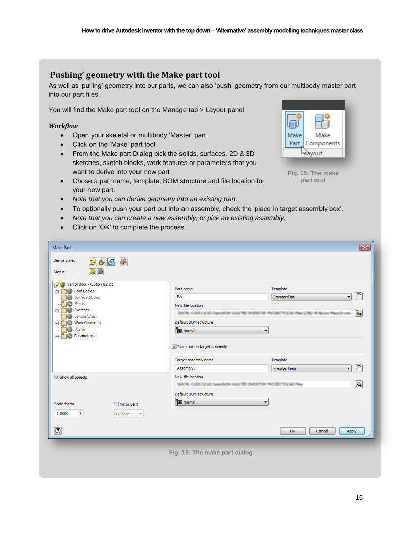
‘Pushing’ geometry with the Make part tool As well as ‘pulling’ geometry into our parts, we can also ‘push’ geometry from our multibody master part
into our part files.
You will find the Make part tool on the Manage tab > Layout panel
Workflow
Open your skeletal or multibody ‘Master’ part.
Click on the ‘Make’ part tool
From the Make part Dialog pick the solids, surfaces, 2D & 3D
sketches, sketch blocks, work features or parameters that you
want to derive into your new part
Chose a part name, template, BOM structure and file location for
your new part.
Note that you can derive geometry into an existing part.
To optionally push your part out into an assembly, check the ‘place in target assembly box’.
Note that you can create a new assembly, or pick an existing assembly.
Click on ‘OK’ to complete the process.
Fig. 15: The make part tool
Fig. 16: The make part dialog

How to drive Autodesk Inventor with the top down – ‘Alternative’ assembly modelling techniques master class
17
‘Pushing’ out multiple derived parts with the ‘Make components’ tool. The Make components tool automates the process of deriving out multiple
bodies into multiple parts, subassemblies and assemblies. It is a powerful
tool and a real time saver.
However, like any process you will want to make sure that you get the first
one right before you go into mass production. I recommend that you
experiment with a small section of your assembly and get it right before you
go spitting out hundreds of parts.
You will find the Make part tool on the Manage tab > Layout panel
Workflow
Open your multibody master part
Check that your named parameters are available for export, save if necessary
Click on the ‘Make component’ tool
From the Make components: selection Dialog, pick the solids that you want to derive
Optionally choose to derive your parts into an assembly
Note that you can derive your parts into an existing assembly
Click the ‘next’ button to move onto the Make components: Bodies Dialog
Note that you can go back to the Selection Dialog at any time with the ‘<<Return to selection’
button (Cont’ on next page)
Fig. 17: The make components tool
Fig. 18: The make components - Selection dialog
How to drive Autodesk Inventor with the top down – ‘Alternative’ assembly modelling techniques master class
18
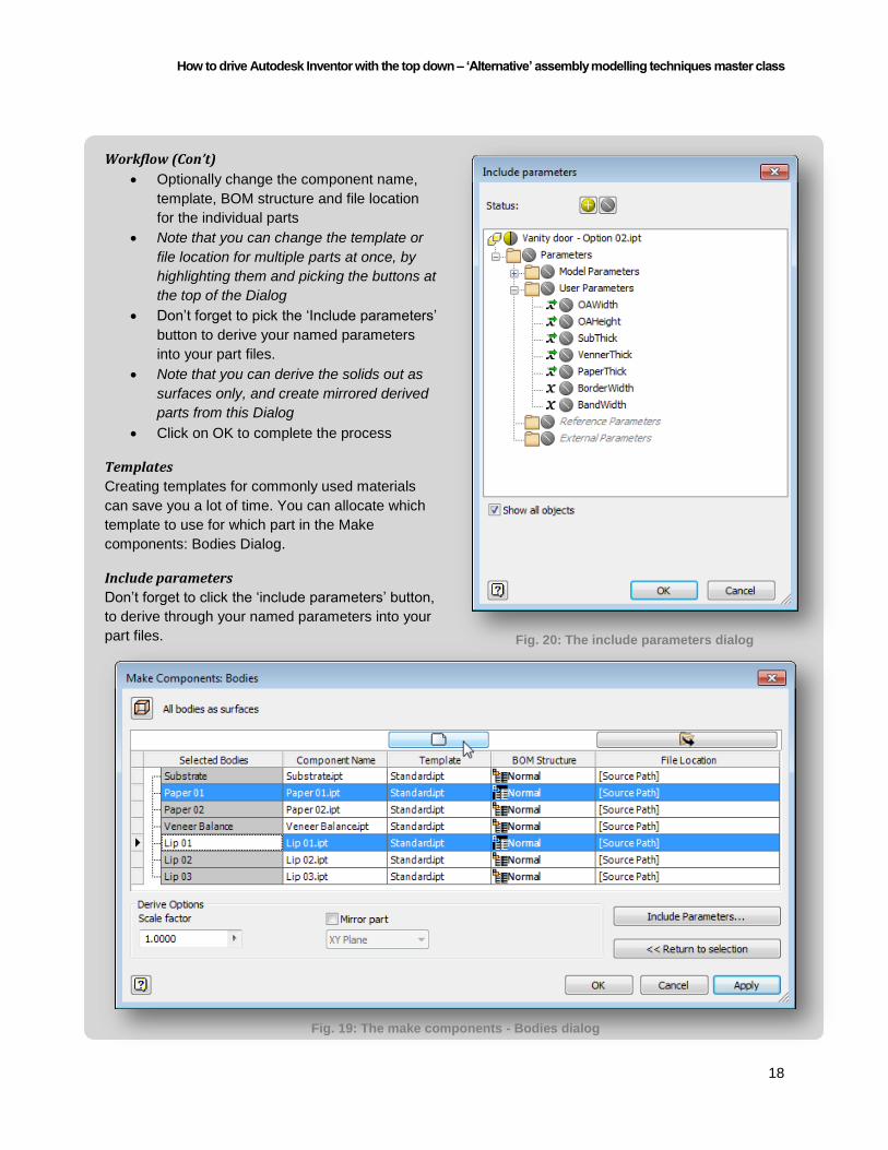
Workflow (Con’t)
Optionally change the component name,
template, BOM structure and file location
for the individual parts
Note that you can change the template or
file location for multiple parts at once, by
highlighting them and picking the buttons at
the top of the Dialog
Don’t forget to pick the ‘Include parameters’
button to derive your named parameters
into your part files.
Note that you can derive the solids out as
surfaces only, and create mirrored derived
parts from this Dialog
Click on OK to complete the process
Templates
Creating templates for commonly used materials
can save you a lot of time. You can allocate which
template to use for which part in the Make
components: Bodies Dialog.
Include parameters
Don’t forget to click the ‘include parameters’ button,
to derive through your named parameters into your
part files. Fig. 20: The include parameters dialog
Fig. 19: The make components - Bodies dialog
How to drive Autodesk Inventor with the top down – ‘Alternative’ assembly modelling techniques master class
19
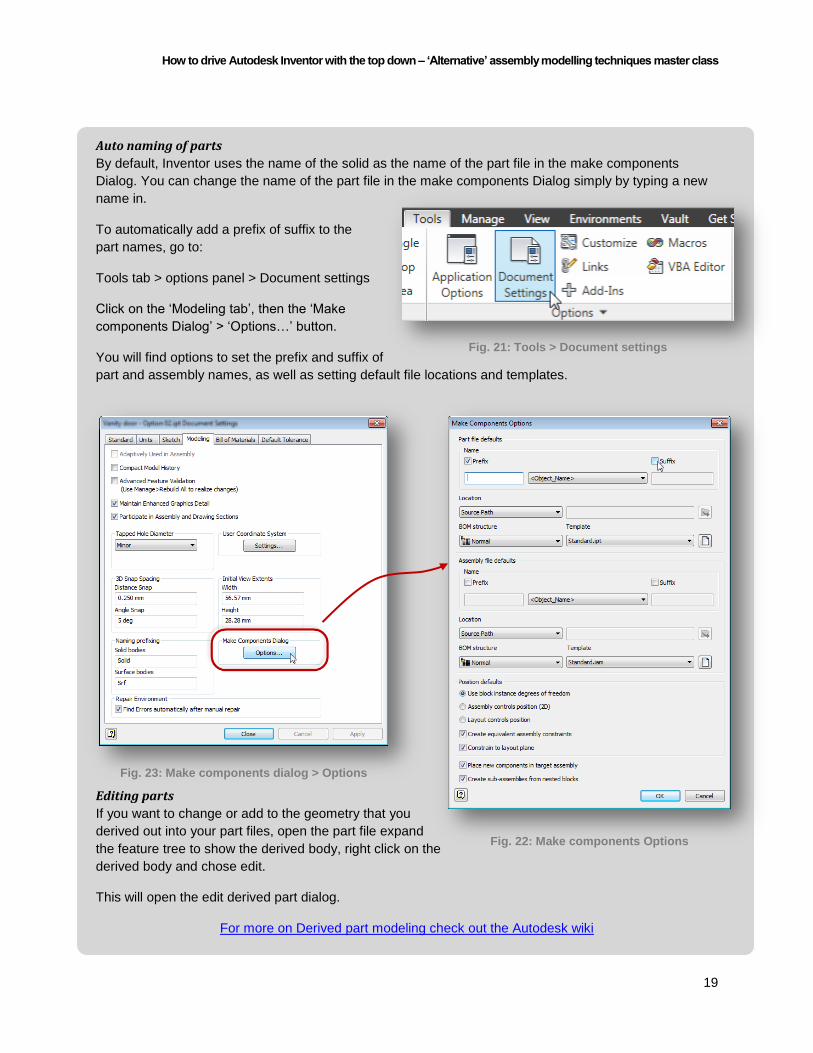
Auto naming of parts
By default, Inventor uses the name of the solid as the name of the part file in the make components
Dialog. You can change the name of the part file in the make components Dialog simply by typing a new
name in.
To automatically add a prefix of suffix to the
part names, go to:
Tools tab > options panel > Document settings
Click on the ‘Modeling tab’, then the ‘Make
components Dialog’ > ‘Options…’ button.
You will find options to set the prefix and suffix of
part and assembly names, as well as setting default file locations and templates.
Editing parts
If you want to change or add to the geometry that you
derived out into your part files, open the part file expand
the feature tree to show the derived body, right click on the
derived body and chose edit.
This will open the edit derived part dialog.
For more on Derived part modeling check out the Autodesk wiki
Fig. 21: Tools > Document settings
Fig. 23: Make components dialog > Options
Fig. 22: Make components Options

How to drive Autodesk Inventor with the top down – ‘Alternative’ assembly modelling techniques master class
20
Tips on large assembly models with master parts Large and complex assemblies have their own considerations. Any advice you ever read on managing
large assemblies applies to assemblies derived from design parts too.
Here are a few tips that specifically apply to the derived part workflow.
Don’t go Multibody mad
Don’t put every part that you need into your design model. Look out for opportunities to build Library parts
such as hardware and fixings in the traditional manner. Using library parts and iParts will speed up your
design process.
Use feature based parametric design sparingly
This one is counterintuitive. We are using Inventor because we want a parametric design tool – right? But
think about it; do you have library parts that represent items you buy in from outside the company? Do
they really need to be parametric?
Even if you design these parts in Inventor, saving out and using a copy in a neutral file format can really
bring the complexity of your assembly models down.
Keep it simple
Keep each part as simple as possible, particularly for parts that you won’t be manufacturing in house.
That 0.1 fillet on all the edges might be technically accurate, but if you are not manufacturing the part, you
don’t need that information.
Not only will simplifying your library parts speed up your assembly model, but it will also speed up your
drawings, and prevent your drawings being cluttered up with feature lines that aren’t required.
Keep it simple (Again)
Don’t create features or solids in your multibody design parts that represent the same part in different
locations. Instead use the same part in your assembly multiple times and constrain it into position. If you
can - patterning parts in assemblies rather than copying them is even less taxing on Inventor.
Tip: The make components tool has an option to Mirror solids as you derive them into parts.
Use Inventor for what it’s good at
Don’t create holes in the design part for features such as bolts. Instead, create sketch geometry in your
master part to define the hole center, derive the hole center through to the part, and use the bolted
connection generator to add the hole and bolt in one swift move.
You can also mix and match design parts with the frame generator in a similar fashion.

How to drive Autodesk Inventor with the top down – ‘Alternative’ assembly modelling techniques master class
21
Faster updates
The advantage of creating an assembly model based
on the same design part is that changes to the design
part will automatically propagate to all the parts
derived from it.
The disadvantage is that Inventor will check every
single derived part in your assembly for changes
whenever you save your design part – even if you
didn’t make any edits to the design part. Depending
on the size and complexity of your assembly and the
power of your computer, this could add a long time to
your design process.
One way to speed up the process is to suppress the
link between the derived parts and the design part.
Don’t forget to un-suppress the links when you
actually want changes to your design part to
propagate through!
Check out this iLogic code to suppress all the links at
once.
In conclusion I hope that you come away from this presentation with a renewed enthusiasm for building your
parametric design models with Autodesk Inventor. It is said that you don’t know what you don’t
know. But now you know. So go away and build!
Credits Thanks very much to Scott Moyse and John Evans of DesignandMotion.net, Jon Landeros of Inventor
tales and Curtis Waguespack of Inventor from The trenches for their contributions (Any mistakes are my
own!).
Thanks the Gary Edwards of Adris professional services for loaning me a laptop to run the presentation
on.
Finally thanks very much to my bosses at Halstock Cabinet makers, Richard, Roger and Jasper, for their
support, and thanks to the rest of the CAD team at Halstock for being my guinea pigs.
References For more on Autodesk Inventor and derived modeling techniques: Cadsetterout.com - Assembly techniques for woodworkers Designandmotion.net - Top down design with Inventor Inventor-tales.blogspot.co.uk - Tips for multibody part modeling Opendesignproject.org - A very detailed tutorial on derived part modeling Blogs.rand.com - A great starter tutorial on multibody part modeling Wikihelp.autodesk.com - The Inventor Wiki page for top down design Inventortrenches.blogspot.co.uk - Tips on iLogic and multibody parts
Fig. 24: Suppressing links in derived parts

How to drive Autodesk Inventor with the top down – ‘Alternative’ assembly modelling techniques master class
22
Appendix A – Get the code!
Thanks to Curtis Waguespack author of ‘Mastering Autodesk Inventor’ and writer of Inventor from The
trenches for sharing this iLogic code.
Suppress derived part links
One disadvantage of the derived part technique is that Inventor will check the master part for updates
from every part in the assembly that contains a link.
This code temporarily suppresses the link to speed up your assembly updates. Don’t forget to un-
suppress the link when you want the whole assembly to update!
'--Suppress the link to a master part---
'-------Code by Curtis Waguespack-------
'http://Inventortrenches.blogspot.co.uk/
oSuppress_YN = InputRadioBox("Select an option", "Suppress Derived Links",
"Un-Suppress Derived Links", True, "iLogic")
' Get the top level assembly document
Dim oDoc As AssemblyDocument
oDoc = ThisApplication.ActiveDocument
' Set a reference to the assembly component definition
Dim oComp As AssemblyComponentDefinition
oComp = oDoc.ComponentDefinition
' Loop each component occurrence to get its document
Dim oOcc As ComponentOccurrence
For Each oOcc In oComp.Occurrences
Dim oPartDoc As Document
oPartDoc = oOcc.Definition.Document
If TypeOf oPartDoc Is PartDocument Then
' Set a reference to the part component definition
Dim oPartComp As PartComponentDefinition
oPartComp = oPartDoc.ComponentDefinition
' Loop each derived part component in this part document
Dim oDerPartComp As DerivedPartComponent
For Each oDerPartComp In oPartComp.ReferenceComponents.DerivedPartComponents
oDerPartComp.SuppressLinkToFile = oSuppress_YN
Next
End If
Next
------- end of ilogic ------

How to drive Autodesk Inventor with the top down – ‘Alternative’ assembly modelling techniques master class
23
Ground components
If you are using the Make components tool, Inventor will automatically ground your components about the
origin for you. Alternatively you could use the Assembly bonus tool ‘Ground and root component’.
This code will ground your components around the origin, without adding additional assembly constraints.
Tip: To add large numbers of parts to an assembly without having to pick an insert point, drag and drop
the parts into Inventor from windows explorer.
'---------Ground all components---------
'-------Code by Curtis Waguespack-------
'http://Inventortrenches.blogspot.co.uk/
' set a reference to the assembly component definintion.
' This assumes an assembly document is open.
Dim oAsmCompDef As AssemblyComponentDefinition
oAsmCompDef = ThisApplication.ActiveDocument.ComponentDefinition
'Iterate through all of the occurrences
Dim oOccurrence As ComponentOccurrence
For Each oOccurrence In oAsmCompDef.Occurrences
'check for and skip virtual components
'(in case a virtual component trips things up)
If Not TypeOf oOccurrence.Definition Is VirtualComponentDefinition Then
'set a reference to the transient geometry object
oTG = ThisApplication.TransientGeometry
'set the occurence rotation and translation to 0,0,0
oOccurrence.Transformation = oTG.CreateMatrix
'ground each occurence
oOccurrence.Grounded = True
Else
End If
Next
iLogicVb.UpdateWhenDone = True
------- end of ilogic ------

How to drive Autodesk Inventor with the top down – ‘Alternative’ assembly modelling techniques master class
24
Rename all solid bodies
This code allows you to rename all the solids in your multibody part using a prefix. When you press the
OK button the rule renames each solid body using the prefix and an increment number, adding
a leading zero for each number less than 10.
'---------Rename all solid bodies-------
'-------Code by Curtis Waguespack-------
'http://Inventortrenches.blogspot.co.uk/
'check for custom iProperty and add it if not found Dim prefix As String = "Prefix" customPropertySet = ThisDoc.Document.PropertySets.Item _ ("Inventor User Defined Properties") Try prop= customPropertySet.Item(prefix) Catch ' Assume error means not found customPropertySet.Add("", prefix) End Try 'write the part number to the Prefix iProperty if it is empty if iProperties.Value("Custom", "Prefix") = "" Then iProperties.Value("Custom", "Prefix") = iProperties.Value("Project", "Part Number") & "_" else end if 'check that this active document is a part file Dim partDoc As PartDocument If ThisApplication.ActiveDocument.DocumentType <> kPartDocumentObject Then MessageBox.Show ("Please open a part document", "iLogic") End If 'define the active document partDoc = ThisApplication.ActiveDocument Dim solid As SurfaceBody Dim i As Integer 'get input from user prefix = InputBox("Enter a prefix for the solid body names", "iLogic", iProperties.Value("Custom", "Prefix")) 'write input back to custom iProperty iProperties.Value("Custom", "Prefix") = prefix i = 1 'rename all solid bodies incrementing suffix For Each solid In partDoc.ComponentDefinition.SurfaceBodies solid.Name = prefix + IIf(i < 10, "0" + CStr(i), CStr(i)) i = i + 1 Next ------- end of ilogic ------