Embed Size (px)
Citation preview
WT-1
ROAD WHEELS & TIRES
E SUSPENSION
CONTENTS
C
D
F
G
H
I
J
K
L
M
SECTION WTA
B
WT
Revision: 2004 April 2002 Q45
ROAD WHEELS & TIRES
PREPARATION ........................................................... 2Special Service Tools ............................................... 2Commercial Service Tools ........................................ 2
NOISE, VIBRATION AND HARSHNESS (NVH) TROUBLESHOOTING ................................................ 3
NVH Troubleshooting Chart ..................................... 3ROAD WHEEL ............................................................ 4
Inspection ................................................................. 4ALUMINUM WHEEL ............................................. 4STEEL WHEEL ..................................................... 4
ROAD WHEEL TIRE ASSEMBLY .............................. 5Balancing Wheels (Bonding Weight Type) ............... 5
REMOVAL ............................................................. 5WHEEL BALANCE ADJUSTMENT ...................... 5
Rotation .................................................................... 6LOW TIRE PRESSURE WARNING SYSTEM ............ 7
System Components ................................................ 7System Description .................................................. 7
TRANSMITTER ..................................................... 7ANTENNA ............................................................. 7TIRE PRESSURE WARNING CONTROL UNIT ..... 8DISPLAY ............................................................... 8
TROUBLE DIAGNOSES ............................................ 9Wiring Diagram ........................................................ 9ID Registration Procedure ...................................... 13
ID REGISTRATION WITH TRANSMITTER ACTIVATION TOOL ............................................ 13ID REGISTRATION WITHOUT TRANSMITTER ACTIVATION TOOL ............................................ 13
Self-Diagnosis ........................................................ 14DESCRIPTION .................................................... 14FUNCTION .......................................................... 14CONSULT-II ........................................................ 14
How to Perform Trouble Diagnosis for Quick and Accurate Repair ..................................................... 15
INTRODUCTION ................................................. 15WORK FLOW ...................................................... 16
Preliminary Check .................................................. 17Malfunction Code/Symptom Chart .......................... 18
TROUBLE DIAGNOSIS FOR SELF-DIAGNOSTIC ITEMS ........................................................................ 19
Inspection 1: Transmitter or Low Tire Pressure Warning Control Unit .............................................. 19
MALFUNCTION CODE NO. 21, 22, 23 OR 24 ... 19Inspection 2: Transmitter ........................................ 19
MALFUNCTION CODE NO. 31, 32, 33, 34, 35, 36, 37, 38, 41, 42, 43, 44, 45, 46, 47 OR 48 ....... 19
Inspection 3: Low Tire Pressure Warning Control Unit ......................................................................... 19
MALFUNCTION CODE NO. 51 ........................... 19TROUBLE DIAGNOSIS FOR SYMPTOMS .............. 20
Inspection 1: Warning Lamp Does Not Come On When Ignition Switch Is Turned On. ....................... 20Inspection 2: Warning Lamp Stays On When Ignition Switch Is Turned On. .............................................. 20Inspection 3: Warning Lamp Blinks When Ignition Switch Is Turned On. .............................................. 21Inspection 4: Hazard Warning Lamp Blinks When Ignition Switch Is Turned On. ................................. 22Inspection 5: “TIRE PRESSURE” Information In Display Does Not Exist. .......................................... 22Inspection 6: ID Registration Can Not Be Completed ... 23
REMOVAL AND INSTALLATION ............................. 24Transmitter ............................................................. 24
REMOVAL ........................................................... 24INSTALLATION ................................................... 24
SERVICE DATA ........................................................ 26Road Wheel ............................................................ 26Tire ......................................................................... 26
WT-2
PREPARATION
Revision: 2004 April 2002 Q45
PREPARATION PFP:00002
Special Service Tools EES000CZ
The actual shapes of Kent-Moore tools may differ from those of special service tools illustrated here.
Commercial Service Tools EES000N6
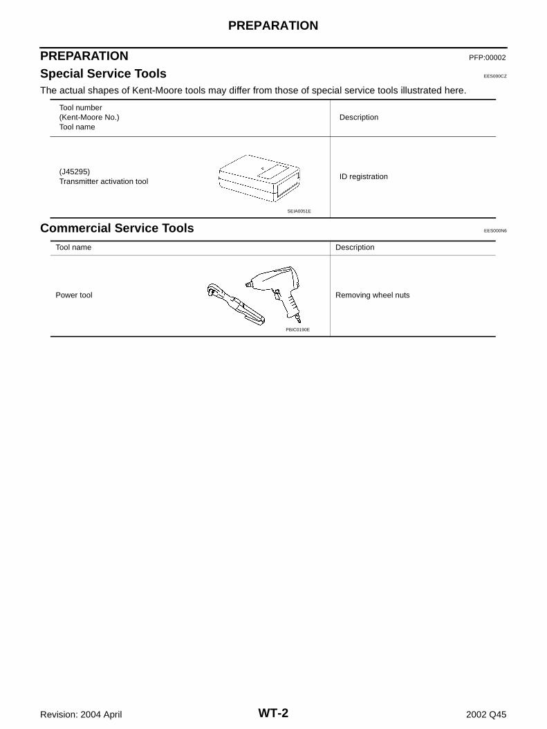
Tool number (Kent-Moore No.)Tool name
Description
(J45295)Transmitter activation tool
ID registration
SEIA0051E
Tool name Description
Power tool Removing wheel nuts
PBIC0190E
NOISE, VIBRATION AND HARSHNESS (NVH) TROUBLESHOOTING
WT-3
C
D
F
G
H
I
J
K
L
M
A
B
WT
Revision: 2004 April 2002 Q45
NOISE, VIBRATION AND HARSHNESS (NVH) TROUBLESHOOTING PFP:00003
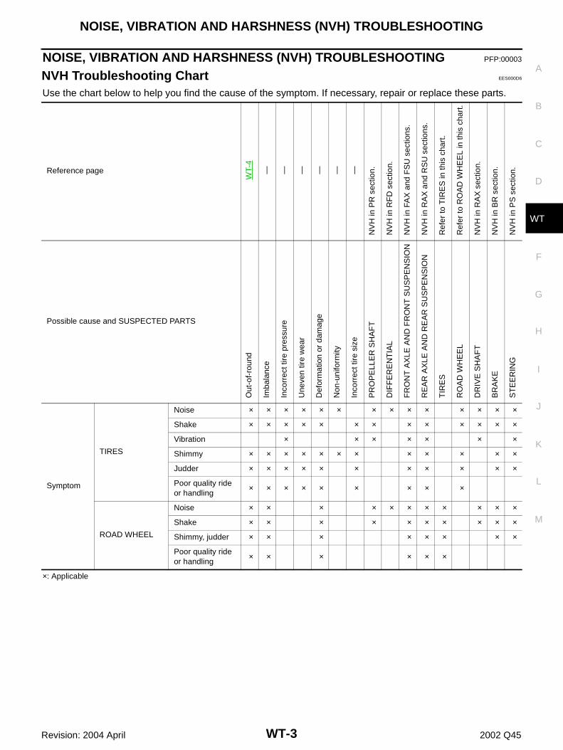
NVH Troubleshooting Chart EES000D6
Use the chart below to help you find the cause of the symptom. If necessary, repair or replace these parts.
×: Applicable
Reference page
WT-
4
— — — — — —
NV
H in
PR
sec
tion.
NV
H in
RF
D s
ectio
n.
NV
H in
FA
X a
nd F
SU
sec
tions
.
NV
H in
RA
X a
nd R
SU
sec
tions
.
Ref
er to
TIR
ES
in th
is c
hart
.
Ref
er to
RO
AD
WH
EE
L in
this
cha
rt.
NV
H in
RA
X s
ectio
n.
NV
H in
BR
sec
tion.
NV
H in
PS
sec
tion.
Possible cause and SUSPECTED PARTS
Out
-of-
roun
d
Imba
lanc
e
Inco
rrec
t tire
pre
ssur
e
Une
ven
tire
wea
r
Def
orm
atio
n or
dam
age
Non
-uni
form
ity
Inco
rrec
t tire
siz
e
PR
OP
ELL
ER
SH
AF
T
DIF
FE
RE
NT
IAL
FR
ON
T A
XLE
AN
D F
RO
NT
SU
SP
EN
SIO
N
RE
AR
AX
LE A
ND
RE
AR
SU
SP
EN
SIO
N
TIR
ES
RO
AD
WH
EE
L
DR
IVE
SH
AF
T
BR
AK
E
ST
EE
RIN
G
Symptom
TIRES
Noise × × × × × × × × × × × × × ×
Shake × × × × × × × × × × × × ×
Vibration × × × × × × ×
Shimmy × × × × × × × × × × × ×
Judder × × × × × × × × × × ×
Poor quality ride or handling
× × × × × × × × ×
ROAD WHEEL
Noise × × × × × × × × × × ×
Shake × × × × × × × × × ×
Shimmy, judder × × × × × × × ×
Poor quality ride or handling
× × × × × ×
WT-4
ROAD WHEEL
Revision: 2004 April 2002 Q45
ROAD WHEEL PFP:40300
Inspection EES000D1
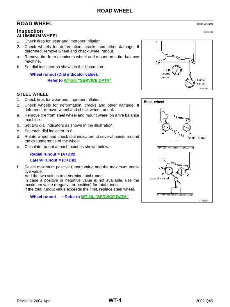
ALUMINUM WHEEL1. Check tires for wear and improper inflation.2. Check wheels for deformation, cracks and other damage. If
deformed, remove wheel and check wheel runout.a. Remove tire from aluminum wheel and mount on a tire balance
machine.b. Set dial indicator as shown in the illustration.
STEEL WHEEL1. Check tires for wear and improper inflation.2. Check wheels for deformation, cracks and other damage. If
deformed, remove wheel and check wheel runout.a. Remove tire from steel wheel and mount wheel on a tire balance
machine.b. Set two dial indicators as shown in the illustration.c. Set each dial indicator to 0.d. Rotate wheel and check dial indicators at several points around
the circumference of the wheel.e. Calculate runout at each point as shown below.
f. Select maximum positive runout value and the maximum nega-tive value.Add the two values to determine total runout.In case a positive or negative value is not available, use themaximum value (negative or positive) for total runout.If the total runout value exceeds the limit, replace steel wheel.
Wheel runout (Dial indicator value):Refer to WT-26, "SERVICE DATA"
SFA975B
Radial runout = (A+B)/2Lateral runout = (C+D)/2
Wheel runout : Refer to WT-26, "SERVICE DATA"SFA981B
ROAD WHEEL TIRE ASSEMBLY
WT-5
C
D
F
G
H
I
J
K
L
M
A
B
WT
Revision: 2004 April 2002 Q45
ROAD WHEEL TIRE ASSEMBLY PFP:40300
Balancing Wheels (Bonding Weight Type) EES000QX
REMOVAL1. Remove inner and outer balance weights from the road wheel.
CAUTION:Be careful not to scratch the road wheel during removal.
2. Using releasing agent, remove double-faced adhesive tape from the road wheel.CAUTION:● Be careful not to scratch the road wheel during removal.● After removing double-faced adhesive tape, wipe clean traces of releasing agent from the road
wheel.
WHEEL BALANCE ADJUSTMENT ● If a tire balance machine has adhesion balance weight mode settings and drive-in weight mode setting,
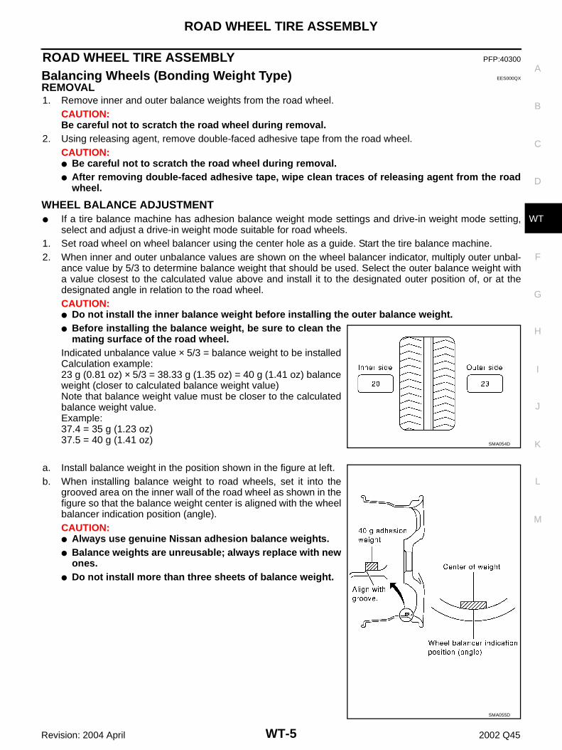
select and adjust a drive-in weight mode suitable for road wheels.1. Set road wheel on wheel balancer using the center hole as a guide. Start the tire balance machine.2. When inner and outer unbalance values are shown on the wheel balancer indicator, multiply outer unbal-
ance value by 5/3 to determine balance weight that should be used. Select the outer balance weight witha value closest to the calculated value above and install it to the designated outer position of, or at thedesignated angle in relation to the road wheel.CAUTION:● Do not install the inner balance weight before installing the outer balance weight.● Before installing the balance weight, be sure to clean the
mating surface of the road wheel.Indicated unbalance value × 5/3 = balance weight to be installedCalculation example:23 g (0.81 oz) × 5/3 = 38.33 g (1.35 oz) = 40 g (1.41 oz) balanceweight (closer to calculated balance weight value)Note that balance weight value must be closer to the calculatedbalance weight value.Example:37.4 = 35 g (1.23 oz)37.5 = 40 g (1.41 oz)
a. Install balance weight in the position shown in the figure at left.b. When installing balance weight to road wheels, set it into the
grooved area on the inner wall of the road wheel as shown in thefigure so that the balance weight center is aligned with the wheelbalancer indication position (angle).CAUTION:● Always use genuine Nissan adhesion balance weights.● Balance weights are unreusable; always replace with new
ones.● Do not install more than three sheets of balance weight.
SMA054D
SMA055D
WT-6
ROAD WHEEL TIRE ASSEMBLY
Revision: 2004 April 2002 Q45
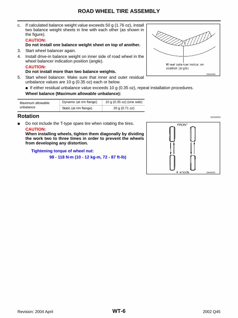
c. If calculated balance weight value exceeds 50 g (1.76 oz), installtwo balance weight sheets in line with each other (as shown inthe figure).CAUTION:Do not install one balance weight sheet on top of another.
3. Start wheel balancer again.4. Install drive-in balance weight on inner side of road wheel in the
wheel balancer indication position (angle).CAUTION:Do not install more than two balance weights.
5. Start wheel balancer. Make sure that inner and outer residualunbalance values are 10 g (0.35 oz) each or below.● If either residual unbalance value exceeds 10 g (0.35 oz), repeat installation procedures.Wheel balance (Maximum allowable unbalance):
Rotation EES000D5
● Do not include the T-type spare tire when rotating the tires.CAUTION:When installing wheels, tighten them diagonally by dividingthe work two to three times in order to prevent the wheelsfrom developing any distortion.
Maximum allowable unbalance
Dynamic (at rim flange) 10 g (0.35 oz) (one side)
Static (at rim flange) 20 g (0.71 oz)
SMA056D
Tightening torque of wheel nut:98 - 118 N·m (10 - 12 kg-m, 72 - 87 ft-lb)
SMA829C
LOW TIRE PRESSURE WARNING SYSTEM
WT-7
C
D
F
G
H
I
J
K
L
M
A
B
WT
Revision: 2004 April 2002 Q45
LOW TIRE PRESSURE WARNING SYSTEM PFP:40300
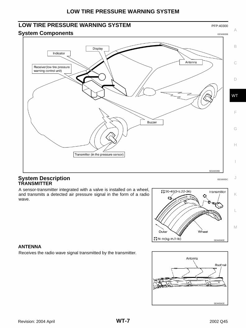
System Components EES000DB
System Description EES000DC
TRANSMITTERA sensor-transmitter integrated with a valve is installed on a wheel,and transmits a detected air pressure signal in the form of a radiowave.
ANTENNAReceives the radio wave signal transmitted by the transmitter.
SEIA0039E
SEIA0040E
SEIA0042E
WT-8
LOW TIRE PRESSURE WARNING SYSTEM
Revision: 2004 April 2002 Q45
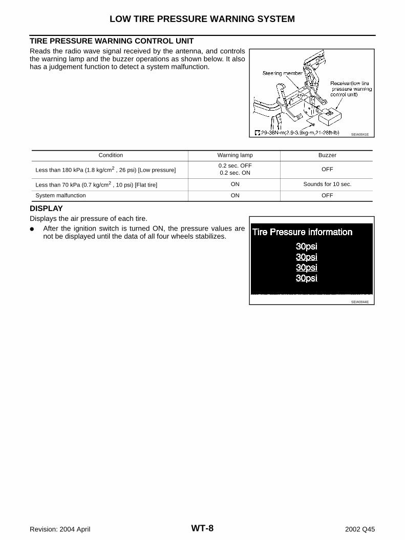
TIRE PRESSURE WARNING CONTROL UNIT Reads the radio wave signal received by the antenna, and controlsthe warning lamp and the buzzer operations as shown below. It alsohas a judgement function to detect a system malfunction.
DISPLAYDisplays the air pressure of each tire.● After the ignition switch is turned ON, the pressure values are
not be displayed until the data of all four wheels stabilizes.
SEIA0041E
Condition Warning lamp Buzzer
Less than 180 kPa (1.8 kg/cm2 , 26 psi) [Low pressure]0.2 sec. OFF0.2 sec. ON
OFF
Less than 70 kPa (0.7 kg/cm2 , 10 psi) [Flat tire] ON Sounds for 10 sec.
System malfunction ON OFF
SEIA0044E
TROUBLE DIAGNOSES
WT-9
C
D
F
G
H
I
J
K
L
M
A
B
WT
Revision: 2004 April 2002 Q45
TROUBLE DIAGNOSES PFP:00004
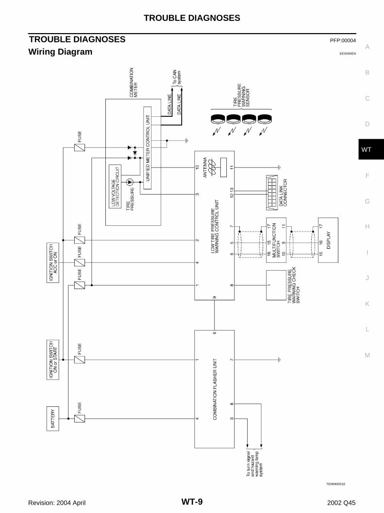
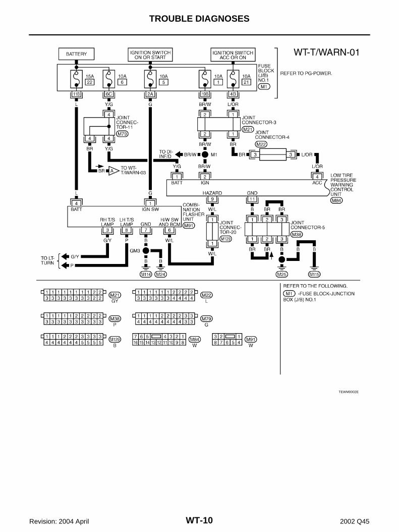
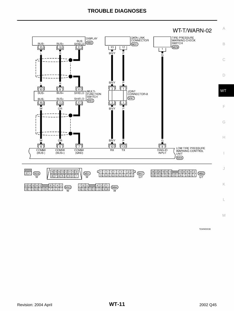
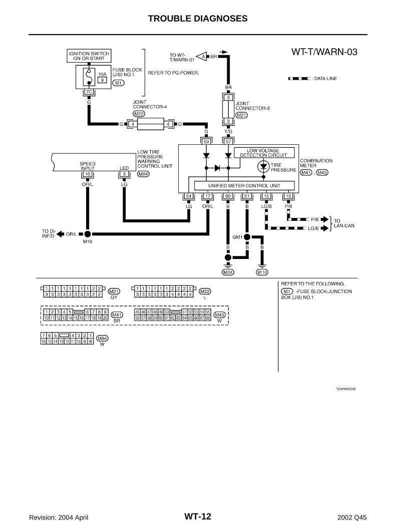
Wiring Diagram EES000EN
TEWM0001E
WT-10
TROUBLE DIAGNOSES
Revision: 2004 April 2002 Q45
TEWM0002E
TROUBLE DIAGNOSES
WT-11
C
D
F
G
H
I
J
K
L
M
A
B
WT
Revision: 2004 April 2002 Q45
TEWM0003E
WT-12
TROUBLE DIAGNOSES
Revision: 2004 April 2002 Q45
TEWM0004E
TROUBLE DIAGNOSES
WT-13
C
D
F
G
H
I
J
K
L
M
A
B
WT
Revision: 2004 April 2002 Q45
ID Registration Procedure EES000EO
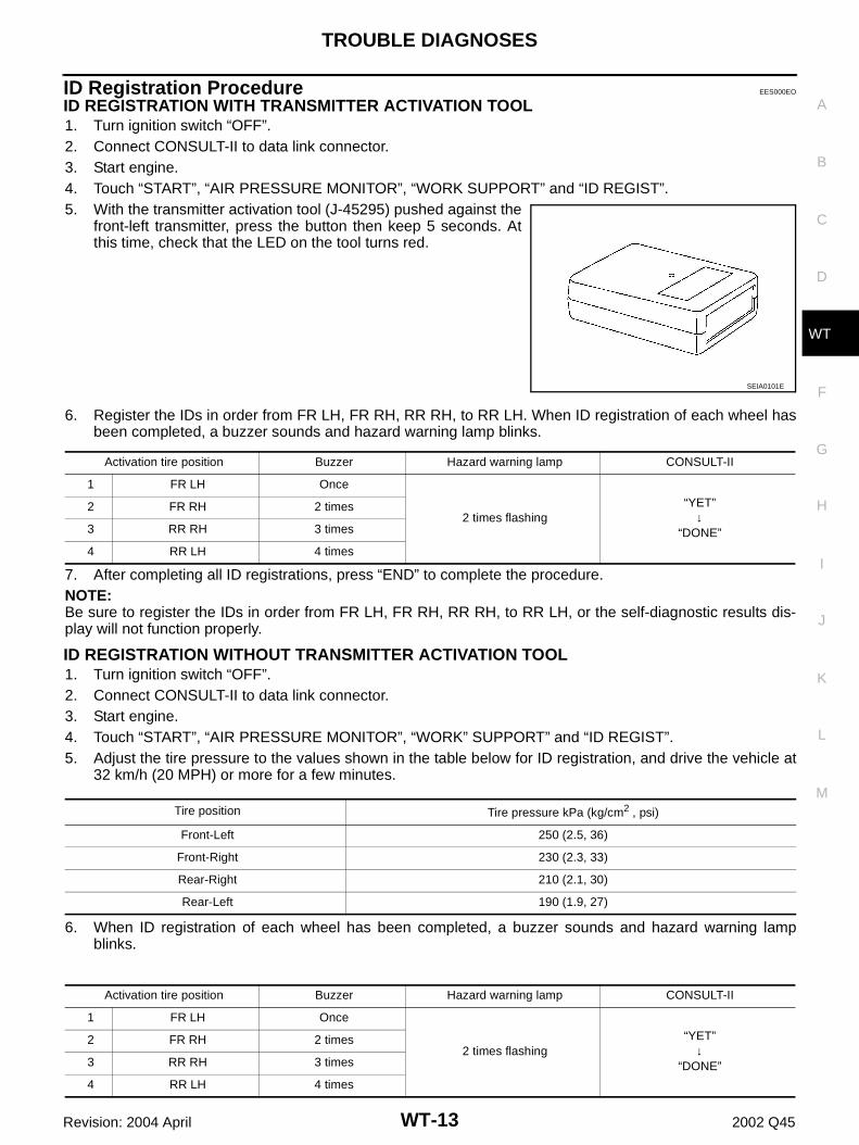
ID REGISTRATION WITH TRANSMITTER ACTIVATION TOOL1. Turn ignition switch “OFF”.2. Connect CONSULT-II to data link connector.3. Start engine.4. Touch “START”, “AIR PRESSURE MONITOR”, “WORK SUPPORT” and “ID REGIST”.5. With the transmitter activation tool (J-45295) pushed against the
front-left transmitter, press the button then keep 5 seconds. Atthis time, check that the LED on the tool turns red.
6. Register the IDs in order from FR LH, FR RH, RR RH, to RR LH. When ID registration of each wheel hasbeen completed, a buzzer sounds and hazard warning lamp blinks.
7. After completing all ID registrations, press “END” to complete the procedure.NOTE:Be sure to register the IDs in order from FR LH, FR RH, RR RH, to RR LH, or the self-diagnostic results dis-play will not function properly.
ID REGISTRATION WITHOUT TRANSMITTER ACTIVATION TOOL1. Turn ignition switch “OFF”.2. Connect CONSULT-II to data link connector.3. Start engine.4. Touch “START”, “AIR PRESSURE MONITOR”, “WORK” SUPPORT” and “ID REGIST”.5. Adjust the tire pressure to the values shown in the table below for ID registration, and drive the vehicle at
32 km/h (20 MPH) or more for a few minutes.
6. When ID registration of each wheel has been completed, a buzzer sounds and hazard warning lampblinks.
SEIA0101E
Activation tire position Buzzer Hazard warning lamp CONSULT-II
1 FR LH Once
2 times flashing“YET”
↓“DONE”
2 FR RH 2 times
3 RR RH 3 times
4 RR LH 4 times
Tire position Tire pressure kPa (kg/cm2 , psi)
Front-Left 250 (2.5, 36)
Front-Right 230 (2.3, 33)
Rear-Right 210 (2.1, 30)
Rear-Left 190 (1.9, 27)
Activation tire position Buzzer Hazard warning lamp CONSULT-II
1 FR LH Once
2 times flashing“YET”
↓“DONE”
2 FR RH 2 times
3 RR RH 3 times
4 RR LH 4 times
WT-14
TROUBLE DIAGNOSES
Revision: 2004 April 2002 Q45
7. After completing all ID registrations, press “END” to complete the procedure.
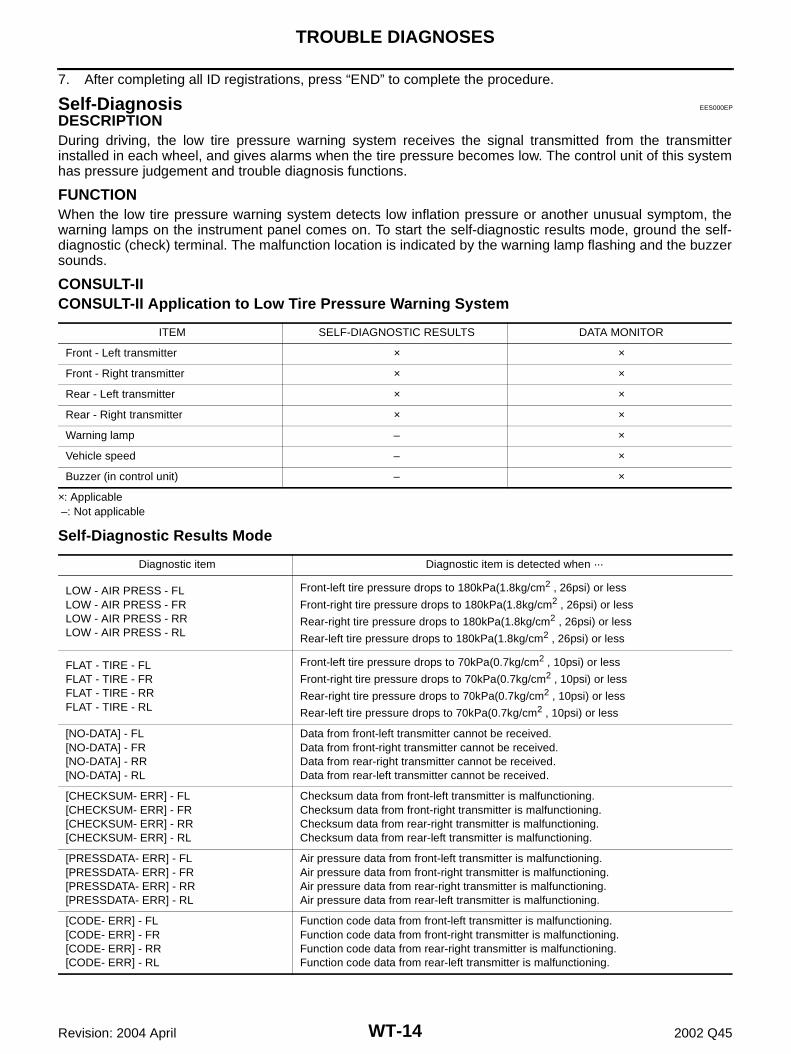
Self-Diagnosis EES000EP
DESCRIPTIONDuring driving, the low tire pressure warning system receives the signal transmitted from the transmitterinstalled in each wheel, and gives alarms when the tire pressure becomes low. The control unit of this systemhas pressure judgement and trouble diagnosis functions.
FUNCTIONWhen the low tire pressure warning system detects low inflation pressure or another unusual symptom, thewarning lamps on the instrument panel comes on. To start the self-diagnostic results mode, ground the self-diagnostic (check) terminal. The malfunction location is indicated by the warning lamp flashing and the buzzersounds.
CONSULT-IICONSULT-II Application to Low Tire Pressure Warning System
×: Applicable –: Not applicable
Self-Diagnostic Results Mode
ITEM SELF-DIAGNOSTIC RESULTS DATA MONITOR
Front - Left transmitter × ×
Front - Right transmitter × ×
Rear - Left transmitter × ×
Rear - Right transmitter × ×
Warning lamp – ×
Vehicle speed – ×
Buzzer (in control unit) – ×
Diagnostic item Diagnostic item is detected when ···
LOW - AIR PRESS - FLLOW - AIR PRESS - FRLOW - AIR PRESS - RRLOW - AIR PRESS - RL
Front-left tire pressure drops to 180kPa(1.8kg/cm2 , 26psi) or less
Front-right tire pressure drops to 180kPa(1.8kg/cm2 , 26psi) or less
Rear-right tire pressure drops to 180kPa(1.8kg/cm2 , 26psi) or less
Rear-left tire pressure drops to 180kPa(1.8kg/cm2 , 26psi) or less
FLAT - TIRE - FLFLAT - TIRE - FRFLAT - TIRE - RRFLAT - TIRE - RL
Front-left tire pressure drops to 70kPa(0.7kg/cm2 , 10psi) or less
Front-right tire pressure drops to 70kPa(0.7kg/cm2 , 10psi) or less
Rear-right tire pressure drops to 70kPa(0.7kg/cm2 , 10psi) or less
Rear-left tire pressure drops to 70kPa(0.7kg/cm2 , 10psi) or less
[NO-DATA] - FL[NO-DATA] - FR[NO-DATA] - RR[NO-DATA] - RL
Data from front-left transmitter cannot be received.Data from front-right transmitter cannot be received.Data from rear-right transmitter cannot be received.Data from rear-left transmitter cannot be received.
[CHECKSUM- ERR] - FL[CHECKSUM- ERR] - FR[CHECKSUM- ERR] - RR[CHECKSUM- ERR] - RL
Checksum data from front-left transmitter is malfunctioning.Checksum data from front-right transmitter is malfunctioning.Checksum data from rear-right transmitter is malfunctioning.Checksum data from rear-left transmitter is malfunctioning.
[PRESSDATA- ERR] - FL[PRESSDATA- ERR] - FR[PRESSDATA- ERR] - RR[PRESSDATA- ERR] - RL
Air pressure data from front-left transmitter is malfunctioning.Air pressure data from front-right transmitter is malfunctioning.Air pressure data from rear-right transmitter is malfunctioning.Air pressure data from rear-left transmitter is malfunctioning.
[CODE- ERR] - FL[CODE- ERR] - FR[CODE- ERR] - RR[CODE- ERR] - RL
Function code data from front-left transmitter is malfunctioning.Function code data from front-right transmitter is malfunctioning.Function code data from rear-right transmitter is malfunctioning.Function code data from rear-left transmitter is malfunctioning.
TROUBLE DIAGNOSES
WT-15
C
D
F
G
H
I
J
K
L
M
A
B
WT
Revision: 2004 April 2002 Q45
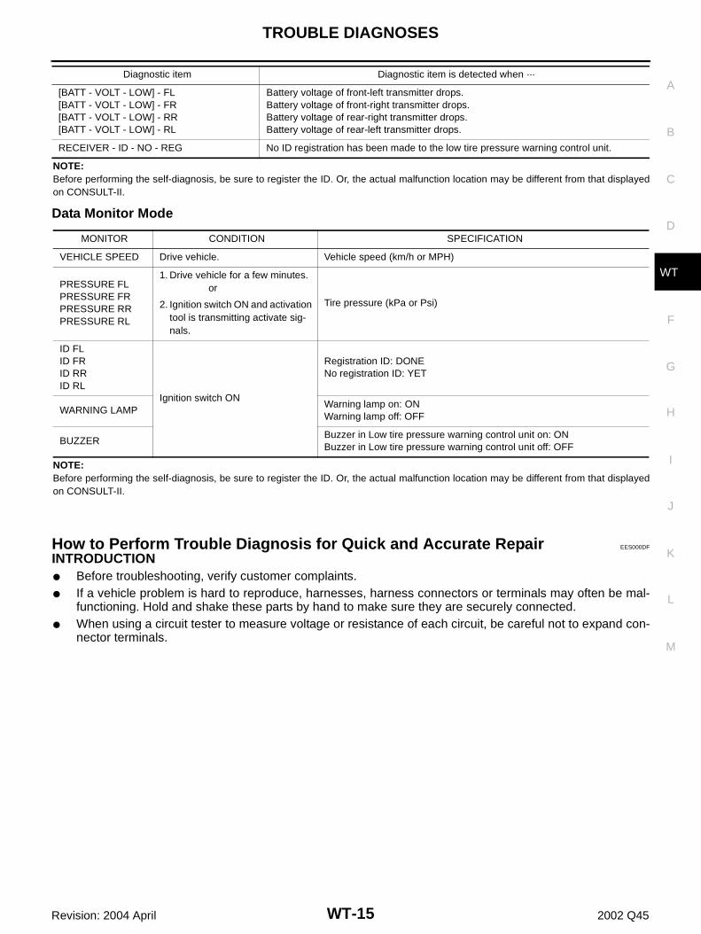
NOTE:Before performing the self-diagnosis, be sure to register the ID. Or, the actual malfunction location may be different from that displayedon CONSULT-II.
Data Monitor Mode
NOTE:Before performing the self-diagnosis, be sure to register the ID. Or, the actual malfunction location may be different from that displayedon CONSULT-II.
How to Perform Trouble Diagnosis for Quick and Accurate Repair EES000DF
INTRODUCTION● Before troubleshooting, verify customer complaints.● If a vehicle problem is hard to reproduce, harnesses, harness connectors or terminals may often be mal-
functioning. Hold and shake these parts by hand to make sure they are securely connected.● When using a circuit tester to measure voltage or resistance of each circuit, be careful not to expand con-
nector terminals.
[BATT - VOLT - LOW] - FL[BATT - VOLT - LOW] - FR[BATT - VOLT - LOW] - RR[BATT - VOLT - LOW] - RL
Battery voltage of front-left transmitter drops.Battery voltage of front-right transmitter drops.Battery voltage of rear-right transmitter drops.Battery voltage of rear-left transmitter drops.
RECEIVER - ID - NO - REG No ID registration has been made to the low tire pressure warning control unit.
Diagnostic item Diagnostic item is detected when ···
MONITOR CONDITION SPECIFICATION
VEHICLE SPEED Drive vehicle. Vehicle speed (km/h or MPH)
PRESSURE FLPRESSURE FRPRESSURE RRPRESSURE RL
1. Drive vehicle for a few minutes. or
2. Ignition switch ON and activation tool is transmitting activate sig-nals.
Tire pressure (kPa or Psi)
ID FLID FRID RRID RL
Ignition switch ON
Registration ID: DONENo registration ID: YET
WARNING LAMPWarning lamp on: ONWarning lamp off: OFF
BUZZERBuzzer in Low tire pressure warning control unit on: ONBuzzer in Low tire pressure warning control unit off: OFF
WT-16
TROUBLE DIAGNOSES
Revision: 2004 April 2002 Q45
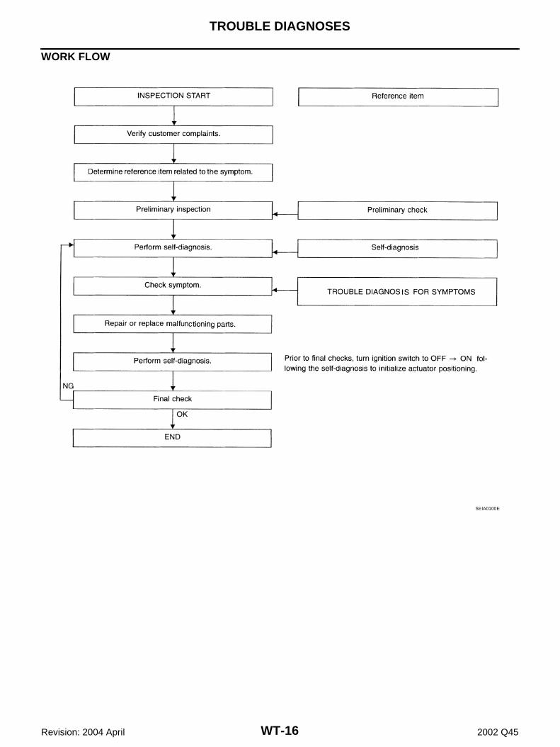
WORK FLOW
SEIA0100E
TROUBLE DIAGNOSES
WT-17
C
D
F
G
H
I
J
K
L
M
A
B
WT
Revision: 2004 April 2002 Q45
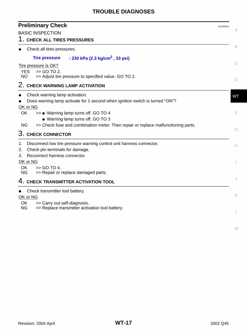
Preliminary Check EES000EQ
BASIC INSPECTION
1. CHECK ALL TIRES PRESSURES
● Check all tires pressures.
Tire pressure is OK?YES >> GO TO 2.NO >> Adjust tire pressure to specified value. GO TO 2.
2. CHECK WARNING LAMP ACTIVATION
● Check warning lamp activation.● Does warning lamp activate for 1 second when ignition switch is turned “ON”?OK or NGOK >> ● Warning lamp turns off. GO TO 4
● Warning lamp turns off. GO TO 3NG >> Check fuse and combination meter. Then repair or replace malfunctioning parts.
3. CHECK CONNECTOR
1. Disconnect low tire pressure warning control unit harness connector.2. Check pin terminals for damage. 3. Reconnect harness connector.OK or NGOK >> GO TO 4.NG >> Repair or replace damaged parts.
4. CHECK TRANSMITTER ACTIVATION TOOL
● Check transmitter tool battery.OK or NGOK >> Carry out self-diagnosis.NG >> Replace transmitter activation tool battery.
Tire pressure : 230 kPa (2.3 kg/cm2 , 33 psi)
WT-18
TROUBLE DIAGNOSES
Revision: 2004 April 2002 Q45
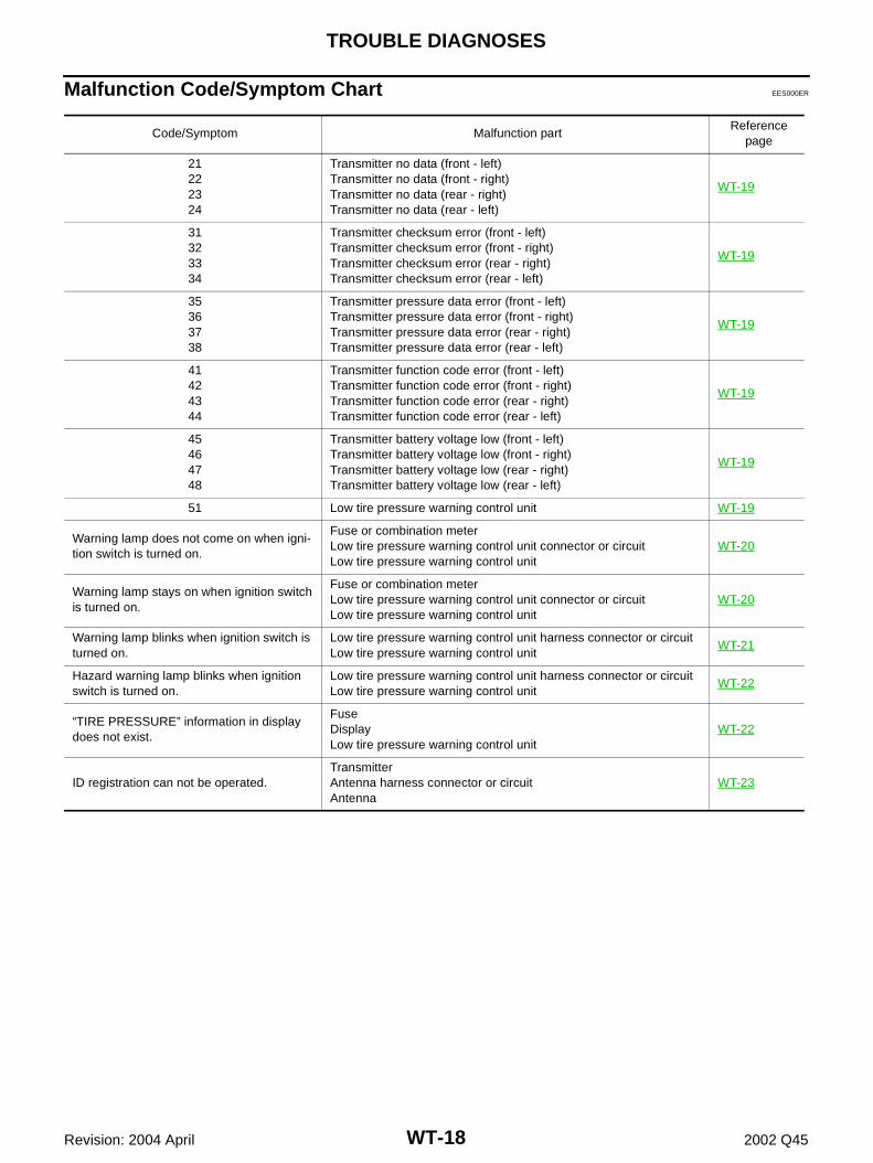
Malfunction Code/Symptom Chart EES000ER
Code/Symptom Malfunction partReference
page
21222324
Transmitter no data (front - left)Transmitter no data (front - right)Transmitter no data (rear - right)Transmitter no data (rear - left)
WT-19
31323334
Transmitter checksum error (front - left)Transmitter checksum error (front - right)Transmitter checksum error (rear - right)Transmitter checksum error (rear - left)
WT-19
35363738
Transmitter pressure data error (front - left)Transmitter pressure data error (front - right)Transmitter pressure data error (rear - right)Transmitter pressure data error (rear - left)
WT-19
41424344
Transmitter function code error (front - left)Transmitter function code error (front - right)Transmitter function code error (rear - right)Transmitter function code error (rear - left)
WT-19
45464748
Transmitter battery voltage low (front - left)Transmitter battery voltage low (front - right)Transmitter battery voltage low (rear - right)Transmitter battery voltage low (rear - left)
WT-19
51 Low tire pressure warning control unit WT-19
Warning lamp does not come on when igni-tion switch is turned on.
Fuse or combination meterLow tire pressure warning control unit connector or circuitLow tire pressure warning control unit
WT-20
Warning lamp stays on when ignition switch is turned on.
Fuse or combination meterLow tire pressure warning control unit connector or circuitLow tire pressure warning control unit
WT-20
Warning lamp blinks when ignition switch is turned on.
Low tire pressure warning control unit harness connector or circuitLow tire pressure warning control unit
WT-21
Hazard warning lamp blinks when ignition switch is turned on.
Low tire pressure warning control unit harness connector or circuitLow tire pressure warning control unit
WT-22
“TIRE PRESSURE” information in display does not exist.
FuseDisplayLow tire pressure warning control unit
WT-22
ID registration can not be operated.TransmitterAntenna harness connector or circuitAntenna
WT-23
TROUBLE DIAGNOSIS FOR SELF-DIAGNOSTIC ITEMS
WT-19
C
D
F
G
H
I
J
K
L
M
A
B
WT
Revision: 2004 April 2002 Q45
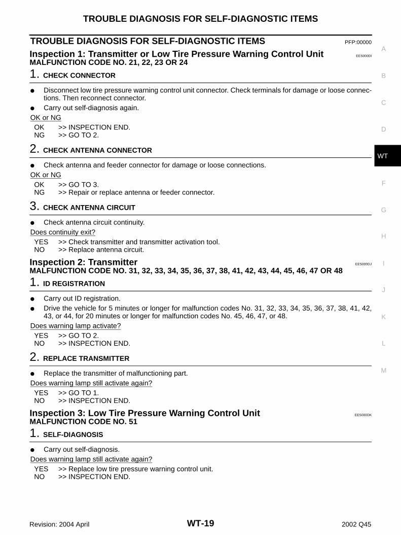
TROUBLE DIAGNOSIS FOR SELF-DIAGNOSTIC ITEMS PFP:00000
Inspection 1: Transmitter or Low Tire Pressure Warning Control Unit EES000DI
MALFUNCTION CODE NO. 21, 22, 23 OR 24
1. CHECK CONNECTOR
● Disconnect low tire pressure warning control unit connector. Check terminals for damage or loose connec-tions. Then reconnect connector.
● Carry out self-diagnosis again.OK or NGOK >> INSPECTION END.NG >> GO TO 2.
2. CHECK ANTENNA CONNECTOR
● Check antenna and feeder connector for damage or loose connections.OK or NGOK >> GO TO 3.NG >> Repair or replace antenna or feeder connector.
3. CHECK ANTENNA CIRCUIT
● Check antenna circuit continuity.Does continuity exit?YES >> Check transmitter and transmitter activation tool.NO >> Replace antenna circuit.
Inspection 2: Transmitter EES000DJ
MALFUNCTION CODE NO. 31, 32, 33, 34, 35, 36, 37, 38, 41, 42, 43, 44, 45, 46, 47 OR 48
1. ID REGISTRATION
● Carry out ID registration.● Drive the vehicle for 5 minutes or longer for malfunction codes No. 31, 32, 33, 34, 35, 36, 37, 38, 41, 42,
43, or 44, for 20 minutes or longer for malfunction codes No. 45, 46, 47, or 48.Does warning lamp activate?YES >> GO TO 2.NO >> INSPECTION END.
2. REPLACE TRANSMITTER
● Replace the transmitter of malfunctioning part.Does warning lamp still activate again?YES >> GO TO 1.NO >> INSPECTION END.
Inspection 3: Low Tire Pressure Warning Control Unit EES000DK
MALFUNCTION CODE NO. 51
1. SELF-DIAGNOSIS
● Carry out self-diagnosis.Does warning lamp still activate again?YES >> Replace low tire pressure warning control unit.NO >> INSPECTION END.
WT-20
TROUBLE DIAGNOSIS FOR SYMPTOMS
Revision: 2004 April 2002 Q45
TROUBLE DIAGNOSIS FOR SYMPTOMS PFP:00007
Inspection 1: Warning Lamp Does Not Come On When Ignition Switch Is Turned On. EES000DL
DIAGNOSTIC PROCEDURE
1. CHECK COMBINATION METER
● Check combination meter operation.OK or NGOK >> GO TO 2.NG >> Check combination meter and repair or replace.
2. CHECK WARNING LAMP
● Disconnect low tire pressure warning control unit connector. Does the warning lamp activate?YES >> Replace combination meter.NO >> GO TO 3.
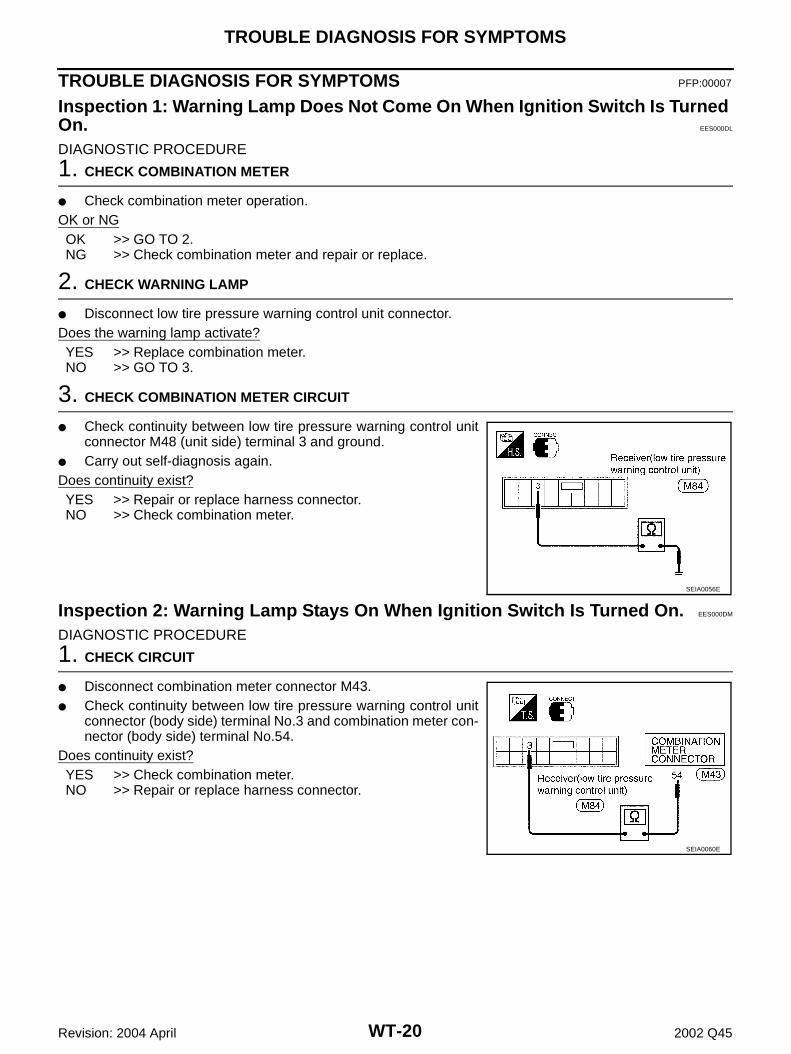
3. CHECK COMBINATION METER CIRCUIT
● Check continuity between low tire pressure warning control unitconnector M48 (unit side) terminal 3 and ground.
● Carry out self-diagnosis again.Does continuity exist?YES >> Repair or replace harness connector.NO >> Check combination meter.
Inspection 2: Warning Lamp Stays On When Ignition Switch Is Turned On. EES000DM
DIAGNOSTIC PROCEDURE
1. CHECK CIRCUIT
● Disconnect combination meter connector M43.● Check continuity between low tire pressure warning control unit
connector (body side) terminal No.3 and combination meter con-nector (body side) terminal No.54.
Does continuity exist?YES >> Check combination meter.NO >> Repair or replace harness connector.
SEIA0056E
SEIA0060E
TROUBLE DIAGNOSIS FOR SYMPTOMS
WT-21
C
D
F
G
H
I
J
K
L
M
A
B
WT
Revision: 2004 April 2002 Q45
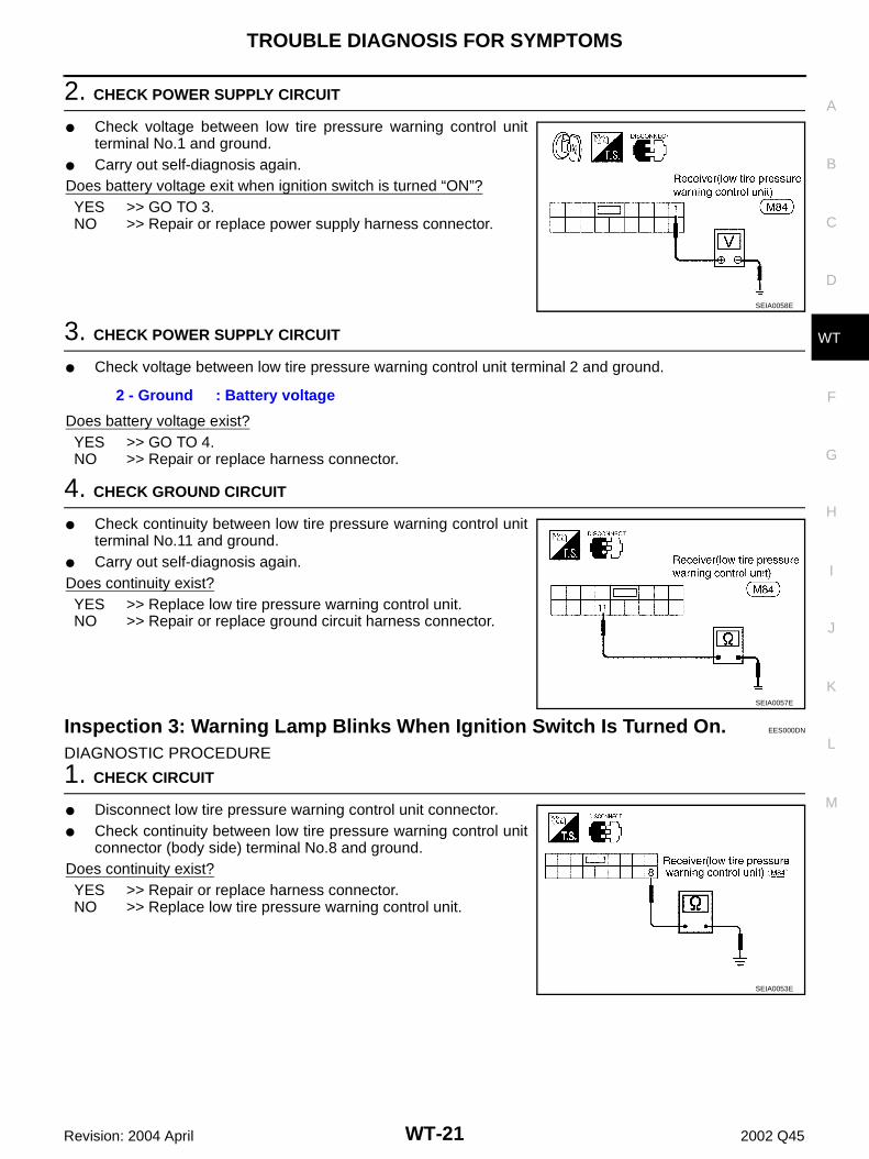
2. CHECK POWER SUPPLY CIRCUIT
● Check voltage between low tire pressure warning control unitterminal No.1 and ground.
● Carry out self-diagnosis again.Does battery voltage exit when ignition switch is turned “ON”?YES >> GO TO 3.NO >> Repair or replace power supply harness connector.
3. CHECK POWER SUPPLY CIRCUIT
● Check voltage between low tire pressure warning control unit terminal 2 and ground.
Does battery voltage exist?YES >> GO TO 4.NO >> Repair or replace harness connector.
4. CHECK GROUND CIRCUIT
● Check continuity between low tire pressure warning control unitterminal No.11 and ground.
● Carry out self-diagnosis again.Does continuity exist?YES >> Replace low tire pressure warning control unit.NO >> Repair or replace ground circuit harness connector.
Inspection 3: Warning Lamp Blinks When Ignition Switch Is Turned On. EES000DN
DIAGNOSTIC PROCEDURE
1. CHECK CIRCUIT
● Disconnect low tire pressure warning control unit connector.● Check continuity between low tire pressure warning control unit
connector (body side) terminal No.8 and ground.Does continuity exist?YES >> Repair or replace harness connector.NO >> Replace low tire pressure warning control unit.
SEIA0058E
2 - Ground : Battery voltage
SEIA0057E
SEIA0053E
WT-22
TROUBLE DIAGNOSIS FOR SYMPTOMS
Revision: 2004 April 2002 Q45
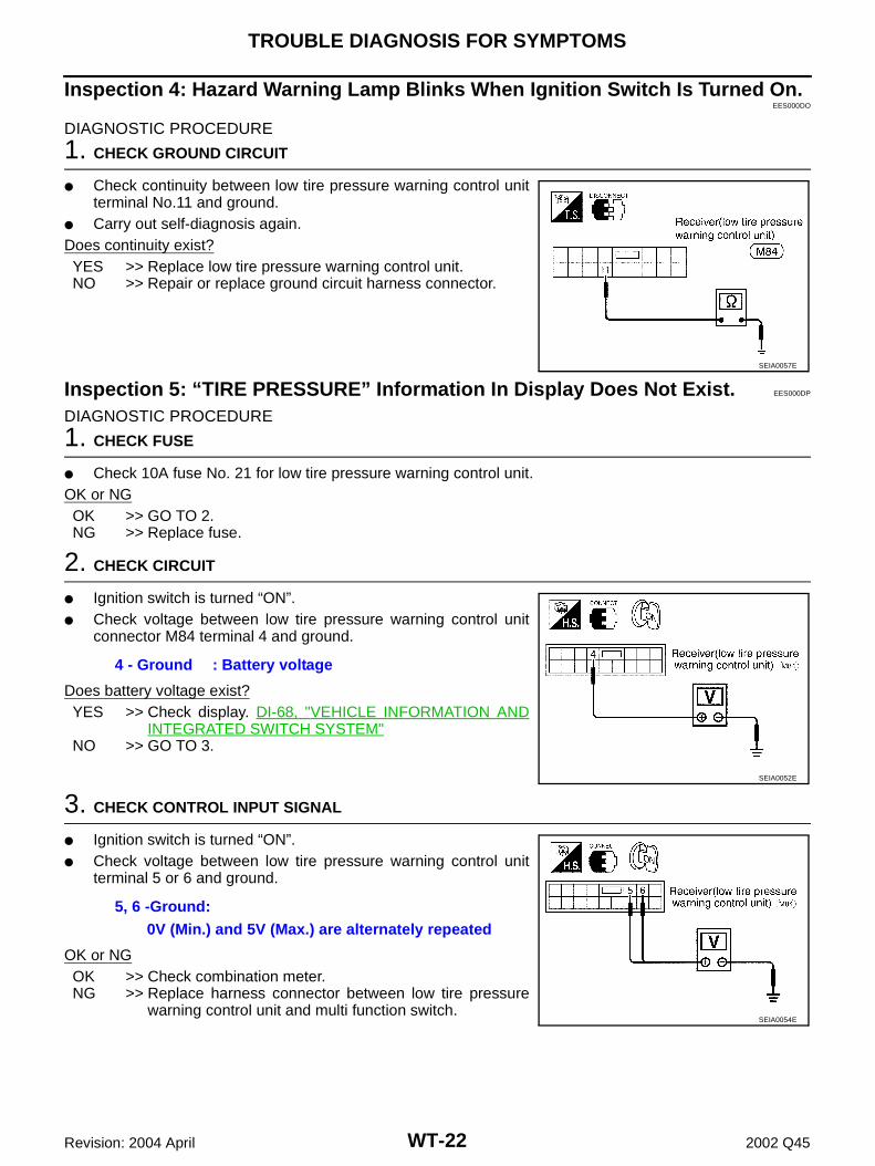
Inspection 4: Hazard Warning Lamp Blinks When Ignition Switch Is Turned On.EES000DO
DIAGNOSTIC PROCEDURE
1. CHECK GROUND CIRCUIT
● Check continuity between low tire pressure warning control unitterminal No.11 and ground.
● Carry out self-diagnosis again.Does continuity exist?YES >> Replace low tire pressure warning control unit.NO >> Repair or replace ground circuit harness connector.
Inspection 5: “TIRE PRESSURE” Information In Display Does Not Exist. EES000DP
DIAGNOSTIC PROCEDURE
1. CHECK FUSE
● Check 10A fuse No. 21 for low tire pressure warning control unit.OK or NGOK >> GO TO 2.NG >> Replace fuse.
2. CHECK CIRCUIT
● Ignition switch is turned “ON”.● Check voltage between low tire pressure warning control unit
connector M84 terminal 4 and ground.
Does battery voltage exist?YES >> Check display. DI-68, "VEHICLE INFORMATION AND
INTEGRATED SWITCH SYSTEM"NO >> GO TO 3.
3. CHECK CONTROL INPUT SIGNAL
● Ignition switch is turned “ON”.● Check voltage between low tire pressure warning control unit
terminal 5 or 6 and ground.
OK or NGOK >> Check combination meter. NG >> Replace harness connector between low tire pressure
warning control unit and multi function switch.
SEIA0057E
4 - Ground : Battery voltage
SEIA0052E
5, 6 -Ground:0V (Min.) and 5V (Max.) are alternately repeated
SEIA0054E
TROUBLE DIAGNOSIS FOR SYMPTOMS
WT-23
C
D
F
G
H
I
J
K
L
M
A
B
WT
Revision: 2004 April 2002 Q45
Inspection 6: ID Registration Can Not Be Completed EES000DQ
DIAGNOSTIC PROCEDURE
1. ID REGISTRATION (ALL)
● Carry out ID registration of all transmitter.● Can ID registration of all transmitter be completed?YES or NO?YES >> INSPECTION END.NO >> Go To Inspection 1: Transmitter or Low Tire Pressure Warning Control Unit.
WT-24
REMOVAL AND INSTALLATION
Revision: 2004 April 2002 Q45
REMOVAL AND INSTALLATION PFP:00000
Transmitter EES000DS
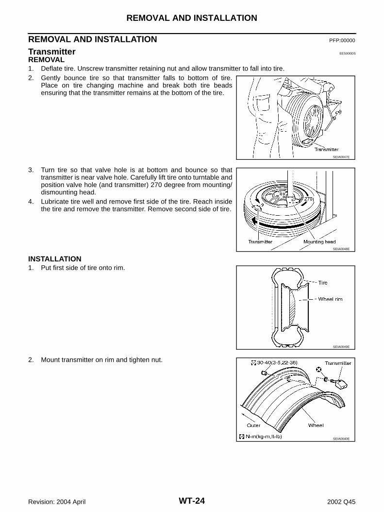
REMOVAL1. Deflate tire. Unscrew transmitter retaining nut and allow transmitter to fall into tire.2. Gently bounce tire so that transmitter falls to bottom of tire.
Place on tire changing machine and break both tire beadsensuring that the transmitter remains at the bottom of the tire.
3. Turn tire so that valve hole is at bottom and bounce so thattransmitter is near valve hole. Carefully lift tire onto turntable andposition valve hole (and transmitter) 270 degree from mounting/dismounting head.
4. Lubricate tire well and remove first side of the tire. Reach insidethe tire and remove the transmitter. Remove second side of tire.
INSTALLATION1. Put first side of tire onto rim.
2. Mount transmitter on rim and tighten nut.
SEIA0047E
SEIA0048E
SEIA0049E
SEIA0040E
REMOVAL AND INSTALLATION
WT-25
C
D
F
G
H
I
J
K
L
M
A
B
WT
Revision: 2004 April 2002 Q45
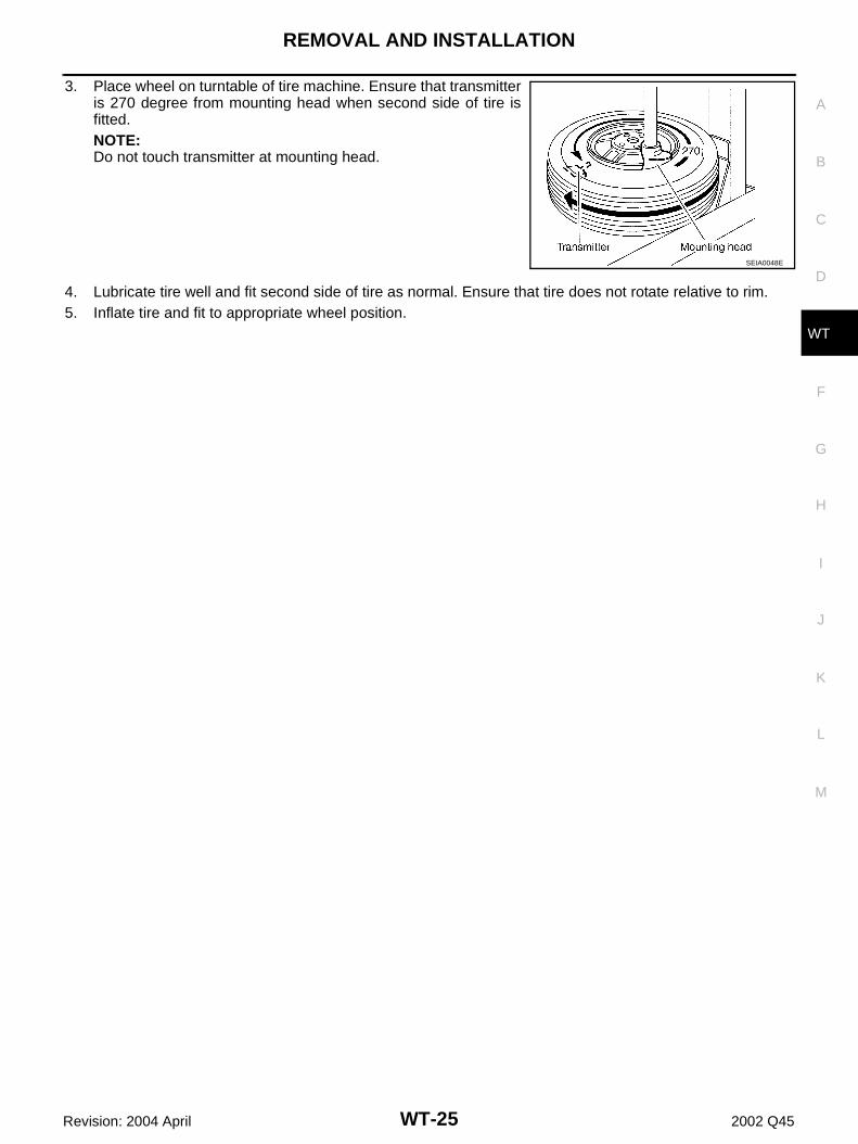
3. Place wheel on turntable of tire machine. Ensure that transmitteris 270 degree from mounting head when second side of tire isfitted. NOTE:Do not touch transmitter at mounting head.
4. Lubricate tire well and fit second side of tire as normal. Ensure that tire does not rotate relative to rim.5. Inflate tire and fit to appropriate wheel position.
SEIA0048E
WT-26
SERVICE DATA
Revision: 2004 April 2002 Q45
SERVICE DATA PFP:00030
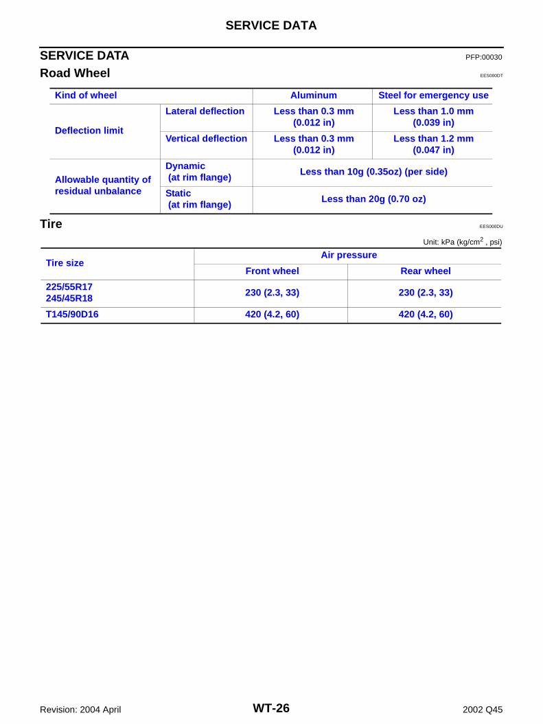
Road Wheel EES000DT
Tire EES000DU
Unit: kPa (kg/cm2 , psi)
Kind of wheel Aluminum Steel for emergency use
Deflection limit
Lateral deflection Less than 0.3 mm(0.012 in)
Less than 1.0 mm(0.039 in)
Vertical deflection Less than 0.3 mm(0.012 in)
Less than 1.2 mm(0.047 in)
Allowable quantity of residual unbalance
Dynamic (at rim flange)
Less than 10g (0.35oz) (per side)
Static (at rim flange)
Less than 20g (0.70 oz)
Tire sizeAir pressure
Front wheel Rear wheel
225/55R17245/45R18
230 (2.3, 33) 230 (2.3, 33)
T145/90D16 420 (4.2, 60) 420 (4.2, 60)


![AUTO CRUISE CONTROL SYSTEM K ELECTRICAL …pdf.textfiles.com/manuals/AUTOMOBILE/NISSAN/Q45/2006_Q45/...ACS-6 [ICC] DESCRIPTION Revision: 2005 November 2006 Q45 DESCRIPTION PFP:00000](https://img.pdfslide.net/doc/110x75/5ae4d79e7f8b9a0d7d8f7e64/auto-cruise-control-system-k-electrical-pdf-icc-description-revision-2005.jpg)