Embed Size (px)
Citation preview
TM 11-5820-498-35 DEPARTMENT OF THE ARMY TECHNICAL MANUAL
DS,GS, AND DEPOT
MAINTENANCE MANUAL
RADIO SETSAN/VRC-53, AN/VRC-64, AN/GRC-125
AND AN/GRC-160AND
AMPLIFIER-POWER SUPPLY GROUPSOA-3633/GRC AND OA-3633A/GRC
This copy is a reprint which includes current
pages from Changes 1 through 4.
HEADQUARTERS, DEPARTMENT OF THE ARMY
DECEMBER 1969

Change
No. 4
TM 11-5820-498-35C 4
HEADQUARTERSDEPARTMENT OF THE ARMY
WASHINGTON, DC, 12 October 1981
Direct Support, General Support, andDepot Maintenance Manual
RADIO SETS AN/VRC-53 (NSN 5820-00-223-7467),AN/VRC-64 (NSN 5820-00-223-7475),
AN/GRC-125 (NSN 5820-00-223-7411) ANDAN/GRC-160 (NSN 5820-00-223-7473) AND
AMPLIFIER-POWER SUPPLY GROUPSOA-3633/GRC AND OA-3633A/GRC
(NSN 5820-00-973-3383)
TM 11-5820-498-35, 22 December 1969, is changed as follows:1. New or changed material is indicated by a bar in the margin.2. Remove and insert pages as indicated below.
Remove InsertNone. . . . . . . . . . . . . . . . . . . . . . . . . . . . . . . . . . . . . . . . . . . . . . . . . . . . . . . . . . . . . . . . . . . . . . . . . A/(B blsnk)1-1 and 1-2. . . . . . . . . . . . . . . . . . . . . . . . . . . . . . . . . . . . . . . . . . . . . . . . . . . . . . . . . . . . 1-1 and 1-24-1 . . . . . . . . . . . . . . . . . . . . . . . . . . . . . . . . . . . . . . . . . . . . . . . . . . . . . . . . . . . . . . . . . . . . ..4-1A-1 and A-2. . . . . . . . . . . . . . . . . . . . . . . . . . . . . . . . . . . . . . . . . . . . . . . . . . . . . . . . . . . . . . . . . . . A-1 through A-2
3. File this change sheet in front of the manual for reference purposes.
DISTRIBUTION:To be distributed in accordance with DA Form 12-51, Direct and General Support Maintenance requirements
for AN/VRC-53, 64, AN/GRC-125, 160.

CHANGE
No. 3
TM 11-5820-498-35C 3
HEADQUARTERSDEPARTMENT OF THE ARMYWASHINGTON, DC, 28 April 1981
Direct Support, General Support, AndDepot Maintenance Manual
RADIO SETS AN/VRC-53 (NSN 5820-00-223-7467),AN/VRC-64 (NSN 5820-00-223-7475),
AN/GRC-125 (NSN 5820-00-223-7411), ANDAN/GRC-160 (NSN 5820-00-223-7473), AND
AMPLIFIER-POWER SUPPLY GROUPSOA-3633/GRC AND OA-3633A/GRC
(NSN 5820-00-973-3383)
TM 11-5820-498-35, 22 December 1969, is changed as follows:1. Title of the manual is changed as indicated above.2. This change covers OA-363A/GRC, procured on Contract DAAB07-79-C-0068 (para 1-4a(1)).3. New or changed material is indicated by a bar in the margin.4. Remove and insert pages as indicated below:
Remove po.ges Insert pages1-1 and 1-2. . . . . . . . . . . . . . . . . . . . . . . . . . . . . . . . . . . . . . . . . . . . . . . . . . . . . . . . 1-1 and 1-23-17 and 3-18 . . . . . . . . . . . . . . . . . . . . . . . . . . . . . . . . . . . . . . . . . . . . . . . . . . . . . 3-17 through 3-18.1Figure 4-9 . . . . . . . . . . . . . . . . . . . . . . . . . . . . . . . . . . . . . . . . . . . . . . . . . . . . . . . . Figure 4-9
5. File this change sheet in the front of the manual for reference purposes.
By Order of the Secretary of the Army:
E. C. MEYERGeneral, United States Army
Official: Chief of Staff
J. C. PENNINGTONMajor General, United States Army
The Adjutant General
DISTRIBUTION:To be distributed in accordance with DA Form 12-51 Direct and General Support maintenance
requirements for AN/VRC-53, AN/VRC-64, AN/GRG-125, AN/GRC-160.

W A R N I N G
Remove the battery from the radio sets when the radio sets are not being used. This iS
required to prevent Hydrogen gas (a by-product of Magnesium Battery, BA-4386/Udischarge action) from accumulating. Personnel may be injured and equipment damagedif the gas explodes.You can tell the difference between Magnesium Battery, BA-4386/U, and LithiumBattery, BA-5598/U, by looking at their size. The lithium battery is half the size of(smaller than) the magnesium battery. Both the magnesium and lithium batteries aredisposed of in a sanitary landfill.
W A R N I N G
A lithium battery is used in this equipment, and is potentially hazardous if misusedor tampered with before, during, and after discharge. The following precautionsmust be strictly observed to prevent possible injury to personnel or damage toequipment.DO NOT heat, incinerate, crush, puncture, disassemble, or otherwise mutilate thebatteries.DO NOT short circuit.DO NOT recharge.DO NOT bypass internal fuse or replace with a fuse of a different rating. Replace-ment fuses are packed two per every ten batteries.DO NOT store in equipment during long periods of unuse in excess of 30 days.TURN OFF the equipment immediately if you detect the battery compartmentbecoming unduly hot or rapidly increasing in temperature, hear battery venting(hissing sound), or smell irritating sulfur dioxide gas. Remove and dispose of thebattery only after it is cool (30-60 minutes).DO NOT use carbon dioxide extinguishers on exposed lithium fuel fires. Flood theburning material with water or use graphite type compounds or extinguishers toextinguish burning lithium.
Change 4 A/(B blank)


TECHNICAL MANUAL
o. 11-5820-498-35)
HEADQUARTERSDEPARTMENT OF THE ARMY
WASHINGTON , D. C., 22 December 1969
DS, GS, and Depot Maintenance Manual
RADIO SETS AN/VRC-53 , AN/VRC-64 , AN/GRC-125
AND AN/GRC-160, AND AMPLIFIER-POWER SUPPLY GROUPS
O A - 3 6 3 3 / G R C A N D O A - 3 6 3 3 A / G R C
ParapgraphsCHAPTER 1. INTRODUCTION . . . . . . . . . . . . . . . . . . . . . . . . . . . . . . . . . . . . . . . . . . . . 1-1—1-4
2. CIRCUIT FUNCTIONINGSection I. Radio, and radio with intercom, circuit functioning . . . . . . . . . . . . . . . . . . . .2-1—2-5
II. Retransmission circuit functioning . . . . . . . . . . . . . . . . . . . . . . . . . . .2-6—2-8III. Amplifier-Power Supply Group OA-3633(*)/GRC, circuit functioning . . . . . . . . . .2-9—2-11
CHAPTER 3. DS AND GS MAINTENANCE, AMPLIFIER-POWER SUPPLY GROUPOA-3633(*)/GRC.
Section I. General troubleshooting techniques. . . . . . . . . . . . . . . . . . . . . . . . . . . . 3-1—3-4II. OA-3633(*)/GRC; troubleshooting procedure . . . . . . . . . . . . . . . . . . . . . . . . . . . .3-5—3-11
III. OA-3633(*)/GRC, parts removal and replacement procedures . . . . . . . . . . . . . . . . . .3-12—3-16IV. OA-3633(*)GRC, testing procedures . . . . . . . . . . . . . . . . . . . . . . . . . . . 3-17—3-24
CHAPTER 4. DEPOT OVERHAUL STANDARDS . . . . . . . . . . . . . . . . . . . . . . . . . . . . . . . . . . . . . . . . . . . . .4-1—4-4APPENDIX A. REFERENCES . . . . . . . . . . . . . . . . . . . . . . . . . . . . . . . . . . . . . . . . . . . . . . . . . . . . .
Page1-1
2-12-8
2-11
3-23-5
3-133-184-1A-1
* TM 11-5820-498-35
i
* T h i s m a n u a l s u p e r s e d e s T M 1 1 - 5 8 2 0 - 4 9 8 - 3 5 , 7 F e b r u a r y 1 9 6 3 , i n c l u d i n g a l l c h a n g e s .

CHAPTER 1INTRODUCTION
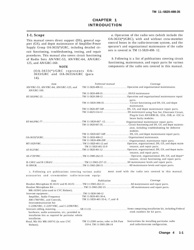
1-1. Scope a. Operation of the radio sets (which include the
This manual covers direct support (DS), general sup- OA-3633(*)/GRC), with and without crew-member
port (GS), and depot maintenance of Amplifier-Power control boxes in the radio-intercom system, and the
Supply Group OA-3633(*)/GRC, including detailed cir- operator’s and organizational maintenance of the radio
cuit functioning, troubleshooting, testing, and repair sets is covered in TM 11-5820-498- 12.
procedures. This manual also covers circuit functioningof Radio Sets AN/VRC-53, AN/VRC-64, AN/GRC- b. Following is a list of publications covering circuit125, and AN/GRC-160. functioning, maintenance, and repair parts for various
NOTE components of the radio sets covered in this manual.(OA-3633(*)/GRC represents OA-3633/GRC and OA-3633A/GRC (para14).
Item Technical manual CoverageAN/VRC-53, AN/VRC-64, AN/GRC-125, and TM 11-5820-498-12. . . . . . . . . . . . . . . . . . . Operation and organizational maintenance.
AN/GRC-160.TM 11-5820-498-35 . . . . . . . . . . . . . . . . . . . DS/GS maintenance
RT-505/PRC-25 . . . . . . . . . . . . . . . . . . . . . . . . . . . . . . . TM 11-5820-398-12 . . . . . . . . . . . . . . . . . . . Operation and organizational maintenance repairparts.
TM 11-5820-398-35 . . . . . . . . . . . . . . . . . . . Circuit functioning and DS, GS, and depotmaintenance.
TM 11-5820-497-34P. . . . . . . . . . . . . . . . . . DS, GS, and depot maintenance repair parts.TM 11-6625-514-12 . . . . . . . . . . . . . . . . . . . DS maintenance using Test Set, Electronic Circuit,
Plug-In Unit AN/GRM-56, -55A, -55B, or -55C tolocate faulty modules.
RT-841/PRC-77 . . . . . . . . . . . . . . . . . . . . . . . . . . . . . . . TM 11-5820-667 -12. . . . . . . Organizational maintenance repair parts.TM 11-5820-667-35. . . . . . . . . . . . . . . . . . . Circuit functioning and DS, GS, and depot mainten-
ance, including troubleshooting for defectivemodules.
TM 11-5820-667-34P. . . . . . . . . . . . . . . . . . DS, GS, and depot maintenance repair parts.OA-3633(*)/GRC. . . . . . . . . . . . . . . . . . . . . . . . . . . . . . TM 11-5820-498-12 . . . . . . . . . . . . . . . . . . . Organizational maintenance.
TM 11-5820-498-20P. . . . . . . . . . . . . . . . . .Organizational, maintenance repair parts.MT-1029/VRC . . . . . . . . . . . . . . . . . . . . . . . . . . . . . . . . TM 11-5820-401-12 and Operator, organizational, DS, GS, and depot maim
TM 11-5820-401-35-9 tenance, and repair parts.AT-912/VRC . . . . . . . . . . . . . . . . . . . . . . . . . . . . . . . . . TM 11-5820-401-12 . . . . . . . . . . . . . . . . . . . Operator, organizational, DS, GS, and depot main-
tenance, and repair parts.AS-1729/VRC . . . . . . . . . . . . . . . . . . . . . . . . . . . . . . . . TM 11-5985-262-15 . . . . . . . . . . . . . . . . . . . Operator, organizational, DS, GS, and depot*
tenance, circuit functioning, and repair parts.H-138/U and H-138A/U . . . . . . . . . . . . . . . . . . . . . . . TM 11-5965-257-15 . . . . .. . . . . . . . . . . . . All maintenance levels and repair parts.H-189/GR. . . . . . . . . . . . . . . . . . . . . . . . . . . . . . . . . . . . TM 11-5965-280-15 . . . . . . . . . . . . . . . . . . . All maintenance levels and repair parts.
c. Following are publications covering various audio ment used with the radio sets covered in this manual.
accessories and crewmember radio-intercom equip-
Item Publication CoverageHeadset-Microphone H-161/U and H-161/U. . . . . . TM 11-5965-262-13 . . . . . . . . . . . . . . . . . . . All maintenance and repair parts.Headset Microphone Kit . . . . . . . . . . . . . . . . . . . . . . TM 11-5965-282-15. . . . . . . . . . . . . . . . . . . All maintenance and repair parts.
MK-1039/G (also used in CVC Helmet).Intercom equipment:. . . . . . . . . . . . . . . . . . . . . . . . . . TM 11-5830-340-12
Amplifier, Audio Frequency TM 11-5820-401-30-4,AM-1780/VRC, and Controls, TM 11-5820-401-35-6, -7, and -8Intercommunication SetC-2296/VRC, C-2297/VRC, and C-2298/VRC.
Interunit cabling, mounting. . . . . . . . . . . . . . . . . . . SB 11-131 . . . . . . . . . . . . . . . . . . . . . . . . . . . Items comprising installation kit, including Federalhardware, audio accessories, etc.; provided in stock numbers for kit parts.installation kits as required for particular vehicleinstallation.
Head, Mic Kit MK-1697/G (in new CVC TM 11-2300 series; refer to DA Pam Instructions for installing particular radioHelmet). 310-4. TM 11-5965-286-14 and radio-Intercom configuration.
Change 4 1-1
TM 11--5820-498-35
TM 11-5820-498-35
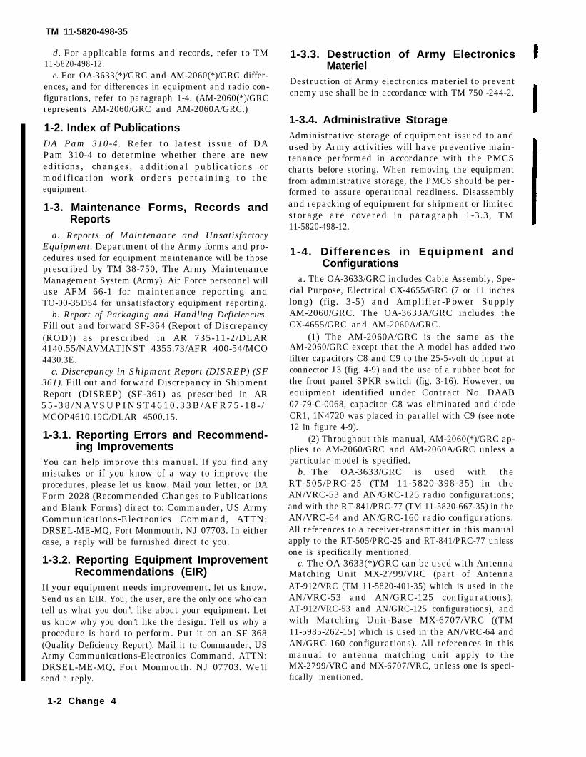
d. For applicable forms and records, refer to TM11-5820-498-12.
e. For OA-3633(*)/GRC and AM-2060(*)/GRC differ-ences, and for differences in equipment and radio con-figurations, refer to paragraph 1-4. (AM-2060(*)/GRCrepresents AM-2060/GRC and AM-2060A/GRC.)
1-2. Index of PublicationsDA Pam 310-4. Refer to latest issue of DAPam 310-4 to determine whether there are neweditions, changes, additional publications ormodification work orders pertaining to theequipment.
1-3. Maintenance Forms, Records andReports
a. Reports of Maintenance and UnsatisfactoryEquipment. Department of the Army forms and pro-cedures used for equipment maintenance will be thoseprescribed by TM 38-750, The Army MaintenanceManagement System (Army). Air Force personnel willuse AFM 66-1 for maintenance reporting andTO-00-35D54 for unsatisfactory equipment reporting.
b. Report of Packaging and Handling Deficiencies.Fill out and forward SF-364 (Report of Discrepancy(ROD)) as prescribed in AR 735-11-2/DLAR4140.55/NAVMATINST 4355.73/AFR 400-54/MCO4430.3E.
c. Discrepancy in Shipment Report (DISREP) (SF361). Fill out and forward Discrepancy in ShipmentReport (DISREP) (SF-361) as prescribed in AR55-38 /NAVSUPINST4610.33B/AFR75-18- /MCOP4610.19C/DLAR 4500.15.
1-3.1. Reporting Errors and Recommend-ing Improvements
You can help improve this manual. If you find anymistakes or if you know of a way to improve theprocedures, please let us know. Mail your letter, or DAForm 2028 (Recommended Changes to Publicationsand Blank Forms) direct to: Commander, US ArmyCommunications-Electronics Command, ATTN:DRSEL-ME-MQ, Fort Monmouth, NJ 07703. In eithercase, a reply will be furnished direct to you.
1-3.2. Reporting Equipment ImprovementRecommendations (EIR)
If your equipment needs improvement, let us know.Send us an EIR. You, the user, are the only one who cantell us what you don’t like about your equipment. Letus know why you don’t like the design. Tell us why aprocedure is hard to perform. Put it on an SF-368(Quality Deficiency Report). Mail it to Commander, USArmy Communications-Electronics Command, ATTN:DRSEL-ME-MQ, Fort Monmouth, NJ 07703. We’llsend a reply.
1-2 Change 4
1-3.3. Destruction of Army ElectronicsMateriel
Destruction of Army electronics materiel to preventenemy use shall be in accordance with TM 750 -244-2.
1-3.4. Administrative StorageAdministrative storage of equipment issued to andused by Army activities will have preventive main-tenance performed in accordance with the PMCScharts before storing. When removing the equipmentfrom administrative storage, the PMCS should be per-formed to assure operational readiness. Disassemblyand repacking of equipment for shipment or limitedstorage are covered in paragraph 1-3.3, TM11-5820-498-12.
1-4. Differences in Equipment andConfigurations
a. The OA-3633/GRC includes Cable Assembly, Spe-cial Purpose, Electrical CX-4655/GRC (7 or 11 incheslong) (fig. 3-5) and Amplifier-Power SupplyAM-2060/GRC. The OA-3633A/GRC includes theCX-4655/GRC and AM-2060A/GRC.
(1) The AM-2060A/GRC is the same as theAM-2060/GRC except that the A model has added twofilter capacitors C8 and C9 to the 25-5-volt dc input atconnector J3 (fig. 4-9) and the use of a rubber boot forthe front panel SPKR switch (fig. 3-16). However, onequipment identified under Contract No. DAAB07-79-C-0068, capacitor C8 was eliminated and diodeCR1, 1N4720 was placed in parallel with C9 (see note12 in figure 4-9).
(2) Throughout this manual, AM-2060(*)/GRC ap-plies to AM-2060/GRC and AM-2060A/GRC unless aparticular model is specified.
b. The OA-3633/GRC is used with theRT-505/PRC-25 (TM 11-5820-398-35) in theAN/VRC-53 and AN/GRC-125 radio configurations;and with the RT-841/PRC-77 (TM 11-5820-667-35) in theAN/VRC-64 and AN/GRC-160 radio configurations.All references to a receiver-transmitter in this manualapply to the RT-505/PRC-25 and RT-841/PRC-77 unlessone is specifically mentioned.
c. The OA-3633(*)/GRC can be used with AntennaMatching Unit MX-2799/VRC (part of AntennaAT-912/VRC (TM 11-5820-401-35) which is used in theAN/VRC-53 and AN/GRC-125 configurations),AT-912/VRC-53 and AN/GRC-125 configurations), andwith Matching Unit-Base MX-6707/VRC ((TM11-5985-262-15) which is used in the AN/VRC-64 andAN/GRC-160 configurations). All references in thismanual to antenna matching unit apply to theMX-2799/VRC and MX-6707/VRC, unless one is speci-fically mentioned.

CHAPTER 2
CIRCUIT FUNCTIONING
Section I. RADIO, AND RADIO WITH INTERCOM,CIRCUIT FUNCTIONING
2-1. Generala. The radio sets include a receiver-transmitter
(RT-505/PRC-25 or RT-841/PRC-77), a whipantenna (AT-912/VRC or AS-1729/VRC), theMT-1029/VRC, and OA-3633(*)/GRC. An audioaccessory, interconnecting cables, and mountinghardware to mount the radio sets in a vehicle areprovided in the installation unit (kit) applicableto the radio set installation (SB 11-131).
b. The OA-3633(*)/GRC converts the nominal24-volt vehicular battery to operating voltages(13, 2.6, and 3 volts dc) for itself and the re-ceiver-transmitter. It also has provision for lis-tening on a loudspeaker to the signals received onthe receiver-transmitter, and for matching theoutput of the receiver-transmitter to the whip an-tenna matching network.
c. The radio sets are also capable of operatingwith a vehicular radio-intercommunication (inter-com system. The intercom system includes a cen-tral audio and power control (Amplifier, AudioFrequency AM-1780/VRC), and crewmembercontrol boxes (Controls, Intercommunication SetC-2296/VRC (located on the rear outside the ve-hicle), C-2297/VRC (for vehicle driver), andC-2298/VRC (for other crewmembers)). The ra-dio-intercome boxes, interconnecting cables,mounting hardware, and audio accessories re-quired for the radio set with an intercom systemare provided in the installation kit applicable tothe vehicle in which the equipment is used (SB11-131). The crewmembers can talk either on theintercom system or over the receiver-transmitterin the radio set.
d. The internal circuit functioning of the re-ceiver-transmitters, whip antennas, andRT-1029/VRC as well as the intercom system
control boxes is provided in the manual asso-ciated with the particular equipment. Refer to
paragraph 1-1b and c for the associated publica-tions.
e. The module circuits in the RT-505/PRC-25are functionally the same as those in the
RT-841/PRC-77. Those that are identical in bothreceiver-transmitters have the same referencedesignation (for example: dc to dc converter A10and speech amplifier limiter A22). Those modulesthat are functionally identical but have internalcircuit differences are identified with differentreference designations. For example: squelchrelay control A24 and receiver audio amplifierA25 in the RT-505/PRC-25 are the same, assquelch relay control A54 and receiver audio am-plifier A55 in the RT-841/PRC-77. In this man-ual those functionally similar modules are identi-fied thusly: A24/A54, A25/A55, A22/A22, etc.
2-2. Radio and OA-3633(*)/GRC, CircuitFunctioning Without Crewmember Con-trol Boxes(fig. 4-3)
When the radio configuration does not includecrewmember control boxes, the radio andOA-3633/(*)GRC circuit functioning are given ina through d below. Figure 4-3 shows the circuitsin radio standby mode; that is, neither transmit-ting or receiving a radio signal.
a. Circuit Setup. For this radio configuration,the following conditions are required:
(1) The link in the MT-1029/VRC must beset for local control of the dc power to the equip-ment.
(2) On the AM-2060(*)/GRC, the POWERcircuit breaker switch is set to ON, and the ANT.FREQ. CONTROL switch is set to a position thatincludes the frequency at which the receiver-transmitter is tuned. The SPKR switch is set toON.
(3) On the receiver-transmitter, the func-tion switch S1 is set to ON, and the frequencyselector switches MC and KC (not shown in fig.4-3) are set to the desired operating frequency.An audio accessory (such as the H-189/GR,H-161/U, or equal) is connected to one of the re-ceiver-transmitter AUDIO receptacles FL1 orFL2.
2-1
TM 11-5820-498-35
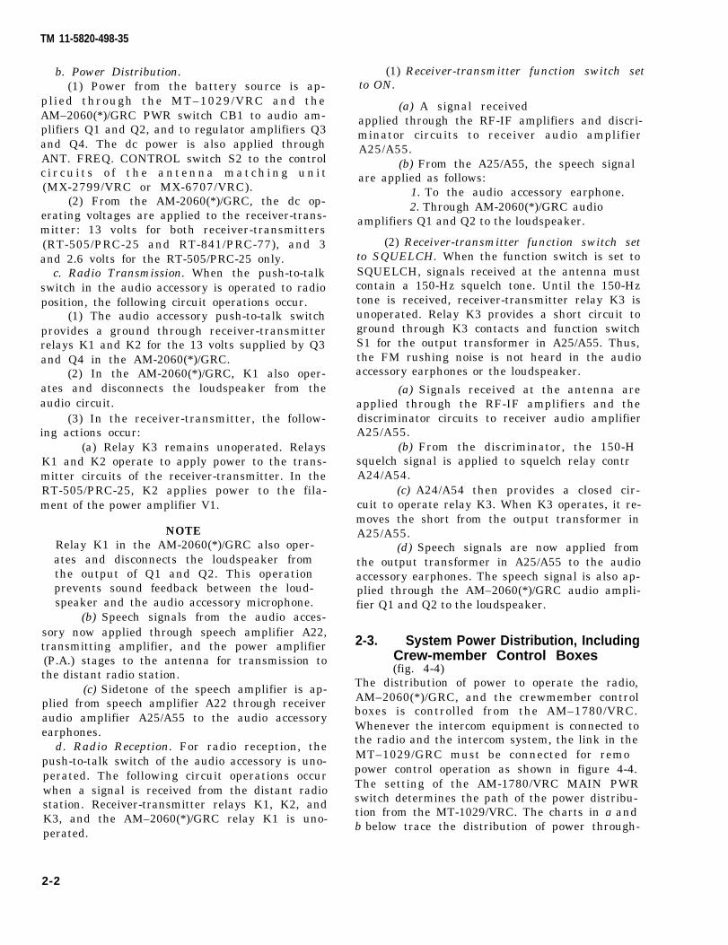
b. Power Distribution.(1) Power from the battery source is ap-
plied through the MT–1029/VRC and theAM–2060(*)/GRC PWR switch CB1 to audio am-plifiers Q1 and Q2, and to regulator amplifiers Q3and Q4. The dc power is also applied throughANT. FREQ. CONTROL switch S2 to the controlc i r c u i t s o f t h e a n t e n n a m a t c h i n g u n i t(MX-2799/VRC or MX-6707/VRC).
(2) From the AM-2060(*)/GRC, the dc op-erating voltages are applied to the receiver-trans-mitter: 13 volts for both receiver-transmitters(RT-505/PRC-25 and RT-841/PRC-77), and 3and 2.6 volts for the RT-505/PRC-25 only.
c. Radio Transmission. When the push-to-talkswitch in the audio accessory is operated to radioposition, the following circuit operations occur.
(1) The audio accessory push-to-talk switchprovides a ground through receiver-transmitterrelays K1 and K2 for the 13 volts supplied by Q3and Q4 in the AM-2060(*)/GRC.
(2) In the AM-2060(*)/GRC, K1 also oper-ates and disconnects the loudspeaker from theaudio circuit.
(3) In the receiver-transmitter, the follow-ing actions occur:
(a) Relay K3 remains unoperated. RelaysK1 and K2 operate to apply power to the trans-mitter circuits of the receiver-transmitter. In theRT-505/PRC-25, K2 applies power to the fila-ment of the power amplifier V1.
NOTERelay K1 in the AM-2060(*)/GRC also oper-ates and disconnects the loudspeaker fromthe output of Q1 and Q2. This operationprevents sound feedback between the loud-speaker and the audio accessory microphone.
(b) Speech signals from the audio acces-sory now applied through speech amplifier A22,transmitting amplifier, and the power amplifier(P.A.) stages to the antenna for transmission tothe distant radio station.
(c) Sidetone of the speech amplifier is ap-plied from speech amplifier A22 through receiveraudio amplifier A25/A55 to the audio accessoryearphones.
d. Radio Reception. For radio reception, thepush-to-talk switch of the audio accessory is uno-perated. The following circuit operations occurwhen a signal is received from the distant radiostation. Receiver-transmitter relays K1, K2, andK3, and the AM–2060(*)/GRC relay K1 is uno-perated.
(1) Receiver-transmitter function switch setto ON.
(a) A signal receivedapplied through the RF-IF amplifiers and discri-minator circuits to receiver audio amplifierA25/A55.
(b) From the A25/A55, the speech signalare applied as follows:
1. To the audio accessory earphone.2. Through AM-2060(*)/GRC audio
amplifiers Q1 and Q2 to the loudspeaker.
(2) Receiver-transmitter function switch setto SQUELCH. When the function switch is set toSQUELCH, signals received at the antenna mustcontain a 150-Hz squelch tone. Until the 150-Hztone is received, receiver-transmitter relay K3 isunoperated. Relay K3 provides a short circuit toground through K3 contacts and function switchS1 for the output transformer in A25/A55. Thus,the FM rushing noise is not heard in the audioaccessory earphones or the loudspeaker.
(a) Signals received at the antenna areapplied through the RF-IF amplifiers and thediscriminator circuits to receiver audio amplifierA25/A55.
(b) From the discriminator, the 150-Hsquelch signal is applied to squelch relay contrA24/A54.
(c) A24/A54 then provides a closed cir-cuit to operate relay K3. When K3 operates, it re-moves the short from the output transformer inA25/A55.
(d) Speech signals are now applied fromthe output transformer in A25/A55 to the audioaccessory earphones. The speech signal is also ap-plied through the AM–2060(*)/GRC audio ampli-fier Q1 and Q2 to the loudspeaker.
2-3. System Power Distribution, IncludingCrew-member Control Boxes(fig. 4-4)
The distribution of power to operate the radio,AM–2060(*)/GRC, and the crewmember controlboxes is controlled from the AM–1780/VRC.Whenever the intercom equipment is connected tothe radio and the intercom system, the link in theMT–1029/GRC must be connected for remopower control operation as shown in figure 4-4.The setting of the AM-1780/VRC MAIN PWRswitch determines the path of the power distribu-tion from the MT-1029/VRC. The charts in a andb below trace the distribution of power through-
2-2
TM 11-5820-498-35
TM 11--5820-498-35
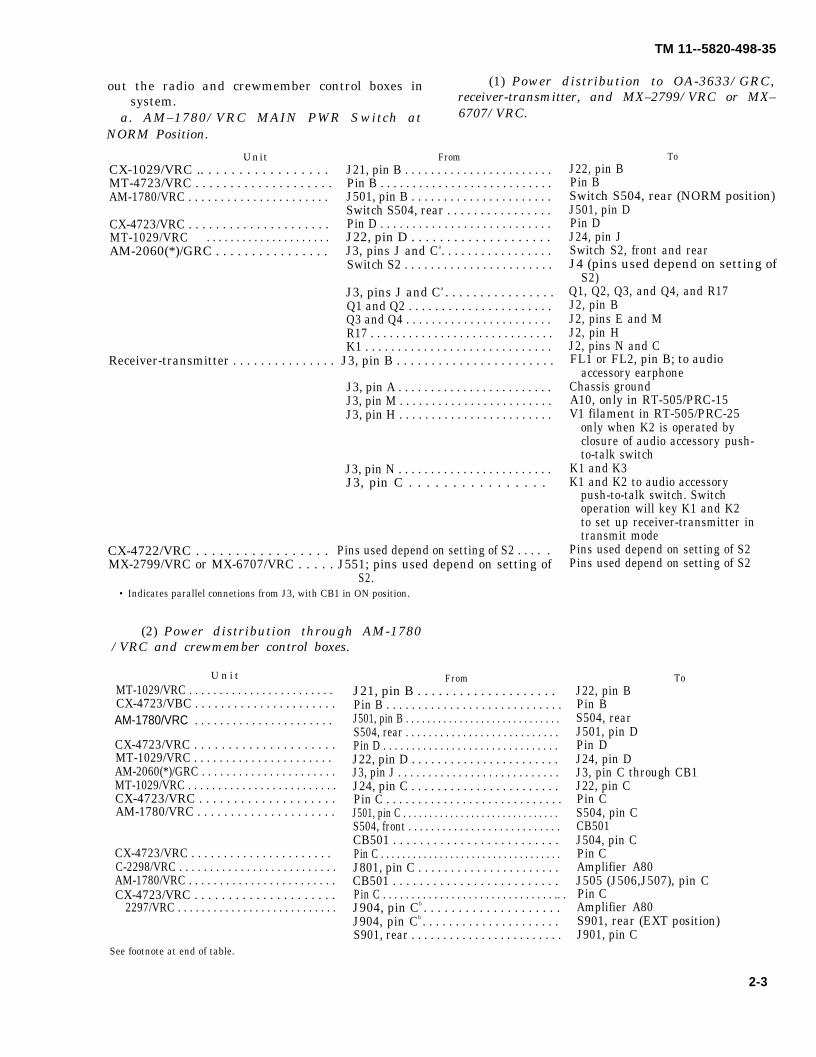
out the radio and crewmember control boxes in (1) Power distribution to OA-3633/GRC,
system. receiver-transmitter, and MX–2799/VRC or MX–
a. AM–1780/VRC MAIN PWR Switch at 6707/VRC.
NORM Position.
FromCX-1029/VRC .. . . . . . . . . . . . . . . . . J21, pin B . . . . . . . . . . . . . . . . . . . . . . .MT-4723/VRC . . . . . . . . . . . . . . . . . . . . Pin B . . . . . . . . . . . . . . . . . . . . . . . . . . .AM-1780/VRC . . . . . . . . . . . . . . . . . . . . . . J501, pin B . . . . . . . . . . . . . . . . . . . . . .
Switch S504, rear . . . . . . . . . . . . . . . .CX-4723/VRC . . . . . . . . . . . . . . . . . . . . . Pin D . . . . . . . . . . . . . . . . . . . . . . . . . . .MT-1029/VRC . . . . . . . . . . . . . . . . . . . . . J22, pin D . . . . . . . . . . . . . . . . . . . .AM-2060(*)/GRC . . . . . . . . . . . . . . . . J3, pins J and Ca. . . . . . . . . . . . . . . . .
Switch S2 . . . . . . . . . . . . . . . . . . . . . . .
J3, pins J and Ca . . . . . . . . . . . . . . . .Q1 and Q2 . . . . . . . . . . . . . . . . . . . . . .Q3 and Q4 . . . . . . . . . . . . . . . . . . . . . . .R17 . . . . . . . . . . . . . . . . . . . . . . . . . . . . .K1 . . . . . . . . . . . . . . . . . . . . . . . . . . . . .
Receiver-transmitter . . . . . . . . . . . . . . . J3, pin B . . . . . . . . . . . . . . . . . . . . . . .
J3, pin A . . . . . . . . . . . . . . . . . . . . . . . .J3, pin M . . . . . . . . . . . . . . . . . . . . . . . .J3, pin H . . . . . . . . . . . . . . . . . . . . . . . .
J3, pin N . . . . . . . . . . . . . . . . . . . . . . . .J3, pin C . . . . . . . . . . . . . . . .
CX-4722/VRC . . . . . . . . . . . . . . . . . Pins used depend on setting of S2 . . . . .MX-2799/VRC or MX-6707/VRC . . . . . J551; pins used depend on setting of
S2.• Indicates parallel connetions from J3, with CB1 in ON position.
(2) Power distribution through AM-1780/VRC and crewmember control boxes.
MT-1029/VRC . . . . . . . . . . . . . . . . . . . . . . . . CX-4723/VBC . . . . . . . . . . . . . . . . . . . . . .
CX-4723/VRC . . . . . . . . . . . . . . . . . . . . .MT-1029/VRC . . . . . . . . . . . . . . . . . . . . . . AM-2060(*)/GRC . . . . . . . . . . . . . . . . . . . . . .MT-1029/VRC . . . . . . . . . . . . . . . . . . . . . . . . .CX-4723/VRC . . . . . . . . . . . . . . . . . . . .AM-1780/VRC . . . . . . . . . . . . . . . . . . . . .
CX-4723/VRC . . . . . . . . . . . . . . . . . . . . . . C-2298/VRC . . . . . . . . . . . . . . . . . . . . . . . . . .AM-1780/VRC . . . . . . . . . . . . . . . . . . . . . . . .CX-4723/VRC . . . . . . . . . . . . . . . . . . . . .
2297/VRC . . . . . . . . . . . . . . . . . . . . . . . . . . .
FromJ21, pin B . . . . . . . . . . . . . . . . . . . . Pin B . . . . . . . . . . . . . . . . . . . . . . . . . . . .J501, pin B . . . . . . . . . . . . . . . . . . . . . . . . . . . . .S504, rear . . . . . . . . . . . . . . . . . . . . . . . . . . .Pin D . . . . . . . . . . . . . . . . . . . . . . . . . . . . . . .J22, pin D . . . . . . . . . . . . . . . . . . . . . . .J3, pin J . . . . . . . . . . . . . . . . . . . . . . . . . . .J24, pin C . . . . . . . . . . . . . . . . . . . . . . .Pin C . . . . . . . . . . . . . . . . . . . . . . . . . . . .J501, pin C . . . . . . . . . . . . . . . . . . . . . . . . . . . . . .S504, front . . . . . . . . . . . . . . . . . . . . . . . . . . . CB501 . . . . . . . . . . . . . . . . . . . . . . . . .Pin C . . . . . . . . . . . . . . . . . . . . . . . . . . . . . . . . . .J801, pin C . . . . . . . . . . . . . . . . . . . . . .CB501 . . . . . . . . . . . . . . . . . . . . . . . . .Pin C . . . . . . . . . . . . . . . . . . . . . . . . . . . . . . .. .J904, pin Cb . . . . . . . . . . . . . . . . . . . . J904, pin Cb . . . . . . . . . . . . . . . . . . . . .S901, rear . . . . . . . . . . . . . . . . . . . . . . . .
ToJ22, pin BPin BSwitch S504, rear (NORM position)J501, pin DPin DJ24, pin JSwitch S2, front and rearJ4 (pins used depend on setting of
S2)Q1, Q2, Q3, and Q4, and R17J2, pin BJ2, pins E and MJ2, pin HJ2, pins N and CFL1 or FL2, pin B; to audio
accessory earphoneChassis groundA10, only in RT-505/PRC-15V1 filament in RT-505/PRC-25
only when K2 is operated byclosure of audio accessory push-to-talk switch
K1 and K3K1 and K2 to audio accessory
push-to-talk switch. Switchoperation will key K1 and K2to set up receiver-transmitter intransmit mode
Pins used depend on setting of S2Pins used depend on setting of S2
ToJ22, pin BPin BS504, rearJ501, pin DPin DJ24, pin DJ3, pin C through CB1J22, pin CPin CS504, pin CCB501J504, pin CPin CAmplifier A80J505 (J506,J507), pin CPin CAmplifier A80S901, rear (EXT position)J901, pin C
See footnote at end of table.
2-3
U n i t
Unit
AM-1780/VRC . . . . . . . . . . . . . . . . . . . . . .
TM 11-5820-498-35
Unit From To
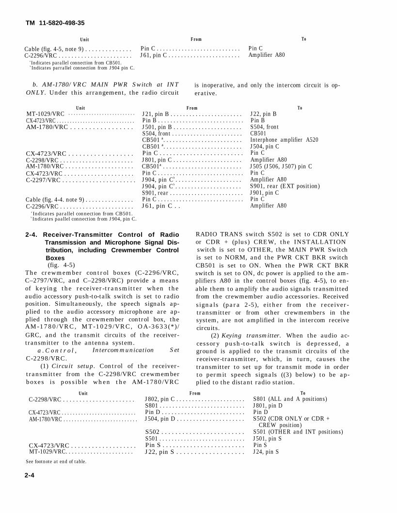
Cable (fig. 4-5, note 9) . . . . . . . . . . . . . . Pin C . . . . . . . . . . . . . . . . . . . . . . . . . . . Pin CC-2296/VRC . . . . . . . . . . . . . . . . . . . . . . . J61, pin C . . . . . . . . . . . . . . . . . . . . . . . Amplifier A80
a Indicates parallel connection from CB501.b Indicates parrallel connection from J904 pin C.
b. AM-1780/VRC MAIN PWR Switch at INT is inoperative, and only the intercom circuit is op-ONLY. Under this arrangement, the radio circuit erative.
Unit From ToMT-1029/VRC J21, pin B . . . . . . . . . . . . . . . . . . . . . . . J22, pin BCX-4723/VRC . . . . . . . . . . . . . . . . . . . . . . . . . . . . . . Pin B . . . . . . . . . . . . . . . . . . . . . . . . . . . . Pin BAM-1780/VRC . . . . . . . . . . . . . . . . . J501, pin B . . . . . . . . . . . . . . . . . . . . . . S504, front
S504, front . . . . . . . . . . . . . . . . . . . . . . . CB501CB501 ª. . . . . . . . . . . . . . . . . . . . . . . . . Interphone amplifier A520CB501 ª. . . . . . . . . . . . . . . . . . . . . . . . . J504, pin C
CX-4723/VRC . . . . . . . . . . . . . . . . . . Pin C . . . . . . . . . . . . . . . . . . . . . . . . . Pin CC-2298/VRC . . . . . . . . . . . . . . . . . . . . . . . J801, pin C . . . . . . . . . . . . . . . . . . . . . . Amplifier A80AM-1780/VRC . . . . . . . . . . . . . . . . . . . . . CB501ª . . . . . . . . . . . . . . . . . . . . . . . . . J505 (J506, J507) pin CCX-4723/VRC . . . . . . . . . . . . . . . . . . . . . Pin C . . . . . . . . . . . . . . . . . . . . . . . . . . . . Pin CC-2297/VRC . . . . . . . . . . . . . . . . . . . . . . J904, pin Cb . . . . . . . . . . . . . . . . . . . . . Amplifier A80
J904, pin Cb . . . . . . . . . . . . . . . . . . . . . S901, rear (EXT position)S901, rear . . . . . . . . . . . . . . . . . . . . . . . . J901, pin C
Cable (fig. 4-4. note 9) . . . . . . . . . . . . . . . Pin C . . . . . . . . . . . . . . . . . . . . . . . . . . . . Pin CC-2296/VRC . . . . . . . . . . . . . . . . . . . . . . . J61, pin C . .
a Indicates parallel connection from CB501.b Indicates paallel connection from J904, pin C.
2-4. Receiver-Transmitter Control of RadioTransmission and Microphone Signal Dis-tribution, including Crewmember ControlBoxes(fig. 4-5)
The crewmember control boxes (C-2296/VRC,C–2797/VRC, and C–2298/VRC) provide a meansof keying the receiver-transmitter when theaudio accessory push-to-talk switch is set to radioposition. Simultaneously, the speech signals ap-plied to the audio accessory microphone are ap-plied through the crewmember control box, theAM-1780/VRC, MT-1029/VRC, OA-3633(*) /GRC, and the transmit circuits of the receiver-transmitter to the antenna system.
a . C o n t r o l , Intercommunication SetC-2298/VRC.
(1) Circuit setup. Control of the receiver-transmitter from the C-2298/VRC crewmemberboxes is possible when the AM-1780/VRC
Unit
Amplifier A80
RADIO TRANS switch S502 is set to CDR ONLYor CDR + (plus) CREW, the INSTALLATIONswitch is set to OTHER, the MAIN PWR Switchis set to NORM, and the PWR CKT BKR switchCB501 is set to ON. When the PWR CKT BKRswitch is set to ON, dc power is applied to the am-plifiers A80 in the control boxes (fig. 4-5), to en-able them to amplify the audio signals transmittedfrom the crewmember audio accessories. Receivedsignals (para 2-5), either from the receiver-transmitter or from other crewmembers in thesystem, are not amplified in the intercom receivecircuits.
(2) Keying transmitter. When the audio ac-cessory push-to-talk switch is depressed, aground is applied to the transmit circuits of thereceiver-transmitter, which, in turn, causes thetransmitter to set up for transmit mode in orderto permit speech signals ((3) below) to be ap-plied to the distant radio station.
From ToC-2298/VRC . . . . . . . . . . . . . . . . . . . . . . J802, pin C . . . . . . . . . . . . . . . . . . . . . .
S801 . . . . . . . . . . . . . . . . . . . . . . . . . . .CX-4723/VRC . . . . . . . . . . . . . . . . . . . . . . . . . . . Pin D . . . . . . . . . . . . . . . . . . . . . . . . . .AM-1780/VRC . . . . . . . . . . . . . . . . . . . . . . . . . . . J504, pin D . . . . . . . . . . . . . . . . . . . . .
S502 . . . . . . . . . . . . . . . . . . . . . . . .S501 . . . . . . . . . . . . . . . . . . . . . . . . . . . .
CX-4723/VRC . . . . . . . . . . . . . . . . . . . Pin S . . . . . . . . . . . . . . . . . . . . . . . .MT-1029/VRC. . . . . . . . . . . . . . . . . . . . . . J22, pin S . . . . . . . . . . . . . . . . . . .
S801 (ALL and A positions)J801, pin DPin DS502 (CDR ONLY or CDR +
CREW position)S501 (OTHER and INT positions)J501, pin SPin SJ24, pin S
See footnote at end of table.
2-4
. . . . . . . . . . . . . . . . . . . . . . . . . .
Unit From
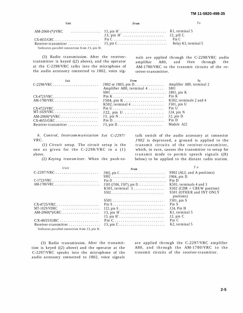
AM-2060-(*)/VRC . . . . . . . . . . . . . . . . . . . . J3, pin Ha . . . . . . . . . . . . . . . . . . . . . . . . . K1, terminal 5J3, pin Ha . . . . . . . . . . . . . . . . . . . J2, pill C
CX-4655/GRC . . . . . . . . . . . . . . . . . . . . . . . . . . Pin C . . . . . . . . . . . . . . . . . . . . . . . . . . . . . . . Pin CReceiver-transmitter . . . . . . . . . . . . . . . . . J3, pin C . . . . . . . . . . . . . . . . . . . . . . . . . . . . Relay K3, terminal 5
aIndicates parallel connection from J3, pin H.
(3) Radio transmission. After the receiver- nals are applied through the C-2298/VRC audiotransmitter is keyed ((2) above), and the operator amplifier A80, and then through theat the C-2298/VRC talks into the microphone of AM-1780/VRC to the transmit circuits of the re-the audio accessory connected to J802, voice sig- ceiver-transmitter.
C-2298/VRC . . . . . . . . . . . . . . . . . . . . . . . .
CX-4723/VRC . . . . . . . . . . . . . . . . . . . . . . . . . . .AM-1780/VRC . . . . . . . . . . . . . . . . . . . . . . . .
CX-4723/VRC . . . . . . . . . . . . . . . . . . . . . . . .MT-1029/VRC . . . . . . . . . . . . . . . . . . . . . . . .AM-2060(*)/VRC . . . . . . . . . . . . . . . . . .CX-4655/GRC . . . . . . . . . . . . . . . . . . . . . . Receiver-transmitter . . . . . . . . . . . . . . . .
FromJ802 or J803, pin D . . . . . . . . . . . . . . .Amplifier A80, terminal 4 . . . . . . .S801 . . . . . . . . . . . . . . . . . . . . . . . . . . . . . . . . .Pin K . . . . . . . . . . . . . . . . . . . . . . . . . . .J504, pin K . . . . . . . . . . . . . . . . . . .K502, terminal 4 . . . . . . . . . . . . . . . . .Pin U . . . . . . . . . . . . . . . . . . . . . . . . . . .J22, pin U . . . . . . . . . . . . . .J3, pin N . . . . . . . . . . . . . . . . . . . . . . . .Pin D . . . . . . . . . . . . . . . . . . . . . . . . . . .J3, pin D . . . . . . . . . . . . . . . . . . . . . . . .
ToAmplifier A80, terminal 2S801J801, pin KPin KK502, terminals 2 and 4J501, pin UPin UJ24, pin NJ2, pin DPin DModule A22
h. Control, Intercommunication Set C-2297/ talk switch of the audio accessory at connectorVRC. J902 is depressed, a ground is applied to the
(1) Circuit setup. The circuit setup is the transmit circuits of the receiver-transmitter,one as given for the C-2298/VRC in a (1) which, in turn, causes the transmitter to setup forabove. transmit mode to permit speech signals ((8)
(2) Keying transmitter. When the push-to- below) to be applied to the distant radio station.
C-2297/VRC . . . . . . . . . . . . . . . . . . . . .
C-1723/VRC . . . . . . . . . . . . . . . . . . . . . . . . . AM-1780/VRC . . . . . . . . . . . . . . . . . . . . . . . . . . .
CX-4725/VRC . . . . . . . . . . . . . . . . . . . . .MT-1029/VDRC . . . . . . . . . . . . . . . . . . . .AM-2060(*)/GRC . . . . . . . . . . . . . . . . . .
CX-4655/GBC . . . . . . . . . . . . . . . . . . .Receiver-transmitter . . . . . . . . . . . . . . . .
a Indicates paralled connection from J3, pin H.
FromJ902, pin C . . . . . . . . . . . . . . . . . . . . . . . . . . .S902 . . . . . . . . . . . . . . . . . . . . . . . . . . . . . . . .Pin D . . . . . . . . . . . . . . . . . . . . . . . . . . . . . . . .J505 (J506, J507), pin D . . . . . . . . . . . . . . .K501, terminal 3 . . . . . . . . . . . . . . . . S502 . . . . . . . . . . . . . . . . . . . . . . . . . . . . . . .
S501 . . . . . . . . . . . . . . . . . . . . . . . . . . Pin S . . . . . . . . . . . . . . . . . . . . . . . . . . . . J22, pin S . . . . . . . . . . . . . . . . . . . . . . . . .J3, pin Ha . . . . . . . . . . . . . . . . . . . . . . .J3, pin Ha . . . . . . . . . . . . . . . . . . . . . . . . . . Pin C . . . . . . . . . . . . . . . . . . . . . . . . J3, pin C . . . . . . . . . . . . . . . . . . . . . . . .
S902 (ALL and A positions)J904, pin DPin DK501, terminals 4 and 3S502 (CDR + CREW position)S501 (OTHER and INT ONLY
positions)J501, pin SPin SJ24, Pin HK1, terminal 5J2, pin CPin CK2, terminal 5
(3) Radio transmission. After the tranamit- are applied through the C-2297/VRC amplifiertion is keyed ((2) above) and the operator at the A80, and through the AM-1780/VRC to theC-2297/VRC speaks into the microphone of the transmit circuits of the receiver-trasmitter.audio accessory connected to J802, voice signals
TM 11-5820-498-35
To
Unit
Unit
2-5
T o
TM 11-5820-498-35
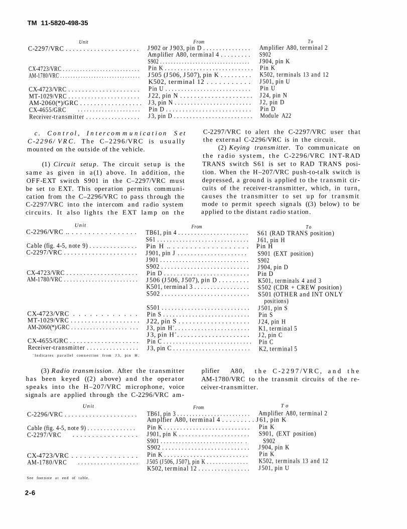
UnitC-2297/VRC . . . . . . . . . . . . . . . . . . . . .
CX-4723/VRC . . . . . . . . . . . . . . . . . . . . . . . . . . . AM-1780/VRC . . . . . . . . . . . . . . . . . . . . . . . . . . . . . . .
CX-4723/VRC . . . . . . . . . . . . . . . . . . . . .MT-1029/VRC . . . . . . . . . . . . . . . . . . . . . .AM-2060(*)/GRC . . . . . . . . . . . . . . . . . .CX-4655/GRC . . . . . . . . . . . . . . . . . . . . .Receiver-transmitter . . . . . . . . . . . . . . . . .
FromJ902 or J903, pin D . . . . . . . . . . . . . . .Amplifier A80, terminal 4 . . . . . . . . .S902 . . . . . . . . . . . . . . . . . . . . . . . . . . . . . . . . . Pin K . . . . . . . . . . . . . . . . . . . . . . . . . . . .J505 (J506, J507), pin K . . . . . . . . .K502, terminal 12 . . . . . . . . . . .Pin U . . . . . . . . . . . . . . . . . . . . . . . . . . .J22, pin N . . . . . . . . . . . . . . . . . . . . .J3, pin N . . . . . . . . . . . . . . . . . . . . . . . .Pin D . . . . . . . . . . . . . . . . . . . . . . . . . .J3, pin D . . . . . . . . . . . . . . . . . . . . . . . . .
c . C o n t r o l , I n t e r c o m m u n i c a t i o n S e tC-2296/VRC. The C–2296/VRC is usuallymounted on the outside of the vehicle.
(1) Circuit setup. The circuit setup is thesame as given in a(1) above. In addition, theOFF-EXT switch S901 in the C–2297/VRC mustbe set to EXT. This operation permits communi-cation from the C–2296/VRC to pass through theC-2297/VRC into the intercom and radio system
ToAmplifier A80, terminal 2S902J904, pin KPin KK502, terminals 13 and 12J501, pin UPin UJ24, pin NJ2, pin DPin DModule A22
C-2297/VRC to alert the C-2297/VRC user thatthe external C-2296/VRC is in the circuit.
(2) Keying transmitter. To communicate onthe radio system, the C-2296/VRC INT-RADTRANS switch S61 is set to RAD TRANS posi-tion. When the H–207/VRC push-to-talk switch isdepressed, a ground is applied to the transmit cir-cuits of the receiver-transmitter, which, in turn,causes the transmitter to set up for transmitmode to permit speech signals ((3) below) to be
circuits. It also lights the EXT lamp on the applied to the distant radio station.
C-2296/VRC .. . . . . . . . . . . . . . . . .
Cable (fig. 4-5, note 9) . . . . . . . . . . . . . .C-2297/VRC . . . . . . . . . . . . . . . . . . . . .
CX-4723/VRC . . . . . . . . . . . . . . . . . . . . .AM-1780/VRC . . . . . . . . . . . . . . . . . . . . . . . .
CX-4723/VRC . . . . . . . . . . . .MT-1029/VRC . . . . . . . . . . . . . . . . . . . .AM-2060(*)/GRC . . . . . . . . . . . . . . . . . . . . .
CX-4655/GRC . . . . . . . . . . . . . . . . . . . .Receiver-transmitter . . . . . . . . . . . . . . . .
a Indicates parallel connection from J3, pin H.
FromTB61, pin 4 . . . . . . . . . . . . . . . . . . . . . .S61 . . . . . . . . . . . . . . . . . . . . . . . . . . . . .Pin H .. . . . . . . . . . . . . . . . . . .J901, pin J . . . . . . . . . . . . . . . . . . . . . J901 . . . . . . . . . . . . . . . . . . . . . . . . . . . .S902 . . . . . . . . . . . . . . . . . . . . . . . . . . .Pin D . . . . . . . . . . . . . . . . . . . . . . . . . .J506 (J506, J507), pin D . . . . . . . . .K501, terminal 3 . . . . . . . . . . . . . . . . .S502 . . . . . . . . . . . . . . . . . . . . . . . . . . .
S501 . . . . . . . . . . . . . . . . . . . . . . . . . . .Pin S . . . . . . . . . . . . . . . . . . . . . . . . . . .J22, pin S . . . . . . . . . . . . . . . . . . . .J3, pin Ha . . . . . . . . . . . . . . . . . . . . . . .J3, pin Ha . . . . . . . . . . . . . . . . . . . . .Pin C . . . . . . . . . . . . . . . . . . . . . . . . . . . .J3, pin C . . . . . . . . . . . . . . . . . . . . . . . .
ToS61 (RAD TRANS position)J61, pin H
S901 (EXT position)S902J904, pin DPin DK501, terminals 4 and 3S502 (CDR + CREW position)S501 (OTHER and INT ONLY
positions)J501, pin SPin SJ24, pin HK1, terminal 5J2, pin CPin CK2, terminal 5
(3) Radio transmission. After the transmitter plifier A80, t h e C - 2 2 9 7 / V R C , a n d t h ehas been keyed ((2) above) and the operator AM-1780/VRC to the transmit circuits of the re-speaks into the H–207/VRC microphone, voice ceiver-transmitter.signals are applied through the C-2296/VRC am-
C-2296/VRC . . . . . . . . . . . . . . . . . . . . . From
TB61, pin 3 . . . . . . . . . . . . . . . . . . . . . . . . Amplifier A80, terminal 2Amplfier A80, terminal 4 . . . . . . . . . J61, pin K
Cable (fig. 4-5, note 9) . . . . . . . . . . . . . . . Pin K . . . . . . . . . . . . . . . . . . . . . . . . . . . Pin KC-2297/VRC . . . . . . . . . . . . . . . . . J901, pin K . . . . . . . . . . . . . . . . . . . . . . S901, (EXT position)
S901 . . . . . . . . . . . . . . . . . . . . . . . . . . . . S902S902 . . . . . . . . . . . . . . . . . . . . . . . . . . . J904, pin K
CX-4723/VRC . . . . . . . . . . . . . . . . Pin K . . . . . . . . . . . . . . . . . . . . . . . . . . Pin KAM-1780/VRC . . . . . . . . . . . . . . . . . . . J505 (J506, J507), pin K . . . . . . . . . . . . . . K502, terminals 13 and 12
K502, terminal 12 . . . . . . . . . . . . . . . . J501, pin USee footnote at end of table.
2-6
T oUnit
Unit
Pin H
TM 11-5820-498-35
Unit From TO
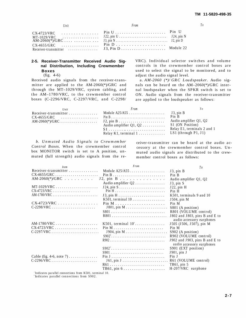
CX-4723/VRC Pin U . . . . . . . . . . . . . . . . . . . . . . . Pin U. . . . . . . . .. . . . . . .MT-1029/VRC . . . . . . . . . . . . . . . . . J22, pin U . . . . . . . . . . . . . . . . . . . . . . . . . . . J24, pin NAM-2060(*)/GRC . . . . . . . . . . . . . . . J3, pin N . . . . . . . . . . . . . . . . . . . . . . . . . . . . . . . . . J2, pin DCX-4655/GRC . . . . . . . . . . . . . . . . . . Pin D . . . . . . . . . . . . . . . . . . .Receiver-transmitter . . . . . . . . . . . . . . . J3, Pin D . . . . . . . . . . . . . . . . . . . . . Module 22
2-5. Receiver-Transmitter Received Audio Sig- nal Distribution, Including Crewmember
Boxes(fig. 4-6)
Received audio signals from the receiver-trans-mitter are applied to the AM-2060(*)/GRC andthrough the MT–1029/VRC, system cabling, andthe AM–1780/VRC, to the crewmember controlboxes (C-2296/VRC, C-2297/VRC, and C-2298/
VRC). Individual selector switches and volumecontrols in the crewmember control boxes areused to select the signal to be monitored, and toadjust the audio signal level.
a. AM-2060 (*)/GRC Loudspeaker. Audio sig-nals can be heard on the AM–2060(*)/GRC inter-nal loudspeaker when the SPKR switch is set toON. Audio signals from the receiver-transmitterare applied to the loudspeaker as follows:
Unit From ToReceiver-transmitter . . . . . . . . . . . . . . Module A25/A55 . . . . . . . . . . . . . . . . . . . J3, pin BCX-4655/GRC . . . . . . . . . . . . . . . . . . . . . Pin B . . . . . . . . . . . . . . . . . . . . . . . . . . . . . . . . . . . Pin BAM-2060(*)/GRC . . . . . . . . . . . . . . . . . . . J2, pin B . . . . . . . . . . . . . . . . . . . . . . . Audio amplifier Q1, Q2
Audio amplifier Q1, Q2 . . . . . . . . . . . S1 (ON Position)S1 . . . . . . . .. . . . . . . . . . . . . . . . . . . Relay E1, terminals 2 and 1Relay K1, terminal 1 . . . . . . . . . . . . . LS1 (through P1, J1)
b. Unmuted Audio Signals to Crewmember ceiver-transmitter can be heard at the audio ac-Control Boxes. When the crewmember control cessory at the crewmember control boxes. Un-box MONITOR switch is set to A position, un- muted audio signals are distributed to the crew-muted (full strength) audio signals from the re- member control boxes as follows:
ItemReceiver-transmitter . . . . . . . . . . . . . . Module A25/A55 . . . . . . . . . . . . . . . . . .CX-4655/GRC . . . . . . . . . . . . . . . . . . . . . . Pin B . . . . . . . . . . . . . . . . . . . . . . . . . . .AM-2060(*)/GRC . . . . . . . . . J2, pin B . . . . . . . . . . . . . .
Audio amplifier Q2 . . . . . . . . . . . . . . .MT-1029/VRC . . . . . . . . . . . . . . . . . . . . . J24, pin S . . . . . . . . . . . . . . . . . . . . . . . .CX-4723/VRC . . . . . . . . . . . . . . . . . . . . . Pin H . . . . . . . . . . . . . . . . . . . . . . . . . . . .AM-1780/VRC . . . . . . . . . . . . . . . . . . . . . . . . . . J3, pin H . . . . . . . . . . . . . . . . . . . . . . . .
K501, terminal 10 . . . . . . . . . . . . . . . . .CX-4723/VRC . . . . . . . . . . . . . . . . Pin M . . . . . . . . . . . . . . . . . . . . .C-2298/VRC . . . . . . . . . . . . . . . . . . . . . . . J801, pin M . . . . . . . . . . . . . . . . . . . . . .
S801 . . . . . . . . . . . . . . . . . . . . . . . . . . . . . . .R801 . . . . . . . . . . . . . . . . . . . . . . . . . . . . .
AM-1780/VRC . . . . . . . . . . . . . . . . . . . . . K501, terminal 10a . . . . . . . . . . . . . . .CX-4723/VRC . . . . . . . . . . . . . . . . . . . . . Pin M . . . . . . . . . . . . . . . . . . . . . . . . . C-2297/VRC . . . . . . . . . . . . . . . . . . . . . . . . . J904, pin M . . . . . . . . . . . . . . . . . . . . . .
S902b . . . . . . . . . . . . . . . . . . . . . . . . . . . . . . . .R902 . . . . . . . . . . . . . . . . . . . . . . . . . . . . . . . . .
S902b . . . . . . . . . . . . . . . . . . . . . . . . . . . . . . .S901 . . . . . . . . . . . . . . . . . . . . . . . . . . . . .
Cable (fig. 4-6, note 7) . . . . . . . . . . . . . . Pin J . . . . . . . . . . . . . . . . . . . . . . . . . . . .C-2296/VRC . . . . . . . . . . . . . . . . . . . . . . . . J61, pin J . . . . . . . . . . . . . . . . . . . . . . . .
R61 . . . . . . . . . . . . . . . . . . . . . . . . . . . .TB61, pin 6 . . . . . . . . . . . . . . . . . . . .
a Indicates parallel connections from K501, terminal 10.b Indicates parallel connections from S902.
ToJ3, pin BPin BAudio amplifier Q1, Q2J3, pin SJ22, pin HPin HK501, terminals 9 and 10J504, pin MPin MS801 (A position)R801 (VOLUME control)J802 and J803, pins B and E to
audio accessory earphonesJ505 (J506, J507), pin MPin MS902 (A position)R902 (VOLUME control)J902 and J903, pins B and E to
audio accessory earphonesS901 (EXT position)J901, pin JPin JR61 (VOLUME control)TB61, pin 5H-207/VRC earphone
2-7
From

TM 11-5820-498-35
c. Muted Audio Signals to Crewmember Con- the crewmembers can be heard over the radiotrol Boxes. When a crewmember control box audio signals, since both sources of audio signalsMONITOR switch is set to ALL position, muted are avaiIable when the crewmember control boxaudio signals (reduced strength by passage MONITOR switch is set to ALL position. Mutedthrough R15 in AM-2060(*)/GRC) can be heard audio signals received at the receiver-transmitterat the audio accessory at each crewmember con- are distributed to the crewmember control boxestrol box. The receiver-transmitter audio signal is as follows:reduced so that the intercom audio signals among
UnitReceiver-transmitter . . . . . . . . . . . . . . . . . .CX-4655/GRO . . . . . . . . . . . . . . . . . . .AM-2060(*)/GRO . . . . . . . . . . . . . . . . . .
CX-4723/VRC . . . . . . . . . . . . . . . . . . . .AM-1780/VRC . . . . . . . . . . . . . . .. . . . . . . .
CX-4723/VRC . . . . . . . . . . . . . . .C-2298/VRC . . . . . . . . . . . . . . . . . . . .
AM-1780/VRC . . . . . . . . . . . . . . . . . . . . . . . .CX-4723/VRC . . . . . . . . .. . . . . . . . .C-2298/VRC . . . . . . . . . . . . . . . . . . . . . .
Cable (fig. 4-6, note 7) . . . . . . . . . . . . . . . . .C-2296/VRC . . . . . . . . . . . . . . . . . . . . . . . . . . .
FromModule A25/A55 . . . . . . . . . . . . . . . Pin B . . . . . . . . . . . . . . . . . . . . . . . . . . . .J2, pin B . . . . . . . . . . . . . . . . . . . . . . . . . . . . Audio amplifier Q2 . . . . . . . . . . . . .R15 . . . . . . . . . . . . . . . . . . . . . . . . . . .Pin K . . . . . . . . . . . . . . . . . . . . . . . . . . . . .J501, pin K . . . . . . . . . . . . . . . . . . . . . . . . . S503 . . . . . . . . . . . . . . . . . . . . . . . . . .K502, terminal 19 . . . . . . . . . . . . . . . . .Interphone amplifier A520a . . . . . . . . .Pin L . . . . . . . . . . . . . . . . . . . . . . . . . . . . . . . . . . .J801, pin L . . . . . . . . . . . . . . . . . . . . . . . . . . . . .S801 . . . . . . . . . . . . . . . . . . . . . . . . . . . . . . . . . .R801 . . . . . . . . . . . . . . . . . . . . . . . . . . . . . . . . . . . .
Interphone amplifier A520a . . . . . . . .Pin L . . . . . . . . . . . . . . . . . . . . . . . . . . . . . . .J904, pin L . . . . . . . . . . . . . . . . . . . . . . . . . . . .
. . . . . . . . . . . . .. . . . . . . . . . . . . . . .. . . . . . . . . . . . . . . . . .
S902b . . . . . . . . . . . . . . . . . . . . . . . . . . . . S901 . . . . . . . . . . . . . . . . . . . . . . . . . . . . . . .Pin J . . . . . . . . . . . . . . . . . . . . . . . . . . .J61, pin J . . . . . . . . . . . . . . . . . . . . . . . . . .R61 . . . . . . . . . . . . . . . . . . . . . . . . . . . .TB61, pin 6 . . . . . . . . . . . . . . . . . . . . . . . . .
a Indicates parallel connections from interphone amplifier A520.b Indicates paralled connections from S902.
ToJ9, pin BPin BAudio amplifier Q1, Q2R15 (muting resistor)J9, pin KPin KS608 (OFF position)K502, terminals 18 and 19Interphone amplifier A520J504, pin LPin LS801 (ALL position)R801 (VOLUME control)J802 and J809, pins B and E to
audio accessory earphoneJ506 (J506, J507), pin LPin LS902 (ALL position)R902 (VOLUME control)J902 and J903, pins B and E, to
audio accessory earphoneS901 (EXT position)J901, pin JPin JR61 (VOLUME control).TB61, pin 5H-207/VRC earphone
Section II. RETRANSMISSION CIRCUIT FUNCTIONING
2-6. Radio Retransmission Circuits, General(fig. 4-7 and 4-8)
a. The receiver-transmitter in the AN/VRC-53,AN/VRC-64, AN/GRC-125, and AN/GRC-160can be connected with another receiver-transmit-ter for the purpose of setting up a radio relay sitefor automatic retransmission of radio signalsfrom radio stations that are too far distant fromeach other for direct radio communication. Theother receiver-transmitter at the relay site can bethe RT-505/PRC-25 or RT-84/PRC-77 (para2-7), or it can be the RT-246(*)/VRC orRT-542(*)/VRRC (para 2-6) from theAN/VRC-12 radio series. (RT-246(*)/VRC andRT-524(*)/VRC represent all models of each re-ceiver-transmitter.)
b. Retransmission Cable Kit MK-456/GRC is
used to provide the connection between the re-ceiver-transmitters at the relay site. TheMK-456/GRC consists of a canvas bag and a 50-foot Cable Assembly, Special Purpose, ElectricalCX-4656/GRC. Two circuit boxes, a choke box,and filter box (fig. 4-7) are included in the cableassembly. An audio accessory can be connected tothe receptacle on the choke box to monitor audiosignals applied through the retransmission cir-cuits. When the two radios at the relay site areset up for providing retransmission to the twodistant radio stations, the keying of one relay sitereceiver-transmitter to send the signals to onedistant radio station is automatically arranged bythe other relay site receiver-transmitter that ireceiving the signal from the other distant radiostation.
S902ªR902
2-8

2-7 Retransmission Using RT-505/PRC-25’s orRT-841/PRG-77's
a. Basic Setup. The CX-4656/GRC connectionbetween the two receiver-transmitters No. 2 andNo. 3 at the relay site is shown in note 5, figure4-7. On the receiver-transmitters, the function
pitches are set to RETRANS. The distant radiostations must be set up for squelch operation inorder to provide the automatic sending of the150-Hz squelch signal when they are keyed fortransmission. When the relay site receiver-trans-mitters are set up for retransmission, the 150-Hzsquelch signal is used to operate relays for auto-matic retransmission and keying of the sendingreceiver-transmitter.
b. Circuit Functioning. Under the setup in aabove, the retransmission circuits perform asgiven in (1) through (8) below.
(1) Before a radio signal is received fromeither distant radio station, the relay site re-ceiver-transmitters are in standby mode. Underthis condition, the audio output transformers inreceiver amplifiers A25/A55 are groundedthrough contacts of squelch relay K1 and func-tion switch S1. Thus, no audio signals can passbetween the relay site radios.
(2) When a signal, including the 150-Hzquelch signal, is received at receiver-transmitter
No. 2, it is applied through RF-IF amplifiers anddiscriminator to receiver audio amplifierA25/A55.
(3) From the discriminator, the 150/Hzsquelch signal is applied to squelch relay controlA24/A54. A24/A54 then provides a closed circuitto operate relay K3. When K3 operates, contact8-3 remove the short from audio output trans-former in A25/A55 ((1) above).
(4) Simultaneously, ground on audio outputtransformer in A25/A55 is provided through thefunction switch and applied through the diode inthe CX-4656/GRC, and through receiver-trans-mitter No. 3 relays K1 and K2 to the battery.Thus, contacts 4-7 of relay K1 provide 10 voltsoperating power to receiver-transmitter No. 3transmitting circuits.
(5) With the transmitting circuits in re-ceiver-transmitter No. 3 in transmit mode, speechsignals now can be applied from receiver-trans-mitter No. 2 through the CX-4656/GRC to re-
ceiver-transmitter No. 3 speech amplifier A22,and through the transmitting amplifier and P.A.stages to the antenna for transmission to radiostation No. 4.
(6) When radio station No. 1 ceases keyingits transmitter, receiver-transmitters No. 3 and
No. 2 go into standby condition as described in(1) above.
(7) When radio station No. 4 keys its trans-mitter and transmits its signals, receiver-trans-mitters No. 3 and No. 2 perform in the samemanner as described in (2) through (5) above.
(8) When an audio accessory is connected tot h e a u d i o a c c e s s o r y r e c e p t a c l e o n t h eCX-4656/GRC network box, the audio accessorycircuits are effectively connected to the outputaudio circuits of receiver-transmitter No. 3 (theone next to the choke box of the CX-4656/GRC48 feet away). Accordingly, the audio accessoryuser can perform the following operations.
(a) Hear the signal being transmittedfrom radio station No. 4 to radio station No. 1.
(b) While receiver-transmitter No. 2 iskeyed (by squelch tone from No. 4), the user cantalk to radio station No. 1.
(c) If the radios are on standby, the usercan key (through pin C) and transmit (throughpin D) over receiver-transmitter No. 3 to No. 4.The reply from radio station No. 4 will be heard(through pin B). The action will also cause thereply to be heard at radio station No. 1
(d) To transmit to radio station No. 1, theuser must transfer the audio accessory to theAUDIO connector on receiver-transmitter No. 2,which is next to the network box of theCX-4656/GRC (2 feet away).
2-8. Retransmission Using Receiver-Transmitters r Radio RT-246(*)/VRC orRT-524(*)/VRC With RT-505/PRC-25or RT-841/PRC-77
NOTERT–246(*)/VRC and RT-524(*)/VRC rep-resent all models of each receiver-transmitter.
When the RT-505/PRC-25 or RT-841/PRC-77 isconnected to the R T - 2 4 6 ( * ) / V R C o rRT-524(*)/VRC for retransmission, the circuitperformance of the radios during retransmissionis similar to that described in paragraph 2-7.Refer to figure 4-8 for the following circuit func-tioning descriptions.
a. Basic Setup. The CX-4656/GRC connectionbetween receiver-transmitters No. 2 and 3 isshown in figure 4-5. On receiver-transmitter No.2, the function switch is set to RETRANS; on re-ceiver-transmitter No. 3, the SQUELCH switch isset to NEW ON or OLD ON, depending on theradio station used at radio station No. 4.
b. Circuit Functioning. Under the setup in aabove, the retransmission circuits function asgiven in (1) through (7) below.
TM 11-5820-498-35
2-9
TM 11-5820-498-35
(1) Before the RF signals are received fromeither distant radio station, the relay site re-ceiver-transmitters are in standby mode. Underthis situation, the output transformers, inA25/A55 in No. 2 and T5001 in No. 3, aregrounded through contacts of their associatedsquelch relays. Thus, no signals can pass betweenthe relay site receiver-transmitters.
(2) When a signal including the 150-Hzsquelch signal is received at receiver-transmitterNo. 2, it is applied through RF-IF amplifiers andthe discriminator to receiver audio amplifierA25/A55.
(3) From the discriminator, the 150-Hzsquelch signal is applied to squelch relay controlA24/A54. A24/A54 then provides a closed circuitto operate relay K3. When K3 operates, contacts8-3 remove the short from output transformer inA25/A55 ((1) above).
(4) Simultaneously, ground on the outputtransformer in A25/A55 is provided throughfunction switch S1 and applied through diodeCR2 in the CX-4656/GRC and through receiver-transmitter No. 3 relays K405 and K401 to the25-volt battery. Thus, contacts 4-7 of K1 provideoperating power continuity to receiver-transmit-ter No. 3 transmitting circuits by the operation ofrelays K405 and K401.
(5) With the transmitting circuits in re-ceiver-transmitter No. 3 in transmit mode, speechsignals can now be applied from receiver-trans-mitter No. 2 A 2 5 / A 5 5 through theCX-4696/GRC to receiver-transmitter No. 3transmit circuits, and to the antenna for trans-mission to radio station No. 4.
(6) When radio station No. 1 ceases keyingits transmitter, receiver-transmitters No. 2 and 3go into standby condition ((1) above).
(7) When radio station No. 4 keys its trans-mitter and transmits its signals, the operation ofthe circuits in receiver-transmitters No. 3 and 2are accomplished as follows:
(a) When a signal including a squelchsignal (150-Hz or noise) is received at receiver-transmitter No. 2, it is applied through the re-ceive circuit.
(b) In the receive circuit, the squelch sig-nal is applied to squelch control A5200, causingsquelch relay K5002 to operate. When K5002 oper-ates, a ground is provided through contacts 2-5of K505, CR303 (in RT–246(*)/VRC), or CR351(in RT-524(*)/VRC), and the CALL lamp to the25-volt battery.
(c) At the same time, the ground is pro-
vided through the CX-4656/GRC (pins E–C)and relays K1 and K2 to the 12.5-15 volt batterin receiver-transmitter No. 2.
(d) With the transmitting circuits in re-ceiver-transmitter No. 2 in transmit mode by theoperations of K1 and K2, speech signals can nowbe applied from T5005 in receiver-transmitterNo. 3 through the CX-4656/GRC (pins E-C) andthe transmitting circuits in receiver-transmitterNo. 2 to the antenna for transmission to radiostation. No.1.
(e) When radio station No. 4 ceases keyingits transmitter, receiver-transmitters No. 3 and 2go into standby condition ((1) above).
(f) Diode CR1 in the C-E circuit of theCX-4656/GRC is provided to keep the two differ-ent battery potentials separated when the re-ceiver-transmitters No. 3 and 2 are in standby.The diode prevents receiver-transmitter No. 2from going into transmit mode by the operationof K1 and K2. Under this condition, the circuitperforms as follows:
NOTEIf the CX-4656/GRC cable connects to thereceiver-transmitters shown in figure 4-8diode CR2 in the C-E circuit would performthe operations described for CR1 below.
1. When receiver-transmitter No. 2 isconnected to another RT-505 /PRC-25 orRT-841/PRC-77, a squelch signal received by No.3 provides a simple ground to the battery in No. 2which causes relays K1 and K2 to operate fortransmission (fig. 4-3 and para 2-7 b(4)).
2. However, when an RT–246(*)/VRCor RT-524(*)/VRC is used as receiver-transmit-ter No. 3, there are two different battery poten-tials, 12.15 volts in No. 2 and 25 volts in No. 3.If there were no diode CR1 in the CX-4656/GRCwhen the receiver-transmitters are in standby,the two batteries would be connected in series (B,fig. 4-8). When two such opposing potentialsmeet, a voltage difference (between 10 and 12.5volts) would be sufficient to operate K1 and K2into transmit mode in receiver-transmitter No. 2.
3. The diode in CX-4656/GRC preventhis extra voltage from operating K1 and K2. Theremaining voltage is blocked because the poten-tial (which takes on the polarities of the 25-voltbattery) would apply a negative potential to theanode of the diode. Thus, no current can flowoperate K1 and K2 in receiver-transmitter No. 2.
2-10
Section Ill. AMPLIFIER-POWER SUPPLY GROUPOA-3633(*)/GRC, CIRCUIT FUNCTIONING
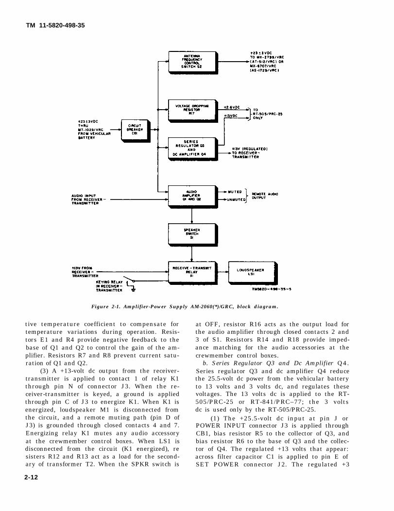
2-9. Amplifier-Power Supply AM-2060(*) /GRC, Block Diagram(fig. 2-1)
The AM-2060(*)/GRC is the main component ofthe OA-3633(*)/GRC; the other component isCable Assembly, Special Purpose, ElectricalCX-4656 /GRC (para 2 -11 , f ig . 3 -5 ) . TheCX-4656/GRC provides dc power and audio sig-nal connection between the receiver-transmittera n d t h e A M - 2 0 6 0 ( * ) / G R C . T h eAM-2060(*)/GRC converts vehicular batterypower (24 ±3 volts dc) to the operating voltagesfor the receiver-transmitter (a below), and am-plification of the receiver-transmitter receivedaudio signals for application to the loudspeakerin the AM–2060(*)/GRC (c(1) below), and tothe crewmember control boxes when they are apart of the system (c(2) below). The vehicularbattery power is also applied to Antenna Match-ing Unit MX–2799/VRC (part of AntennaAT-912/VRC) or to Matching Unit-Base, An-t e n n a M X - 6 7 0 7 / V R C ( p a r t o f A n t e n n aAS-1729/VRRC) (b below).
a. Operating Voltages to Receiver-Transmitter.The nominal 25.5 volts dc from the power source,normally a vehicular battery, is applied throughthe MT-1029/VRC and PWR circuit breaker CB1to series regulator Q3 and dc amplifier Q4, volt-age dropping resistor R17, ANT. FREQ. CON-TROL switch S2, and audio amplifiers Q1 and Q2.
(1) Series regulator Q3 and dc amplifier Q4convert and control the applied 25.5 volts dc to aregulated 13 and 3 volts dc. The 13 volts is foruse in the receiver-transmitter where it is con-verted to 10 volts for the transmit and receivecircuits. In the RT-505/PRC-25 only, the 3 voltsdc is used for interval oscillator A10.
(2) Voltage dropping resistor R17 lowersthe applied 25.5 volts dc to 2.6 ±0.3 volts dc.This voltage is used only in the RT-505/PRC-25as filament voltage for power amplifier V1 whenthe RT-505/PRC-25 is in transmit mode.
b. Operating Vol tages Appl i ed to MX-2799/VRC and MX-6707/VRC. The nominal25.5 volts dc is applied through ANT. FREQ.CONTROL switch S2 to the MX-2799/VRC orMX-6707/VRC. The voltage is used by theMX-2799/VRC and MX-6707/VRC to control thesettings of the matching circuits to provide aclose impedance match for the whip antenna at
the operating frequency of the receiver-transmit-ter. Switch S2 is set to a position that includesthe receiver-transmitter operating frequency.
c. Audio Amplifiers Q1 and Q2. The audio out-put of the receiver-transmitter is applied to audioamplifiers Q1 and Q2.
(1) Remote audio output. Amplifiers Q1 andQ2 amplify the audio signals applied to it fromthe receiver-transmitter and provide two outputs,muted and unmuted. The output signals are ap-plied to crewmember control boxes when they arepart of the system.
(2) Local audio output. The amplifier audiosignals from Q1 and Q2 are also applied throughSPKR switch S1 to receive-transmit relay K1.When the receiver-transmitter is keyed for trans-mission, the keying relay in the receiver-trans-mitter is operated which causes +13 volts dc tobe applied to the winding of keying relay K1 inthe AM-2060(*)/GRC. When K1 operates, it dis-connects the audio signal from the loudspeaker,and thus prevents feedback from the loudspeakerto the audio accessory microphone.
2-10. AM-2060(*)/GRC, Circuit Functioninga. Audio Amplifiers Q1 and Q2. Q1 and Q2
provide amplification of the audio output signalsfrom the receiver-transmitter. The amplifiedaudio output is applied to the AM–2060(*)/GRCloudspeaker and to the audio accessories of theassociated crewmember control boxes.
(1) The audio output signal at pin B of SETPOWER connector J2 is coupled through imped-ance matching transformer T1 to the base ofpush-pull amplifiers Q1 and Q2. The amplifiedaudio output is applied to the primary (terminals1 and 3) of transformer T2. The audio outputacross one-half of the secondary of T2 (terminals4 and 5) is coupled through SPKR switch S1(ON position) and relay K1 (contacts 8 and 2) toloudspeaker LS1. The audio output across thesecondary of T2 (terminals 4 and 6) is appliedthrough limiting resistor R15 to pin K ofPOWER INPUT connector J3 to provide a mutedaudio output; and to pin S of J3 to provide an un-muted audio output to the crewmember controlboxes.
(2) A voltage-dividing network, composedof resistors R2 and R3, and temperature-compen-sating thermistor RT1 provide base-to-emitterbias for Q1 and Q2. Thermistor RT1 has a nega-
2-11
TM 11-5820-498-35
TM 11-5820-498-35
Figure 2-1. Amplifier-Power Supply AM-2060(*)/GRC, block diagram.
tive temperature coefficient to compensate fortemperature variations during operation. Resis-tors E1 and R4 provide negative feedback to thebase of Q1 and Q2 to control the gain of the am-plifier. Resistors R7 and R8 prevent current satu-ration of Q1 and Q2.
(3) A +13-volt dc output from the receiver-transmitter is applied to contact 1 of relay K1through pin N of connector J3. When the re-ceiver-transmitter is keyed, a ground is appliedthrough pin C of J3 to energize K1. When K1 isenergized, loudspeaker M1 is disconnected fromthe circuit, and a remote muting path (pin D ofJ3) is grounded through closed contacts 4 and 7.Energizing relay K1 mutes any audio accessoryat the crewmember control boxes. When LS1 isdisconnected from the circuit (K1 energized), resisters R12 and R13 act as a load for the second-ary of transformer T2. When the SPKR switch is
2-12
at OFF, resistor R16 acts as the output load forthe audio amplifier through closed contacts 2 and3 of S1. Resistors R14 and R18 provide imped-ance matching for the audio accessories at thecrewmember control boxes.
b. Series Regulator Q3 and Dc Amplifier Q4.Series regulator Q3 and dc amplifier Q4 reducethe 25.5-volt dc power from the vehicular batteryto 13 volts and 3 volts dc, and regulates thesevoltages. The 13 volts dc is applied to the RT-505/PRC-25 or RT-841/PRC–77; the 3 voltsdc is used only by the RT-505/PRC-25.
(1) The +25.5-volt dc input at pin J orPOWER INPUT connector J3 is applied throughCB1, bias resistor R5 to the collector of Q3, andbias resistor R6 to the base of Q3 and the collec-tor of Q4. The regulated +13 volts that appear:across filter capacitor C1 is applied to pin E ofSET POWER connector J2. The regulated +3
volts that appears across resistor R19 is appliedto pin M of connector J2.
(2) Bias for Q4 is supplied from a voltage-dividing network composed of R9, R10, R11, andR19 connected between the collector of Q3 andground. Diode CR1 references the emitter of Q4to ground. Diode CR2 references the base of Q4to the + 13-volt output. Regulating action is de-scribed in (3) below.
(3) If the input voltage to Q3 decreases, the13-volt output decreases. Capacitor C1, chargedto the 13-volt level, will begin to discharge as theoutput voltage drops, tending to maintain a con-stant output until the regulating action occurs.As the output voltage decreases, the voltage dropacross R9, R11, and R19 decreases, reducing for-ward bias on Q4, which will decrease its emitter-to-collector current flow. The reduced emitter-to-collector current of Q4 reduces the voltage dropacross resistor R6, increasing the forward bias ofQ3. Emitter-to-collector current flow in Q3 willincrease, decreasing emitter-to-collector resist-ance. The voltage drop through Q3 will decreaseand allow the output to return to the desired levelof 13 volts. If the supply voltage increases to thenormal 25.5-volt level, Q4 will decrease the for-ward bias on Q3 to maintain the constant 13-voltoutput. Resistor R10 is adjusted to produce the
required 13-volt output from the voltage regula-tor.
c. ANT. FREQ. CONTROL Switch S2. T h e+25-volt dc input at pin J of POWER INPUTconnector J3 is applied through PWR circuitcreaker CB1 and switch S2 to the MX–2799/VRCof the AT–912/VRC or to MX-6707/VRC of theAS-1729/VRC, whichever is connected to theAM–2060(*)/GRC. Switch S2 is set to the posi-tion corresponding to the operating frequency ofthe associated receiver-transmitter. CapacitorsC1 through C7 bypass radio frequency (RF) fromthe MX–2799/VRC or MX–6707/VRC to ground.
2-11. Cable Assembly, Special Purpose,Electrical CS-4655/GRC(fig. 3-5)
The CX-4655/GRC (9 or 11 inches long) and theAM-2060(*)/GRC comprise the OA-3633(*)/GRC. The CX-4655/GRC is provided with two ca-ble connectors either of which is connected tot h e S E T P O W E R c o n n e c t o r o n t h eAM–2060(*)/GRC; the other end of the cable isconnected to POWER connector J3 on the re-ceiver-transmitter. The cable carries power, con-trol circuits, and audio signal circuits betweenthe AM–2060(*)/GRC and the receiver-transmit-ter.
2-13
TM 11-5820-498-35

TM 11-5820-498-35
CHAPTER 3
DS AND GS MAINTENANCE
AMPLIFIER-POWER SUPPLY GROUP OA-3633(*) /GRC
NOTEThroughout these procedures, receiver-trans-mitter refers to Receiver-Transmitter, RadioRT–505/PRC-25 which is used in Radio SetsAN/VRC-53 and AN/GRC-125, and to Re-ceiver-Transmitter, Radio RT-841/PRC-77which is used in Radio Sets AN/VRC-64 andAN/GRC-160. Both receiver-transmittersare used with Amplifier-Power SupplyGroup OA-3633(*)/GRC which is also part ofthese radio sets.
Section I. GENERAL TROUBLESHOOTING TECHNIQUES
3-1. Scope of DS and GS Maintenancea. The maintenance procedures in this chapter
are applicable to DS (direct support) and GS(general support) maintenance facilities and sup-plement the organizational maintenance proce-dures described in TM 11-5820-498-12 for theOA-3633(*)/GRC. The systematic troubleshoot-ing procedures which begin with the operationaland equipment performance checks that can beperformed at an organizational maintenance levelare carried to a higher level in this chapter.
b. Refer to paragraph 1-lb for a listing ofpublications that cover the DS and GS mainte-nance level of the components that are part ofthe AN/VRC-53, AN/VRC-64, AN/GRC-125,and AN/GRC–160.
c. Refer to paragraph 1-1c for a listing of pub-lications that cover the DS and GS maintenancelevel of the equipment that is used in conjunctionwith these radio sets.
3-2. Organization of Troubleshooting Proced-ures
a. General. The first step in servicing a defec-tive OA-3633*/GRC is to localize the fault bytracing the trouble to the CX-4655/GRC or tosome part of the AM–2060(*)/GRC. The secondstep is to isolate the fault. Isolation means trac-ing the fault to a defective part responsible forthe abnormal operation. Isolating a fault to a de-fective part on the plug-in assembly of the
AM-2060(*)/GRC is covered in Paragraphs 3-8,3-9, and 3-10. Some faults, such as burned outresistors, arcing, and shorted relay coils andtransformer windings can often be located bysight, smell, or hearing. The majority of thefaults, however, must be isolated by checkingvoltages and resistances.
b. Visual Inspection. The purpose of visualinspection is to locate faults without testing ormeasuring circuits. All visual signs should be ob-served and an attempt made to localize the faultto a particular area.
c. Testing Procedure. After any repair of theCX-4655/GRC or AM-206(*)/GRC, always testit for satisfactory performance of all circuits be-fore returning the equipment to the user or plac-ing it in repaired stock. Refer to paragaphs 3-16through 8-21 for inspection and testing proce-dures. The procedures can also be used to checkthe performance of the equipment before startingto troubleshoot it.
3-3. Test Equipment, Tools, Materials, andPower Sources Required
a. Test Equipment Required.
Item PublicationMultimeter ME-26(*)/Ua . . . . . . . TM 11-6625-200-15Generator, Signal AN/URM-127 TM 11-6625-683-15Voltmeter, Electronic
M E - 8 0 ( * ) / U b . . . . . . . . . TM 11-6625-820-12
Change 2 3-1
TM 11-5820-498-35
Itemb ME-30(*)/U represents ME-30A/U, ME-30B/U, ME-30C/U, a
ME-30E/U.Spectrum Analyzer
a TS-723(*)/U represents TS-723A/U, TS-723B/U, TS-723C/U,TS-723(*)/U a TM 11-5097 TS-723D/U.
a ME-26(*)/U represents ME-26A/U, ME-26B/U, and ME-26C/U. b. Materials and Tools Required.
Item Federal stock No.Resistor, 7.6 ohms (e below).
Identified in
Resistor, 275 ohms (e below).Resistor, 14.5 ohms (e below) . . . . . 5905-279-3521Resider, 300 ohms (e below) . . . . . . . . . 5905-101-8850Mounting MT-1029/VRC . . . . . . 5820-893-1323 . . . . . . . . . . . . . . . . . . . TM 11-5820-498-12Cable Assembly, Power, Electrical CX- 5995-823-2726 . . . . . . . . .. . . . . . . . . . . TM 11-5820-498-12
4720/VRC (10 ft).Cable Assembly, Special Purpose, Elec- 5995-889-1061 . . . . . . . . . . . . . . . TM 11-5820-498-12
trical CX-4655/GRC (e below).Connector, receptacle, electrical (male, 5935-863-5876 . . . . . . . . . . . . . . . . . . . . TM 11-5820-401-35
oval; same as J21 in MT-1029/VRC).Connector, receptacle, electrical (female, 535-853-5944 . . . . . . . . . . . . . . . . . . . . TM 11—5820-401-35
oval; same as J23 in MT-1029/VRC.Connector, receptacle, electrical (female, 5935-853-6044. . . . . . . . . . . . . . . . . . . . TM 11-5820-401-35
elliptical; same as J24 in MT-1029/VRC).
Tool Kit, Electronic Equipment TK-100/G.
Tool Kit, Electronic Equipment TK-106/G.
NotesMT-1029/VRC is required if a fabricated power distribution box (d below) is not avaailable.For fabrication of power distribution box (d below as substitute for the MT-1029/VRC.
c. Power Source Required. (1) Power SupplyPP-6224/U or PP-2953(*)U maybe used
to provide the operating dc voltage for theAM-2060(*)/GRC. The PP-2952(*)/U is normalinternally adjusted to provide 25.2 volts dc output(TM 11-6130-233-12.)
(2) If a dc power source other than theo n e s i n ( 1 ) a b o v e is used, it should becapable of providing a regulated, filtered, dc out-put of 25.5 volts dc at approximately 5 amperes.
(3) If the area in which the testing is beingperformed has difficulty in obtaining an ac powersource that is within the operating ac input volt-age of the PP-2953(*)/U or other power supply),use Variable Power Transformer TF-523/U (fig.3-3). Refer to TM 11-5950-212-15 for installa-tion and maintenance of the TF-523/U.
d. Power Distribution Box. As a substitute forthe MT–1029/VRC which is only used as a con-necting device between the dc power source andthe AM-2060(*)/GRC during testing and trouble-shooting, a power distribution box may be fabri-cated. Refer to paragraph 3-4b for fabrication de-tails.
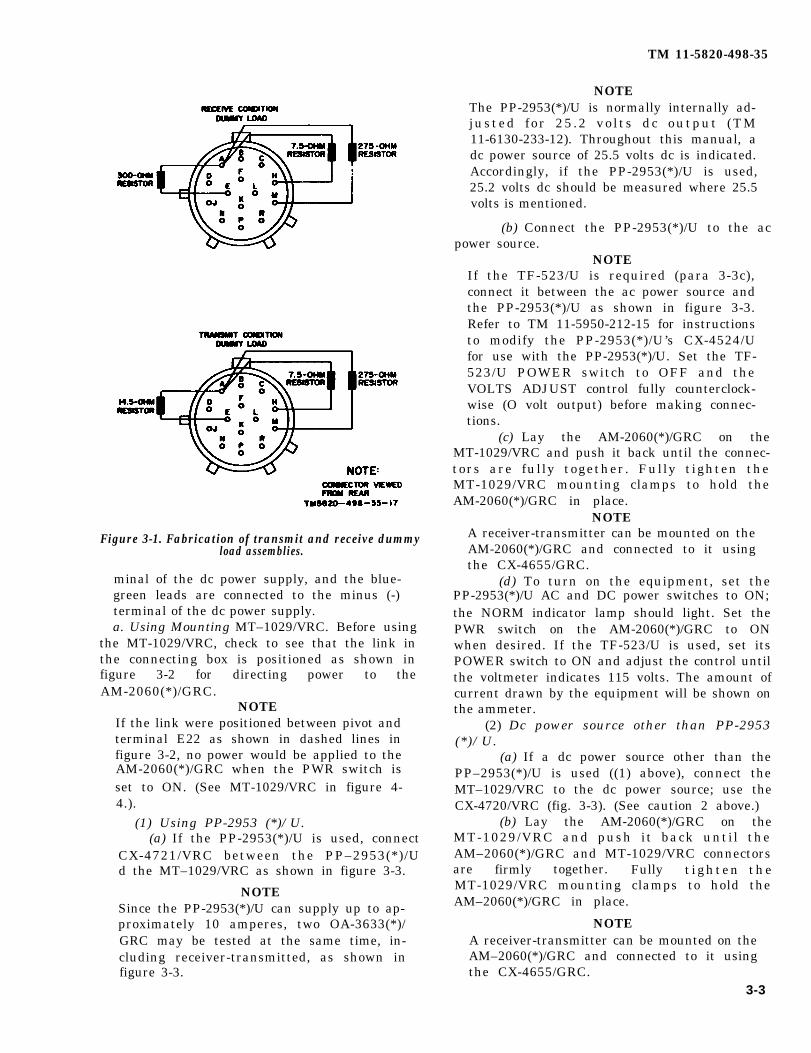
e. Transmit and Receive Dummy Load Assem-blies. Fabricate two dummy load assemblies to im-itate the transmit and receive states of the re-ceiver-transmitter that would be connected to the
3-2 Change 2
AM-2060(*)/GRC SET POWER connectorthrough the CX-4655/GRC.
(1) Remove the two connector plugs from theCX-4655/GR C (b above).
(2) Designate one of the connector plugs asthe transmit dummy load assembly, and correctthe load resistors (b above) as shown in figure3-1.
(3) Designate one of the connector plugs asthe receive dummy load assembly, and connectthe load resistors (b above) as shown figure 3-1.
3-4. Connecting Dc Power to AM-2060(*) /
There are two methods for connecting dc power tothe AM-2060(*)/GRC. One method is to use theMT-1029/VRC (a below): the other method is touse a fabricated power distribution box ( bbelow).
CAUTION 1Before making dc power connection makesure the dc power supply POWER switch andthe PWR switch on the AM-2060(*)/GRCare set to off.
CAUTION 2If the CX-4720/VRC power cable is used(a(2) and b(4) below), make sure the red-white leads are connected to plus (+) ter-
Publication
GRC
TM 11-5820-498-35
Figure 3-1. Fabrication of transmit and receive dummyload assemblies.
minal of the dc power supply, and the blue-green leads are connected to the minus (-)terminal of the dc power supply.a. Using Mounting MT–1029/VRC. Before using
the MT-1029/VRC, check to see that the link inthe connecting box is positioned as shown infigure 3-2 for directing power to theAM-2060(*)/GRC.
NOTEIf the link were positioned between pivot andterminal E22 as shown in dashed lines infigure 3-2, no power would be applied to theAM-2060(*)/GRC when the PWR switch isset to ON. (See MT-1029/VRC in figure 4-4.).
(1) Using PP-2953 (*)/U.(a) If the PP-2953(*)/U is used, connect
CX-4721/VRC between the PP–2953(*)/Ud the MT–1029/VRC as shown in figure 3-3.
NOTESince the PP-2953(*)/U can supply up to ap-proximately 10 amperes, two OA-3633(*)/GRC may be tested at the same time, in-cluding receiver-transmitted, as shown infigure 3-3.
NOTEThe PP-2953(*)/U is normally internally ad-justed for 25 .2 vo l ts dc output (TM11-6130-233-12). Throughout this manual, adc power source of 25.5 volts dc is indicated.Accordingly, if the PP-2953(*)/U is used,25.2 volts dc should be measured where 25.5volts is mentioned.
(b) Connect the PP-2953(*)/U to the acpower source.
NOTEIf the TF-523/U is required (para 3-3c),connect it between the ac power source andthe PP-2953(*)/U as shown in figure 3-3.Refer to TM 11-5950-212-15 for instructionsto modify the PP-2953(*)/U’s CX-4524/Ufor use with the PP-2953(*)/U. Set the TF-523/U POWER switch to OFF and theVOLTS ADJUST control fully counterclock-wise (O volt output) before making connec-tions.
(c) Lay the AM-2060(*)/GRC on theMT-1029/VRC and push it back until the connec-tors are fully together. Fully tighten theMT-1029/VRC mounting clamps to hold theAM-2060(*)/GRC in place.
NOTEA receiver-transmitter can be mounted on theAM-2060(*)/GRC and connected to it usingthe CX-4655/GRC.
(d) To turn on the equipment, set thePP-2953(*)/U AC and DC power switches to ON;the NORM indicator lamp should light. Set thePWR switch on the AM-2060(*)/GRC to ONwhen desired. If the TF-523/U is used, set itsPOWER switch to ON and adjust the control untilthe voltmeter indicates 115 volts. The amount ofcurrent drawn by the equipment will be shown onthe ammeter.
(2) Dc power source other than PP-2953(*)/U.
(a) If a dc power source other than thePP–2953(*)/U is used ((1) above), connect theMT–1029/VRC to the dc power source; use theCX-4720/VRC (fig. 3-3). (See caution 2 above.)
(b) Lay the AM-2060(*)/GRC on theMT-1029/VRC and push it back until theAM–2060(*)/GRC and MT-1029/VRC connectorsare firmly together. Fully t ighten theMT-1029/VRC mounting clamps to hold theAM–2060(*)/GRC in place.
NOTEA receiver-transmitter can be mounted on theAM–2060(*)/GRC and connected to it usingthe CX-4655/GRC.
3-3
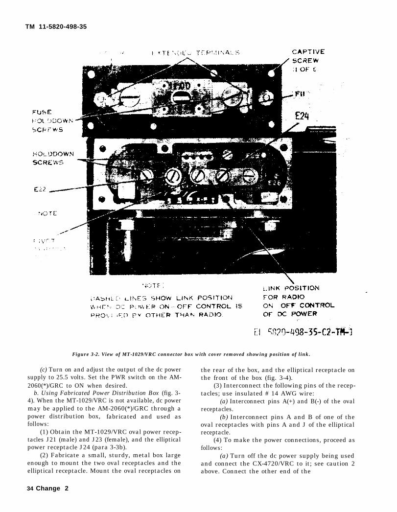
TM 11-5820-498-35
Figure 3-2. View of MT-1029/VRC connector box with cover removed showing position of link.
(c) Turn on and adjust the output of the dc powersupply to 25.5 volts. Set the PWR switch on the AM-2060(*)/GRC to ON when desired.
b. Using Fabricated Power Distribution Box (fig. 3-4). When the MT-1029/VRC is not available, dc powermay be applied to the AM-2060(*)/GRC through apower distribution box, fabricated and used asfollows:
(1) Obtain the MT-1029/VRC oval power recep-tacles J21 (male) and J23 (female), and the ellipticalpower receptacle J24 (para 3-3b).
(2) Fabricate a small, sturdy, metal box largeenough to mount the two oval receptacles and theelliptical receptacle. Mount the oval receptacles on
the rear of the box, and the elliptical receptacle onthe front of the box (fig. 3-4).
(3) Interconnect the following pins of the recep-tacles; use insulated # 14 AWG wire:
(a) Interconnect pins A(+) and B(-) of the ovalreceptacles.
(b) Interconnect pins A and B of one of theoval receptacles with pins A and J of the ellipticalreceptacle.
(4) To make the power connections, proceed asfollows:
(a) Turn off the dc power supply being usedand connect the CX-4720/VRC to it; see caution 2above. Connect the other end of the
34 Change 2

Figure 3-3. Connecting power to OA-3633/GRC using PP-2953(*)/U and TF-523/U.
CX-4720/VRC to the male receptacle on the power distribution box may be connected to anotherdistribution box (D, fig. 8-4). piece of equipment using the CX-4721/VRC.
(b) Connect the elliptical receptacle on the (d) Turn on and adjust the output of the dcpower distribution box to POWER INPUT recep- power supply to 25.5 volts. Set the PWR switch ontacle on the rear of the AM-2060(*)/GRC. the AM–2060(*)/GRC to ON when desired.
(c) The female receptacle on the power
Section II. OA-3633(*)/GRC, TROUBLESHOOTING PROCEDURES
3-5. Troubleshooting OA-3633(*)/GRCa. When the AM–2060(*)/GRC resistors R6, R7,
and R8 (fig. 3-18) are charred, there will be noaudio output from the AM–2060(*)/GRC tO thereceiver-transmitter. These charred resistors usu-ally indicate that the power cable in the vehicle(usually the CX-4720/VRC) in which theAM-2060(*)/GRC had been used, had been con-nected incorrectly to the vehicular battery. Thatis, the CX-4720/VRC negative leads (blue-green)had been connected to the battery positive termi-nal, and the positive leads (red-white) had beenconnected to the battery negative terminal. Toprevent incorrect battery connections, the follow-ing precautionary procedures are recommended:
(1) Mark the battery terminals of the vehicu-lar battery power cable so that the person that re-
places the cable leads to the battery knows thepositive power cable lead(s) and the negativepower cable lead(s). The battery negative termi-nal can be identified by the fact that it is smaller
than the positive battery terminal and it is con-nected to the vehicular chassis by a bonding strap.
(2) Install Suppressor, Electrical MX-7778/GRC in the battery distribution circuitof the vehicle. Installation procedures are pro-vided in TM 11–5195-223-15, which also coversmaintenance of the suppressor. T h e M X -7778/GRC protects the vehicle from circuitoverload (short circuit) in the radio (and inter-com) equipment and the radio (and intercom)equipment from electrical transient voltages inthe vehicle electrical system.
b. When trouble is suspected in the applicationof operating dc voltages to the receiver-transmit-ter that was used with the AM-2060(*)/GRC,check the AM–2060(*)/GRC output circuits byperforming measurements of the output voltagesand resistances at connector J2 (para 3–8, fig.3-6).
c. When trouble is suspected in the audio ampli-
3-5
TM 11-5820-498-35

TM 11-5820-498-35
Figure 3-4. Fabrication and connection of power distribution box.
3-6
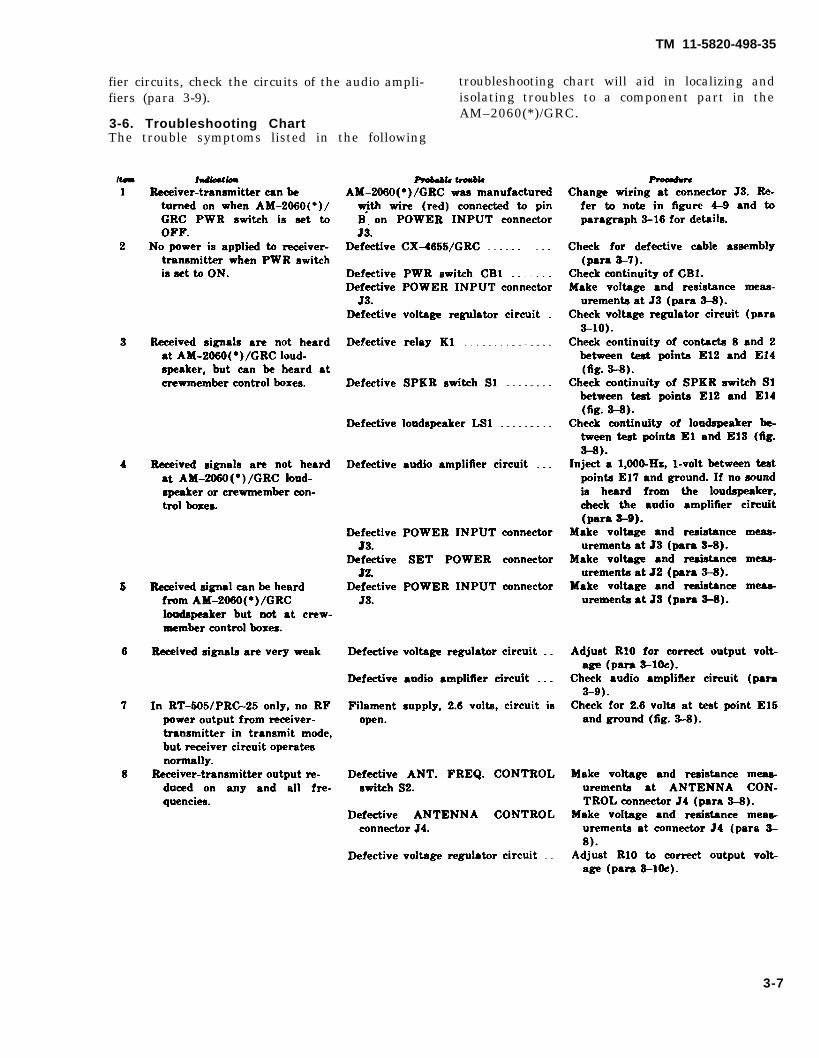
TM 11-5820-498-35
fier circuits, check the circuits of the audio ampli- troubleshooting chart will aid in localizing andfiers (para 3-9).
3-6. Troubleshooting ChartThe trouble symptoms listed in the following
isolating troubles to a component part in theAM–2060(*)/GRC.
3-7
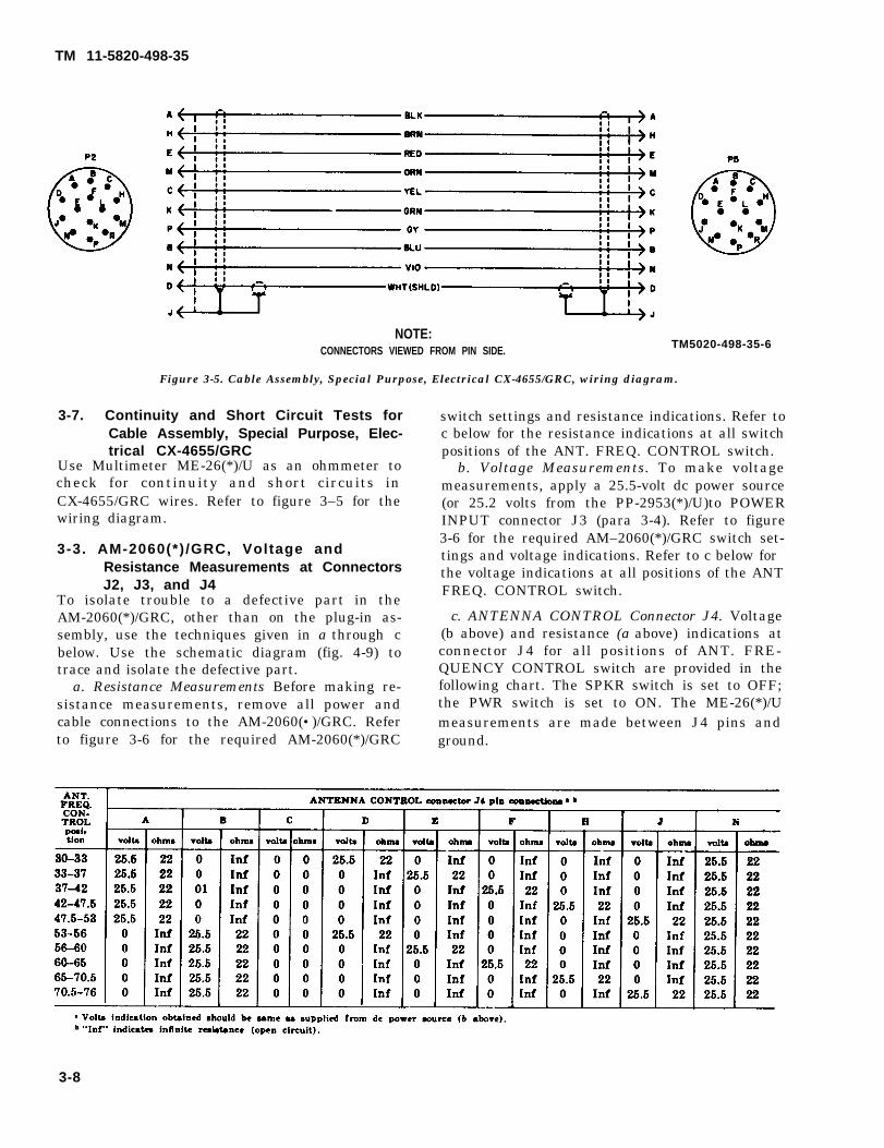
NOTE:CONNECTORS VIEWED FROM PIN SIDE. TM5020-498-35-6
Figure 3-5. Cable Assembly, Special Purpose, Electrical CX-4655/GRC, wiring diagram.
3-7. Continuity and Short Circuit Tests forCable Assembly, Special Purpose, Elec-trical CX-4655/GRC
Use Multimeter ME-26(*)/U as an ohmmeter tocheck for continuity and short circuits inCX-4655/GRC wires. Refer to figure 3–5 for thewiring diagram.
3-3. AM-2060(*) /GRC, Voltage andResistance Measurements at ConnectorsJ2, J3, and J4
To isolate trouble to a defective part in theAM-2060(*)/GRC, other than on the plug-in as-sembly, use the techniques given in a through cbelow. Use the schematic diagram (fig. 4-9) totrace and isolate the defective part.
a. Resistance Measurements Before making re-sistance measurements, remove all power andcable connections to the AM-2060(•)/GRC. Referto figure 3-6 for the required AM-2060(*)/GRC
switch settings and resistance indications. Refer toc below for the resistance indications at all switchpositions of the ANT. FREQ. CONTROL switch.
b. Voltage Measurements. To make voltagemeasurements, apply a 25.5-volt dc power source(or 25.2 volts from the PP-2953(*)/U)to POWERINPUT connector J3 (para 3-4). Refer to figure3-6 for the required AM–2060(*)/GRC switch set-tings and voltage indications. Refer to c below forthe voltage indications at all positions of the ANT FREQ. CONTROL switch.
c. ANTENNA CONTROL Connector J4. Voltage(b above) and resistance (a above) indications atconnector J4 for all positions of ANT. FRE-QUENCY CONTROL switch are provided in thefollowing chart. The SPKR switch is set to OFF;the PWR switch is set to ON. The ME-26(*)/Umeasurements are made between J4 pins andground.
3-8
TM 11-5820-498-35
TM 11-5820-496-35
3-9. AM-2060(*)/GRC, Isolating Troubles inAudio Amplifiers Q1 and Q2
When trouble has been localized to audio ampli-fiers Q1 and Q2, use the following proceduresto isolate the defective part in the circuit.
a. The following equipment is required:(1) A 25.5-volt dc power source (or 25.2-volt
output of Power Supply PP–2953(*)/U).(2) Generator, Signal AN/URM-127.(3) Voltmeter, Electronic ME-30(*)/U.(4) Receive dummy load assembly (para
3-3e, fig. 3-1).b. Remove the access plate (fig, 3–10) from the
top of the AM–2060(*)/GRC to gain access to thetest points El through E22 on the plug-in assem-bly (fig. 3-11 and 3-15).
c. Connect the receive dummy load assembly toSET POWER connector J2 (fig. 3-7).
d. Connect the dc power source (a(1) above) topins A (chassis ground) and J of POWER INPUTconnector J3 (fig. 3–7).
e. Set the PWR and SPKR switches to ON.f. Apply a 1-kHz, 1-volt signal from the
AN/URM-127 with its adapter UG–514/U to pinsA (chassis ground) and B of SET POWERconnector J2 (fig. 3-7).
g. When the ME–30(*)/U is connected betweenpins E1 and E14 of the plug-in-assembly (fig.3-9),it should indicate 4.5 ± 0.10 volts ac. If theME-30(*)/U indication is not approximately 4.5volts ac, make voltage and resistance measurements of the audio amplifier circuit and also thevoltage regulator circuit.
(1) To make the voltage measurements, leavethe dc power connected to connector J3 (d above)and make the voltage measurements at the pins ofthe plug-in assembly (fig. 3–9).
(2) TO make the resistance measurements,remove the dc power from connector J3, and makethe resistance measurements at the pins of theplug-in assembly.
(3) Refer to paragraph 3-11 for dc resist-ance of transformers and coils involved in thecircuits.
3-10. AM-2060(*)/GRC, Adjustment of R10,and Isolating Troubles in Voltage Regu-lator Circuits Q3 and Q4
When trouble has been localized to voltage regula-tors Q3 and Q4, use the following procedures toisolate the defective part in the circuit.
a. Equipment Required.(1) A 25.5-volt dc power source (or 25.2-
volt output of Power Supply PP-2953(*)/U).(2) Multimeter ME-26(*)/U.
(3) Transmit dummy load assembly (para3-3e, fig. 3-1).
b. Test Setup.(1) Remove the access plate (fig. 3-10)
from the top of the AM–2060(*)/GRC to gain ac-cess to the test points El through E22 on theplug-in assembly (fig. 3-9).
(2) Connect the transmit dummy load as-sembly to SET POWER connector J2 (fig. 3–8).
(3) Connect the dc power source (a(1)above) to pins A (chassis ground and J ofPOWER INPUT connector J3 (fig. 3-8).
(4) Set the PWR switch to ON.c. Output Voltage Adjustments, R1O.
(1) Perform the test setup given in b above.(2) Connect the ME-26(*)/U, arranged as a
dc voltmeter, between pins E (positive) and A(chassis ground) (14.5-ohm load resistor) ofSET POWER connector J2 (fig. 3–8).
(3) Loosen the locknut holding the adjust-ment screw of R10 (fig. 3–11).
NOTEIf the locknut cannot be easily loosened, usea drop of penetrating oil on the threads andallow it to penetrate before trying to loosenthe locknut.
(4) Adjust R10 adjustment screw for an in-dication of +13 volts on the ME-26(*)/U. Fin-gertighten the locknut holding the control.
d. Isolating Troubles in Voltage Regulator Cir-cuit Q3 and Q4.
(1) Perform the test setup and adjustmentprocedures given in b and c above before proceed-ing.
(2) Measure the voltage drop across refer-ence diode CR1 by placing the ME-26(*)/U nega-tive lead on test point E1 and the positive testlead on test point E6 (fig. 3-9). The ME-26(*)/Ushould indicate approximately 6.8 volts dc.
(3) Measure the voltage drop across ref-erence diode CR2 by placing the ME–26(*)/Unegative lead on test point E3 and the positivetest lead on test point E4. The ME–26(*)/Ushould indicate approximately 6.8 volts dc.
(4) If the voltage indication obtained acrossCR1 and CR2 is still not within limits, make volt-age and resistance measurements of the voltageregulator circuits to determine the defective part.
3-11. Dc Resistance of Transformers and CoilsThe dc resistance of the transformer windingsand the relay coil on the plug-in assembly ofthe AM-2060(*)/GRC are listed in the followingchart.
3-9
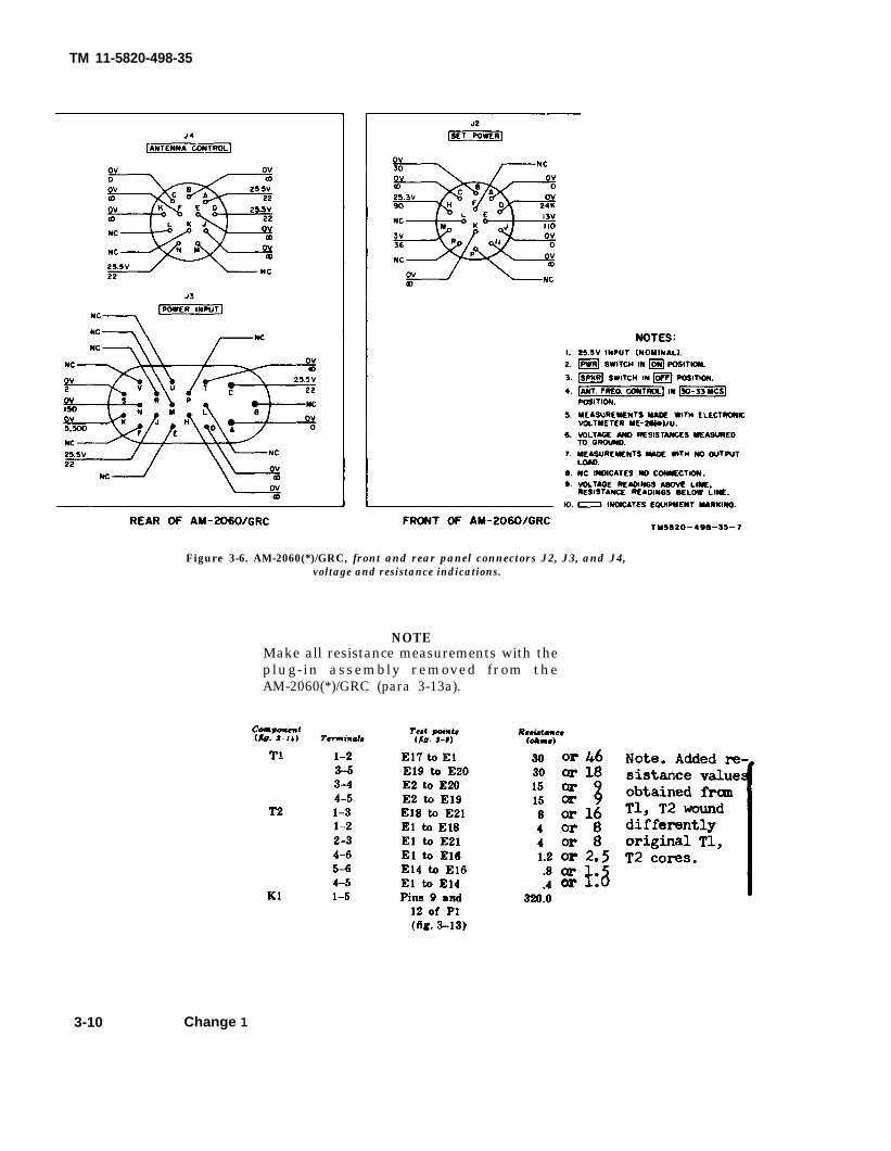
Figure 3-6. AM-2060(*)/GRC, front and rear panel connectors J2, J3, and J4,voltage and resistance indications.
NOTEMake all resistance measurements with theplug-in assembly removed from theAM-2060(*)/GRC (para 3-13a).
3-10 Change 1
TM 11-5820-498-35

3-11
TM 11-5820-498-35
Figure 3-7. Test setup for isolating trouble in audio amplifiers Q1 and Q2.
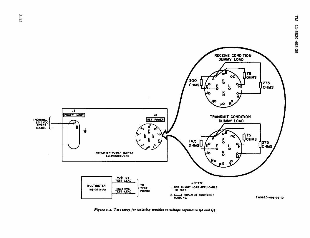
3-1
2
TM
11-5820-498-35

TM 11-5820-498-35
Section lll. OA-3633(*)GRC, PARTS REMOVAL ANDREPLACEMENT PROCEDURES
3-12. General a. Most of the parts of the AM-2060(*)/GRC
may be easily reached, and replacedwithin the equipment without special procedures.
Paragraphs 3-13 through 3-15 contain removaland replacement procedure for those parts ofthe AM-2060(*)/GRC which are not obvious orwhich require precautionary procedures.
b. No special tools are required, except that inremoving transistors and diodes, use a pencil-typesoldering iron with a 25-watt maximum capacity.With a pair of long-nose pliers, grasp the lead be-tween the transistor or diode and the solder con-nection to dissipate the soldering iron heat.
3-13. AM-2060(*)/GRC, Plug-In Assembly,Removal and Replacement
The plug-in assembly (fig. 3-11) is removed forperforming repairs on it (fig. 3-13 and 3-14),and to gain access to parts under it (fig. 3-12).Before proceeding, remove all cable connectionsto the AM–2060(*)/GRC and remove the accessplate from the top of the equipment (fig.3-10).
a. Plug-In Assembly Removal and Replace-ment.
(1) Removal.(a) Remove the four captive screws that
hold the plug-in assembly to the chassis (fig.3-11).
(b) Grasp the plug-in assembly and pullthe assembly straight up and out of the equip-ment.
(2) Replacement.(a) Insert the plug-in assembly so that
the plug on the bottom of the assembly mateswith the receptacle J1 on the bottom of theAM-2060-(*)/GRC (fig. 3-12).
(b) Tighten the four captive screws onthe plug-in assembly (fig. 3-11). Make sure thatthe plug-in assembly is not loose.
(c) Replace the access plate on top of theAM-2060(*)/GRC.
b. Plug-In Assembly Printed Circuit Board,Removal and Replacement. Use the followingprocedures to remove and replace the printed cir-cuit board of the plug-in assembly.
(1) Removal.(a) Remove the plug-in assembly (a(1)
above).(b) Unsolder the wires attached to test
points E1 through E17 (fig. 3-9) on the top of
the plug-in assembly. Tag each wire with theidentification of the terminal from which it wasremoved.
(c) Remove the screws, nuts, and spacersthat secure the printed circuit board to the plug-in assembly.
(2) Replacement (fig. 3-15).(a) Insert a screw and washer through
each of the four mounting holes of the printedcircuit board.
(b) Place a spacer over each of the fourscrews.
(c) Align the mounting holes of the plug-in assembly with the screws in the printed circuitboard and insert the screws through the mount-ing holes.
(d) Place a washer and nut on each of thefour screws and tighten the nut securely.
(e) Solder the wires to test points E1through E17 (fig. 3-9). Check each wire tag toinsure the correct replacement.
(f) Replace the plug-in assembly in theAM–2060(*)/GRC (a(2) above).
3-14. AM-2060(*)/GRC, Loudspeaker LS1Removal and Replacement
The loudspeaker is removed from the front panelfor testing and replacement, or to gain acc'ess tothe area behind it. Before proceeding, remove allcable connections.
a. Removal.(1) Remove the four mounting screws that
attach the loudspeaker cover with the loud-speaker a t t a c h e d t o t h e f r o n t of theAM–2060(*)/GRC. Place the nylon strap at-tached to the SET POWER connector dust capclear of the loudspeaker area.
(2) Grasp the front of the loudspeakercover and pull the loudspeaker cover from theloudspeaker by holding LS1 firmly and snappingthe cover off.
WARNINGWhen soldering and unsoldering the voicecoil leads, be careful to prevent the glass por-tion of the terminals from cracking due toexcessive heat. Grasp the terminal lead witha pair of pliers, between the glass bead andthe eye of the terminals, before applyingheat.
(3) Unsolder the leads that connect the voicecoil of LS1 to the feedthrough terminals at the
3-13
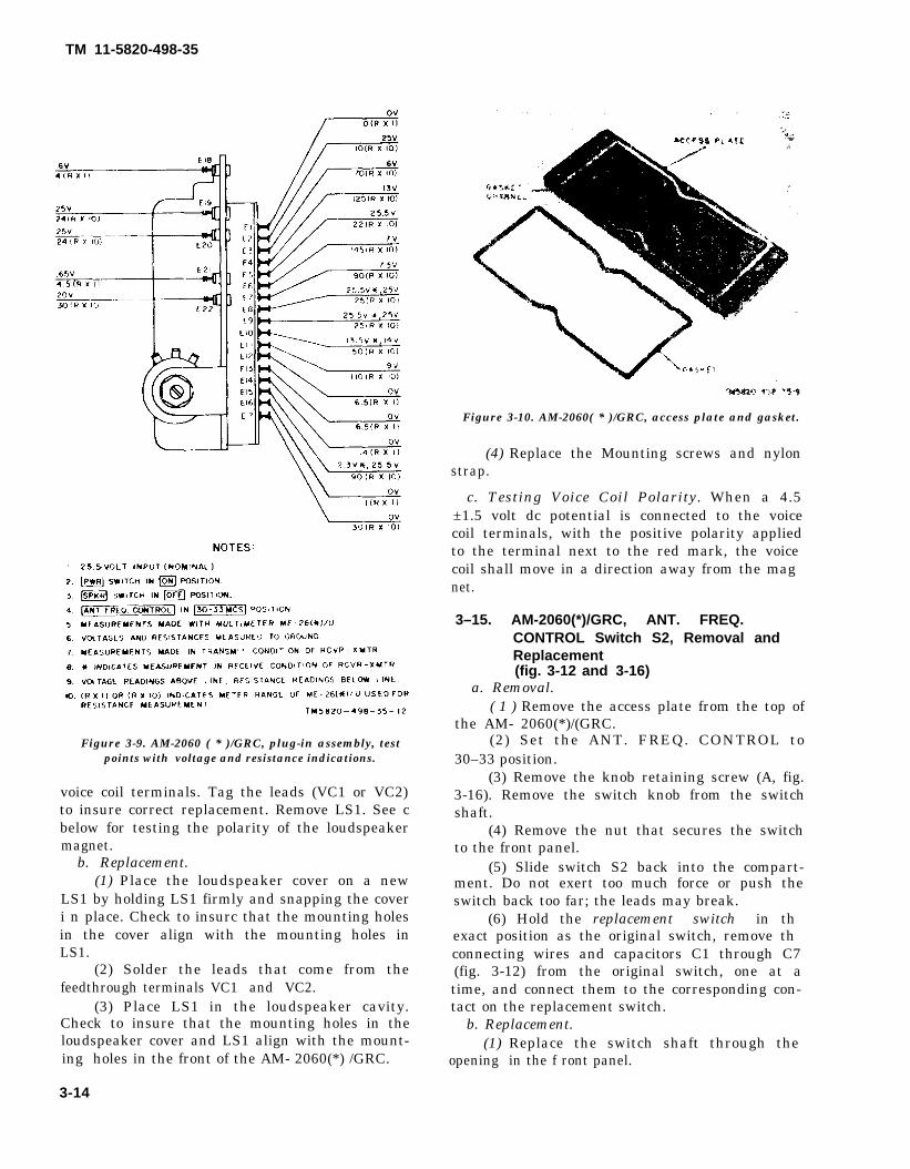
TM 11-5820-498-35
Figure 3-9. AM-2060 ( * )/GRC, plug-in assembly, testpoints with voltage and resistance indications.
voice coil terminals. Tag the leads (VC1 or VC2)to insure correct replacement. Remove LS1. See cbelow for testing the polarity of the loudspeakermagnet.
b. Replacement.(1) Place the loudspeaker cover on a new
LS1 by holding LS1 firmly and snapping the coveri n place. Check to insurc that the mounting holesin the cover align with the mounting holes inLS1.
(2) Solder the leads that come from thefeedthrough terminals VC1 and VC2.
(3) Place LS1 in the loudspeaker cavity.Check to insure that the mounting holes in theloudspeaker cover and LS1 align with the mount-ing holes in the front of the AM- 2060(*) /GRC.
3-14
Figure 3-10. AM-2060( * )/GRC, access plate and gasket.
(4) Replace the Mounting screws and nylonstrap.
c. Testing Voice Coil Polarity. When a 4.5±1.5 volt dc potential is connected to the voicecoil terminals, with the positive polarity appliedto the terminal next to the red mark, the voicecoil shall move in a direction away from the magnet.
3–15. AM-2060(*)/GRC, ANT. FREQ.CONTROL Switch S2, Removal andReplacement(fig. 3-12 and 3-16)
a. Removal.( 1 ) Remove the access plate from the top of
the AM- 2060(*)/(GRC.(2) Set the ANT. FREQ. CONTROL to
30–33 position.(3) Remove the knob retaining screw (A, fig.
3-16). Remove the switch knob from the switchshaft.
(4) Remove the nut that secures the switchto the front panel.
(5) Slide switch S2 back into the compart-ment. Do not exert too much force or push theswitch back too far; the leads may break.
(6) Hold the replacement switch in thexact position as the original switch, remove thconnecting wires and capacitors C1 through C7(fig. 3-12) from the original switch, one at atime, and connect them to the corresponding con-tact on the replacement switch.
b. Replacement.(1) Replace the switch shaft through the
opening in the f ront panel.

TM 11-5820-498-35
Figure 3-11. AM-2060(*)IGRC, top view with plug-in assembly in place.
Figure 3–12. AM–2060(*)/GRC, top view with plug-in assembly removed.
3-15
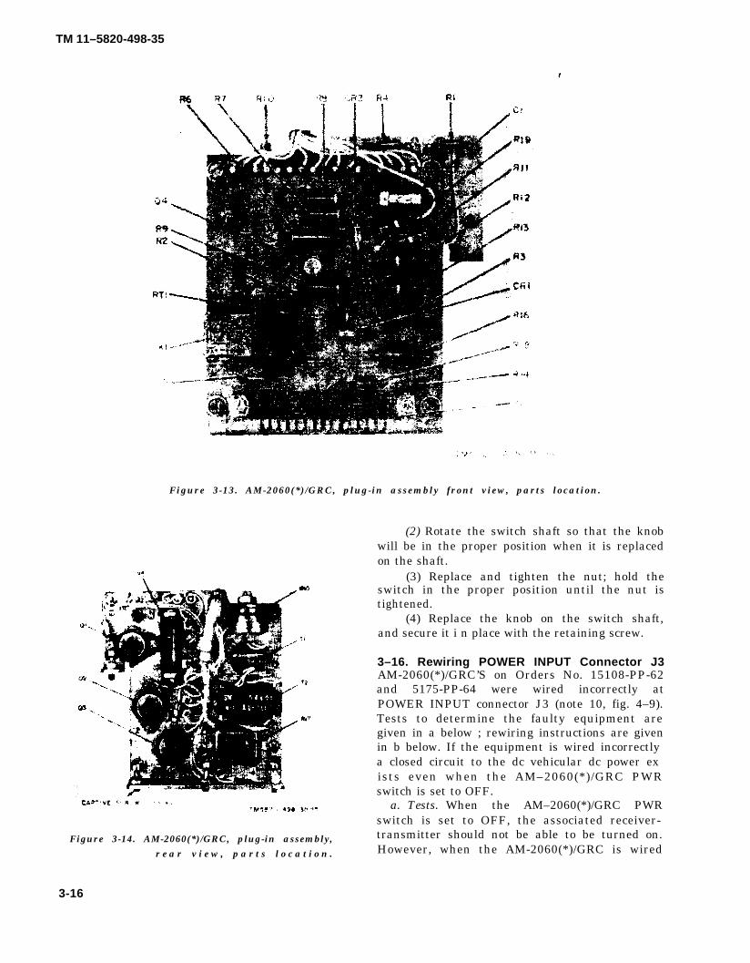
TM 11–5820-498-35
(2) Rotate the switch shaft so that the knobwill be in the proper position when it is replacedon the shaft.
(3) Replace and tighten the nut; hold theswitch in the proper position until the nut istightened.
(4) Replace the knob on the switch shaft,and secure it i n place with the retaining screw.
3–16. Rewiring POWER INPUT Connector J3AM-2060(*)/GRC’S on Orders No. 15108-PP-62and 5175-PP-64 were wired incorrectly atPOWER INPUT connector J3 (note 10, fig. 4–9).Tests to determine the faulty equipment aregiven in a below ; rewiring instructions are givenin b below. If the equipment is wired incorrectlya closed circuit to the dc vehicular dc power exists even when the AM–2060(*)/GRC PWRswitch is set to OFF.
a. Tests. When the AM–2060(*)/GRC PWRswitch is set to OFF, the associated receiver-transmitter should not be able to be turned on.However, when the AM-2060(*)/GRC is wired
3-16
Figure 3-13. AM-2060(*)/GRC, plug-in assembly front view, parts location.
Figure 3-14. AM-2060(*)/GRC, plug-in assembly, r e a r v i e w , p a r t s l o c a t i o n .
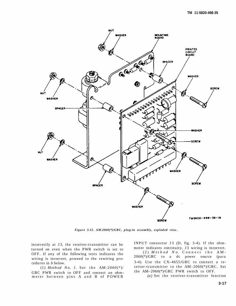
Figure 3-15. AM-2060(*)/GRC, plug-in assembly, exploded view.
incorrectly at J3, the receiver-transmitter can beturned on even when the PWR switch is set toOFF. If any of the following tests indicates thewiring is incorrect, proceed to the rewiring pro-cedures in b below.
(1) Method No. 1. Set the AM-2060(*)/GRC PWR switch to OFF and connect an ohm-meter between pins A and B of POWER
INPUT connector J3 (D, fig. 3-4). If the ohm-meter indicates continuity, J3 wiring is incorrect.
(2 ) M e t h o d N o . C o n n e c t t h e A M -2060(*)/GRC to a dc power source (para3-4). Use the CX–4655/GRC to connect a re-ceiver-transmitter to the AM–2060(*)/GRC. Setthe AM–2060(*)/GRC PWR switch to OFF.
(a) Set the receiver-transmitter function
3-17
TM 11-5820-498-35
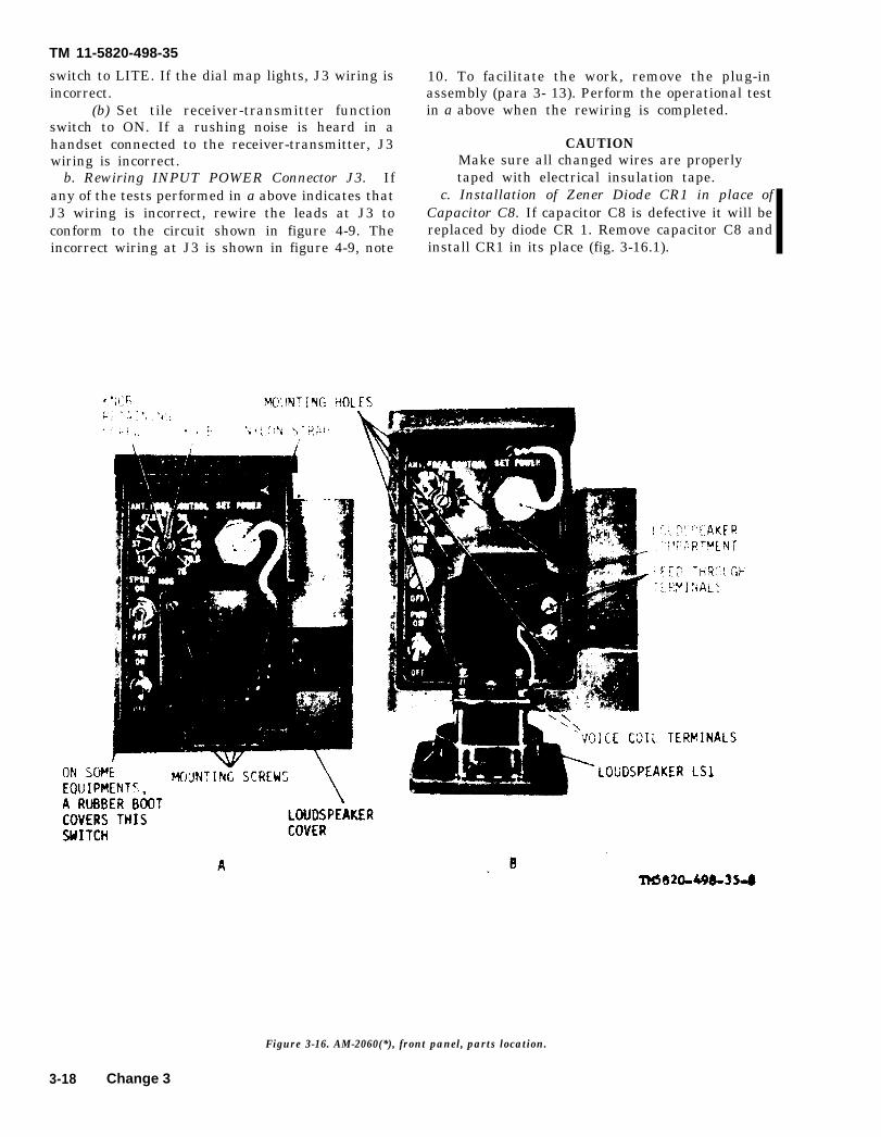
TM 11-5820-498-35
switch to LITE. If the dial map lights, J3 wiring isincorrect.
(b) Set tile receiver-transmitter functionswitch to ON. If a rushing noise is heard in ahandset connected to the receiver-transmitter, J3wiring is incorrect.
b. Rewiring INPUT POWER Connector J3. Ifany of the tests performed in a above indicates thatJ3 wiring is incorrect, rewire the leads at J3 toconform to the circuit shown in figure 4-9. Theincorrect wiring at J3 is shown in figure 4-9, note
10. To facilitate the work, remove the plug-inassembly (para 3- 13). Perform the operational testin a above when the rewiring is completed.
CAUTIONMake sure all changed wires are properlytaped with electrical insulation tape.
c. Installation of Zener Diode CR1 in place ofCapacitor C8. If capacitor C8 is defective it will bereplaced by diode CR 1. Remove capacitor C8 andinstall CR1 in its place (fig. 3-16.1).
Figure 3-16. AM-2060(*), front panel, parts location.
3-18 Change 3
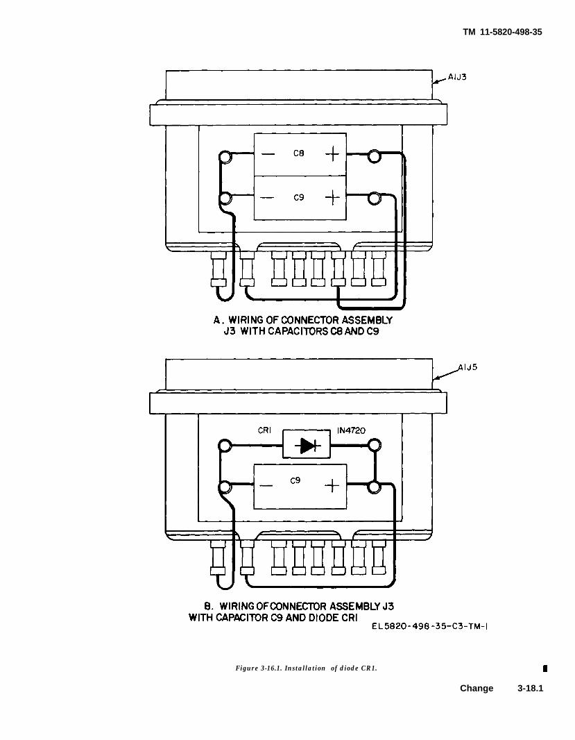
Figure 3-16.1. Installation of diode CR1.
TM 11-5820-498-35
Change 3-18.1
TM 11-5820-498-35
Section IV. OA-3633(*)/GRC, TESTING PROCEDURES
3-17. General 3-21 and 3-22). The CX-4655/GRC test proceduresBefore a repaired AM-2060(*)/GRC is returned to are given in paragraph 3-23.
the using organization, or to. stock, it must betested for acceptable performance. The AM- 3-18. Physical Tests and Inspection
2060(*)/GRC performance checks include physical a. Test Equipment and Material. None.tests (para 3-18), and testing the continuity of b. Test Connection and Conditions. Remove thecircuits (para 3-19), dc output voltages (para 3-20), access plate from the top of the AM-2060(*)/GRC.and the audiofrequency amplifier circuits (para
3-18.2 Change 3
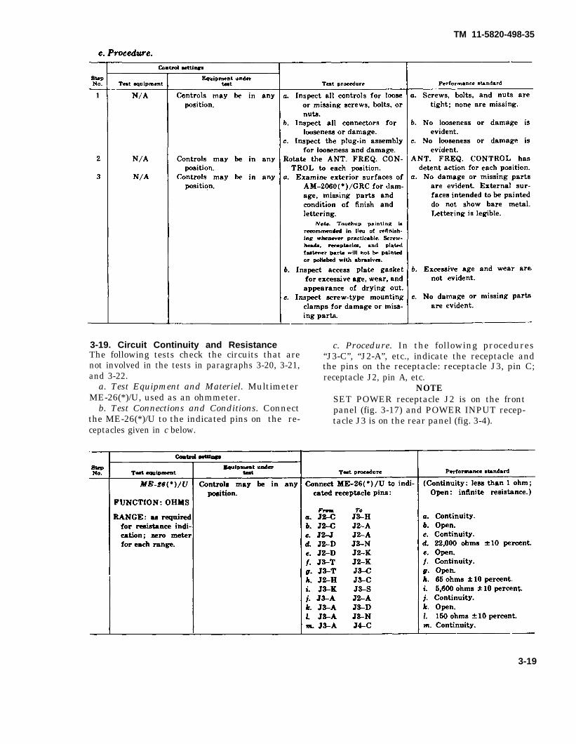
TM 11-5820-498-35
3-19. Circuit Continuity and Resistance c. Procedure. In the following proceduresThe following tests check the circuits that are “J3-C”, “J2-A”, etc., indicate the receptacle andnot involved in the tests in paragraphs 3-20, 3-21, the pins on the receptacle: receptacle J3, pin C;and 3-22. receptacle J2, pin A, etc.
a. Test Equipment and Materiel. Multimeter NOTEME-26(*)/U, used as an ohmmeter. SET POWER receptacle J2 is on the front
b. Test Connections and Conditions. Connect panel (fig. 3-17) and POWER INPUT recep-the ME-26(*)/U to the indicated pins on the re- tacle J3 is on the rear panel (fig. 3-4).ceptacles given in c below.
3-19
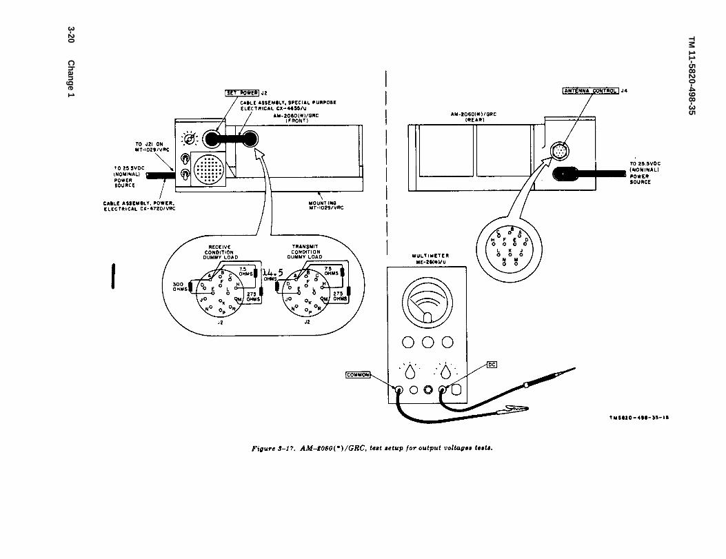
TM
11-5820-498-35
3-20 Change 1
TM 11-5820-498-35
3-20. Output Voltages Testsa. Test Equipment and Materials.
(1) Multimeter ME-26(*)/U.(2) Mounting MT-1029/VRC.(3) Power Supply PP-2953(*)/U, or equal.(4) Cable Assembly, Power, Electrical CX-4720/VRC.(5) Transmit and receive dummy load assemblies.
b. Test Connections and Conditions. Connect the equipment as shown in figure 3-17. Turn the equip-men on, and allow it to warm up for 5 minutes before proceeding.
Change 1 3-21
c. Procedure.
TM 11-5820-4984-35
StepNo.
Control settings
Test equipment
RANGE switch: 100V(zero meter)
Equipment undertestTest proccedure
b. Set the AM-2060(*)/GRCANT. FREQ. CONTROL30-33 MCS. Connect theME-26(*)/U DC probeto pins A, D, and N ofthe receptacle.
c. Set the AM–2060(*)/GRCANT. FREQ. CONTROLto 33-37 MCS. Connectthe ME-26(*)/U DCprobe to pins A and Eof the receptacle.
d. Set the AM-2060(*)/GRCANT. FREQ. CONTROLto 37-42 MCS. Connectthe ME-26(*)/U DCprobe to pins A and Fof the receptacle.
e. Set the AM-2060(*)/GRCANT. FREQ. CONTROLto 42-47.5 MCS. Connectthe ME-26(*)/U DCprobe to pins A and Hof the receptacle.
f. Set the AM-2060(*)/GRCANT. FREQ. CONTROLto 47.5–53 MCS. Connectthe ME-26(*) /U probeto pins A and J of thereceptacle.
g. Set the AM-2060(*)/GRCANT. FREQ. CONTROLto 53-56 MCS. Connectthe ME-26(*)/U DCprobe to pins B and Dof the receptacle.
h. Set the AM-2060(*)/GRC
i.
j.
k.
ANT. FREQ. CONTROLto 56-60 MCS. Connectthe ME-26(*)/U DCprobe to pins B and E ofthe receptacle.
Set the AM-2060(*)/GRCANT. FREQ. CONTROLto 60-65. Connect theME-26(*)/U DC probeto pins B and F of thereceptacle.
Set the AM-2060(*)/GRCANT. FREQ. CONTROLto 65-70.5 MCS. Connectthe ME–26(*)/U DCprobe to pins B and H ofthe receptacle.
Set the AM-2060(*)/GRCANT. FREQ. CONTROLto 70.5–76 MCS. Connectthe ME-26(*)/U DCprobe to pins B and Jof the receptacle.
Performance standard
b. 25.5 volts on pins A, D, andN.
c. 25.5 volts on pins A and E.
d. 25.5 volts on pins A and F.
e. 25.5 volts on pins A and H.
f. 25.5 volts on pins A and J.
g. 26.5 volts on pins B and D.
h. 25.5 volts on pins B and E.
i. 25.5 volts on pins B and F.
j. 25.5 volts on pins B and H.
k. 25.5 volts on pins B and J.
3-22

TM 11-5820-498-35
3-21. Audio Amplifier Gain and Frequency Response Testsa. Test Equipment and Materials.
(1) Generator, Signal AN/URM--127. (7) Resistor, carbon: 130 ohms(2) Voltmeter, Electronic ME-30(*)/U.(3) Mounting MT-1029/VRC.
±10%, 5 watt 8.
(4) Power Supply PP-2953(*)/U, or equal.(6) Cable Assembly, Power, Electrical CX-4720/VRC.(6) Receive dummy load assembly (para 3-3e, fig. 3-1).
b. Test Connection and Conditions. Remove the access plate from the top of the AM-2060(*)/GRC andconnect the equipment as shown in figure 3-18. Turn on the equipment and allow it to warm up for 5minutes before preceding.
C. Procedure.
Change 2 3 -23
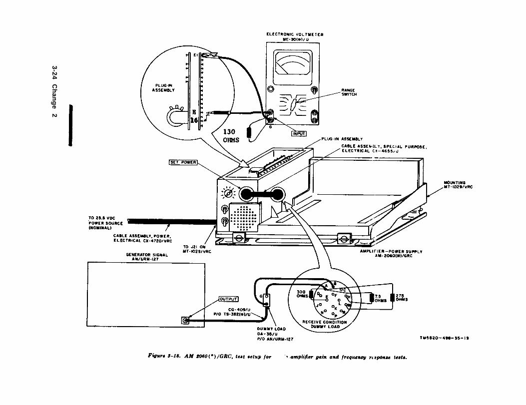
3-24 C
han
ge
2
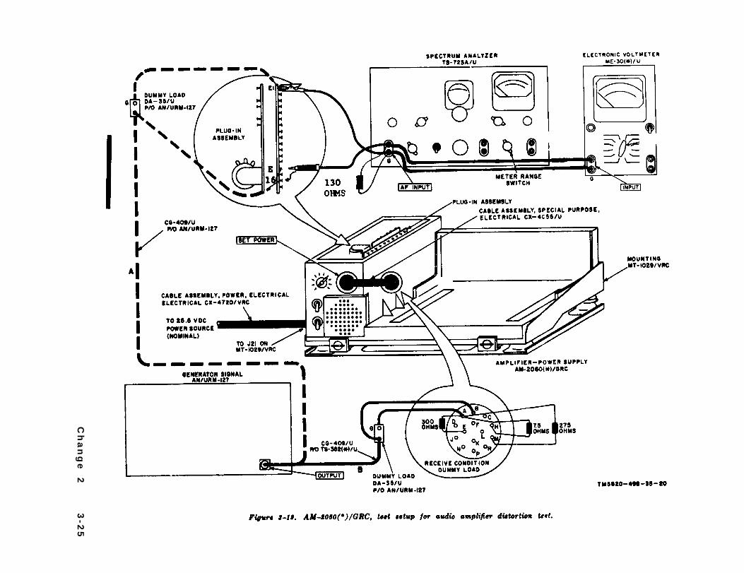
Ch
an
ge
2
3-2
5
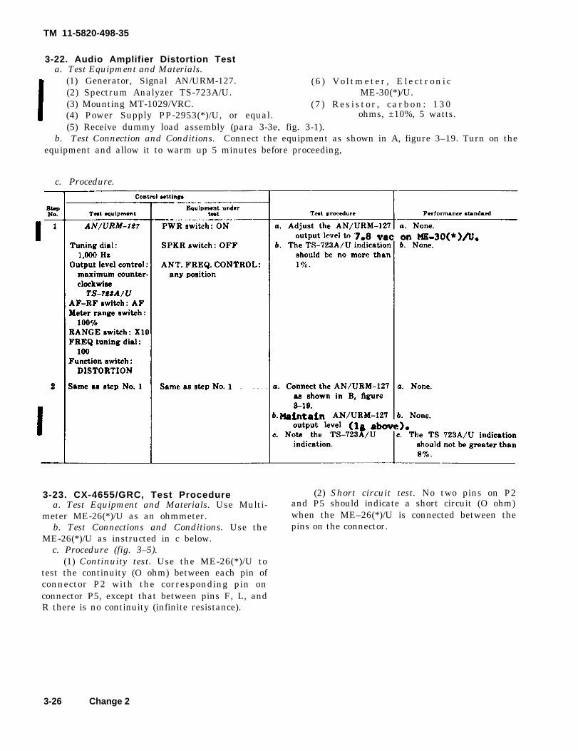
TM 11-5820-498-35
3-22. Audio Amplifier Distortion Testa. Test Equipment and Materials.
(1) Generator, Signal AN/URM-127. (6 ) Vo l tmeter , Electronic(2) Spectrum Analyzer TS-723A/U. ME-30(*)/U.(3) Mounting MT-1029/VRC. (7 ) Res is tor , carbon: 130(4) Power Supply PP-2953(*)/U, or equal. ohms, ±10%, 5 watts.(5) Receive dummy load assembly (para 3-3e, fig. 3-1).
b. Test Connection and Conditions. Connect the equipment as shown in A, figure 3–19. Turn on theequipment and allow it to warm up 5 minutes before proceeding,
c. Procedure.
3-23. CX-4655/GRC, Test Procedure (2) Short circuit test. No two pins on P2a. Test Equipment and Materials. Use Multi- and P5 should indicate a short circuit (O ohm)
meter ME-26(*)/U as an ohmmeter. when the ME–26(*)/U is connected between theb. Test Connections and Conditions. Use the pins on the connector.
ME-26(*)/U as instructed in c below.c. Procedure (fig. 3–5).
(1) Continuity test. Use the ME-26(*)/U totest the continuity (O ohm) between each pin ofconnector P2 with the corresponding pin onconnector P5, except that between pins F, L, andR there is no continuity (infinite resistance).
3-26 Change 2
TM 11-5820-498-35
3-23.1. Circuit Breaker Test of PWR Switcha. Teat Equipment and Materiels.
(1) Mounting MT-1029/VRC.(2) Power Supply PP-1104/G.(3) Cable Assembly, Power, Electrical CX-
4020/VRC.b. Test Connection and Conditions. Turn off the
PP-1104/G and set its OUTPUT control fully coun-terclockwise (minimum output). Connect the PP-1104/G through the CX-4720/VRC to the MT-1029/VRC and AM-2060(*)/GRC (fig. 3-19). Removethe access plate from the top of the AM-2060(*)/GRCand connect a jumper between test point E5 (fig. 3-9)and the chassis.
c. Procedure.(1) Adjust the PP-1104/G OUTPUT control clock-
wise until the D.C. AMPERE meter indicates 4 am-peres. The AM-2060(*)/GRC PWR circuit breaker
shall not have tripped.(2) Continue to rotate the OUTPUT control
clockwise until the D.C. AMPERE meter indicates 6amperes. The AM-2060(*)/GRC PWR circuit breakershall have tripped before 6 ampere indication isreached.
NOTEThe magnetic circuit breaker required upto 1 ampere beyond its Specificationrequirement because of its proximity tothe loudspeaker magnet.
(3) Turn off the equipment and remove thejumper connection to teat point E5.
3-24. Summary of Test DataPersonnel may find it convenient to arrange achecklist of the test performance standards given inparagraphs 3-19 through 3-32.1 similar to the onegiven below.
Change 2 3-27
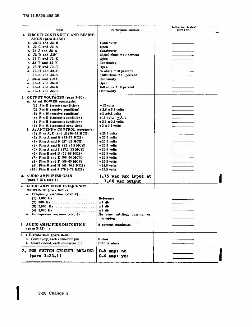
TM 11-5820-498-35
3-28 Change 2
TM 11-5820-498-35
CHAPTER 4DEPOT OVERHAUL STANDARDS
4-1. Applicability of Depot OverhaulStandards
The tests on repaired equipment are designed to mea-sure the performance capability of the equipment.Equipment that is returned to stock should meet thestandards given in the tests.
NOTEThe depot overhaul test procedures (DOS)should not be used to test the performanceof new equipment; that is, equipment thathas not been repaired or rebuilt. Suchequipment should be tested for conformancewith the electrical and operational testscited in the Military Specification underwhich the equipment was manufactured in-cluding all waivers and/or changes to thespecification that were imposed upon orgranted to the particular manufacturer ofthe equipment. For such information, ad-dress correspondence to: Commander, USArmy Communications-Electronics Com-mand, ATTN:DRSEL-ME-MQ, Fort Mon-mouth, NJ 07703.Following are production specifications ap-plicable to the radio equipment covered inthis manual:1. Amplifier-Power Supply GroupOA-3633(*)/GRC: Military SpecificationMIL-A-55147B(EL).
ComponentAmplifier-Power Supply Group . . . . . . . . . . . . . . . . . . . . . . . . . . . . . . . . . . Paragraphs 3-18 through
OA-3633(*)/GRC. 3-24 of this publication.
2. Antenna AS-1729/VRC: Military Speci-fication MIL-A-55288B(EL).3. Radio Set AN/PRC-25, IncludingRece iver -Transmitter , RadioRT-505/PRC-25: Military SpecificationMIL-R-55137C(EL).4. Radio Set AN/PRC-77, IncludingRece iver -Transmitter , RadioRT-841/PRC-77: Military Specification,MIL-R-55499B(EL).
4-2. Applicable Referencesa. Repair Standards. Applicable procedures of de-
pots performing tests and general standards for re-paired electronic equipment given in TB SIG 355-1, TBSIG 355-2, and TB SIG 355-3 form a part of the requirements for testing the components of the radio setscovered by this manual.
b. Modification Work Orders. Perform all modi-fication work orders (MWO’s) applicable to the equip-ment before making tests specified. DA Pam 310-7 listscurrent MWO’s.
4 - 3 . D e p o t O v e r h a u l S t a n d a r d sProcedures
Refer to the following publications for the depot over-haul standards for the indicated equipment which arepart of Radio Sets AN/VRC-53, AN/VRC-64, AN/GRC-125, and AN/GRC-160.
Publication
Radio Set AN/PRC-25, including . . . . . . . . . . . . . . . . . . . . . . . . . . . . . . . . . . . . . TM 11-5820-398-35.Receiver-Transmitter, RadioRT-505/PRC-25.
Radio Set AN/PRC-77 including . . . . . . . . . . . . . . . . . . . . . . . . . . . . . . . . . . . . . . TM 11-5820-667-35.Receiver-Transmitter, RadioRT-841/PRC-77.
Antenna AS-1729/VRC . . . . . . . . . . . . . . . . . . . . . . . . . . . . . . . . . . . . . . . . . . . . . . TM 11-5985-262-15.
Change 4 4-1/(4-2 blank)

TM 11-5820-498-35
APPENDIX AREFERENCES
CTA 50-970DA Pam 310-4SB 11-131TB SIG 355-1TB SIG 355-2TB SIG 355-3TM 11-5820-398-12
TM 11-5820-398-35TM 11-5820-398-20P
TM 11-5820-398-34P
TM 11-5820-401-10-1
TM
TM
11-5820-401-102
11-5820-401-12
TM 11-5820-401-20P
TM 11-5820-401-30-4
Expendable Items (Except: Medical, Class V, Repair Parts and Heraldic Items).Index of Technical Publications.Vehicular Radio Sets and Authorized Installations.Depot Inspection Standard for Repaired Signal Equipment.Depot Inspection Standard for Refinishing Repaired Signal Equipment.Depot Inspection Standard for Moisture and Fungus Resistance Treatment.Operator’s and organizational maintenance manual including repair parts and special
tools lists: Radio set AN/PRC-25 (NSN 5820-00-857-0759) (including receiver-trans-mitter, radio, RT-505/PRC-25) (NSN 5820-00-857-0934) (Reprinted w/basic incl ch 1-5).
Field and depot maintenance manual: Radio set AN/PRC-25.Organizational maintenance repair parts and special tools lists: Radio set AN/PRC-25
(NSN 5820-00-857-0759).Direct support and general support maintenance repair parts and special tools lists
(including depot maintenance repair parts and special tools lists: Radio set AN/PRC-25(NSN 5820-00-857-0759).
Operator’s manual: Radio sets AN/VRC-12 (NSN 5820-00-223-7412), AN/VRC-46(NSN 5820-00-223-7433), AN/VRC-47 (NSN 5820-00-223-7434), AN/VRC-48 (NSN5820-00-223-7435), and AN/VRC-49 (NSN 5820-00-223-7437) (used without anintercom system).
Operator’s manual: Radio sets AN/VRC-12 (NSN 5820-00-223-7412), AN/VRC-46 (NSN5820-00-223-7433), AN/VRC-47 (NSN 5820-00-223-7434), AN/VRC-48(NSN 5820-00-223-7435), and AN/VRC-49 (NSN 5820-00-223-7437) (used with anintercom system).
Operator’s and organizational manual (including repair parts and special tools lists):Radio sets AN/VRC-12 (NSN 5820-00-223-7412), NSN 5820-00-223-7415), AN/VRC-44(NSN 5820-00-223-7417), AN/VRC-45 (NSN 5820-00-223-7418), AN/VRC-46 (NSN5820-00-223-7433), AN/VRC-47 (NSN 5820-00-223-7434),AN/VRG-48 (NSN 5820-00-223-7437), AN/VRC-49 (NSN 5820-00-223-7437),AN/VRC-54 (NSN 5820-00-223-7567), and AN/VRC-55 (NSN5820-00-402-2265); Mounts, MT-1029/VRC(NSN 5820-00-893-1323) and MT-1898/VRC (NSN 5820-00-893-1324); Antenna,AT-912/VRC (NSN 5820-00-897-6357); Control frequency selector C-2742/VRC(NSN 5820-00-892-3343), and Control, radio set C-2299/VRC (NSN 5820-00-892-3340)(Reprinted w/basic incl ch 1-3).
Organizational maintenance repair parts and special tools lists: Radio sets AN/VRC-12(NSN 5820-00-223-7412), AN/VRC-43 (NSN 5820-00-223-7415), AN/VRC-44(NSN 5820-00-233-7417), AN/VRC-45 (NSN 5820-00-223-7418), AN/VRC-46 (NSN5820-00-223-7433), AN/VRC-47 (NSN 5820-00-223-7434), AN/VRC-48 (NSN 5820-00-223-7435), AN/VRC-49 (NSN 5820-00-223-7437), AN/VRC-54 (NSN 5820-00-223-7567), and AN/VRC-55 (NSN 5820-00-402-2265); Receiver-transmitter, radio, RT-246/VRC and RT-246A/VRC (NSN 5820-00-892-0623), RT-524/VRC and RT-524A/VRC(NSN 5820-00-892-0622); Receivers, radio R-442/VRC and R-442A/VRC (NSN 5820-00-892-0624); Mounts, MT-1029/VRC (NSN 5820-00-892-1323) and MT-1898/VRC(NSN 5820-00-893-1324); Control, frequency selector, C-2742/VRC (NSN 5820-00-892-3343), and Control, radio set, C-2299/VRC (NSN 5820-00-892-3340) (Navelex 0967-LP-432-3160).
Direct support maintenance manual (including repair parts and special tools lists):Amplifier, radio frequency AM-1780/VRC (NSN 5820-00-592-3342) (Navelex0967-LP-432-3080) (Reprinted w/basic incl ch 1).
Change 4 A-1
TM 11-5820-498-35
TM 11-5820-401-34-2
TM 11-5820-401-34-3
TM 11-5820-401-34P-2-1
TM 11-5820-401-34P-2-2
TM 11-5820-401-35-1
TM 11-5820-401-35-6
TM 11-5820-401-35-7
TM 11-5820-401-35-8
TM 11-5820-401-35-9
TM 11-5820-497-20P
TM 11-5820-497-34P
TM 11-5820-498-12
TM 11-5820-498-20P
Direct support and general support maintenance manual: Radio sets, AN/VRC-12(NSN 5820-00-223-7412), AN/VRC-43 (NSN 5820-00-223-7415), AN/VRC-44 (NSN5820-00-223-7418), AN/VRC-46 (NSN 5820-00-223-7433), AN/VRC-47 (NSN5820-00-223-7434), AN/VRC-48 (NSN 5820-00-223-7435), and AN/VRC-49 (NSN5820-00-223-7437), and Receiver-transmitters, radio, RT-246/VRC andRT-246A/VRC (NSN 5820-00-892-0623), RT-524/VRC and RT-524A/VRC (NSN5820-00-892-0622) (Navelex 0967-LP-432-3030) (Reprinted w/basic incl ch 1).
Direct support and general support maintenance manual: Radio sets, AN/VRC-12(NSN 5820-00-23-7412), AN/VRC-43 (NSN 5820-00-223-7415), AN/VRC-44 (NSN5820-00-223-7418), AN/VRC-46 (NSN 5820-00-223-7433), AN/VRC-47 (NSN5820-00-223-7434), AN/VRC-48 (NSN 5820-00-223-7435), and AN/VRC-49 (NSN5820-00-223-7437); and Receivers, radio R-442/VRC and R-442A/VRC (NSN5820-00-892-0624) (Navelex 0967-LP-432-3060).
Direct support and general support maintenance repair parts and special tools lists(including depot maintenance repair parts and special tools lists): Receiver-transmitters, radio RT-246/VRC and RT-246A/VRC (NSN 5820-00-892-0623).
Direct support and general support maintenance repair parts and special tools lists(including depot maintenance repair parts and special tools lists): Receiver-trans-
mitters, radio RT-524/VRC and RT-524A/VRC (NSN 5820-00-892-0622).R-442/VRC and R-442A/VRC (NSN 5820-00-892-0624).
Direct support, general support and depot maintenance manual (including repairparts and special tools lists): Control frequency selector C-2742/VRC, andControl, radio set C-2299/VRC (Navelex 0967-LP-432-3020) (Reprinted w/basicincl ch 1).
Direct support, general support and depot maintenance manual (including repairparts and special tools lists): Control, intercommunication set, C-2299/VRC (NSN5820-00-892-3337) (Navelex 0967-LP-432-3100) (Reprinted w/basic incl ch 1).
Direct support, general support and depot maintenance manual (including repairparts and special tools lists): Control, Intercommunication set, C-2297/VRC(Navelex 0967-LP-432-3110) (Reprinted w/basic incl ch 1).
Direct support, general support and depot maintenance manual (including repairparts and special tools lists): Control, intercommunication set, C-2298/VRC (NSN5820-00-892-3339) (Navelex 0967-LP-432-3120) (Reprinted w/basic incl ch 1).
Direct support, general support and depot maintenance manual (including repairparts and special tools lists): Mountings, MT-1029/VRC (NSN 5820-00-893-1323)and MT-1898/VRC (NSN 5820-00-893-1324) (Navelex 0967-LP-432-3131) (Reprintedw/basic incl ch 1).
Organizational maintenance repair parts and special tools lists for Receiver-Transmitter, Radio RT-505/PRC-25 (NSN 5820-00-857-0934).
Direct support and general support maintenance repair parts and special tools lists(including depot maintenance repair parts and special tools lists): Receiver-transmitter, radio, RT-505/PRC-25 (NSN 5820-00-857-0934).
Operator’s and organizational maintenance manual: Radio sets AN/VRC-53 (NSN5820-00-223-7467), AN/VRC-64 (NSN 5820-00-223-7475), AN/GRC-125 (NSN5820-00-223-7411), and AN/GRC-160 (NSN 5820-00-223-7473), and Amplifier powersupply group OA-3633/GRC.
Organizational maintenance repair parts and special tools lists: Radio sets, AN/VRC-53, AN/VRC-64, AN/GRC-125, and AN/GRC-160, and Amplifier powersupply groups, OA-3633/GRC and OA-3633A/GRC (parts list for OA-3633GRCand OA-3633A/GRC, NSN 5820-00-973-3383, only).
A-2 Change 4
TM 11-5820-498-35
TM 11-5820-498-34P
TM 11-5820-667-12
TM 11-5820-667-20P
TM 11-5820-667-34P
TM 11-5820-667-35
TM 11-5983-262-15
TM 11-5950-212-15
TM 11-5965-257-15
TM 11-5965-262-13
TM 11-5965-280-15
TM 11-5965-282-15
TM 11-6625-200-15
TM 11-6625-255-14
TM 11-6625-320-12
TM 11-6625-514-12
TM 11-6625-683-15
TM 38-750
Direct support and general support maintenance repair parts and special tools lists(including depot maintenance repair parts and special tools lists): Radio sets, AN/VRC-53, AN/VRC-64, AN/GRC-125, and AN/GRC-160, and Amplifier powersupply groups OA-3633/GRC and OA-3633A/GRC (parts list for OA-3633/GRC andOA-3633A/GRC, NSN 5820-00-973-3383, only).
Operator’s and organizational maintenance manual including repair parts list: Radioset AN/PRC-77 (NSN 5820-00-930-3724) (Including Receiver-transmitter, radio,RT-841/PRC-77) (NSN 5820-00-930-3725) (Reprinted w/basic incl ch 1-7).
Organizational maintenance repair parts and special tools lists: Radio set,AN/PRC-77 (NSN 5820-00-930-3724).
Direct support and general support maintenance repair parts and special tools lists(including depot maintenance repair parts and special tools lists): Radio set, AN/PRC-77 (NSN 5820-00-930-3724).
Direct support, general support and depot maintenance manual: Radio setAN/PRC-77 (Reprinted w/basic incl ch 1).
Operator’s organizational, direct support, general support and depot maintenancemanual including repair parts and special tools lists: Antenna, AS-1729/VRC(NSN 5820-00-985-9024) (Reprinted w/basic incl ch 1-6).
Operator’s, organizational, direct support, general support and depot maintenancemanual including repair parts and special tools lists: Variable power transformerTF-523/U (NSN 5950-00-926-0742).
Organizational, direct support, general support and depot maintenance manualincluding repair parts and special tools lists: Handsets, H-138/U and H-138A/U(FSN 5965-892-0972).
Organizational and direct support maintenance manual including repair parts and specialtools lists: Headset-microphone H-161/U and H-161A/U (FSN 5965-082-0437 and5965-824-4871 ) (Reprinted w/basic incl ch 1-2).
Operator’s, organizational, direct support, general support and depot maintenancemanual including repair parts and special tools lists: Handset H-189/GR (NSN5965-00-069-8886).
Operator’s, organizational, direct support, general support and depot maintenance.manual including repair parts and special tools lists: Headset-microphone kitMK-1039/G (Reprinted w/basic incl ch 1-2).
Operator’s, organizational, direct support, general support and depot maintenancemanual: Multimeters ME-26A/U (NSN 6625-00-360-2493), ME-26B/U, ME-26C/U(NSN 6625-00-646-9409), ME-26 D/U (NSN 6625-00-913-9781).
Operator’s, organizational, direct support, and general support maintenance manual:Spectrum analyzers TS-723A/U, TS-723B/U, TS-723C/U, and TS-723D/U (NSN6625-00-668-9418).
Operator’s and organizational maintenance manual: Voltmeter, meter ME-30A/U andVoltmeters, Electronic ME-30B/U, ME-30C/U, and ME-30E/U.
Operator’s and organizational maintenance manual: Test sets, electronic circuit plug-inunits AN/GRM-55, AN/GRM-55A, AN/GRM-55B, and AN/GRM-55C.
Operator’s, organizational, direct support, general support and depot maintenancemanual: Signal generator AN/URM-127 (NSN 6625-00-783-5965).
The Army Maintenance Management System (TAMMS).
Change 4 A-3

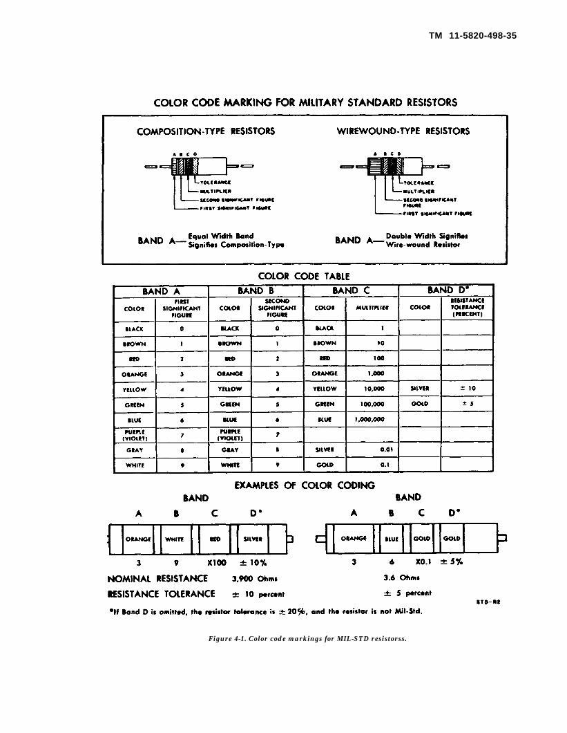
TM 11-5820-498-35
Figure 4-1. Color code markings for MIL-STD resistorss.

By Order of the Secretary of the Army:
Official:KENNETH G. WICKHAM,
TM 11-5820-498-35
W. C. WESTMORELAND,General, United States Army,Chief of Staff.
Major General, United States Army,The Adjutant General.
Distribution:
To be distributed in accordance with DA Form 12-51, Direct and General Support requirementsfor following equipments: AN/GRC-125, AN/VRC-53 and OA-3633/GRC.
*U.S. GOVERNMENT PRINTING OFFICE: 1994-342-421/81111


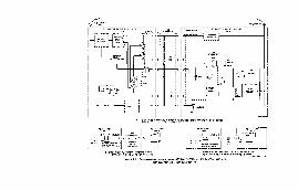


PIN: 030695-000

This fine document...
Was brought to you by me:
Liberated Manuals -- free army and government manuals
Why do I do it? I am tired of sleazy CD-ROM sellers, who take publicly available information, slap “watermarks” and other junk on it, and sell it. Those masters of search engine manipulation make sure that their sites that sell free information, come up first in search engines. They did not create it... They did not even scan it... Why should they get your money? Why are not letting you give those free manuals to your friends?
I am setting this document FREE. This document was made by the US Government and is NOT protected by Copyright. Feel free to share, republish, sell and so on.
I am not asking you for donations, fees or handouts. If you can, please provide a link to liberatedmanuals.com, so that free manuals come up first in search engines:
<A HREF=http://www.liberatedmanuals.com/>Free Military and Government Manuals</A>
– SincerelyIgor Chudovhttp://igor.chudov.com/
– Chicago Machinery Movers