Embed Size (px)
Citation preview
Eaton VFX Product Family Installation and Operation ManualVFX Product Line

EATON VFX Product Family Installation and Operation Manual E-ELCL-II003-E1 October 20142
Warning
Before beginning installation of this product: Read and follow all installation instructions. Please contact Eaton immediately if you have any questions.
Note: This manual was written with great care and precision. However, since the potential for error exists, we can provide no assurance of the absolute accuracy of its contents.
Warranty
In order to consistently bring you the highest quality, full featured products, we reserve the right to change our specifications and designs at any time.
A limited warranty is given with these Eaton products. Please see our website for details. http://www.eaton.com/Eaton/ProductsServices/Hydraulics/WarrantyTermsConditions/PCT_612027
!!
VFX Product Family General Information
EATON VFX Product Family Installation and Operation Manual E-ELCL-II003-E1 November 2014 3
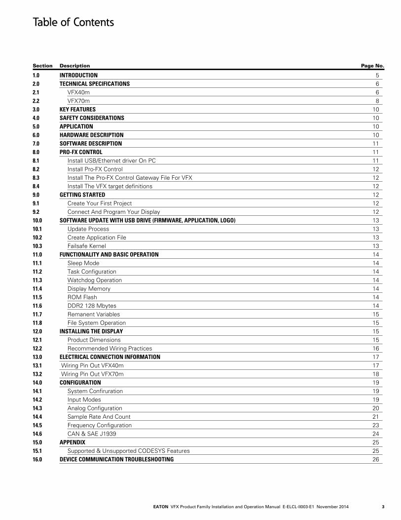
Table of Contents
Section Description Page No.
1.0 INTRODUCTION 52.0 TECHNICAL SPECIFICATIONS 62.1 VFX40m 62.2 VFX70m 83.0 KEY FEATURES 104.0 SAFETY CONSIDERATIONS 105.0 APPLICATION 106.0 HARDWARE DESCRIPTION 107.0 SOFTWARE DESCRIPTION 118.0 PRO-FX CONTROL 118.1 Install USB/Ethernet driver On PC 118.2 Install Pro-FX Control 128.3 Install The Pro-FX Control Gateway File For VFX 128.4 Install The VFX target definitions 129.0 GETTING STARTED 129.1 Create Your First Project 129.2 Connect And Program Your Display 1210.0 SOFTWARE UPDATE WITH USB DRIVE (FIRMWARE, APPLICATION, LOGO) 1310.1 Update Process 1310.2 Create Application File 1310.3 Failsafe Kernel 1311.0 FUNCTIONALITY AND BASIC OPERATION 1411.1 Sleep Mode 1411.2 Task Configuration 1411.3 Watchdog Operation 1411.4 Display Memory 1411.5 ROM Flash 1411.6 DDR2 128 Mbytes 1411.7 Remanent Variables 1511.8 File System Operation 1512.0 INSTALLING THE DISPLAY 1512.1 Product Dimensions 1512.2 Recommended Wiring Practices 1613.0 ELECTRICAL CONNECTION INFORMATION 1713.1 Wiring Pin Out VFX40m 1713.2 Wiring Pin Out VFX70m 1814.0 CONFIGURATION 1914.1 System Confiruration 1914.2 Input Modes 1914.3 Analog Configuration 2014.4 Sample Rate And Count 2114.5 Frequency Configuration 2314.6 CAN & SAE J1939 2415.0 APPENDIX 2515.1 Supported & Unsupported CODESYS Features 2516.0 DEVICE COMMUNICATION TROUBLESHOOTING 26

EATON VFX Product Family Installation and Operation Manual E-ELCL-II003-E1 October 20144
(THIS PAGE INTENTIONALLY LEFT BLANK)
EATON VFX Product Family Installation and Operation Manual E-ELCL-II003-E1 November 2014 5
VFX Product Family
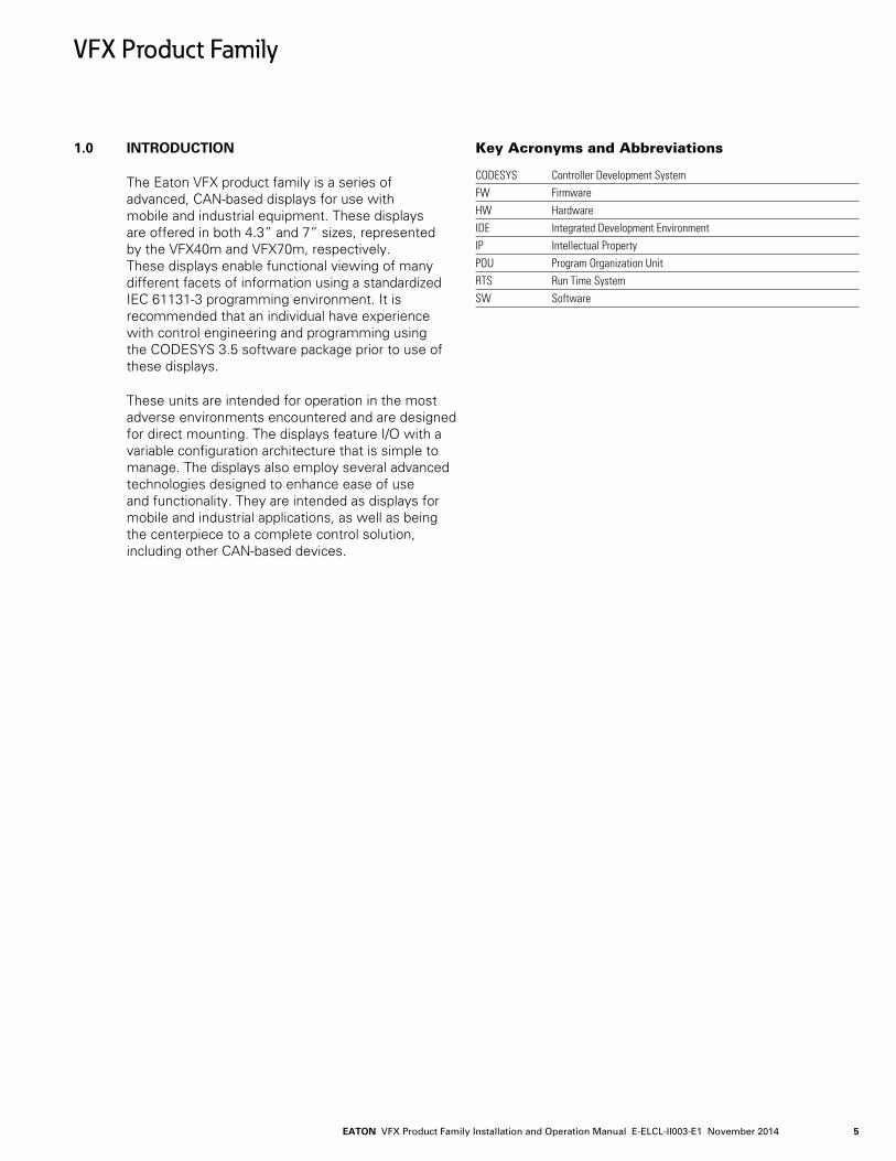
1.0 INTRODUCTION
The Eaton VFX product family is a series of advanced, CAN-based displays for use with mobile and industrial equipment. These displays are offered in both 4.3” and 7” sizes, represented by the VFX40m and VFX70m, respectively. These displays enable functional viewing of many different facets of information using a standardized IEC 61131-3 programming environment. It is recommended that an individual have experience with control engineering and programming using the CODESYS 3.5 software package prior to use of these displays.
These units are intended for operation in the most adverse environments encountered and are designed for direct mounting. The displays feature I/O with a variable configuration architecture that is simple to manage. The displays also employ several advanced technologies designed to enhance ease of use and functionality. They are intended as displays for mobile and industrial applications, as well as being the centerpiece to a complete control solution, including other CAN-based devices.
Key Acronyms and Abbreviations CODESYS Controller Development SystemFW FirmwareHW HardwareIDE Integrated Development EnvironmentIP Intellectual PropertyPOU Program Organization UnitRTS Run Time SystemSW Software
EATON VFX Product Family Installation and Operation Manual E-ELCL-II003-E1 October 20146
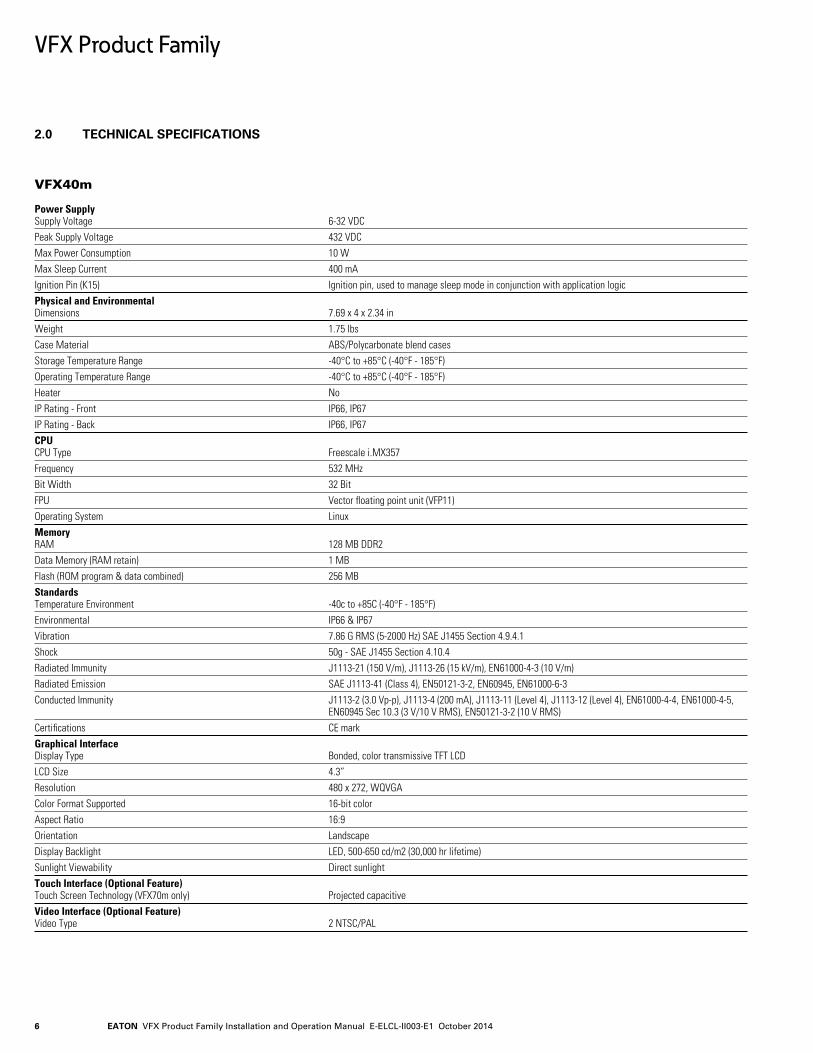
2.0 TECHNICAL SPECIFICATIONS
VFX40m Power Supply Supply Voltage 6-32 VDCPeak Supply Voltage 432 VDCMax Power Consumption 10 W Max Sleep Current 400 mAIgnition Pin (K15) Ignition pin, used to manage sleep mode in conjunction with application logicPhysical and Environmental Dimensions 7.69 x 4 x 2.34 inWeight 1.75 lbsCase Material ABS/Polycarbonate blend casesStorage Temperature Range -40°C to +85°C (-40°F - 185°F)Operating Temperature Range -40°C to +85°C (-40°F - 185°F)Heater NoIP Rating - Front IP66, IP67IP Rating - Back IP66, IP67CPU CPU Type Freescale i.MX357Frequency 532 MHzBit Width 32 BitFPU Vector floating point unit (VFP11)Operating System LinuxMemory RAM 128 MB DDR2Data Memory (RAM retain) 1 MBFlash (ROM program & data combined) 256 MB Standards Temperature Environment -40c to +85C (-40°F - 185°F)Environmental IP66 & IP67Vibration 7.86 G RMS (5-2000 Hz) SAE J1455 Section 4.9.4.1Shock 50g - SAE J1455 Section 4.10.4Radiated Immunity J1113-21 (150 V/m), J1113-26 (15 kV/m), EN61000-4-3 (10 V/m)Radiated Emission SAE J1113-41 (Class 4), EN50121-3-2, EN60945, EN61000-6-3Conducted Immunity J1113-2 (3.0 Vp-p), J1113-4 (200 mA), J1113-11 (Level 4), J1113-12 (Level 4), EN61000-4-4, EN61000-4-5, EN60945 Sec 10.3 (3 V/10 V RMS), EN50121-3-2 (10 V RMS)Certifications CE markGraphical Interface Display Type Bonded, color transmissive TFT LCDLCD Size 4.3”Resolution 480 x 272, WQVGAColor Format Supported 16-bit colorAspect Ratio 16:9Orientation LandscapeDisplay Backlight LED, 500-650 cd/m2 (30,000 hr lifetime)Sunlight Viewability Direct sunlightTouch Interface (Optional Feature) Touch Screen Technology (VFX70m only) Projected capacitiveVideo Interface (Optional Feature) Video Type 2 NTSC/PAL
VFX Product Family
EATON VFX Product Family Installation and Operation Manual E-ELCL-II003-E1 November 2014 7
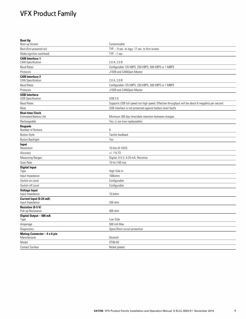
Boot Up Boot-up Screen CustomizableBoot (first powered-on) TYP. ~ 9 sec. to logo, 17 sec. to first screenWake (ignition switched) TYP. ~1 sec.CAN Interface 1 CAN Specification 2.0 A, 2.0 BBaud Rates Configurable 125 KBPS, 250 KBPS, 500 KBPS or 1 MBPSProtocols J1939 and CANOpen MasterCAN Interface 2 CAN Specification 2.0 A, 2.0 BBaud Rates Configurable 125 KBPS, 250 KBPS, 500 KBPS or 1 MBPSProtocols J1939 and CANOpen MasterUSB Interface USB Specification USB 2.0Baud Rates Supports USB full speed not high speed. Effective throughput will be about 6 megabits per secondNote USB interface is not protected against battery level faultsReal-time Clock Estimated Battery Life Minimum 300 day time/date retention between chargesRechargeable Yes, Li-ion (non-replaceable)Keypads Number of Buttons 8Button Style Tactile feedbackButton Backlight YesInput Resolution 10 bits (0-1023)Accuracy +/- 1% FSMeasuring Ranges Digital, 0-5 V, 4-20 mA, ResistiveScan Rate 10 Hz (100 ms)Digital Input Type High Side InInput Impedance 100kohmSwitch-on Level ConfigurableSwitch-off Level ConfigurableVoltage Input Input Impedance 10 kohmCurrent Input (0-24 mA) Input Impedance 200 ohmResistive (0-5 V) Pull-up Resistance 400 ohmDigital Output – 500 mA Type Low SideAmperage 500 mA MaxDiagnostics Open/Short circuit protectionMating Connector – 4 x 6 pin Manufacturer DeutschModel DT06-6SContact Surface Nickel plated
VFX Product Family
EATON VFX Product Family Installation and Operation Manual E-ELCL-II003-E1 October 20148
VFX Product Family
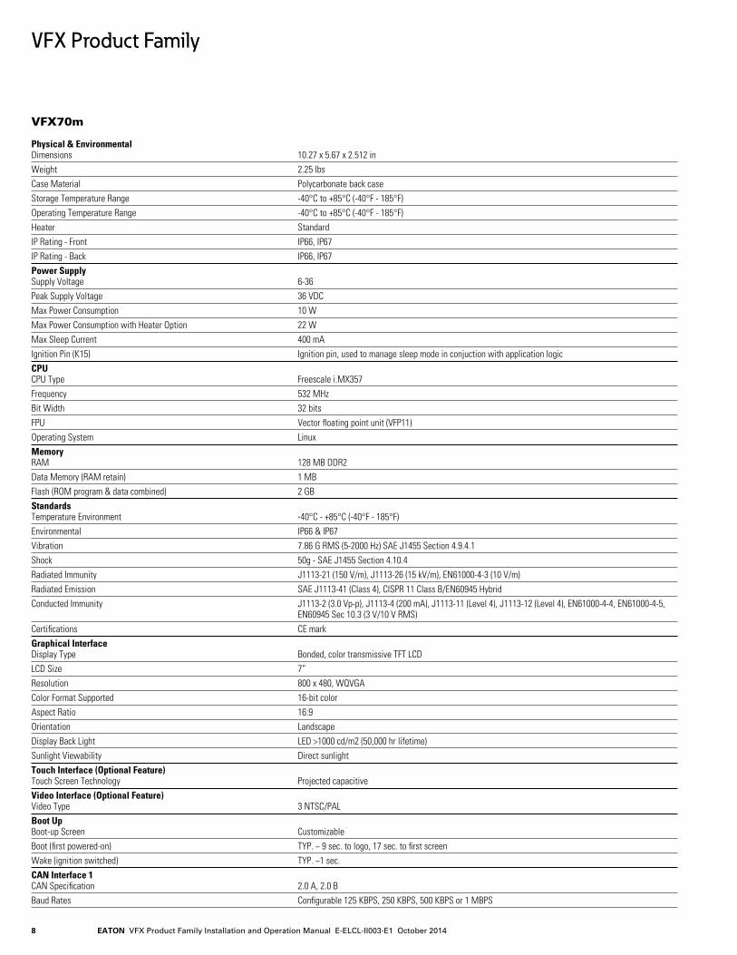
VFX70m Physical & Environmental Dimensions 10.27 x 5.67 x 2.512 inWeight 2.25 lbsCase Material Polycarbonate back caseStorage Temperature Range -40°C to +85°C (-40°F - 185°F)Operating Temperature Range -40°C to +85°C (-40°F - 185°F)Heater StandardIP Rating - Front IP66, IP67 IP Rating - Back IP66, IP67Power Supply Supply Voltage 6-36Peak Supply Voltage 36 VDCMax Power Consumption 10 WMax Power Consumption with Heater Option 22 WMax Sleep Current 400 mAIgnition Pin (K15) Ignition pin, used to manage sleep mode in conjuction with application logic CPU CPU Type Freescale i.MX357Frequency 532 MHzBit Width 32 bitsFPU Vector floating point unit (VFP11)Operating System LinuxMemory RAM 128 MB DDR2Data Memory (RAM retain) 1 MBFlash (ROM program & data combined) 2 GBStandards Temperature Environment -40°C - +85°C (-40°F - 185°F)Environmental IP66 & IP67Vibration 7.86 G RMS (5-2000 Hz) SAE J1455 Section 4.9.4.1Shock 50g - SAE J1455 Section 4.10.4Radiated Immunity J1113-21 (150 V/m), J1113-26 (15 kV/m), EN61000-4-3 (10 V/m)Radiated Emission SAE J1113-41 (Class 4), CISPR 11 Class B/EN60945 HybridConducted Immunity J1113-2 (3.0 Vp-p), J1113-4 (200 mA), J1113-11 (Level 4), J1113-12 (Level 4), EN61000-4-4, EN61000-4-5, EN60945 Sec 10.3 (3 V/10 V RMS)Certifications CE markGraphical Interface Display Type Bonded, color transmissive TFT LCDLCD Size 7”Resolution 800 x 480, WQVGAColor Format Supported 16-bit colorAspect Ratio 16:9Orientation LandscapeDisplay Back Light LED >1000 cd/m2 (50,000 hr lifetime)Sunlight Viewability Direct sunlightTouch Interface (Optional Feature) Touch Screen Technology Projected capacitiveVideo Interface (Optional Feature) Video Type 3 NTSC/PALBoot Up Boot-up Screen CustomizableBoot (first powered-on) TYP. ~ 9 sec. to logo, 17 sec. to first screenWake (ignition switched) TYP. ~1 sec.CAN Interface 1 CAN Specification 2.0 A, 2.0 BBaud Rates Configurable 125 KBPS, 250 KBPS, 500 KBPS or 1 MBPS
EATON VFX Product Family Installation and Operation Manual E-ELCL-II003-E1 November 2014 9
VFX Product Family
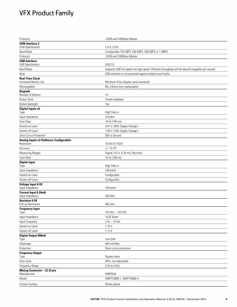
Protocols J1939 and CANOpen MasterCAN Interface 2 CAN Specification 2.0 A, 2.0 BBaud Rates Configurable 125 KBPS, 250 KBPS, 500 KBPS or 1 MBPSProtocols J1939 and CANOpen MasterUSB Interface USB Specification USB 2.0Baud Rates Supports USB full speed not high speed. Effective throughput will be about 6 megabits per secondNote USB interface is not protected against battery level faultsReal Time Clock Estimated Battery Life Minimum 9.5yr (display never powered)Rechargeable No, Lithium (non-replaceable)Keypads Number of Buttons 14Button Style Tactile feedbackButton Backlight YesDigital Inputs x5 Type High Side inInput Impedance 10 kohmScan Rate 10 Hz (100 ms)Switch-on Level 4.01 V ( 80% Supply Voltage )Switch-off Level 1.04 V ( 20% Supply Voltage )Short Circuit Protection 28V or GroundAnalog Inputs x3 (Software Configurable) Resolution 10 bits (0-1023)Accuracy +/- 1% FSMeasuring Ranges Digital, 0-5 V, 4-20 mA, ResistiveScan Rate 10 Hz (100 ms)Digital Input Type High Side inInput Impedance 100 kohmSwitch-on Level ConfigurableSwitch-off Level ConfigurableVoltage Input 0-5V Input Impedance 100 kohmCurrent Input 0-24mA Input Impedance 200 ohmResistive 0-5V Pull-up Resistance 400 ohmFrequency Input Type 3.6 VAC – 120 VACInput Impedance 14.02 KohmInput Frequency 2 Hz – 10 kHzSwitch-on Level 2.10 VSwitch-off Level 1.17 VDigital Output 500mA Type Low SideAmperage 500 mA Max.Protection Short circuit protectionFrequency Output Type Square waveDuty Cycle 50%, non-adjustableFrequency Range 2 Hz to 3 kHzMating Connector – (2) 23 pin Manufacturer AMPSEALModel AMP770680-1, AMP770680-4
Contact Surface Nickel plated
EATON VFX Product Family Installation and Operation Manual E-ELCL-II003-E1 October 201410
3.0 KEY FEATURES
• Completely protected outputs (thermal and overcurrent)
• Reverse polarity protection
• Up to 11 inputs, depending on model
• Up to 2 outputs, depending on model
• Programmable via USB
• Two CAN ports
• Sleep input for improved power management
4.0 SAFETY CONSIDERATIONS
Please note: These instructions are intended for use by a competent programmer, electrician, technician or engineer. These instructions should be read and kept as a reference prior to display installation and use. Incorrect operation of the display can present a significant threat to both individuals and equipment. In the event of a break down, do not attempt to repair the display as there are no user serviceable parts inside the enclosure. Any evidence of tampering will invalidate the warranty.
5.0 APPLICATION
This operating and installation manual should be used in conjunction with the online help provided with the Pro-FX Control 1.1 development environment. Together, this information should form a basis for the simple configuration of the display and the creation of programs specific to your application needs. The correct operation and function of the display is dependent on the program that is created and ultimately downloaded to the hardware, therefore extensive testing is required. Customers programming the display possess the responsibility of ensuring that the display performs as intended.
Please note: These displays require the installation of appropriate firmware and a hardware-specific description file and libraries before initial use in the application environment.
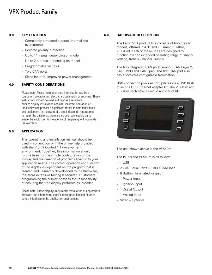
6.0 HARDWARE DESCRIPTION
The Eaton VFX product line consists of two display models, offered in 4.3” and 7” sizes (VFX40m, VFX70m). Each of these units are designed to function over an extended operating range of supply voltage, from 6 – 36 VDC supply.
The two integrated CAN ports support CAN Layer 2, SAE J1939 and CANOpen. The first CAN port also has a software configurable termination.
USB connection provides for updates via a USB flash drive or a USB Ethernet adapter kit. The VFX40m and VFX70m each have a unique number of I/O.
The unit shown above is the VFX40m.
The I/O for the VFX40m is as follows:
• 1 USB
• 2 CAN Serial Ports – J1939/CANOpen
• 8 Button Illuminated Keypad
• 1 Power Input
• 1 Ignition Input
• 1 Digital Output
• 1 Analog Input
• Video – Optional
VFX Product Family
EATON VFX Product Family Installation and Operation Manual E-ELCL-II003-E1 November 2014 11
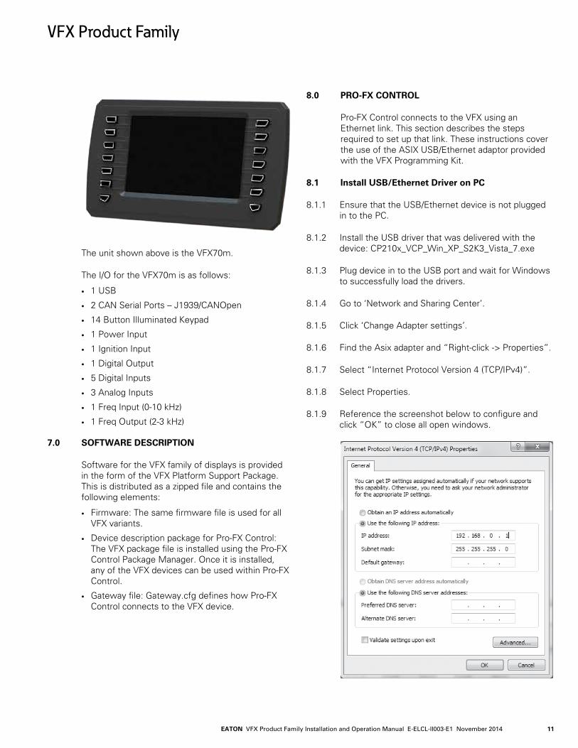
The unit shown above is the VFX70m.
The I/O for the VFX70m is as follows:
• 1 USB
• 2 CAN Serial Ports – J1939/CANOpen
• 14 Button Illuminated Keypad
• 1 Power Input
• 1 Ignition Input
• 1 Digital Output
• 5 Digital Inputs
• 3 Analog Inputs
• 1 Freq Input (0-10 kHz)
• 1 Freq Output (2-3 kHz)
7.0 SOFTWARE DESCRIPTION
Software for the VFX family of displays is provided in the form of the VFX Platform Support Package. This is distributed as a zipped file and contains the following elements:
• Firmware: The same firmware file is used for all VFX variants.
• Device description package for Pro-FX Control: The VFX package file is installed using the Pro-FX Control Package Manager. Once it is installed, any of the VFX devices can be used within Pro-FX Control.
• Gateway file: Gateway.cfg defines how Pro-FX Control connects to the VFX device.
8.0 PRO-FX CONTROL
Pro-FX Control connects to the VFX using an Ethernet link. This section describes the steps required to set up that link. These instructions cover the use of the ASIX USB/Ethernet adaptor provided with the VFX Programming Kit.
8.1 Install USB/Ethernet Driver on PC
8.1.1 Ensure that the USB/Ethernet device is not plugged in to the PC.
8.1.2 Install the USB driver that was delivered with the device: CP210x_VCP_Win_XP_S2K3_Vista_7.exe
8.1.3 Plug device in to the USB port and wait for Windows to successfully load the drivers.
8.1.4 Go to ‘Network and Sharing Center’.
8.1.5 Click ‘Change Adapter settings’.
8.1.6 Find the Asix adapter and “Right-click -> Properties”.
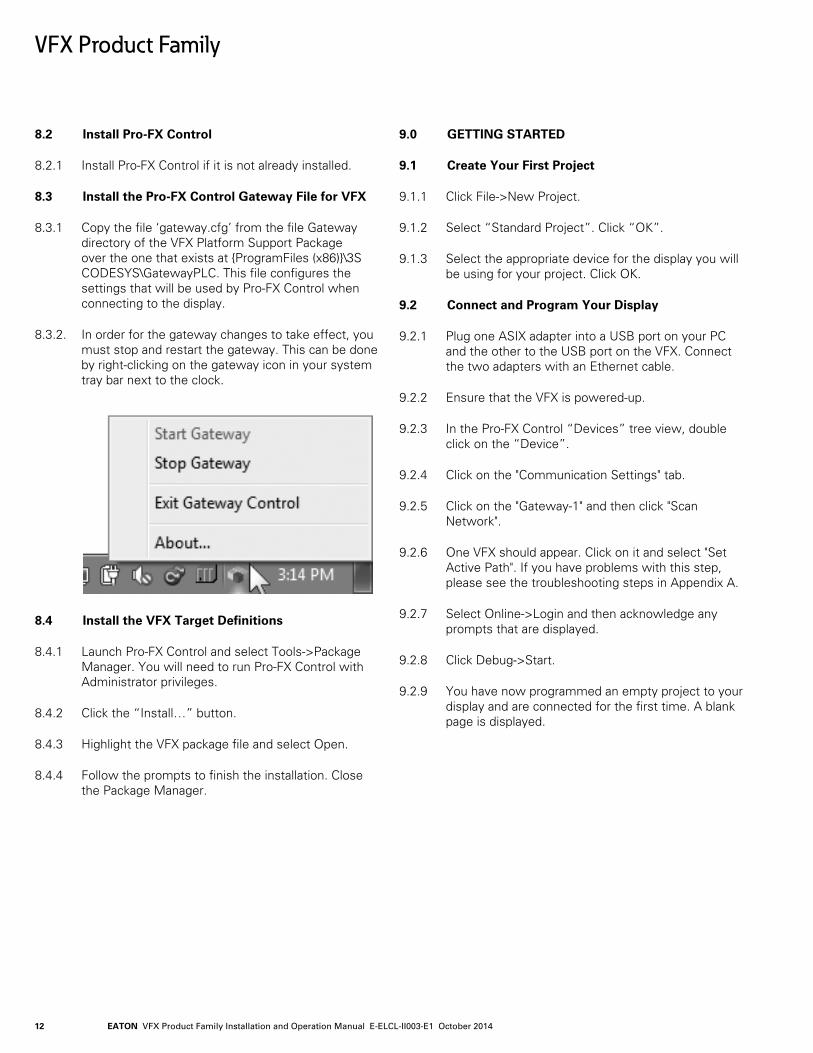
8.1.7 Select “Internet Protocol Version 4 (TCP/IPv4)”.
8.1.8 Select Properties.
8.1.9 Reference the screenshot below to configure and click “OK” to close all open windows.
VFX Product Family
EATON VFX Product Family Installation and Operation Manual E-ELCL-II003-E1 October 201412
VFX Product Family
8.2 Install Pro-FX Control
8.2.1 Install Pro-FX Control if it is not already installed.
8.3 Install the Pro-FX Control Gateway File for VFX
8.3.1 Copy the file ‘gateway.cfg’ from the file Gateway directory of the VFX Platform Support Package over the one that exists at ProgramFiles (x86)\3S CODESYS\GatewayPLC. This file configures the settings that will be used by Pro-FX Control when connecting to the display.
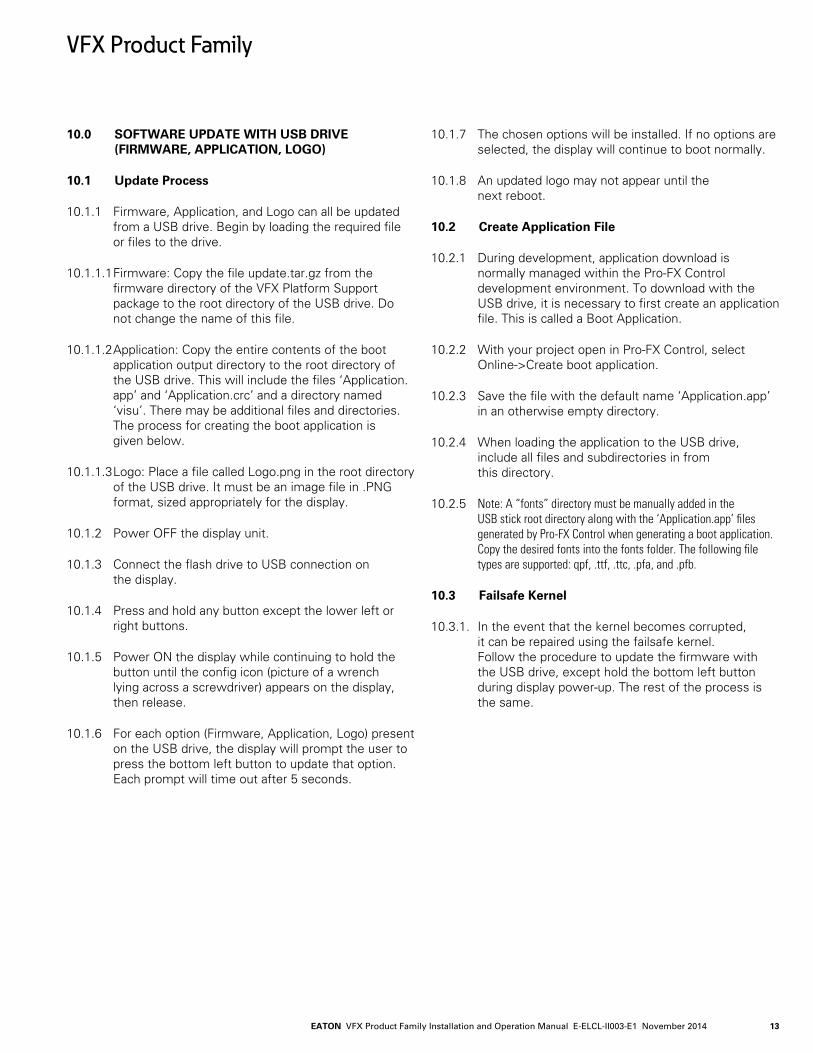
8.3.2. In order for the gateway changes to take effect, you must stop and restart the gateway. This can be done by right-clicking on the gateway icon in your system tray bar next to the clock.
8.4 Install the VFX Target Definitions
8.4.1 Launch Pro-FX Control and select Tools->Package Manager. You will need to run Pro-FX Control with Administrator privileges.
8.4.2 Click the “Install…” button.
8.4.3 Highlight the VFX package file and select Open.
8.4.4 Follow the prompts to finish the installation. Close the Package Manager.
9.0 GETTING STARTED
9.1 Create Your First Project
9.1.1 Click File->New Project.
9.1.2 Select “Standard Project”. Click “OK”.
9.1.3 Select the appropriate device for the display you will be using for your project. Click OK.
9.2 Connect and Program Your Display
9.2.1 Plug one ASIX adapter into a USB port on your PC and the other to the USB port on the VFX. Connect the two adapters with an Ethernet cable.
9.2.2 Ensure that the VFX is powered-up.
9.2.3 In the Pro-FX Control “Devices” tree view, double click on the “Device”.
9.2.4 Click on the "Communication Settings" tab.
9.2.5 Click on the "Gateway-1" and then click "Scan Network".
9.2.6 One VFX should appear. Click on it and select "Set Active Path". If you have problems with this step, please see the troubleshooting steps in Appendix A.
9.2.7 Select Online->Login and then acknowledge any prompts that are displayed.
9.2.8 Click Debug->Start.
9.2.9 You have now programmed an empty project to your display and are connected for the first time. A blank page is displayed.
EATON VFX Product Family Installation and Operation Manual E-ELCL-II003-E1 November 2014 13
VFX Product Family
10.0 SOFTWARE UPDATE WITH USB DRIVE (FIRMWARE, APPLICATION, LOGO)
10.1 Update Process
10.1.1 Firmware, Application, and Logo can all be updated from a USB drive. Begin by loading the required file or files to the drive.
10.1.1.1 Firmware: Copy the file update.tar.gz from the firmware directory of the VFX Platform Support package to the root directory of the USB drive. Do not change the name of this file.
10.1.1.2 Application: Copy the entire contents of the boot application output directory to the root directory of the USB drive. This will include the files ‘Application.app’ and ‘Application.crc’ and a directory named ‘visu’. There may be additional files and directories. The process for creating the boot application is given below.
10.1.1.3 Logo: Place a file called Logo.png in the root directory of the USB drive. It must be an image file in .PNG format, sized appropriately for the display.
10.1.2 Power OFF the display unit.
10.1.3 Connect the flash drive to USB connection on the display.
10.1.4 Press and hold any button except the lower left or right buttons.
10.1.5 Power ON the display while continuing to hold the button until the config icon (picture of a wrench lying across a screwdriver) appears on the display, then release.
10.1.6 For each option (Firmware, Application, Logo) present on the USB drive, the display will prompt the user to press the bottom left button to update that option. Each prompt will time out after 5 seconds.
10.1.7 The chosen options will be installed. If no options are selected, the display will continue to boot normally.
10.1.8 An updated logo may not appear until the next reboot.
10.2 Create Application File
10.2.1 During development, application download is normally managed within the Pro-FX Control development environment. To download with the USB drive, it is necessary to first create an application file. This is called a Boot Application.
10.2.2 With your project open in Pro-FX Control, select Online->Create boot application.
10.2.3 Save the file with the default name ‘Application.app’ in an otherwise empty directory.
10.2.4 When loading the application to the USB drive, include all files and subdirectories in from this directory.
10.2.5 Note: A “fonts” directory must be manually added in the USB stick root directory along with the ‘Application.app’ files generated by Pro-FX Control when generating a boot application. Copy the desired fonts into the fonts folder. The following file types are supported: qpf, .ttf, .ttc, .pfa, and .pfb.
10.3 Failsafe Kernel
10.3.1. In the event that the kernel becomes corrupted, it can be repaired using the failsafe kernel. Follow the procedure to update the firmware with the USB drive, except hold the bottom left button during display power-up. The rest of the process is the same.
EATON VFX Product Family Installation and Operation Manual E-ELCL-II003-E1 October 201414
VFX Product Family
11.0 FUNCTIONALITY AND BASIC OPERATION
11.1 Sleep Mode
Ignition pin is required for initial power up of the display. Once the display is powered, it provides a mechanism to have a controlled shutdown of the display in conjunction with a user application. This is beneficial because the unit can be put into an idle state where less current is required, thus extending battery life. It is also of benefit in applications where parameters are required to be set to a safe state and retained prior to shutdown. Ignition input is hardware-debounced and sets the IgnitionPin variable at approximately 6.6 V.
The display will enter sleep by setting the sleep variable "enterStandby" (System Config > System Config I/O Mapping > System State > enterStandby) anytime that the IGN is low or not connected. The display will awaken from sleep if the IGN is high.
11.2 Task Configuration
The display supports the following tasks:
• Cyclic
• Freewheeling
• Event
• Status
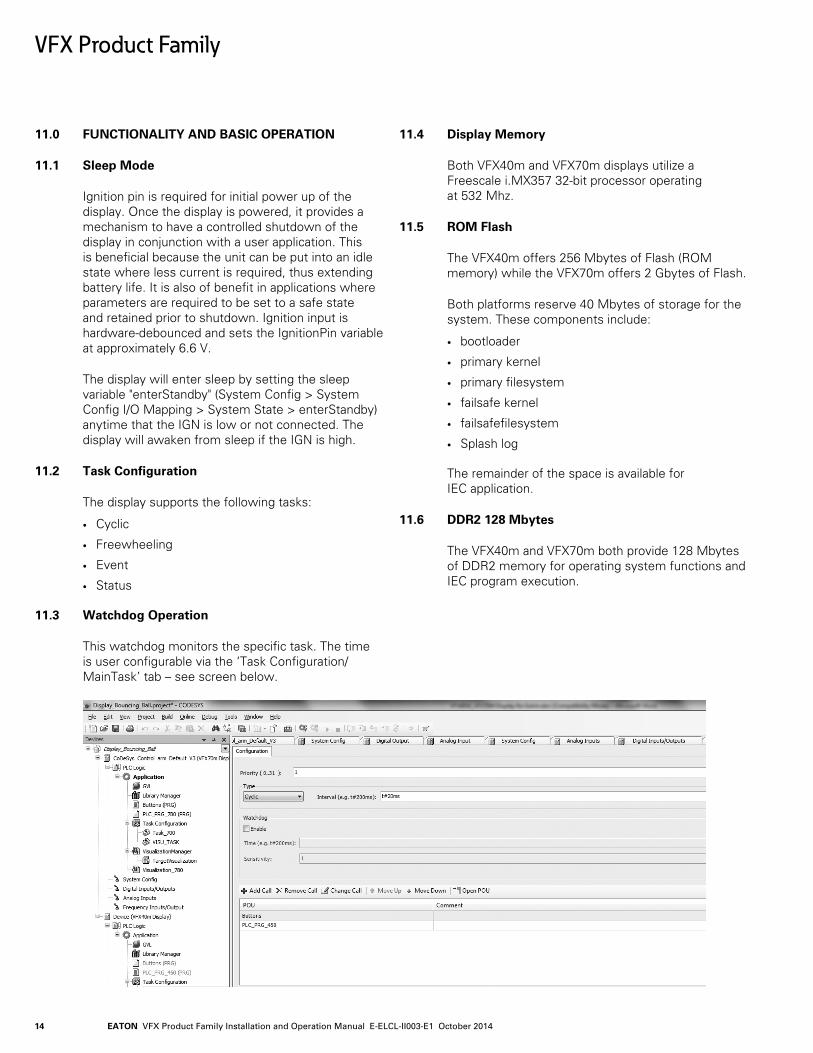
11.3 Watchdog Operation
This watchdog monitors the specific task. The time is user configurable via the ‘Task Configuration/MainTask’ tab – see screen below.
11.4 Display Memory
Both VFX40m and VFX70m displays utilize a Freescale i.MX357 32-bit processor operating at 532 Mhz.
11.5 ROM Flash
The VFX40m offers 256 Mbytes of Flash (ROM memory) while the VFX70m offers 2 Gbytes of Flash.
Both platforms reserve 40 Mbytes of storage for the system. These components include:
• bootloader
• primary kernel
• primary filesystem
• failsafe kernel
• failsafefilesystem
• Splash log
The remainder of the space is available for IEC application.
11.6 DDR2 128 Mbytes
The VFX40m and VFX70m both provide 128 Mbytes of DDR2 memory for operating system functions and IEC program execution.
EATON VFX Product Family Installation and Operation Manual E-ELCL-II003-E1 November 2014 15
VFX Product Family
11.7 Remanent Variables
These are variables that can retain their value throughout the usual program run period. They are declared as 'Retain Variables', or even more stringent, as 'Persistent Variables'. For each case, a separate memory area is used.
The declaration determines the degree of "resistance" for a remanent variable in the case of resets, downloads or a reboot of the PLC. In applications, the combination of both remanent flags will be required.
The following table indicates how variables behave: VAR PERSISTENT / After Online VAR VAR RETAIN PERSISTENT / command VAR RETAIN VAR PERSISTENT RETAIN
Power cycle - x xReset warm - x x <application>Reset cold - - x <application>Reset origin - - - <application>Download - - x <application>
11.8 File System Operation
In addition to providing storage for the operating system, the flash file system also provides storage for additional information (e.g. configuration, license files for libraries, calibration, hardware or software details, options, etc.).
Pro-FX Control has a graphical interface for transferring files between the PC and the display.
Programmable access to the file system is managed through libraries such as the SysFile library (e.g. SysFileOpen, SysFileRead, SysFileWrite functions). The maximum directory and file name size is 16 characters.
12.0 INSTALLING THE DISPLAY
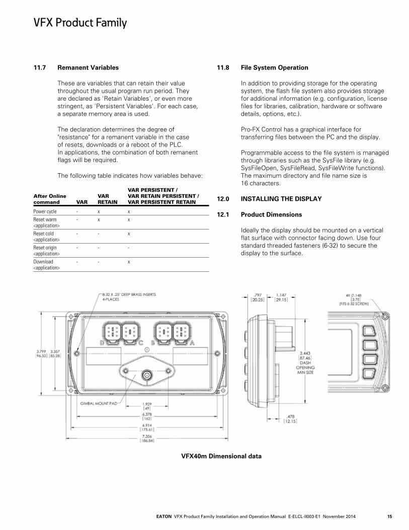
12.1 Product Dimensions
Ideally the display should be mounted on a vertical flat surface with connector facing down. Use four standard threaded fasteners (6-32) to secure the display to the surface.
VFX40m Dimensional data
EATON VFX Product Family Installation and Operation Manual E-ELCL-II003-E1 October 201416
VFX Product Family
12.2 Recommended Wiring Practices
This section contains information about the display connectors and pin outs. Please use the following recommended wiring practices when installing and using the display:
• Ensure correct and adequate single point ground to prevent ground loops.
• Use twisted or twisted shielded pair cable for CAN per the applicable standard.
• Confirm that the CAN network is properly terminated using 120 Ω resistors.
• Ensure the appropriate sized conductor cross section is specified for the intended load current in the harness design. Note: Please review individual overcurrent shutdown values in the configuration and use the correct wire gauge conductor to accommodate maximum load current configured.
• Make sure that voltage drops are kept within reasonable levels under maximum continuous load conditions (e.g. 1 volt on 12-volt systems and 2 volts on 24-volt systems).
• Verify that the harness is constructed to meet the needs of the application environment (e.g. shock, vibration, moisture, temperature, chemicals and impact).
• Make certain that the harness is designed and constructed to minimize induced interference resulting from EMI coupling between signal wires.
• Separate power circuits from low-level signals.
• All splices (soldered or crimped) should use adhesive-lined heat shrink tubing.
• Make provisions for drip loops to attach devices in exposed locations and prevent moisture entry and formation.
• Provide sufficient clearance from moving parts.
• Wires routed through holes in the vehicle body/chassis should use grommets.
• Avoid sharp metal edges, fasteners and other abrasive surfaces or use protective shielding when routing harness assembly.
• Route wires to avoid exhaust system components or other high temperature areas. Use appropriate heat shielding or other insulation where routing is a problem.
• Avoid routing near wheel wells or provide adequate mechanical protection to the assembly.
• Use a protective fuse sized appropriately for the display supply current. Note: 5A fuse maximum is typical. Verify that wiring can handle more current than the fuse rating.
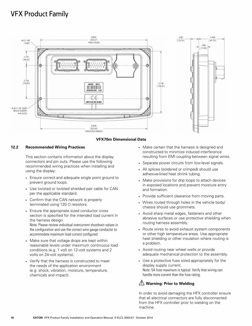
VFX70m Dimensional Data
! Warning: Prior to Welding
In order to avoid damaging the HFX controller ensure that all electrical connectors are fully disconnected from the HFX controller prior to welding on the machine.
EATON VFX Product Family Installation and Operation Manual E-ELCL-II003-E1 November 2014 17
VFX Product Family
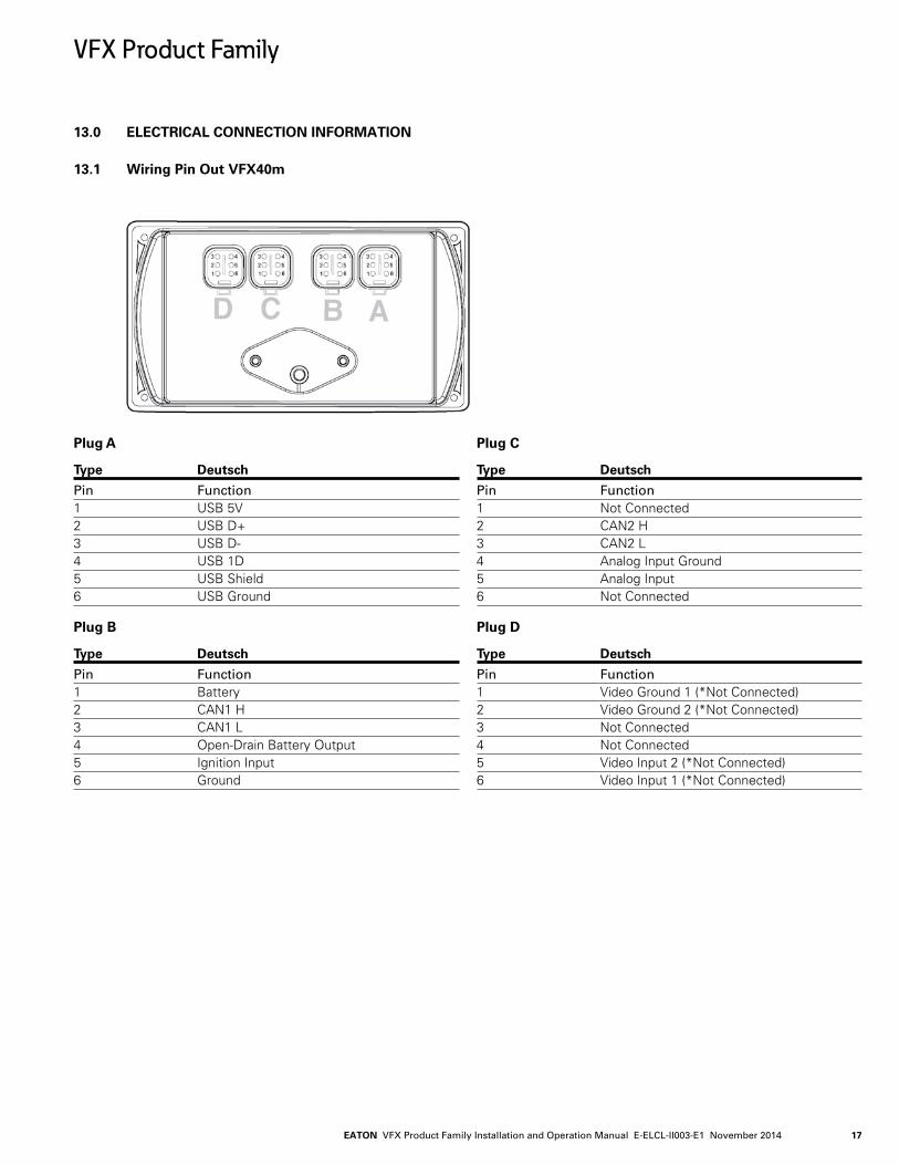
13.0 ELECTRICAL CONNECTION INFORMATION
Plug A Type Deutsch
Pin Function1 USB 5V2 USB D+3 USB D-4 USB 1D5 USB Shield6 USB Ground Plug B Type Deutsch
Pin Function1 Battery2 CAN1 H3 CAN1 L4 Open-Drain Battery Output5 Ignition Input6 Ground
Plug C Type Deutsch
Pin Function1 Not Connected2 CAN2 H3 CAN2 L4 Analog Input Ground5 Analog Input6 Not Connected Plug D Type Deutsch
Pin Function1 Video Ground 1 (*Not Connected)2 Video Ground 2 (*Not Connected)3 Not Connected4 Not Connected5 Video Input 2 (*Not Connected)6 Video Input 1 (*Not Connected)
Powerview 450 Backview *(Pin Not Connected on Version without Video).
13.1 Wiring Pin Out VFX40m
EATON VFX Product Family Installation and Operation Manual E-ELCL-II003-E1 October 201418
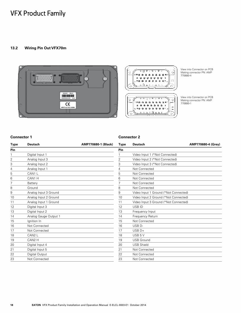
13.2 Wiring Pin Out VFX70m
VFX Product Family
View into Connector on PCB Mating connector PN: AMP 770680-4
View into Connector on PCB Mating connector PN: AMP 770680-1
Connector 1
Type Deutsch AMP770680-1 (Black)
Pin
1 Digital Input 12 Analog Input 33 Analog Input 2 4 Analog Input 1 5 CAN1 L 6 CAN1 H 7 Battery 8 Ground 9 Analog Input 3 Ground 10 Analog Input 2 Ground11 Analog Input 1 Ground12 Digital Input 3 13 Digital Input 2 14 Analog Gauge Output 1 15 Ignition In 16 Not Connected 17 Not Connected 18 CAN2 L 19 CAN2 H 20 Digital Input 4 21 Digital Input 5 22 Digital Output 23 Not Connected
Connector 2 Type Deutsch AMP770680-4 (Grey)
Pin 1 Video Input 1 (*Not Connected) 2 Video Input 2 (*Not Connected) 3 Video Input 3 (*Not Connected) 4 Not Connected 5 Not Connected 6 Not Connected 7 Not Connected 8 Not Connected 9 Video Input 1 Ground (*Not Connected) 10 Video Input 2 Ground (*Not Connected) 11 Video Input 3 Ground (*Not Connected) 12 USB ID 13 Frequency Input 14 Frequency Return 15 Not Connected 16 USB D- 17 USB D+ 18 USB 5 V 19 USB Ground 20 USB Shield 21 Not Connected 22 Not Connected 23 Not Connected
EATON VFX Product Family Installation and Operation Manual E-ELCL-II003-E1 November 2014 19
14.0 CONFIGURATION
14.1 System Configuration
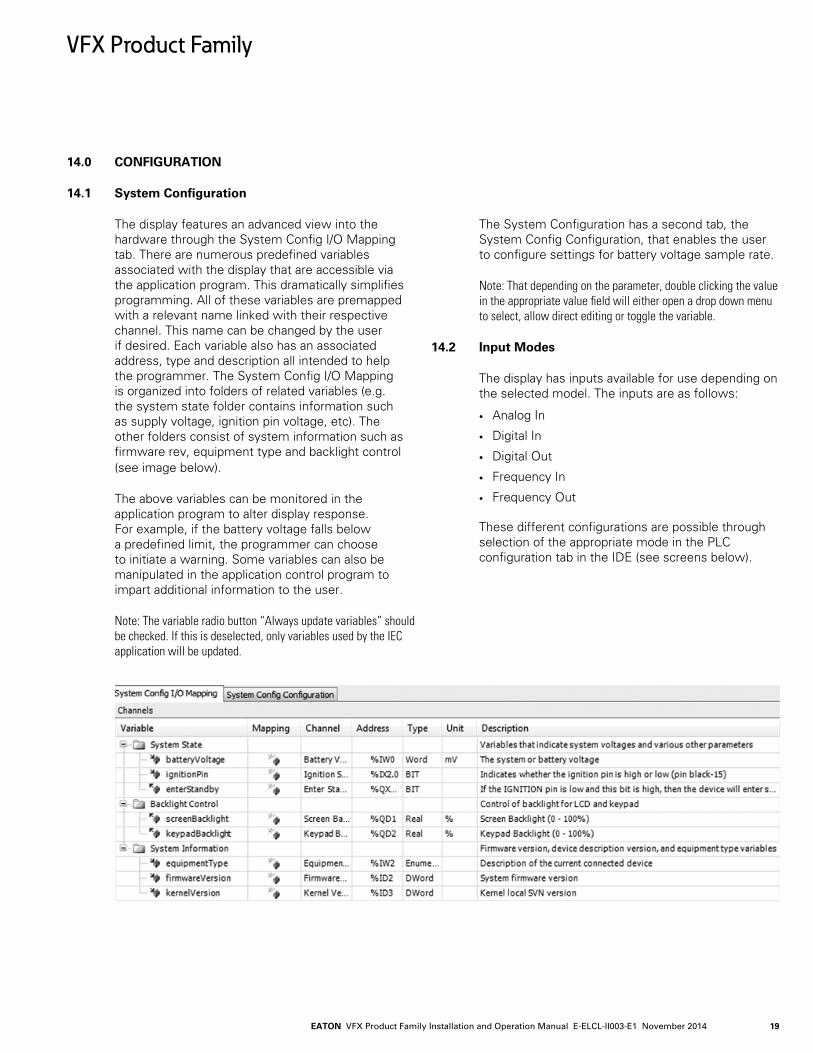
The display features an advanced view into the hardware through the System Config I/O Mapping tab. There are numerous predefined variables associated with the display that are accessible via the application program. This dramatically simplifies programming. All of these variables are premapped with a relevant name linked with their respective channel. This name can be changed by the user if desired. Each variable also has an associated address, type and description all intended to help the programmer. The System Config I/O Mapping is organized into folders of related variables (e.g. the system state folder contains information such as supply voltage, ignition pin voltage, etc). The other folders consist of system information such as firmware rev, equipment type and backlight control (see image below).
The above variables can be monitored in the application program to alter display response. For example, if the battery voltage falls below a predefined limit, the programmer can choose to initiate a warning. Some variables can also be manipulated in the application control program to impart additional information to the user.
Note: The variable radio button “Always update variables” should be checked. If this is deselected, only variables used by the IEC application will be updated.
The System Configuration has a second tab, the System Config Configuration, that enables the user to configure settings for battery voltage sample rate.
Note: That depending on the parameter, double clicking the value in the appropriate value field will either open a drop down menu to select, allow direct editing or toggle the variable.
14.2 Input Modes
The display has inputs available for use depending on the selected model. The inputs are as follows:
• Analog In
• Digital In
• Digital Out
• Frequency In
• Frequency Out
These different configurations are possible through selection of the appropriate mode in the PLC configuration tab in the IDE (see screens below).
VFX Product Family
EATON VFX Product Family Installation and Operation Manual E-ELCL-II003-E1 October 201420
VFX Product Family
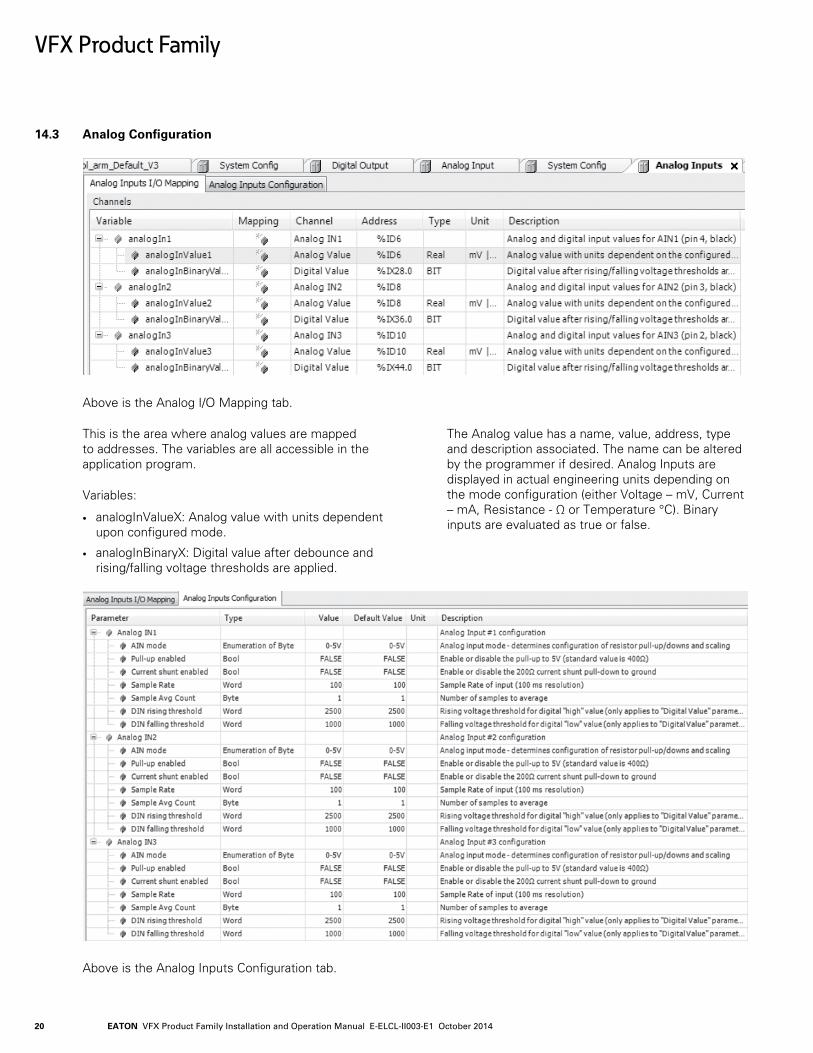
14.3 Analog Configuration
Above is the Analog I/O Mapping tab.
This is the area where analog values are mapped to addresses. The variables are all accessible in the application program.
Variables:
• analogInValueX: Analog value with units dependent upon configured mode.
• analogInBinaryX: Digital value after debounce and rising/falling voltage thresholds are applied.
The Analog value has a name, value, address, type and description associated. The name can be altered by the programmer if desired. Analog Inputs are displayed in actual engineering units depending on the mode configuration (either Voltage – mV, Current – mA, Resistance - Ω or Temperature °C). Binary inputs are evaluated as true or false.
Above is the Analog Inputs Configuration tab.
EATON VFX Product Family Installation and Operation Manual E-ELCL-II003-E1 November 2014 21
VFX Product Family
The programmer changes the configuration of an individual input using the AIN mode value drop down selection. Note that if any of the following auto configurations is selected offline, the state of the corresponding pull-up, pull-down and current shunt will change once the program is downloaded into the application controller.
Variables:
• AIN Mode: This represents the type of input connected.
• Pull-Up Enabled: This is used in manual mode to activate the Pull-up resistor.
• Pull-Down Enabled: This is used in manual mode to activate the Pull-down resistor.
• Current Shunt Enabled: This is used in manual mode to activate the Current shunt resistor.
• DIN Rising Threshold: This sets the lower limit voltage level necessary for the input to register as high.
• DIN Falling Threshold: This sets the upper limit voltage level necessary for the input to register as low. Used in conjunction with the above DIN rising threshold, an appropriate hysteresis level can be defined.
• Sample Rate: This sets the sample rate of input (i.e., ## ms/revolution).
• Sample Average Count: This sets the number of samples to average.
Make sure to take into consideration the effect of hysteresis (e.g. have some margin between rising and falling thresholds).
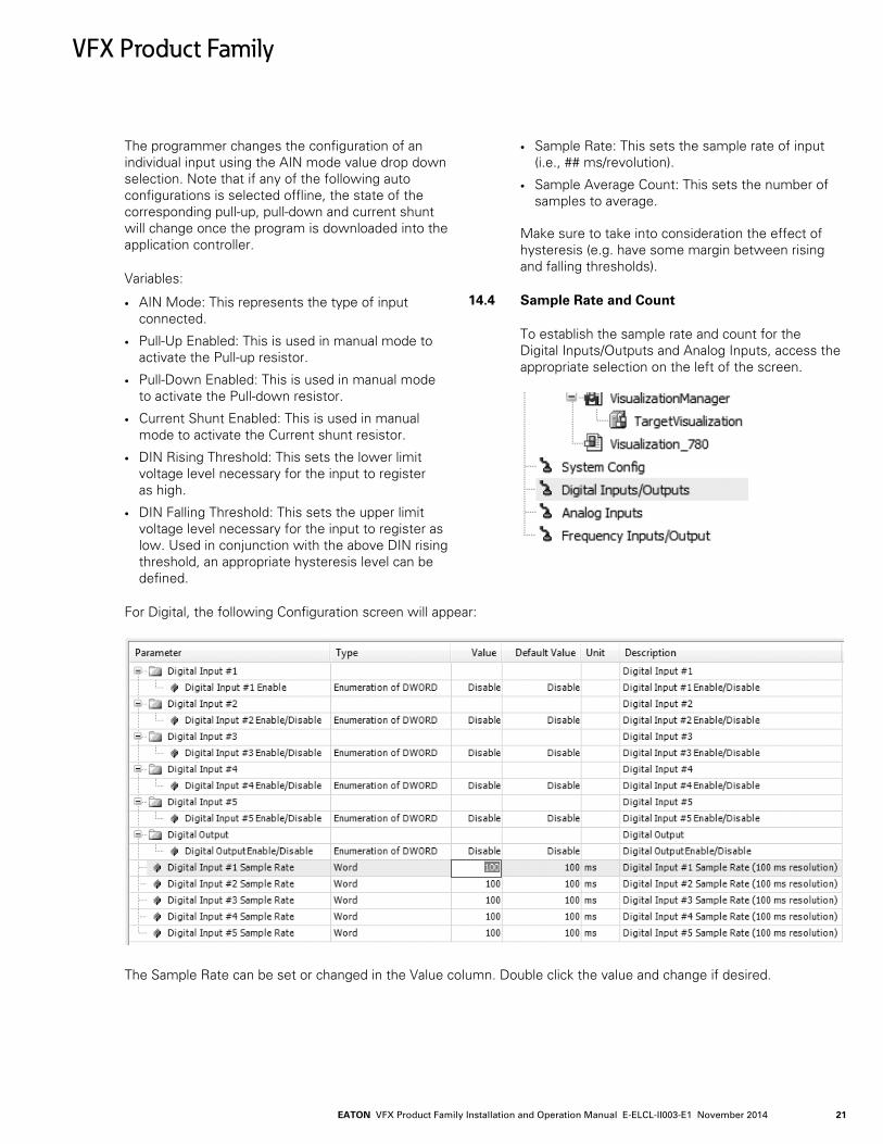
14.4 Sample Rate and Count
To establish the sample rate and count for the Digital Inputs/Outputs and Analog Inputs, access the appropriate selection on the left of the screen.
For Digital, the following Configuration screen will appear:
The Sample Rate can be set or changed in the Value column. Double click the value and change if desired.
EATON VFX Product Family Installation and Operation Manual E-ELCL-II003-E1 October 201422
VFX Product Family
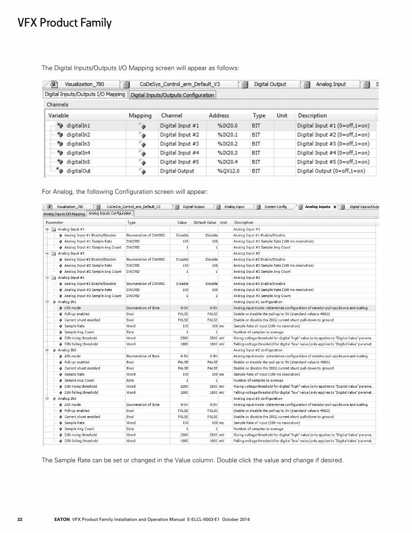
The Digital Inputs/Outputs I/O Mapping screen will appear as follows:
For Analog, the following Configuration screen will appear:
The Sample Rate can be set or changed in the Value column. Double click the value and change if desired.
EATON VFX Product Family Installation and Operation Manual E-ELCL-II003-E1 November 2014 23
VFX Product Family
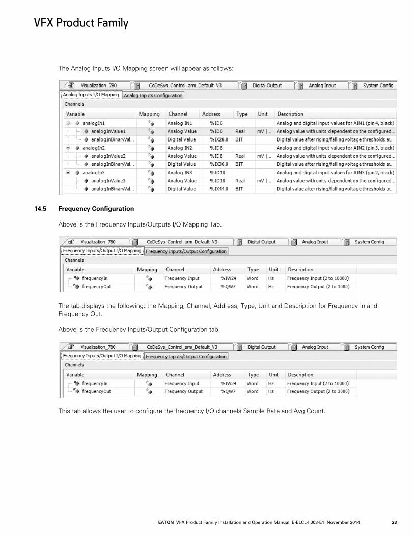
The Analog Inputs I/O Mapping screen will appear as follows:
14.5 Frequency Configuration
Above is the Frequency Inputs/Outputs I/O Mapping Tab.
The tab displays the following: the Mapping, Channel, Address, Type, Unit and Description for Frequency In and Frequency Out.
Above is the Frequency Inputs/Output Configuration tab.
This tab allows the user to configure the frequency I/O channels Sample Rate and Avg Count.
EATON VFX Product Family Installation and Operation Manual E-ELCL-II003-E1 October 201424
VFX Product Family
14.6 CAN & SAE J1939
• Each device added to the J1939 manager represents a physical device on the bus. • So a "local device" represents the local mobile controller. This is
the message the controller will be *transmitting*. See the "local device" checkbox in the general tab.
• A non-"local device" represents a physical device on the bus. Thus its "Tx Signals" are what the device is sending and the mobile controller is received.
• Thus you should generally add one "device" to the tree to represent each device that is on the physical bus, including the "local" device.
• Also make sure you have the "local device" checked for the node that you want to be transmitting signals. While this is not intuitive at first, it makes complete sense once you are aware of it.
• There are no function blocks and everything happens automatically in the background. You just get scaled variables you can read or write from code.
• All transmission happens automatically per the configuration for each PGN. The "TransmissionMode" tab specifies the interval. Relevant options are "Change of State" and "Cyclic", but the default is change of state so the packet will not be sent unless one of the variables changes (i.e. from your code). Cyclic is the more traditional J1939 method and better for testing.
• The "I/O" mapping tab represents all the variables available in the device. These can be used in code for either inputs or outputs depending on whether it is a transmitted or received packet.
• You can automatically convert and scale variables by clicking on the SPN in the "Tx Signals" page, and then enabling the "Conversion" option. This lets you deal in engineering units (i.e. %, rpm, mph, etc) as opposed to the raw data bytes.
• Variables in the I/O mapping tab will not be updated unless physically used in code. This is an optimization done by the 3S compiler to reduce computation for unused variables. For debugging, you can check the "Always update variables" box and it will instruct the compiler/debugger to always display and update the values.
• The CAN "Network" option is base-zero. Thus Network 0 represents the first CAN bus, Network 1 represents the second CAN bus, and Network 2 represents the third.
EATON VFX Product Family Installation and Operation Manual E-ELCL-II003-E1 November 2014 25
15.0 APPENDIX
15.1 Supported & Unsupported CODESYS Features
Since CODESYS is a generic broad-based software environment that supports a multitude of different products, not all features are relevant with a given product. In the case of our VFX series displays, the following list indicates features that are and are not supported:
Supported
1. Debug variable viewing
2. Login
3. Logout
4. Download (single application)
5. Run
6. Stop
7. Reset (warm, cold, origin)
8. Logger
9. Files and directories (24KB max storage and 16 character names or directories)
10. Write values
11. Create boot application
12. Visualization
13. Task monitor
14. Remanent variables
15. Task Timing – cyclic, freewheeling, event, status
16. Dynamic IO configuration.
17. Debug > display mode
18. Simulation
19. IEC task watchdog
20. IEC 61131-3 programming languages
21. Microsecond time resolution
22. Force/unforce
Not supported
1. Show call stack
2. Display flow stack
3. PLC shell
4. Users and groups
5. Access rights
6. Source download
7. Data server
8. Alarm manager
9. Text editor
10. Path3D
11. Cam displayer
12. Task timing – external event
VFX Product Family
EATON VFX Product Family Installation and Operation Manual E-ELCL-II003-E1 October 201426
VFX Product Family
16.0 DEVICE COMMUNICATION TROUBLESHOOTING
The following is a list of things to check, in order of priority, if you are having problems connecting to your display from Pro-FX Control.
1. Make sure the device is powered up.
2. Make sure the USB port is connected, and Win-dows has properly loaded the drivers.
3. Make sure that the gateway.cfg file has been properly installed per the instructions in this document. Installation of a non-approved device gateway may have overwritten this file.
4. In the Pro-FX Control Communication Settings, select None for the Filter. Then rescan for the de-vice. If something new appears, then it could be that the device variant being used by your project is different than the connected device. Pro-FX Control will only let you connect to a device vari-ant that matches the configuration of your project. To switch to the appropriate device, right click on it in the Devices project tree and select Update Device.
5. Stop and start the gateway. Plug and unplug the USB port.
6. Restart Pro-FX Control.
7. Restart your PC.
8. In some cases, Windows will automatically assign a high COM port number to the USB device. If the device manager shows something higher than COM20 then you should reassign it to some-thing lower. Then restart the gateway and unplug and plug the USB port.
9. Each time a unique device is connected to your PC, Windows will provide two new COM port numbers. In some cases, Pro-FX Control appears to have problems automatically discovering the device's COM port when the value gets too high. In this case, there are two options:
• From the device manager, click the COM port's properties, select Port Settings tab, click Advanced and select a Com Port Number that is below COM20. Then restart the gateway and replug the USB device to ensure changes are applied properly.
• You can alternately edit the gateway.cfg to manually assign your device's COM port number. Open the gateway.cfg file located in the Pro-FX Control install directory, and change the line that begins with Com.0.Port. After making this change, restart the gateway. Note: After making this change, your installation will no longer automatically detect other displays so this must be repeated for all unique displays that are connected to your PC.

© 2014 EatonAll Rights ReservedPrinted in USADocument No. E-ELCL-II003-E1November 2014
EatonHydraulics Group USA14615 Lone Oak RoadEden Prairie, MN 55344USATel: 952-937-9800Fax: 952-294-7722www.eaton.com/hydraulics
EatonHydraulics Group EuropeRoute de la Longeraie 71110 MorgesSwitzerlandTel: +41 (0) 21 811 4600Fax: +41 (0) 21 811 4601
EatonHydraulics Group Asia PacificEaton BuildingNo.7 Lane 280 Linhong RoadChangning District,Shanghai 200335ChinaTel: (+86 21) 5200 0099Fax: (+86 21) 2230 7240