Embed Size (px)
DESCRIPTION
fujitsu siemens
Citation preview

Fujitsu LifeBook®
P1610 Notebook
User’s Guide
P Series.book Page 1 Monday, October 9, 2006 10:58 AM

P Series.book Page 2 Monday, October 9, 2006 10:58 AM

C o p y r i g h t
Copyright & Trademark Information
Fujitsu Computer Systems Corporation has made every effort to ensure the accuracy and completeness of this document. However, as ongoing development efforts are continually improving the capabilities of our products, we cannot guarantee the accuracy of the contents of this document. We disclaim liability for errors, omissions, or future changes.
Fujitsu, the Fujitsu logo, and LifeBook are registered trademarks of Fujitsu Limited.
Microsoft, MS-DOS, and Windows are either registered trademarks or trademarks of Microsoft Corporation in the United States and/or other countries.
PCMCIA is a trademark of the Personal Computer Memory Card International Association.
Centrino, Intel, and Intel Core are trademarks or registered trademarks of Intel Corporation or its subsidiaries in the United States and other countries.
OmniPass is a trademark of Softex, Inc.
Atheros and Super AG are registered trademarks of Atheros Communications, Inc.
Adobe, Acrobat, and Acrobat Reader are either regis-tered trademarks or trademarks of Adobe Systems Incorporated in the United States and/or other coun-tries.
Realtek is a trademark of Realtek Semiconductor Corpo-ration.
Bluetooth is a registered trademark of Bluetooth SIG, Inc.
All other trademarks mentioned herein are the property of their respective owners.
© Copyright 2006 Fujitsu Computer Systems Corpora-tion. All rights reserved. No part of this publication may be copied, reproduced, or translated, without prior written consent of Fujitsu Computer Systems Corpora-tion. No part of this publication may be stored or trans-mitted in any electronic form without the written consent of Fujitsu Computer Systems Corporation.
B5FJ-1131-01EN-00
WARNING
Handling the cord on this product or cords associated with accessories sold with this product, will expose you to lead, a chemical known to the State of California to cause birth defects or other reproductive harm.
Wash hands after handling.
DECLARATION OF CONFORMITYaccording to FCC Part 15
Responsible Party Name: Fujitsu Computer Systems Corporation
Address: 1250 E. Arques Avenue, MS 122Sunnyvale, CA 94085
Telephone: (408) 746-6000
Declares that product: Model Configuration: LifeBook P1610 NotebookComplies with Part 15 of the FCC Rules.
This device complies with Part 15 of the FCC rules. Operations are subject to the following two conditions:(1) This device may not cause harmful interference, (2) This device must accept any interference received, including interference that may cause undesired operation.
P Series.book Page 3 Monday, October 9, 2006 10:58 AM

L i f e B o o k P 1 6 0 0 S e r i e s N o t e b o o k
IMPORTANT SAFETY INSTRUCTIONS This unit requires an AC adapter to operate. Use only UL Listed I.T.E. Adapters with an output rating of 16 VDC, with a minimum current of 2.5 A.
AC adapter output polarity:
When using your notebook, basic safety precautions should always be followed to reduce the risk of fire, elec-tric shock and injury to persons, including the following:
■ Do not use this product near water for example, near a bathtub, washbowl, kitchen sink or laundry tub, in a wet basement or near a swimming pool.
■ Avoid using the modem during an electrical storm. There may be a remote risk of electric shock from lightning.
■ Do not use the modem to report a gas leak in the vicinity of the leak.
■ Use only the power cord and batteries indicated in this manual. Do not dispose of batteries in a fire. They may explode. Check with local codes for possible special disposal instructions.
■ To reduce the risk of fire, use only No. 26 AWG or larger UL Listed or CSA Certified Telecommunica-tion Line Cord.
■ For TV Tuner Models: To protect from overvoltages and transients on the Cable Distribution System, make sure that the outer shield of the coaxial cable is con-nected to earth (grounded) at the building premises as close to the point of cable entrance as practicable, as required per NEC Article 820.93, ANSI/NFPA 70: 2005. If you have questions about your CATV installa-tion, contact your service provider.
SAVE THESE INSTRUCTIONS
For Authorized Repair Technicians Only
+
Danger of explosion if Lithium (clock) bat-tery is incorrectly replaced. Replace only with the same or equivalent type recom-mended by the manufacturer. Dispose of used batteries according to the manufac-turer’s instruction.
For continued protection against risk of fire, replace only with the same type and rating fuse.
P Series.book Page 4 Monday, October 9, 2006 10:58 AM

T a b l e o f C o n t e n t s
Fujitsu LifeBook® P1600 Series Notebook
Table of Contents
1PREFACE
PrefaceAbout This Guide . . . . . . . . . . . . . . . . . . . . . . . . .3Fujitsu Contact Information . . . . . . . . . . . . . . . . .3Warranty . . . . . . . . . . . . . . . . . . . . . . . . . . . . . . .3
2GETTING TO KNOWYOUR LIFEBOOK
OverviewUnpacking . . . . . . . . . . . . . . . . . . . . . . . . . . . . . .7Optional Accessories . . . . . . . . . . . . . . . . . . . . . .7
Locating Controls and ConnectorsFront and Display Components . . . . . . . . . . . . . .9Left-Side Panel Components . . . . . . . . . . . . . . .10Right-Side Panel Components . . . . . . . . . . . . . .11Rear Panel Components . . . . . . . . . . . . . . . . . . .12Bottom Components . . . . . . . . . . . . . . . . . . . . .13
Status IndicatorsPower Indicator . . . . . . . . . . . . . . . . . . . . . . . . .14Battery Level Indicator . . . . . . . . . . . . . . . . . . . .14Hard Drive Access Indicator . . . . . . . . . . . . . . . .14NumLk Indicator. . . . . . . . . . . . . . . . . . . . . . . . .14CapsLock Indicator . . . . . . . . . . . . . . . . . . . . . . .14ScrLk Indicator . . . . . . . . . . . . . . . . . . . . . . . . . .14
Display PanelOpening the Display Panel . . . . . . . . . . . . . . . . .15Using the System as a Tablet . . . . . . . . . . . . . . .15Adjusting Display Panel Brightness . . . . . . . . . . .16
KeyboardUsing the Keyboard . . . . . . . . . . . . . . . . . . . . . .17Numeric Keypad. . . . . . . . . . . . . . . . . . . . . . . . .17Windows Keys . . . . . . . . . . . . . . . . . . . . . . . . . .17Cursor Keys . . . . . . . . . . . . . . . . . . . . . . . . . . . .17Function Keys. . . . . . . . . . . . . . . . . . . . . . . . . . .18
LifeBook Security/Application PanelSetting up Your LifeBook Security Panel . . . . . . .19Passwords . . . . . . . . . . . . . . . . . . . . . . . . . . . . .19Operating Your Security/ Application Panel . . . .20Precautions. . . . . . . . . . . . . . . . . . . . . . . . . . . . .20Uninstalling the Security Panel Application . . . . .20Using the Lifebook Application Panel . . . . . . . . .21Changing Button Functions . . . . . . . . . . . . . . . .23
Pointing Device/Touch ScreenClicking . . . . . . . . . . . . . . . . . . . . . . . . . . . . . . .24Double-Clicking . . . . . . . . . . . . . . . . . . . . . . . . .24Dragging . . . . . . . . . . . . . . . . . . . . . . . . . . . . . .24Quick Point Control Adjustment. . . . . . . . . . . . .25Touch Screen . . . . . . . . . . . . . . . . . . . . . . . . . . .25
Volume ControlControlling the Volume . . . . . . . . . . . . . . . . . . .27
3USING YOUR LIFEBOOK
Power SourcesConnecting the Power Adapters . . . . . . . . . . . . .31
Starting Your LifeBookPower On. . . . . . . . . . . . . . . . . . . . . . . . . . . . . .32Boot Sequence . . . . . . . . . . . . . . . . . . . . . . . . . .32BIOS Setup Utility. . . . . . . . . . . . . . . . . . . . . . . .32Booting the System . . . . . . . . . . . . . . . . . . . . . .33Registering Your Notebook . . . . . . . . . . . . . . . .33Installing Click Me! . . . . . . . . . . . . . . . . . . . . . .33
P Series.book Page 5 Monday, October 9, 2006 10:58 AM
L i f e B o o k P 1 6 0 0 S e r i e s N o t e b o o k
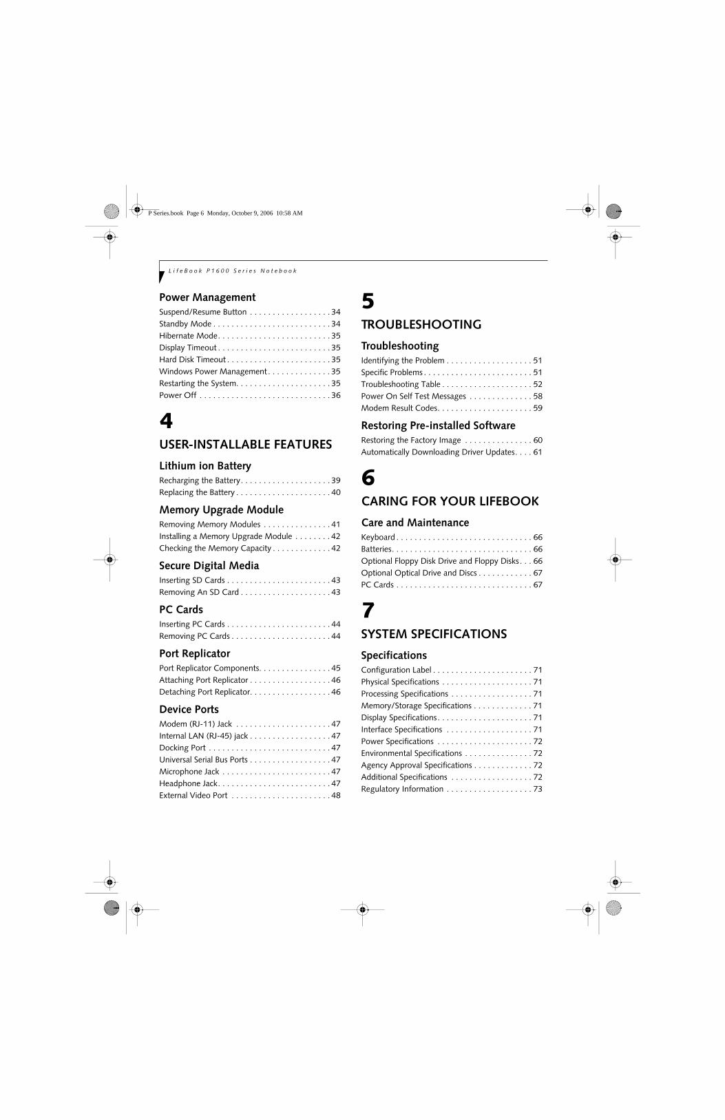
Power ManagementSuspend/Resume Button . . . . . . . . . . . . . . . . . . 34Standby Mode . . . . . . . . . . . . . . . . . . . . . . . . . . 34Hibernate Mode. . . . . . . . . . . . . . . . . . . . . . . . . 35Display Timeout . . . . . . . . . . . . . . . . . . . . . . . . . 35Hard Disk Timeout . . . . . . . . . . . . . . . . . . . . . . . 35Windows Power Management . . . . . . . . . . . . . . 35Restarting the System. . . . . . . . . . . . . . . . . . . . . 35Power Off . . . . . . . . . . . . . . . . . . . . . . . . . . . . . 36
4USER-INSTALLABLE FEATURES
Lithium ion BatteryRecharging the Battery. . . . . . . . . . . . . . . . . . . . 39Replacing the Battery . . . . . . . . . . . . . . . . . . . . . 40
Memory Upgrade ModuleRemoving Memory Modules . . . . . . . . . . . . . . . 41Installing a Memory Upgrade Module . . . . . . . . 42Checking the Memory Capacity . . . . . . . . . . . . . 42
Secure Digital MediaInserting SD Cards . . . . . . . . . . . . . . . . . . . . . . . 43Removing An SD Card . . . . . . . . . . . . . . . . . . . . 43
PC CardsInserting PC Cards . . . . . . . . . . . . . . . . . . . . . . . 44Removing PC Cards . . . . . . . . . . . . . . . . . . . . . . 44
Port ReplicatorPort Replicator Components. . . . . . . . . . . . . . . . 45Attaching Port Replicator . . . . . . . . . . . . . . . . . . 46Detaching Port Replicator. . . . . . . . . . . . . . . . . . 46
Device PortsModem (RJ-11) Jack . . . . . . . . . . . . . . . . . . . . . 47Internal LAN (RJ-45) jack . . . . . . . . . . . . . . . . . . 47Docking Port . . . . . . . . . . . . . . . . . . . . . . . . . . . 47Universal Serial Bus Ports . . . . . . . . . . . . . . . . . . 47Microphone Jack . . . . . . . . . . . . . . . . . . . . . . . . 47Headphone Jack. . . . . . . . . . . . . . . . . . . . . . . . . 47External Video Port . . . . . . . . . . . . . . . . . . . . . . 48
5TROUBLESHOOTING
TroubleshootingIdentifying the Problem . . . . . . . . . . . . . . . . . . . 51Specific Problems . . . . . . . . . . . . . . . . . . . . . . . . 51Troubleshooting Table . . . . . . . . . . . . . . . . . . . . 52Power On Self Test Messages . . . . . . . . . . . . . . 58Modem Result Codes. . . . . . . . . . . . . . . . . . . . . 59
Restoring Pre-installed SoftwareRestoring the Factory Image . . . . . . . . . . . . . . . 60Automatically Downloading Driver Updates. . . . 61
6CARING FOR YOUR LIFEBOOK
Care and MaintenanceKeyboard . . . . . . . . . . . . . . . . . . . . . . . . . . . . . . 66Batteries. . . . . . . . . . . . . . . . . . . . . . . . . . . . . . . 66Optional Floppy Disk Drive and Floppy Disks . . . 66Optional Optical Drive and Discs . . . . . . . . . . . . 67PC Cards . . . . . . . . . . . . . . . . . . . . . . . . . . . . . . 67
7SYSTEM SPECIFICATIONS
SpecificationsConfiguration Label . . . . . . . . . . . . . . . . . . . . . . 71Physical Specifications . . . . . . . . . . . . . . . . . . . . 71Processing Specifications . . . . . . . . . . . . . . . . . . 71Memory/Storage Specifications . . . . . . . . . . . . . 71Display Specifications. . . . . . . . . . . . . . . . . . . . . 71Interface Specifications . . . . . . . . . . . . . . . . . . . 71Power Specifications . . . . . . . . . . . . . . . . . . . . . 72Environmental Specifications . . . . . . . . . . . . . . . 72Agency Approval Specifications . . . . . . . . . . . . . 72Additional Specifications . . . . . . . . . . . . . . . . . . 72Regulatory Information . . . . . . . . . . . . . . . . . . . 73
P Series.book Page 6 Monday, October 9, 2006 10:58 AM

T a b l e o f C o n t e n t s
8GLOSSARYGlossary . . . . . . . . . . . . . . . . . . . . . . . . . . . . . . .77
APPENDIX A: INTEGRATED WIRELESS LAN USER’S GUIDE
Before Using the Wireless LANWireless LAN Modes Using this Device. . . . . . . .86Wireless Network Considerations . . . . . . . . . . . .87Deactivating the WLAN Device . . . . . . . . . . . . .87Activating the WLAN Device . . . . . . . . . . . . . . .88
Configuration of the WLAN DeviceFlow of Operations. . . . . . . . . . . . . . . . . . . . . . .89Configuration Using Intel PROSet Software . . . .89Configuration Using Atheros Client Utility . . . . .90Connection to the network. . . . . . . . . . . . . . . . .91
Troubleshooting the WLANTroubleshooting . . . . . . . . . . . . . . . . . . . . . . . . .95
Wireless LAN GlossaryGlossary . . . . . . . . . . . . . . . . . . . . . . . . . . . . . . .96
IP address informationAbout IP Addresses . . . . . . . . . . . . . . . . . . . . . .98
WLAN SpecificationsSpecifications . . . . . . . . . . . . . . . . . . . . . . . . . . .99
Using the Bluetooth DeviceWhat is Bluetooth. . . . . . . . . . . . . . . . . . . . . . .100Where to Find Information About Bluetooth . .100
APPENDIX B: USING THE FINGERPRINT SWIPE SENSOR
Fingerprint Sensor DeviceIntroducing the Fingerprint Sensor Device . . . .103Getting Started. . . . . . . . . . . . . . . . . . . . . . . . .103Installing OmniPass . . . . . . . . . . . . . . . . . . . . .103User Enrollment . . . . . . . . . . . . . . . . . . . . . . . .104Using OmniPass . . . . . . . . . . . . . . . . . . . . . . . .105Configuring OmniPass . . . . . . . . . . . . . . . . . . .107OmniPass Control Center . . . . . . . . . . . . . . . . .108Troubleshooting . . . . . . . . . . . . . . . . . . . . . . . .109
P Series.book Page 7 Monday, October 9, 2006 10:58 AM

L i f e B o o k P 1 6 0 0 S e r i e s N o t e b o o k
P Series.book Page 8 Monday, October 9, 2006 10:58 AM

1
1Preface
P Series.book Page 1 Monday, October 9, 2006 10:58 AM

2
L i f e B o o k P 1 6 0 0 S e r i e s N o t e b o o k
P Series.book Page 2 Monday, October 9, 2006 10:58 AM

3
P r e f a c e
Preface
ABOUT THIS GUIDEThe LifeBook® P1600 Series notebook from Fujitsu Computer Systems Corporation is a small yet powerful convertible computer. It can be used either as a standard notebook using keyboard input, or in tablet configura-tion using pen input. It is powered by an Intel® Core™ Solo processor and an integrated Intel 945 GMS graphics controller with 128 MB of graphics memory. The notebook has a built-in 8.9” TFT wide XGA color display.
This manual explains how to operate your LifeBook P1600 Series notebook’s hardware and built-in system software. Your notebook comes with the Microsoft® Windows® XP or Windows Tablet PC Edition 2005 operating system pre-installed.
Conventions Used in the GuideKeyboard keys appear in brackets. Example: [Fn], [F1], [Esc], [Enter] and [Ctrl].
Pages with additional information about a specific topic are cross-referenced within the text.Example: (See page xx.)
On screen buttons or menu items appear in bold.Example: Click OK to restart your notebook.
DOS commands you enter appear in Courier type. Example: Shutdown the computer?
FUJITSU CONTACT INFORMATIONService and SupportYou can contact Fujitsu Computer Systems Service and Support the following ways:
■ Toll free: 1-800-8Fujitsu (1-800-838-5487)■ Fax: 1-408-764-2724 ■ E-mail: [email protected] ■ Website: us.fujitsu.com/computers
Before you place the call, you should have the following information ready so that the customer support representative can provide you with the fastest possible solution:
■ Product name■ Product configuration number■ Product serial number■ Purchase date■ Conditions under which the problem occurred■ Any error messages that have occurred■ Type of device connected, if any
Fujitsu OnlineYou can go to the online Fujitsu Product catalog for your notebook by clicking on Start -> Fujitsu Weblinks -> LifeBook Accessories or by going to www.ShopFujitsu.com.
You can also reach Fujitsu Service and Support online by going to Start -> Fujitsu Weblinks -> Fujitsu Service and Support.
WARRANTYYour LifeBook P1600 Series notebook is backed by an International Limited Warranty and includes toll-free technical support. Check the service kit that came with your system for warranty terms and conditions.
The operating system installed on your computer determines whether your system is classified as a notebook or Tablet PC.
The information icon highlights information that will enhance your understanding of the subject material.
The caution icon highlights information that is important to the safe operation of your computer, or to the integrity of your files. Please read all caution information carefully.
The warning icon warns you about possible hazards that can occur to you, your system, or your files. Please read all warning information carefully.
You must have an active internet connection to use the online URL links.
P Series.book Page 3 Monday, October 9, 2006 10:58 AM

4
L i f e B o o k P 1 6 0 0 S e r i e s N o t e b o o k
P Series.book Page 4 Monday, October 9, 2006 10:58 AM

5
2Getting to KnowYour LifeBook
P Series.book Page 5 Monday, October 9, 2006 10:58 AM

6
L i f e B o o k P 1 6 0 0 S e r i e s N o t e b o o k
P Series.book Page 6 Monday, October 9, 2006 10:58 AM

7
G e t t i n g t o K n o w Y o u r L i f e B o o k
Figure 2-1. Fujitsu LifeBook P1600 series notebook
OverviewThis section describes the components of your Fujitsu LifeBook P1600 Series notebook. We strongly recom-mend that you read it before using your system, even if you are already familiar with mobile computers.
UNPACKINGWhen you receive your LifeBook P1600 Series notebook, unpack it carefully, and compare the parts you have received with the items listed below.
For a pre-configured model you should have:
■ LifeBook P1600 Series notebook (Figure 2-1)■ AC adapter with AC power cord (Figure 2-2)■ Phone/Modem (RJ-11) telephone cable■ Pen■ Driver and Application Restore (DAR) CD■ Recovery CD■ Getting Started Guide■ User’s Guide (this document)■ International Limited Warranty Booklet■ Certificate of Authenticity■ Lithium ion battery (pre-installed)
You may also have one or more of the following devices in the box, depending upon the configuration of your system:
■ Port Replicator (Figure 2-3)■ External USB Floppy Disk Drive■ Additional battery(s)■ Application CD(s) for third-party software
Figure 2-2. AC Adapter
Figure 2-3. Optional Port Replicator
OPTIONAL ACCESSORIES
A variety of optional accessories is available for use with your LifeBook P1600 Series notebook. For the latest list of accessories available, be sure to frequently check the Fujitsu website at: www.shopfujitsu.com. Refer to the instructions provided with these accessories for details on their use.
The operating system installed on your computer determines whether your system is classified as a notebook or Tablet PC.
P Series.book Page 7 Monday, October 9, 2006 10:58 AM

8
L i f e B o o k P 1 6 0 0 S e r i e s N o t e b o o k
Locating the Controls and ConnectorsConnectors and peripheral interfaces on the LifeBook P1600 Series notebook and the optional port replicator allow you to connect a variety of devices. Specific loca-tions are illustrated in Figures 2-4 through 2-8. The table
below provides a short description of each icon on the LifeBook P1600 Series notebook. Each of the icons is either molded into or printed on the system chassis.
Table 2-1. System icons
ConnectionLifeBook
IconPurpose
DC in connector Connect an external power source such as the AC adapter or auto/airline adapter.
Secure Digital (SD) Slot
The Secure Digital (SD) card slot allows you to install a flash memory card for data storage. Flash memory cards allow you to transfer data to and from a variety of different digital devices.
USB Ports Connect Universal Serial Bus 2.0 or 1.1 compliant devices to the notebook.
Microphone Jack Connect an external microphone. The internal microphone is disabled when you plug in an external microphone. The same icon is used for the internal microphone.
Fingerprint Sensor Use the fingerprint sensor to log onto the system using your fingerprint as the “password”.
Headphone Jack Connect stereo headphones or powered external speakers. The internal speaker is disabled when you plug in external headphones or powered speakers.
Modem Connect a telephone line to the internal modem using a standard RJ-11 telephone plug.
PCMCIA Card slot Insert a Type I or Type II PC Card.
Security lock slot The security slot allows you to secure the notebook using notebook locking devices.
Suspend/Resume button
The Suspend/Resume button allows you to suspend system activity without powering off, resume from suspend mode, and power on the system when it has been shut down from Windows.
Local Area Network (LAN)
The LAN (RJ-45) jack is used to connect the internal 10/100 Base-T/Tx Ethernet to a Local Area Network (LAN) in your office or home, or broadband devices such as a cable modem, DSL, or satellite Internet.
Battery Release Latch The battery release latch allows you to remove the battery from your system for storage or replacement.
Wireless LAN/Bluetooth On/Off Switch
The wireless LAN switch allows you to turn power to the optional wireless LAN or Bluetooth device on and off.
P Series.book Page 8 Monday, October 9, 2006 10:58 AM

9
G e t t i n g t o K n o w Y o u r L i f e B o o k
Figure 2-4. LifeBook P1600 Series notebook with display open
FRONT AND DISPLAY COMPONENTSThe following is a brief description of the front and display features of the LifeBook P1600 Series notebook. (Figure 2-4)
Display Panel LatchThe display panel latch holds the display panel in posi-tion.
Display PanelThe display panel is a color LCD panel with back lighting for the display of text and graphics and touch screen functionality.
Suspend/Resume ButtonThe Suspend/Resume button allows you to suspend system activity without powering off, resume your system from standby mode, and power on your system when it has been shut down from the Windows oper-ating system. See “Power On” on page 32.
Status Indicator PanelThe Status Indicator Panel displays symbols that corre-spond to specific components of your LifeBook P1600 Series notebook. See “Status Indicators” on page 14.
KeyboardA full-function keyboard with dedicated Windows keys. See “Keyboard” on page 17.
Quick Point Pointing DeviceThe Quick Point pointing device consists of two mouse-like buttons, one scroll button, and a cursor control button (located near the center of the keyboard). See “Quick Point Pointing Device/Touch Screen” on page 24.
SpeakerThe speaker allows you to listen to sound from your system.
LifeBook Security/Application ButtonsThe LifeBook P1600 Series notebook Security/Applica-tion Buttons provide application launch capabilities. See “LifeBook Security/ Application Panel” on page 19.
Fingerprint SensorThe fingerprint recognition sensor allows you to log into Windows or other applications by replacing your user-name and password. See “Fingerprint Sensor Device” on page 103.
Built-in MicrophoneThe built-in microphone allows you to input mono audio.
Display
Status
LifeBook Security/
IndicatorPanel
Panel
Display Panel Latch
Application
Suspend/ResumeButton
Built-in Microphone
Fingerprint Sensor
Panel Buttons
Quick Point
Keyboard
Pointing Device
Speaker
P Series.book Page 9 Monday, October 9, 2006 10:58 AM

10
L i f e B o o k P 1 6 0 0 S e r i e s N o t e b o o k
Figure 2-5. LifeBook P1600 Series notebook left-side panel
LEFT-SIDE PANEL COMPONENTSFollowing is a brief description of your notebook’s left-side components. (Figure 2-5)
WLAN/Bluetooth On/Off SwitchThe wireless LAN/Bluetooth On/Off Switch is used to power off the wireless devices when not in use.
PC Card SlotThe PC Card Slot allows you to insert a PCMCIA Card. The PC Card Eject Button is used when ejecting a PC Card from the slot. See “Inserting PC Cards” on page 44.
PC Card Slot
PC Card Eject Button
WLAN/Bluetooth On/Off Switch
P Series.book Page 10 Monday, October 9, 2006 10:58 AM

11
G e t t i n g t o K n o w Y o u r L i f e B o o k
Figure 2-6. LifeBook P1600 Series notebook right-side panel
RIGHT-SIDE PANEL COMPONENTSFollowing is a brief description of your notebook’s right-side components.
SD CardThe Secure Digital (SD) card slot allows you to insert a flash memory card for data storage. Flash memory cards allow you to transfer data to and from a variety of different digital devices.
Headphone JackThe headphone jack allows you to connect stereo head-phones or powered external speakers. See “Headphone Jack” on page 47.
Microphone JackThe microphone jack allows you to connect an external mono microphone. See “Microphone Jack” on page 47.
DC Power JackThe DC power jack allows you to plug in the AC adapter or the optional Auto/Airline adapter to power your system and charge the internal Lithium ion Battery.
USB 2.0 PortsThe USB 2.0 ports allow you to connect Universal Serial Bus devices. See “Universal Serial Bus Ports” on page 47.
Pen/Pen HolderThe pen is used as the interface with the digitizer display.
USB 2.0 Ports
Secure Digital (SD) Card Slot
Pen/Pen Holder DC Power Jack
Headphone Jack Microphone Jack
P Series.book Page 11 Monday, October 9, 2006 10:58 AM

12
L i f e B o o k P 1 6 0 0 S e r i e s N o t e b o o k
Figure 2-7. LifeBook P1600 Series notebook rear panel
REAR PANEL COMPONENTS
External Video PortThe external video port allows you to connect an external CRT monitor or LCD projector. Note that when the optional Port Replicator is attached to the system, you must use the external video port on the Port Repli-cator rather than the port on the system. See “External Video Port” on page 48.
LAN (RJ-45) PortThe internal LAN (RJ-45) port is used for an internal 10/100/1000 Base-Tx Ethernet. See “Internal LAN (RJ-45) jack” on page 47.
Modem (RJ-11) Telephone PortThe Modem (RJ-11) telephone port is for attachinga telephone line to the internal multinational 56K modem.
Anti-theft Lock SlotThe anti-theft lock slot allows you to attach a optional physical lock-down device.
Air VentsThe air vents allow proper air circulation to ensure that the system does not overheat.
External Video Port (behind cover)
LAN (RJ-45) Port
Modem
Air Vents
Anti-theft
(RJ-11) Port
Lock Slot
The internal multinational modem is not intended for use with Digital PBX systems. Do not connect the internal modem to a Digital PBX as it may cause serious damage to the internal modem or your entire LifeBook P1600 Series notebook. Consult your PBX manufacturer’s documentation for details. Some hotels have Digital PBX systems. Be sure to find out BEFORE you connect your modem.
The internal modem is designed to the ITU-T V.90 standard. Its maximum speed of 53000 bps is the highest allowed by FCC, and its actual connection rate depends on the line conditions. The maximum speed is 33600 bps at upload.
To protect your notebook from damage and to optimize system performance, be sure to keep all air all vents unobstructed, clean, and clear of debris. This may require periodic cleaning, depending upon the environment in which the system is used.
Do not operate the notebook in areas where the air vents can be obstructed, such as in tight enclosures or on soft surfaces like a bed or cushion.
P Series.book Page 12 Monday, October 9, 2006 10:58 AM

13
G e t t i n g t o K n o w Y o u r L i f e B o o k
Figure 2-8. LifeBook P1600 Series notebook bottom panel
BOTTOM COMPONENTSFollowing is a brief description of your notebook’s bottom panel components. (Figure 2-8)
Battery Pack LatchesThe battery pack latches are used to lock the Lithium ion battery pack into the battery compartment.
Lithium ion BatteryThe battery compartment contains the internal Lithium ion battery. The battery should be removed when the computer is stored over a long period of time or for swapping a discharged battery with a charged Lithium ion battery. See “Lithium ion Battery” on page 39.
Air VentsThe air vents allow proper air circulation to ensure that the system does not overheat.
Memory Upgrade CompartmentYour notebook comes with high speed DDR2 Synchro-nous Dynamic RAM (SDRAM). The memory upgrade compartment allows you to expand the system memory capacity of your system, hence improving overall perfor-mance. See “Memory Upgrade Module” on page 41.
Port Replicator ConnectorThis connector allows you to connect the optional port replicator.
Main Unit and Configuration LabelThe configuration label shows the model number and other information about your LifeBook P1600 Series notebook. In addition, the configuration portion of the label has the serial number and manufacturer informa-tion that you will need to give your support representa-tive. It identifies the exact version of various components of your system.
Memory
Lithium ionBattery
Main Unit andConfiguration
Label (approximate Port ReplicatorConnectorlocation)
Battery Pack Latches
UpgradeCompartment
Air Vents
To protect your system from damage and to optimize system performance, be sure to keep all air all vents unobstructed, clean, and clear of debris. This may require periodic cleaning, depending upon the environment in which the system is used.
Do not operate the system in areas where the air vents can be obstructed, such as in tight enclosures or on soft surfaces like a bed or cushion.
P Series.book Page 13 Monday, October 9, 2006 10:58 AM
14
L i f e B o o k P 1 6 0 0 S e r i e s N o t e b o o k
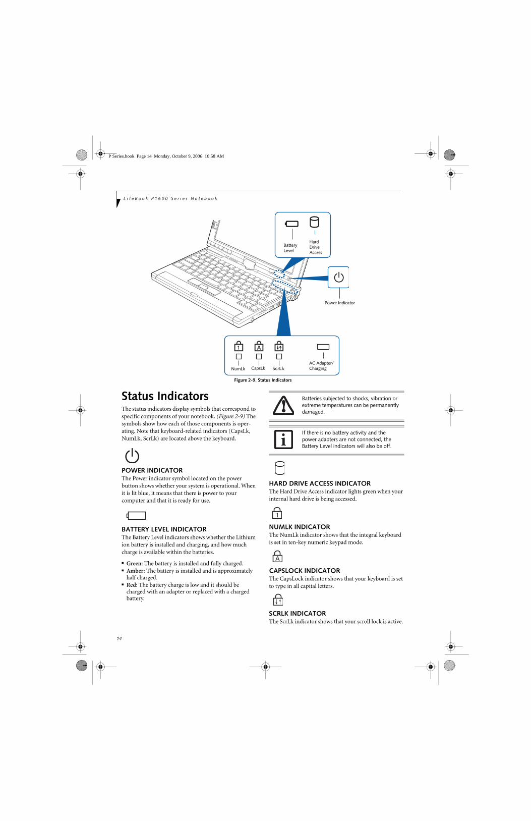
Figure 2-9. Status Indicators
Status IndicatorsThe status indicators display symbols that correspond to specific components of your notebook. (Figure 2-9) The symbols show how each of those components is oper-ating. Note that keyboard-related indicators (CapsLk, NumLk, ScrLk) are located above the keyboard.
POWER INDICATORThe Power indicator symbol located on the power button shows whether your system is operational. When it is lit blue, it means that there is power to your computer and that it is ready for use.
BATTERY LEVEL INDICATORThe Battery Level indicators shows whether the Lithium ion battery is installed and charging, and how much charge is available within the batteries.
■ Green: The battery is installed and fully charged.■ Amber: The battery is installed and is approximately
half charged.■ Red: The battery charge is low and it should be
charged with an adapter or replaced with a charged battery.
HARD DRIVE ACCESS INDICATORThe Hard Drive Access indicator lights green when your internal hard drive is being accessed.
NUMLK INDICATORThe NumLk indicator shows that the integral keyboard is set in ten-key numeric keypad mode.
CAPSLOCK INDICATORThe CapsLock indicator shows that your keyboard is set to type in all capital letters.
SCRLK INDICATORThe ScrLk indicator shows that your scroll lock is active.
Battery Hard
NumLk ScrLkCapsLkAC Adapter/Charging
LevelDrive Access
Power Indicator
Batteries subjected to shocks, vibration or extreme temperatures can be permanently damaged.
If there is no battery activity and the power adapters are not connected, the Battery Level indicators will also be off.
P Series.book Page 14 Monday, October 9, 2006 10:58 AM

15
G e t t i n g t o K n o w Y o u r L i f e B o o k
Figure 2-10. Opening the display
Display PanelThe convertible design of your LifeBook P1600 Series notebook allows you to open the display fully, rotate it 180 degrees in either direction, and lay it face up on the keyboard. This allows you to use the system as a tablet, much as you would a pad of paper.
OPENING THE DISPLAY PANELLift the display cover backwards, being careful not to touch the screen, until it is at a comfortable viewing angle. (Figure 2-10)
USING THE SYSTEM AS A TABLETIf you would like to use the system as a tablet, perform the following steps.
1. Lift the display until it is perpendicular to the keyboard. (Figure 2-12).
2. When the display is perpendicular to the keyboard, rotate it 180 degrees in either direction so that it is facing backwards. (Figure 2-13)
3. Holding the top edge of the display panel, pull it forward until it is lying nearly atop the keyboard.
4. Push the latch towards the display (See “A” in Figure 2-11). The latch will click twice and the top latch disappears, and the bottom latch appears (See “B” in Figure 2-11). Lay the display flush against the
system so that the latch rests in the slot in the battery pack. You can now use the system as a tablet. (Figure 2-15)
Figure 2-11. Using the Display Latch
5. To return the system to notebook configuration, repeat step 3 and 2. Be sure to turn the display in the opposite direction when performing step 2.
Figure 2-12. Fully open display
Display Cover
Latch Slot
Latch
Rotate the system display only in the direction indicated in the procedure. Turning the display in the incorrect direction could damage the hinge.
In the following step, be sure to position the display perpendicular to the keyboard, otherwise the keyboard or display cover could get scratched.
A
B
Top latch
Bottom latch
Display Side
P Series.book Page 15 Monday, October 9, 2006 10:58 AM

16
L i f e B o o k P 1 6 0 0 S e r i e s N o t e b o o k
Display Orientations in Tablet ConfigurationThe display orientations are limited to two positions: landscape and portrait, as indicated inFigure 2-15.
Figure 2-13. Rotating the display
Figure 2-14. Entering tablet configuration
Figure 2-15. System in tablet configuration
ADJUSTING DISPLAY PANEL BRIGHTNESSOnce you have turned on your system, you may want to adjust the brightness level of the screen to a more comfortable viewing level. There are three ways to adjust the brightness, keyboard, power management utility, and Fujitsu menu.
Using Keyboard to Adjust BrightnessAdjusting the brightness using the keyboard changes the system setting (i.e., the settings you make via the func-tion keys automatically changes the brightness settings in the system’s Brightness Control settings).
■ [Fn+F6]: Pressing repeatedly will lower the brightness of your display.
■ [Fn+F7]: Pressing repeatedly will increase thebrightness of the display.
Using Control Panel to Adjust BrightnessWindows XP Pro:To adjust brightness with the power management utility, click Start -> Control Panel -> Brightness Control. Set the screen brightness slider for battery and AC power scenarios.
Windows XP Tablet PC EditionTo adjust brightness with the Tablet and Pen Settings utility, click Start -> Control Panel -> Tablet and Pen Settings, then select the Display tab.
Using the Fujitsu Menu to Adjust BrightnessTo adjust brightness using the Fujitsu menu, click on the Fujitsu Menu icon in the system tray in the lower right corner of the screen. From the menu that appears, select Brightness Control. The Brightness Control window will open. Set the screen brightness slider for battery and AC power scenarios.
Landscape
Portraitorientation
orientation If using AC power, your brightness setting is set to its highest level by default. If using battery power your brightness settings is set to approximately mid-level by default.
The higher the brightness level, the more power the LifeBook P1600 Series notebook will consume and the faster your batteries will discharge. For maximum battery life, make sure that the brightness is set as low as possible.
P Series.book Page 16 Monday, October 9, 2006 10:58 AM

17
G e t t i n g t o K n o w Y o u r L i f e B o o k
Figure 2-16. Keyboard
Keyboard
USING THE KEYBOARDYour LifeBook P1600 Series notebook has an integral 82-key keyboard. The keys perform all the standard functions of a 101-key keyboard, including the Windows keys and other special function keys. This section describes the following keys. (Figure 2-16)
■ Numeric keypad: Your system allows certain keys to serve dual purposes, both as standard characters and as numeric and mathematical keys. The ability to tog-gle between the standard character and numerical keys is controlled through the [NumLk] key.
■ Cursor keys: Your keyboard contains four arrowkeys for moving the cursor or insertion point to the right, left, up, or down within windows, applications and documents.
■ Function keys: The keys labeled [F1] through [F12], are used in conjunction with the [Fn] key to produce special actions that vary depending on what program is running.
■ Windows keys: These keys work with your Windows operating system and function the same as the onscreen Start menu button, or the right button on your pointing device.
NUMERIC KEYPADCertain keys on the keyboard perform dual functions as both standard character keys and numeric keypad keys. NumLk can be activated by pressing the [NumLk] key. Turning off the NumLk feature is done the same way. Once this feature is activated you can enter numerals 0 through 9, perform addition ( + ), subtraction ( - ),multiplication ( * ), or division ( / ), and enter decimal points ( . ) using the keys designated as ten-key function keys. The keys in the numeric keypad are marked on the front edge of the key to indicate their secondary func-tions. (Figure 2-16)
WINDOWS KEYSYour LifeBook P1600 Series notebook has two Windows keys: a Start key and an Application key. The Start key displays the Start menu. This button functions the same as your onscreen Start menu button. The Application key functions the same as your right mouse button and displays shortcut menus for the selected item. (Please refer to your Windows documentation for additional information regarding the Windows keys.) (Figure 2-16)
CURSOR KEYSThe cursor keys are the four arrow keys on the keyboard which allow you to move the cursor up, down, left, and right in applications. In programs such as Windows Explorer, it moves the “focus” (selects the next item up, down, left, or right). (Figure 2-16)
Back Space
Fn Key Start Key
Function Keys
Numeric Keypad
Application Key Cursor Keys(outlined with thickblack line)
P Series.book Page 17 Monday, October 9, 2006 10:58 AM

18
L i f e B o o k P 1 6 0 0 S e r i e s N o t e b o o k
FUNCTION KEYSYour system has 12 function keys, F1 through F12. The functions assigned to these keys differ for each applica-tion. You should refer to your software documentation to find out how these keys are used. (Figure 2-16)
[Fn] KeyThe [Fn] key provides extended functions for thenotebook and is always used in conjunction with another key.
■ [Fn+F3]: Pressing [F3] while holding [Fn] will toggle the Audio Mute on and off.
■ [Fn+F4]: Pressing [F4] while holding [Fn] will toggle the built-in pointing device on and off. Note that the [Fn+F4] combination only works if Manual Setting is selected in the BIOS. (See “Entering the BIOS Setup Utility” on page 32)
■ [Fn +F5]: Pressing [F5] while holding [Fn] allows you to toggle between video compensation and no compensation. (Video compensation controls spacing on the display. When it is enabled, displays with less than 1024 x 600 or 800 x 600 pixel resolution will still cover the entire screen.)
■ [Fn+F6]: Pressing [F6] repeatedly while holding [Fn] will lower the brightness of your display. Note that adjusting the brightness using the keyboard changes the system setting.
■ [Fn+F7]: Pressing [F7] repeatedly while holding [Fn] will increase the brightness of the display.
■ [Fn+F8]: Pressing [F8] repeatedly while holding [Fn] will decrease the volume of your system.
■ [Fn+F9]: Pressing [F9] repeatedly while holding [Fn] will increase the volume of your system.
■ [Fn+F10]: Pressing [F10] while holding [Fn] allows you to change your selection of where to send your display video. Each time you press the combination of keys you will step to the next choice. The choices, in order, are: built-in display panel only, external moni-tor only, and both built-in display panel and external monitor.
P Series.book Page 18 Monday, October 9, 2006 10:58 AM

19
G e t t i n g t o K n o w Y o u r L i f e B o o k
Figure 2-17. LifeBook P1600 Series notebook application buttons
LifeBook Security/Application PanelA unique feature of your LifeBook notebook is the Secu-rity/Application Panel that allows you to secure your notebook from unauthorized use. The Security/Applica-tion Panel also allows you to launch applications with the touch of a button when your system is on.
If the security system is activated, upon starting your notebook or resuming from Standby mode the security system requires you to enter a password code using the buttons on the Security/Application Panel. After entering a correct password, your notebook resumes system operation. (Figure 2-17)
SETTING UP YOUR LIFEBOOK SECURITY PANELWhen you receive your LifeBook notebook, the security panel application is pre-installed without any pass-words. The following sections provide detailed informa-tion on your security panel, how to set, change or remove passwords.
Numbered ButtonsUse these buttons to enter your password.
Enter ButtonAfter entering the button strokes, push this button to enter the password into the LifeBook notebook.
PASSWORDSThe user and supervisor password may be set on this notebook. A supervisor password is typically the same for all LifeBook notebooks in a working group, office, or company to allow for system management. Individual
LifeBook notebooks in a group environment should not use a common password. A password consists of one to five button strokes plus the enter button. A valid stroke consists of pushing one or up to four buttons simulta-neously. The following are valid button strokes:
■ Pushing [4] by itself■ Pushing [2] and [3] at the same time■ Pushing [1], [2], and [4] at the same time■ Pushing [1], [2], [3], and [4] at the same time
The following are valid passwords. The numberswithin braces ({ }) are button strokes using morethan one button.
■ {[2]+[3]}, [1], [enter]■ [4], [enter]■ {[1]+[3]}, {[2]+[3]+[4]}, [1], [4], [2], [enter]
Setting PasswordsWhen shipped from the factory, no passwords are set. You have a choice of having no password or setting a supervisor and user password. You must set the super-visor password before the user password.
Setting Supervisor PasswordYou must have set a supervisor password before setting any user passwords. The supervisor password can bypass the user password.
Button 1/Application A/
Button 2/Application B/ Button 4/Function Button
Enter Button/Ctl-Alt-Del
Button 3/Screen Rotation
Backlight/Application C Button
Page Down
Page Up
■ The purpose of supervisor password is to be able to bypass the user password in case the user password is forgotten. The supervisor password alone will not lock the system.
■ You have to set both the supervisor and user passwords for the security panel to work.
P Series.book Page 19 Monday, October 9, 2006 10:58 AM

20
L i f e B o o k P 1 6 0 0 S e r i e s N o t e b o o k
1. Go to the Start menu.
2. Click on Run.
3. Type in:C:\Program Files\Fujitsu\Security Panel Application\Supervisor\FJSECS.EXE, then press [Enter]
4. Follow the on-screen instructions to set theSupervisor password.
Setting User Password1 Go to the Start menu.
2. Click on Programs.
3. Click on Security Panel Application andSet User Password.
4. Follow the on-screen instructions to set theuser password.
OPERATING YOUR LIFEBOOK SECURITY/ APPLICATION PANELThe security lock feature is in effect both when the system resumes from Off or Standby state. You always need to push the Suspend /Resume button to input the user pass-word. Your system will not begin the boot sequence without entering your supervisor/user password.
From Off State1. Turn on your system.
2. When the Security Indicator flashes, enter the pass-word and press Enter button.
For example, if the password is 22222,Press Button Number 2 five times and press Enter button.
The LifeBook notebook will boot to normal opera-tion.
From Standby State1. Press your Suspend/Resume button.
2. When the Security Indicator flashes, enter the pass-word and press Enter button.
The notebook should resume normal operation.
Incorrect Password EntryIf an invalid supervisor or user password is entered three times in succession, the system will “beep” for about one minute. If a valid password is entered within a minute (while system beeps), the beeping will stop and the note-book will resume normal operation. If no or an invalid password is entered while the system beeps, the system
will return to its previous locked state (standby or off) and the Security Indicator will go off. To reactivate the notebook after a password failure, you must press the Suspend/Resume button, then enter a correct password.
PRECAUTIONSOpening and Closing the CoverClosing the cover automatically places the notebook into Standby mode. Opening the cover does not automati-cally place the notebook into normal operation. Instead, you must enter the proper security password after pushing the Suspend/Resume button.
Low Battery OperationsIf your LifeBook notebook has low battery, pushing the suspend/resume button only turns on the Security Indi-cator. Your notebook does not unlock, the Security Indi-cator turns off after one minute. To resume normal operation, first attach a power supply to the notebook. Then you may unlock the notebook.
UNINSTALLING THE SECURITY PANEL APPLICATIONYou have two options when uninstalling the securitypanel application:
■ Uninstall the security panel application software.This will disable all security feature.
■ Uninstall the security panel application with password still active. This will not allow any changes to the password.
Uninstalling the Security Panel Application SoftwareRemove passwords when User wants no password protection whatsoever and doesn’t want to give anybody the utility to set a password on their computer. In this case, if passwords (supervisor, user, or both) are set, the passwords must first be cleared before removing the application. To clear passwords, follow same procedure in setting the passwords, except this time, check the “Remove Supervisor (and/or) User Password” box, as appropriate. Click [Next]. Enter the password. When asked to confirm that you want to remove the password, click [OK], then click [Finish].
You may change or remove the supervisor or user password by repeating the steps defined above.
Remember the user password you specified on the Security Panel Application. If you forget the password you will not be able to use your computer. The supervisor password can override the user password.
P Series.book Page 20 Monday, October 9, 2006 10:58 AM

21
G e t t i n g t o K n o w Y o u r L i f e B o o k
Removing Security Panel Application withPasswords Still ActiveUsing this feature will not allow any changes tothe password.
User: 1. Go to Start Menu, Click on Control Panel.
2. Open Add/Remove Programs Properties in the Control Panel.
3. Select the Security Panel Application in the list, and click Add/Remove.
4. When the Confirm File Deletion box appears,click Yes.
Supervisor:1. Go to Start Menu, Click on Control Panel.
2. Open Add/Remove Programs Properties in the Control Panel.
3. Select the Security Panel Application forSupervisor in the list, and click Add/Remove.
4. When the Confirm File Deletion box appears,click Yes.
Reinstalling the Security/Application PanelTo reinstall supervisor or user security application, you will need your Drivers and Applications CD. The Utilities\Security Application Panel folder contains two separate folders: Supervisor and User. The setup files for supervisor and user security applications are contained in those folders.
1. Go to the Utilities\Security Application Panel\Supervisor folder on the CD and double-click the setups.exe file. The Installing Security Panel Application window will appear. Follow the instruc-tions on the screen.
2. Go to the Utilities\Security Application Panel\User folder on the CD and double-click the setup.exe file. The Installing Security Panel Application window will appear. Follow the instructions on the screen.
Supervisor and user passwords can be set via Windows software using the FJSECS.exe and FJSECU.exe files, respectively. FJSECU.exe for the user password cannot run without first setting a supervisor password. You need to run FJSECS.exe first to set the supervisor pass-word. Follow instructions under Setting Passwords on page 19.
If you forget both passwords, please contact Fujitsu Computer Systems Service and Support at 1-800-8FUJITSU (1-800-838-5487). Fujitsu Computer Systems Corporation charges a service fee for unlocking a pass-word restricted LifeBook notebook. When calling please have a valid credit card and provide proof of ownership. You will then be given instructions on where to ship your notebook.
USING THE LIFEBOOK APPLICATION PANELFive application buttons are located on the bottom left-hand side of the display and when it is configured to be used as a notebook. (Figure 2-17) One additional button is located on the right-hand side of the displayadjacent to the battery indicator.
All six of the buttons have primary functions. Five of the buttons have secondary functions when used as applica-tion buttons. The secondary functions are activated by pressing the Function (Fn) button while pressing the application button. See Table 2-2 for specific functions. The secondary functions of the Application A and B buttons can be changed to launch any application. See “Changing Button Functions” on page 23.
Page Down / Application A ButtonWhen you press the Page Down button when the system is running, each press of the button will scroll the screen down one frame. This allows you to navigate quickly through large documents.
When you press the Fn button while you press then release the Page Down/Application A button, you will automatically start whichever program is assigned to the button. The default application for this button is Calcu-lator.
See “Changing Button Functions” on page 23 to select a different application for this button.
Page Up / Application B ButtonWhen you press the Page Up button when the system is running, each press of the button will scroll the screen up one frame. This allows you to navigate quickly through large documents.
When you press the Fn button while you press then release the Page Up/Application A button, you will auto-matically start whichever program is assigned to the button. The default application for this button is WordPad (Windows XP Professional) or MS Journal (Windows XP Tablet PC Edition).
See “Changing Button Functions” on page 23. to select a different application for this button.
Removing the applications does not remove the password. It simply removes the utility to change/add/remove passwords. To change your password you must reinstall the application.
P Series.book Page 21 Monday, October 9, 2006 10:58 AM

22
L i f e B o o k P 1 6 0 0 S e r i e s N o t e b o o k
Table 2-2. Application Button Functions
Screen Rotation / VGA-Out ButtonThe screen rotation feature would normally be used only when the system is configured as a tablet. When you would like to use the tablet as an eBook, for example, you would use the portrait orientation; when accessing spreadsheets or using the system as a notebook, you would more typically use landscape orientation.
When the system is changed to tablet configuration, the orientation automatically changes to portrait mode by default.
When you press the Screen Rotation / VGA-Out button, the system screen orientation changes from portrait (vertical) to landscape (horizontal) or from landscape to portrait.
Function / Fujitsu Menu Utility ButtonThe Function button works in conjunction with the other application buttons to provide additional func-tionality for the buttons. Refer to specific details above.
Pressing the Fn button twice in succession causes the Fujitsu Menu Utility to appear on your screen, allowing you to modify certain system settings.
Ctl+Alt+Del ButtonPressing and holding the Ctl-Alt-Del button for up to 750 milliseconds launches the Logon screen or the Windows Task Manager (if the system hasn’t yet been configured).
Backlight On-Off / Application C ButtonWhen you press the Backlight On-Off button when the system is running, each press of the button will toggle the backlight on and off. This is designed as a power saving feature for use when the backlight is not required.
When you press the Fn button while you press then release the Backlight On-Off/Application C button, you will automatically start whichever program is assigned to the button. There is no assigned default application for this button.
See “Changing Button Functions” on page 23. to select a different application for this button.
Button Icon Primary FunctionSecondary Function
(Fn + Button)
Page DownUser-defined Application A
Default = Calculator
Page UpUser-Defined Application B
Windows XP Professional Default = WordPadWindows XP Tablet PC Edition Default = MS Journal
Screen Rotation VGA-Out
Secondary Function Selection
Fujitsu Menu Utility
Ctl+Alt+Del Button None
Backight On/OffUser-Defined Application C
No Default assigned
The screen orientation default can be changed, first use the Screen Rotation button to select the desired orientation, then go to the Control Panel and double-clicking on the Fujitsu Display Control icon (Windows XP Pro) or Fujitsu Tablet Controls icon (Windows XP Tablet PC Edition) and click the [Save Current Profile] button. Note that the default orientations must be configured separately for Docked and Undocked modes.
P Series.book Page 22 Monday, October 9, 2006 10:58 AM

23
G e t t i n g t o K n o w Y o u r L i f e B o o k
CHANGING BUTTON FUNCTIONSThe Application A, B, and C buttons can be changed to launch a program or perform an action you select. By default, the Application A button launches the Calcu-lator and the Application B button launches WordPad (Windows XP Professional) or MS Journal (Windows XP Tablet PC Edition). The Application C button does not have an application assigned as a default, but one can be assigned as noted below.
To launch different applications or cause the Applica-tion A, B, or C buttons to perform a specific action:
Windows XP Professional:1. Double-click on the Tablet Button Settings icon in
the Control Panel.
2. Select the button you would like to change from the list.
3. Click [Change] and open the drop down list in the Action: field.
4. Select the action you would like the button to perform. If you want to launch a program, click on Launch an Application then browse to the location of the program.
5. Click [OK], then click [OK] again. The buttons will now perform the actions you have assigned to them.
Windows XP Tablet PC Edition:1. Double-click on the Tablet and Pen Settings icon in
the Control Panel.
2. Select the Tablet Buttons tab.
3. Select the button you would like to change from the list.
4. Click [Change] and open the drop down list in the Action: field.
5. Select the action you would like the button to perform. If you want to launch a program, click on Launch an Application then browse to the location of the program.
6. Click [OK], then click [OK] again. The buttons will now perform the actions you have assigned to them.
P Series.book Page 23 Monday, October 9, 2006 10:58 AM

24
L i f e B o o k P 1 6 0 0 S e r i e s N o t e b o o k
Figure 2-18. Touchpad pointing device
Quick Point Pointing Device/Touch ScreenThe Quick Point is built into your LifeBook notebook. It is used to control the movement of the cursor to select items on your display panel. The Quick Point is composed of a cursor control at the center of the keyboard and three buttons on the palm rest of your computer. The cursor control works the same way a mouse ball does, and moves the cursor around the display. It only requires light pressure with the tip of your finger, and the more pressure you use, the faster the cursor will move. The left button functions the same as a left mouse button while the right button has the same function as a right mouse button. When used with the cursor control, the middle button allows you to scroll up and down a screen. The actual functionality of the buttons may vary depending on the application that is being used. (Figure 2-19)
CLICKINGClicking means pushing and releasing a button. To left-click, move the cursor to the item you wish to select, press the left button once, and then immediately release it. (Figure 2-19) To right-click, move the cursor to the item you wish to select, press the bottom button once, and then immediately release it.
Figure 2-19 Clicking
DOUBLE-CLICKINGDouble-clicking means pushing and releasing the left button twice in rapid succession. This procedure does not function with the right button. To double-click, move the cursor to the item you wish to select, press and release the left button twice. (Figure 2-20)
Figure 2-20 Double-clicking
DRAGGINGDragging means pressing and holding the left button, while moving the cursor. To drag, move the cursor to the item you wish to move. Press and hold the left button while moving the item to its new location and then release it. (Figure 2-21)
Left Button
Right Button
Scroll Button
Cursor Control
■ If the interval between clicks is too long, the double-click will not be executed.
■ Parameters for the Quick Point can be adjusted from the Mouse dialog box located in the Windows Control Panel.
P Series.book Page 24 Monday, October 9, 2006 10:58 AM

25
G e t t i n g t o K n o w Y o u r L i f e B o o k
Figure 2-21 Dragging
QUICK POINT CONTROL ADJUSTMENTThe Windows Control Panel allows you to customize your Quick Point with selections made from within the Mouse Properties dialog box. There are three aspects of Quick Point operation, which you can adjust:
■ Buttons: This tab lets you set up the buttons for right or left handed operation, in addition to setting up the time interval allowed between clicks in double-click-ing.
■ Pointers: This tab lets you set up the scheme forthe cursor depending on its functionality.
■ Pointer Options: This tab lets you set up a relation
between the speed of your finger motion and the speed
of the cursor. It also allows you to enable a Pointer
Trail for the cursor arrow.
TOUCH SCREENThe integrated Touch Screen allows you to use either the included stylus or your fingertip, as a pointing device.
You can use the stylus to click, double-click, drag items and icons, or to draw like a pen or pencil in applications that support this behavior, such as drawing or painting programs. See the documentation that came with your application for details. (Figure 2-22)
Figure 2-22 Using the Stylus with the Touch Screen
ClickingTo left-click, touch the object you wish to select and then lift the stylus tip immediately. You also have the option to perform the left-click operation by tapping lightly with your finger on the Touch Screen once. (Figure 2-23)
Right-ClickingWindows XP Professional:To right-click, go to Start -> Control Panel -> Touch Panel. From the Right Button Simulation tab you can specify a right button tool by using the selected button prior to the desired right mouse click.
Windows XP Tablet PC Edition:Right-click can be accomplished by holding the pen down until a circular icon appears. To change the settings for the right-click feature, go to Start -> Control Panel -> Tablet and Pen Settings. In the Pen Options tab, select “Press and Hold” then click the [Settings] button.
Figure 2-23 Clicking the Touch Screen
Double-ClickingTo double-click, touch the item twice, and then immedi-ately remove the stylus tip. You also have the option to perform the double-click operation by tapping your finger twice lightly on the Touch Screen. (Figure 2-24)
Figure 2-24 Double-clicking the Touch Screen
Do not use excessive force when tapping or writing on the screen with the stylus or your finger. Excessive force could result in damage to the LCD and/or Touch Screen.
To avoid potential scratching and damage, never use anything but the included stylus or your finger with the Touch Screen.
To purchase additional or replacement styluses, visit Fujitsu’s accessories website at: www.shopfujitsu.com.
P Series.book Page 25 Monday, October 9, 2006 10:58 AM

26
L i f e B o o k P 1 6 0 0 S e r i e s N o t e b o o k
DraggingDragging means moving an item with the stylus by touching the screen, moving and then lifting the stylus. To drag, touch the Touch Screen with your stylus on the item you wish to move. While continuing to touch the screen with the stylus, drag the item to its new location by moving the stylus across the screen, and then lifting the stylus to release it. Dragging can also be done using your fingertip. (Figure 2-25)
Figure 2-25 Dragging on the Touch Screen
Calibrating the Touch ScreenIn order to ensure accurate tracking between the stylus and cursor, you must run the Touch Screen Calibration Utility before you use the Touch Screen for the first time, or after you change the display resolution and/or orien-tation.
To run the calibration utility:
1. Go to Start -> Control Panel. If you are not in Classic View, select “Switch to Classic View” in the left panel.
2. Windows XP Professional: Double-click the Touch Panel icon and select the Calibration tab.Windows XP Tablet PC Edition: Double-click the Tablet and Pen Settings icon and select the Settings tab.
3. Windows XP Professional: Press the [Calibrate Now] button.Windows XP Tablet PC Edition: Click the [Calibrate] button.
4. Adjust the display of your notebook to a comfortable angle and find the (+) symbol in the upper-left corner of the display.
5. Using the stylus, firmly touch the screen directly on the (+) symbol. Lift the stylus from the screen and the target will move to a different location on the screen.
6. Repeat step 4 until you have selected all of the (+) symbols.
7. Once you have selected all the symbols, press the [Update] button (Windows XP Professional) or the [OK] button (Windows XP Tablet PC Edition).
8. Touch the stylus to various points on the screen to verify that the screen is correctly calibrated. If you are not satisfied with the screen’s calibration, press the [Calibrate Now] (or [Calibrate]) button to begin again.
Do not use excessive force when tapping on the screen during calibration. Use of excessive force could result in damage to the LCD and/or touch panel.
When using the stylus to calibrate the screen, be sure to avoid touching the screen with your fingers; doing so could result in faulty calibration.
P Series.book Page 26 Monday, October 9, 2006 10:58 AM

27
G e t t i n g t o K n o w Y o u r L i f e B o o k
Volume ControlYour Fujitsu LifeBook notebook has multiple volume controls which interact with each other.
CONTROLLING THE VOLUMEThe volume can be controlled in several different ways:
■ Volume can be set from within the Volume Control in the Notification Area at the boittom right of your screen.
■ Volume can be controlled with the [F8] and [F9] func-tions keys. Pressing [F8] repeatedly while holding [Fn] will decrease the volume of your notebook. Pressing [F9] repeatedly while holding [Fn] will increase the volume of your notebook.
■ Volume can be controlled by many volume controls that are set within individual applications.
■ Certain external audio devices you might connect to your system may have hardware volume controls.
■ Each source discussed above puts an upper limit on the volume level that must then be followed by the other sources.
We recommend that you experiment with the various volume controls to discover the optimal sound level.
Any software that contains audio files will also contain a volume control of its own. If you install an external audio device that has an independent volume control, the hardware volume control and the software volume control will interact with each other. It should be noted that if you set your software volume to Off, you will override the external volume control setting.
P Series.book Page 27 Monday, October 9, 2006 10:58 AM

28
L i f e B o o k P 1 6 0 0 S e r i e s N o t e b o o k
P Series.book Page 28 Monday, October 9, 2006 10:58 AM

29
3Using Your LifeBook
P Series.book Page 29 Monday, October 9, 2006 10:58 AM

30
L i f e B o o k P 1 6 0 0 S e r i e s N o t e b o o k
P Series.book Page 30 Monday, October 9, 2006 10:58 AM

31
G e t t i n g S t a r t e d
Figure 3-1. Connecting the AC Adapter
Power SourcesYour LifeBook P1600 Series notebook has three possible power sources: a primary Lithium ion battery, an AC adapter or an optional Auto/Airline adapter.
CONNECTING THE POWER ADAPTERSThe AC adapter or optional Auto/Airline adapter provides power for operating your system and charging the battery.
Connecting the AC Adapter1. Plug the DC output cable into the DC power jack
of your notebook.
2. Plug the AC adapter into an AC electrical outlet. (Figure 3-1)
Connecting the Optional Auto/Airline Adapter1. Plug the DC output cable into the DC power jack
on your notebook.
2. Plug the Auto/Airline adapter into the cigarette lighter of an automobile with the ignition key inthe On or Accessories position.
OR
3. Plug the Auto/Airline adapter into the DC power jack on an airplane seat.
Switching from AC Adapter Power or theAuto/Airline Adapter to Battery Power1. Be sure that you have a charged battery installed.
2. Remove the AC adapter or the Auto/Airline adapter.
DC Power Plug
DC Output Cable
AC Adapter
AC Cable
The Lithium ion battery is not charged upon purchase. Initially, you will need to connect either the AC adapter or the Auto/Airline adapter to use your system.
P Series.book Page 31 Monday, October 9, 2006 10:58 AM

32
L i f e B o o k P 1 6 0 0 S e r i e s N o t e b o o k
Starting Your LifeBook
POWER ONThe Suspend/Resume button is used to turn on your LifeBook P1600 Series notebook from its off state. Once you have connected your AC adapter or charged the internal Lithium ion battery, you can power on your notebook. (See figure 2-4 on page 9 for location).
Slide the Power/Suspend/Resume button to the right to start your system. When you are done working you can either leave your system in Standby mode, (See “Standby Mode” on page 34), or you can turn it off. See “Power Off” on page 36.
When you Power On your system, it will perform a Power On Self Test (POST) to check the internal parts and configuration for correct functionality. If a fault is found, your system will emit an audio warning and/or an error message will be displayed. See “Power On Self Test Messages” on page 58 Depending on the nature of the problem, you may be able to continue by starting the operating system or by entering the BIOS setup utility and revising the settings.
After satisfactory completion of the Power On Self Test (POST), your notebook will load your operating system.
BOOT SEQUENCEThe procedure for starting-up your notebook is termed the Bootup sequence and involves your system’s BIOS. When your notebook is first turned on, the main system memory is empty, and it needs to find instructions to start up your notebook. This information is in the BIOS program. Each time you power up or restart your system, it goes through a boot sequence which displays a Fujitsu logo until your operating system is loaded.
During booting, your system is performing a standard boot sequence including a Power On Self Test (POST). When the boot sequence is completed without a failure and without a request for the BIOS Setup Utility, the system displays the operating system’s opening screen.
The boot sequence is executed when:
■ You turn on the power to your notebook.■ You restart your notebook from the Windows Shut
Down dialog box.■ The software initiates a system restart (e.g., when you
install a new application).
BIOS SETUP UTILITYThe BIOS Setup Utility is a program that sets up the operating environment for your notebook. Your BIOS is set at the factory for normal operating conditions, there-fore there is no need to set or change the BIOS’ environ-ment to operate your system.
The BIOS Setup Utility configures:
■ Device control feature parameters, such as changingI/O addresses and boot devices.
■ System Data Security feature parameters, suchas passwords.
Entering the BIOS Setup UtilityTo enter the BIOS Setup Utility do the following:
1. Turn on or restart your notebook.
2. Press any key or click your mouse once the Fujitsu logo appears on the screen. This will open the main menu of the BIOS Setup Utility with the current settings displayed.
3. Press the [RIGHT ARROW] or [LEFT ARROW] key to scroll through the other setup menus to review or alter the current settings.
BIOS GuideA guide to your system’s BIOS is available online. Please visit our service and support website at http://www.computers.us.fujitsu.com/support. Once there, select LifeBook BIOS Guides from the pull-down menu for your notebook series. If you are unsure of your system’s BIOS number, refer to your packing slip.
When you turn on your notebook, be sure you have a power source. This means that a battery is installed and charged, or that a power adapter is connected and has power.
When the system display is closed, the Suspend/Resume button is disabled. This feature prevents the system from being accidentally powered up when not in use.
Never turn off your notebook during the Power On Self Test (POST) or it will cause an error message to be displayed when you turn your system on the next time. See “Power On Self Test Messages” on page 58
If your data security settings require it, you may be asked for a password before the BIOS main menu will appear.
P Series.book Page 32 Monday, October 9, 2006 10:58 AM

33
G e t t i n g S t a r t e d
BOOTING THE SYSTEM We strongly recommend that you not attach any external devices until you have gone through the initial power on sequence.
When you turn on your LifeBook notebook for the first time, it will display a Fujitsu logo on the screen. If you do nothing the system will load the operating system, and then the Windows Welcome will begin.
Registering Windows with MicrosoftIn order to ensure that you receive the most benefit from the Windows operating system, it should be registered the first time you use it.
After you receive the Windows Welcome screen, you will be prompted to enter registration information in the following order.
First of all, you will need to read and accept the End User License Agreements (EULAs). After accepting the EULAs, you will be asked if you want to enable the Auto-matic Updates feature. Acceptance of this feature is recommended because it allows your system to be updated automatically whenever an important change becomes available for your notebook.
Several additional windows will appear, prompting you to enter a name and description for your computer, an Administrator password, and a domain name. Read the instructions on the screens carefully and fill in the infor-mation as directed.
You will then be automatically connected to the Internet, if you have an appropriate connection avail-able. If an automatic connection is not possible, you will be advised on how to select and change an available connection at a later date. You will then be asked if you want to register with Microsoft. If you are not connected to a phone line and plan to register at a later time, you may click the Skip button.
Once you are connected to the Internet, you will be asked if you wish to continue with the registration. If you select Yes you will then enter your name and address, and email address if desired. Click Next to complete registration.
REGISTERING YOUR NOTEBOOK
How do I register my notebook?You can register your LifeBook by going to our website:
http://www.computers.us.fujitsu.com/support
You will need to be set up with an Internet Service Provider (ISP) to register online.
INSTALLING CLICK ME!
The first time you boot up your system, you will see an icon called Click Me! in the Start menu. When you click the Click Me! icon, your system will automatically install Fujitsu-customized settings and applications. It is important to run the utility to ensure all functions work as intended.
■ If you reject the terms of the license agreement you will be asked to review the license agreement for information on returning Windows or to shut down your LifeBook notebook.
■ You cannot use your LifeBook notebook until you have accepted the License Agreement. If you stop the process, your system will return to the beginning of the Windows Welcome Process, even if you shut your system down and start it up again.
Before installing the Click Me! utility, be sure to turn on your WLAN/Bluetooth On/Off switch.
ClickMe!
P Series.book Page 33 Monday, October 9, 2006 10:58 AM

34
L i f e B o o k P 1 6 0 0 S e r i e s N o t e b o o k
Power ManagementYour LifeBook P1600 Series notebook has many options and features for conserving battery power. Some of these features are automatic and need no user intervention, such as those for the internal modem. However, others depend on the parameters you set to best suit your oper-ating conditions, such as those for the display bright-ness. Internal power management for your notebook may be controlled from settings made in your operating system, pre-bundled power management application, or from settings made in BIOS setup utility.
Besides the options available for conserving battery power, there are also some things that you can do to prevent your system battery from running down as quickly. For example, you can create an appropriate power saving profile, put your system into Standby mode when it is not performing an operation, and you can limit the use of high power devices. As with all mobile, battery powered computers, there is a trade-off between performance and power savings.
Table 3-1. System Power States
SUSPEND/RESUME BUTTONWhen your notebook is active, the Suspend/Resume button can be used to manually put your system into Standby mode. Push the Suspend/Resume button to the right when your notebook is active, but not actively accessing anything, and immediately release the button. You will hear two short beeps and your system will enter Standby mode. (See figure 2-4 on page 9 for location).
If your notebook is suspended, pushing the Suspend/Resume button will return your system to active opera-tion. You can tell whether or not your system is in Standby mode by looking at the Power indicator. See “” on page 14. If the indicator is visible and not flashing, your system is fully operational. If the indicator is both visible and flashing, your system is in Standby mode. If the indicator is not visible at all, the power is off or your system is in Hibernate mode (See Hibernate Mode)
STANDBY MODEStandby mode in Windows saves the contents of your notebook’s system memory during periods of inactivity by maintaining power to critical parts. This mode will turn off the CPU, the display, the hard drive, and all of the other internal components except those necessary to maintain system memory and allow for restarting. Your system can be put in Standby mode by:
■ Pressing the Suspend/Resume button when your system is turned on.
■ Selecting Standby from the Windows Shut Down menu.
■ Timing out from lack of activity.■ Allowing the battery to reach the Dead Battery
Warning condition.■ Closing the system cover.
Your notebook’s system memory typically stores the file(s) on which you are working, open application(s) information, and any other data required to support the operation(s) in progress. When you resume operation
Power Mode System Activity Events causing system to enter mode state
Fully On Mode System is running. CPU, system bus, and all other interfaces operate at full speed.
■ From Standby mode: System operation resumed (Suspend/Resume button pressed, resume on modem ring, resume on time).
■ From Hibernation mode: Suspend/Resume button pressed.
■ From Off mode: Suspend/Resume button pressed.
Standby Mode(Suspend-to-RAM)
Resume system logic remains powered and RAM remains powered to maintain active data. All other devices are turned off.
■ Standby timeout occurs.■ Suspend request issued by software or by pressing
the Suspend/Resume button.■ Low battery.
Hibernation Mode(Suspend-to-Disk)
Windows saves desktop state (including open files and documents) to hard disk. CPU stops. All other devices are turned off.
■ Suspend timeout occurs.■ Clicking Start -> Shut Down -> Hibernate
(It may be necessary to Enable Hibernate Support from Windows Power Options.)
■ Low battery condition
Power Off System is fully powered off except for logic components required for Suspend/Resume button and real-time clock operation.
■ System shutdown.■ Low battery condition
P Series.book Page 34 Monday, October 9, 2006 10:58 AM

35
G e t t i n g S t a r t e d
from Standby mode, your system will return to the point where it left off. To resume operation, you must use the Suspend/Resume button to resume operation, and there must be an adequate power source available, or your system will not resume.
HIBERNATE MODEThe Hibernate mode saves the contents of yournotebook’s system memory to the hard drive as a part of the Suspend/Resume mode. Your system is pre-config-ured to perform this function. The Hibernate mode can also be configured through the system BIOS to run in other ways depending on what you need to accomplish. See “BIOS Setup Utility” on page 32.
Using Hibernate ModeHibernate default setting is enabled for Windows XP.
To enable or disable the Hibernation feature follow these easy steps:
1. From the Start menu, select Control Panel -> Power Options.
2. Select the Hibernate tab and then select the box to enable or disable this feature.
To use Hibernate mode with your system:
1. From the Start menu, select Control Panel -> Power Options.
2. Select the Power Schemes tab and in the System hibernates boxes, select the amount of time you want to elapse until the system goes into hibernation (when plugged in and when running on battery power).
DISPLAY TIMEOUT The Video Timeout is one of the power management parameters. This feature saves power by turning off the display if there is no keyboard or pointer activity for the user selected timeout period. Any keyboard or pointer activity will cause the display to restart automatically. This feature is independent of the Suspend/Resume button and can be enabled and disabled in Windows Power Management.
HARD DISK TIMEOUTThe Hard Disk Timeout is another one of the power management parameters. This feature saves power by turning off the hard drive if there is no hard drive activity for the user selected timeout period. Any attempt to access the hard drive will cause it to restart automatically. This feature is independent of the Suspend/Resume button and can be enabled and disabled in Windows.
WINDOWS POWER MANAGEMENT The Power Options icon located in the Windows Control Panel allows you to configure some of the power management settings. For example, you can use the Power Options to set the timeout values for turning off the display and hard disks whether you are running the notebook on battery power or one of the adapters.
RESTARTING THE SYSTEMIf your system is on and you need to restart it, be sure that you use the following procedure.
1. Click the Start button, and then click Turn Off Computer.
2. Select the Restart button from within the Turn Off Computer window.
If you are running your notebook on battery power, be aware that the battery continues to discharge while your system is in Standby mode, though not as fast as when fully operational.
■ Standby or Hibernate modes should not be used with certain PC Cards. Check your PC Card documentation for more information.
■ Disabling the Suspend/Resume button prevents it from being used to put your notebook in Standby or Hibernate mode. The resume function of the button cannot be disabled.
■ If your notebook is actively accessing information when you enter Standby or Hibernate mode, changes to open files are not lost. The files are left open and memory is kept active during Standby mode or the memory is transferred to the hard drive during Hibernate mode.
■ When PC Cards or external devices are in use, Save-to-Disk mode cannot return to the exact state prior to suspension, because all peripheral devices will be re-initialized when the system restarts.
■ The main advantage of using Hibernate mode is that power is not required to maintain your data. This is very impor-tant if you will be leaving your system in a suspended state for a prolonged period of time. The drawback of using Hibernate mode is that it lengthens the power down and power up sequences and resets peripheral devices.
P Series.book Page 35 Monday, October 9, 2006 10:58 AM

36
L i f e B o o k P 1 6 0 0 S e r i e s N o t e b o o k
POWER OFFBefore turning off the power by choosing Turn Off Computer from the Windows Start menu, check that the Hard Drive access indicator is off. (See Figure 2-9 on page 14) If you turn off the power while accessing a disk there is a risk of data loss. To ensure that your notebook shuts down without error, use the Windows shut down proce-dure.
Using the correct procedure to shut down from Windows allows your notebook to complete its opera-tions and turn off power in the proper sequence to avoid errors. The proper sequence is:
1. Click the Start button, and then click Turn Off Computer.
2. Select the Turn Off option from within the window.
If you are going to store your notebook for a month or more, see the Care and Maintenance section.
Turning off your system without exiting Windows or turning on your system within 10 seconds of the system being shut off may cause an error when you start the next time.
P Series.book Page 36 Monday, October 9, 2006 10:58 AM

37
4User-Installable Features
P Series.book Page 37 Monday, October 9, 2006 10:58 AM

38
L i f e B o o k P 1 6 0 0 S e r i e s N o t e b o o k
P Series.book Page 38 Monday, October 9, 2006 10:58 AM

39
U s e r - I n s t a l l a b l e F e a t u r e s
Lithium ion BatteryYour LifeBook P1600 Series notebook has a Lithium ion battery that provides power for operating your note-book when no external power source is available. The battery is durable and long lasting, but should not be exposed to extreme temperatures, high voltages, chemi-cals or other hazards.
The Lithium ion battery operating time may become shorter if it is used under the following conditions:
■ When used at temperatures lower than 41° F (5° C) or higher than 95° F (35° C). Extreme temperatures not only reduce charging efficiency, but can also cause battery deterioration. The Charging icon on the Status Indicator panel will flash when you try to charge a battery that is outside its operating temperature range. See “” on page 14.
■ When using a high current device such as a modem, CD-ROM drive, or hard drive, using the AC adapter will conserve your battery life.
RECHARGING THE BATTERYIf you want to know the condition of the Lithium ion battery, check the Battery Level indicator located on the Status Indicator panel. The indicator changes as the battery level changes.
The Lithium ion battery is recharged internally using the AC adapter or Auto/Airline adapter. To recharge the battery make sure the battery that needs to be charged is installed in your notebook and connect the AC or Auto/Airline adapter.
There is no memory effect on the Lithium ion battery, therefore you do not need to discharge the battery completely before recharging. The charge times will be longer if your system is in use while the battery is charging. If you want to charge the battery more quickly, put your system into Standby mode, or turn it off while the adapter is charging the battery. See “Power Manage-ment” on page 34.
Low Battery StateWhen the battery is running low, the Battery Level indi-cator will glow red. If you do not respond to the low battery alarm, the batteries will continue to discharge until they are too low to operate. Your notebook will then go into Standby mode to try and protect your data for as long as possible. There is no guarantee that your data will not be lost once the system reaches this point.
■ Do not leave a faulty battery in your sys-tem. It may damage your AC adapter, optional Auto/Airline adapter, or your notebook itself. It may also prevent operation of your notebook by draining all available current into the bad battery.
■ Under federal, state, or local law it may be illegal to dispose of batteries by putting them in the trash. Please take care of our environment and dispose of batteries properly. Check with your local government authority for details regarding recycling or disposing of old batteries. If you cannot find this infor-mation elsewhere, contact your support representative at 1-800-8Fujitsu.
Actual battery life will vary based on screen brightness, applications, features, power management settings, battery condition and other customer preferences.CD-ROM drive or hard drive usage may also have a significant impact on battery life. The battery charging capacity is reduced as the battery ages. If your battery is running low quickly, you should replace it with a new one.
Make sure that the Battery Charging indicator and the Battery Level indicator icon on the Status Indicator Panel light.
Using heavy current devices such as a modem or frequent CD-ROM and PCMCIA powered external device accesses may prevent charging completely.
■ Once the low battery indicator appears you must save all your data and put your notebook into Standby mode until you can provide a new power source. You should provide a charged battery or AC or Auto/Airline Adapter as soon as pos-sible.
■ When you are in Standby mode there must always be at least one power source active. If you remove all power sources while your notebook is in Standby mode, any data that has not been saved to the hard drive will be lost.
P Series.book Page 39 Monday, October 9, 2006 10:58 AM

40
L i f e B o o k P 1 6 0 0 S e r i e s N o t e b o o k
Once your notebook goes into Dead Battery Suspend mode you will be unable to resume operation until you provide a source of power either from an adapter, or a charged battery. Once you have provided power, you will need to press the Suspend/Resume button to resume operation. In the Dead Battery Suspend mode, your data can be maintained for some time, but if a power source is not provided promptly, the Power indicator will stop flashing and go out, meaning that you have lost the data that was not stored. Once you provide power, you can continue to use your system while an adapter is charging the battery.
REPLACING THE BATTERY Your LifeBook P1600 Series notebook comes with one battery pack; you might want to consider purchasing a spare. By keeping a spare battery fully charged, you can immediately swap with one that is not charged.
There are two ways to swap batteries: cold-swapping and hot-swapping. Cold-swapping means swapping batteries when the system has been powered down; hot-swapping is performed when the system is powered by AC power.
Cold-swapping batteriesTo cold-swap batteries in your battery compartment, follow these easy steps: (Figure 4-1)
1. Have a charged battery ready to install.
2. Shut down your system and disconnect the AC adapter.
3. Lift the display enough to pull the display latch from the slot.
4. Press the battery release latches to open the compartment.
5. Remove the battery from the compartment.
6. Slide the new battery into the compartment.
7. Close the compartment and the battery release latches will click into place.
8. Plug in the AC adapter and turn the power on.
Figure 4-1. Removing the Battery
Hot-swapping BatteriesTo hot-swap batteries in your battery compartment follow these easy steps: (Figure 4-1)
1. Close any open files and put your system into Standby mode.
2. Connect an AC adapter or Auto/Airline power adapter to provide power to the system.
3. Lift the display enough to pull the display latch from the slot.
4. Press the battery release latches inward to open the compartment.
5. Remove the battery from the compartment.
6. Slide the new battery into the compartment.
7. Close the compartment and the battery release latches will click into place.
8. Press the Suspend/Resume button to return your system to normal operation.
If the Lithium ion battery connector is not fully seated, you may not be able to use your notebook or charge your battery.
P Series.book Page 40 Monday, October 9, 2006 10:58 AM

41
U s e r - I n s t a l l a b l e F e a t u r e s
Memory UpgradeModuleYour Fujitsu LifeBook P1600 Series notebook comes with a minimum of 512 MB of high speed Double Data Rate Synchronous Dynamic RAM 2 (DDR2 SDRAM), 533 MHz factory installed. To increase your system’s memory capacity, you may install a memory upgrade module. The memory upgrade must be a dual-in-line (DIMM) SDRAM module. To ensure 100% compatibility, purchase the SDRAM module only from the Fujitsu web store at www.shopfujitsu.com.
REMOVING MEMORY MODULES1. Turn off power to your LifeBook notebook and
remove any power adapter (AC or auto/airline).
2. Make sure that all the connector covers are closed.
3. Turn the system bottom side up, and remove the screws of the memory upgrade module compart-ment. (Figure 4-2)
4. Remove the cover.
Figure 4-2. Opening the Memory Upgrade Compartment
5. Pull the clips sideways away from each side of the memory upgrade module at the same time. (Figure 4-3)
6. While holding the clips out, remove the module from the slot by lifting it up and pulling towards the rear of your notebook.
7. Store the memory module in a static guarded sleeve.
8. Install a new module as outlined in the procedure below.
9. Replace the cover.
10. Replace the screws.
Figure 4-3. Removing a Memory Module
The system contains components that can be severely damaged by electrostatic discharge (ESD). To minimize risk to the components, observe the following precautions:
■ Be sure to power down your system before adding or removing system components. Even if the system is in hibernate or standby states, data could be lost or memory could be damaged if power is still available to the system.
■ When installing or removing a memory module, hold it by the edge so as not to touch any contacts or chips. Be careful not to touch any internal computer terminals or components; the oil from your fingers could cause a short to the components.
Electrical equipment may be hazardous if misused. Operations of this product or similar products, must always be supervised by an adult. Do not allow children access to the interior of any electrical products and do not permit them to handle any cables.
Do not remove any screws from the memory upgrade module compartment except those specifically shown in the directions for installing and removing the module.
Memory Compartment Cover
Memory Module
P Series.book Page 41 Monday, October 9, 2006 10:58 AM

42
L i f e B o o k P 1 6 0 0 S e r i e s N o t e b o o k
INSTALLING A MEMORY UPGRADE MODULE1. Remove the new memory upgrade module from the
static guarded sleeve.
2. Align the memory upgrade module with the compo-nent side up. Align the connector edge of the memory upgrade module with the connector slot in the compartment. (Figure 4-4)
3. Insert the memory upgrade module at a 45° angle. Press the connector edge of the module firmly down and into the connector until it lodges under the retaining clip. You will hear a click when it is prop-erly in place.
4. Replace the cover. (Figure 4-4)
5. Replace the screws.
Figure 4-4. Replacing the Memory Compartment Cover
CHECKING THE MEMORY CAPACITYOnce you have changed the system memory capacity by either adding or removing a memory upgrade module, be sure to check that your system has recognized the
change.
You can check the memory capacity by clicking [Start]-> Control Panel, then double-clicking the System icon. Select the General tab and check the amount of memory under “Computer.”
The amount of memory displayed should be approxi-mately the total of all memory modules installed. There may be a discrepancy of several megabytes which are allocated for fixed video memory.
The memory upgrade module is not something you routinely remove from your notebook. Once it is installed, you should leave it in place unless you want to change system memory capacity.
Your notebook uses Dynamic Video Memory Technology (DVMT), which allows the video driver to dynamically determine the amount of memory that is used. Your system can use a maximum of 128 MB of system memory for video functions.
If the total memory displayed is incorrect, check that your memory upgrade module is properly installed. (If the module is properly installed and the capacity is still not correctly recognized, see Troubleshooting on page 52.
P Series.book Page 42 Monday, October 9, 2006 10:58 AM

43
U s e r - I n s t a l l a b l e F e a t u r e s
Figure 4-5. Inserting an SD Card
Secure Digital MediaYour LifeBook notebook supports Secure Digital (SD) cards, on which you can store and transfer data to and from a variety of digital devices. These cards use flash memory architecture, which means they don’t need a power source to retain data.
Secure Digital (SD) Cards allow portable storage among a variety of devices, such as cell phones, GPS systems, digital cameras, and PDAs. SD Cards transfer data quickly, with low battery consumption. It uses flash memory architecture.
INSERTING SD CARDSSD Cards are inserted in the SD Card slot (Figure 4-5). To insert an SD Card, follow these steps:
1. See your SD Card manual for instructions on the insertion of your card. Some cards may require that your system is off while inserting them.
2. Make sure there is no card currently in the slot. If there is, see Removing an SD Card.
3. Insert your card into the slot with the product label facing up.
4. Push the card firmly into the slot until it is seated in the connector.
REMOVING AN SD CARDTo remove an SD Card, first see your SD Card manual for instructions. Some cards may require your LifeBook notebook to be in Suspend Mode or Off while removing them. Prior to removing the card from the slot, first select it using the Safely Remove Hardware icon in the notification area. To remove the card, push it in to release it, then pull it out.
SD Card Slot
SD Card
■ Inserting or removing an SD Card during your LifeBook notebook’s shutdown or bootup process may damage the card and/or your LifeBook notebook.
■ Do not insert a card into a slot if there is water or any other substance on the card as you may permanently damage the card, your LifeBook notebook, or both.
P Series.book Page 43 Monday, October 9, 2006 10:58 AM

44
L i f e B o o k P 1 6 0 0 S e r i e s N o t e b o o k
Figure 4-6. inserting/Removing PC Cards
PC CardsYour LifeBook notebook supports Type I and Type II PC Cards, which can perform a variety of functions.
Some available PC Cards:
■ Wireless Wide Area Network (WAN) cards■ Fax/data modem cards■ Local area network (LAN) cards■ IDE solid-state disk cards■ SCSI cards■ Other PC Cards that conform to PCMCIA 2.1 or
CardBus standards
For further information, refer to the instructions supplied with your PC Card.
INSERTING PC CARDSPC Cards are inserted in the PC Card slot. To insert a PC Card, follow these steps: (Figure 4-6)
1. See your PC Card manual for specific instructions on the insertion of your card. Some PC Cards may require your notebook to be Off while inserting them.
2. Make sure there is no PC Card currently in the slot. If there is, see Removing PC Cards.
3. Insert your PC Card into the slot, with the product label facing up.
4. Push the card into the slot firmly until it is seated in the opening.
REMOVING PC CARDSTo remove a PC Card, follow these steps:1. See your PC Card manual for specific instructions
on removing your card. Some PC Cards may require your notebook to be in Standby Mode or Off while removing them.
2. Push the Eject button until it pops out, and then push it in to eject the card. This will allow you to remove the card.
Eject Button
PC Card Slot
PC Card
■ Inserting or removing a PC Card during your notebook’s shutdown or bootup process may damage the card and/or your notebook.
■ Do not insert a PC Card into a slot if there is water or any other substance on the card as you may permanently dam-age the card, your notebook, or both.
Windows has a shutdown procedure for PC Cards that must be followed before removing a card. (Review your operating system manual for the correct procedure)
If the dialog box states that the device cannot be removed, you must save all of your open files, close any open applications and shut down your LifeBook.
If the PC Card has an external connector and cable, do not pull the cable when removing the card.
P Series.book Page 44 Monday, October 9, 2006 10:58 AM

45
U s e r - I n s t a l l a b l e F e a t u r e s
Figure 4-7. Port Replicator rear panel
Port ReplicatorAn optional Port Replicator is available from Fujitsu to support your LifeBook P1600 Series notebook. The Port Replicator extends the functionality of your system by providing ports to connect USB devices, an external monitor, external speaker, or a LAN device. The Port Replicator connects to the bottom of your notebook. See “Device Ports” on page 47.
PORT REPLICATOR COMPONENTSFollowing is a description of the Port Replicator components.
(Figure 4-7)
DC Power JackThe DC power jack allows you to plug in the AC adapter to power your notebook and charge the internal Lithium ion battery.
USB 2.0 Ports (Qty. 2)Universal Serial Bus (USB) 2.0 ports allow you to connect USB devices. USB 2.0 ports are backward-compatible with USB 1.1 devices.
External Monitor PortThe external monitor port allows you to connect an external VGA or SVGA monitor. Note that if a Port Replicator is attached, you must use the external monitor port on the Port Replicator, not the one on your system.
LAN (RJ-45) Jack The LAN jack allows you to connect a LAN to the Port Repli-cator. Note that when the system is attached to the Port Repli-
cator, the LAN Jack on the Port Replicator should be used, not the one on the system.
Docking PortThe docking port connects the Port Replicator to your Life-Book notebook.
Port Replicator Release LatchPull the Port Replicator Release latch away from the Port Repli-cator to remove the Port Replicator from your notebook.
LAN (RJ-45) Jack
DC Power Jack
USB Ports
External Monitor Port
Port Replicator Release Latch
Docking Port
■ The system contains components that can be severely damaged by electro-static discharge (ESD). To minimize risk to the components, observe the following precautions:■ Before docking or undocking your
LifeBook notebook (when using a port replicator), it is a good practice to always touch a grounded metal object to discharge static electricity built up in your body.
■ Be sure to power down your system before adding or removing system components. Even if the system is in hibernate or standby states, data could be lost or memory could be damaged if power is still available to the system.
P Series.book Page 45 Monday, October 9, 2006 10:58 AM

46
L i f e B o o k P 1 6 0 0 S e r i e s N o t e b o o k
ATTACHING PORT REPLICATORTo attach the Port Replicator, align the Port Replicator connector on the bottom of your notebook with the connector on the Port Replicator and push the corners down simulta-
neously. (Figure 4-8)
Figure 4-8. Attaching the Port Replicator
DETACHING PORT REPLICATORTo detach the Port Replicator:
1. Pull the Port Replicator’s release latch away from the Port
Replicator to release it from your notebook. (Figure 4-9)
Figure 4-9. Unlatching the Port Replicator
2. Pull the notebook away from the Port Replicator to detach it
from your system. (Figure 4-10)
Figure 4-10. Removing the Port Replicator
P Series.book Page 46 Monday, October 9, 2006 10:58 AM

47
U s e r - I n s t a l l a b l e F e a t u r e s
Device PortsYour LifeBook P1600 Series notebook and the optional Port Replicator come equipped with multiple Device Ports to which you can connect an external device including: disk drives, keyboards, modems, printers, etc.
MODEM (RJ-11) JACKThe modem (RJ-11) jack is used for an internal modem. To connect the telephone cable follow these easy steps: (See figure 2-7 on page 12 for location)
1. Align the connector with the jack opening.
2. Push the connector into the jack until it is seated.
3. Plug the other end of the telephone cable into atelephone outlet.
INTERNAL LAN (RJ-45) JACK The internal LAN (RJ-45) jack is used for an internal 10/100/1000 BaseTx Ethernet connection. You will need to configure your notebook to work with your particular network. (Please refer to your network administrator for information on your network configuration.) To connect the LAN cable follow these easy steps: (See figure 2-7 on page 12 for location)
1. Align the connector with the jack opening.
2. Push the connector into the jack until it is seated.
3. Plug the other end of the cable into a LAN outlet.
DOCKING PORTThe docking port is used for the connection of your system to an optional port replicator. In order to connect your system to one of these devices follow the instructions that came with your port replicator. (See figure 2-8 on page 13 for location)
UNIVERSAL SERIAL BUS PORTSThe two Universal Serial Bus 2.0 ports (USB) allow you to connect USB devices such as external floppy disk drives, external DVD drives, game pads, pointing devices, keyboards and/or speakers. USB 2.0 is down-ward-compatible with USB 1.1 devices, so older USB devices will work with these ports. USB 2.0 is a much faster design, running forty times faster than USB 1.1.
In order to connect a USB device, follow these easy steps: (See figure 2-7 on page 12 for location)
1. Align the connector with the port opening.
2. Push the connector into the port until it is seated.
MICROPHONE JACKThe microphone jack allows you to connect an external mono microphone. Your microphone must be equipped with a 1/8”(3.5 mm) mono mini-plug in order to fit into the microphone jack of your notebook. In order to connect a microphone follow these easy steps: (See figure 2-6 on page 11 for location)
1. Align the connector with the port opening.
2. Push the connector into the port until it is seated.
HEADPHONE JACKThe headphone jack allows you to connect headphones or powered external speakers to your notebook. Your headphones or speakers must be equipped with a 1/8” (3.5 mm) stereo mini-plug. In order to connect head-phones or speakers follow these easy steps: (See figure 2-6 on page 11 for location)
1. Align the connector with the port opening.
2. Push the connector into the port until it is seated.
The internal modem is not intended for use with Digital PBX systems. Do not connect the internal modem to a Digital PBX as it may cause serious damage to the internal modem or your entire LifeBook P1600 Series notebook. Consult your PBX manufacturer’s documentation for details. Some hotels have Digital PBX systems. Be sure to find out BEFORE you connect your modem.
■ The internal modem is designed to the ITU V.90 standard. Its maximum speed of 53000 bps is the highest allowed by FCC, and its actual connection rate depends on the line conditions. The maximum speed is 33600 bps at upload.
■ The internal modem on all LifeBook P1600 Series notebook’s from Fujitsu Computer Systems Corporation are certified for use in the United States and Canada.
Note that the optional Port Replicator is designed to cover the LAN jack located on the system. This design ensures that the LAN jack on the Port Replicator is the only one used when the Port Replicator is installed.
P Series.book Page 47 Monday, October 9, 2006 10:58 AM

48
L i f e B o o k P 1 6 0 0 S e r i e s N o t e b o o k
EXTERNAL VIDEO PORTThe external video port allows you to connect an external monitor or LCD projector. In order to connect an external device follow these easy steps: (See figure 2-7 on page 12 for location). There is also an external VGA monitor on the port replicator (See figure 4-7 on page 45 for location).
1. Remove the cover from the port opening, if present.
2. Align the connector with the port opening.
3. Push the connector into the port until it is seated.
4. Tighten the two hold-down screws, located oneach side of the connector.
If you plug headphones into the headphone jack, the built-in stereo speakers will be disabled.
When an external monitor is plugged in, pressing the [Fn] + [F10] keys allows you to change your selection of where to send your display video. Each time you press the key combination, you will step to the next choice, starting with the built-in display panel only, moving to the external monitor only, finally moving to both the built-in display panel and an external monitor.
When an external monitor is plugged in, pressing the LifeBook Application Panel Secondary Function buttons (Fn + Screen Rotation Button) also allows you to change your selection of where to send your display video.
P Series.book Page 48 Monday, October 9, 2006 10:58 AM

49
5Troubleshooting
P Series.book Page 49 Monday, October 9, 2006 10:58 AM

50
L i f e B o o k P 1 6 0 0 S e r i e s N o t e b o o k
P Series.book Page 50 Monday, October 9, 2006 10:58 AM

51
T r o u b l e s h o o t i n g
TroubleshootingYour LifeBook P1600 Series notebook is sturdy and subject to few problems in the field. However, you may encounter simple setup or operating problems that you can solve on the spot, or problems with peripheral devices, that you can solve by replacing the device. The information in this section helps you isolate and resolve some of these straightforward problems and identify failures that require service.
IDENTIFYING THE PROBLEMIf you encounter a problem that you are having diffi-culty in solving, go through the following procedure before pursuing further troubleshooting:
1. Turn off your notebook.
2. Make sure the AC adapter is plugged into your system and to an active AC power source.
3. Make sure that any card inserted in the PC Card slot is seated properly. You can also remove the card from the slot, thus eliminating it as a possible cause of failure.
4. Make sure that any devices connected to the external connectors are plugged in properly. You can also disconnect such devices, thus eliminating them as possible causes of failure.
5. Turn on your notebook. Make sure it has been off at least 10 seconds before you turn it on.
6. Go through the boot sequence.
7. If the problem has not been resolved, refer to the Troubleshooting Table, that follows, for more detailed troubleshooting information.
8. If you still have the problem after taking all of the above approaches, please check our support website at http://www.computers.us.fujitsu.com/support for possible known support issues.
9. If you have tried the solutions suggested in the Troubleshooting Table and checked our website for possible solutions without success, contact your support representative:
Toll free: 1-800-8Fujitsu E-mail: [email protected]: http://www.computers.us.fujitsu.com/support
Before you place the call, you should have the following information ready so that the customer support repre-sentative can provide you with the fastest possible solu-tion:
■ Product name■ Product configuration number■ Product serial number■ Purchase date■ Conditions under which the problem occurred■ Any error messages that have occurred■ Type of device connected, if any
See the Configuration Label on the bottom of yournotebook for configuration and serial numbers. (See figure 2-8 on page 13 for location)
SPECIFIC PROBLEMS
Using the Troubleshooting TableWhen you have problems with your notebook, try to find the symptoms under the Problem column of the troubleshooting table for the feature giving you diffi-culty.
You will find a description of common causes for that symptom under the column Possible Cause and what, if anything, you can do to correct the condition under Possible Solutions. All possible causes or solutions may not apply to your notebook.
■ If you keep notes about what you have tried, your support representative may be able to help you more quickly by giv-ing additional suggestions over the phone.
■ Do not return a failed notebook to your supplier until you have talked to a sup-port representative.
P Series.book Page 51 Monday, October 9, 2006 10:58 AM

52
L i f e B o o k P 1 6 0 0 S e r i e s N o t e b o o k
TROUBLESHOOTING TABLEProblem PageAudio Problems . . . . . . . . . . . . . . . . . . . . . . . . . . page 52Docking Problems . . . . . . . . . . . . . . . . . . . . . . . . page 52Hard Drive Problems . . . . . . . . . . . . . . . . . . . . . . page 52Keyboard or Mouse Problems. . . . . . . . . . . . . . . page 52Pen Input Problems . . . . . . . . . . . . . . . . . . . . . . . page 53Memory Problems . . . . . . . . . . . . . . . . . . . . . . . . page 53Modem Problems page 53
Problem PageUSB Device Problems . . . . . . . . . . . . . . . . . . . . . page 53PC Card Problems . . . . . . . . . . . . . . . . . . . . . . . . page 54Power Failures . . . . . . . . . . . . . . . . . . . . . . . . . . . page 54Shutdown and Startup Problems . . . . . . . . . . . . page 55Video Problems . . . . . . . . . . . . . . . . . . . . . . . . . . page 56Miscellaneous Problems . . . . . . . . . . . . . . . . . . . page 57
Problem Possible Cause Possible Solutions
Audio Problems
There is no sound coming from the built-in speakers.
The software volume control is set too low.
Adjust the sound volume control settings in your software, operating system and applications.
Headphones are plugged into your notebook.
Plugging in headphones disables the built-in speakers, remove the headphones.
Software driver is not configured correctly.
Refer to your application and operating system documentation for help.
Sound could have been muted with function keys.
Press [F3] while holding the [Fn] key to toggle the sound on and off.
Port Replicator Problems
System does not turn on when installed in optional Port Replicator
Port Replicator AC adapter is not plugged in.
Provide power to the Port Replicator.
LifeBook is not properly seated in the Port Replicator.
Remove and re-dock your notebook.
Hard Drive Problems
You cannot access your hard drive.
The setup utility is incorrectly set for your internal (Primary Master) hard drive.
Revise BIOS settings to set the Primary Mastercorrectly. See “BIOS Setup Utility” on page 32.
The wrong drive designator was used by an application when a bootable CD-ROM was used to start the system.
Verify drive designator used by application is in use by the operating system. When the operating system is booted from a CD, drive designations are automatically adjusted.
Security is set so your operating system cannot be started without a password.
Verify your password and security settings.
Keyboard or Mouse Problems
The built-in keyboard does not seem to work.
The notebook has gone into Standby mode.
Push the Suspend/Resume button.
Your application has locked out your keyboard.
Try to use your integrated pointing device to restart your system. If this fails, turn your system off by pressing the suspend/resume button for 10 seconds or more, and then turn it back on.
The NumLock key has been toggled on.
Press the NumLock key to toggle it off.
P Series.book Page 52 Monday, October 9, 2006 10:58 AM

53
T r o u b l e s h o o t i n g
You have installed an external keyboard or mouse, and it does not seem to work.
Your external device is not prop-erly installed.
Re-install your device. See “Device Ports” on page 47.
Your operating system software is not set up with the correct driver for that device.
Check your device and operating system docu-menta-tion and activate the proper driver.
You have connected an external keyboard or a mouse and it seems to be locking up the system.
Your operating system software is not set up with the correct driver for that device.
Check your device and operating system documentation and activate the proper driver.
Your system has crashed. Try to restart your system. If that fails, turn off the power by pressing the suspend/resume button for at least 10 seconds, and then power back on.
Pen Input Problems
Cursor is not tracking the pen
The system may be uncalibrated If the cursor on the screen appears to be misaligned with the pen or is not accurately tracking the pen, calibrate the pen. See “Calibrating the Touch Screen” on page 26.
"Ink crossword" application doesn’t work properly.
System has incorrect resolution This LifeBook model uses a lower resolution than the minimum required by the application. The Ink Cross-word application (found in Tablet PC Experience Pack) cannot be used with this model.
Memory Problems
Power On screen or Info menu of BIOS setup utility information, does not show the correct amount of installed memory.
Your memory upgrade module is not properly installed.
Turn off your system. Remove and re-install your memory upgrade module. See “Memory Upgrade Module” on page 41.
You have a memory failure. Check for Power On Self Test (POST) messages. See “Power On Self Test Messages” on page 58.
Modem Problems
Messages about modem operation.
Messages about modem operation are generated by whichever modem application is in use.
See your application software documentation for addi-tional information.
Modem does not appear to work.
Modem may not have been initialized.
Verify that the modem has been initialized by the oper-ating system. TO do so, right-click on My Computer and select the Hardware tab. Click [Device Manager] and click on the “+” symbol that appears next to Modems. Verify that your device is listed as installed.
USB Device Problems
You have installed a USB device, but your notebook does not recognize the device, or the device does not seem to work properly.
The device is not properly installed.
Remove and re-install the device. See “Device Ports” on page 47.
The device may have been installed while an application was running, so your system is not aware of its installation.
Close the application and restart your notebook.
Your software may not have the correct driver active.
See your software documentation and activate the correct driver.
Problem Possible Cause Possible Solutions
P Series.book Page 53 Monday, October 9, 2006 10:58 AM

54
L i f e B o o k P 1 6 0 0 S e r i e s N o t e b o o k
You have installed a USB device, but your notebook does not recognize the device, or the device does not seem to work properly.
(continued)
Your device and another device are assigned the same I/O address.
Check all I/O addresses located within the BIOS setup utility and any other installed hardware or software to make sure there are no duplications.
PC Card Problems
A card inserted in the PC Card slot does not work or is locking up the system.
The card is not properly inserted.
Remove and re-insert the card. See “PC Cards” on page 43.
The card may have been inserted while an application was running, so your notebook is not aware of its insertion.
Close the application and restart your notebook.
Your software may not have the correct driver active.
See your software documentation and activate the correct driver.
Power Failures
You turn on your notebook and nothing seems to happen.
The installed battery is completely discharged or there is no power adapter (AC or Auto/Airline) installed.
Check the Status Indicator Panel to determine the pres-ence and condition of the battery. See “Status Indica-tors” on page 14. Install a charged battery or a Power adapter.
The battery is installed but is faulty.
Use the Status Indicator Panel to verify the presence and condition of the battery. See “Status Indicators” on page 14. If a battery is indicating a short, remove that battery and operate from another power source or replace that battery.
The battery is low. Check the Status Indicator Panel to determine the pres-ence and condition of the battery. See “Status Indica-tors” on page 14. Use a Power adapter until the battery is charged.
The AC or auto/airline adapter is not plugged in properly.
Verify that your adapter is connected correctly. See “Power Sources” on page 31.
The Power adapter (AC or auto/airline) is faulty.
Try a different Power adapter or install a charged optional second battery.
The Power adapter (AC or auto/airline) has no power from the AC outlet, airplane seat jack, or the car’s cigarette lighter.
Move the AC cord to a different outlet, check for a line switch or tripped circuit breaker for the AC outlet. If you are using an auto/airline adapter in a car make sure the ignition switch is in the On or Accessories position.
Your notebook turns off all by itself.
The power management param-eters are set for auto timeouts which are too short for your operating needs.
Press any button on the keyboard, or move the mouse to restore operation. If that fails, push the Suspend/Resume button. Check your power management settings, or close your applications and go to the Power Savings menu of the setup utility to adjust the timeout values to better suit your operation needs.
You have a battery failure. Verify the condition of the battery using the Status Indicator panel, and replace or remove any battery that is shorted. See “Status Indicators” on page 14.
Problem Possible Cause Possible Solutions
P Series.book Page 54 Monday, October 9, 2006 10:58 AM

55
T r o u b l e s h o o t i n g
Your notebook turns off all by itself.
(continued)
You are operating on battery power only and have ignored a low battery alarm until the battery is at the dead battery state and your machine has gone into Dead Battery Suspend mode.
Install a power adapter and then push the Suspend/Resume button. See “Power Sources” on page 31.
Your power adapter has failed or lost its power source.
Make sure the adapter is plugged in and the outlet has power.
Your notebook will not work on battery alone.
The battery is dead. Replace the battery with a charged one or install a Power adapter.
No battery is installed. Install a charged battery.
The battery is improperly installed.
Verify that the battery is properly connected by re-installing them.
Your battery is faulty. Verify the battery condition using the Status Indicator panel and replace or remove any battery that is shorted. See “Status Indicators” on page 14.
The battery seems to discharge too quickly.
You are running an application that uses a great deal of power due to frequent hard drive or CD-ROM access, or use of a modem or LAN PC card.
Use a power adapter for this application when at all possible.
The power savings features may be disabled.
Check the power management and/or setup utility settings in the Power Savings menu and adjust according to your operating needs.
The brightness is turned all the way up.
Turn down the brightness adjustment. The higher the brightness the more power your display uses.
The battery is very old. Replace the battery.
The battery has been exposed to high temperatures.
Replace the battery.
The battery is too hot or too cold.
Restore the system to normal operating temperature. The Charging icon on the Status Indicator panel will flash when the battery is outside its operating range.
The AC Adapter is defective. Replace with another AC Adapter to see if the problem persists. Replace any defective AC Adapters.
Shutdown and Startup Problems
The Suspend/Resume button does not work.
The Suspend/Resume button is disabled from the Advanced submenu of the Power menu of the setup utility.
Enable the button from the setup utility.
You did not hold the button in long enough.
Hold the button longer. This may need to be a few seconds if your application is preventing the CPU from checking for button pushes.
There may be a conflict with the application software.
Close all applications and try the button again.
Problem Possible Cause Possible Solutions
P Series.book Page 55 Monday, October 9, 2006 10:58 AM
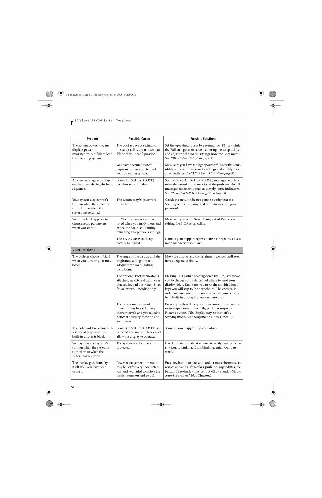
56
L i f e B o o k P 1 6 0 0 S e r i e s N o t e b o o k
The system powers up, and displays power-on information, but fails to load the operating system.
The boot sequence settings of the setup utility are not compat-ible with your configuration.
Set the operating source by pressing the [F2] key while the Fujitsu logo is on screen, entering the setup utility and adjusting the source settings from the Boot menu. See “BIOS Setup Utility” on page 32.
You have a secured system requiring a password to load your operating system.
Make sure you have the right password. Enter the setup utility and verify the Security settings and modify them as accordingly. See “BIOS Setup Utility” on page 32.
An error message is displayed on the screen during the boot sequence.
Power On Self Test (POST) has detected a problem.
See the Power On Self Test (POST) messages to deter-mine the meaning and severity of the problem. Not all messages are errors; some are simply status indicators. See “Power On Self Test Messages” on page 58.
Your system display won’t turn on when the system is turned on or when the system has resumed.
The system may be password-protected.
Check the status indicator panel to verify that the Security icon is blinking. If it is blinking, enter your password.
Your notebook appears to change setup parameters when you start it.
BIOS setup changes were not saved when you made them and exited the BIOS setup utility returning it to previous settings.
Make sure you select Save Changes And Exit when exiting the BIOS setup utility.
The BIOS CMOS back-up battery has failed.
Contact your support representative for repairs. This is not a user-serviceable part.
Video Problems
The built-in display is blank when you turn on your note-book.
The angle of the display and the brightness settings are not adequate for your lighting conditions.
Move the display and the brightness control until you have adequate visibility.
The optional Port Replicator is attached, an external monitor is plugged in, and the system is set for an external monitor only.
Pressing [F10] while holding down the [Fn] key allows you to change your selection of where to send your display video. Each time you press the combination of keys you will step to the next choice. The choices, in order are: built-in display only, external monitor only, both built-in display and external monitor.
The power management timeouts may be set for very short intervals and you failed to notice the display come on and go off again.
Press any button the keyboard, or move the mouse to restore operation. If that fails, push the Suspend/Resume button. (The display may be shut off by Standby mode, Auto Suspend or Video Timeout)
The notebook turned on with a series of beeps and your built-in display is blank.
Power On Self Test (POST) has detected a failure which does not allow the display to operate.
Contact your support representative.
Your system display won’t turn on when the system is turned on or when the system has resumed.
The system may be password-protected.
Check the status indicator panel to verify that the Secu-rity icon is blinking. If it is blinking, enter your pass-word.
The display goes blank by itself after you have been using it.
Power management timeouts may be set for very short inter-vals and you failed to notice the display come on and go off.
Press any button on the keyboard, or move the mouse to restore operation. If that fails, push the Suspend/Resume button. (The display may be shut off by Standby Mode, Auto Suspend or Video Timeout)
Problem Possible Cause Possible Solutions
P Series.book Page 56 Monday, October 9, 2006 10:58 AM

57
T r o u b l e s h o o t i n g
The display goes blank by itself after you have been using it.
(continued)
The notebook has gone into Video Timeout, Standby Mode, or Hibernate Mode because you have not used it for a period of time.
Press a button on the keyboard, or move the mouse to restore operation. If that fails, push the Suspend/Resume button. Check your power management settings, or close your applications and go to the Power Savings menu of the setup utility to adjust the timeout values to better suit your operation needs. See “BIOS Setup Utility” on page 32.
The display does not close. A foreign object, such as a paper clip, is stuck between the display and the keyboard.
Remove all foreign objects from the keyboard.
The display has bright or dark spots.
If the spots are very tiny and few in number, this is normal for a large LCD display.
This is normal; do nothing.
If the spots are numerous or large enough to interfere with your operation needs.
The display needs technical diagnosis; contact your support representative.
The application display uses only a portion of your screen and is surrounded by a dark frame.
You are running an application that does not support the lower pixel resolution and display compression is enabled.
When compensation is disabled, a clearer but smaller display for applications that use lower than the system resolution will result. You can fill the screen but have less resolution by changing your compensation setting. (See the Video Features submenu, located within the Advanced menu of the BIOS. See “BIOS Setup Utility” on page 32.
You have connected an external monitor and it does not display any information.
Your BIOS setup is not set to enable your external monitor.
Try toggling the video destination by pressing [Fn] and [F10] together, or check your BIOS setup and enable your external monitor. (See the Video Features submenu, located within the Advanced Menu of the BIOS. See “BIOS Setup Utility” on page 32.
Your external monitor is not properly installed.
Reinstall your device. See “External Video Port” on page 48.
Your operating system software is not set up with the correct software driver forthat device.
Check your device and operating system documentation and activate the proper driver.
You have connected an external monitor and it does not come on.
Your external monitor may not be compatible with your system.
See your monitor documentation and the External Monitor Support portions of the Specifications section. See “Specifications” on page 71.
Miscellaneous Problems
An error message is displayed on the screen during the operation of an application.
Application software often has its own set of error message displays.
See your application manual and help displays screens for more information. Not all messages are errors some may simply be status.
Can’t change screen orientation using Tablet and Pen Settings.
Incorrect system resolution. This LifeBook uses a lower resolution than that required by this feature. To rotate the screen, use the Rotation button.
Problem Possible Cause Possible Solutions
P Series.book Page 57 Monday, October 9, 2006 10:58 AM

58
L i f e B o o k P 1 6 0 0 S e r i e s N o t e b o o k
POWER ON SELF TEST MESSAGESThe following is an alphabetic list of error-and-status messages that Phoenix BIOS and/or your operating system can generate and an explanation of each message. Error messages are marked with an *. If an error message is displayed that is not in this list, write it down and check your operating system documentation both on screen and in the manual. If you can find no reference to the message and its meaning is not clear, contact your support representative for assistance.
nnnn Cache SRAM Passed Where nnnn is the amount of system cache in kilobytes successfully tested by the Power On Self Test. (This can only appear if you have an SRAM PC Card installed.)
*Extended RAM Failed at offset: nnnn Extended memory not working or not configured prop-erly. If you have an installed memory upgrade module, verify that the module is properly installed. If it is prop-erly installed, you may want to check your Windows Setup to be sure it is not using unavailable memory until you can contact your support representative.
nnnn Extended RAM Passed Where nnnn is the amount of memory in kilobytes successfully tested.
*Failing Bits: nnnn The hex number nnnnThis is a map of the bits at the memory address (in System, Extended, or Shadow memory) which failed the memory test. Each 1 (one) in the map indicates a failed bit. This is a serious fault that may cause you to lose data if you continue. Contact your support representative.
*Fixed Disk x Failure or Fixed Disk Controller Failure (where x = 1-4) The fixed disk is not working or not configured properly. This may mean that the hard drive type identified in your setup utility does not agree with the type detected by the Power On Self Test. Run the setup utility to check for the hard drive type settings and correct them if necessary. If the settings are OK and the message appears when you restart the system, there may be a serious fault which might cause you to lose data if you continue. Contact your support representative.
*Invalid NVRAM media typeProblem with NVRAM access. In the unlikely case that you see this message you may have some display prob-lems. You can continue operating but should contact your support representative for more information.
*Keyboard controller error The keyboard controller test failed. You may have to replace your keyboard or keyboard controller but may be able to use an external keyboard until then. Contact your support representative.
*Keyboard error Keyboard not working. You may have to replace your keyboard or keyboard controller but may be able touse an external keyboard until then. Contact your support representative.
*Keyboard error nn BIOS discovered a stuck key and displays the scan code for the stuck key. You may have to replace your keyboard but may be able to use an external keyboard until then. Contact your support representative.
*Operating system not found Operating system cannot be located on either drive A: or drive C: Enter the setup utility and see if both the fixed disk, and drive A: are properly identified and that the boot sequence is set correctly. Unless you have changed your installation greatly, the operating system should be on drive C:. If the setup utility is correctly set, your hard drive may be corrupted and your system may have to be re-installed from your back up media.
*Parity Check 1 nnnn Parity error found in the system bus. BIOS attempts to locate the address and display it on the screen. If it cannot locate the address, it displays “????”. This is apotentially data destroying failure. Contact yoursupport representative.
*Parity Check 2 nnnn Parity error found in the I/O bus. BIOS attempts to locate the address and display it on the screen. If it cannot locate the address, it displays “????”. This is apotentially data destroying failure. Contact yoursupport representative.
*Press <F1> to resume, <F2> to SETUP Displayed after any recoverable error message. Pressthe [F1] key to continue the boot process or the [F2]key to enter Setup and change any settings.
*Previous boot incomplete – Default configuration used Previous Power On Self Test did not complete success-fully. The Power On Self Test will load default values and offer to run Setup. If the previous failure was caused by incorrect values and they are not corrected, the next boot will likely fail also. If using the default settings does not allow you to complete a successful boot sequence, you should turn off the power and contact your support representative.
P Series.book Page 58 Monday, October 9, 2006 10:58 AM

59
T r o u b l e s h o o t i n g
*Real time clock error Real-time clock fails BIOS test. May require board repair. Contact your support representative.
*Shadow RAM Failed at offset: nnnn Shadow RAM failed at offset nnnn of the 64k block at which the error was detected. You are risking data corruption if you continue. Contact your support repre-sentative.
nnnn Shadow RAM Passed Where nnnn is the amount of shadow RAM in kilobytes successfully tested.
*System battery is dead – Replace and run SETUP The BIOS CMOS RAM memory hold up battery is dead. This is part of your BIOS and is a board mounted battery which requires a support representative to change. You can continue operating but you will have to use setup utility default values or reconfigure your setup utility every time you turn off your notebook.
System BIOS shadowed System BIOS copied to shadow RAM.
*System CMOS checksum bad – run SETUP BIOS CMOS RAM has been corrupted or modified incorrectly, perhaps by an application program that changes data stored in BIOS memory. Run Setup and reconfigure the system.
*System RAM Failed at offset: nnnn System memory failed at offset nnnn of in the 64k block at which the error was detected. This means that there is a fault in your built-in memory. If you continue to operate, you risk corrupting your data. Contact your support representative for repairs.
nnnn System RAM PassedWhere nnnn is the amount of system memory inkilobytes successfully tested.
*System timer error The timer test failed. The main clock that operates the computer is faulty. Requires repair of system board. Contact your support representative for repairs.
UMB upper limit segment address: nnnn Displays the address of the upper limit of Upper Memory Blocks, indicating released segments of the BIOS memory which may be reclaimed by a virtual memory manager.
Video BIOS shadowed Video BIOS successfully copied to shadow RAM.
MODEM RESULT CODESThe operating system and application software that is factory installed detects the modem characteristics and provides the necessary command strings to operate the modem. The internal modem operation is controlled by generic AT commands from the operating system and application software. The standard long form result codes may, in some cases, be displayed on your screen to keep you informed of the actions of your modem. The operating system and application software may suppress display of the result codes.
Examples of result codes are:
■ OK■ NO CARRIER■ NO DIALTONE■ CONNECT 53000 (Connection complete
at 53,000 bps.)■ ERROR■ FAX■ RING (This means an incoming call.)■ BUSY■ NO ANSWER
When using the internal modem with applications that are not factory installed refer to the application documentation.
P Series.book Page 59 Monday, October 9, 2006 10:58 AM

60
L i f e B o o k P S e r i e s N o t e b o o k - S e c t i o n F i v eL i f e B o o k P 1 6 0 0 S e r i e s N o t e b o o k
Restoring Your Pre-installed SoftwareThe Drivers and Applications Restore (DAR) CD contains sets of device drivers and Fujitsu utilities (in specific directories) that are unique to your notebook configuration for use as documented below.
Re-Installing Individual Drivers and Applications The Drivers and Applications CD can be used to selec-tively re-install drivers and/or applications that may have
been un-installed or corrupted.
To re-install drivers and/or applications:
1. Boot up the system and insert the DAR CD after Windows has started. A Fujitsu Installer screen is displayed after the CD is inserted.
2. After reading the License Agreement, click [I agree].
3. A window will appear containing a list of applica-tions, drivers, and utilities that you can install from the Drivers and Applications CD.
4. In the list, check off all the components you want to install. If you want to install all components, click [Select All]. Clicking [Select All] will select all of the blue-coded components; you must select grey and green components separately.
5. Once you have selected the components you wish to install, click [Install Selected Subsystems]; the components will be installed.
6. After the components are installed, click [OK], then click [Yes] when asked if you want to reboot the system.
RESTORING THE FACTORY IMAGEThe Restore Disc that came with your system contains two utilities:
■ The Recovery utility allows you to restore the original contents of the C: drive.
■ The Hard Disk Data Delete utility on this disc is used to delete all data on your hard disk and prevent it from being reused. Do not use the Hard Disk Data Delete utility unless you are absolutely certain that you want to erase your entire hard disk, including all partitions.
BOOT Priority ChangeBefore restoring an image, you must first verify that your system is set up to boot from the CD drive. To verify/change the boot-up priority (rather than booting-up from the hard drive or an external floppy disk drive), perform the following steps:
1. Start your system and press the [F2] key when the Fujitsu logo appears. You will enter the BIOS Setup Utility.
2. Using the arrow keys, go to the Boot menu.
3. Arrow down to the Boot Device Priority submenu. Press [Enter].
4. If “Optical Media Drive” or “CD-ROM Drive” is not at the top of the list, arrow down to the drive in the list, and press the space bar (or the + key) to move it to the top of the list. (The system attempts to boot from the devices in the order in which they are listed.). Note that the BIOS for some systems will indicate “CD-ROM Drive”, even when a DVD drive is connected.
5. If you have an external drive connected, proceed to step 6; otherwise, proceed to step 7.
6. If you have an external drive connected:
If you have access to the internet, visit the Fujitsu Support website at http://www.computers.us.fujitsu.com/support to check for the most current information, drivers and hints on how to perform recovery and system updates. See “Automatically Downloading Driver Updates” on page 61.
There may be certain free third-party applications pre-installed on your system that are not on the DAR CD. The latest versions of the applications can be downloaded from the third-party’s website.
The components listed are color-coded in terms of their install status. Blue indicates that the component can be installed. Green indicates that the component needs to be installed separately. Grey indicates a component that is already installed; grey items can be reinstalled, but prior to installation you will receive a reminder that the component is already installed.
• The use of this disc requires that you have a device capable of reading CDs attached to your system. If you do not have a built-in CD player, you will need to attach an external player. For more information on available external devices, visit our website at: www.shopfujitsu.com.
• This disc can only be used with the system with which it was purchased.
P Series.book Page 60 Monday, October 9, 2006 10:58 AM

61
T r o u b l e s h o o t i n g
• Select the Advanced menu in the BIOS window.
• Scroll down to the USB Features submenu and press the Enter key to open it.
• If Legacy USB Support is disabled, press the space bar to enable it.
• Scroll down to SCSI SubClass Support and press the space bar to enable it.
7. Press [F10], then click on [Yes] to exit the BIOS Setup Utility and return to the boot process.
After you have changed the boot priority, you can restore a backup image when you are booting up.
Procedure
1. Turn on the power to your system.
2. Ensure that you have a device that can read CDs either installed in your system or attached exter-nally to it.
3. Insert the Restore Disc into the drive tray.
4. Reboot your system.
5. After the system reboots, follow the instructions that appear to either restore your system image or erase all data from your hard disk.
AUTOMATICALLY DOWNLOADING DRIVER UPDATESYour system has a convenient tool called the Fujitsu Driver Update (FDU) utility. With FDU, you can choose to automatically or manually go to the Fujitsu site to check for new updates for your system.
The FDU icon should appear in the notification area at the bottom right of your screen (roll the cursor over the icons to find the correct one). If the FDU icon does not appear in the notification area, it can be started by going to [Start] -> All Programs, and clicking on Fujitsu Driver Update; this will create the icon automati-cally.
To invoke the FDU menu, right-click on the FDU icon. The menu contains the following items:
■ Check for updates nowAllows for manual driver update search. The first time it is used, you are prompted to agree to a user agreement. After clicking on the icon, the FDU auto-matically connects with the Fujitsu site to check for updates and downloads them. While downloading, the icon has a red bar through it, indicating that it cannot be used while the download is in process. When the update is complete, a message appears informing you of the fact.
■ Enable Automatic Update NotificationsAutomatically searches for new updates on a regular basis (approximately every 3 days).
■ Show update historyBrings up a screen that displays a history of updates that have been made via the FDU.
■ About Fujitsu Driver UpdateDisplays the FDU version number and copyright information
■ Fujitsu Driver Update ReadmeDisplays the FDU readme.
P Series.book Page 61 Monday, October 9, 2006 10:58 AM

62
L i f e B o o k P S e r i e s N o t e b o o k - S e c t i o n F i v eL i f e B o o k P 1 6 0 0 S e r i e s N o t e b o o k
P Series.book Page 62 Monday, October 9, 2006 10:58 AM

63
6Care and Maintenance
P Series.book Page 63 Monday, October 9, 2006 10:58 AM

64
L i f e B o o k P 1 6 0 0 S e r i e s N o t e b o o k
P Series.book Page 64 Monday, October 9, 2006 10:58 AM

65
C a r e a n d M a i n t e n a n c e
Care and MaintenanceIf you use your LifeBook P1600 Series notebook care-fully, you will increase its life and reliability. This section provides some tips for looking after the system and its
devices.
LIFEBOOK P1600 SERIES NOTEBOOKCaring for your LifeBook■ Your notebook is a durable but sensitive electronic
device. Treat it with care.
■ Make a habit of transporting it in a suitable carrying case.
■ To protect your notebook from damage and to opti-mize system performance, be sure to keep all air all vents unobstructed, clean, and clear of debris. This may require periodic cleaning, depending upon the environment in which the system is used.
■ Do not operate the system in areas where the air vents can be obstructed, such as in tight enclosures or on soft surfaces like a bed or cushion.
■ Do not attempt to service the computer yourself. Any unauthorized service performed on the computer will void the warranty.
■ Always follow installation instructions closely.
■ Keep it away from food and beverages.
■ If you accidentally spill liquid on your notebook:1. Turn it off.2. Position it so that the liquid can run out.3. Let it dry out for 24 hours, or longer if needed.4. If your system will not boot after it has dried out,
call your support representative.■ Do not use your notebook in a wet environment (near
a bathtub, swimming pool).
■ Always use the AC adapter and batteries that are approved for your system.
■ Avoid exposure to sand, dust and other environmental hazards.
■ Do not expose your notebook to direct sunlight for long periods of time as temperatures above 140° F (60° C) may damage your system.
■ Keep the covers closed on the connectors and slots when they are not in use.
■ Do not put heavy or sharp objects on the computer.
■ If you are carrying your notebook in a briefcase, or any other carrying case, make sure that there are no objects in the case pressing on the lid.
■ Do not drop your notebook.
■ Do not touch the screen with any sharp objects.
Cleaning your LifeBook■ Always disconnect the power plug. (Pull the plug, not
the cord.)
■ Clean your system with a damp, lint-free cloth. Do not use abrasives or solvents.
■ Use a soft cloth to remove dust from the screen. Never use glass cleaners.
Storing your LifeBook■ If storing your notebook for a month or longer, turn
the system off, fully charge the battery, then remove and store all Lithium ion batteries.
■ Store your notebook and batteries separately. If you store your system with a battery installed, the battery will discharge, and battery life will be reduced. In addition, a faulty battery might damage the system.
■ Store your notebook in a cool, dry location. Temperatures should remain between 13º F (-25º C) and 140º F (60º C).
Traveling with your LifeBook■ Do not transport your system while it is turned on.
■ Do not check your system as baggage. Carry it with you.
■ When traveling with the hard drive removed, wrap the drive in a non-conducting materials (cloth or paper). If you have the drive checked by hand, be ready to install the drive if needed. Never put your hard drive through a metal detector. Have your hard drive hand-inspected by security personnel. You can however, put your hard drive through a properly tuned X-ray machine.
■ Take the necessary plug adapters if you're traveling overseas. Check the following diagram to determine which adapter you'll need or ask your travel agent.
Electrical equipment may be hazardous if misused. Operations of this product or similar products, must always be supervised by an adult. Do not allow children access to the interior of any electrical products and do not permit them to handle any cables.
Do not use excessive force when tapping or writing on the screen with the stylus or your finger. Use of excessive force could result in damage to the LCD and/or Touch Screen.
P Series.book Page 65 Monday, October 9, 2006 10:58 AM

66
L i f e B o o k P 1 6 0 0 S e r i e s N o t e b o o k
Figure 6-1. Outlet types
KEYBOARDCaring for your KeyboardThe keyboard of your computer is a very sensitive instrument. It is made up of many switches that are activated when you press on the keys. The keyboard is a major component of the heat dissipation system in a notebook. Due to heat and size considerations the keyboard is not sealed. Because the keys are so close together, it is not easy for the user to see when liquids have fallen onto the circuitry below the keys.
Attempting to clean the keyboard with a spray on cleaner or rag soaked with cleaner the liquid can drip onto the circuitry sight unseen. Once the liquid seeps between the layers of circuitry, it can cause corrosion or other damage to the circuits. This can result in keys which no longer operate, or which, when pressed, record the wrong characters and other similar failures.
There is no repair for this problem other than replace-ment. The solution is to become aware of the issue and take appropriate steps to protect your keyboard.
To clean the keyboard, use a rag dampened slightly with cleaning solution. Use extreme care to prevent liquid from dripping between the keys. Spraying directly on the keys should be avoided. The spray should be applied first to the cloth, and then the cloth wiped over the keys.
BATTERIESCaring for your Batteries■ Always handle batteries carefully.
■ Do not short-circuit the battery terminals (that is, do not touch both terminals with a metal object). Do not carry lose batteries in a pocket or purse where they
may mix with coins, keys, or other metal objects. Doing so may cause an explosion or fire.
■ Do not drop, puncture, disassemble, mutilate or incin-erate the battery.
■ Recharge batteries only as described in this manual and only in ventilated areas.
■ Do not leave batteries in hot locations for more than a day or two. Intense heat can shorten battery life.
■ Do not leave a battery in storage for longer than six months without recharging it.
Increasing Battery Life■ Keep brightness to the lowest comfortable level.
■ Set the power management for maximum battery life.
■ Put your notebook in Standby mode when it is turned on and you are not actually using it.
■ Disable the Windows CD auto insert function.
■ Always use fully charged batteries.
OPTIONAL FLOPPY DISK DRIVE AND FLOPPY DISKSCaring for your Floppy Disks■ Avoid using floppy disks in damp and dusty locations.
■ Never store a floppy disk near a magnet or magnetic field.
■ Do not use a pencil or an eraser on a disk or disk label.
■ Avoid storing the floppy disks in extremely hot or cold locations, or in locations subject to severe temperature changes. Store at temperatures between 50º F (10º C) and 125º F (52º C).
■ Do not touch the exposed part of the disk behind the metal shutter.
Caring for your Optional Floppy Disk Drive■ To clean, wipe the floppy disk drive clean with a dry
soft cloth, or with a soft cloth dampened with water or a solution of neutral detergent. Never use benzene, paint thinner or other volatile material.
■ Avoid storing the floppy disk drive in extremely hot or cold locations, or in locations subject to severe temperature changes. Store at temperatures between 50º F (10º C) and 125º F (52º C).
■ Keep the floppy disk drive out of direct sunlight and away from heating equipment.
■ Avoid storing the floppy disk drive in locations subject to shock and vibration.
■ Never use the floppy disk drive with any liquid, metal, or other foreign matter inside the drive or disk.
■ Never disassemble or dismantle your floppy disk drive.
Outlet Type Location
United States, Canada, Mexico, parts of Latin America, Japan, Korea, the
Philippines, Taiwan
Russia and the Commonwealth of Independent States (CIS), most of Europe, parts of Latin America, the Middle East, parts of Africa, Hong Kong, India, most of South Asia
United Kingdom, Ireland, Malaysia, Singapore, parts of Africa
China, Australia, New Zealand
P Series.book Page 66 Monday, October 9, 2006 10:58 AM

67
C a r e a n d M a i n t e n a n c e
OPTIONAL OPTICAL DRIVE AND DISCSCaring for your discsCDs and DVD discs are precision devices and will func-tion reliably if given reasonable care.
■ Always store your discs in their case when not in use.
■ Always handle discs by the edges and avoid touching the surface.
■ Avoid storing any discs in extreme temperatures.
■ Do not bend discs or set heavy objects on them.
■ Do not spill liquids on discs.
■ Do not scratch discs.
■ Do not put a label on discs.
■ Do not get dust on discs.
■ Never write on the label surface with a ballpoint pen or pencil. Always use a felt pen.
■ If a disc is subjected to a sudden change in tempera-ture, cold to warm condensation may form on the sur-face. Wipe the moisture off with a clean, soft, lint free cloth and let it dry at room temperature. DO NOT use a hair dryer or heater to dry discs.
■ If a disc is dirty, use only a disc cleaner or wipe it with a clean, soft, lint free cloth starting from the inner edge and wiping to the outer edge.
Caring for your Optional Optical DriveYour optical drive is durable but you must treat it with care. Please pay attention to the following points:
■ The drive rotates the compact disk at a very high speed. Do not carry it around or subject it to shock or vibration with the power on.
■ Avoid using or storing the drive where it will be exposed to extreme temperatures.
■ Avoid using or storing the drive where it is damp or dusty.
■ Use of a commercially-available lens cleaner kit is recommended to maintain the drive lens.
■ Avoid using or storing the drive near magnets or devices that generate strong magnetic fields.
■ Avoid using or storing the drive where it will be subjected to shock or vibration.
■ Do not disassemble or dismantle the optical drive.
PC CARDSCaring for your PC Cards PC Cards are durable, but you must treat them with care. The documentation supplied with your PC Cards provides specific information for caring for the cards.
When you don’t have a PC Card installed in your system, you should be sure to install the PC Card slot inserts that came with your system. These will help to keep dust and dirt out of your system.
P Series.book Page 67 Monday, October 9, 2006 10:58 AM

68
L i f e B o o k P 1 6 0 0 S e r i e s N o t e b o o k
P Series.book Page 68 Monday, October 9, 2006 10:58 AM
69
7SystemSpecifications
P Series.book Page 69 Monday, October 9, 2006 10:58 AM

70
L i f e B o o k P 1 6 0 0 S e r i e s N o t e b o o k
P Series.book Page 70 Monday, October 9, 2006 10:58 AM

71
S p e c i f i c a t i o n s
SpecificationsThis section provides the hardware and environmental specifications for your LifeBook P1600 Series notebook. Specifications of particular configurations will vary.
CONFIGURATION LABELYour LifeBook P1600 Series notebook has a configura-tion label located on the bottom. (See figure 2-8 on page 13 for location). This label contains specific infor-mation regarding the options you’ve chosen for your notebook. Following is an example label and informa-tion on how to read your own configuration label.
Figure 7-1. Configuration Label
LifeBook P1600 Series notebook Specifications
The specifications for your particular model may vary. To determine the specifications for your system, please visit our website at: us.fujitsu.com/computers.
Physical Specifications
Dimensions 9.13” w x 6.57” d x 1.36" / 1.46" (232 mm x 167 mm x 34.5/37 mm)
Processing Specifications
CPU/Speed Intel® Core™ Solo Processor ULV U1400 (1.2 GHz)
Front Side Bus (FSB)
533 MHz
Chip set 945GMS
Memory/Storage Specifications
Main RAM • 512 MB and 1.0 GB SDRAM modules available, with a system maximum of 1.0 GB (DDR2 533 MHz)
• 172-pin Micro DIMM slot
L2 cache 2 MB on-die
BIOS ROM8 Mb (for System BIOS) plus 8 Mb (for fingerprint recognition)
P1600, U1400, 8.9 WXGA, 512M, 60G, MODEM/LAN/WLAN, WIN XPP
Configuration P/N: AP8XXXXXXXXXXXXXFPC P/N: FPCMXXXXXX
Model
Processor
ScreenSize
OperatingSystem
Hard Drive
Part Number Configuration ID
Memory Communications
Hard disk drive
• 1.8” HDD
• 30 GB, 60 GB or 80 GB IDE (4200 rpm) DMA 100
• Shock-mounted
• Shock Sensor feature
• SMART Support
Display Specifications
Display 8.9" TFT WXGA (1280 x 768), 16M colors:
• Color LCD
• Resistive Digitizer
• 32-bit color
• External monitor support: SXGA (1280 x 1024 maximum)
• Dot pitch: 0.240 x 0.240 mm
VRAM Up to 128 MB of shared memory using Unified Memory Architecture (UMA). Dynamically responds to application requirements and allocates the proper amount of memory for optimal graphics and performance.
Interface Specifications
Integrated Interfaces
• Modem (RJ-11)
• LAN (RJ-45)
• USB 2.0 x 2
• DC-In
• Analog RGB, Mini D-SUB 15-pin connector for external VGA monitor
• Docking connector
Interfaceson Optional Port Replicator
• DC Power
• LAN (RJ-45)
• 15-pin D-SUB connector for external VGA monitor
• USB 2.0 x 2
• Docking Port
PC Card Slot Dedicated slot for PCMCIA Card, Type I or II
SD Slot Dedicated slot for SD Card
User Interface support
• Keyboard Pitch: 19 mm, Stroke: 2 mm
• Quick Point pointing device with scroll button
• Passive digitizer with pen input
• On-screen keyboard
LifeBook P1600 Series notebook Specifications
P Series.book Page 71 Monday, October 9, 2006 10:58 AM

72
L i f e B o o k P 1 6 0 0 S e r i e s N o t e b o o k
Audio • Sigmatel ST9228
• Internal digital microphone
• Mono speaker
• Mono microphone and stereo headphone jacks
• 26 adjustable audio levels
User Controls
• Programmable Security/Application Buttons, each with primary and secondary functions (default applications: Calculator and WordPad) as well as security functions
• Trusted Platform Module (TPM) support
• Suspend/Resume button
Status Indicators (LEDs)
• Power
• Battery charging
• Battery level
• Hard disk drive
• Caps Lock
• Num Lock
• Scroll Lock
Power Specifications
Main Battery • 3-cell
• Removable, Lithium ion
• 10.8 V @2600 mAh, max. 28 WHr
• Recharge Time: Approximately 2.5 hours
Optional Battery
• 6-cell
• Removable, Lithium ion
• 10.8V @ 5200 mAh, max. 56.0 WHr
• Recharge Time: Approximately 4.5 hours
AC Adapter Autosensing 100 - 240V, supplying 16 VDC, with a minimum current of 2.5 A
Environmental Specifications
Temperature Operating: 41o to 95o F (5o to 35o C) Non-operating: 5o to 140o F
(-15o to 60o C)
LifeBook P1600 Series notebook Specifications
Humidity Operating: 20 to 85% non-condensingNon-operating: 8 to 85% non-condensing
Agency Approval Specifications
Emissions
• EN55022 (CISPR22) Class B
• FCC 15, Class B
• FCC 15C, 15.247
• ICES-003
• Canada RSS-210
• ETSI EN 300 328-1 V1.3.1: 2001
• ETSI EN 300 328-2 V1.2.1: 2001_12
• ETSI EN 301 498-17 V1.2.1: 2002
• ETSI EN 301 498-1 V1.4.1: 2002
Immunity • EN55024 (1998), +A1
Safety • UL and cUL Listed, UL 60950-1
Telecom• FCC Part 68
• IC CS-03
Additional Specifications
Operating Systems
• Microsoft® Windows® XP Pro
• Microsoft Windows XP Tablet PC Edition
LifeBook P1600 Series notebook Specifications
P Series.book Page 72 Monday, October 9, 2006 10:58 AM

73
R e g u l a t o r y I n f o r m a t i o n
Regulatory Information
FCC NOTICESNotice to Users of Radios and TelevisionThese limits are designed to provide reasonable protec-tion against harmful interference in a residential installa-tion. This equipment generates, uses, and can radiate radio frequency energy and, if not installed and used in accordance with the instructions, may cause harmful interference to radio communications. However, there is no guarantee that interference will not occur in a partic-ular installation. If this equipment does cause harmful interference to radio or television reception, which can be determined by turning the equipment off and on, the user is encouraged to try to correct the interference by one or more of the following measures:
■ Reorient or relocate the receiving antenna.■ Increase the separation between the equipment and
receiver.■ Connect the equipment into an outlet that is on a
different circuit than the receiver.■ Consult the dealer or an experienced radio/TV
technician for help.
Shielded interconnect cables must be employed with this equipment to ensure compliance with the pertinent RF emission limits governing this device.
Notice to Users of the US Telephone NetworkThis equipment contains an internal modem that complies with Part 68 of the FCC rules. On the bottom of this equipment is a label that contains, among other information, the FCC registration number and ringer equivalence number (REN) for this equipment. If requested, this information must be provided to the tele-phone company.
This equipment is designed to be connected to the tele-phone network or premises wiring using a standard jack type USOC RJ11C. A plug and jack used to connect this equipment to the premises wiring and telephone network must comply with the applicable FCC Part 68 rules and requirements adopted by the ACTA. A compliant telephone cord and modular plug is provided with this product. It is designed to be connected to a compatible modular jack that is also compliant.
The ringer equivalent number (REN) of this equipment is 0.1B as shown on the label. The REN is used to deter-mine the number of devices that may be connected to a telephone line. Excessive RENs on a telephone may result in the devices not ringing in response to an
incoming call. In most but not all areas, the sum of RENs should not exceed five (5.0). To be certain of the number of devices that may be connected to a line, as determined by the total RENs, contact the local tele-phone company.
If this equipment causes harm to the telephone network, the telephone company will notify you in advance that temporary discontinuance of service may be required. But if advance notice isn’t practical, the telephone company will notify the customer as soon as possible. Also, you will be advised of your right to file a complaint with the FCC if you believe it is necessary.
The telephone company may make changes in its facili-ties, equipment, operations or procedures that could effect the operation of the equipment. If this happens the telephone company will provide advance notice in order for you to make necessary modifications to main-tain uninterrupted service.
If trouble is experienced with this equipment, for repair or warranty information, please refer to the manual or contact Fujitsu Computer Systems Corporation, Customer Service. If the equipment is causing harm to the telephone network, the telephone company may request that you disconnect the equipment until the problem is resolved.
The equipment cannot be used on public coin service provided by the telephone company. Connection to party line service is subject to state tariffs. (Contact the state public utility commission, public service commis-sion or corporation commission for information).
If your home has specially wired alarm equipment connected to the telephone line, ensure the installation of this computer does not disable your alarm equip-ment. If you have any questions about what will disable alarm equipment, consult your telephone company or a qualified installer.
The Telephone Consumer Protection Act of 1991 makes it unlawful for any person to use a computer or other electronic device to send any message via a telephone fax machine unless such message clearly contains in a margin at the top or bottom of each transmitted page or on the first page of the transmission, the date an time it is sent and an identification of the business or other entity, or other individual sending the message and the telephone number of the sending machine or such busi-ness, other entity, or individual.
Changes or modifications not expressly approved by Fujitsu could void this user’s authority to operate the equipment
P Series.book Page 73 Monday, October 9, 2006 10:58 AM

74
L i f e B o o k P S e r i e s N o t e b o o k - S e c t i o n S e v e nL i f e B o o k P 1 6 0 0 S e r i e s N o t e b o o k
DOC (INDUSTRY CANADA) NOTICESNotice to Users of Radios and TelevisionThis Class B digital apparatus meets all requirements of Canadian Interference-Causing Equipment Regulations.
CET appareil numérique de la class B respecte toutes les exigence du Réglement sur le matérial brouilleur du Canada.
Notice to Users of the Canadian Telephone Network NOTICE: This equipment meets the applicable Industry Canada Terminal Equipment Technical Specifications. This is confirmed by the registration number. The abbreviation, IC, before the registration number signi-fies that registration was performed based on a Declara-tion of Conformity indicating that Industry Canada technical specifications were met. It does not imply that Industry Canada approved the equipment.
Before connecting this equipment to a telephone line the user should ensure that it is permissible to connect this equipment to the local telecommunication facilities. The user should be aware that compliance with the certifica-tion standards does not prevent service degradation in some situations.
Repairs to telecommunication equipment should be made by a Canadian authorized maintenance facility. Any repairs or alterations not expressly approved by Fujitsu or any equipment failures may give the telecom-munication company cause to request the user to disconnect the equipment from the telephone line.
NOTICE: The Ringer Equivalence Number (REN) for this terminal equipment is 0.1B. The REN assigned to each terminal equipment provides an indication of the maximum number of terminals allowed to be connected to a telephone interface. The termination on an interface may consist of any combination of devices subject only to the requirement that the sum of the Ringer Equiva-lence Numbers of all the devices does not exceed five.
Avis Aux Utilisateurs Du Réseau Téléphonique CanadienAVIS: Le présent matériel est conforme aux spécifica-tions techniques d’Industrie Canada applicables au matériel terminal. Cette conformité est confirmée par le numéro d’enregistrement. Le sigle IC, placé devant le numéro d’enregistrement signifie que l’enregistrement s’est effectué conformément à une déclaration de conformité et indique que les spécifications techniques d’Industrie Canada ont été respectées. Il n’implique pas qu’Industrie Canada a approuvé le matériel.
Avant de connecter cet équipement à une ligne télépho-nique, l’utilisateur doit vérifier s’il est permis de connecter cet équipement aux installations de télécom-munications locales. L’utilisateur est averti que même la conformité aux normes de certification ne peut dans certains cas empêcher la dégradation du service.
Les réparations de l’équipement de télécommunications doivent être effectuées par un service de maintenance agréé au Canada. Toute réparation ou modification, qui n’est pas expressément approuvée par Fujitsu, ou toute défaillance de l’équipement peut entraîner la compagnie de télécommunications à exiger que l’utilisateur décon-necte l’équipement de la ligne téléphonique.
AVIS: L’indice d’équivalence de la sonnerie (IES) du présent matériel est de 0.1B. L’IES assigné à chaque dispositif terminal indique le nombre maximal de terminaux qui peuvent être raccordés à une interface téléphonique. La terminaison d’une interface peut consister en une combinaison quelconque de dispositifs, à la seule condition que la somme d’indices d’équiva-
lence de la sonnerie de tous les dispositifs n’excède pas 5.
For safety, users should ensure that the electrical ground of the power utility, the telephone lines and the metallic water pipes are connected together. Users should NOT attempt to make such connections themselves but should contact the appro-priate electric inspection authority or elec-trician. This may be particularly important in rural areas.
Pour assurer la sécurité, les utilisateurs doivent vérifier que la prise de terre du ser-vice d’électricité, les lignes télphoniques et les conduites d’eau métalliques sont con-nectées ensemble. Les utilisateurs NE doivent PAS tenter d’établir ces connex-ions eux-mêmes, mais doivent contacter les services d’inspection d’installations électriques appropriés ou un électricien. Ceci peut être particulièrement important en régions rurales.
P Series.book Page 74 Monday, October 9, 2006 10:58 AM

75
8Glossary
P Series.book Page 75 Monday, October 9, 2006 10:58 AM

76
L i f e B o o k P 1 6 0 0 S e r i e s N o t e b o o k
P Series.book Page 76 Monday, October 9, 2006 10:58 AM

77
G l o s s a r y
GlossaryAC AdapterA device which converts the AC voltage from a wall outlet to the DC voltage needed to power your note-book.
ACPIAdvanced Configuration and Power Interface
Active-Matrix DisplayA type of technology for making flat-panel displays which has a transistor or similar device for every pixel on the screen.
AdHoc
A designation for wireless LAN network configuration. It indicates a form of communication limited to those personal computers which have wireless LAN function. For details, refer to “Ad hoc mode” on page 86.
ADSL
Asymmetric Digital Subscriber Line
Technology for transporting high bit-rate services over ordinary phone lines.
Auto/Airline AdapterA device which converts the DC voltage from an auto-mobile cigarette lighter or aircraft DC power outlet to the DC voltage needed to power your notebook.
BIOSBasic Input-Output System. A program and set of default parameters stored in ROM which tests and operates your notebook when you turn it on until it loads your installed operating system from disk. Infor-mation from the BIOS is transferred to the installed operating system to provide it with information on the configuration and status of the hardware.
BitAn abbreviation for binary digit. A single piece of information which is either a one (1) or a zero (0).
bpsAn abbreviation for bits per second. Used to describe data transfer rates.
BootTo start-up a computer and load its operating system from disk, ROM or other storage media into RAM.
BusAn electrical circuit which passes data between the CPU and the sub-assemblies inside your notebook.
Byte8 bits of parallel binary information.
Cache MemoryA block of memory built into the micro-processor which is much faster to access than your system RAM and used in specially structured ways to make your overall data handling time faster.
CardBusA faster, 32-bit version of the PC Card interface which offers performance similar to the 32-bit PCI architecture.
CD-ROMCompact disk read only memory. This is a form of digital data storage which is read optically with a laser rather than a magnetic head. A typical CD-ROM can contain about 600MB of data and is not subject to heads crashing into the surface and destroying the data when there is a failure nor to wear from reading.
Channel
The frequency band of wireless LAN to be used in communications over wireless LAN or at the access point.
CMOS RAMComplementary metal oxide semiconductor random access memory. This is a technology for manufacturing random access memory which requires very low levels of power to operate.
CommandAn instruction which you give your operating system. Example: run a particular application or format a floppy disk.
ConfigurationThe combination of hardware and software that makes up your system and how it is allocated for use.
CRTCathode Ray Tube. A display device which uses a beam of electronic particles striking a luminescent screen. It produces a visual image by varying the position and intensity of the beam.
DataThe information a system stores and processes.
DCDirect current. A voltage or current that does not fluctuate periodically with time.
Default ValueA pre programmed value to be used if you fail to set your own.
P Series.book Page 77 Monday, October 9, 2006 10:58 AM

78
L i f e B o o k P 1 6 0 0 S e r i e s N o t e b o o k
DHCP
Dynamic Host Configuration Protocol
A protocol used for automatically fetching communica-tion parameters such as IP addresses. The side which assigns IP address is called DHCP server and the side that is assigned it is called DHCP client.
DIMMDual-in-line memory module.
DiskA spinning platter of magnetic data storage media. If the platter is very stiff it is a hard drive, if it is highly flexible it is a floppy disk, if it is a floppy disk in a hard housing with a shutter it is commonly called a diskette.
Disk DriveThe hardware which spins the disk and has the heads and control circuitry for reading and writing the data on the disk.
DisketteA floppy disk in a hard housing with a shutter.
DMADirect Memory Access
Special circuitry for memory to memory transfers of data which do not require CPU action.
DMIDesktop Management Interface
A standard that provides PC management applications with a common method of locally or remotely querying and configuring PC computer systems, hardware and software components, and peripherals.
DNS
Domain Name System
A function that controls the correspondence of IP addresses assigned to a computer with the name. Even for those computers whose IP addresses are unknown, if their names are known, it is possible to communicate with them.
DOSDisk Operating System (MS-DOS is a Microsoft Disk Operating System).
DriverA computer program which converts application and operating system commands to external devices into the exact form required by a specific brand and model of device in order to produce the desired results from that particular equipment.
ECPExtended Capability Port. A set of standards for high speed data communication and interconnection between electronic devices.
Encryption Key (Network Key)
Key information used to encode data for data transfer.
This device uses the same encryption key to encode and decode the data, and the identical encryption key is required between the sender and receiver.
ESDElectro-Static Discharge. The sudden discharge of elec-tricity from a static charge which has built-up slowly. Example: the shock you get from a doorknob on a dry day or the sparks you get from brushing hair on a dry day.
Extended MemoryAll memory more than the 640KB recognized by MS-DOS as system memory.
FCCFederal Communication Commission.
Floppy DiskA spinning platter of magnetic data storage media which is highly flexible.
GBGigabyte.
Hard driveA spinning platter of magnetic data storage media where the platter is very stiff.
I/OInput/Output. Data entering and leaving your notebook in electronic form.
I/O PortThe connector and associated control circuits for data entering and leaving your notebook in electronic form.
IDEIntelligent Drive Electronics. A type of control interface for a hard drive which is inside the hard drive unit.
IEEE 1394Industry standard that allows you to connect between your notebook and a peripheral device such as a digital camera. Also known as “Firewire” or “iLINK”.
IEEE802.11aOne of the wireless LAN standards prescribed by the 802 committee in charge of establishing standards of LAN technology in IEEE (Institute of Electrical and Electronic Engineers). This standard allows communications at the
P Series.book Page 78 Monday, October 9, 2006 10:58 AM

79
G l o s s a r y
maximum speed of 54 Mbps by using a 5 GHz band which can freely be used without radio communication license.
IEEE802.11bOne of the wireless LAN standards prescribed by 802 committee in charge of establishing standards of LAN technology in IEEE (Institute of Electrical and Elec-tronic Engineers). It allows communications at the maximum speed of 11 Mbps by a band of 2.4 GHz (ISM band) which can freely be used without radio communi-cation license.
IEEE802.11gOne of the wireless LAN standards prescribed by 802 committee in charge of establishing standards of LAN technology in IEEE (Institute of Electrical and Elec-tronic Engineers). It allows communications at the maximum speed of 54 Mbps by a band of 2.4 GHz (ISM band) which can freely be used without radio communi-cation license.
InfraredLight just beyond the red portion of the visible light spectrum which is invisible to humans.
Infrastructure
A designation of Wireless LAN network configurations. It indicates a form of communication using an Access Point.
IP Address
An address used for computers to communicate in the TCP/IP environment.
Current IPv4 (version 4) uses four values in the range between 1 and 255. (Example: 192.168.100.123).
There are two types of IP address: global address and private address.
The global address is an only address in the world. It is controlled by JPNIC (Japan Network Information Center). A private address is an only address in the closed network.
IRAn abbreviation for infrared.
IrDAInfrared Data Association. An organization which produces standards for communication using infrared as the carrier.
IRQInterrupt Request
An acronym for the hardware signal to the CPU that an external event has occurred which needs to be processed.
KB Kilobyte.
LANLocal Area Network
An interconnection of computers and peripherals within a single limited geographic location which can pass programs and data amongst themselves.
LCDLiquid Crystal Display
A type of display which makes images by controlling the orientation of crystals in a crystalline liquid.
Lithium ion BatteryA type of rechargeable battery which has a high power-time life for its size and is not subject to the memory effect as Nickel Cadmium batteries.
LPT PortLine Printer Port. A way of referring to parallel interface ports because historically line printers were the first and latter the most common device connected to parallel ports.
MAC Address
Media Access Control Address
A unique physical address of a network card. For Ethernet, the first three bytes are used as the vendor code, controlled and assigned by IEEE. The remaining three bytes are controlled by each vendor (preventing overlap), therefore, every Ethernet card is given a unique physical address in the world, being assigned with a different address from other cards. For Ethernet, frames are sent and received based on this address.
MBMegabyte.
Megahertz1,000,000 cycles per second.
MemoryA repository for data and applications which is readily accessible to your notebook’s CPU.
MHzMegahertz.
MIDIMusical Instrument Digital Interface. A standard communication protocol for exchange of information between computers and sound producers such as synthesizers.
P Series.book Page 79 Monday, October 9, 2006 10:58 AM

80
L i f e B o o k P 1 6 0 0 S e r i e s N o t e b o o k
ModemA contraction for MOdulator-DEModulator. The equipment which connects a computer or other data terminal to a communication line.
MonauralA system using one channel to process sound from all sources.
MPU-401A standard for MIDI interfaces and connectors.
MTU
Maximum Transmission Unit
The maximum data size that can be transferred at a time through the Internet or other networks. You can set a smaller MTU size to obtain successful communication, if you have difficulty transferring data due to the fact that the maximum size is too large.
Network authenticationThe method of authentication performed by wireless LAN clients to connect with the access point. There are two types: open system authentication and shared key authentication. The type of authentication must be set to each client and also coincide with the setting of access point with which to communicate. Network authentica-tion is sometimes called authentication mode.
Network keyData that is used for encrypting data in data communi-cation. The personal computer uses the same network key both for data encryption and decryption, therefore, it is necessary to set the same network key as the other side of communication.
Network name (SSID: Security Set Identifier)When a wireless LAN network is configured, grouping is performed to avoid interference or data theft. This grouping is performed with “Network name (SSID)”. In order to improve security, the network key is set allowing no communication unless “Network name (SSID)” coincides with the network key.
NTSCNational TV Standards Commission. The standard for TV broadcast and reception for the USA.
Open system authenticationOne of network authentication types for wireless LAN. Since there is no check of network key upon authentica-tion, clients can connect to the access point without submitting correct network keys. However, in case of actual communications, the same network key must be set. Open system authentication is sometimes called Open key authentication.
Operating SystemA group of control programs that convert application commands, including driver programs, into the exact form required by a specific brand and model of micro-processor in order to produce the desired results from that particular equipment.
PartitionA block of space on a hard drive which is set aside and made to appear to the operating system as if it were a separate disk, and addressed by the operating system accordingly.
PCMCIAPCMCIA is a trademark of the Personal Computer Memory Card International Association. The Personal Computer Memory Card International Association is an organization that sets standards for add-in cards for personal computers.
Peripheral DeviceA piece of equipment which performs a specific function associated with but not integral to a computer. Examples: a printer, a modem, a CD-ROM.
Pitch (keyboard)The distance between the centers of the letter keys of a keyboard.
PixelThe smallest element of a display, a dot of color on your display screen. The more pixels per area the clearer your image will appear.
POSTPower On Self Test. A program which is part of the BIOS which checks the configuration and operating condition of your hardware whenever power is applied to your notebook. Status and error messages may be displayed before the operating system is loaded. If the self test detects failures that are so serious that operation can not continue, the operating system will not be loaded.
PPPoEPoint to Point Protocol over Ethernet.
A protocol for Ethernet, using a Point-to-Point Protocol (PPP), which is used for connection on the phone line.
ProgramAn integrated set of coded commands to your computers telling your hardware what to do and how and when to do it.
Protocol
Procedures and rules use to send and receive data between computers.
- Method of sending and receiving data
- Process used to handle communication errors
P Series.book Page 80 Monday, October 9, 2006 10:58 AM

81
G l o s s a r y
Conditions required for communication are organized in procedures for correct transfer of information.
RAMRandom Access Memory. A hardware component of your notebook that holds binary information (both program and data) as long as it has the proper power applied to it.
RAM ModuleA printed circuit card with memory and associated circuitry which allows the user to add additional memory to the computer without special tools.
ResetThe act of reloading the operating system. A reset erases all information stored in RAM.
RestartSee Reset.
ResumeTo proceed after interruption. In your notebook this refers to returning to active operation after having been in one of the suspension states.
ROMRead Only Memory. A form of memory in which infor-mation is stored by physically altering the material. Data stored in this way can not be changed by your notebook and does not require power to maintain it.
SDRAMSynchronous Dynamic Random Access Memory.
Serial PortA connection to another device through which data is transferred one bit at a time on a single wire with any other wires only for control of the device not for transfer of data.
Shared key authenticationOne of the network authentication types for wireless LAN. Upon authentication, the access point checks whether the same network key is set to the client. If the client uses a wrong network key or the network key itself is not set, authentication is unsuccessful, allowing no communications with the access point.
SMARTSelf-Monitoring, Analysis and Reporting Technology (SMART) is an emerging technology that provides near-term failure predictions for hard drives. When SMART is enabled the hard drive monitors pre-determined drive attributes that are susceptible to degradation over time. If a failure is likely to occur, SMART makes a status report available so that the notebook can prompt the user to back up the data on the drive. Naturally not all failures are predictable. SMART predictability is limited to those attributes which the drive can self-monitor. In
those cases where SMART can give advance warning, a considerable amount of precious data can be saved.
SRAMStatic random access memory. A specific technology of making RAM which does not require periodic data refreshing.
SSID
Service Set Identifier
Specifies which network you are joining. Some systems allow you to specify any SSID as an option so you can join any network.
StandbyTo make inoperative for a period of time. Your notebook uses various suspension states to reduce power consumption and prolong the charge of your battery.
Status IndicatorA display which reports the condition of some portion of your hardware. On your notebook this is an LCD screen just above the keyboard.
Stereo (audio)A system using two channels to process sound from two different sources.
Subnet maskTCP-IP network is controlled by being divided into multiple smaller networks (subnets). IP address consists of the subnet address and the address of each computer. Subnet mask defines how many bits of IP address comprise the subnet address. The same value shall be set among computers communicating with each other.
SVGASuper VGA.
S-VideoSuper Video. A component video system for driving a TV or computer monitor.
System ClockAn oscillator of fixed precise frequency which synchro-nizes the operation of the system and is counted to provide time of day and date.
TCP/IP
Transmission Control Protocol/Internet Protocol.A standard Internet protocol that is most widely used.
TFTThin Film Transistor – A technology for flat display panels which uses a thin film matrix of transistors to control each pixel of the display screen individually.
P Series.book Page 81 Monday, October 9, 2006 10:58 AM

82
L i f e B o o k P 1 6 0 0 S e r i e s N o t e b o o k
ULUnderwriters Laboratories – An independent organiza-tion that tests and certifies the electrical safety of devices.
USBUniversal Serial Bus.Standard that allows you to simultaneously connect up to 127 USB devices such as game pads, pointing devices, printers, and keyboards to your computer.
VGAVideo Graphics Array. A video display standard originally introduced by IBM with the PS/2 series of personal computers.
VRAMVideo Random Access Memory. A memory dedicated to video display data and control.
Wi-Fi Compatible
Wi-Fi (Wireless Fidelity) Identifies that the product has passed the interoperability test, supplied by the WECA (Wireless Ethernet Compatibility Alliance), which guar-antees the interoperability of wireless IEEE 802.11 LAN products. For more information on the Wi-Fi standard, go to the WECA website at: www.wirelessethernet.com.
WLANWireless Local Area Network. A wireless interconnection of computers and peripherals within a single limited geographic location which can pass programs and data amongst themselves.
Write ProtectPrevent alteration of the binary state of all bits in a storage media. Example: all information on a device such as a floppy diskette; a block of space in a storage media such as a partition of a hard drive; a file or direc-tory of floppy diskette or hard drive.
XGAExtended VGA.
P Series.book Page 82 Monday, October 9, 2006 10:58 AM

83
Appendix AIntegrated WirelessLAN* User’s Guide
*Optional Device
P Series.book Page 83 Monday, October 9, 2006 10:58 AM

84
L i f e B o o k P 1 6 0 0 S e r i e s N o t e b o o k
P Series.book Page 84 Monday, October 9, 2006 10:58 AM
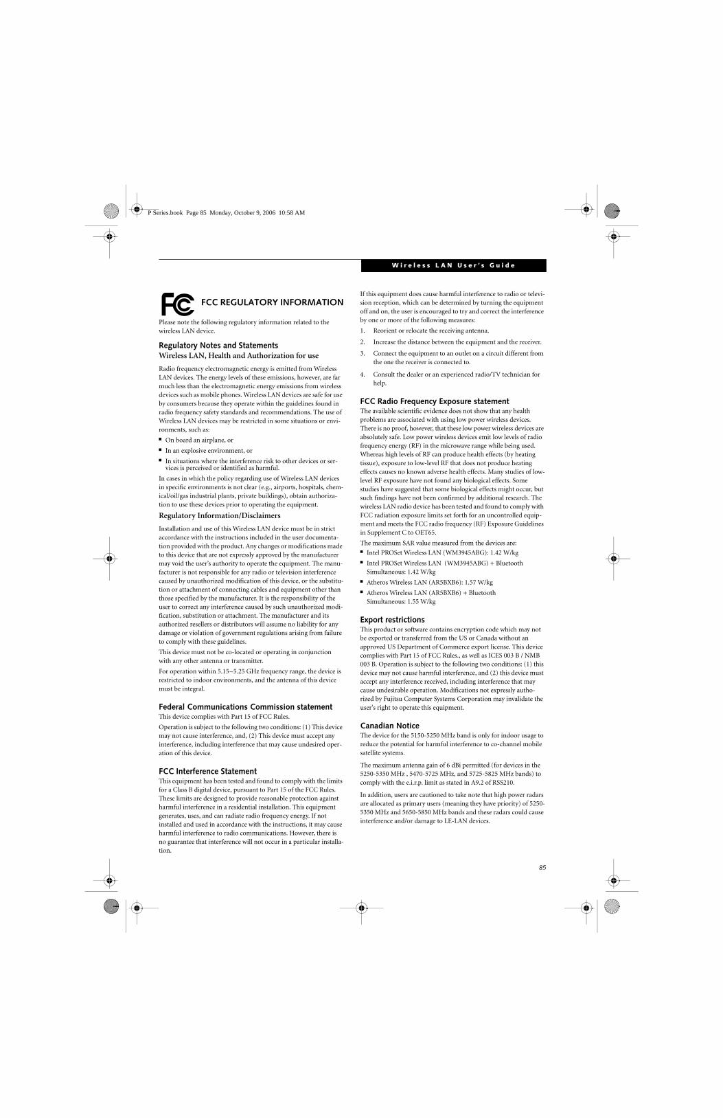
85
W i r e l e s s L A N U s e r ’ s G u i d e
FCC REGULATORY INFORMATION
Please note the following regulatory information related to the wireless LAN device.
Regulatory Notes and StatementsWireless LAN, Health and Authorization for use
Radio frequency electromagnetic energy is emitted from Wireless LAN devices. The energy levels of these emissions, however, are far much less than the electromagnetic energy emissions from wireless devices such as mobile phones. Wireless LAN devices are safe for use by consumers because they operate within the guidelines found in radio frequency safety standards and recommendations. The use of Wireless LAN devices may be restricted in some situations or envi-ronments, such as:■ On board an airplane, or■ In an explosive environment, or■ In situations where the interference risk to other devices or ser-
vices is perceived or identified as harmful.
In cases in which the policy regarding use of Wireless LAN devices in specific environments is not clear (e.g., airports, hospitals, chem-ical/oil/gas industrial plants, private buildings), obtain authoriza-tion to use these devices prior to operating the equipment.
Regulatory Information/Disclaimers
Installation and use of this Wireless LAN device must be in strict accordance with the instructions included in the user documenta-tion provided with the product. Any changes or modifications made to this device that are not expressly approved by the manufacturer may void the user’s authority to operate the equipment. The manu-facturer is not responsible for any radio or television interference caused by unauthorized modification of this device, or the substitu-tion or attachment of connecting cables and equipment other than those specified by the manufacturer. It is the responsibility of the user to correct any interference caused by such unauthorized modi-fication, substitution or attachment. The manufacturer and its authorized resellers or distributors will assume no liability for any damage or violation of government regulations arising from failure to comply with these guidelines.
This device must not be co-located or operating in conjunction with any other antenna or transmitter.
For operation within 5.15~5.25 GHz frequency range, the device is restricted to indoor environments, and the antenna of this device must be integral.
Federal Communications Commission statementThis device complies with Part 15 of FCC Rules.
Operation is subject to the following two conditions: (1) This device may not cause interference, and, (2) This device must accept any interference, including interference that may cause undesired oper-ation of this device.
FCC Interference StatementThis equipment has been tested and found to comply with the limits for a Class B digital device, pursuant to Part 15 of the FCC Rules. These limits are designed to provide reasonable protection against harmful interference in a residential installation. This equipment generates, uses, and can radiate radio frequency energy. If not installed and used in accordance with the instructions, it may cause harmful interference to radio communications. However, there is no guarantee that interference will not occur in a particular installa-tion.
If this equipment does cause harmful interference to radio or televi-sion reception, which can be determined by turning the equipment off and on, the user is encouraged to try and correct the interference by one or more of the following measures:
1. Reorient or relocate the receiving antenna.
2. Increase the distance between the equipment and the receiver.
3. Connect the equipment to an outlet on a circuit different from the one the receiver is connected to.
4. Consult the dealer or an experienced radio/TV technician for help.
FCC Radio Frequency Exposure statementThe available scientific evidence does not show that any health problems are associated with using low power wireless devices. There is no proof, however, that these low power wireless devices are absolutely safe. Low power wireless devices emit low levels of radio frequency energy (RF) in the microwave range while being used. Whereas high levels of RF can produce health effects (by heating tissue), exposure to low-level RF that does not produce heating effects causes no known adverse health effects. Many studies of low-level RF exposure have not found any biological effects. Some studies have suggested that some biological effects might occur, but such findings have not been confirmed by additional research. The wireless LAN radio device has been tested and found to comply with FCC radiation exposure limits set forth for an uncontrolled equip-ment and meets the FCC radio frequency (RF) Exposure Guidelines in Supplement C to OET65.
The maximum SAR value measured from the devices are:■ Intel PROSet Wireless LAN (WM3945ABG): 1.42 W/kg■ Intel PROSet Wireless LAN (WM3945ABG) + Bluetooth
Simultaneous: 1.42 W/kg■ Atheros Wireless LAN (AR5BXB6): 1.57 W/kg■ Atheros Wireless LAN (AR5BXB6) + Bluetooth
Simultaneous: 1.55 W/kg
Export restrictionsThis product or software contains encryption code which may not be exported or transferred from the US or Canada without an approved US Department of Commerce export license. This device complies with Part 15 of FCC Rules., as well as ICES 003 B / NMB 003 B. Operation is subject to the following two conditions: (1) this device may not cause harmful interference, and (2) this device must accept any interference received, including interference that may cause undesirable operation. Modifications not expressly autho-rized by Fujitsu Computer Systems Corporation may invalidate the user's right to operate this equipment.
Canadian NoticeThe device for the 5150-5250 MHz band is only for indoor usage to reduce the potential for harmful interference to co-channel mobile satellite systems.
The maximum antenna gain of 6 dBi permitted (for devices in the 5250-5350 MHz , 5470-5725 MHz, and 5725-5825 MHz bands) to comply with the e.i.r.p. limit as stated in A9.2 of RSS210.
In addition, users are cautioned to take note that high power radars are allocated as primary users (meaning they have priority) of 5250-5350 MHz and 5650-5850 MHz bands and these radars could cause interference and/or damage to LE-LAN devices.
P Series.book Page 85 Monday, October 9, 2006 10:58 AM

86
L i f e B o o k P 1 6 0 0 S e r i e s N o t e b o o k
Before Using the Wireless LANThis manual describes the procedures required to prop-erly setup and configure the integrated Wireless LAN Mini-PCI device (referred to as "WLAN device" in the rest of the manual). Before using the WLAN device, read this manual carefully to ensure it's correct operation. Keep this manual in a safe place for future reference.
Wireless LAN Devices Covered by this Document
This document is applicable to systems containing one of the following two devices. Most of the procedures are identical. Sections that differ between the three devices have been noted in the text:
■ Intel PRO/Wireless 3945ABG Network Connections (WM3945ABG) Network Connections
■ Atheros AR5006EXS Mini-Card wireless network card (AR5BXB6)
Characteristics of the WLAN Device■ The WLAN device is a Mini-PCI card attached to the
main board of the mobile computer.
■ The WLAN devices operate in license-free RF bands, eliminating the need to procure an FCC license to operate. Both WLAN devices operate in the 2.4GHz Industrial, Scientific, and Medical (ISM) RF band and the lower and middle bands of the 5GHz Unlicensed National Information Infrastructure (UNII) bands.
■ The Intel PRO/Wireless 2915ABG and Atheros AR5002X WLAN devices are capable of three operat-ing modes: IEEE 802.11a, IEEE 802.11b and IEEE 802.11g.
■ Encoding of data is modulated using Direct Sequence Spread Spectrum (DSSS) and Complementary Code Keying (CCK) when the WLAN device is operating in IEEE 802.11b mode and Orthogonal Frequency Divi-sion Multiplexing (OFDM) when operating in IEEE 802.11a or IEEE 802.11g mode.
■ The WLAN device is Wi-Fi certified and operates at the maximum data transfer rate of 54 Mbps in IEEE 802.11a or IEEE 802.11g mode and 11 Mbps in IEEE 802.11b mode.
■ The WLAN device supports the following encryption methods - WEP, CKIP, TKIP, and AES encryption.
WIRELESS LAN MODES USING THIS DEVICE
Ad Hoc Mode
(See Figure A-1)
"Ad Hoc Mode" refers to a wireless network architecture where wireless network connectivity between multiple computers is established without a central wireless network device, typically known as Access Point(s). Connectivity is accomplished using only client devices in a peer-to-peer fashion. That is why Ad Hoc networks are also known as peer-to-peer networks. Ad Hoc networks are an easy and inexpensive method for establishing network connectivity between multiple computers.
Ad Hoc mode requires that the SSID, network authenti-cation, and encryption key settings are identically configured on all computers in the Ad Hoc network.
Figure A-1. Ad Hoc Mode Network
P Series.book Page 86 Monday, October 9, 2006 10:58 AM

87
W i r e l e s s L A N U s e r ’ s G u i d e
Access Point (Infrastructure) Mode
(See Figure A-2)
Infrastructure mode refers to a wireless network archi-tecture in which devices communicate with wireless or wired network devices by communicating through an Access Point. In infrastructure mode, wireless devices can communicate with each other or can communicate with a wired network. Corporate wireless networks operate in infrastructure mode because they require access to the wired LAN in order to access computers, devices, and services such as file servers, printers, and databases.
How to Handle This Device
The WLAN device comes pre-installed in your mobile computer. Under normal circumstances, it should not be necessary for you to remove or re-install it. The Oper-ating System that your mobile computer comes with has been pre-configured to support the WLAN device.
WIRELESS NETWORK CONSIDERATIONS
■ The WLAN devices support IEEE 802.11a, IEEE 802.11b and IEEE 802.11g.
■ The WLAN devices operate in the 2.4GHz ISM band and the 5 GHz lower, middle, and upper UNII bands.
■ Microwave ovens will interfere with the operation of WLAN device as microwave ovens operate in the same 2.4GHz frequency range that IEEE 802.11b/g devices operate in. Interference by microwaves does not occur with IEEE 802.11a radio which operates in the 5 GHz RF band.
■ Wireless devices that transmit in the 2.4GHz fre-quency range may interfere with the operation of WLAN devices in IEEE 802.11b/g modes. Symptoms of interference include reduced throughput, intermit-tent disconnects, and large amounts of frame errors. It is HIGHLY recommended that these interfering devices be powered off to ensure the proper operation of the WLAN device.
DEACTIVATING THE WLAN DEVICEDeactivation of the WLAN device may be desired in certain circumstances (to extend battery life) or where certain environments require it (i.e. hospitals, clinics, airplanes, etc.). Fujitsu mobile computers employ two methods with which to deactivate the WLAN device:
■ Using the Wireless On/Off Switch
■ In Windows, using the Intel PROSet Software or Atheros Client Utility software.
Figure A-2. Access Point (Infrastructure) Mode Network
ADSL modem,cable modem,or similar
Internet Wired LAN
Access Point*
Wireless LAN
*An optional hub for a wiredLAN may be required dependingupon the type of access point used.
P Series.book Page 87 Monday, October 9, 2006 10:58 AM
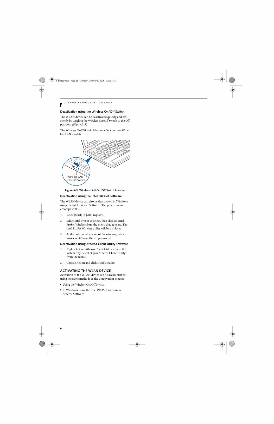
88
L i f e B o o k P 1 6 0 0 S e r i e s N o t e b o o k
Deactivation using the Wireless On/Off Switch
The WLAN device can be deactivated quickly and effi-ciently by toggling the Wireless On/Off Switch to the Off position. (Figure A-3)
The Wireless On/Off switch has no effect on non-Wire-less LAN models.
Figure A-3. Wireless LAN On/Off Switch Location
Deactivation using the Intel PROSet Software
The WLAN device can also be deactivated in Windows using the Intel PROSet Software. The procedure to accomplish this:
1. Click [Start]-> [All Programs].
2. Select Intel ProSet Wireless, then click on Intel ProSet Wireless from the menu that appears. The Intel ProSet Wireless utility will be displayed.
3. At the bottom left corner of the window, select Wireless Off from the dropdown list.
Deactivation using Atheros Client Utility software
1. Right-click on Atheros Client Utility icon in the system tray. Select “Open Atheros Client Utility” from the menu.
2. Choose Action and click Disable Radio.
ACTIVATING THE WLAN DEVICEActivation of the WLAN device can be accomplished using the same methods as the deactivation process
■ Using the Wireless On/Off Switch
■ In Windows using the Intel PROSet Software or Atheros Software
Wireless LANOn/Off Switch
P Series.book Page 88 Monday, October 9, 2006 10:58 AM

89
W i r e l e s s L A N U s e r ’ s G u i d e
Configuration of the WLAN Device
The WLAN Device can be configured to establish wire-less network connectivity using one of the following tools:
■ Intel PROSet Software - The Intel PROSet Software allows for multiple profile setup and supports auto-matic profile switching. Support for most industry standard security solutions is contained in this soft-ware.
■ Atheros Client Utility - The Atheros Client Utility soft-ware allows for multiple profile setups and supports automatic profile switching. Support for most indus-try standard security solutions is contained in this software.
FLOW OF OPERATIONS1. Activate the WLAN Device (See Activating the
WLAN Device on page 88 for more information).
2. Configure the Wireless Network parameters.
■ Enter the network name (SSID)
■ Choose the appropriate WLAN architecture (Ad Hoc or Infrastructure)
■ Choose Authentication method: Open, Shared, WPA-Enterprise, WPA2-Enterprise, WPA-Personal, or WPA2-Personal
■ If using static WEP keys, enter static WEP key and choose key index.
3. Configure network settings (See Configure Net-work Parameters on page 89 for more information)
■ TCP/IP settings
■ Workgroup or Domain settings.
CONFIGURATION USING INTEL PROSET SOFTWAREThis section explains the procedure to properly configure the WLAN device using the Intel PROSet Soft-ware. Pre-defined parameters will be required for this procedure. Please consult with your network adminis-trator for these parameters:
Network Name - Also known as the SSID
Network Key (WEP) - Required if using static WEP keys.
Authentication Type - Open, Shared, WPA, or WPA-PSK
Procedure
1. Activate the WLAN device using either the Wireless On/Off Switch or the Intel PROSet software.
2. Click the [Start] button first and then [All Pro-grams].
3. Click the icon [Intel PROSet Wireless] to execute the Intel PROSet Wireless software.
4. Click the [Add] button. The General Settings dialog displays.
5. Enter a profile name in the Profile Name field.
6. Enter the network SSID, in the Network Name (SSID) field.
7. Click Infrastructure or Ad Hoc for the operating mode.
8. Click [Advanced].
9. The Mandatory Access Point option is only used if Infrastructure mode is selected. Use this option to connect to a specific access point. Enter the MAC address for the access point. Click OK to save the setting and return to the General Settings page.
10. Click [Next].
11. If you are using Cisco CCX, click Cisco Options to enable Cisco CKIP data encryption on the Security Settings page. Check the Cisco Compatible Exten-sions Options. If you have checked the Cisco's "Mixed-Cell" box in the Advanced Setting, this option must also be checked.
12. Click [OK].
13. Click Next.
14. Select Open, Shared, WPA-Enterprise, WPA2-Enterprise, WPA-Personal, or WPA2-Personal in the Network Authentication options.
15. Select either None, WEP, CKIP (if Enable Cisco Cli-ent eXtentions is enabled, use CKIP or WEP), or TKIP for the data encryption.
16. If WEP is selected, select either 64 or 128-bit for the Encryption Level.
17. Select the key index 1, 2, 3 or 4.
18. Enter the WEP key if required. If your network does not employ a 802.1x/EAP security mechanism, please skip to step 24.
P Series.book Page 89 Monday, October 9, 2006 10:58 AM

90
L i f e B o o k P 1 6 0 0 S e r i e s N o t e b o o k
19. Click the Enable 802.1x checkbox to enable the 802.1x security option. Please contact your network administrator if configuration of this setting is required.
20. Select the appropriate Authentication Type. Please contact your network administrator if configura-tion of this setting is required.
21. After selecting your authentication type, enter the user name, domain, and password of the user you have created on the authentication server. The user name and password do not have to be the same as name and password of your current Windows user login.
22. Click [OK] to save the settings.
23. From the Intel ProSet Wireless page, click the new profile name shown in the Profile List. Use the up and down arrows to position the priority of the new profile in the priority list.
24. Click the Connect button to connect to the net-work.
25. Click [Close] if you want to close the Intel(R) PROSet for Wireless window.
CONFIGURATION USING ATHEROS CLIENT UTILITY SOFTWAREThis section explains the procedure to properly configure the WLAN device using the Atheros Client Utility. Pre-defined parameters will be required for this procedure. Please consult with your network adminis-trator for these parameters:
Network Name - Also known as the SSID
Network Key (WEP) - Required if using static WEP keys.
Authentication Type - Open, Shared, WPA, or WPA-PSK
Procedure
1. Activate the WLAN device using either the Wireless On/Off Switch or the Atheros Client Utility
2. Right-click on the “Atheros Client Utility” icon in the system tray, and select “Open Atheros Client Utility” from the menu.
3. From the Current Status page, click the Profile Management tab.
4. If this is your first time using this utility, highlight the profile [Default] and Click the [Modify] button, otherwise Click the [New] button. The General Set-tings dialog displays.
5. From the General page, enter a profile name in the Profile Name field.
6. Enter the network SSID, in the SSID1 field. If you wish to create a profile that can connect to up to 3 different wireless networks, SSID's can be entered in the SSID2 and SSID3 fields as well.
7. Click the Security tab.
8. The Security tab allows for the configuration of the Security modes listed in the table below. Please select the radio button of the desired security mode. If these settings are not known to you, please consult with your network administrator for the correct settings.
9. Click OK
10. Click the Advanced tab
11. The Advanced tab allows for the configuration of the options detailed in the table below
Field Name Description
WPA Enables the use of Wi-Fi Protected Access. Choosing WPA opens the WPA EAP drop-down menu. Options include TLS and PEAP. If these settings are not known to you, please consult with your network administrator for the correct settings.
WPA-PSK Enables WPA-Pre-Shared Key. Click on the Configure button to enter the WPA Passphrase. If these settings are not known to you, please consult with your network administrator for the correct settings.
802.1x Enables 802.1x security. If these settings are not known to you, please consult with your network administrator for the correct settings. Choosing this option opens the 802.1x EAP type drop-down menu. Options include TLS, PEAP, and LEAP
Pre-Shared Key Enables the use of pre-shared keys that are defined on both the access point and the station. This is where static WEP keys are entered. Click the Configure button to fill in the Define Pre-Shared Keys window.
None No security
P Series.book Page 90 Monday, October 9, 2006 10:58 AM

91
W i r e l e s s L A N U s e r ’ s G u i d e
.
12. Click OK
13. If the profile you just created does not activate immediately, click the Profile Management tab, highlight the desired Profile, and click Activate.
14. Click [Close] if you want to close the Atheros Client Utility.
CONNECTION TO THE NETWORKThis section explains connection to the network.
If there is an administrator of the network, contact the network administrator for data settings.
Setting the network
Perform the “Setting TCP/IP” and “Confirming the computer and work group names” operations required for network connection.
Setting TCP/IP
1. Click the [Start] button first and then [Control Panel].
2. If the Control Panel is in Category view, switch to Classic view by clicking “Switch to Classic View”
under Control Panel the left frame. (If you are already in Classic view, “Switch to Category View” will be displayed.)
3. Double-click [Network Connections]. A list of cur-rently installed networks will be displayed.
4. Right-click [Wireless Network Connection] in the list, and then click [Properties] in the menu dis-played. The [Wireless Network Connection Proper-ties] window will be displayed.
5. Click the [General] tab if it is not already selected.
6. Click [Internet Protocol (TCP/IP] and then click [Properties]. The [Internet Protocol (TCP/IP) Properties] window will be displayed.
7. Set the IP address as follows:
■ For ad hoc connection: Select [Use the following IP address:] and then enter data for [IP address] and [Subnet mask]. See page 98 for IP address setting.
■ For access point (infrastructure) connection: If your network uses DHCP, select [Obtain an IP address automatically] and [Obtain DNS server address automatically]. If your network uses static IP addresses, consult with your network adminis-trator for the correct IP address settings.
8. Click the [OK] button. Processing will return to the [Wireless Network Connection Properties] window.
9. Click the [OK] button.
10. Close the [Network Connection] window.
Following this operation, confirm the names of the computer and the workgroup as follows.
Confirming the computer and work group names
1. Click the [Start] button, then [Control Panel].
2. If the Control Panel is in Category view, switch to Classic view by clicking “Switch to Classic View” under Control Panel the left frame. (If you are already in Classic view, “Switch to Category View” will be displayed.)
3. Double-click the [System] icon. The [System Prop-erties] window will be displayed.
4. Click the [Computer Name] tab.
Field Name Description
Power Save Mode
Options are Maximum, Normal, or Off
Network Type Options are AP (Infrastructure) or Ad Hoc
802.11b Preamble
Specifies the preamble setting in 802.11b. The default setting is Short and Long (Access Point mode), which allows both short and long headers in the 802.11b frames. Set to Long Only to override allowing short frames.
Transmit Power Level
Options are selectable, depending upo whether 802.11b/g or 802.11a is used.
Wireless Mode Specifies 5 GHz 54 Mbps, 2.4 GHz 11 Mbps, or 2.4 GHz 54 Mbps oper-ation in an access point network.
Wireless Mode when Starting Ad Hoc Network
Specifies 5GHz 54 Mbps, 2.4 GHz 11 Mbps, or 2.4 GHz 54 Mbps to start an Ad Hoc network if no matching network name is found after scan-ning all available modes.
To change the setting of the IP address, you need to be logged in from Windows as an administrator.
To modify the computer name and/or the work group name, you need to be logged in from Windows as an administrator.
P Series.book Page 91 Monday, October 9, 2006 10:58 AM

92
L i f e B o o k P 1 6 0 0 S e r i e s N o t e b o o k
5. Confirm the settings of [Full computer name:] and [Workgroup:].
a. The setting of [Full computer name:] denotes the name for identifying the computer. Any name can be assigned for each personal computer.
Enter the desired name in less than 15 ASCII character code format. Identifiability can be enhanced by entering the model number, the user name, and other factors.
b. [Workgroup name] is the group name of the network. Enter the desired name in less than 15 ASCII character code format.
For ad hoc connection: Assign the same network name to all personal computers existing on the network.
For access point (infrastructure) connection: Assign the name of the work group to be accessed.
6. Click the [OK] button. If a message is displayed that requests you to restart the personal computer, click [Yes] to restart the computer.
Setting the sharing function
Set the sharing function to make file and/or printer sharing with other network-connected personal computers valid.
This operation is not required unless the sharing func-tion is to be used.
The folder and printer for which the sharing function has been set will be usable from any personal computer present on the network.
Setting the Microsoft network-sharing service
1. Click the [Start] button first and then [Control Panel].
2. If the Control Panel is in Category view, switch to Classic view by clicking “Switch to Classic View” under Control Panel the left frame. (If you are already in Classic view, “Switch to Category View” will be displayed.)
3. Double-click [Network Connections]. A list of cur-rently installed networks will be displayed.
4. Right-click [Wireless Network Connection] in the list, and then click [Properties] in the menu dis-played. The [Wireless Network Connection Proper-ties] window will be displayed.
5. If [File and Printer Sharing for Microsoft Net-works] is displayed, proceed to step 6. If [File and Printer Sharing for Microsoft Networks] is not dis-played, skip to step 7.
6. Make sure that the [File and Printer Sharing for Microsoft Networks] check box is checked, and then click the [OK] button. Skip to “Setting file-sharing function”.
7. Click [Install]. The [Select Network Component Type] window will be displayed.
8. Click [Service], then click the [Add] button. The [Select Network Service] window will be displayed.
9. Click [File and Printer Sharing for Microsoft Net-works] and then click the [OK] button. Processing will return to the [Wireless Network Connection Properties] window, and [File and Printer Sharing for Microsoft Networks] will be added to the list.
10. Click the [Close] button.
Setting the file-sharing function
The procedure for setting the file-sharing function follows, with the “work” folder in drive C: as an example.
1. Click the [Start] button first and then [My Com-puter].
2. Double-click [Local disk (C:)].
3. Right-click the “work” folder (or whichever folder you want to share), and then click [Sharing and Security...] in the menu displayed. The [Folder
Name Properties] window will be displayed.
4. Click [Sharing] if it isn’t already selected.
To change the name, click [Change] and then proceed in accordance with the instruction messages displayed on the screen.
To share a file and/or the connected printer, you need to be logged in as an administrator. Setting the file-sharing function for the file
which has been used to execute Network Setup Wizard is suggested on the screen. For the wireless LAN, however, since security is guaranteed by entry of the network name (SSID) and the network key, the steps to be taken to set the file-sharing function easily without using Network Setup Wizard are given below.
P Series.book Page 92 Monday, October 9, 2006 10:58 AM
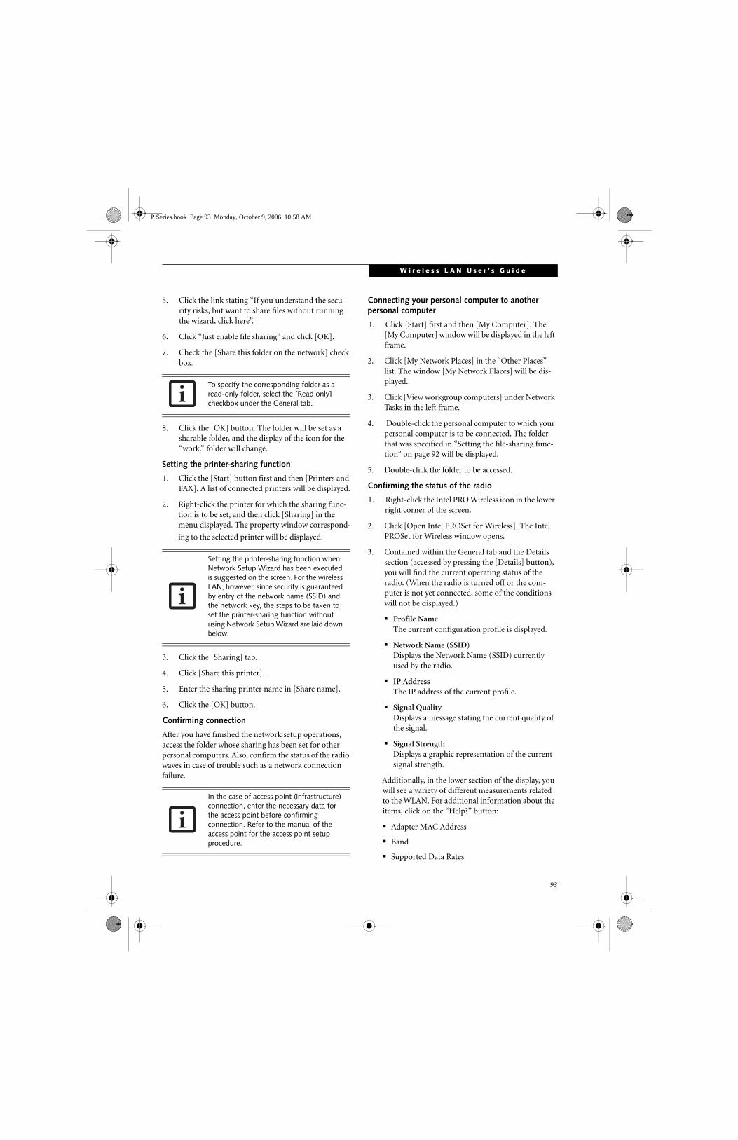
93
W i r e l e s s L A N U s e r ’ s G u i d e
5. Click the link stating “If you understand the secu-rity risks, but want to share files without running the wizard, click here”.
6. Click “Just enable file sharing” and click [OK].
7. Check the [Share this folder on the network] check box.
8. Click the [OK] button. The folder will be set as a sharable folder, and the display of the icon for the “work.” folder will change.
Setting the printer-sharing function
1. Click the [Start] button first and then [Printers and FAX]. A list of connected printers will be displayed.
2. Right-click the printer for which the sharing func-tion is to be set, and then click [Sharing] in the menu displayed. The property window correspond-
ing to the selected printer will be displayed.
3. Click the [Sharing] tab.
4. Click [Share this printer].
5. Enter the sharing printer name in [Share name].
6. Click the [OK] button.
Confirming connection
After you have finished the network setup operations, access the folder whose sharing has been set for other personal computers. Also, confirm the status of the radio waves in case of trouble such as a network connection failure.
Connecting your personal computer to another personal computer
1. Click [Start] first and then [My Computer]. The [My Computer] window will be displayed in the left frame.
2. Click [My Network Places] in the “Other Places” list. The window [My Network Places] will be dis-played.
3. Click [View workgroup computers] under Network Tasks in the left frame.
4. Double-click the personal computer to which your personal computer is to be connected. The folder that was specified in “Setting the file-sharing func-tion” on page 92 will be displayed.
5. Double-click the folder to be accessed.
Confirming the status of the radio
1. Right-click the Intel PRO Wireless icon in the lower right corner of the screen.
2. Click [Open Intel PROSet for Wireless]. The Intel PROSet for Wireless window opens.
3. Contained within the General tab and the Details section (accessed by pressing the [Details] button), you will find the current operating status of the radio. (When the radio is turned off or the com-puter is not yet connected, some of the conditions will not be displayed.)
■ Profile NameThe current configuration profile is displayed.
■ Network Name (SSID)Displays the Network Name (SSID) currently used by the radio.
■ IP AddressThe IP address of the current profile.
■ Signal QualityDisplays a message stating the current quality of the signal.
■ Signal StrengthDisplays a graphic representation of the current signal strength.
Additionally, in the lower section of the display, you will see a variety of different measurements related to the WLAN. For additional information about the items, click on the “Help?” button:
■ Adapter MAC Address
■ Band
■ Supported Data Rates
To specify the corresponding folder as a read-only folder, select the [Read only] checkbox under the General tab.
Setting the printer-sharing function when Network Setup Wizard has been executed is suggested on the screen. For the wireless LAN, however, since security is guaranteed by entry of the network name (SSID) and the network key, the steps to be taken to set the printer-sharing function without using Network Setup Wizard are laid down below.
In the case of access point (infrastructure) connection, enter the necessary data for the access point before confirming connection. Refer to the manual of the access point for the access point setup procedure.
P Series.book Page 93 Monday, October 9, 2006 10:58 AM

94
L i f e B o o k P 1 6 0 0 S e r i e s N o t e b o o k
■ Radio Frequency
■ Channel Number
■ Network Authentication
■ Data Encryption
■ 802.1x Authentication Type
■ 802.1x Authentication Protocol
■ CCX Version
■ CCX TPC
■ CCX Power Levels
■ Access Point MAC Address
■ Mandatory Access Point
P Series.book Page 94 Monday, October 9, 2006 10:58 AM
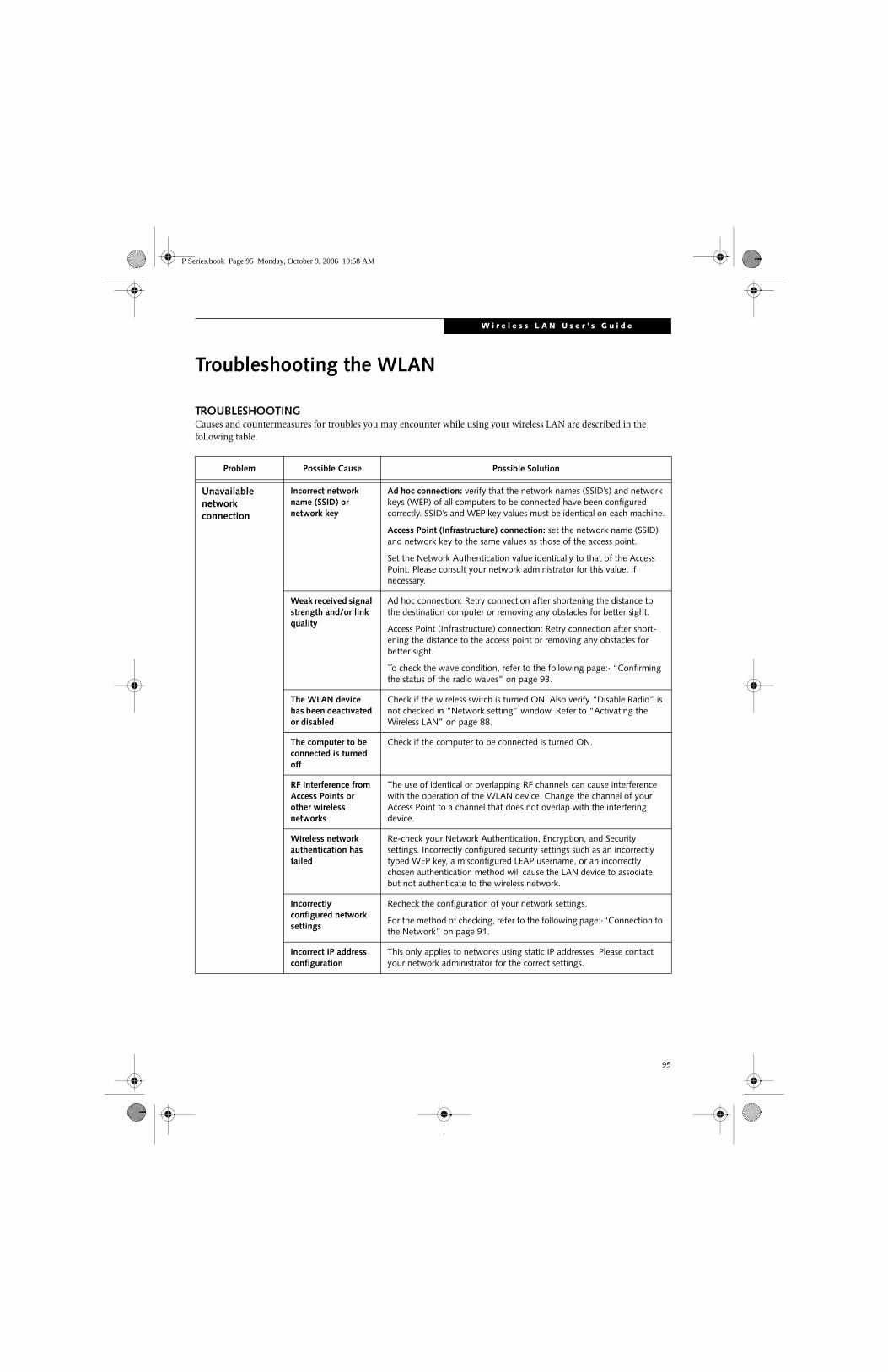
95
W i r e l e s s L A N U s e r ’ s G u i d e
Troubleshooting the WLAN
TROUBLESHOOTINGCauses and countermeasures for troubles you may encounter while using your wireless LAN are described in the following table.
Problem Possible Cause Possible Solution
Unavailable network connection
Incorrect network name (SSID) or network key
Ad hoc connection: verify that the network names (SSID’s) and network keys (WEP) of all computers to be connected have been configured correctly. SSID’s and WEP key values must be identical on each machine.
Access Point (Infrastructure) connection: set the network name (SSID) and network key to the same values as those of the access point.
Set the Network Authentication value identically to that of the Access Point. Please consult your network administrator for this value, if necessary.
Weak received signal strength and/or link quality
Ad hoc connection: Retry connection after shortening the distance to the destination computer or removing any obstacles for better sight.
Access Point (Infrastructure) connection: Retry connection after short-ening the distance to the access point or removing any obstacles for better sight.
To check the wave condition, refer to the following page:· “Confirming the status of the radio waves” on page 93.
The WLAN device has been deactivated or disabled
Check if the wireless switch is turned ON. Also verify “Disable Radio” is not checked in “Network setting” window. Refer to “Activating the Wireless LAN” on page 88.
The computer to be connected is turned off
Check if the computer to be connected is turned ON.
RF interference from Access Points or other wireless networks
The use of identical or overlapping RF channels can cause interference with the operation of the WLAN device. Change the channel of your Access Point to a channel that does not overlap with the interfering device.
Wireless network authentication has failed
Re-check your Network Authentication, Encryption, and Security settings. Incorrectly configured security settings such as an incorrectly typed WEP key, a misconfigured LEAP username, or an incorrectly chosen authentication method will cause the LAN device to associate but not authenticate to the wireless network.
Incorrectly configured network settings
Recheck the configuration of your network settings.
For the method of checking, refer to the following page:·“Connection to the Network” on page 91.
Incorrect IP address configuration
This only applies to networks using static IP addresses. Please contact your network administrator for the correct settings.
P Series.book Page 95 Monday, October 9, 2006 10:58 AM

96
L i f e B o o k P 1 6 0 0 S e r i e s N o t e b o o k
Wireless LAN Glossary
GLOSSARY
Access point
Wireless network device used to bridge wireless and wired network traffic.
Ad Hoc Mode
Ad Hoc Mode refers to a wireless network architecture where wireless network connectivity between multiple computers is established without a central wireless network device, typically known as Access Points. Connectivity is accomplished using only client devices in a peer-to-peer fashion. For details, refer to “Ad hoc connection” on page 86.
CCX (Cisco Compatible Extensions)
Implementation that provides improved wireless data security, ensuring certified compatibility with Cisco wireless access points.
Channel
Range of narrow-band frequencies used by the WLAN device to transmit data. IEEE 802.11b/g - 11 channels, 22 MHz wide channels.
DHCP (Dynamic Host Configuration Protocol)
A protocol that provides a means to dynamically allocate IP addresses to computers on a local area network.
DNS (Domain Name System)
A data query service that provides a mechanism with which to translate host names into Internet addresses.
EAP
Extensible Authentication ProtocolA protocol implementation that provides a framework to allow easier user authentication.
IEEE 802.11a
Wireless LAN standard that supports a maximum data rate of 54 Mbps. 802.11a devices operate in the 5 GHz lower and middle UNII bands.
IEEE 802.11b
Wireless LAN standard that supports a maximum data rate of 11 Mbps. 802.11b devices operate in the 2.4 GHz ISM band.
IP address
The logical 32-bit host address defined by the Internet Protocol that uniquely identifies a computer on a network. The IP address is usually expressed in dotted decimal notation.
LAN (Local Area Network)
A LAN or Local Area Network is a computer network (or data communications network) which is confined to a limited geographical area.
MAC address (Media Access Control Address)
A MAC address (also called an Ethernet address or IEEE MAC address) is the 48-bit address (typically written as twelve hexadecimal digits, 0 through 9 and A through F, or as six hexadecimal numbers separated by periods or colons, e.g., 0080002012ef, 0:80:0:2:20:ef) which uniquely identifies a computer that has an Ethernet interface.
MTU (Maximum Transmission Unit)
The maximum size of data which can be transmitted at one time in networks including the Internet. In an envi-ronment whose maximum size of data is too large to correctly receive data, normal communications can be restored by setting the size of MTU to a smaller value.
Network key
Data that is used for encrypting data in data communi-cation. The personal computer uses the same network key both for data encryption and decryption, therefore, it is necessary to set the same network key as the other side of communication.
Network name (SSID: Security Set Identifier)
When a wireless LAN network is configured, grouping is performed to avoid interference or data theft. This grouping is performed with “Network name (SSID)”. In order to improve security, the network key is set allowing no communication unless “Network name (SSID)” coincides with the network key.
Open system authentication
Null authentication method specified in the 802.11 stan-dard that performs no authentication checks on a wire-less client before allowing it to associate.
P Series.book Page 96 Monday, October 9, 2006 10:58 AM

97
W i r e l e s s L A N U s e r ’ s G u i d e
PEAP (Protected Extensible Authentication Protocol)
An improvement over EAP, making authentication much easier to achieve.
PPPoE (Point to Point Protocol over Ethernet)
A method of allowing the authentication protocol adopted in telephone line connection (PPP) to be used over an Ethernet.
Protocol
A procedure or rule of delivering data among computers. Ordered data communication is allowed by making all conditions required for communication including the method of data transmission/reception and actions upon communication errors into proce-dures.
Shared key authentication
802.11 network authentication method in which the AP sends the client device a challenge text packet that the client must then encrypt with the correct WEP key and return to the AP. If the client has the wrong key or no key, authentication will fail and the client will not be allowed to associate with the AP. Shared key authentica-tion is not considered secure, because a hacker who detects both the clear-text challenge and the same chal-lenge encrypted with a WEP key can decipher the WEP key.
SSID (Service Set Identifier)
Service Set Identifier, a 32-character unique identifier attached to the header of packets sent over a WLAN that acts as a password when a mobile device tries to connect to the BSS. The SSID differentiates one WLAN from another, so all access points and all devices attempting to connect to a specific WLAN must use the same SSID. A device will not be permitted to join the BSS unless it can provide the unique SSID. Because the SSID is broadcast in plain text, it does not supply any security to the network.
Subnet mask
TCP-IP network is controlled by being divided into multiple smaller networks (subnets). IP address consists of the subnet address and the address of each computer. Subnet mask defines how many bits of IP address comprise the subnet address. The same value shall be set among computers communicating with each other.
TCP/IP (Transmission Control Protocol/Internet Protocol)
A standard protocol of the Internet.
TKIP (Temporal Key Integrity Protocol)
Security feature that is a WEP enhancement to defend against known wireless data security issues.
WEP (Wired Equivalent Privacy)
Standard wireless security provided by the Wi-Fi stan-dard, used for protecting wireless data.
Wi-Fi
Wi-Fi, or Wireless Fidelity, is a set of standards for wire-less local area networks (WLAN) based on the IEEE 802.11 specifications. Certified products can use the official Wi-Fi logo, which indicates that the product is interoperable with any other product also showing that logo.
WPA (Wi-Fi Protected Access)
Strong replacement for WEP, providing improved data encryption and user authentication.
P Series.book Page 97 Monday, October 9, 2006 10:58 AM

98
L i f e B o o k P 1 6 0 0 S e r i e s N o t e b o o k
IP address information
ABOUT IP ADDRESSES
If IP address is unknown, set IP address as follows:
If you have an access point (DHCP server) on the network, set the IP address as follows:
[Obtain an IP address automatically]
If the IP address is already assigned to the computer in the network, ask the network administrator to check the IP address to be set for the computer.
If no access point is found in the network:
An IP address is expressed with four values in the range between 1 and 255.
Set the each computer as follows: The value in paren-theses is a subnet mask.
<Example>
Computer A: 192.168.100.2 (255.255.255.0)
Computer B: 192.168.100.3 (255.255.255.0)
Computer C: 192.168.100.4 (255.255.255.0)
:
:
Computer X: 192.168.100.254 (255.255.255.0)
IP addressing is much more complicated than can be briefly explained in this document. You are advised to consult with your network administrator for additional information.
A DHCP server is a server that automatically assigns IP addresses to computers or other devices in the network. There is no DHCP server for the AdHoc network.
P Series.book Page 98 Monday, October 9, 2006 10:58 AM

99
W i r e l e s s L A N U s e r ’ s G u i d e
Specifications
* “Wi-Fi based” indicates that the interconnectivity test of the organization which guarantees the interconnectivity of wireless LAN (Wi-Fi Alliance) has been passed.
** The communication ranges shown above will increase or decrease depending on factors such as number of walls, reflective material, or interference from external RF sources.
*** Encryption with network key (WEP) is performed using the above number of bits, however, users can set 40 bits/104 bits after subtracting the fixed length of 24 bits.
**** Depending on practical environments, the allowable number of computers to be connected may be decreased.
Item Specification
Type of network The Atheros AR5006X (AR5BXB6) and the Intel PRO/Wireless 3945ABG (WM3945ABG) Network Connections WLAN devices conform to IEEE 802.11a and 802.11b/g (Wi-Fi based)*.
Transfer rate (Automatic switching)IEEE 802.11a/g: 54 Mbps maximum data rate
IEEE 802.11b: 11 Mbps maximum data rate
Active frequency 802.11b/g: 2400~2473 MHz 802.11a: 5050 ~ 5850 MHz
Number of channels 802.11a: 8 independent channels802.11b/g: 11 channels, 3 non-overlapping channels
Typical operating distances** 802.11a: 40 ft. (12 m) @ 54 Mbps; 300 ft. (91 m) @ 6 Mbps802.11b: 100 ft. (30 m) @ 11 Mbps; 300 ft. (91 m) @ 1 Mbps802.11g: 100 ft. (30 m) @ 54 Mbps; 300 ft. (91 m) @ 1 Mbps
Security Encryption Types - WEP, TKIP, AES***WPA 1.0 compliant
Encryption key lengths supported: 64 bits, 128 bits, and 152 bits (Atheros module using AES encryption only)
802.1x/EAP
Maximum recommended number of computers to be connected over wireless LAN (during ad hoc connection)
10 units or less ****
P Series.book Page 99 Monday, October 9, 2006 10:58 AM

100
L i f e B o o k P 1 6 0 0 S e r i e s N o t e b o o k
Using the Bluetooth DeviceThe Integrated Bluetooth module (EYTF3CSFT) is an optional device available for Fujitsu mobile computers.
WHAT IS BLUETOOTHBluetooth technology is designed as a short-range wire-less link between mobile devices, such as laptop computers, phones, printers, and cameras. Bluetooth technology is used to create Personal Area Networks (PANs) between devices in short-range of each other.
WHERE TO FIND INFORMATIONABOUT BLUETOOTHThe Bluetooth module contains a robust Help user’s guide to assist you in learning about operation of the Bluetooth device.
To access the Help file, click [Start] -> All Programs, and click on Toshiba. Select Bluetooth, then select User’s Guide.
For additional information about Bluetooth Technology, visit the Bluetooth website at: www.bluetooth.com.
Canadian Notice
To prevent radio interference to the licensed service, this device is intended to be operated indoors and away from windows to provide maximum shielding. Equipment (or its transmit antenna) that is installed outdoors is subject to licensing.
Warranty
Users are not authorized to modify this product. Any modifications invalidate the warranty.
This equipment may not be modified, altered, or changed in any way without signed written permission from Fujitsu. Unauthorized modification will void the equipment authorization from the FCC and Industry Canada and the warranty.
P Series.book Page 100 Monday, October 9, 2006 10:58 AM

101
Appendix BUsing the Fingerprint Swipe Sensor
P Series.book Page 101 Monday, October 9, 2006 10:58 AM

102
L i f e B o o k P 1 6 0 0 S e r i e s N o t e b o o k
P Series.book Page 102 Monday, October 9, 2006 10:58 AM

103
F i n g e r p r i n t S e n s o r U s e r ’ s G u i d e
Fingerprint Sensor DeviceINTRODUCING THE FINGERPRINT SENSOR DEVICEYour system has a fingerprint sensor device in the loca-tion shown in the figure below.
Figure B-1 Fingerprint sensor
With a fingerprint sensor, you can avoid having to enter a username and password every time you want to:
■ Log onto Windows
■ Recover from suspend mode
■ Cancel a password-protected screen saver
■ Log into homepages that require a username and pass-word
After you have “enrolled” - or registered - your finger-print, you can simply swipe your fingertip over the sensor for the system recognize you.
The fingerprint sensor uses Softex OmniPass which provides password management capabilities to Microsoft Windows operating systems. OmniPass enables you to use a “master password” for all Windows, applications, and on-line passwords.
OmniPass requires users to authenticate themselves using the fingerprint sensor before granting access to the Windows desktop. This device results in a secure authentication system for restricting access to your computer, applications, websites, and other password-protected resources.
OmniPass presents a convenient graphical user interface, through which you can securely manage passwords, users, and multiple identities for each user.
GETTING STARTEDThis section guides you through the preparation of your system for the OmniPass fingerprint recognition application. You will be led through the OmniPass installation process. You will also be led through the procedure of enrolling your first user into OmniPass.
INSTALLING OMNIPASSIf OmniPass has already been installed on your system, skip this section and go directly to “User Enrollment” on page 104. You can determine whether OmniPass has already been installed by checking to see if the following are present:
■ The presence of the gold key-shaped OmniPass icon in the system tray at the bottom right of the screen.
■ The presence of the Softex program group in the Programs group of the Start menu
System RequirementsThe OmniPass application requires space on your hard drive; it also requires specific Operating Systems (SO’s). The minimum requirements are as follows:
■ Windows XP Home Edition, Windows XP Profes-sional or Windows 2000 operating system
■ At least 35 MB available hard disk space
Installing the OmniPass ApplicationIf OmniPass is already installed on your system, go to “User Enrollment” on page 104. Otherwise continue with this section on software installation.
To install OmniPass on your system you must:
1. Insert the installation media for the OmniPass appli-cation into the appropriate drive. If you are installing from CD-ROM or DVD-ROM, you must find and launch the OmniPass installation program (setup.exe) from the media.
2. Follow the directions provided in the OmniPass installation program. Specify a location to which you would like OmniPass installed. It is recom-mended that you NOT install OmniPass in the root directory (e.g. C:\).
3. Once OmniPass has completed installation you will be prompted to restart you system. Once your system has rebooted you will be able to use OmniPass. If you choose not to restart immediately after installation, OmniPass will not be available for use until the next reboot.
The installation program automatically places an icon (Softex OmniPass) in the Windows Control Panel as well as a golden key shaped icon in the taskbar.
Fingerprint Recognition Sensor
For installation, OmniPass requires that the user installing OmniPass have administrative privileges to the system. If your current user does not have administrative privileges, log out and then log in with an administrator user before proceeding with OmniPass installation.
P Series.book Page 103 Monday, October 9, 2006 10:58 AM
104
L i f e B o o k P 1 6 0 0 S e r i e s N o t e b o o k
Verifying Information about OmniPassAfter you have completed installing OmniPass and restarted your system, you may wish to check the version of OmniPass on your system.
To check the version information of OmniPass:
1. From the Windows Desktop, double-click the key-shaped OmniPass icon in the taskbar (usually located in the lower right corner of the screen),or,Click the Start button, select Settings, and click Control Panel (if you are using Windows XP you will see the Control Panel directly in the Start menu; click it, then click Switch to Classic View). Double-click Softex OmniPass in the Control Panel, and the OmniPass Control Center will appear. If it does not appear, then the program is not properly installed,
or,
Click the Start button, select Programs, and from the submenu select the Softex program group, from that submenu click OmniPass Control Center.
2. Select the About tab at the top of the OmniPass Control Panel. The About tab window appears with version information about OmniPass.
Uninstalling OmniPass
To remove the OmniPass application from your system:
1. Click Start on the Windows taskbar. Select Settings, and then Control Panel.
2. Double-click Add/Remove Programs.
3. Select OmniPass, and then click Change/Remove.
4. Follow the directions to uninstall the OmniPass application.
5. Once OmniPass has finished uninstalling, reboot your system when prompted.
USER ENROLLMENTBefore you can use any OmniPass features you must first enroll a user into OmniPass.
Master Password ConceptComputer resources are often protected with passwords. Whether you are logging into your computer, accessing your email, e-banking, paying bills online, or accessing network resources, you often have to supply credentials
to gain access. This can result in dozens of sets of creden-tials that you have to remember.
During OmniPass user enrollment a “master password” is created for the enrolled user. This master password “replaces” all other passwords for sites you register with OmniPass.
Example: A user, John, installs OmniPass on his system (his home computer) and enrolls an OmniPass user with username “John_01” and password “freq14”. He then goes to his webmail site to log onto his account. He inputs his webmail credentials as usual (username “John_02” and password “tablet”), but instead of clicking [Submit], he directs OmniPass to Remember Password. Now whenever he returns to that site, OmniPass will prompt him to supply access credentials.
John enters his OmniPass user credentials (“John_01” and “freq14”) in the OmniPass authentication prompt, and he is allowed into his webmail account. He can do this with as many websites or password protected resources he likes, and he will gain access to all those sites with his OmniPass user credentials (“John_01” and “freq14”). This is assuming he is accessing those sites with the system onto which he enrolled his OmniPass user. OmniPass does not actually change the credentials of the password protected resource. If John were to go to an Internet cafe to access his webmail, he would need to enter his original webmail credentials (“John_02” and “tablet”) to gain access. If he attempts his OmniPass user credentials on a system other than where he enrolled that OmniPass user, he will not gain access.
Basic EnrollmentThe Enrollment Wizard will guide you through the process of enrolling a user. Unless you specified other-wise, after OmniPass installation the Enrollment Wizard will launch on Windows login. If you do not see the Enrollment Wizard, you can bring it up by clicking Start on the Windows taskbar; select Programs; select Softex; click OmniPass Enrollment Wizard.
1. Click Enroll to proceed to username and password verification. By default, the OmniPass Enrollment Wizard enters the credentials of the currently logged in Windows user.
2. Enter the password you use to log in to Windows. This will become the “master password” for this OmniPass user. In most cases, the Domain: value
For uninstallation, OmniPass requires that the user uninstalling OmniPass have administrative privileges to the system. If your current user does not have administrative privileges, log out and then log in with an administrator user before proceeding with OmniPass uninstallation.
The basic enrollment procedure assumes you have no hardware authentication devices or alternate storage locations that you wish to integrate with OmniPass. If you desire such functionality, consult the appropriate sections after reviewing this section.
P Series.book Page 104 Monday, October 9, 2006 10:58 AM
105
F i n g e r p r i n t S e n s o r U s e r ’ s G u i d e
will be your Windows computer name. In a corpo-rate environment, or when accessing corporate resources, the Domain: may not be your Windows computer name. Click [Next] to continue.
3. In this step OmniPass captures your fingerprint. Refer to “Enrolling a Fingerprint” on page 105 for additional information.
4. Next, choose how OmniPass notifies you of various events. We recommend you keep Taskbar Tips on Beginner mode taskbar tips and Audio Tips on at least Prompt with system beeps only until you get accustomed to how OmniPass operates. Click [Next] to proceed with user enrollment. You will then see a Congratulations screen indicating your completion of user enrollment.
5. Click [Done] to exit the OmniPass Enrollment Wizard. You will be asked if you’d like to log in to OmniPass with your newly enrolled user; click [Yes].
Enrolling a FingerprintEnrolling a fingerprint will increase the security of your system and streamline the authentication procedure.
You enroll fingerprints in the OmniPass Control Center. With an OmniPass user logged in, double-click the system tray OmniPass icon. Select the User Settings tab and click Enrollment under the User Settings area. Click Enroll Authentication Device and authenticate at the authentication prompt to start device enrollment.
1. During initial user enrollment, you will be prompted to select the finger you wish to enroll. Fingers that have already been enrolled will be marked by a green check. The finger you select to enroll at this time will be marked by a red arrow. OmniPass will allow you re-enroll a finger. If you choose a finger that has already been enrolled and continue enrollment, OmniPass will enroll the fingerprint, overwriting the old fingerprint. Select a finger to enroll and click [Next].
2. It is now time for OmniPass to capture your selected fingerprint. It may take a several capture attempts before OmniPass acquires your fingerprint. Should OmniPass fail to acquire your fingerprint, or if the capture screen times out, click [Back] to restart the fingerprint enrollment process.
Your system has a “swipe” fingerprint sensor. A swipe sensor is small and resembles a skinny elon-gated rectangle. To capture a fingerprint, gently swipe or pull your fingertip over the sensor (starting at the second knuckle) towards yourself. Swiping too fast or too slow will result in a failed capture. The Choose Finger screen has a [Practice] button; click it to practice capturing your fingerprint. When you are comfortable with how your fingerprint is captured, proceed to enroll a finger.
3. Once OmniPass has successfully acquired the finger-print, the Verify Fingerprint screen will automati-cally appear. To verify your enrolled fingerprint, place your fingertip on the sensor and hold it there as if you were having a fingerprint captured. Successful fingerprint verification will show a green fingerprint in the capture window and the text Veri-fication Successful under the capture window.
USING OMNIPASSYou are now ready to begin using OmniPass. Used regularly, OmniPass will streamline your authentication procedures.
Password ReplacementYou will often use the password replacement function. When you go to a restricted access website (e.g., your bank, your web-based email, online auction or payment sites), you are always prompted to enter your login credentials. OmniPass can detect these prompts and you can teach OmniPass your login credentials. The next time you go to that website, you can authenticate with your fingerprint to gain access.
OmniPass Authentication ToolbarAfter installing OmniPass and restarting, you will notice a dialog you have not seen before at Windows Logon. This is the OmniPass Authentication Toolbar, and it is displayed whenever the OmniPass authentication system is invoked. The OmniPass authentication system may be invoked frequently: during Windows Logon, during OmniPass Logon, when unlocking your workstation, when resuming from standby or hibernate, when unlocking a password-enabled screensaver, during pass-word replacement for remembered site or application logins, and more. When you see this toolbar, OmniPass is prompting you to authenticate.
The Logon Authentication window indicates what OmniPass-restricted function you are attempting. The icons in the lower left (fingerprint and key) show what authentication methods are available to you. Selected authentication methods are highlighted while unselected methods are not. When you click the icon for an unse-lected authentication method, the authentication prompt associated with that method is displayed.
When prompted to authenticate, you must supply the appropriate credentials: an enrolled finger for the finger-print capture window or your master password for the master password prompt (the key icon).
Remembering a PasswordOmniPass can remember any application, GUI, or pass-word protected resource that has a password prompt.
Using the following procedure, you can store a set of credentials into OmniPass. These credentials will then be linked to your “master password” or fingerprint.
P Series.book Page 105 Monday, October 9, 2006 10:58 AM
106
L i f e B o o k P 1 6 0 0 S e r i e s N o t e b o o k
Go to a site that requires a login (username and pass-word), but do not log in yet. At the site login prompt, enter your username and password in the prompted fields, but do not enter the site (do not hit [Enter], [Submit], [OK], or Login). Right-click the OmniPass system tray icon and select Remember Password from the submenu. The Windows arrow cursor will change to a golden key OmniPass cursor. Click this OmniPass cursor in the login prompt area, but do not click the [Login] or [Submit] button.
Associating a Friendly NameAfter clicking the OmniPass key cursor near the login prompt, OmniPass will prompt you to enter a “friendly name” for this site. You should enter something that reminds you of the website, the company, or the service you are logging into. In its secure database, OmniPass associates this friendly name with this website.
Additional Settings for Remembering a SiteWhen OmniPass prompts you to enter a “friendly name” you also have the opportunity to set how OmniPass authenticates you to this site. There are three effective settings for how OmniPass handles a remembered site.
The default setting is Automatically click the “OK” or “Submit” button for this password protected site once the user is authenticated. With this setting, each time you navigate to this site OmniPass will prompt you for your master password or fingerprint authentication device. Once you have authenticated with OmniPass, you will automatically be logged into the site.
Less secure is the option to Automatically enter this password protected site when it is activated. Do not prompt for authentication. Check the upper box to get this setting, and each time you navigate to this site OmniPass will log you into the site without prompting you to authenticate.
If you uncheck both boxes in Settings for this Password Site, OmniPass will prompt you for your master pass-word or fingerprint authentication device. Once you have authenticated with OmniPass your credentials will be filled in to the site login prompt, but you will have to click the website [OK], [Submit], or [Login] button to gain access to the site.
Click Finish to complete the remember password proce-dure. The site location, the credentials to access the site, and the OmniPass authentication settings for the site are now stored in the OmniPass secure database. The OmniPass authentication settings (Settings for this Pass-word Site) can always be changed in Vault Management.
Logging in to a Remembered SiteWhether or not OmniPass prompts you to authenticate when you return to a remembered site is determined by Settings for this Password Site and can be changed in Vault Management.
The following cases are applicable to using OmniPass to login to: Windows, remembered websites, and all other password protected resources.
With Master PasswordOnce you return to a site you have remembered with OmniPass, you may be presented with a master pass-word prompt. Enter your master password and you will be allowed into the site.
Logging into Windows with a Fingerprint DeviceWhen logging into Windows with a fingerprint device, the fingerprint capture window will now appear next to the Windows Login screen. Place your enrolled fingertip on the sensor to authenticate. You will be simultaneously logged into Windows and OmniPass. The capture window will also appear if you have used Ctrl-Alt-Del to lock a system, and the fingerprint device can be used to log back in as stated above.
In Windows XP, your login options must be set either for classic login, or for fast user switching and logon screen to be enabled to use your fingerprint to log on to Windows. To change this go to Control Panel, select User Accounts and then click Change the way users log on or off. If your Windows screensaver is password protected, the fingerprint capture window will now appear next to screensaver password dialog during resume. You can authenticate to your screensaver pass-word prompt with your enrolled finger.
Password ManagementOmniPass provides an interface that lets you manage your passwords. To access this GUI, double-click the OmniPass key in the system tray. Click Vault Manage-ment; you will be prompted to authenticate. Once you gain access to Vault Management, click Manage Pass-words under Vault Settings. You will see the Manage Passwords interface, with a list of friendly names.
This setting is more convenient in that whenever you go to a site remembered with this setting, you will bypass any authentication procedure and gain instant access to the site. But should you leave your system unattended with your OmniPass user logged in, anyone using your system can browse to your password protected sites and gain automatic access.
If a machine is locked and OmniPass detects a different user logging back in with a fingerprint, the first user will be logged out and the second user logged in.
P Series.book Page 106 Monday, October 9, 2006 10:58 AM

107
F i n g e r p r i n t S e n s o r U s e r ’ s G u i d e
You can view the credentials stored for any remembered website by highlighting the desired resource under Pass-word Protected Dialog and clicking Unmask Values. Should a password be reset, or an account expire, you can remove stored credentials from OmniPass. Highlight the desired resource under Password Protected Dialog and click Delete Page. You will be prompted to confirm the password deletion.
The two check boxes in Manage Passwords govern whether OmniPass prompts you to authenticate or directly logs you into the remembered site.
OmniPass will overwrite an old set of credentials for a website if you attempt to use Remember Password on an already remembered site.
The exception to the above rule is the resetting of your Windows password. If your password is reset in Windows, then the next time you login to Windows, OmniPass will detect the password change and prompt you to “Update” or “Reconfirm” your password with OmniPass. Enter your new Windows password in the prompt(s) and click OK and your OmniPass “master password” will still be your Windows password.
OmniPass User IdentitiesIdentities allow OmniPass users to have multiple accounts to the same site (e.g., [email protected] and [email protected]). If OmniPass did not provide you identities, you would be limited to remembering one account per site.
To create and manage identities, double-click the OmniPass key in the system tray. Click Vault Manage-ment; OmniPass will prompt you to authenticate. Once you gain access to Vault Management, click Manage Identities under Vault Settings. You can only manage the identities of the currently logged in OmniPass user
To add a new identity, click New Identity or double-click Click here to add a new identity. Name the new identity and click [OK], then click [Apply]. You can now switch to the new identity and start remembering passwords.
To delete an identity, highlight the identity you want to delete and click [Delete Identity], then click [Apply].
To set the default identity, highlight the identity you want as default and click [Set as Default]; click [Apply] to ensure the settings are saved. If you log in to OmniPass with a fingerprint device, you will automati-cally be logged in to the default identity for that OmniPass user. You can choose the identity with which you are logging in if you login using “master password”.
Choosing User Identity during LoginTo choose your identity during login, type your user-name in the User Name: field. Press [Tab] and see that the Domain: field self-populates. Click the Password: field to bring the cursor to it, and you will see the pull-down menu in the Identity: field. Select the identity you wish to login as and then click OK to login.
Switch User IdentityTo switch identities at any time, right-click the OmniPass system tray icon and click Switch User Iden-tity from the submenu. The Switch Identity dialog will appear. Select the desired identity and then click OK.
Identities and Password ManagementOn the Manage Passwords interface of the Vault Management tab of the OmniPass Control Center, there is a pull-down selection box labeled, Identity. This field lets you choose which identity you are managing pass-words for. When you select an identity here, only those password protected dialogs that are associated with that identity are shown. You can perform all the functions explained in “Password Management” on page 106.
CONFIGURING OMNIPASSThis section gives an overview of both the Export/Import function and the OmniPass Control Center.
Exporting and Importing UsersUsing the OmniPass Control Center, you can export and import users in and out of OmniPass. The export process backs up all remembered sites, credentials, and any enrolled fingerprints for an OmniPass user. All OmniPass data for a user is backed up to a single encrypted database file. During the import process, the Windows login of the exported user is required. If the proper credentials cannot be supplied, the user profile will not be imported.
When you delete an identity, all of its associated remembered sites and password protected dialogs are lost.
■ You should periodically export your user profile and store it in a safe place. If anything happens to your system, you can import your OmniPass profile to a new system and have all your remem-bered settings and fingerprints instantly.
■ You don't forget the Windows login credentials when exporting. When you examine the importation, you are prompted for authentication. The credentials that will allow a user profile to be imported are the Windows login credentials of the exported user. They are the credentials that had to be submitted when the user profile was exported. You will need User Name, Password, and Domain.
P Series.book Page 107 Monday, October 9, 2006 10:58 AM

108
L i f e B o o k P 1 6 0 0 S e r i e s N o t e b o o k
Exporting an OmniPass User ProfileTo export a user, open the OmniPass Control Center, and click Import/Export User under Manage Users.
Click Exports an OmniPass user profile. OmniPass will prompt you to authenticate. Upon successfully authenti-cation, you must name the OmniPass user profile and decide where to save it. An .opi file is generated, and you should store a copy of it in a safe place.
This .opi file contains all your user specific OmniPass data, and it is both encrypted and password protected. This user profile does NOT contain any of your encrypted data files.
Importing an OmniPass User Profile
To import an OmniPass user open the OmniPass Control Center, and click Import/Export User under Manage Users. Click Imports a new user into OmniPass and then select OmniPass Import/Export File (*.opi) and click Next. OmniPass will then prompt you to browse for the file you had previously exported (.opi file). When you select the .opi file for importation, OmniPass will prompt you for authentication. The credentials that will allow a user profile to be imported are the Windows login credentials of the exported user. They are the credentials that had to be submitted when the user profile was exported. You will need User Name, Password, and Domain. If you don’t remember the value for Domain, in a PC or SOHO environment Domain should be your computer name.
OmniPass will notify you if the user was successfully imported.
Things to Know Regarding Import/Export■ Assume you export a local Windows User profile from
OmniPass. You want to import that profile to another machine that has OmniPass. Before you can import the profile, a Windows user with the same login cre-dentials must be created on the machine importing the profile.
Example: I have a Windows user with the username “Tom” and the password “Sunshine” on my system. I have enrolled Tom into OmniPass and remembered passwords. I want to take all my passwords to new sys-tem. I export Tom’s OmniPass user profile. I go to my new system and using the Control Panel I create a user with the username “Tom” and the password “Sun-shine”. I can now successfully import the OmniPass user data to the new system.
■ If you export an OmniPass-only user, you can import that user to any computer running OmniPass, pro-vided that a user with that name is not already enrolled in OmniPass.
■ If you attempt to import a user profile who has the same name as a user already enrolled in OmniPass, the OmniPass import function will fail.
OMNIPASS CONTROL CENTERThis section will serve to explain functions within the OmniPass Control Center that weren’t explained earlier.
You can access the OmniPass Control Center any of three ways:
■ Double-click the golden OmniPass key shaped icon in the Windows taskbar (typically in the lower-right cor-ner of the desktop)
■ Click the Start button; select the Programs group; select the Softex program group; and click the OmniPass Control Center selection.
■ Open the Windows Control Panel (accessible via Start button --> Settings --> Control Panel) and double-click the Softex OmniPass icon.
User ManagementThe User Management tab has two major interfaces: Add/Remove User and Import/Export User. Import/Export User functionality is documented in “Exporting and Importing Users” on page 107. Add/Remove User functionality is straightforward.
If you click Adds a new user to OmniPass you will start the OmniPass Enrollment Wizard. The Enrollment Wizard is documented in “User Enrollment” on page 104.
If you click Removes a user from OmniPass, OmniPass will prompt you to authenticate. Authenticate with the credentials (or enrolled fingerprint) of the user you wish to remove. OmniPass will prompt you to confirm user removal. Click OK to complete user removal.
User SettingsThe User Settings tab has four interfaces: Audio Settings, Taskbar Tips, and Enrollment. User settings allow users to customize OmniPass to suit individual preferences. Under User Settings (Audio Settings and Taskbar Tips)
You cannot import a user into OmniPass if there already is a user with the same name enrolled in OmniPass.
Removing a user will automatically destroy all OmniPass data associated with that user. All identities and credentials associated with the user will be lost.
If you are sure about removing the user, we recommend you export the user profile.
P Series.book Page 108 Monday, October 9, 2006 10:58 AM

109
F i n g e r p r i n t S e n s o r U s e r ’ s G u i d e
you can set how OmniPass notifies the user of OmniPass events (e.g., successful login, access denied, etc.). The details of each setting under the Audio Settings and Taskbar Tips interfaces are self-explanatory.
The Enrollment interface allows you to enroll finger-prints. For the procedure to enroll and authentication device refer to Chapter 2.3. To enroll additional finger-prints, click Enroll Authentication Device, and authen-ticate with OmniPass. Select the fingerprint recognition device in the Select Authentication Device screen (it should already be marked by a green check if you have a finger enrolled) and click Next.
System SettingsThe OmniPass Startup Options interface can be found in the System Settings tab. With these options you can specify how your OmniPass Logon is tied to your Windows Logon.
The first option, Automatically log on to OmniPass as the current user, will do just as it says; during Windows login, you will be logged on to OmniPass using your Windows login credentials. If the user logging into Windows was never enrolled into OmniPass, upon login no one will be logged on to OmniPass. This setting is appropriate for an office setting or any setting where users must enter a username and password to log into a computer. This is the default setting.
With the second option, Manually log on to OmniPass at startup, OmniPass will prompt you to login once you have logged on to Windows.
With the third option, Do not log on to OmniPass at startup, OmniPass will not prompt for a user to be logged on.
You can manually log on to OmniPass by right-clicking the OmniPass taskbar icon and clicking Log in User from the right-click menu.
TROUBLESHOOTINGYou cannot use OmniPass to create Windows users. You must first create the Windows user, and you will need administrative privileges to do that. Once the Windows user is created, you can add that user to OmniPass using the same username and password
Cannot add Windows users to OmniPassIf you experience difficulties adding a Windows user to OmniPass, you may need to adjust your local secu-rity settings. You can do this by going to Start, Control Panel, Administrative Tools, and Local Security Settings. Expand Local Policies, expand Security Options, and double-click Network Access: Sharing and Security Model for Local Accounts. The
correct setting should be Classic - Local Users Authen-ticate as Themselves.
Cannot add a User with a Blank Password to OmniPassIf you experience difficulties adding a user with a blank password to OmniPass, you may need to adjust your local security settings. First attempt the proce-dure explained in the Cannot add Windows user to OmniPass section. If the difficulties persist, then try the following procedure.
Click Start, Control Panel, Administrative Tools, and Local Security Settings. Expand Local Policies, expand Security Options, and double-click Accounts: Limit local account use of blank pass-words to console login only. This setting should be set to Disabled.
Dialog appears after OmniPass authentication during Windows Logon
After installing OmniPass on your system, you can choose to logon to Windows using OmniPass. You authenticate with OmniPass (via master password, or an enrolled security device) and OmniPass logs you into Windows. You may, during this OmniPass authentication, see a Login Error dialog box.
This dialog box occurs when OmniPass was unable to log you into Windows with the credentials supplied (username and password). This could happen for any of the following reasons:
■ Your Windows password has changed■ Your Windows account has been disabled
If you are having difficulties due to the first reason, you will need to update OmniPass with your changed Windows account password. Click Update Password and you will be prompted with a dialog to reconfirm your password.
Enter the new password to your Windows user account and click OK. If the error persists, then it is unlikely the problem is due to your Windows user account password changing.
P Series.book Page 109 Monday, October 9, 2006 10:58 AM

110
L i f e B o o k P 1 6 0 0 S e r i e s N o t e b o o k
P Series.book Page 110 Monday, October 9, 2006 10:58 AM

111
I n d e x
IndexAAC
adapter . . . . . . . . . . . . . . . . . . . . . . . . . . . . . . . . . . . . 31plug adapters . . . . . . . . . . . . . . . . . . . . . . . . . . . . . . 65
Anti-theft Lock Slot . . . . . . . . . . . . . . . . . . . . . . . . . . . 12
Auto/Airline Adapter . . . . . . . . . . . . . . . . . . . . . . . . . . 31
Automatically Downloading Driver Updates . . . . . . 61
BBattery . . . . . . . . . . . . . . . . . . . . . . . . . . . . . . . . . . . . . . 39
alarm . . . . . . . . . . . . . . . . . . . . . . . . . . . . . . . . . . . . . 39care . . . . . . . . . . . . . . . . . . . . . . . . . . . . . . . . . . . . . . 66cold-swapping . . . . . . . . . . . . . . . . . . . . . . . . . . . . . 40conserving power . . . . . . . . . . . . . . . . . . . . . . . . . . . 34dead . . . . . . . . . . . . . . . . . . . . . . . . . . . . . . . . . . . . . . 55faulty . . . . . . . . . . . . . . . . . . . . . . . . . . . . . . . . . . . . . 55increasing life . . . . . . . . . . . . . . . . . . . . . . . . . . . . . . 66level indicators . . . . . . . . . . . . . . . . . . . . . . . . . . . . . 14lithium ion battery . . . . . . . . . . . . . . . . . . . . . . . . . . 39low . . . . . . . . . . . . . . . . . . . . . . . . . . . . . . . . . . . . . . . 39problems . . . . . . . . . . . . . . . . . . . . . . . . . . . . . . . . . . 55recharging . . . . . . . . . . . . . . . . . . . . . . . . . . . . . . . . . 39replacing . . . . . . . . . . . . . . . . . . . . . . . . . . . . . . . . . . 40shorted . . . . . . . . . . . . . . . . . . . . . . . . . . . . . . . . . . . . 40suspend mode . . . . . . . . . . . . . . . . . . . . . . . . . . . . . . 39
battery release latch . . . . . . . . . . . . . . . . . . . . . . . . . . . . 8
BIOSguide . . . . . . . . . . . . . . . . . . . . . . . . . . . . . . . . . . . . . 32setup utility . . . . . . . . . . . . . . . . . . . . . . . . . . . . . . . . 32
BluetoothWhere to Find Information . . . . . . . . . . . . . . . . . .100
Boot Sequence . . . . . . . . . . . . . . . . . . . . . . . . . . . . . . . . 32
Built-in Microphone . . . . . . . . . . . . . . . . . . . . . . . . . . 13
Button Icons . . . . . . . . . . . . . . . . . . . . . . . . . . . . . . . . . 22
CCapsLock Indicator . . . . . . . . . . . . . . . . . . . . . . . . . . . 14
CD-ROM care . . . . . . . . . . . . . . . . . . . . . . . . . . . . . . . . 67
Changing Button Functions . . . . . . . . . . . . . . . . . . . . 23
Click Me! . . . . . . . . . . . . . . . . . . . . . . . . . . . . . . . . . . . . 33
Closed Cover Switch . . . . . . . . . . . . . . . . . . . . . . . . . . . 9
Configuration Label . . . . . . . . . . . . . . . . . . . . . . . . . . . 13
Conventions used . . . . . . . . . . . . . . . . . . . . . . . . . . . . . . 3
Cursor Keys . . . . . . . . . . . . . . . . . . . . . . . . . . . . . . . . . . 17
DDC in connector . . . . . . . . . . . . . . . . . . . . . . . . . . . . . . . 8
DC Power Jack . . . . . . . . . . . . . . . . . . . . . . . . . . . .11, 31
Device Ports . . . . . . . . . . . . . . . . . . . . . . . . . . . . . . . . . 47
DIMM . . . . . . . . . . . . . . . . . . . . . . . . . . . . . . . . . . . . . . 41
Display Panel . . . . . . . . . . . . . . . . . . . . . . . . . . . . . . . . . 9brightness . . . . . . . . . . . . . . . . . . . . . . . . . . . . . . . . . 16latch . . . . . . . . . . . . . . . . . . . . . . . . . . . . . . . . . . . . . . . 9opening . . . . . . . . . . . . . . . . . . . . . . . . . . . . . . . . . . . 15problems . . . . . . . . . . . . . . . . . . . . . . . . . . . . . . .56, 57
Display Timeout . . . . . . . . . . . . . . . . . . . . . . . . . . . . . . 35
Docking Port . . . . . . . . . . . . . . . . . . . . . . . . . . . . . . . . . 47
Drivers and Application Restore CD . . . . . . . . . . . . . 60
EError Messages . . . . . . . . . . . . . . . . . . . . . . . . . . . . . . . 58
External Monitor Port . . . . . . . . . . . . . . . . . . . . . .12, 48
FFDU . . . . . . . . . . . . . . . . . . . . . . . . . . . . . . . . . . . . . . . . 61
Fingerprint Sensor Device . . . . . . . . . . . . . . . . . . . . . 103Configuring OmniPass . . . . . . . . . . . . . . . . . . . . .107Getting Started . . . . . . . . . . . . . . . . . . . . . . . . . . . . 103Installing OmniPass . . . . . . . . . . . . . . . . . . . . . . . . 103Introducing the Fingerprint Sensor Device . . . . . 103OmniPass Control Center . . . . . . . . . . . . . . . . . . . 108Troubleshooting . . . . . . . . . . . . . . . . . . . . . . . . . . . 109Uninstalling OmniPass . . . . . . . . . . . . . . . . . . . . .104User Enrollment . . . . . . . . . . . . . . . . . . . . . . . . . . . 104Using OmniPass . . . . . . . . . . . . . . . . . . . . . . . . . . . 105
Floppy Diskcare . . . . . . . . . . . . . . . . . . . . . . . . . . . . . . . . . . . . . . 66
Fujitsu Driver Update utility . . . . . . . . . . . . . . . . . . . . 61
Function KeyF10 . . . . . . . . . . . . . . . . . . . . . . . . . . . . . . . . . . . . . . . 18F3 . . . . . . . . . . . . . . . . . . . . . . . . . . . . . . . . . . . . . . . . 18F4 . . . . . . . . . . . . . . . . . . . . . . . . . . . . . . . . . . . . . . . . 18F5 . . . . . . . . . . . . . . . . . . . . . . . . . . . . . . . . . . . . . . . . 18F6 . . . . . . . . . . . . . . . . . . . . . . . . . . . . . . . . . . . . . . . . 18F7 . . . . . . . . . . . . . . . . . . . . . . . . . . . . . . . . . . . . . . . . 18F8 . . . . . . . . . . . . . . . . . . . . . . . . . . . . . . . . . . . . . . . . 18F9 . . . . . . . . . . . . . . . . . . . . . . . . . . . . . . . . . . . . . . . . 18FN . . . . . . . . . . . . . . . . . . . . . . . . . . . . . . . . . . . . . . . 18Fn . . . . . . . . . . . . . . . . . . . . . . . . . . . . . . . . . . . . . . . . 18
P Series.book Page 111 Monday, October 9, 2006 10:58 AM

112
L i f e B o o k P S e r i e s N o t e b o o k - I n d e xL i f e B o o k P 1 6 0 0 S e r i e s N o t e b o o k
HHard Disk Drive
access indicator . . . . . . . . . . . . . . . . . . . . . . . . . . . . 14problems . . . . . . . . . . . . . . . . . . . . . . . . . . . . . . . . . 52
Hard Disk Timeout . . . . . . . . . . . . . . . . . . . . . . . . . . . 35
Headphone Jack . . . . . . . . . . . . . . . . . . . . . . . . 8, 10, 47
Hibernate Mode . . . . . . . . . . . . . . . . . . . . . . . . . . . . . 35
Hibernation Feature . . . . . . . . . . . . . . . . . . . . . . . . . . 35
IInternal LAN Jack . . . . . . . . . . . . . . . . . . . . . . . . . . . . 47
KKeyboard . . . . . . . . . . . . . . . . . . . . . . . . . . . . . . . . . 9, 17
cursor keys . . . . . . . . . . . . . . . . . . . . . . . . . . . . . . . . 17numeric keypad . . . . . . . . . . . . . . . . . . . . . . . . . . . . 17problems . . . . . . . . . . . . . . . . . . . . . . . . . . . . . . . . . 52windows keys . . . . . . . . . . . . . . . . . . . . . . . . . . . . . . 17
LLAN (RJ-45) Jack . . . . . . . . . . . . . . . . . . . . . . . . . . . . 12
LifeBook Application Panel . . . . . . . . . . . . . . . . . . . . 19
LifeBook P Series notebookcare . . . . . . . . . . . . . . . . . . . . . . . . . . . . . . . . . . . . . . 65specifications . . . . . . . . . . . . . . . . . . . . . . . . . . . . . . 71storing . . . . . . . . . . . . . . . . . . . . . . . . . . . . . . . . . . . 65traveling . . . . . . . . . . . . . . . . . . . . . . . . . . . . . . . . . . 65unpacking . . . . . . . . . . . . . . . . . . . . . . . . . . . . . . . . . 7
LifeBook P Series notebook specificationsadditional . . . . . . . . . . . . . . . . . . . . . . . . . . . . . . . . . 72agency approval . . . . . . . . . . . . . . . . . . . . . . . . . . . . 72display specifications . . . . . . . . . . . . . . . . . . . . . . . 71environmental . . . . . . . . . . . . . . . . . . . . . . . . . . . . . 72physical specifications . . . . . . . . . . . . . . . . . . . . 71, 72power . . . . . . . . . . . . . . . . . . . . . . . . . . . . . . . . . . . . 72
LifeBook Security Application Panel . . . . . . . . . . . 9, 19operating . . . . . . . . . . . . . . . . . . . . . . . . . . . . . . . . . 20passwords . . . . . . . . . . . . . . . . . . . . . . . . . . . . . . . . . 19uninstalling . . . . . . . . . . . . . . . . . . . . . . . . . . . . . . . 20
Local Area Network (LAN) . . . . . . . . . . . . . . . . . . . . . 8
MMemory
capacity . . . . . . . . . . . . . . . . . . . . . . . . . . . . . . . . . . 42compartment . . . . . . . . . . . . . . . . . . . . . . . . . . . 13, 42installing . . . . . . . . . . . . . . . . . . . . . . . . . . . . . . . . . . 41problems . . . . . . . . . . . . . . . . . . . . . . . . . . . . . . . . . 53removing . . . . . . . . . . . . . . . . . . . . . . . . . . . . . . . . . 42upgrade module . . . . . . . . . . . . . . . . . . . . . . . . . . . 41
Memory Stickinstalling . . . . . . . . . . . . . . . . . . . . . . . . . . . . . . . . . . 43
Microphone Jack . . . . . . . . . . . . . . . . . . . . . . . . . . . 8, 47
Microprocessor . . . . . . . . . . . . . . . . . . . . . . . . . . . . . . .71
modem . . . . . . . . . . . . . . . . . . . . . . . . . . . . . . . . 8, 12, 53
Modem (RJ-11) Port . . . . . . . . . . . . . . . . . . . . . . . . . .12
Modem Jack . . . . . . . . . . . . . . . . . . . . . . . . . . . . . . . . .47
Modem Result Codes . . . . . . . . . . . . . . . . . . . . . . . . . .59
Mouse . . . . . . . . . . . . . . . . . . . . . . . . . . . . . . . . . . .52, 53
NNumeric Keypad . . . . . . . . . . . . . . . . . . . . . . . . . . . . . .17
NumLk Indicator . . . . . . . . . . . . . . . . . . . . . . . . . . . . .14
Ooptional accessories . . . . . . . . . . . . . . . . . . . . . . . . . . . .7
PPC Card
care . . . . . . . . . . . . . . . . . . . . . . . . . . . . . . . . . . . . . . .67installing . . . . . . . . . . . . . . . . . . . . . . . . . . . . . . . . . .44problems . . . . . . . . . . . . . . . . . . . . . . . . . . . . . . . . . .54removing . . . . . . . . . . . . . . . . . . . . . . . . . . . . . . . . . .44slot . . . . . . . . . . . . . . . . . . . . . . . . . . . . . . . . . . . . . . .10
Pen . . . . . . . . . . . . . . . . . . . . . . . . . . . . . . . . . . . . . . . . .11
Port Replicator . . . . . . . . . . . . . . . . . . . . . . . . . . . . . . .45attaching . . . . . . . . . . . . . . . . . . . . . . . . . . . . . . . . . .46detaching . . . . . . . . . . . . . . . . . . . . . . . . . . . . . . . . . .46problems . . . . . . . . . . . . . . . . . . . . . . . . . . . . . . . . . .52
Port Replicator Connector . . . . . . . . . . . . . . . . . . . . . .13
PowerAC adapter . . . . . . . . . . . . . . . . . . . . . . . . . . . . . . . .31Auto/Airline adapter . . . . . . . . . . . . . . . . . . . . . . . .31failure . . . . . . . . . . . . . . . . . . . . . . . . . . . . . . . . . . . . .54indicator . . . . . . . . . . . . . . . . . . . . . . . . . . . . . . . . . .14management . . . . . . . . . . . . . . . . . . . . . . . . . . . . . . .34off . . . . . . . . . . . . . . . . . . . . . . . . . . . . . . . . . . . . . . . .36power on . . . . . . . . . . . . . . . . . . . . . . . . . . . . . . . . . .32problems . . . . . . . . . . . . . . . . . . . . . . . . . . . . . . . . . .55sources . . . . . . . . . . . . . . . . . . . . . . . . . . . . . . . . . . . .31
Power Management . . . . . . . . . . . . . . . . . . . . . . . .34, 35
Power On Self Test . . . . . . . . . . . . . . . . . . . . . . . . .32, 58
QQuick Point
clicking . . . . . . . . . . . . . . . . . . . . . . . . . . . . . . . . . . . .24control adjustment . . . . . . . . . . . . . . . . . . . . . . . . . .25double-clicking . . . . . . . . . . . . . . . . . . . . . . . . . . . . .24dragging . . . . . . . . . . . . . . . . . . . . . . . . . . . . . . . . . . .24
RRegistration . . . . . . . . . . . . . . . . . . . . . . . . . . . . . . . . . .33
Re-Installing Individual Drivers and Applications . .60
Removing a Memory Stick . . . . . . . . . . . . . . . . . . . . . .43
Restarting the system . . . . . . . . . . . . . . . . . . . . . . . . . .35
P Series.book Page 112 Monday, October 9, 2006 10:58 AM

113
I n d e x
Restoring the Factory Image . . . . . . . . . . . . . . . . . . . . 60
Restoring Your Pre-installed Software . . . . . . . . . . . . 60
RJ-11 . . . . . . . . . . . . . . . . . . . . . . . . . . . . . . . . . . . . . . . 47
RJ-45 . . . . . . . . . . . . . . . . . . . . . . . . . . . . . . . . . . . . .8, 47
SScrLk Indicator . . . . . . . . . . . . . . . . . . . . . . . . . . . . . . . 14
SD Cardremoving . . . . . . . . . . . . . . . . . . . . . . . . . . . . . . . . . . 43
SD Card Slot . . . . . . . . . . . . . . . . . . . . . . . . . . . . . . . . . 11
SD Cardsremoving . . . . . . . . . . . . . . . . . . . . . . . . . . . . . . . . . . 43
SDRAM . . . . . . . . . . . . . . . . . . . . . . . . . . . . . . . . . .13, 41
Secure Digital Cardremoving . . . . . . . . . . . . . . . . . . . . . . . . . . . . . . . . . . 43
Security lock slot . . . . . . . . . . . . . . . . . . . . . . . . . . . . . . . 8
Shut Down . . . . . . . . . . . . . . . . . . . . . . . . . . . . . . . . . . 36
Specifications . . . . . . . . . . . . . . . . . . . . . . . . . . . . . . . . 71
Standby Mode . . . . . . . . . . . . . . . . . . . . . . . . . . . . . . . . 35
status indicators . . . . . . . . . . . . . . . . . . . . . . . . . . . .9, 14
Suspend Mode . . . . . . . . . . . . . . . . . . . . . . . . . . . . . . . 34
Suspend/Resume Button . . . . . . . . . . . . . . . . . . .8, 9, 34
TTouch Screen . . . . . . . . . . . . . . . . . . . . . . . . . . . . . . . . 25
calibrating . . . . . . . . . . . . . . . . . . . . . . . . . . . . . . . . . 26clicking . . . . . . . . . . . . . . . . . . . . . . . . . . . . . . . . . . . 25double-clicking . . . . . . . . . . . . . . . . . . . . . . . . . . . . . 25dragging . . . . . . . . . . . . . . . . . . . . . . . . . . . . . . . . . . 26
Touchpad Pointing Device . . . . . . . . . . . . . . . . . . .9, 26
Troubleshooting . . . . . . . . . . . . . . . . . . . . . . . . . . . . . . 51battery . . . . . . . . . . . . . . . . . . . . . . . . . . . . . . . . . . . . 55built-in Speakers . . . . . . . . . . . . . . . . . . . . . . . . . . . . 52hard drive . . . . . . . . . . . . . . . . . . . . . . . . . . . . . . . . . 52memory . . . . . . . . . . . . . . . . . . . . . . . . . . . . . . . . . . . 53mouse/keyboard . . . . . . . . . . . . . . . . . . . . . . . . . . . . 52PC Card . . . . . . . . . . . . . . . . . . . . . . . . . . . . . . . . . . . 54port replicator . . . . . . . . . . . . . . . . . . . . . . . . . . . . . . 52ports . . . . . . . . . . . . . . . . . . . . . . . . . . . . . . . . . . .53, 54power . . . . . . . . . . . . . . . . . . . . . . . . . . . . . . . . . . . . . 54video . . . . . . . . . . . . . . . . . . . . . . . . . . . . . . . . . . . . . 56
UUniversal Serial Bus Port . . . . . . . . . . . . . . . . . . . . . . . 47
USB . . . . . . . . . . . . . . . . . . . . . . . . . . . . . . . . . . . . . . . . 47problems . . . . . . . . . . . . . . . . . . . . . . . . . . . . . . .53, 54
USB 2.0ports . . . . . . . . . . . . . . . . . . . . . . . . . . . . . . . . . . . . . . 12
USB port . . . . . . . . . . . . . . . . . . . . . . . . . . . . . . . . . . . . . 8
Using the system as a Tablet . . . . . . . . . . . . . . . . . . . . 15
Vvolume control . . . . . . . . . . . . . . . . . . . . . . . . . . . . . . . 27
WWindows keys . . . . . . . . . . . . . . . . . . . . . . . . . . . . . . . . 17
Application key . . . . . . . . . . . . . . . . . . . . . . . . . . . . . 17Start key . . . . . . . . . . . . . . . . . . . . . . . . . . . . . . . . . . . 17
Wireless LANaccess point (infrastructure) mode . . . . . . . . . . . . . 87activating the WLAN device . . . . . . . . . . . . . . . . . . 88ad hoc mode . . . . . . . . . . . . . . . . . . . . . . . . . . . . . . . 86before using the wireless LAN . . . . . . . . . . . . . . . . . 86configuration . . . . . . . . . . . . . . . . . . . . . . . . . . . . . . 89deactivating the WLAN device . . . . . . . . . . . . . . . . 87devices covered by this document . . . . . . . . . . . . . 86IP address information . . . . . . . . . . . . . . . . . . . . . . 98modes . . . . . . . . . . . . . . . . . . . . . . . . . . . . . . . . . . . . 86specifications . . . . . . . . . . . . . . . . . . . . . . . . . . . . . . 99troubleshooting . . . . . . . . . . . . . . . . . . . . . . . . . . . . 95using Atheros Client Utility software . . . . . . . . . . . 90using Intel PROSet software . . . . . . . . . . . . . . . . . . 89wireless LAN glossary . . . . . . . . . . . . . . . . . . . . . . . 96wireless network considerations . . . . . . . . . . . . . . . 87
WLAN On/Off Switch . . . . . . . . . . . . . . . . . . . . . . . 8, 10
P Series.book Page 113 Monday, October 9, 2006 10:58 AM

114
L i f e B o o k P S e r i e s N o t e b o o k - I n d e xL i f e B o o k P 1 6 0 0 S e r i e s N o t e b o o k
P Series.book Page 114 Monday, October 9, 2006 10:58 AM

P Series.book Page 115 Monday, October 9, 2006 10:58 AM

P Series.book Page 116 Monday, October 9, 2006 10:58 AM

P Series.book Page 117 Monday, October 9, 2006 10:58 AM

P Series.book Page 118 Monday, October 9, 2006 10:58 AM

P Series.book Page 119 Monday, October 9, 2006 10:58 AM

P Series.book Page 120 Monday, October 9, 2006 10:58 AM