Embed Size (px)
Citation preview
Spicer® Steer Axles
Service ManualAXSM0038May 2011
i
Warnings and CautionsG
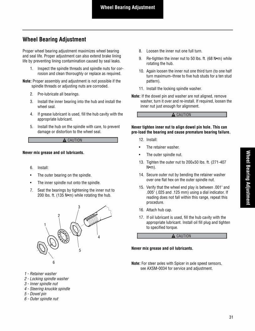
eneral Information
Warnings and Cautions
The description and specifications contained in this service publication are current at the time of printing.
Dana reserves the right to discontinue or modify its models and/or procedures and to change specifications at any timewithout notice.
Important Notice
Any reference to brand name in this publication is made as an example of the types of tools and materials recommended for use and should not be considered an endorsement. Equiva-lents may be used.
Always use genuine Spicer replacement parts.
Welding or machining on any axle component is prohibited unless noted otherwise in this document or other Spicer service literature.
Every effort has been made to ensure the accuracy of all information in this guide. However, Dana makes no expressed or implied warranty or representation based on the enclosed information.
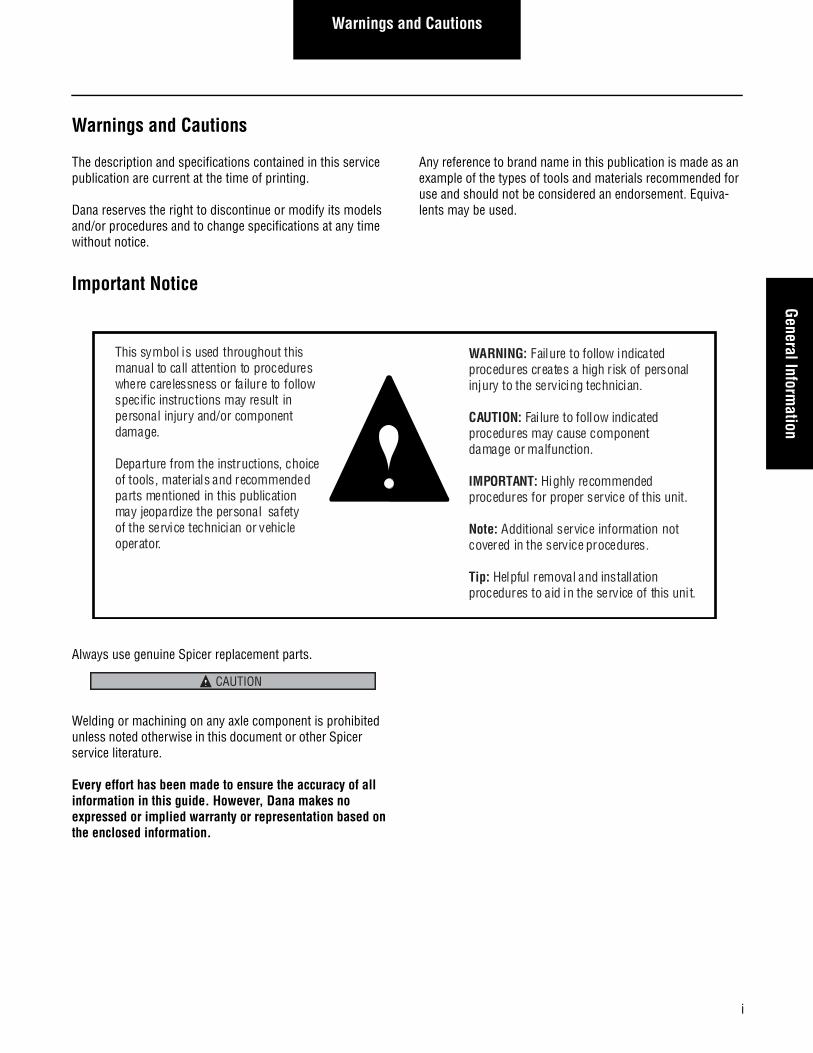
This symbol is used throughout this manual to call attention to procedures where carelessness or failure to follow specific instructions may result in personal injury and/or component damage.
Departure from the instructions, choice of tools, materials and recommended parts mentioned in this publication may jeopardize the personal safety of the service technician or vehicle operator.
WARNING: Failure to follow indicated procedures creates a high risk of personal injury to the servicing technician.
CAUTION: Failure to follow indicated procedures may cause component damage or malfunction.
IMPORTANT: Highly recommended procedures for proper service of this unit.
Note: Additional service information not covered in the service procedures.
Tip: Helpful removal and installation procedures to aid in the service of this unit.
CAUTION

ii
Warnings and Cautions
Table of ContentsTable of Contents
Warnings and Cautions ........................................ iImportant Notice .......................................................... iAxle Identification........................................................ 1Axle Assembly Tag ...................................................... 1Model Information ...................................................... 2Model Coverage .......................................................... 3
Inspection ...........................................................4Procedures and Intervals ............................................ 4E Family Exploded View .............................................. 4EFA Family Exploded View .......................................... 5I and D Family Exploded View ..................................... 6General Inspection ...................................................... 7Component Inspection ................................................ 7Knuckle Vertical Play Inspection ................................. 7Bushing Inspection (End Play) .................................... 8Tie Rod Inspection ...................................................... 9
................................ Tie Rod End Replacement 11Straight Socket Tie Rod Ends.................................... 11Drop Socket Tie Rod Ends ........................................ 11
Alignment / Adjustment ....................................12Wheel Alignment ....................................................... 12Camber ..................................................................... 12Caster Adjustment..................................................... 16Toe Setting................................................................ 17Steering Stop Adjustment ......................................... 18
Disassembly, Overhaul, and Assembly .............19
Steering Knuckle Disassembly................................... 19Kingpin Bushing and Seal Replacement .................... 20Steering Knuckle Assembly ....................................... 23Replacing Staked Draw Keys with Threaded.............. 26Installing Dual Draw Keys.......................................... 27
General Specifications ......................................28Wheel Bearing Adjustment ........................................ 28Wheel Alignment ....................................................... 28Kingpin Clearance – New ........................................... 28Kingpin Clearance – In Service .................................. 28E Family Fastener Torque Specifications.................... 29EFA Family Fastener Torque Specifications................ 29I and D Family Fastener Torque Specifications .......... 30
Wheel Bearing Adjustment ................................31Stamped Locking Nut System ................................... 32Single Nut (Castle Nut) Locking System.................... 33Pro-Torq Spindle Nut Service .................................... 34
Special Service Tools ........................................36Additional Service Information ..........................37Appendix ...........................................................38
Lubrication ................................................................ 38Verify Wheel End-play Procedure .............................. 40Readjust Wheel End-play Procedure.......................... 40

Table of Contents
1
General InformationG
eneral Information
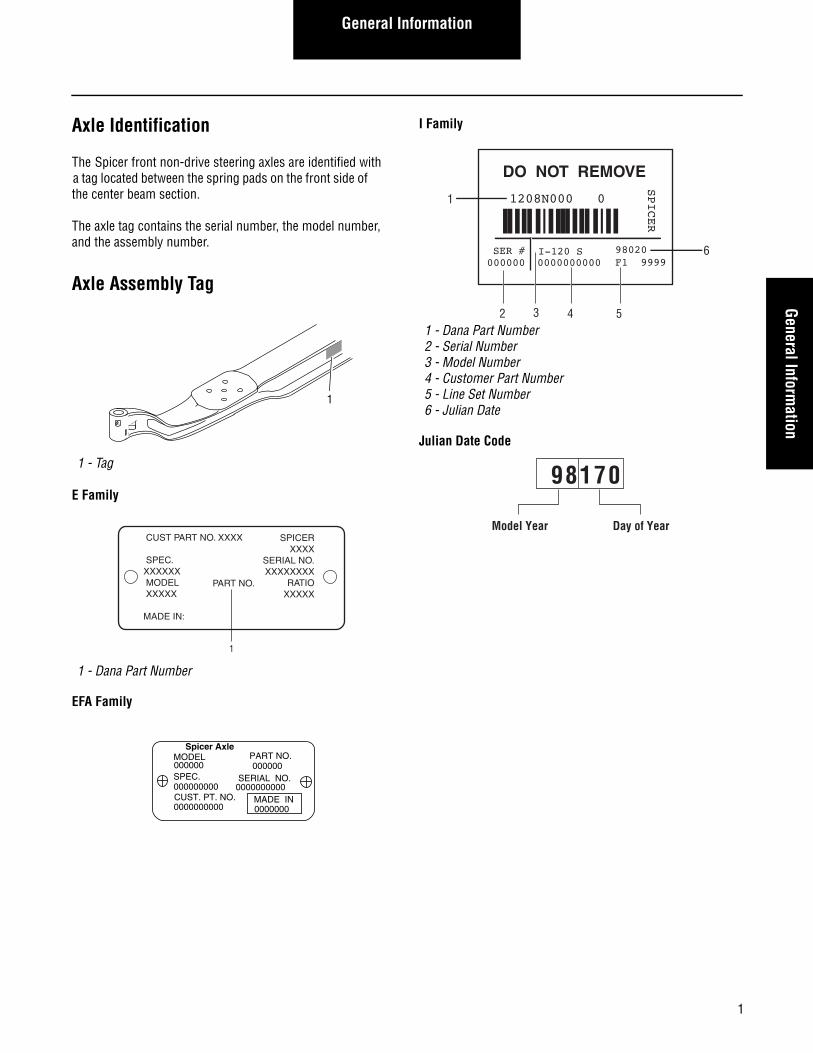
Axle Identification
The Spicer front non-drive steering axles are identified with a tag located between the spring pads on the front side of the center beam section.
The axle tag contains the serial number, the model number, and the assembly number.
Axle Assembly Tag
E Family
EFA Family
I Family
Julian Date Code
1 - Tag
1 - Dana Part Number
1
CUST PART NO. XXXX
SPEC.XXXXXX MODEL XXXXX
MADE IN:
PART NO.
SPICERXXXX
SERIAL NO.XXXXXXXX
RATIO XXXXX
1
Spicer AxleMODEL000000 000000
PART NO.
SPEC. SERIAL NO.000000000 0000000000CUST. PT. NO.0000000000
MADE IN0000000
1 - Dana Part Number2 - Serial Number3 - Model Number4 - Customer Part Number5 - Line Set Number6 - Julian Date
DO NOT REMOVE
1208N000 0
SPICER
SER # I-120 S000000 0000000000
98020F1 9999
1
2 3 4 5
6
98170
Model Year Day of Year
2
General Information
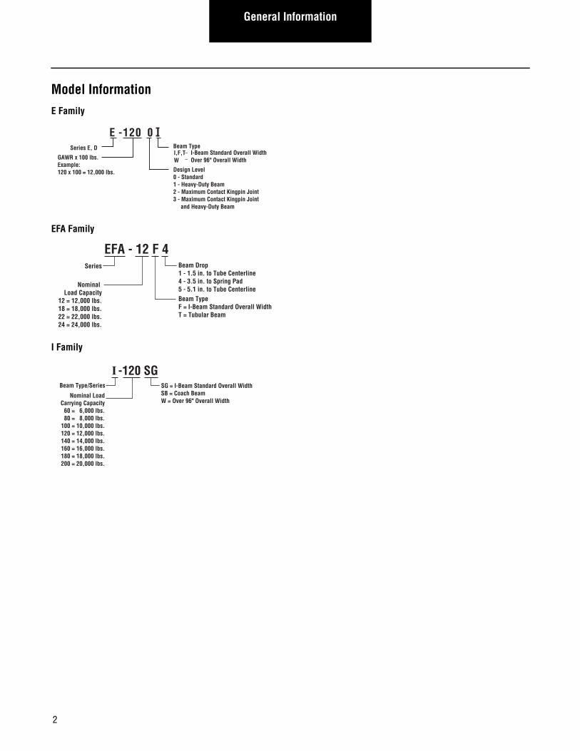
Model InformationE Family
EFA Family
I Family
Design Level0 - Standard1 - Heavy-Duty Beam2 - Maximum Contact Kingpin Joint3 - Maximum Contact Kingpin Joint and Heavy-Duty Beam
E -120 0 I
I,F,TW
––
I-Beam Standard Overall WidthOver 96" Overall Width
Beam TypeSeries E, D
GAWR x 100 lbs.Example: 120 x 100 = 12,000 lbs.
EFA - 12 F 4
Nominal Load Capacity
12 = 12,000 lbs.18 = 18,000 lbs.22 = 22,000 lbs.24 = 24,000 lbs.
Series
Beam TypeF = I-Beam Standard Overall WidthT = Tubular Beam
Beam Drop1 - 1.5 in. to Tube Centerline4 - 3.5 in. to Spring Pad5 - 5.1 in. to Tube Centerline
I -120 SG
Nominal Load Carrying Capacity
60 = 6,000 lbs. 80 = 8,000 lbs.100 = 10,000 lbs.120 = 12,000 lbs.140 = 14,000 lbs.160 = 16,000 lbs.180 = 18,000 lbs.200 = 20,000 lbs.
Beam Type/Series SG = I-Beam Standard Overall Width SB = Coach Beam W = Over 96" Overall Width
3
General InformationG
eneral Information
Model Coverage
E Family
EFA Family
I and D Family
Note: These nominal ratings are general guidelines. Actual load rating varies with application and duty cycle. Appli-cations require Spicer engineering approval.
Model Nominal Load Ratings lbs. [kg]
E-1000I E-1000W E-1002I E-1002W
10,000 [4,536]
E-1200I E-1200W E-1201W E-1202I E-1202WE-1203I
12,000 [5,443]
E-1320I E-1320W E-1322I E-1322W
13,200 [5,987]
E-1460I E-1460W E-1462I E-1462W
14,600 [6,622]
Model Nominal Load Rating lbs. [kg]
EFA-12F3 Superseded by EFA-12F4
EFA-13F3 Superseded by EFA-12F4
EFA-12F4 EFA-13F5
12,000-13,200[5,443-5,987]
EFA-18F3 Superseded by EFA-20F4
EFA-20F4 20,000 [9,072]
EFA-22T2 EFA-22T5
22,000 [9,979]
EFA-24T2 EFA-24T5
24,000 [10,886]
Model Nominal Load Rating lbs. [kg]
I-60SGD-600N
6,000 [2,722]
D-700ND-700F
7,000 [3,175]
D-800F D-800WI-80SG
8,000 [3,629]
D-850F D-850W
8,500 [3,856]
I-100 S, SG I-100W
10,000 [4,536]
I-120S, SG, SGL I-120W
12,000 [5,443]
I-130SG I-130W
13,000 [5,896]
I-132SG 13,200 [5,987]
I-140S, SG I-140W
14,600 [6,622]
I-160S, SG I-160W I-160SB
16,000 [7,257]
I-180S, SG I-180W
18,000 [8,165]
D-2000F 20,000 [9,072]
I-200S, SG I-200W
20,000 [9,072]
D-2200F 22,800 [10,342]
I-220W 22,800 [10,342]
4
Inspection
Inspection
Procedures and Intervals
The following inspection procedures are consistent with industry practice and are recommended as Inspection guide-lines for periodic service. Use manufacturer’s instructions as a primary guide.
E Family Exploded View
Intervals of inspection or service are recommended for gen-eral or average vehicle use. It may be appropriate to increase frequency of intervals depending on the type of vehicle ser-vice.
1 - Nut, Draw Key 10 - Pin, Cotter 19 - Gasket
2 - Seal, Grease 11 - Bolt, Clamp 20 - Bushing
3 - Shim 12 - Tube, Cross 21 - Kingpin
4 - Axle Beam 13 - Clamp 22 - Nut, outer Spindle*
5 - Key, Draw 14 - Nut 23 - Washer, Retainer*
6 - Bearing, Thrust 15 - Tie Rod End 24 - Washer, Spindle*
7 - Screw, Stop 16 - Lube Fitting 25 - Nut, Inner Spindle*
8 - Nut, Jam 17 - Cap, Knuckle 26 - Steering Knuckle
9 - Nut, Slotted 18 - Foam Insert 27 - Dual Draw Key Beam
* Nut, Pro-Torq (optional alternative for items 22-25)
6
2
3
4
26
19
16
21
1
7
8
16
19
17
20
17
20
2
25
24
22
1514
13
12
9
10
11
5
23
18
18
27
5
InspectionInspection
EFA Family Exploded View
1 - Lubrication Fitting 11 - Cotter Pin 21 - Woodruff Key
2 - Hex Bolt 12 - Hex Nut, Steer Arm 22 - Cross Tube Assembly
3 - Washer 13 - Seal Knuckle 23 - Tie Rod Arm
4 - Knuckle Cap 14 - Shim 24 - Steer Arm Ball Stud
5 - Bushing 15 - Thrust Bearing 25 - Ball Stud Nut
6 - Knuckle Pin 16 - Draw Key 26 - Ball Stud Cotter Pin
7 - Washer, Spindle 17 - Nut, Draw Key 27 - Steer Arm
8 - Hex Nut, Spindle 18 - Stop Screw 28 - I-Beam
9 - Cotter Pin 19 - Nut, Jam 29 - Tubular Beam
10 - Steering Knuckle 20 - Cotter Pin
1
27
2
4
11
12
2114
13
25
26
24
17
18
1915
13
16
20
216
23
10
7
8
9
3
5
22
29
28
6
Inspection
I and D Family Exploded View
1 - I-Beam 13 - Bushing, Kingpin 25 - Nut, Tie Rod Clamp
2 - Seal, Kingpin 14 - Kingpin 26 - Clamp, Tie Rod
3 - Shim 15 - Pin, Cotter 27 - Tie Rod End
4 - Draw Key, Outer 16 - Nut, Slotted 28 - Grease Fitting
5 - Draw Key, Inner 17 - Knuckle, Steering 29 - Arm, Tie Rod
6 - Nut, Draw Key 18 - Bolt, Stop 30 - Pin, Spindle Cotter
7 - Washer, Belleville 19 - Key, Woodruff 31 - Spindle Nut, Inner
8 - Bearing Assembly, Thrust 20 - Arm, Steering 32 - Nut, Spindle Lock Washer
9 - Bolt, Kingpin Cap 21 - Nut, Tie Rod 33 - Spindle Nut, Outer
10 - Grease Fitting 22 - Pin, Cotter Tie Rod 34 - Washer, Bearing Retainer
11 - Cap, Kingpin 23 - Tube, Cross 35 - Nut, Slotted Spindle
12 - O-Ring 24 - Bolt, Tie Rod Clamp
15
16
30
9
11
13
3
2
10
12
14
17
75
1
6
8
23
25
2624
27
28
22
21
29
19
2019
18
10
33 3231
4
3534
7
InspectionInspection
General Inspection
Inspect the axle to ensure proper assembly and to identify broken parts and loose fasteners each time the vehicle is lubricated. Make sure spring to axle beam mounting nuts and steering connection fasteners are secure.
Wheel Alignment - Follow vehicle manufacturer’s instructions for wheel alignment inspection intervals. If excessive steering effort, vehicle wander, or uneven and/or excessive tire wear is evident, check wheel alignment. Refer to Wheel Alignment.
Steering Axle Stops - Inspect for missing, loose or bent steer stops. Damaged or missing steering axle stops may indicate other problems with the steering system. This can result in damage to steering system components. Replace missing or damaged stops and reset steering system geometry. Refer to vehicle manufacturer’s instructions for proper steering sys-tem settings.
Tie Rod Ends - Inspect each time axle is lubricated. Check for seal damage, worn ball socket or loose fasteners.
Knuckle Thrust Bearings - When disassembled, visually inspect for any damage and check for smooth operation. For maximum service life, replace the thrust bearing whenever the knuckle assembly is serviced.
Kingpins - For maximum service life replace kingpins when servicing knuckle assembly.
Component Inspection
Prepare for axle inspection as follows:
1. Set parking brake and block drive wheels to prevent vehicle movement.
2. Raise the vehicle until steering axle wheels are off the ground. Support raised vehicle with safety stands.
Never work under a vehicle supported only by a jack. Always use safety stands.
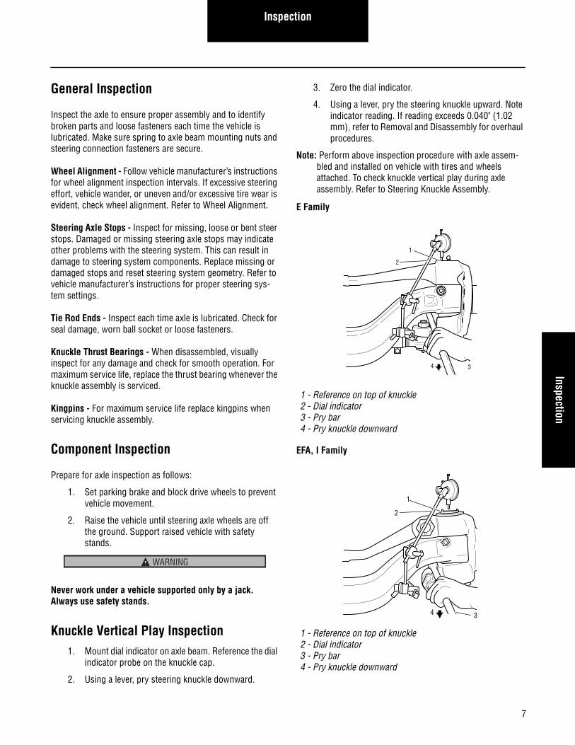
Knuckle Vertical Play Inspection1. Mount dial indicator on axle beam. Reference the dial
indicator probe on the knuckle cap.
2. Using a lever, pry steering knuckle downward.
3. Zero the dial indicator.
4. Using a lever, pry the steering knuckle upward. Note indicator reading. If reading exceeds 0.040" (1.02 mm), refer to Removal and Disassembly for overhaul procedures.
Note: Perform above inspection procedure with axle assem-bled and installed on vehicle with tires and wheels attached. To check knuckle vertical play during axle assembly. Refer to Steering Knuckle Assembly.
E Family
EFA, I Family
WARNING
1 - Reference on top of knuckle2 - Dial indicator3 - Pry bar4 - Pry knuckle downward
1 - Reference on top of knuckle2 - Dial indicator3 - Pry bar4 - Pry knuckle downward
2
1
34
1
2
34
8
Inspection
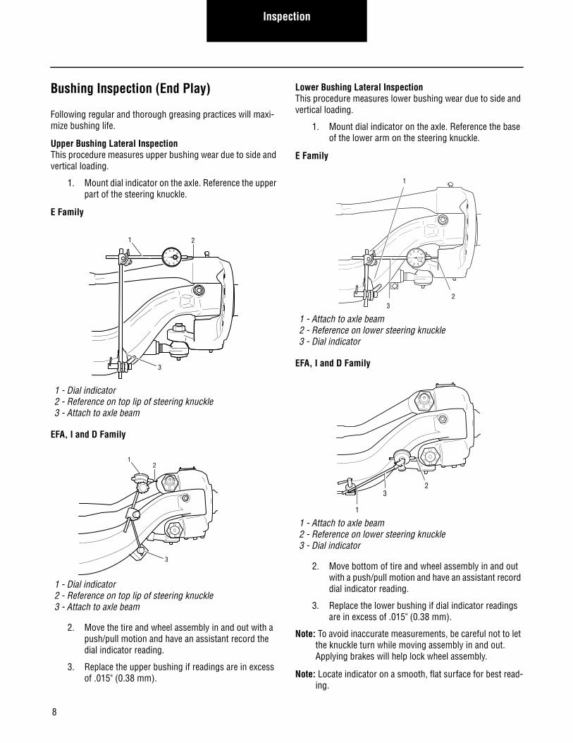
Bushing Inspection (End Play)
Following regular and thorough greasing practices will maxi-mize bushing life.
Upper Bushing Lateral InspectionThis procedure measures upper bushing wear due to side and vertical loading.
1. Mount dial indicator on the axle. Reference the upper part of the steering knuckle.
E Family
EFA, I and D Family
2. Move the tire and wheel assembly in and out with a push/pull motion and have an assistant record the dial indicator reading.
3. Replace the upper bushing if readings are in excess of .015" (0.38 mm).
Lower Bushing Lateral InspectionThis procedure measures lower bushing wear due to side and vertical loading.
1. Mount dial indicator on the axle. Reference the base of the lower arm on the steering knuckle.
E Family
EFA, I and D Family
2. Move bottom of tire and wheel assembly in and out with a push/pull motion and have an assistant record dial indicator reading.
3. Replace the lower bushing if dial indicator readings are in excess of .015" (0.38 mm).
Note: To avoid inaccurate measurements, be careful not to let the knuckle turn while moving assembly in and out. Applying brakes will help lock wheel assembly.
Note: Locate indicator on a smooth, flat surface for best read-ing.
1 - Dial indicator2 - Reference on top lip of steering knuckle3 - Attach to axle beam
1 - Dial indicator2 - Reference on top lip of steering knuckle3 - Attach to axle beam
010
20 30
4050
40
302010
21
3
21
3
1 - Attach to axle beam2 - Reference on lower steering knuckle3 - Dial indicator
1 - Attach to axle beam2 - Reference on lower steering knuckle3 - Dial indicator
010
20 30
4050
40
3020
10
32
1
32
1
9
InspectionInspection
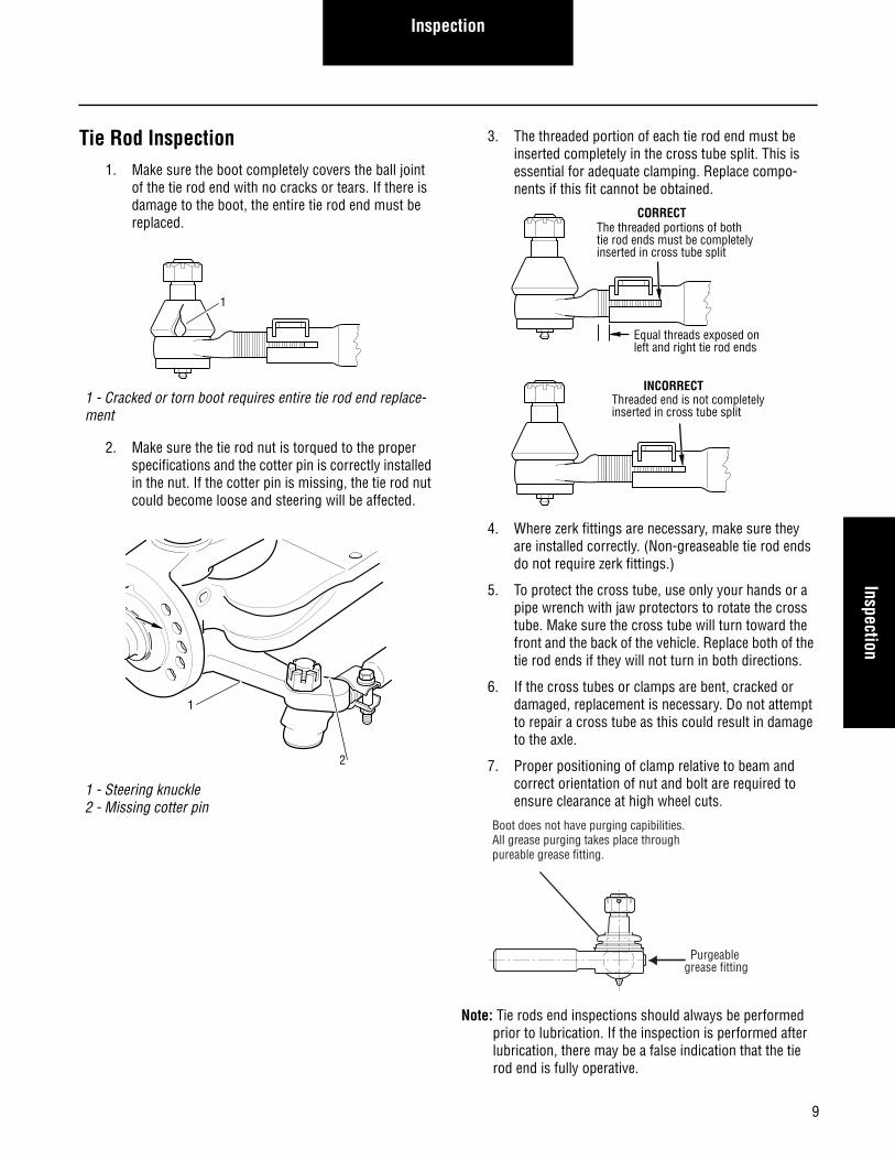
Tie Rod Inspection1. Make sure the boot completely covers the ball joint
of the tie rod end with no cracks or tears. If there is damage to the boot, the entire tie rod end must be replaced.
2. Make sure the tie rod nut is torqued to the proper specifications and the cotter pin is correctly installed in the nut. If the cotter pin is missing, the tie rod nut could become loose and steering will be affected.
3. The threaded portion of each tie rod end must be inserted completely in the cross tube split. This is essential for adequate clamping. Replace compo-nents if this fit cannot be obtained.
4. Where zerk fittings are necessary, make sure they are installed correctly. (Non-greaseable tie rod ends do not require zerk fittings.)
5. To protect the cross tube, use only your hands or a pipe wrench with jaw protectors to rotate the cross tube. Make sure the cross tube will turn toward the front and the back of the vehicle. Replace both of the tie rod ends if they will not turn in both directions.
6. If the cross tubes or clamps are bent, cracked or damaged, replacement is necessary. Do not attempt to repair a cross tube as this could result in damage to the axle.
7. Proper positioning of clamp relative to beam and correct orientation of nut and bolt are required to ensure clearance at high wheel cuts.
Note: Tie rods end inspections should always be performed prior to lubrication. If the inspection is performed after lubrication, there may be a false indication that the tie rod end is fully operative.
1 - Cracked or torn boot requires entire tie rod end replace-ment
1 - Steering knuckle2 - Missing cotter pin
1
1
2
The threaded portions of both tie rod ends must be completely inserted in cross tube split
Threaded end is not completelyinserted in cross tube split
CORRECT
INCORRECT
Equal threads exposed onleft and right tie rod ends
Boot does not have purging capibilities.All grease purging takes place throughpureable grease fitting.
Purgeable grease fitting
10
Inspection
8. Park the vehicle with the wheels in the “straight ahead” position, then turn the vehicle off.
9. Place blocks in front of and behind the front and rear tires to prevent the vehicle from moving.
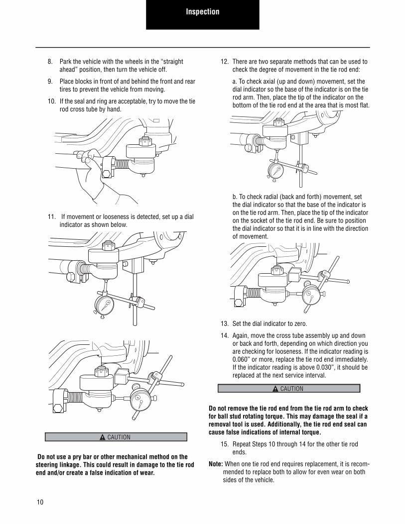
10. If the seal and ring are acceptable, try to move the tie rod cross tube by hand.
11. If movement or looseness is detected, set up a dial indicator as shown below.
Do not use a pry bar or other mechanical method on the steering linkage. This could result in damage to the tie rod end and/or create a false indication of wear.
12. There are two separate methods that can be used to check the degree of movement in the tie rod end:
a. To check axial (up and down) movement, set the dial indicator so the base of the indicator is on the tie rod arm. Then, place the tip of the indicator on the bottom of the tie rod end at the area that is most flat.
b. To check radial (back and forth) movement, set the dial indicator so that the base of the indicator is on the tie rod arm. Then, place the tip of the indicator on the socket of the tie rod end. Be sure to position the dial indicator so that it is in line with the direction of movement.
13. Set the dial indicator to zero.
14. Again, move the cross tube assembly up and down or back and forth, depending on which direction you are checking for looseness. If the indicator reading is 0.060” or more, replace the tie rod end immediately. If the indicator reading is above 0.030”, it should be replaced at the next service interval.
Do not remove the tie rod end from the tie rod arm to check for ball stud rotating torque. This may damage the seal if a removal tool is used. Additionally, the tie rod end seal can cause false indications of internal torque.
15. Repeat Steps 10 through 14 for the other tie rod ends.
Note: When one tie rod end requires replacement, it is recom-mended to replace both to allow for even wear on both sides of the vehicle.
CAUTION
CAUTION
11
Tie Rod End ReplacementTie Rod End Replacem
ent
Tie Rod End Replacement1. Disconnect the tie rod end.
2. If the cross tube is being replaced, count the number of exposed threads on the tie rod end.
3. Loosen the clamp nut and unscrew the tie rod end.
4. Install new tie rod ends or new cross tube.
Note: Cross tube has right-hand and left-hand threads for corresponding sides of the vehicle.
5. Thread tie rod end into cross tube past the tube split. The number of threads exposed from the tube should be equal on both left and right tie rod ends.
6. For E and I straight socket tie rod ends, tighten the clamp nut to 45-60 ft. lbs. (61-81N m). Make sure the tab on the clamp holds the end of the cross tube.
Straight Socket Tie Rod Ends
7. For drop socket tie rod ends, tighten as follows:
Drop Socket Tie Rod Ends
8. Install tie rod end into knuckle tie rod arm. Secure with slotted nut and tighten to 120-160 ft. lbs. (163-217 N m).
9. Install the cotter pin in the slotted nut and bend the ends to secure. If necessary, tighten the nut until the holes align.
10. Adjust toe-in.
Note: On tie rods with rotating clamp, position clamp with fastener away from beam.
D, E, & I Series 45-60 ft.lbs. (61-81 N•m)
The threaded portions of both tie rod ends must be completely inserted in cross tube split
Threaded end is not completelyinserted in cross tube split
CORRECT
INCORRECT
Equal threads exposed onleft and right tie rod ends
I-120SG, I-140SG, I-132SG, E-1462I
55-70 ft. lbs.(75-95 N•m)
E-1460I, E-1320W, E-1322W E-1460W, E-1462W
80-90 ft. lbs.(108-122 N•m)
I-200SG, I-200W, I-220W, I-160W, I-180W
150-180 ft. lbs.(203-244 N•m)
D-2000F, D2200F 150-180 ft. lbs.(203-244 N•m)
1 - Tie rod arm2 - Tie rod end3 - Slotted nut4 - Cotter pin5 - Position clamp fastener away from beam
1
4
3
25
12
Alignment / Adjustment
Alignment / Adjustment
Wheel Alignment
Correct wheel alignment promotes longer tire wear and ease of handling while minimizing strain on the steering system and axle components. Use vehicle manufacturer’s instructions to inspect wheel alignment.Note: Total vehicle alignment is recommended when aligning
the steer axle.
Camber
Camber is the vertical tilt of the wheel as viewed from the front of the vehicle. This is machined in at time of manufac-ture and is not adjustable.
“Positive” camber is an outward tilt of the wheel at the top.
Camber for E-1000I, E-1000W, E-1200I, E-1200W, E-1201W, E-1320I, E-1320W, E-1460I, E-1460W
“Negative” camber is an inward tilt of the wheel at the top.
Spicer expressly prohibits bending of axle beams (hot or cold) to change camber or for any other purpose. Weld-ing or machining on any axle component is prohibited unless noted otherwise in this document or other Spicer service literature.
1 - Positive camber2 - Vertical center line
21
1 - Vertical center line2 - Negative camber
21
CAUTION
On Bench Unloaded(8000 lbs.)
Loaded
)°61/7-/+( °0)°61/7-/+( °61/3)°61/7-/+( °2/1tfeL
)°61/7-/+( °4/1-)°61/7-/+( °61/1-)°61/7-/+( °4/1thgiR
13
Alignment / AdjustmentAlignm
ent / Adjustment
Camber for E-1002I, E-1002W, E-1202I, E-1202W, E-1203I E-1322I, E-1322W, E-1462I, E-1462W
Camber for EFA-12F3, EFA-12F4, EFA-13F3, EFA-13F5
Camber for EFA-18F3, EFA-20F4
Camber for EFA-22T, EFA-24T
Camber for I-60SG, I-80SG
On Bench Unloaded(8000 lbs.)
Loaded
Left 5/8° (+/-7/16°) 1/4° (+/-7/16°) +1/8° (+/-7/16°)
Right 3/8° (+/-7/16°) 0° (+/-7/16°) -1/8° (+/-7/16°)
On Bench Unloaded(8000 lbs.)
Loaded
Left 3/4° (+/-7/16°) 7/16° (+/-7/16°) 1/4° (+/-7/16°)
Right 1/4° (+/-7/16°) -1/16° (+/-7/16°) -1/4° (+/-7/16°)
On Bench Unloaded(10,000 lbs.)
Loaded
Left 3/4° (+/-7/16°) 1/2° (+/-7/16°) 1/4° (+/-7/16°)
Right 1/4° (+/-7/16°) 0° (+/-7/16°) -1/4° (+/-7/16°)
On Bench Unloaded(12,000 lbs.)
Loaded
Left 1/2° (+/-7/16°) 1/4° (+/-7/16°) 0° (+/-7/16°)
Right 1/2° (+/-7/16°) 1/4° (+/-7/16°) 0° (+/-7/16°)
On Bench Unloaded(8,000 lbs.)
Loaded
Left 3/4° (+/-7/16°) 3/8° (+/-7/16°) 1/4° (+/-7/16°)
Right 1/2° (+/-7/16°) 1/8° (+/-7/16°) 0° (+/-7/16°)
14
Alignment / Adjustment
Camber for D-600N, D-700F, D-700N, D-800F, D-800W
Camber for I-100SG, I-120SG, I-130SG, I-132SG, I-140SG, I-146SG, I-160SG, I-180SG, I-200SG prior to Oct. 2001
Camber for I-100SG, I-120SG, I-140SG, I-146SG, I-160SG, I-180SG, I-200SG after Oct. 2001
Camber for I-100NGV, I-120NGV, I-140NGV prior to Oct. 2001
Camber for I-100NGV, I-120NGV, I-140NGV after Oct. 2001
On Bench Unloaded(8,000 lbs.)
Loaded
Left 5/8° (+/-7/16°) 1/4° (+/-7/16°) +1/8° (+/-7/16°)
Right 3/8° (+/-7/16°) 0° (+/-7/16°) -1/8° (+/-7/16°)
On Bench Unloaded(8,000 lbs.)
Loaded
Left 1/4° (+/-7/16°) -1/8° (+/-7/16°) -1/4° (+/-7/16°)
Right 1/4° (+/-7/16°) -1/8° (+/-7/16°) -1/4° (+/-7/16°)
On Bench Unloaded(8,000 lbs.)
Loaded
Left 5/8° (+/-7/16°) 1/4° (+/-7/16°) +1/8° (+/-7/16°)
Right 3/8° (+/-7/16°) 0° (+/-7/16°) -1/8° (+/-7/16°)
On Bench Unloaded Loaded
Left 1/4° (+/-7/16°) -1/8° (+/-7/16°) -1/4° (+/-7/16°)
Right 1/4° (+/-7/16°) -1/8° (+/-7/16°) -1/4° (+/-7/16°)
On Bench Unloaded Loaded
Left 5/8° (+/-7/16°) 1/4° (+/-7/16°) +1/8° (+/-7/16°)
Right 3/8° (+/-7/16°) 0° (+/-7/16°) -1/8° (+/-7/16°)
15
Alignment / AdjustmentAlignm
ent / Adjustment
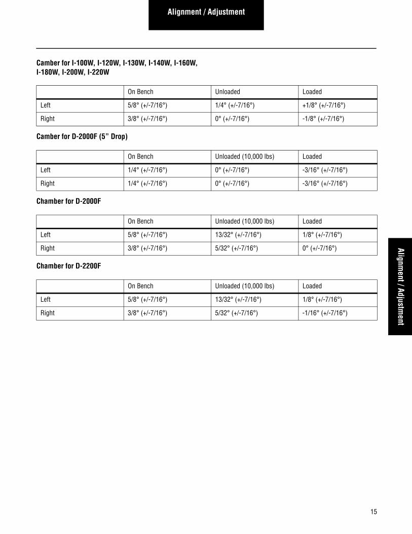
Camber for I-100W, I-120W, I-130W, I-140W, I-160W, I-180W, I-200W, I-220W
Camber for D-2000F (5” Drop)
Chamber for D-2000F
Chamber for D-2200F
On Bench Unloaded Loaded
Left 5/8° (+/-7/16°) 1/4° (+/-7/16°) +1/8° (+/-7/16°)
Right 3/8° (+/-7/16°) 0° (+/-7/16°) -1/8° (+/-7/16°)
On Bench Unloaded (10,000 lbs) Loaded
Left 1/4° (+/-7/16°) 0° (+/-7/16°) -3/16° (+/-7/16°)
Right 1/4° (+/-7/16°) 0° (+/-7/16°) -3/16° (+/-7/16°)
On Bench Unloaded (10,000 lbs) Loaded
Left 5/8° (+/-7/16°) 13/32° (+/-7/16°) 1/8° (+/-7/16°)
Right 3/8° (+/-7/16°) 5/32° (+/-7/16°) 0° (+/-7/16°)
On Bench Unloaded (10,000 lbs) Loaded
Left 5/8° (+/-7/16°) 13/32° (+/-7/16°) 1/8° (+/-7/16°)
Right 3/8° (+/-7/16°) 5/32° (+/-7/16°) -1/16° (+/-7/16°)
16
Alignment / Adjustment
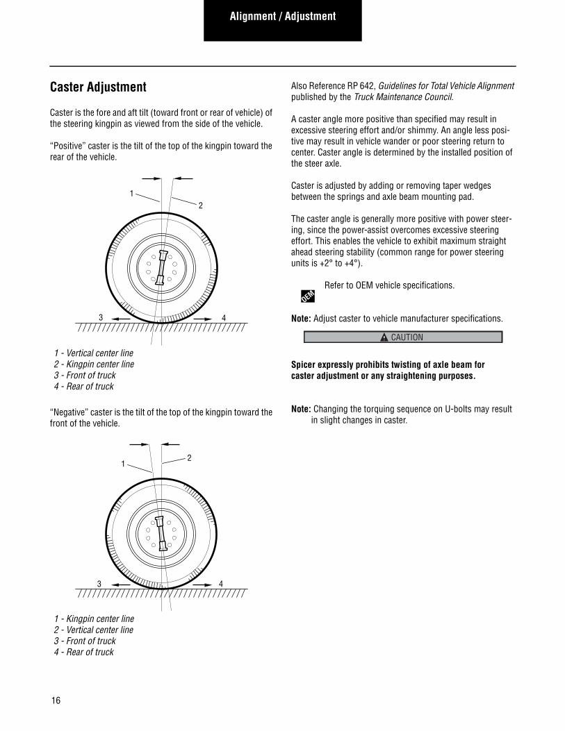
Caster Adjustment
Caster is the fore and aft tilt (toward front or rear of vehicle) of the steering kingpin as viewed from the side of the vehicle.
“Positive” caster is the tilt of the top of the kingpin toward the rear of the vehicle.
“Negative” caster is the tilt of the top of the kingpin toward the front of the vehicle.
Also Reference RP 642, Guidelines for Total Vehicle Alignment published by the Truck Maintenance Council.
A caster angle more positive than specified may result in excessive steering effort and/or shimmy. An angle less posi-tive may result in vehicle wander or poor steering return to center. Caster angle is determined by the installed position of the steer axle.
Caster is adjusted by adding or removing taper wedges between the springs and axle beam mounting pad.
The caster angle is generally more positive with power steer-ing, since the power-assist overcomes excessive steering effort. This enables the vehicle to exhibit maximum straight ahead steering stability (common range for power steering units is +2° to +4°).
Refer to OEM vehicle specifications.
Note: Adjust caster to vehicle manufacturer specifications.
Spicer expressly prohibits twisting of axle beam for caster adjustment or any straightening purposes.
Note: Changing the torquing sequence on U-bolts may result in slight changes in caster.
1 - Vertical center line2 - Kingpin center line3 - Front of truck4 - Rear of truck
1 - Kingpin center line2 - Vertical center line3 - Front of truck4 - Rear of truck
43
12
43
21
OEM
CAUTION
17
Alignment / AdjustmentAlignm
ent / Adjustment
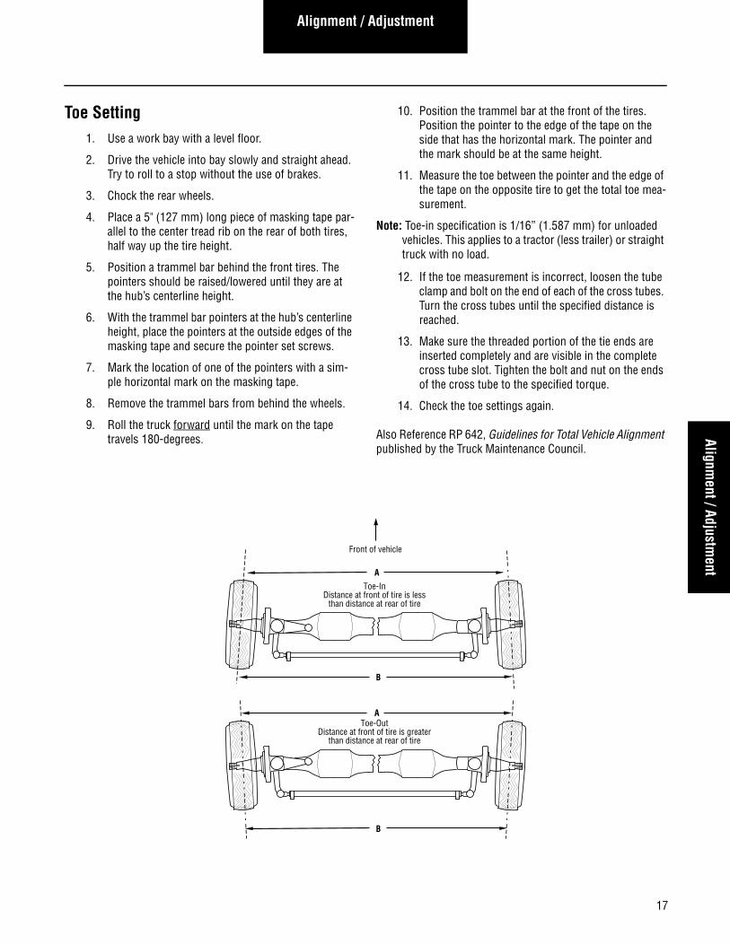
Toe Setting1. Use a work bay with a level floor.
2. Drive the vehicle into bay slowly and straight ahead. Try to roll to a stop without the use of brakes.
3. Chock the rear wheels.
4. Place a 5" (127 mm) long piece of masking tape par-allel to the center tread rib on the rear of both tires, half way up the tire height.
5. Position a trammel bar behind the front tires. The pointers should be raised/lowered until they are at the hub’s centerline height.
6. With the trammel bar pointers at the hub’s centerline height, place the pointers at the outside edges of the masking tape and secure the pointer set screws.
7. Mark the location of one of the pointers with a sim-ple horizontal mark on the masking tape.
8. Remove the trammel bars from behind the wheels.
9. Roll the truck forward until the mark on the tape travels 180-degrees.
10. Position the trammel bar at the front of the tires. Position the pointer to the edge of the tape on the side that has the horizontal mark. The pointer and the mark should be at the same height.
11. Measure the toe between the pointer and the edge of the tape on the opposite tire to get the total toe mea-surement.
Note: Toe-in specification is 1/16” (1.587 mm) for unloaded vehicles. This applies to a tractor (less trailer) or straight truck with no load.
12. If the toe measurement is incorrect, loosen the tube clamp and bolt on the end of each of the cross tubes. Turn the cross tubes until the specified distance is reached.
13. Make sure the threaded portion of the tie ends are inserted completely and are visible in the complete cross tube slot. Tighten the bolt and nut on the ends of the cross tube to the specified torque.
14. Check the toe settings again.
Also Reference RP 642, Guidelines for Total Vehicle Alignment published by the Truck Maintenance Council.
Front of vehicle
A
B
Toe-InDistance at front of tire is less
than distance at rear of tire
B
AToe-Out
Distance at front of tire is greaterthan distance at rear of tire
18
Alignment / Adjustment
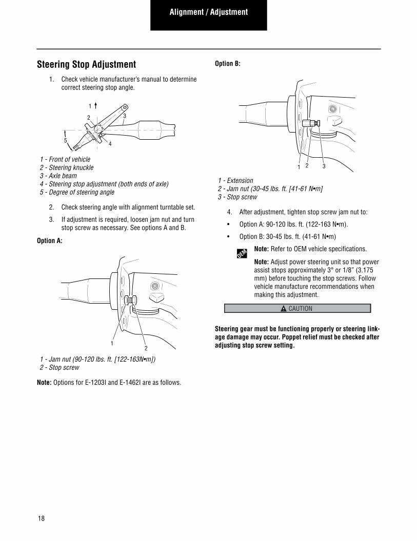
Steering Stop Adjustment1. Check vehicle manufacturer’s manual to determine
correct steering stop angle.
2. Check steering angle with alignment turntable set.
3. If adjustment is required, loosen jam nut and turn stop screw as necessary. See options A and B.
Option A:
Note: Options for E-1203I and E-1462I are as follows.
Option B:
4. After adjustment, tighten stop screw jam nut to:
• Option A: 90-120 lbs. ft. (122-163 N•m).
• Option B: 30-45 lbs. ft. (41-61 N•m)
Note: Refer to OEM vehicle specifications.
Note: Adjust power steering unit so that power assist stops approximately 3° or 1/8” (3.175 mm) before touching the stop screws. Follow vehicle manufacture recommendations when making this adjustment.
Steering gear must be functioning properly or steering link-age damage may occur. Poppet relief must be checked after adjusting stop screw setting.
1 - Front of vehicle2 - Steering knuckle3 - Axle beam4 - Steering stop adjustment (both ends of axle)5 - Degree of steering angle
1 - Jam nut (90-120 lbs. ft. [122-163N•m])2 - Stop screw
2
5
3
4
1
12
1 - Extension2 - Jam nut (30-45 lbs. ft. [41-61 N•m]3 - Stop screw
1 2 3
OEM
CAUTION
19
Disassembly, Overhaul, and Assembly
Disassembly, Overhaul,
and Assembly
Disassembly, Overhaul, and Assembly
Steering Knuckle DisassemblyPreparation
1. Set parking brake and block drive wheels to prevent vehicle movement.
2. Raise vehicle until steer axle tires are off the ground. Support raised vehicle with safety stands.
Never work under a vehicle supported by only a jack. Always use safety stands.
Procedure
1. Loosen the slack adjuster to return brake shoes to the released position and clear drum.
2. Remove hub cap, cotter pin, nut, washer, and outer bearing cone assembly.
3. Remove wheel and hub assembly.
4. Disconnect air or hydraulic line from the brake assembly.
Note: Plug or cap line to prevent brake system contamination.
5. Remove brake assembly.
6. Remove cotter pin and slotted nut.
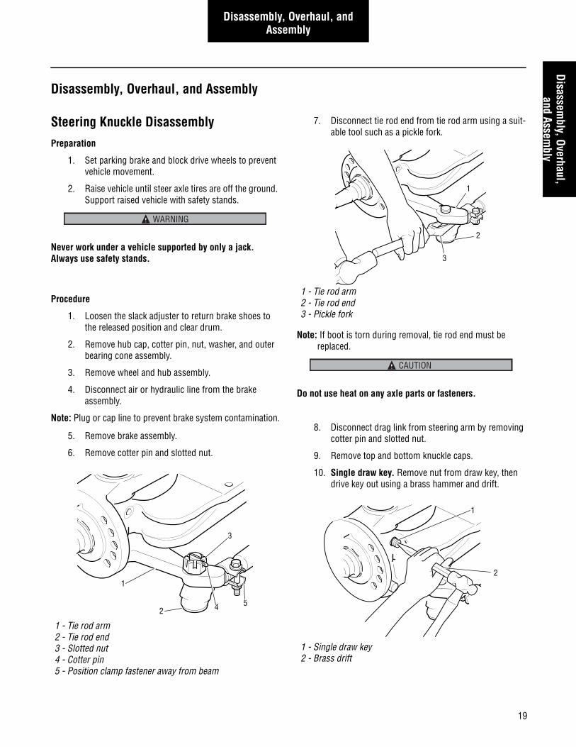
7. Disconnect tie rod end from tie rod arm using a suit-able tool such as a pickle fork.
Note: If boot is torn during removal, tie rod end must be replaced.
Do not use heat on any axle parts or fasteners.
8. Disconnect drag link from steering arm by removing cotter pin and slotted nut.
9. Remove top and bottom knuckle caps.
10. Single draw key. Remove nut from draw key, then drive key out using a brass hammer and drift.
1 - Tie rod arm2 - Tie rod end3 - Slotted nut4 - Cotter pin5 - Position clamp fastener away from beam
WARNING
1
4
3
25
1 - Tie rod arm2 - Tie rod end3 - Pickle fork
1 - Single draw key2 - Brass drift
3
2
1
CAUTION
1
2
20
Disassembly, Overhaul, and Assembly
11. Dual draw keys. Remove both draw key nuts. Then drive key out using a brass hammer and drift.
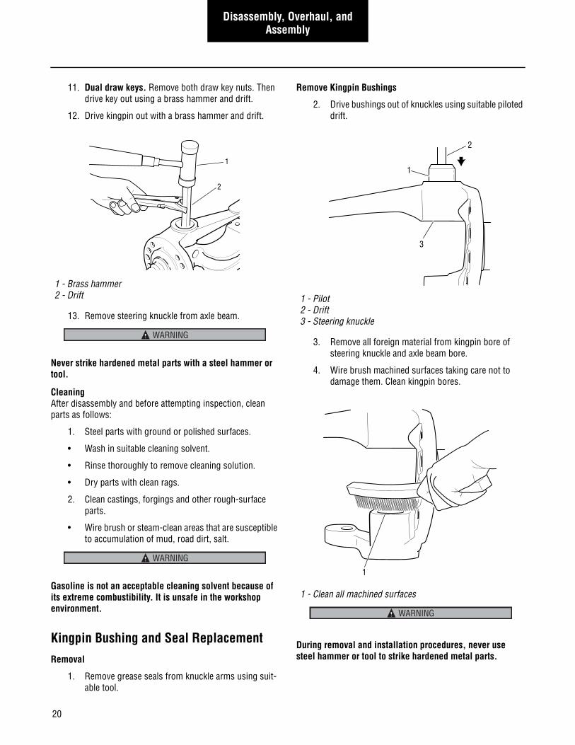
12. Drive kingpin out with a brass hammer and drift.
13. Remove steering knuckle from axle beam.
Never strike hardened metal parts with a steel hammer or tool.
CleaningAfter disassembly and before attempting inspection, clean parts as follows:
1. Steel parts with ground or polished surfaces.
• Wash in suitable cleaning solvent.
• Rinse thoroughly to remove cleaning solution.
• Dry parts with clean rags.
2. Clean castings, forgings and other rough-surface parts.
• Wire brush or steam-clean areas that are susceptible to accumulation of mud, road dirt, salt.
Gasoline is not an acceptable cleaning solvent because of its extreme combustibility. It is unsafe in the workshop environment.
Kingpin Bushing and Seal ReplacementRemoval
1. Remove grease seals from knuckle arms using suit-able tool.
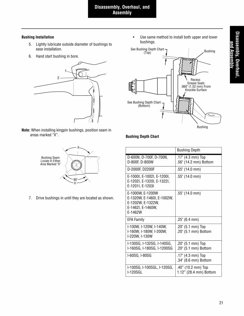
Remove Kingpin Bushings
2. Drive bushings out of knuckles using suitable piloted drift.
3. Remove all foreign material from kingpin bore of steering knuckle and axle beam bore.
4. Wire brush machined surfaces taking care not to damage them. Clean kingpin bores.
During removal and installation procedures, never use steel hammer or tool to strike hardened metal parts.
1 - Brass hammer2 - Drift
2
1
WARNING
WARNING
1 - Pilot2 - Drift3 - Steering knuckle
1 - Clean all machined surfaces
1
2
3
1
WARNING
21
Disassembly, Overhaul, and Assembly
Disassembly, Overhaul,
and Assembly
Bushing Installation
5. Lightly lubricate outside diameter of bushings to ease installation.
6. Hand start bushing in bore.
Note: When installing kingpin bushings, position seam in areas marked “X”.
7. Drive bushings in until they are located as shown.
• Use same method to install both upper and lower bushings.
Bushing Depth Chart
1
2
90˚
X
Bushing SeamLocate in EitherArea Marked "X"
X
Bushing Depth
D-600N, D-700F, D-700N, D-800F, D-800W
.17" (4.3 mm) Top
.56" (14.2 mm) Bottom
D-2000F, D2200F .55" (14.0 mm)
E-1000I, E-1002I, E-1200I, E-1202I, E-1320I, E-1322I, E-1201I, E-1203I
.55" (14.0 mm)
E-1000W, E-1200W E-1320W, E-1460I, E-1002W, E-1202W, E-1322W, E-1462I, E-1460W, E-1462W
.55" (14.0 mm)
EFA Family .25" (6.4 mm)
I-100W, I-120W, I-140W, I-160W, I-180W, I-200W, I-220W, I-130W
.20" (5.1 mm) Top
.20" (5.1 mm) Bottom
I-130SG, I-132SG, I-140SG, I-160SG, I-180SG, I-1200SG
.20" (5.1 mm) Top
.20" (5.1 mm) Bottom
I-60SG, I-80SG .17" (4.3 mm) Top.34" (8.6 mm) Bottom
I-100SG, I-100SGL, I-120SG, I-120SGL
.40” (10.2 mm) Top 1.12” (28.4 mm) Bottom
Recess Grease Seals
.060" (1.52 mm) FromKnuckle Surface
See Bushing Depth Chart(Bottom)
See Bushing Depth Chart(Top)
Bushing
Bushing
22
Disassembly, Overhaul, and Assembly
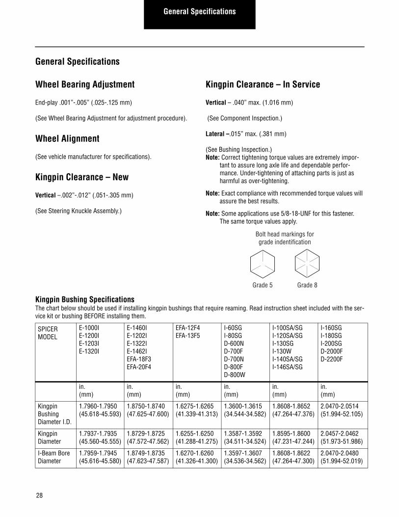
Note: Some Spicer kingpin bushings require reaming after installation. Read the instruction sheet included with the service kit or bushings BEFORE beginning installation. For dimensions of bushings requiring ream-ing, refer to the Kingpin Bushing Specifications chart shown in the Appendix.
8. Ream bushings to proper size using appropriate Kent-Moore tool (or equivalent).
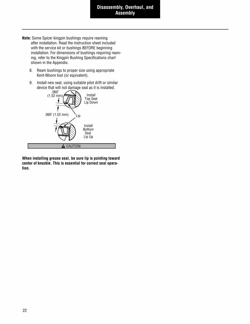
9. Install new seal, using suitable pilot drift or similar device that will not damage seal as it is installed.
When installing grease seal, be sure lip is pointing toward center of knuckle. This is essential for correct seal opera-tion.
InstallTop SealLip Down
InstallBottomSeal
Lip Up
Lip
.060"(1.52 mm)
.060" (1.52 mm)
CAUTION
23
Disassembly, Overhaul, and Assembly
Disassembly, Overhaul,
and Assembly
Steering Knuckle AssemblyNote: Always replace kingpin, thrust bearing and bushings if
any component is faulty.
1. Before installing the kingpins, lubricate inside of bushing and outside of kingpins with Fleetrite EP2 Moly Grease or equivalent NLGI No. 2 multipurpose lithium grease to provide initial lubrication.
2. Make certain that kingpin hole in axle center is clean and dry.
3. There may be two styles of thrust bearings. One type is installed on thrust bearing with seal on top, as show in the following figure. Position and support the steering knuckle assembly on the axle end.
4. The second style thrust bearing is a one piece design with seal LIP installed TOWARDS the bottom of the knuckles as show in the following figure.
5. Slide the thrust bearing between the lower face of axle center and lower steering knuckle yoke.
6. Align the steering knuckle yoke holes with axle and thrust bearing holes.
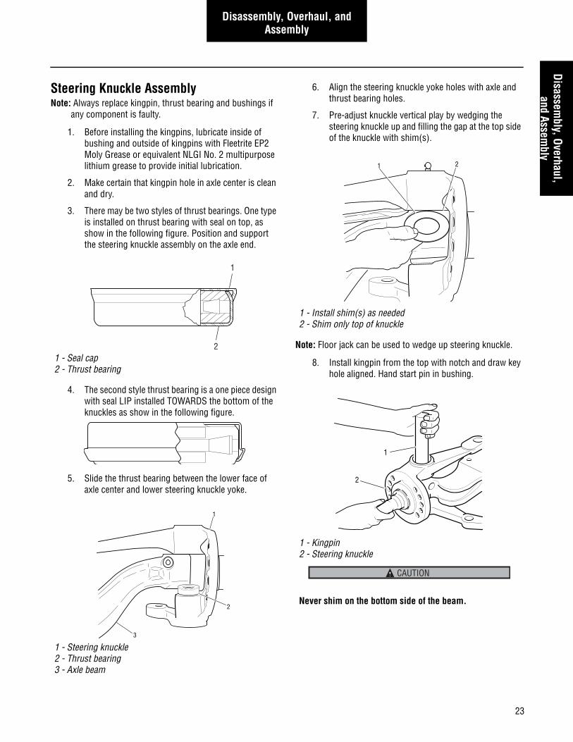
7. Pre-adjust knuckle vertical play by wedging the steering knuckle up and filling the gap at the top side of the knuckle with shim(s).
Note: Floor jack can be used to wedge up steering knuckle.
8. Install kingpin from the top with notch and draw key hole aligned. Hand start pin in bushing.
1 - Seal cap2 - Thrust bearing
1 - Steering knuckle2 - Thrust bearing3 - Axle beam
1
2
1
3
2
1 - Install shim(s) as needed2 - Shim only top of knuckle
1 - Kingpin2 - Steering knuckle
Never shim on the bottom side of the beam.
1 2
1
2
CAUTION
24
Disassembly, Overhaul, and Assembly
9. Install kingpin in knuckle and axle beam. Tap kingpin in place using hammer and brass drift if necessary.
Protect kingpins with a suitable material such as shim stock.
Note: At this point in reassembly, check knuckle vertical play and adjust if necessary.
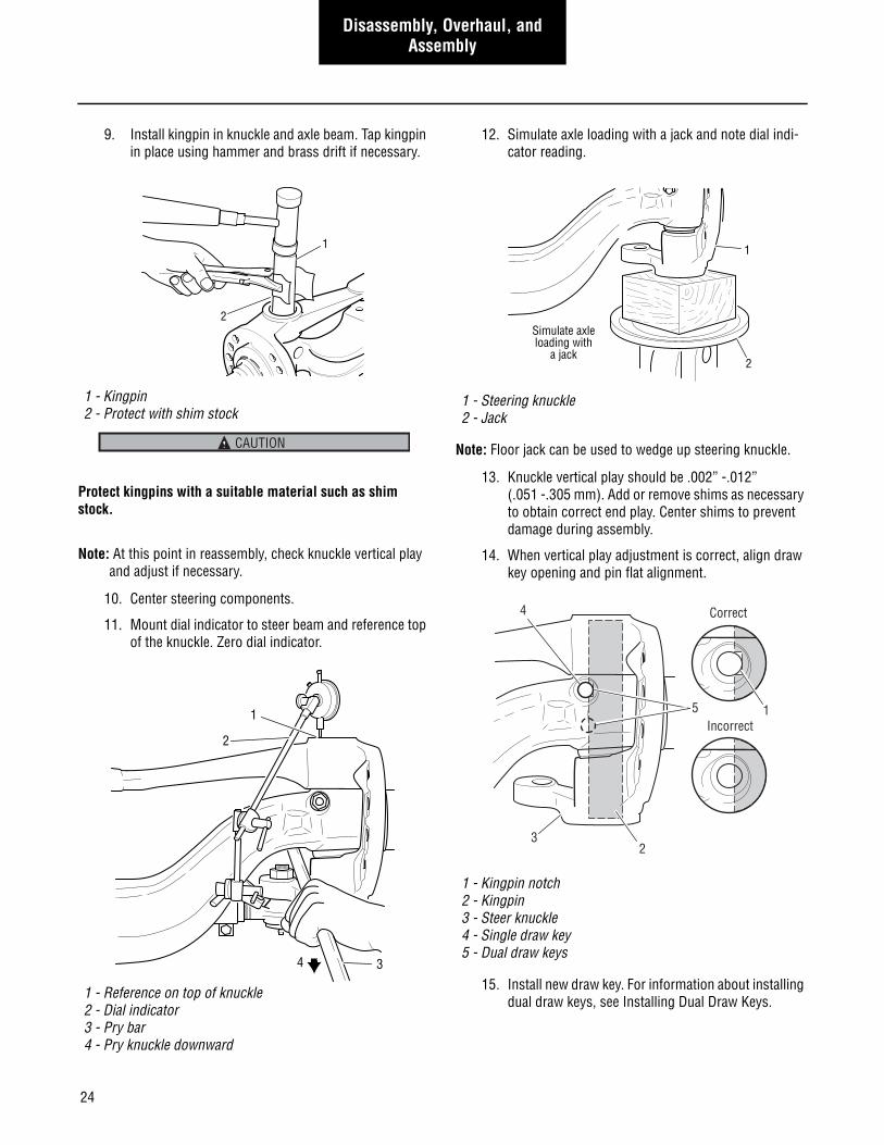
10. Center steering components.
11. Mount dial indicator to steer beam and reference top of the knuckle. Zero dial indicator.
12. Simulate axle loading with a jack and note dial indi-cator reading.
Note: Floor jack can be used to wedge up steering knuckle.
13. Knuckle vertical play should be .002” -.012” (.051 -.305 mm). Add or remove shims as necessary to obtain correct end play. Center shims to prevent damage during assembly.
14. When vertical play adjustment is correct, align draw key opening and pin flat alignment.
15. Install new draw key. For information about installing dual draw keys, see Installing Dual Draw Keys.
1 - Kingpin2 - Protect with shim stock
1 - Reference on top of knuckle2 - Dial indicator3 - Pry bar4 - Pry knuckle downward
1
2
CAUTION
2
1
34
1 - Steering knuckle2 - Jack
1 - Kingpin notch2 - Kingpin3 - Steer knuckle4 - Single draw key5 - Dual draw keys
Simulate axleloading with
a jack2
1
Correct
Incorrect
23
15
4
25
Disassembly, Overhaul, and Assembly
Disassembly, Overhaul,
and Assembly
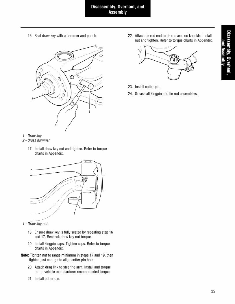
16. Seat draw key with a hammer and punch.
17. Install draw key nut and tighten. Refer to torque charts in Appendix.
18. Ensure draw key is fully seated by repeating step 16 and 17. Recheck draw key nut torque.
19. Install kingpin caps. Tighten caps. Refer to torque charts in Appendix.
Note: Tighten nut to range minimum in steps 17 and 19, then tighten just enough to align cotter pin hole.
20. Attach drag link to steering arm. Install and torque nut to vehicle manufacturer recommended torque.
21. Install cotter pin.
22. Attach tie rod end to tie rod arm on knuckle. Install nut and tighten. Refer to torque charts in Appendix.
23. Install cotter pin.
24. Grease all kingpin and tie rod assemblies.
1 - Draw key2 - Brass hammer
1 - Draw key nut
1
2
1
26
Disassembly, Overhaul, and Assembly
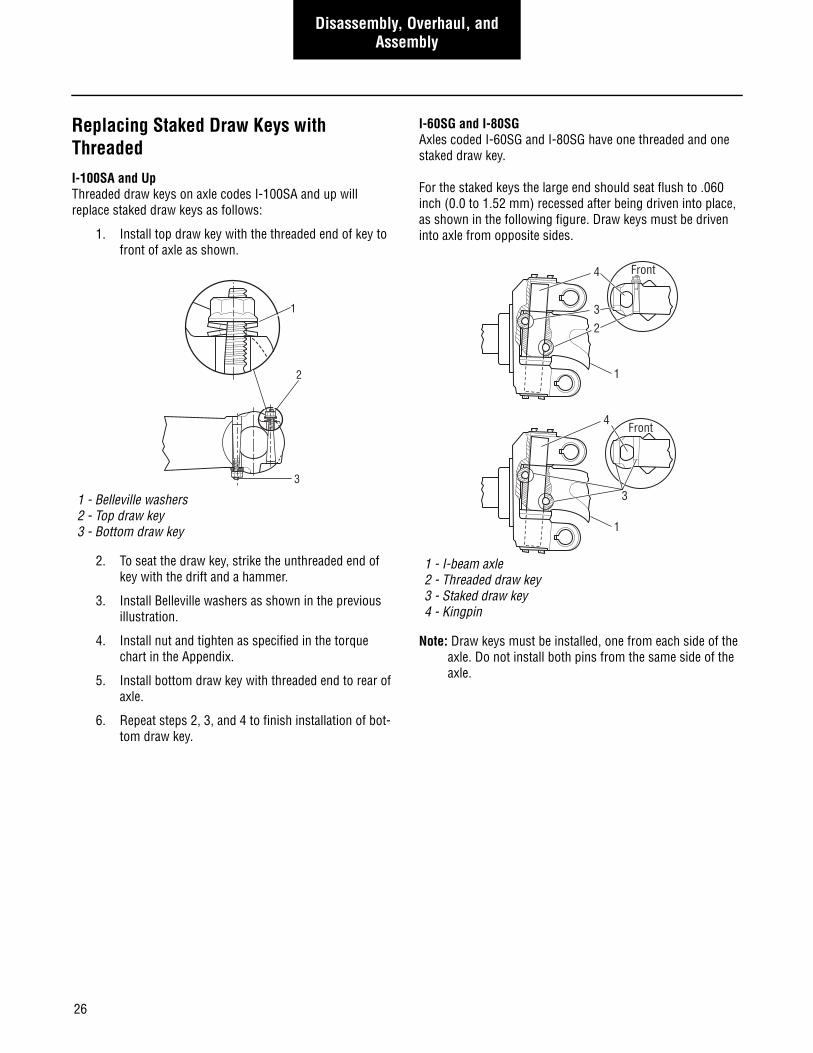
Replacing Staked Draw Keys with ThreadedI-100SA and UpThreaded draw keys on axle codes I-100SA and up will replace staked draw keys as follows:
1. Install top draw key with the threaded end of key to front of axle as shown.
2. To seat the draw key, strike the unthreaded end of key with the drift and a hammer.
3. Install Belleville washers as shown in the previous illustration.
4. Install nut and tighten as specified in the torque chart in the Appendix.
5. Install bottom draw key with threaded end to rear of axle.
6. Repeat steps 2, 3, and 4 to finish installation of bot-tom draw key.
I-60SG and I-80SGAxles coded I-60SG and I-80SG have one threaded and one staked draw key.
For the staked keys the large end should seat flush to .060 inch (0.0 to 1.52 mm) recessed after being driven into place, as shown in the following figure. Draw keys must be driven into axle from opposite sides.
Note: Draw keys must be installed, one from each side of the axle. Do not install both pins from the same side of the axle.
1 - Belleville washers2 - Top draw key3 - Bottom draw key
1
2
3
1 - I-beam axle2 - Threaded draw key3 - Staked draw key4 - Kingpin
4
4
3
3
2
1
1
Front
Front
27
Disassembly, Overhaul, and Assembly
Disassembly, Overhaul,
and Assembly
E-14621
1. Align the draw key opening and the pin flat align-ment.
2. Install new draw key.
Note: Draw keys must be installed from one side of the axle. Do not install pin on either side on the axle
3. Seat draw key with a hammer and punch.
4. Install draw key spring washers as shown.
5. Install draw key nut and tighten as specified in the torque chart in the Appendix.
6. Ensure that draw key is fully seated by reseating with a hammer and punch.
7. Recheck draw key nut torque.
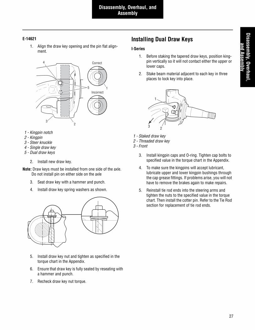
Installing Dual Draw KeysI-Series
1. Before staking the tapered draw keys, position king-pin vertically so it will not contact either the upper or lower caps.
2. Stake beam material adjacent to each key in three places to lock key into place.
3. Install kingpin caps and O-ring. Tighten cap bolts to specified value in the torque chart in the Appendix.
4. To make sure the kingpins will accept lubricant, lubricate upper and lower kingpin bushings through the cap grease fittings. If problems arise, you will not have to remove the brakes again to make repairs.
5. Reinstall tie rod ends into the steering arms and tighten the nuts to the specified value in the torque chart. Then install the cotter pin. Refer to the Tie Rod section for replacement of tie rod ends.
1 - Kingpin notch2 - Kingpin3 - Steer knuckle4 - Single draw key5 - Dual draw keys
Correct
Incorrect
23
15
4
1 - Staked draw key2 - Threaded draw key3 - Front
1
23
28
General Specifications
General Specifications
Wheel Bearing Adjustment
End-play .001”-.005” (.025-.125 mm)
(See Wheel Bearing Adjustment for adjustment procedure).
Wheel Alignment
(See vehicle manufacturer for specifications).
Kingpin Clearance – New
Vertical –.002”-.012” (.051-.305 mm)
(See Steering Knuckle Assembly.)
Kingpin Clearance – In Service
Vertical – .040” max. (1.016 mm)
(See Component Inspection.)
Lateral –.015” max. (.381 mm)
(See Bushing Inspection.)Note: Correct tightening torque values are extremely impor-
tant to assure long axle life and dependable perfor-mance. Under-tightening of attaching parts is just as harmful as over-tightening.
Note: Exact compliance with recommended torque values will assure the best results.
Note: Some applications use 5/8-18-UNF for this fastener. The same torque values apply.
Bolt head markings forgrade indentification
Grade 5 Grade 8
Kingpin Bushing SpecificationsThe chart below should be used if installing kingpin bushings that require reaming. Read instruction sheet included with the ser-vice kit or bushing BEFORE installing them.
SPICERMODEL
E-1000IE-1200IE-1203IE-1320I
E-1460I E-1202IE-1322I E-1462IEFA-18F3EFA-20F4
EFA-12F4EFA-13F5
I-60SGI-80SGD-600ND-700FD-700ND-800FD-800W
I-100SA/SGI-120SA/SGI-130SG I-130WI-140SA/SGI-146SA/SG
I-160SGI-180SGI-200SG D-2000F D-2200F
in.(mm)
in.(mm)
in.(mm)
in.(mm)
in.(mm)
in.(mm)
Kingpin Bushing Diameter I.D.
1.7960-1.7950(45.618-45.593)
1.8750-1.8740(47.625-47.600)
1.6275-1.6265(41.339-41.313)
1.3600-1.3615(34.544-34.582)
1.8608-1.8652(47.264-47.376)
2.0470-2.0514(51.994-52.105)
Kingpin Diameter
1.7937-1.7935(45.560-45.555)
1.8729-1.8725(47.572-47.562)
1.6255-1.6250(41.288-41.275)
1.3587-1.3592(34.511-34.524)
1.8595-1.8600(47.231-47.244)
2.0457-2.0462(51.973-51.986)
I-Beam Bore Diameter
1.7959-1.7945(45.616-45.580)
1.8749-1.8735(47.623-47.587)
1.6270-1.6260(41.326-41.300)
1.3597-1.3607(34.536-34.562)
1.8608-1.8622(47.264-47.300)
2.0470-2.0480(51.994-52.019)
29
General SpecificationsGeneral Specifications
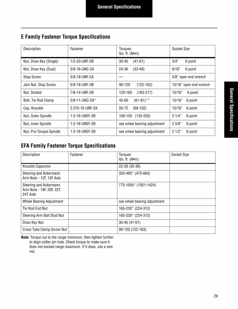
E Family Fastener Torque Specifications
EFA Family Fastener Torque Specifications
Note: Torque nut to the range minimum, then tighten further to align cotter pin hole. Check torque to make sure it does not exceed range maximum. If it does, use a new nut.
Description Fastener Torqueslbs. ft. (N•m)
Socket Size
Nut, Draw Key (Single) 1/2-20-UNF-2B 30-45 (41-61) 3/4” 6 point
Nut, Draw Key (Dual) 3/8-16-UNC-2A 24-36 (33-49) 9/16” 6 point
Stop Screw 5/8-18-UNF-2A — 5/8” open end wrench
Jam Nut, Stop Screw 5/8-18-UNF-3B 90-120 (122-163) 15/16” open end wrench
Nut, Slotted 7/8-14-UNF-2B 120-160 (163-217) 15/16” 6 point
Bolt, Tie Rod Clamp 5/8-11-UNC-2A* 45-60 (61-81)** 15/16” 6 point
Cap, Knuckle 2.375-16-UNF-2A 50-75 (68-102) 15/16” 6 point
Nut, Outer Spindle 1.5-18-UNEF-2B 100-150 (135-203) 2 1/4” 6 point
Nut, Inner Spindle 1.5-18-UNEF-2B see wheel bearing adjustment 2 5/8” 6 point
Nut, Pro-Torque Spindle 1.5-18-UNEF-2B see wheel bearing adjustment 2 1/2” 6 point
Description Fastener Torqueslbs. ft. (N•m)
Socket Size
Knuckle Capscrew 22-28 (30-38)
Steering and Ackermann Arm Nuts - 12F, 13F Axle
350-490* (475-664)
Steering and Ackermann Arm Nuts - 18F, 20F, 22T, 24T Axle
775-1050* (1051-1424)
Wheel Bearing Adjustment see wheel bearing adjustment
Tie Rod End Nut 165-230* (224-312)
Steering Arm Ball Stud Nut 165-230* (224-312)
Draw Key Nut 30-45 (41-61)
Cross Tube Clamp Screw Nut 90-120 (122-163)
30
General Specifications
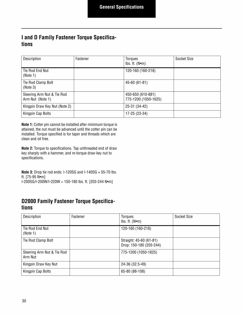
I and D Family Fastener Torque Specifica-tions
Note 1: Cotter pin cannot be installed after minimum torque is attained, the nut must be advanced until the cotter pin can be installed. Torque specified is for taper and threads which are clean and oil free.
Note 2: Torque to specifications. Tap unthreaded end of draw key sharply with a hammer, and re-torque draw key nut to specifications.
Note 3: Drop tie rod ends: I-120SG and I-140SG = 55-70 lbs. ft. [75-95 N•m]I-200SG/I-200W/I-220W = 150-180 lbs. ft. [203-244 N•m]
D2000 Family Fastener Torque Specifica-tions
Description Fastener Torqueslbs. ft. (N•m)
Socket Size
Tie Rod End Nut (Note 1)
120-160 (160-218)
Tie Rod Clamp Bolt (Note 3)
45-60 (61-81)
Steering Arm Nut & Tie Rod Arm Nut (Note 1)
450-650 (610-881)775-1200 (1050-1625)
Kingpin Draw Key Nut (Note 2) 25-31 (34-42)
Kingpin Cap Bolts 17-25 (23-34)
Description Fastener Torqueslbs. ft. (N•m)
Socket Size
Tie Rod End Nut (Note 1)
120-160 (160-218)
Tie Rod Clamp Bolt Straight: 45-60 (61-81) Drop: 150-180 (203-244)
Steering Arm Nut & Tie Rod Arm Nut
775-1200 (1050-1625)
Kingpin Draw Key Nut 24-36 (32.5-49)
Kingpin Cap Bolts 65-80 (88-108)
31
Wheel Bearing AdjustmentW
heel Bearing Adjustment
Wheel Bearing Adjustment
Proper wheel bearing adjustment maximizes wheel bearing and seal life. Proper adjustment can also extend brake lining life by preventing lining contamination caused by seal leaks.
1. Inspect the spindle threads and spindle nuts for cor-rosion and clean thoroughly or replace as required.
Note: Proper assembly and adjustment is not possible if the spindle threads or adjusting nuts are corroded.
2. Pre-lubricate all bearings.
3. Install the inner bearing into the hub and install the wheel seal.
4. If grease lubricant is used, fill the hub cavity with the appropriate lubricant.
5. Install the hub on the spindle with care, to prevent damage or distortion to the wheel seal.
Never mix grease and oil lubricants.
6. Install:
• The outer bearing on the spindle.
• The inner spindle nut onto the spindle.
7. Seat the bearings by tightening the inner nut to 200 lbs. ft. (135 N•m) while rotating the hub.
8. Loosen the inner nut one full turn.
9. Re-tighten the inner nut to 50 lbs. ft. (68 N•m) while rotating the hub.
10. Again loosen the inner nut one third turn (to one half turn maximum–three to five hub studs for a ten stud pattern).
11. Install the locking spindle washer.
Note: If the dowel pin and washer are not aligned, remove washer, turn it over and re-install. If required, loosen the inner nut just enough for alignment.
Never tighten inner nut to align dowel pin hole. This can pre-load the bearing and cause premature bearing failure.
12. Install:
• The retainer washer.
• The outer spindle nut.
13. Tighten the outer nut to 200±50 lbs. ft. (271-407 N•m).
14. Secure outer nut by bending the retainer washer over one flat hex on the outer spindle nut.
15. Verify that the wheel end play is between .001" and .005" (.025 and .125 mm) using a dial indicator. If reading does not fall within this range, repeat this procedure.
16. Attach hub cap.
17. If oil lubricant is used, fill the hub cavity with the appropriate lubricant. Install oil fill plug and tighten to specified torque.
Never mix grease and oil lubricants.
Note: For steer axles with Spicer in axle speed sensors, see AXSM-0034 for service and adjustment.
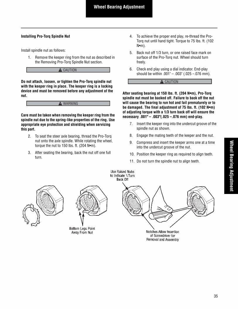
1 - Retainer washer2 - Locking spindle washer3 - Inner spindle nut4 - Steering knuckle spindle5 - Dowel pin6 - Outer spindle nut
CAUTION
3
6
2
4
5
1
CAUTION
CAUTION
32
Wheel Bearing Adjustment
Stamped Locking Nut System
Proper wheel bearing adjustment maximizes wheel bearing and seal life. Proper adjustment can also extend brake lining life by preventing lining contamination caused by seal leaks.
1. Inspect the spindle threads and spindle nut for cor-rosion and clean thoroughly or replace as required.
2. Pre-lubricate all bearings.
3. Install the inner bearing into the hub and install the wheel seal.
4. If grease lubricant is used, fill the hub cavity with the appropriate lubricant.
5. Install the hub on the spindle with care, to prevent damage or distortion to the wheel seal.
Never mix grease and oil lubricants.
6. Install the outer bearing on the spindle.
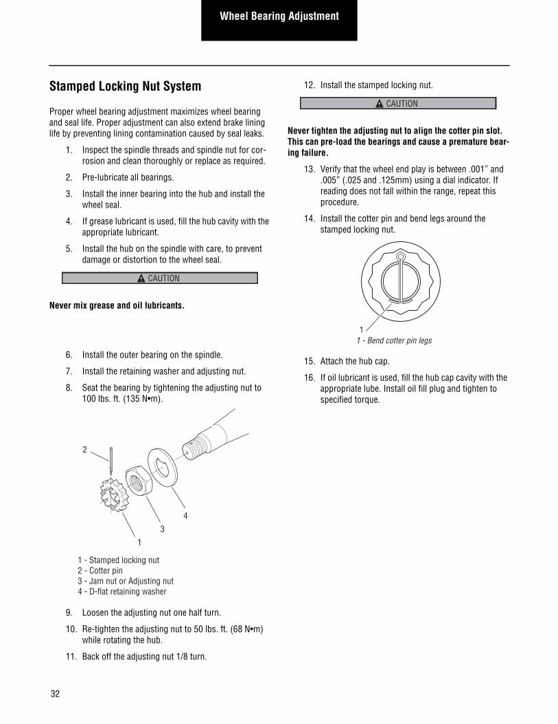
7. Install the retaining washer and adjusting nut.
8. Seat the bearing by tightening the adjusting nut to 100 lbs. ft. (135 N•m).
9. Loosen the adjusting nut one half turn.
10. Re-tighten the adjusting nut to 50 lbs. ft. (68 N•m) while rotating the hub.
11. Back off the adjusting nut 1/8 turn.
12. Install the stamped locking nut.
Never tighten the adjusting nut to align the cotter pin slot. This can pre-load the bearings and cause a premature bear-ing failure.
13. Verify that the wheel end play is between .001” and .005” (.025 and .125mm) using a dial indicator. If reading does not fall within the range, repeat this procedure.
14. Install the cotter pin and bend legs around the stamped locking nut.
15. Attach the hub cap.
16. If oil lubricant is used, fill the hub cap cavity with the appropriate lube. Install oil fill plug and tighten to specified torque.
CAUTION
4 3
1
2
1 - Stamped locking nut2 - Cotter pin3 - Jam nut or Adjusting nut4 - D-flat retaining washer
CAUTION
11 - Bend cotter pin legs
33
Wheel Bearing AdjustmentW
heel Bearing Adjustment
Single Nut (Castle Nut) Locking System1. Inspect the spindle threads and spindle nut for cor-
rosion and clean thoroughly or replace as required.
Note: Proper assembly and adjustment is not possible if the threads or adjusting nut are corroded.
2. Pre-lubricate all bearings.
3. Install the inner bearing into the hub and install the wheel seal.
4. If grease lubricant is used, fill the hub cavity with the appropriate lubricant.
5. Install the hub on the spindle with care, to prevent damage or distortion to the wheel seal.
Never mix grease and oil lubricants.
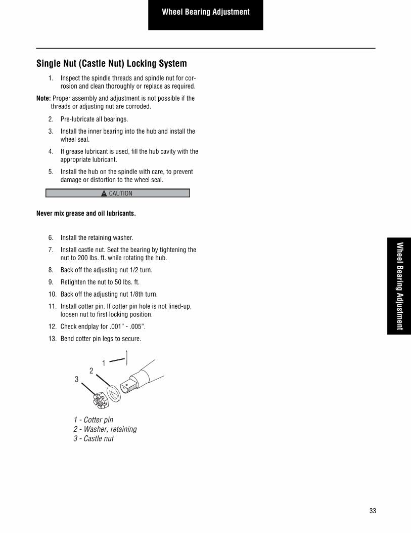
6. Install the retaining washer.
7. Install castle nut. Seat the bearing by tightening the nut to 200 lbs. ft. while rotating the hub.
8. Back off the adjusting nut 1/2 turn.
9. Retighten the nut to 50 lbs. ft.
10. Back off the adjusting nut 1/8th turn.
11. Install cotter pin. If cotter pin hole is not lined-up, loosen nut to first locking position.
12. Check endplay for .001” - .005”.
13. Bend cotter pin legs to secure.
CAUTION
1
32
1 - Cotter pin2 - Washer, retaining3 - Castle nut
34
Wheel Bearing Adjustment
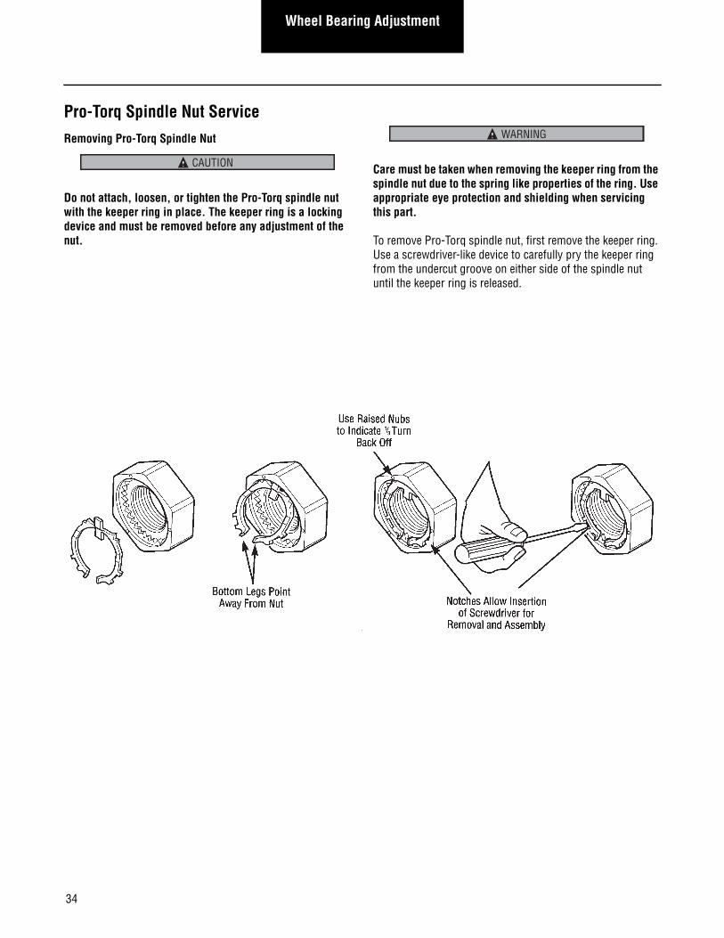
Pro-Torq Spindle Nut ServiceRemoving Pro-Torq Spindle Nut
Do not attach, loosen, or tighten the Pro-Torq spindle nut with the keeper ring in place. The keeper ring is a locking device and must be removed before any adjustment of the nut.
Care must be taken when removing the keeper ring from the spindle nut due to the spring like properties of the ring. Use appropriate eye protection and shielding when servicing this part.
To remove Pro-Torq spindle nut, first remove the keeper ring. Use a screwdriver-like device to carefully pry the keeper ring from the undercut groove on either side of the spindle nut until the keeper ring is released.
CAUTION
WARNING
35
Wheel Bearing AdjustmentW
heel Bearing Adjustment
Installing Pro-Torq Spindle Nut
Install spindle nut as follows:
1. Remove the keeper ring from the nut as described in the Removing Pro-Torq Spindle Nut section.
Do not attach, loosen, or tighten the Pro-Torq spindle nut with the keeper ring in place. The keeper ring is a locking device and must be removed before any adjustment of the nut.
Care must be taken when removing the keeper ring from the spindle nut due to the spring-like properties of the ring. Use appropriate eye protection and shielding when servicing this part.
2. To seat the steer axle bearing, thread the Pro-Torq nut onto the axle spindle. While rotating the wheel, torque the nut to 150 lbs. ft. (204 N•m).
3. After seating the bearing, back the nut off one full turn.
4. To achieve the proper end play, re-thread the Pro-Torq nut until hand tight. Torque to 75 lbs. ft. (102 N•m).
5. Back nut off 1/3 turn, or one raised face mark on surface of the Pro-Torq nut. Wheel should turn freely.
6. Check end play using a dial indicator. End-play should be within .001" – .003" (.025 –.076 mm).
After seating bearing at 150 lbs. ft. (204 N•m), Pro-Torq spindle nut must be backed off. Failure to back off the nut will cause the bearing to run hot and fail prematurely or to be damaged. The final adjustment of 75 lbs. ft. (102 N•m) of adjusting torque with a 1/3 turn back off will ensure the necessary .001" – .003"(.025 –.076 mm) end-play.
7. Insert the keeper ring into the undercut groove of the spindle nut as shown.
8. Engage the mating teeth of the keeper and the nut.
9. Compress and insert the keeper arms one at a time into the undercut groove of the nut.
10. Position the keeper ring as required to align teeth.
11. Do not turn the spindle nut to align teeth.
CAUTION
WARNING
CAUTION
36
Appendix
Special Service Tools
Special service tools are available from the below suppliers:
OTC DIVISION
Service Tools
655 Eisenhower Drive
Owatonna, MN 55060
Telephone: 1-800-533-0492
Fax Number: 1-800-283-8665
The following is a list of tools needed to service the front axles in this manual. These tool numbers are from OTC Tool Division. Dana makes no warranty or representation of these tools.
rebmuN looTnoitpircseDdecivreS sledoM
Tools to service all axle models Kingpin Bushing Basic Set ZTSE 4330A
Tools to service axle modelsI-60SG & I-80SG
Bushing InstallerSeal Installer
ZTSE 4330-4AZTSE 4330-44
Tools to service axle modelsI-100SA/SG through I-146SA/SG
Bushing InstallerSeal Installer
ZTSE 4330-5AZTSE 4330-55
Tools to service axle modelsI-160SA/SG through I-200SA/SG
Bushing InstallerSeal Installer
ZTSE 4330-3AZTSE 4330-33
37
Additional Service InformationAdditional Service
Information
Additional Service Information
Additional parts and service information on these and related Spicer products may be found in the following publications:
For the most current information visit the Dana website,www.dana.com. These publications may be oredered through the Spicer publications order system. An order form may be obtained by calling Dana Service Support.
Service Manuals
Parts Books
Brake
Foundation Brakes
Models ES (All Models) BRIP-0
BRSM-0033
In Axle Speed Sensor AXSM-0034
065
Steer Axles (All Models except “E” Family) AXIP-0090
Steer Axles E-1000, E-1002, E-1200, E-1202, E-1320, E-1322, E-1460, and E1462
AXIP-0075
38
Appendix
Appendix
Lubrication
Proper lubrication practices are important in maximizing the service life of your steer axle assembly.
Kingpins, Thrust Bearings and Tie Rod Ends
On-Highway Applications - StandardPressure lubricate every 6 months or 25,000 miles (40,000 km).
A more frequent lubrication cycle is required for axles used in on/off highway, refuse, or other severe service applications.
Use heavy-duty, multipurpose lithium base (#2 grade) grease. Do not mix with sodium base grease.Note: If it is difficult to grease either the upper or lower bush-
ing, try greasing the bushings with the vehicle jacked up and supported on axle stands to improve grease flow and help flush out contamination.
Wheel BearingsLubricate wheel bearings with an approved drive axle lubri-cant (oil bath) or heavy duty grease (grease packed) depend-ing on the type of axle lube system. Identify the type of lubrication system on your vehicle before servicing wheel bearings. Improper lubrication can result in reduced seal life and potential damage to bearings and spindles.
Oil BathLubricate wheel end assembly with a drive axle lubricant that meets MIL-L-2105D specifications. Either 80W-90 mineral based or 75W-90 synthetic lube is acceptable. Check lubricant level at each greasing interval. Maintain lube level to center-line of axle or fill line on hub cap. Always check lube level on flat ground.
Do not mix lubricants of different grades. Do not mix min-eral and synthetic lubes. Different brands of same grade may be mixed. Do not pack bearings with grease when using an oil bath system. This practice can restrict the flow of lubricant to the wheel seal.
Grease PackedThoroughly clean bearings, spindle, hub cap, and hub cavity. Parts may be washed in a suitable commercial solvent. Be certain parts are free of moisture or other contaminants. Refer to vehicle and/or wheel seal manufacturer’s recommendations when using grease. Fill wheel hub with grease to inside diam-eter of bearing cups. Fill hub cap. Grease bearing cones by forcing grease between rollers, cones, and cage.
Never mix oil bath and grease packed wheel ends.
LMS Bearing SystemRefer to Spicer information Bulletin ABIB-9606.
CAUTION
CAUTION
39
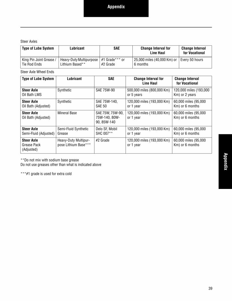
AppendixAppendix
**Do not mix with sodium base greaseDo not use greases other than what is indicated above
***#1 grade is used for extra cold
Steer Axles
Type of Lube System Lubricant SAE Change Interval for Line Haul
Change Interval for Vocational
King Pin Joint Grease / Tie Rod Ends
Heavy-Duty Multipurpose Lithium Based**
#1 Grade*** or #2 Grade
25,000 miles (40,000 Km) or 6 months
Every 50 hours
Steer Axle Wheel Ends
Type of Lube System Lubricant SAE Change Interval for Line Haul
Change Interval for Vocational
Steer AxleOil Bath LMS
Synthetic SAE 75W-90 500,000 miles (800,000 Km) or 5 years
120,000 miles (193,000 Km) or 2 years
Steer AxleOil Bath (Adjusted)
Synthetic SAE 75W-140, SAE 50
120,000 miles (193,000 Km) or 1 year
60,000 miles (95,000 Km) or 6 months
Steer AxleOil Bath (Adjusted)
Mineral Base SAE 75W, 75W-90, 75W-140, 80W-90, 85W-140
120,000 miles (193,000 Km) or 1 year
60,000 miles (95,000 Km) or 6 months
Steer AxleSemi-Fluid (Adjusted)
Semi-Fluid Synthetic Grease
Delo SF, Mobil SHC 007**
120,000 miles (193,000 Km) or 1 year
60,000 miles (95,000 Km) or 6 months
Steer AxleGrease Pack (Adjusted)
Heavy-Duty Multipur-pose Lithium Base***
#2 Grade 120,000 miles (193,000 Km) or 1 year
60,000 miles (95,000 Km) or 6 months
40
Appendix
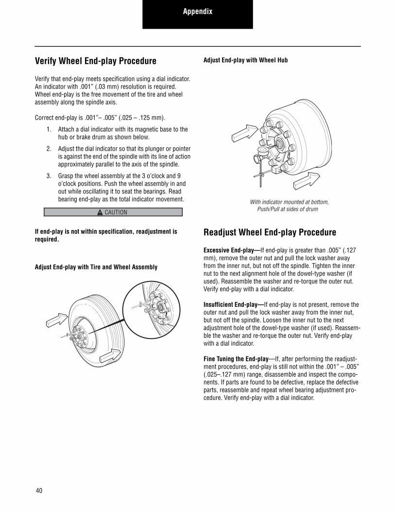
Verify Wheel End-play Procedure
Verify that end-play meets specification using a dial indicator. An indicator with .001” (.03 mm) resolution is required. Wheel end-play is the free movement of the tire and wheel assembly along the spindle axis.
Correct end-play is .001”– .005” (.025 – .125 mm).
1. Attach a dial indicator with its magnetic base to the hub or brake drum as shown below.
2. Adjust the dial indicator so that its plunger or pointer is against the end of the spindle with its line of action approximately parallel to the axis of the spindle.
3. Grasp the wheel assembly at the 3 o’clock and 9 o’clock positions. Push the wheel assembly in and out while oscillating it to seat the bearings. Read bearing end-play as the total indicator movement.
If end-play is not within specification, readjustment is required.
Adjust End-play with Tire and Wheel Assembly
Adjust End-play with Wheel Hub
Readjust Wheel End-play Procedure
Excessive End-play—If end-play is greater than .005” (.127 mm), remove the outer nut and pull the lock washer away from the inner nut, but not off the spindle. Tighten the inner nut to the next alignment hole of the dowel-type washer (if used). Reassemble the washer and re-torque the outer nut. Verify end-play with a dial indicator.
Insufficient End-play—If end-play is not present, remove the outer nut and pull the lock washer away from the inner nut, but not off the spindle. Loosen the inner nut to the next adjustment hole of the dowel-type washer (if used). Reassem-ble the washer and re-torque the outer nut. Verify end-play with a dial indicator.
Fine Tuning the End-play—If, after performing the readjust-ment procedures, end-play is still not within the .001” – .005” (.025–.127 mm) range, disassemble and inspect the compo-nents. If parts are found to be defective, replace the defective parts, reassemble and repeat wheel bearing adjustment pro-cedure. Verify end-play with a dial indicator.
CAUTION
With indicator mounted at bottom, Push/Pull at sides of drum

All applications must be approved by the Application Engineering Department. Specifications and/or design are subject to change without notice or obligation. Printed in USA AXSM-0038 05/11
For spec‘ing or service assistance, call 1-877-777-5360 or visit our website at www.dana.com
Dana Commercial Vehicle Products Group3939 Technology Drive
Maumee, Ohio, USA 43537
www.dana.com