Embed Size (px)
Citation preview
IA9000 SERIES
Digital Melting Point
Apparatus
Operating and Safety Instructions
2
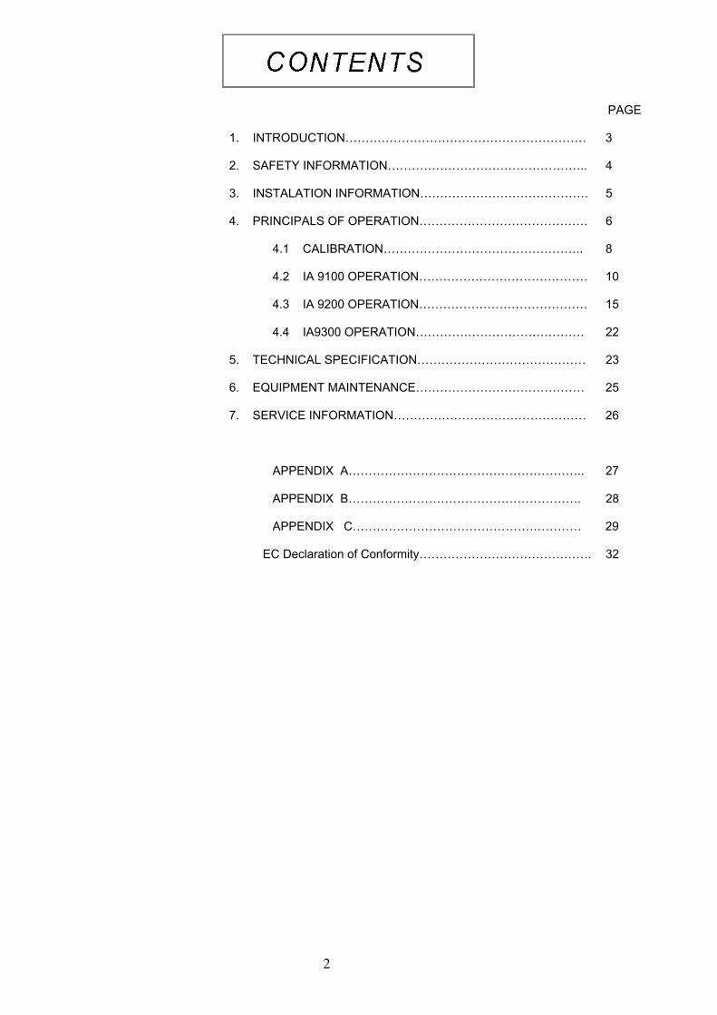
PAGE 1. INTRODUCTION…………………………………………………… 3 2. SAFETY INFORMATION………………………………………….. 4 3. INSTALATION INFORMATION…………………………………… 5 4. PRINCIPALS OF OPERATION…………………………………… 6
4.1 CALIBRATION………………………………………….. 8 4.2 IA 9100 OPERATION…………………………………… 10 4.3 IA 9200 OPERATION…………………………………… 15 4.4 IA9300 OPERATION…………………………………… 22
5. TECHNICAL SPECIFICATION…………………………………… 23 6. EQUIPMENT MAINTENANCE…………………………………… 25 7. SERVICE INFORMATION………………………………………… 26
APPENDIX A………………………………………………….. 27 APPENDIX B…………………………………………………. 28 APPENDIX C………………………………………………… 29
EC Declaration of Conformity……………………………………. 32
3
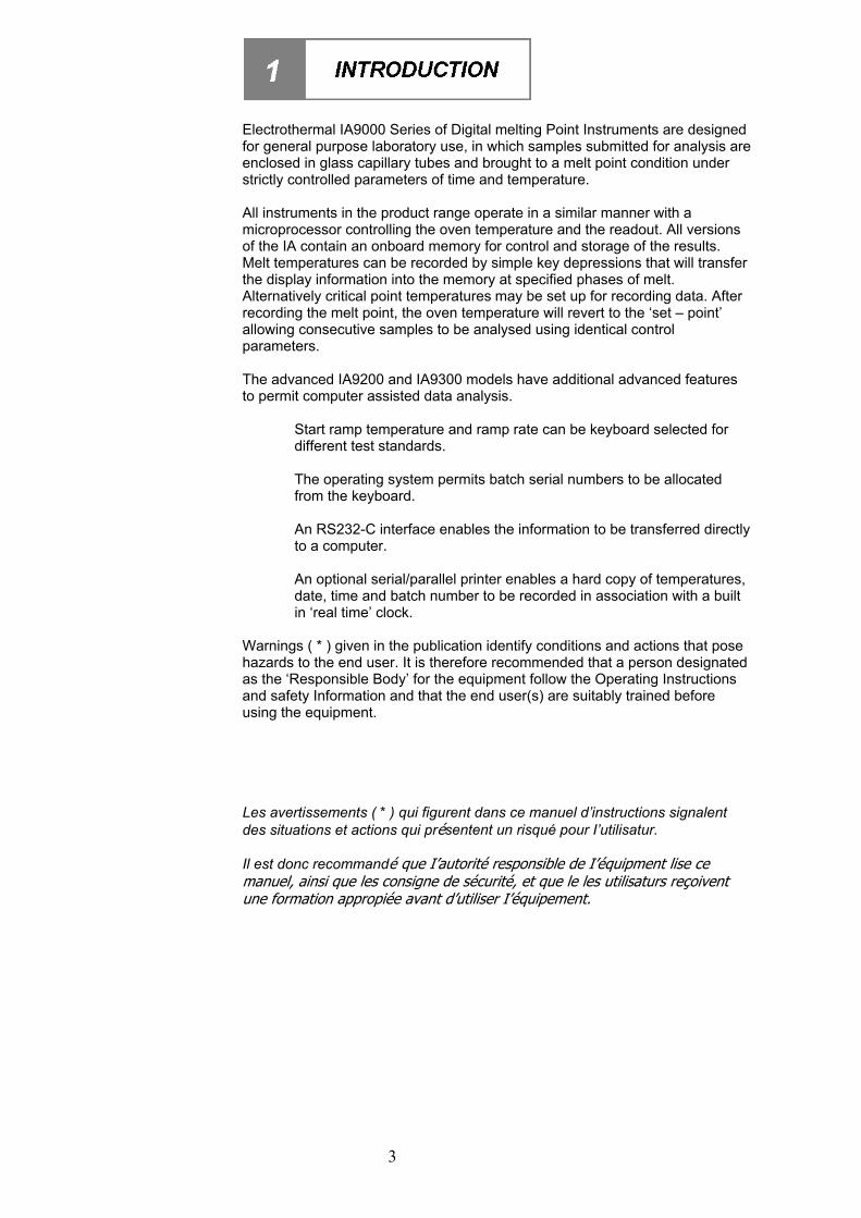
Electrothermal IA9000 Series of Digital melting Point Instruments are designed for general purpose laboratory use, in which samples submitted for analysis are enclosed in glass capillary tubes and brought to a melt point condition under strictly controlled parameters of time and temperature. All instruments in the product range operate in a similar manner with a microprocessor controlling the oven temperature and the readout. All versions of the IA contain an onboard memory for control and storage of the results. Melt temperatures can be recorded by simple key depressions that will transfer the display information into the memory at specified phases of melt. Alternatively critical point temperatures may be set up for recording data. After recording the melt point, the oven temperature will revert to the ‘set – point’ allowing consecutive samples to be analysed using identical control parameters. The advanced IA9200 and IA9300 models have additional advanced features to permit computer assisted data analysis.
Start ramp temperature and ramp rate can be keyboard selected for different test standards. The operating system permits batch serial numbers to be allocated from the keyboard. An RS232-C interface enables the information to be transferred directly to a computer. An optional serial/parallel printer enables a hard copy of temperatures, date, time and batch number to be recorded in association with a built in ‘real time’ clock.
Warnings ( * ) given in the publication identify conditions and actions that pose hazards to the end user. It is therefore recommended that a person designated as the ‘Responsible Body’ for the equipment follow the Operating Instructions and safety Information and that the end user(s) are suitably trained before using the equipment. Les avertissements ( * ) qui figurent dans ce manuel d’instructions signalent des situations et actions qui présentent un risqué pour I’utilisatur. Il est donc recommandé que I’autorité responsible de I’équipment lise ce manuel, ainsi que les consigne de sécurité, et que le les utilisaturs reçoivent une formation appropiée avant d’utiliser I’équipement.
4
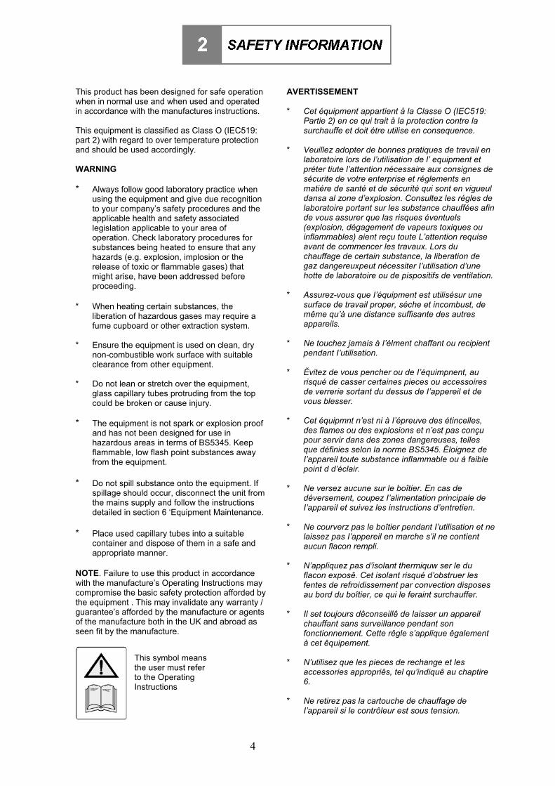
This product has been designed for safe operation when in normal use and when used and operated in accordance with the manufactures instructions. This equipment is classified as Class O (IEC519: part 2) with regard to over temperature protection and should be used accordingly. WARNING * Always follow good laboratory practice when
using the equipment and give due recognition to your company’s safety procedures and the applicable health and safety associated legislation applicable to your area of operation. Check laboratory procedures for substances being heated to ensure that any hazards (e.g. explosion, implosion or the release of toxic or flammable gases) that might arise, have been addressed before proceeding.
* When heating certain substances, the
liberation of hazardous gases may require a fume cupboard or other extraction system.
* Ensure the equipment is used on clean, dry
non-combustible work surface with suitable clearance from other equipment.
* Do not lean or stretch over the equipment,
glass capillary tubes protruding from the top could be broken or cause injury.
* The equipment is not spark or explosion proof
and has not been designed for use in hazardous areas in terms of BS5345. Keep flammable, low flash point substances away from the equipment.
* Do not spill substance onto the equipment. If
spillage should occur, disconnect the unit from the mains supply and follow the instructions detailed in section 6 ‘Equipment Maintenance.
* Place used capillary tubes into a suitable
container and dispose of them in a safe and appropriate manner.
NOTE. Failure to use this product in accordance with the manufacture’s Operating Instructions may compromise the basic safety protection afforded by the equipment . This may invalidate any warranty / guarantee’s afforded by the manufacture or agents of the manufacture both in the UK and abroad as seen fit by the manufacture.
AVERTISSEMENT * Cet équipment appartient å la Classe O (IEC519:
Partie 2) en ce qui trait å la protection contre la surchauffe et doit étre utilise en consequence.
* Veuillez adopter de bonnes pratiques de travail en
laboratoire lors de l’utilisation de l’ equipment et préter tiute l’attention nécessaire aux consignes de sécurite de votre enterprise et réglements en matiére de santé et de sécurité qui sont en vigueul dansa al zone d’explosion. Consultez les régles de laboratoire portant sur les substance chauffées afin de vous assurer que las risques éventuels (explosion, dégagement de vapeurs toxiques ou inflammables) aient reçu toute L’attention requise avant de commencer les travaux. Lors du chauffage de certain substance, la liberation de gaz dangereuxpeut nécessiter I’utilisation d’une hotte de laboratoire ou de pispositifs de ventilation.
* Assurez-vous que I’équipment est utilisésur une
surface de travail proper, séche et incombust, de même qu’à une distance suffisante des autres appareils.
* Ne touchez jamais à I’élment chaffant ou recipient
pendant I’utilisation. * !vitez de vous pencher ou de I’équimpnent, au
risqué de casser certaines pieces ou accessoires de verrerie sortant du dessus de I’appereil et de vous blesser.
* Cet équipmnt n’est ni à I’épreuve des étincelles,
des flames ou des explosions et n’est pas conçu pour servir dans des zones dangereuses, telles que définies selon la norme BS5345. !loignez de I’appareil toute substance inflammable ou á faible point d d’éclair.
* Ne versez aucune sur le boîtier. En cas de
déversement, coupez I’alimentation principale de I’appareil et suivez les instructions d’entretien.
* Ne courverz pas le boîtier pendant I’utilisation et ne
laissez pas I’appereil en marche s’il ne contient aucun flacon rempli.
* N’appliquez pas d’isolant thermiquw ser le du
flacon exposê. Cet isolant risqué d’obstruer les fentes de refroidissement par convection disposes au bord du boîtier, ce qui le feraint surchauffer.
* Il set toujours dêconseillê de laisser un appareil
chauffant sans surveillance pendant son fonctionnement. Cette rêgle s’applique êgalement à cet êquipement.
* N’utilisez que les pieces de rechange et les
accessories appropriês, tel qu’indiquê au chaptire 6.
* Ne retirez pas la cartouche de chauffage de
I’appareil si le contrôleur est sous tension.
This symbol means the user must refer to the Operating Instructions
5
INSTALLATION INSTRUCTIONS: The equipment is Installation category (Over Voltage category) Class II with regard to protection against electric shock (IEC 664 Sub Clause 5.6). Environment operation conditions: indoor use only; temperatures 5°C to 40°C, 80% RH maximum; mains supply voltage fluctuations not to exceed !10%. The equipment power supply unit must be connected to a fixed ground earthed (grounded) mains socket outlet. If the unit is supplied without a fitted mains plug the following connections must be made. (If in doubt consult a qualified Electrician). Green / Yellow or Green = Protected earth (ground) Blue or White = Neutral (Negative) (-) Brown or Black = Line (Live – positive) (+) This equipment is supplied with a universal input voltage power supply. Only use the power supply with the equipment supplied. Only use the equipment with the supplied power supply unit. For additional safety it is recommended the unit be connected inline to a RCD (Residual Current Device) or GFI (Ground fault interrupter) in the U.S.A. Environmental Protection It is the policy of Thermo Fisher Scientific to give consideration to environmental issues in design and manufacturing without compromising end product performance and value.
Packaging materials have been selected such that they may be assorted for recycling. Main case Materials are moulded in ABS plastic.
At the end of your product and accessories life, it must not be discarded as domestic waste. Ref: EU Directive 2002/96/EC on Waste Electrical and Electronic Equipment Directive (WEEE). Please contact your distributor / supplier for further information. For end users outside of the EU consult applicable regulations.
The IA9200 & IA9300 products contain Nickel Metal Hydride batteries (NI MH). Battery replacement should only be performed by the manufacture or service agent acting on behalf of the manufacturer. End of life battery removal should also only be performed by an authorised recycling company. Battery removal will cause loss of memory data. Battery removal invalidates manufacturer’s warranty. End of Life battery removal: Remove base and unsolder the NI MH battery from the PCBA. Always dispose of batteries in an environmentally friendly manner
This product should only be dismantled for recycling by an authorised recycling company.
Thermo Fisher Scientific is registered as Electrothermal Engineering Limited with the Environment Agency as a producer of WEEE through an authorised compliance scheme.
6
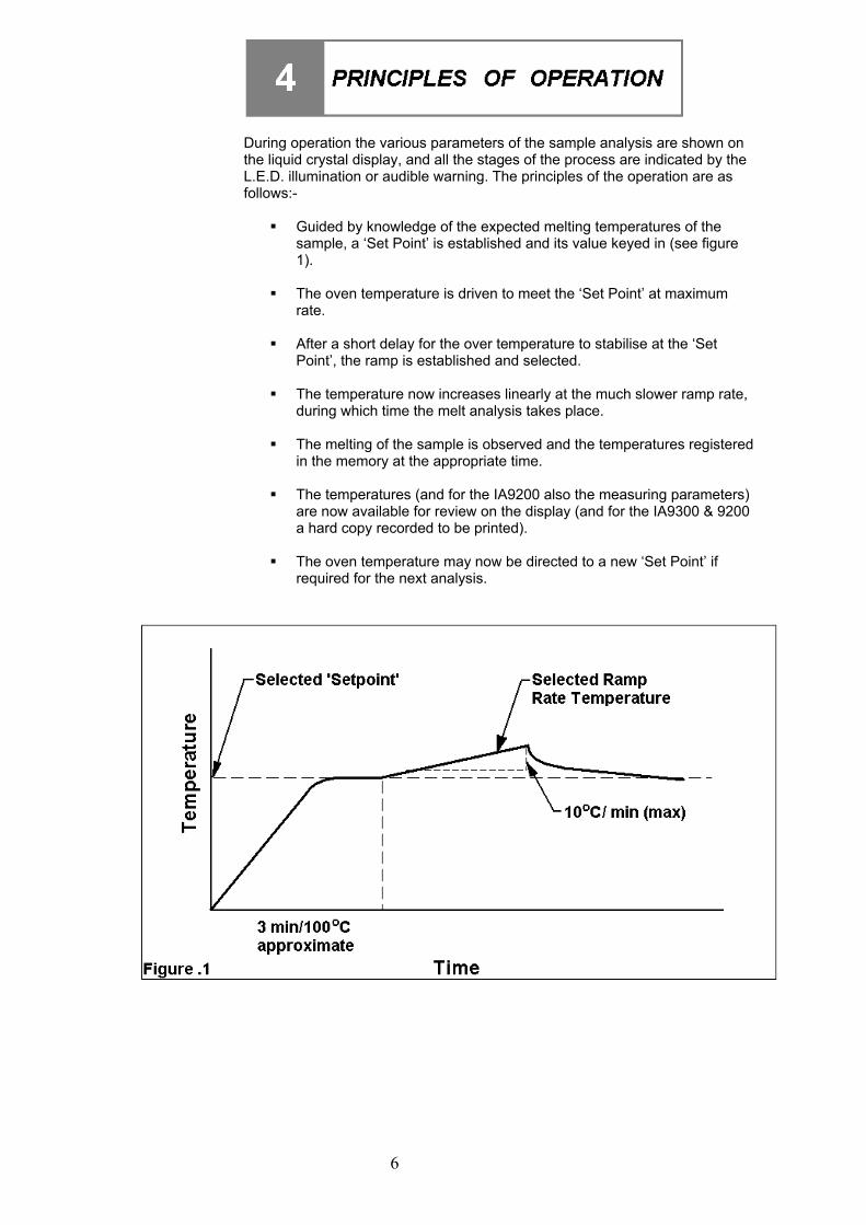
During operation the various parameters of the sample analysis are shown on the liquid crystal display, and all the stages of the process are indicated by the L.E.D. illumination or audible warning. The principles of the operation are as follows:-
! Guided by knowledge of the expected melting temperatures of the sample, a ‘Set Point’ is established and its value keyed in (see figure 1).
! The oven temperature is driven to meet the ‘Set Point’ at maximum
rate.
! After a short delay for the over temperature to stabilise at the ‘Set Point’, the ramp is established and selected.
! The temperature now increases linearly at the much slower ramp rate,
during which time the melt analysis takes place.
! The melting of the sample is observed and the temperatures registered in the memory at the appropriate time.
! The temperatures (and for the IA9200 also the measuring parameters)
are now available for review on the display (and for the IA9300 & 9200 a hard copy recorded to be printed).
! The oven temperature may now be directed to a new ‘Set Point’ if
required for the next analysis.
7
Preparation of Samples
To obtained the best results, the samples under test / observation should be perfectly dry. Drying is best accomplished by storing the samples overnight in a vacuum desiccator over a suitable drying agent such as phosphourus pentoxide. A drying method must be employed in the case of hygroscopic samples. Provided the sample is dry there is usually little difficulty in introducing the small amount required into the capillary tube. Tapping the tube on the bench to compact the material at the base of the tube. It is important not to use too large a sample, a quantity occupying no more than 1-2 mm of the bottom of the tube should be used. If this is exceeded, accurate and sharp melting point may not be obtained. Care should be taken to see the sample beds down to the bottom of the tube, as large are pockets can cause difficulty. Determination of Melting point. In recording melting points, the operator may wish to observe four distinct phases: a) First signs of change (darkening, shrivelling, sintering, ect). These changes
may be due to loss of solvent or crystallization. Occasionally one can see the solvent condensing on the cooler portion of the tube.
b) First signs of liquid formation.
c) Formation of meniscus.
d) Formation of a completely clear liquid.
Not all compounds will behave in this manner however. With many, especially where the material is in a high state of purity, no change may be seen before any liquid appears. Some materials will be seen to sublime, rather than melt above 300°C Decomposition may often be accompanied by evolution of gas. Pure compounds will be expected to pass through the 3 stages a) c) and d), within a range of 1°C. Interpretation of Results. It is generally accepted the formation of a meniscus should be regarded as the figure to be recorded for a single temperature melting point. Where a range is quoted, it can generally be assumed reference is being made to stages b) to d) inclusive. The range will generally cover no more than 1°C for pure compounds, but may well extend to 3 to 4°C for others. The range will often be grater when decomposition or sublimation is experienced. When using the equipment to determine the melting point of more than one sample of the same compound at a time, the average of the meniscus temperature (onset of melt) should be taken. Calibration Procedure. For equipment calibration purposes and to minimise variation between repeat measurements, it is recommended that onset of melt observations are used against Certified Reference Material stated onset figures. The measurements should be taken using 2mm diameter capillary tubes.
8
Calibration must be carried out annually, or whenever the performance of the apparatus is suspected e.g. when similar successive test produce markedly divergent results. The apparatus must either be returned to the dealer for calibration, or calibration must be carried out in the following manner, using Calibration Kit AZ6730 and the standard chemicals Carbazole (AZ9118) and P-nitrotoluene (AZ9218). To check if the unit is still in calibration proceed as follows:- a) Switch the unit on and ensure the instrument components are in the
stable condition as described in Section 4 or 18. b) Perform a melt with each standard chemicals and note the reading.
c) Compare the results obtained with the melting points shown on the
certificates supplied with each chemical and ascertain whether the unit performs within acceptable limits.
d) If it is decided that re-calibration is required proceed as follows:-
1. Switch off the unit and allow it to cool. 2. Disconnect Power supply from the rear of the unit.
3. Invert the unit and remove the three screws securing the base
plate to the body.
4. Place the unit on the bench the correct way up taking care not to let the base fall from the unit. Lift the body from the base plate.
5. Turn the body on its side and placed it on the bench to the right of
the base plate.
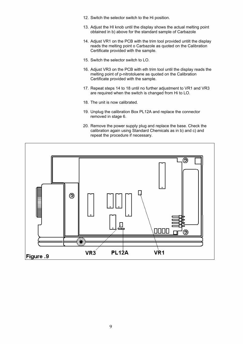
6. Remove the two pin connector from PL1 2A on the printed circuit board.
7. Plug in the calibration box into pin connector PL 12A.
8. Switch the selector switch to the LO position.
9. Insert the power plug on the instrument and switch on.
10. Allow the instrument to re-stabilise. It should not be necessary to
go through the ‘Set-point’ procedure again at this stage. 2 to 3 minutes should suffice to ensure stabilisation.
11. Adjust the LO knob until the display shows the actual melting point
obtained in b) above for the standard sample of p-nitrotoluene.
9
12. Switch the selector switch to the Hi position. 13. Adjust the HI knob until the display shows the actual melting point
obtained in b) above for the standard sample of Carbazole
14. Adjust VR1 on the PCB with the trim tool provided untilt the display reads the melting point o Carbazole as quoted on the Calibration Certificate provided with the sample.
15. Switch the selector switch to LO.
16. Adjust VR3 on the PCB with eth trim tool until the display reads the
melting point of p-nitrotoluene as quoted on the Calibration Certificate provided with the sample.
17. Repeat steps 14 to 18 until no further adjustment to VR1 and VR3
are required when the switch is changed from Hi to LO.
18. The unit is now calibrated.
19. Unplug the calibration Box PL12A and replace the connector removed in stage 6.
20. Remove the power supply plug and replace the base. Check the
calibration again using Standard Chemicals as in b) and c) and repeat the procedure if necessary.
10
Upon receipt of the instrument proceed consecutively as follows:- 4.2.1 Power Supply.
The power supply supplied with your new IA 9100 supports all A.C. Mains supply voltages within the range of 100V to 240V inclusive at 50-60Hz. Do not use the power supply with a D.C. supply voltage or in conjunction with any type of voltage regulation equipment. Do not use with a mains supply supplying power at a different frequency other than that stated.
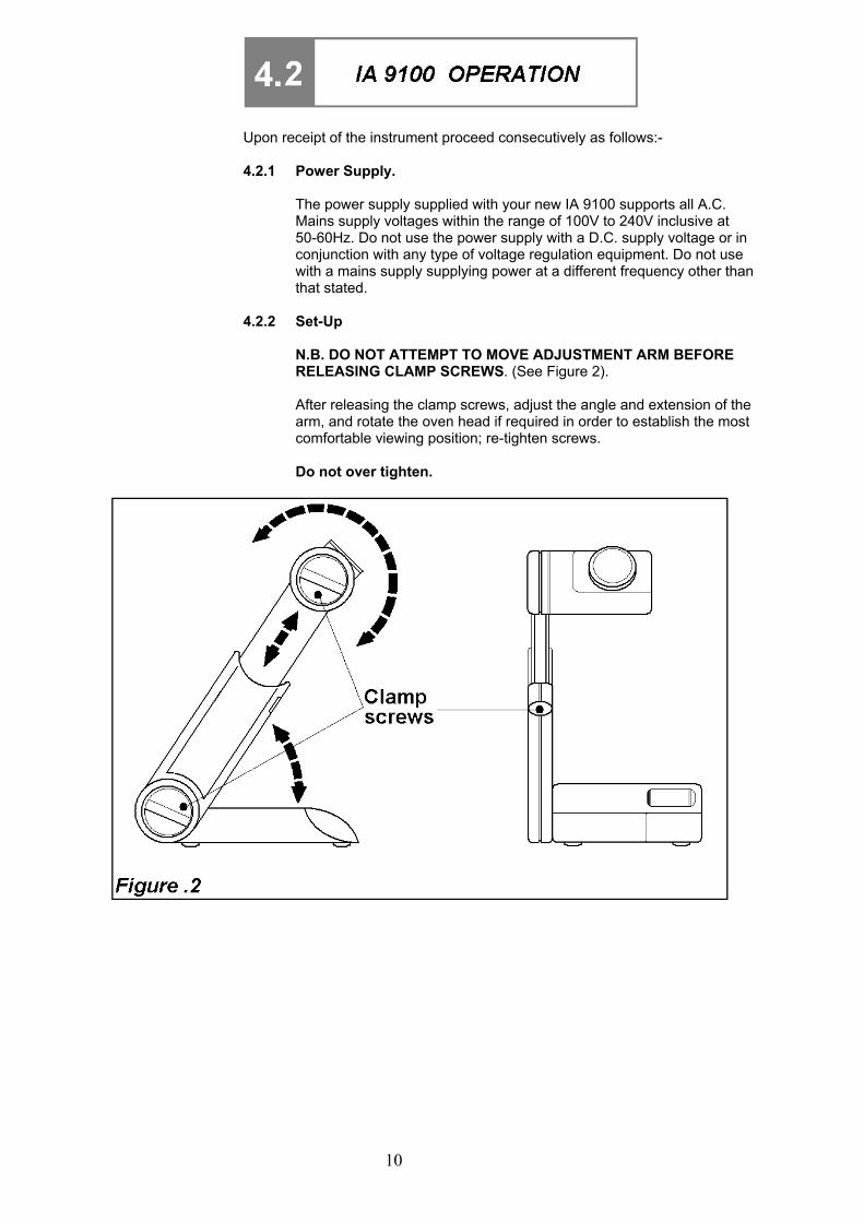
4.2.2 Set-Up
N.B. DO NOT ATTEMPT TO MOVE ADJUSTMENT ARM BEFORE RELEASING CLAMP SCREWS. (See Figure 2). After releasing the clamp screws, adjust the angle and extension of the arm, and rotate the oven head if required in order to establish the most comfortable viewing position; re-tighten screws. Do not over tighten.
11
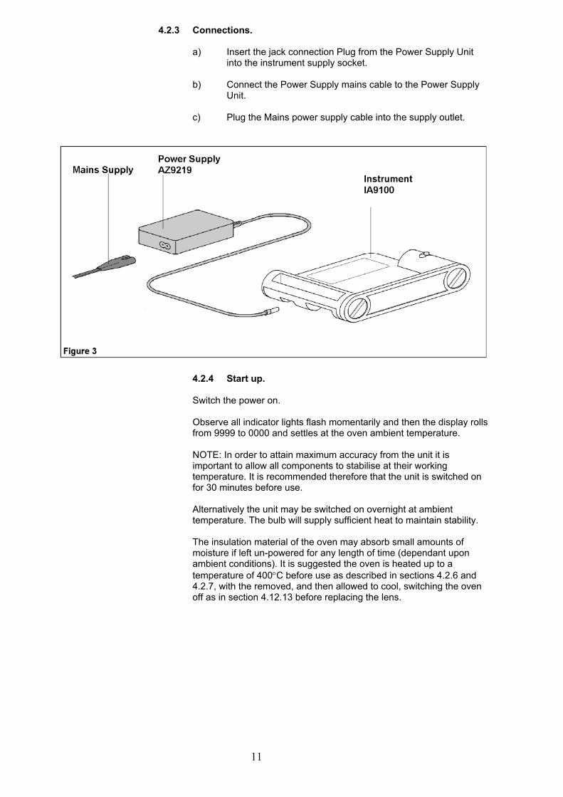
4.2.3 Connections.
a) Insert the jack connection Plug from the Power Supply Unit into the instrument supply socket.
b) Connect the Power Supply mains cable to the Power Supply
Unit.
c) Plug the Mains power supply cable into the supply outlet.
4.2.4 Start up. Switch the power on. Observe all indicator lights flash momentarily and then the display rolls from 9999 to 0000 and settles at the oven ambient temperature. NOTE: In order to attain maximum accuracy from the unit it is important to allow all components to stabilise at their working temperature. It is recommended therefore that the unit is switched on for 30 minutes before use. Alternatively the unit may be switched on overnight at ambient temperature. The bulb will supply sufficient heat to maintain stability. The insulation material of the oven may absorb small amounts of moisture if left un-powered for any length of time (dependant upon ambient conditions). It is suggested the oven is heated up to a temperature of 400"C before use as described in sections 4.2.6 and 4.2.7, with the removed, and then allowed to cool, switching the oven off as in section 4.12.13 before replacing the lens.
12
4.2.5 Prepare a Sample Up to three samples may be accommodated in the tube guide. To prepare a sample proceed as follows: Break a new capillary tube in half and insert the powdered sample in the tube. The quantity should be such that the height dose no exceed 1mm. Locate the sample in the tube guide. It is recommended that three tubes are inserted even if each tube dose not contain a sample.
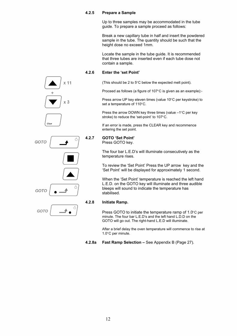
4.2.6 Enter the ‘set Point’ (This should be 2 to 5"C below the expected melt point). Proceed as follows (a figure of 107"C is given as an example):- Press arrow UP key eleven times (value 10"C per keystroke) to set a temperature of 110"C. Press the arrow DOWN key three times (value –1"C per key stroke) to reduce the ‘set-point’ to 107"C. If an error is made, press the CLEAR key and recommence entering the set point.
4.2.7 GOTO ‘Set Point’ Press GOTO key. The four bar L.E.D’s will illuminate consecutively as the temperature rises. To review the ‘Set Point’ Press the UP arrow key and the ‘Set Point’ will be displayed for approximately 1 second. When the ‘Set Point’ temperature is reached the left hand L.E.D. on the GOTO key will illuminate and three audible bleeps will sound to indicate the temperature has stabilised.
4.2.8 Initiate Ramp. Press GOTO to initiate the temperature ramp of 1.0"C per minute. The four bar L.E.D’s and the left hand L.D.D on the GOTO will go out. The right-hand L.E.D will illuminate. After a brief delay the oven temperature will commence to rise at 1.0"C per minute.
4.2.8a Fast Ramp Selection – See Appendix B (Page 27).
13
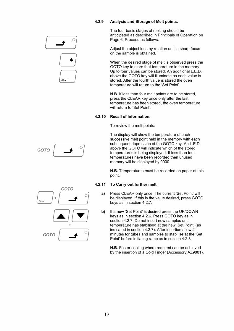
4.2.9 Analysis and Storage of Melt points. The four basic stages of melting should be anticipated as described in Principals of Operation on Page 6. Proceed as follows: Adjust the object lens by rotation until a sharp focus on the sample is obtained. When the desired stage of melt is observed press the GOTO key to store that temperature in the memory. Up to four values can be stored. An additional L.E.D. above the GOTO key will illuminate as each value is stored. After the fourth value is stored the oven temperature will return to the ‘Set Point’. N.B. If less than four melt points are to be stored, press the CLEAR key once only after the last temperature has been stored, the oven temperature will return to ‘Set Point’.
4.2.10 Recall of Information. To review the melt points: The display will show the temperature of each successive melt point held in the memory with each subsequent depression of the GOTO key. An L.E.D. above the GOTO will indicate which of the stored temperatures is being displayed. If less than four temperatures have been recorded then unused memory will be displayed by 0000. N.B. Temperatures must be recorded on paper at this point.
4.2.11 a) b)
To Carry out further melt Press CLEAR only once. The current ‘Set Point’ will be displayed. If this is the value desired, press GOTO keys as in section 4.2.7. If a new ‘Set Point’ is desired press the UP/DOWN keys as in section 4.2.6. Press GOTO key as in section 4.2.7. Do not insert new samples until temperature has stabilised at the new ‘Set Point’ (as indicated in section 4.2.7). After insertion allow 2 minutes for tubes and samples to stabilise at the ‘Set Point’ before initiating ramp as in section 4.2.8. N.B. Faster cooling where required can be achieved by the insertion of a Cold Finger (Accessory AZ9001).
14
4.2.12 1. 2. 2a. 3. 4.
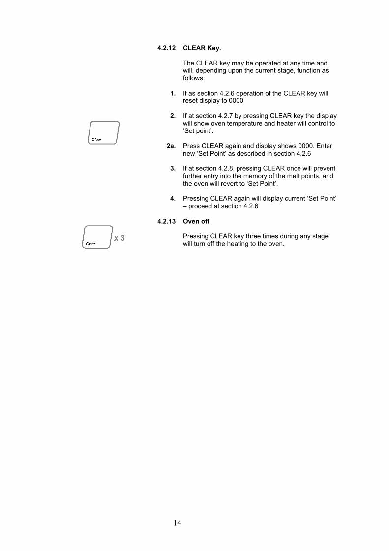
CLEAR Key. The CLEAR key may be operated at any time and will, depending upon the current stage, function as follows: If as section 4.2.6 operation of the CLEAR key will reset display to 0000 If at section 4.2.7 by pressing CLEAR key the display will show oven temperature and heater will control to ’Set point’. Press CLEAR again and display shows 0000. Enter new ‘Set Point’ as described in section 4.2.6 If at section 4.2.8, pressing CLEAR once will prevent further entry into the memory of the melt points, and the oven will revert to ‘Set Point’. Pressing CLEAR again will display current ‘Set Point’ – proceed at section 4.2.6
4.2.13 Oven off Pressing CLEAR key three times during any stage will turn off the heating to the oven.
15
Upon receipt of the instrument proceed consecutively as follows:- 4.2.1 Power Supply.
The power supply supplied with your new IA 9100 supports all A.C. Mains supply voltages within the range of 100V to 240V inclusive at 50-60Hz. Do not use the power supply with a D.C. supply voltage or in conjunction with any type of voltage regulation equipment. Do not use with a mains supply supplying power at a different frequency other than that stated.
4.2.2 Set-Up
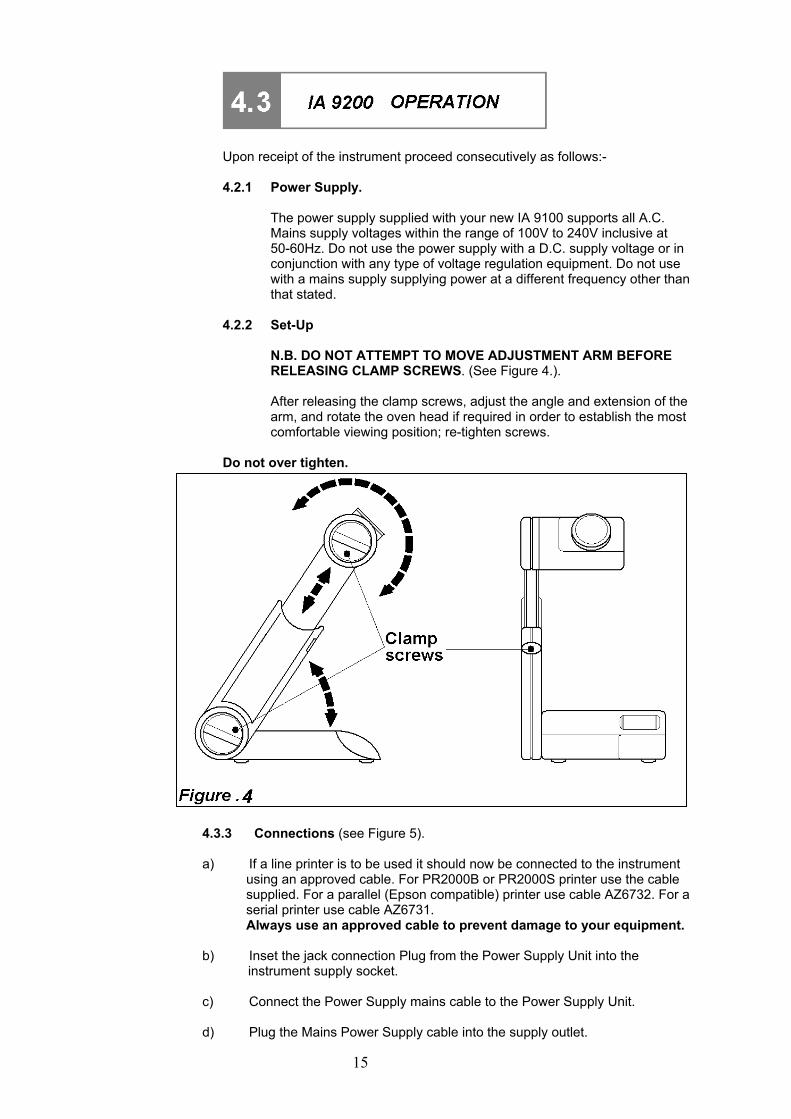
N.B. DO NOT ATTEMPT TO MOVE ADJUSTMENT ARM BEFORE RELEASING CLAMP SCREWS. (See Figure 4.). After releasing the clamp screws, adjust the angle and extension of the arm, and rotate the oven head if required in order to establish the most comfortable viewing position; re-tighten screws.
Do not over tighten.
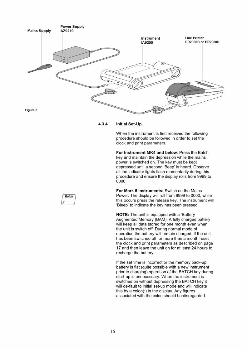
4.3.3 Connections (see Figure 5).
a) If a line printer is to be used it should now be connected to the instrument using an approved cable. For PR2000B or PR2000S printer use the cable supplied. For a parallel (Epson compatible) printer use cable AZ6732. For a serial printer use cable AZ6731. Always use an approved cable to prevent damage to your equipment.
b) Inset the jack connection Plug from the Power Supply Unit into the
instrument supply socket.
c) Connect the Power Supply mains cable to the Power Supply Unit.
d) Plug the Mains Power Supply cable into the supply outlet.
16
4.3.4 Initial Set-Up. When the instrument is first received the following
procedure should be followed in order to set the clock and print parameters.
For Instrument MK4 and below: Press the Batch
key and maintain the depression while the mains power is switched on. The key must be kept depressed until a second ‘Beep’ is heard. Observe all the indicator lights flash momentarily during this procedure and ensure the display rolls from 9999 to 0000.
For Mark 5 Instruments: Switch on the Mains Power. The display will roll from 9999 to 0000, while this occurs press the release key. The instrument will ‘Bleep’ to indicate the key has been pressed.
NOTE: The unit is equipped with a ‘Battery
Augmented Memory (BAM). A fully charged battery will keep all data stored for one month even when the unit is switch off. During normal mode of operation the battery will remain charged. If the unit has been switched off for more than a month reset the clock and print parameters as described on page 17 and then leave the unit on for at least 24 hours to recharge the battery.
If the set time is incorrect or the memory back-up
battery is flat (quite possible with a new instrument prior to charging) operation of the BATCH key during start-up is unnecessary. When the instrument is switched on without depressing the BATCH key it will de-fault to initial set-up mode and will indicate this by a colon(:) in the display. Any figures associated with the colon should be disregarded.
17
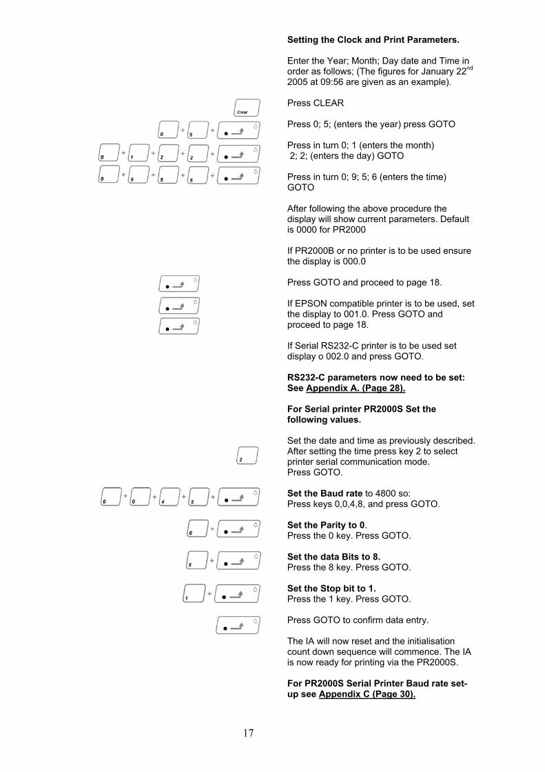
Setting the Clock and Print Parameters. Enter the Year; Month; Day date and Time in order as follows; (The figures for January 22nd 2005 at 09:56 are given as an example). Press CLEAR Press 0; 5; (enters the year) press GOTO Press in turn 0; 1 (enters the month) 2; 2; (enters the day) GOTO Press in turn 0; 9; 5; 6 (enters the time) GOTO After following the above procedure the display will show current parameters. Default is 0000 for PR2000 If PR2000B or no printer is to be used ensure the display is 000.0 Press GOTO and proceed to page 18. If EPSON compatible printer is to be used, set the display to 001.0. Press GOTO and proceed to page 18. If Serial RS232-C printer is to be used set display o 002.0 and press GOTO. RS232-C parameters now need to be set: See Appendix A. (Page 28).
For Serial printer PR2000S Set the following values. Set the date and time as previously described. After setting the time press key 2 to select printer serial communication mode. Press GOTO. Set the Baud rate to 4800 so: Press keys 0,0,4,8, and press GOTO. Set the Parity to 0. Press the 0 key. Press GOTO. Set the data Bits to 8. Press the 8 key. Press GOTO. Set the Stop bit to 1. Press the 1 key. Press GOTO. Press GOTO to confirm data entry. The IA will now reset and the initialisation count down sequence will commence. The IA is now ready for printing via the PR2000S. For PR2000S Serial Printer Baud rate set-up see Appendix C (Page 30).
18
4.3.5 Normal Start-up
Switch the power on.
Observe all indicator lights flash momentarily and then the display rolls from 9999 to 0000 and settles at the oven ambient temperature.
NOTE: In order to attain maximum accuracy from the unit it is important to allow all components to stabilise at their working temperature. It is recommended therefore that the unit is switched on for 30 minutes before use.
Alternatively the unit may be switched on overnight at ambient temperature. The bulb will supply sufficient heat to maintain stability.
The insulation material of the oven may absorb small amounts of moisture if left un-powered for any length of time (dependant upon ambient conditions). It is suggested the oven is heated up to a temperature of 300"C before use as described in sections 4.3.7 and 4.3.8, with the removed, and then allowed to cool, switching the oven off as in section 4.3.14 before replacing the lens.
4.3.6 Prepare a Sample Up to three samples may be
accommodated in the tube guide. To prepare a sample proceed as follows: Break a new capillary tube in half and insert the powdered sample in the tube. The quantity should be such that the height dose no exceed 1mm. Locate the sample in the tube guide. It is recommended that three tubes are inserted even if each tube dose not contain a sample.
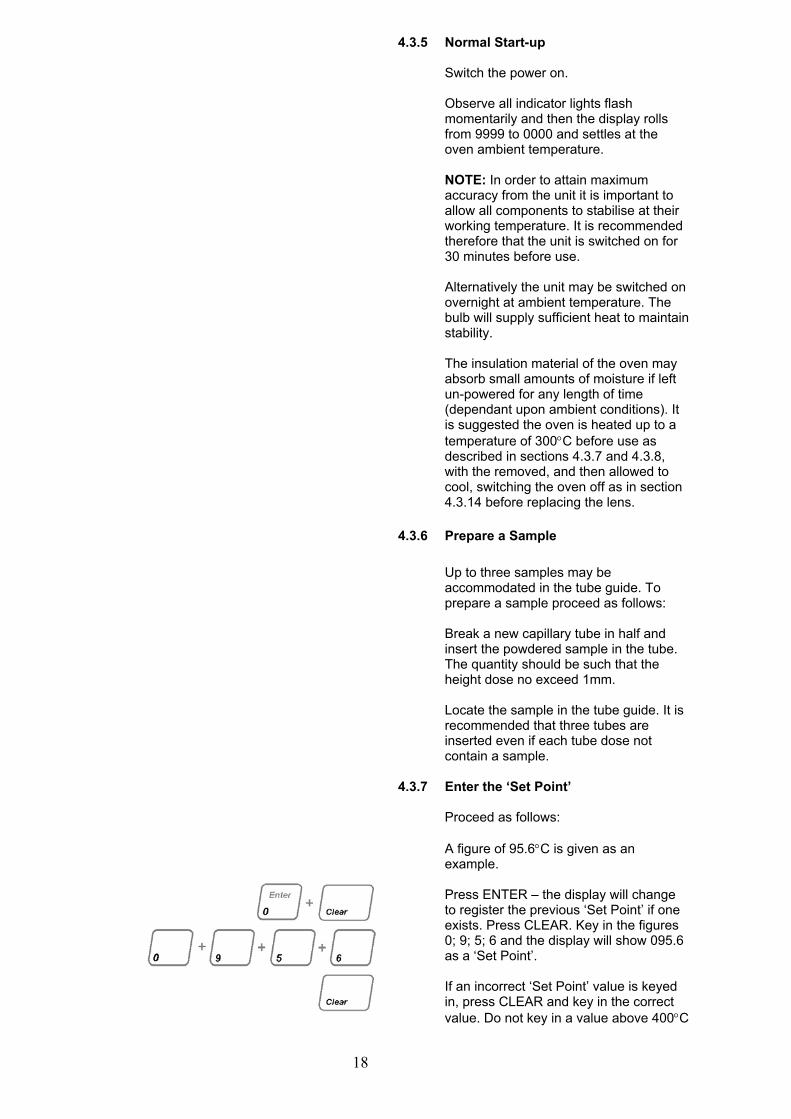
4.3.7 Enter the ‘Set Point’
Proceed as follows: A figure of 95.6"C is given as an example. Press ENTER – the display will change to register the previous ‘Set Point’ if one exists. Press CLEAR. Key in the figures 0; 9; 5; 6 and the display will show 095.6 as a ‘Set Point’. If an incorrect ‘Set Point’ value is keyed in, press CLEAR and key in the correct value. Do not key in a value above 400"C
19
4.3.8 GOTO ‘Set-Point’
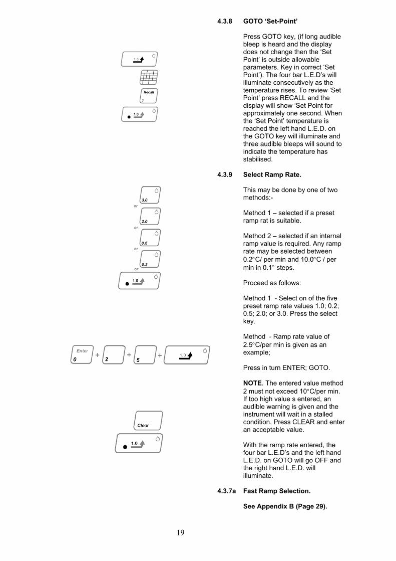
Press GOTO key, (if long audible bleep is heard and the display does not change then the ‘Set Point’ is outside allowable parameters. Key in correct ‘Set Point’). The four bar L.E.D’s will illuminate consecutively as the temperature rises. To review ‘Set Point’ press RECALL and the display will show ‘Set Point for approximately one second. When the ‘Set Point’ temperature is reached the left hand L.E.D. on the GOTO key will illuminate and three audible bleeps will sound to indicate the temperature has stabilised.
4.3.9 Select Ramp Rate.
This may be done by one of two methods:- Method 1 – selected if a preset ramp rat is suitable. Method 2 – selected if an internal ramp value is required. Any ramp rate may be selected between 0.2"C/ per min and 10.0"C / per min in 0.1" steps. Proceed as follows: Method 1 - Select on of the five preset ramp rate values 1.0; 0.2; 0.5; 2.0; or 3.0. Press the select key. Method - Ramp rate value of 2.5"C/per min is given as an example; Press in turn ENTER; GOTO. NOTE. The entered value method 2 must not exceed 10"C/per min. If too high value s entered, an audible warning is given and the instrument will wait in a stalled condition. Press CLEAR and enter an acceptable value. With the ramp rate entered, the four bar L.E.D’s and the left hand L.E.D. on GOTO will go OFF and the right hand L.E.D. will illuminate.
4.3.7a Fast Ramp Selection. See Appendix B (Page 29).
20
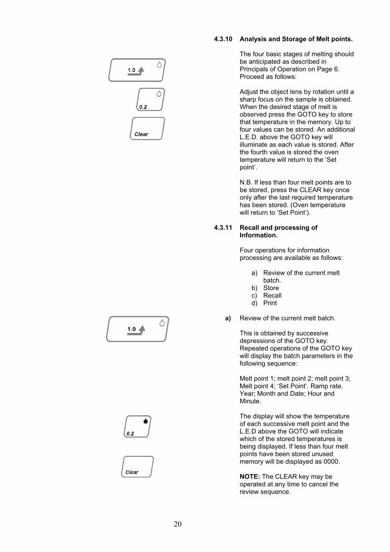
4.3.10 Analysis and Storage of Melt points. The four basic stages of melting should be anticipated as described in Principals of Operation on Page 6. Proceed as follows: Adjust the object lens by rotation until a sharp focus on the sample is obtained. When the desired stage of melt is observed press the GOTO key to store that temperature in the memory. Up to four values can be stored. An additional L.E.D. above the GOTO key will illuminate as each value is stored. After the fourth value is stored the oven temperature will return to the ‘Set point’. N.B. If less than four melt points are to be stored, press the CLEAR key once only after the last required temperature has been stored. (Oven temperature will return to ‘Set Point’).
4.3.11 a)
Recall and processing of Information. Four operations for information processing are available as follows:
a) Review of the current melt batch.
b) Store c) Recall d) Print
Review of the current melt batch. This is obtained by successive depressions of the GOTO key. Repeated operations of the GOTO key will display the batch parameters in the following sequence: Melt point 1; melt point 2; melt point 3; Melt point 4; ‘Set Point’. Ramp rate. Year; Month and Date; Hour and Minute. The display will show the temperature of each successive melt point and the L.E.D above the GOTO will indicate which of the stored temperatures is being displayed. If less than four melt points have been stored unused memory will be displayed as 0000. NOTE: The CLEAR key may be operated at any time to cancel the review sequence.
21
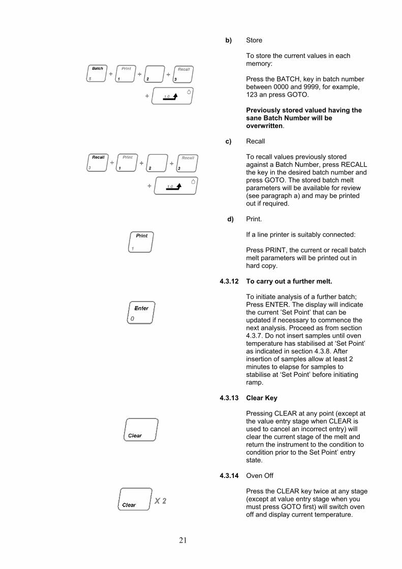
b)
Store To store the current values in each memory: Press the BATCH, key in batch number between 0000 and 9999, for example, 123 an press GOTO. Previously stored valued having the sane Batch Number will be overwritten.
c) Recall To recall values previously stored against a Batch Number, press RECALL the key in the desired batch number and press GOTO. The stored batch melt parameters will be available for review (see paragraph a) and may be printed out if required.
d) Print. If a line printer is suitably connected: Press PRINT, the current or recall batch melt parameters will be printed out in hard copy.
4.3.12 To carry out a further melt.
To initiate analysis of a further batch; Press ENTER. The display will indicate the current ’Set Point’ that can be updated if necessary to commence the next analysis. Proceed as from section 4.3.7. Do not insert samples until oven temperature has stabilised at ‘Set Point’ as indicated in section 4.3.8. After insertion of samples allow at least 2 minutes to elapse for samples to stabilise at ‘Set Point’ before initiating ramp.
4.3.13 Clear Key
Pressing CLEAR at any point (except at the value entry stage when CLEAR is used to cancel an incorrect entry) will clear the current stage of the melt and return the instrument to the condition to condition prior to the Set Point’ entry state.
4.3.14 Oven Off
Press the CLEAR key twice at any stage (except at value entry stage when you must press GOTO first) will switch oven off and display current temperature.
22
The IA9300 provides a range of facilities as the 9200 with the following exceptions:
! Only one pre-programmed ramp rate is available i.e. 1.0"C/per min. ! Six melting points may be stored in the resident memory per batch. ! Three additional LED indicators are installed in the head to facilitate
ease of assignment of recorded melt points to particular capillaries. ! The number of batches that can be recorded in the memory is reduced
to 500.
4.4.1 Mode of Operation.
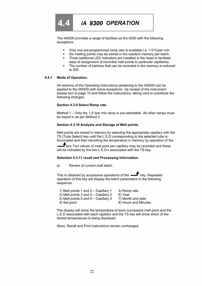
All sections of the Operating Instructions pertaining to the IA9200 can be applied to the IA9300 with some exceptions. Up receipt of the instrument please turn to page 15 and follow the instructions, taking care to substitute the following changes. Section 4.3.9 Select Ramp rate. Method 1 – Only the 1.0"/per min ramp is pre-selectable. All other ramps must be keyed in as per Method 2. Section 4.3.10 Analysis and Storage of Melt points. Melt points are stored in memory by selecting the appropriate capillary with the TS (Tube Select) key until the L.E.D corresponding to the selected tube is illuminated and then recording the temperature in memory by operation of the
key Two values of melt point per capillary may be recorded and these will be indicated by the two L.E.D’s associated with the TS key. Selection 4.3.11 recall and Processing Information. a) Review of current malt batch.
This is obtained by successive operations of the key. Repeated operation of this key will display the batch parameters in the following sequence.
1) Melt points 1 and 2 – Capillary 1 5) Ramp rate. 2) Melt points 3 and 4 – Capillary 2 6) Year 3) Melt points 5 and 6 – Capillary 3 7) Month and date 4) Set point 8) Hours and Minutes.
The display will show the temperature of each successive melt point and the L.E.D associated with each capillary and the TS key will show which of the stored temperatures is being displayed. Store, Recall and Print instructions remain unchanged.
23
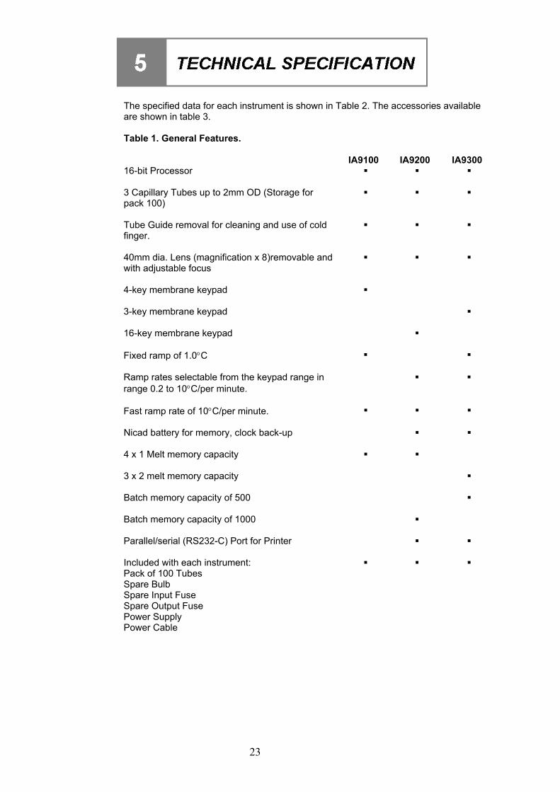
The specified data for each instrument is shown in Table 2. The accessories available are shown in table 3. Table 1. General Features. IA9100 IA9200 IA9300 16-bit Processor ! ! ! 3 Capillary Tubes up to 2mm OD (Storage for pack 100)
! ! !
Tube Guide removal for cleaning and use of cold finger.
! ! !
40mm dia. Lens (magnification x 8)removable and with adjustable focus
! ! !
4-key membrane keypad ! 3-key membrane keypad ! 16-key membrane keypad ! Fixed ramp of 1.0"C ! ! Ramp rates selectable from the keypad range in range 0.2 to 10"C/per minute.
! !
Fast ramp rate of 10"C/per minute. ! ! ! Nicad battery for memory, clock back-up ! ! 4 x 1 Melt memory capacity ! ! 3 x 2 melt memory capacity ! Batch memory capacity of 500 ! Batch memory capacity of 1000 ! Parallel/serial (RS232-C) Port for Printer ! ! Included with each instrument: ! ! ! Pack of 100 Tubes Spare Bulb Spare Input Fuse Spare Output Fuse Power Supply Power Cable
24
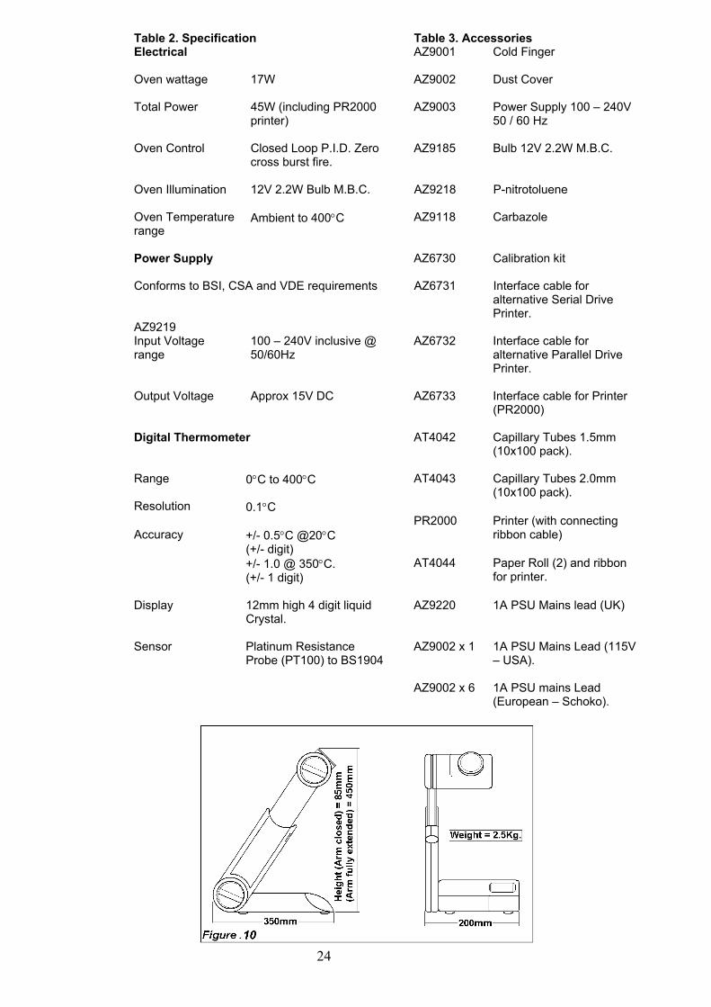
Table 2. Specification Table 3. Accessories Electrical AZ9001 Cold Finger Oven wattage 17W AZ9002 Dust Cover Total Power 45W (including PR2000
printer) AZ9003 Power Supply 100 – 240V
50 / 60 Hz Oven Control Closed Loop P.I.D. Zero
cross burst fire. AZ9185 Bulb 12V 2.2W M.B.C.
Oven Illumination 12V 2.2W Bulb M.B.C. AZ9218 P-nitrotoluene Oven Temperature range
Ambient to 400"C AZ9118 Carbazole
Power Supply AZ6730 Calibration kit Conforms to BSI, CSA and VDE requirements AZ6731 Interface cable for
alternative Serial Drive Printer.
AZ9219 Input Voltage range
100 – 240V inclusive @ 50/60Hz
AZ6732 Interface cable for alternative Parallel Drive Printer.
Output Voltage Approx 15V DC AZ6733 Interface cable for Printer
(PR2000) Digital Thermometer AT4042 Capillary Tubes 1.5mm
(10x100 pack). Range 0"C to 400"C AT4043 Capillary Tubes 2.0mm
(10x100 pack). Resolution 0.1"C Accuracy
+/- 0.5"C @20"C
PR2000 Printer (with connecting ribbon cable)
(+/- digit) +/- 1.0 @ 350"C.
(+/- 1 digit) AT4044 Paper Roll (2) and ribbon
for printer. Display 12mm high 4 digit liquid
Crystal. AZ9220 1A PSU Mains lead (UK)
Sensor Platinum Resistance
Probe (PT100) to BS1904 AZ9002 x 1 1A PSU Mains Lead (115V
– USA). AZ9002 x 6 1A PSU mains Lead
(European – Schoko).
25
This equipment is classified as Class II (Ref. IEC 536) with respect to protection against electric shock. WARNING
* Unplug equipment from mains supply before undertaking any maintenance tasks.
* Maintenance should only be carried out by a competent Electrician under the direction of the Responsible body
With proper care and operation the equipment should give reliable service. Contamination, or general misuse will however reduce the effective life of the product and may cause a hazard. Maintenance for the equipment should include:
- Periodic electrical safety testing of the power supply unit (an annual test is recommended as a minimum requirement).
- Regular inspection for damage with particular reference to mains leads and lug / sockets.
Preventive maintenance for the equipment should include keeping the unit clean and protecting it from spillage, contamination or corrosive environments. If the equipment has been exposed to spillage or contamination, the Responsible Body is responsible for carrying out appropriate decontamination if hazardous materials have been spilt on or inside the equipment. Decontamination should only be undertaken under the control of the Responsible Body with due recommended of possible hazards that may ensue. Before using any cleaning or decontamination method, except those recommended in the Operating Instructions, the Responsible Body should check with the manufacture that the proposed method will not damage the equipment.
* This equipment contains insulation made from Refractory ceramic Fibres. EU Directive EEC/67/548 classifies this material a class 2 carcinogenic, a risk if inhaled or digested. In normal use there will be no contact with this material, but care should be taken when servicing or disposing of the equipment. A code of Practice and Material Safety Data Sheet are available on request, please contact your supplier.
AVERTISSEMENT.
* Coupez I’alimention principale de I’ appareil et laissez-le refroidir avant d’en effectuer I’entretien.
* Sous la direction de I’autorité responsible, ne confiez I’entretien qu’à un èlectricien competent. * N’UTILISEZ AUCUN SOLVANT POUR NETTOYER L’UNE OU L’AUTRE DES PIÈCES DE
L’APPAREIL.
* Si I’èquipmet est exposè à un dèversement ou à une contamination, il revient à làutoritè responsible d’effecture la decontamination approprièe, que le produit dangerux ait ètè renversè à I’intèrieur ou à I’extèrieur de I’appareil. A decontamination ne doit ètre enterprise que sous la serveillance de l’autoritè responsible et en parfaite connaissance des risques èventuels. Avant de recourir à toute mèthode de nettoyage ou de decontamination, I’autoritè responsible devrait s’assurer auprès du fabfricant que ladite mèthode ne risqué pas d’endommager I’appareil.
* N’effectuez le sèchage du four qu’après vous être assure qu’aucune substance à faible point d’èclair n’est present, compte tenu d’une temperature de sèchage de 60 à 80ºC.
26
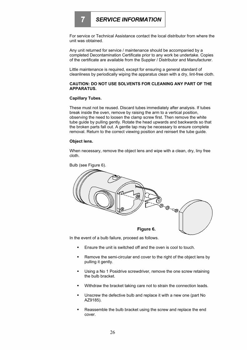
For service or Technical Assistance contact the local distributor from where the unit was obtained. Any unit returned for service / maintenance should be accompanied by a completed Decontamination Certificate prior to any work be undertake. Copies of the certificate are available from the Suppler / Distributor and Manufacturer. Little maintenance is required, except for ensuring a general standard of cleanliness by periodically wiping the apparatus clean with a dry, lint-free cloth. CAUTION: DO NOT USE SOLVENTS FOR CLEANING ANY PART OF THE APPARATUS. Capillary Tubes. These must not be reused. Discard tubes immediately after analysis. If tubes break inside the oven, remove by raising the arm to a vertical position, observing the need to loosen the clamp screw first. Then remove the white tube guide by pulling gently. Rotate the head upwards and backwards so that the broken parts fall out. A gentle tap may be necessary to ensure complete removal. Return to the correct viewing position and reinsert the tube guide. Object lens. When necessary, remove the object lens and wipe with a clean, dry, liny free cloth. Bulb (see Figure 6).
In the event of a bulb failure, proceed as follows.
! Ensure the unit is switched off and the oven is cool to touch. ! Remove the semi-circular end cover to the right of the object lens by
pulling it gently.
! Using a No 1 Posidrive screwdriver, remove the one screw retaining the bulb bracket.
! Withdraw the bracket taking care not to strain the connection leads. ! Unscrew the defective bulb and replace it with a new one (part No
AZ9185).
! Reassemble the bulb bracket using the screw and replace the end cover.
27
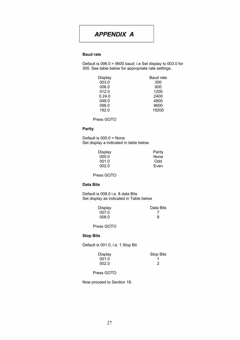
Baud rate Default is 096.0 = 9600 baud; i.e Set display to 003.0 for 300. See table below for appropriate rate settings.
Display Baud rate 003.0 300 006.0 600 012.0 1200 0.24.0 2400 048.0 4800 096.0 9600 192.0 19200
Press GOTO
Parity
Default is 000.0 = None Set display a indicated in table below.
Display Parity 000.0 None 001.0 Odd 002.0 Even
Press GOTO
Data Bits Default is 008.0 i.e. 8 data Bits Set display as indicated in Table below
Display Data Bits 007.0 7 008.0 8
Press GOTO
Stop Bits Default is 001.0, i.e. 1 Stop Bit
Display Stop Bits 001.0 1 002.0 2
Press GOTO
Now proceed to Section 18.
28
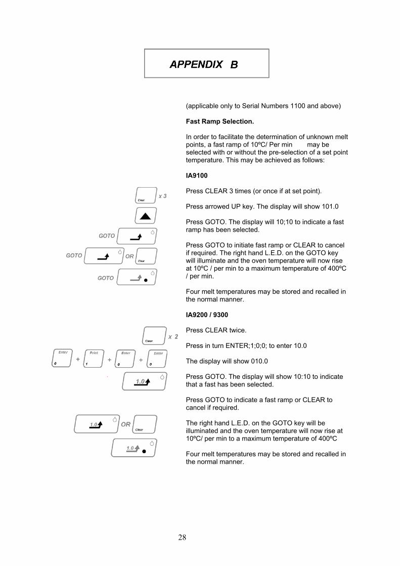
(applicable only to Serial Numbers 1100 and above)
Fast Ramp Selection.
In order to facilitate the determination of unknown melt points, a fast ramp of 10ºC/ Per min may be selected with or without the pre-selection of a set point temperature. This may be achieved as follows: IA9100 Press CLEAR 3 times (or once if at set point). Press arrowed UP key. The display will show 101.0 Press GOTO. The display will 10;10 to indicate a fast ramp has been selected. Press GOTO to initiate fast ramp or CLEAR to cancel if required. The right hand L.E.D. on the GOTO key will illuminate and the oven temperature will now rise at 10ºC / per min to a maximum temperature of 400ºC / per min. Four melt temperatures may be stored and recalled in the normal manner.
IA9200 / 9300
Press CLEAR twice. Press in turn ENTER;1;0;0; to enter 10.0 The display will show 010.0 Press GOTO. The display will show 10:10 to indicate that a fast has been selected. Press GOTO to indicate a fast ramp or CLEAR to cancel if required. The right hand L.E.D. on the GOTO key will be illuminated and the oven temperature will now rise at 10ºC/ per min to a maximum temperature of 400ºC Four melt temperatures may be stored and recalled in the normal manner.
29
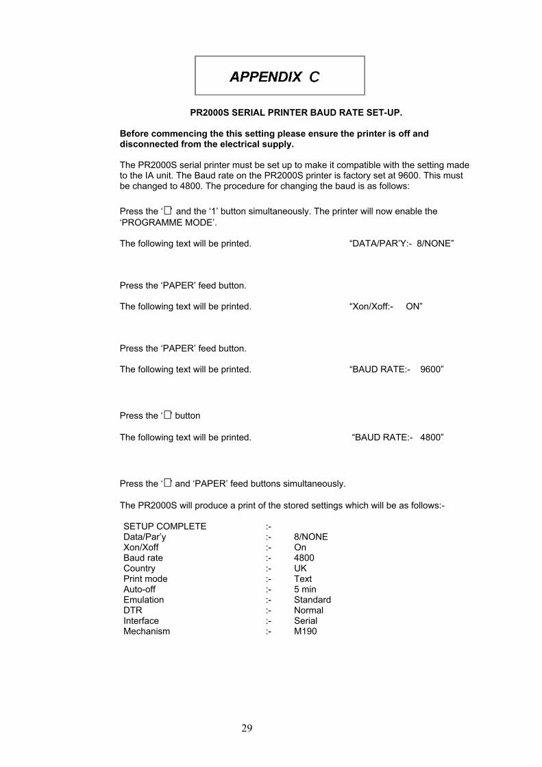
PR2000S SERIAL PRINTER BAUD RATE SET-UP.
Before commencing the this setting please ensure the printer is off and disconnected from the electrical supply. The PR2000S serial printer must be set up to make it compatible with the setting made to the IA unit. The Baud rate on the PR2000S printer is factory set at 9600. This must be changed to 4800. The procedure for changing the baud is as follows: Press the ‘�’ and the ‘1’ button simultaneously. The printer will now enable the ‘PROGRAMME MODE’. The following text will be printed. “DATA/PAR’Y:- 8/NONE” Press the ‘PAPER’ feed button. The following text will be printed. “Xon/Xoff:- ON” Press the ‘PAPER’ feed button. The following text will be printed. “BAUD RATE:- 9600” Press the ‘�’ button The following text will be printed. “BAUD RATE:- 4800” Press the ‘�’ and ‘PAPER’ feed buttons simultaneously. The PR2000S will produce a print of the stored settings which will be as follows:- SETUP COMPLETE :- Data/Par’y :- 8/NONE Xon/Xoff :- On Baud rate :- 4800 Country :- UK Print mode :- Text Auto-off :- 5 min Emulation :- Standard DTR :- Normal Interface :- Serial Mechanism :- M190

30

31
32
CE marked products and associated accessories covered by this Instruction book conform to the essential requirements of the following directives:
EMC Directive. Low Voltage Directive.
A full copy of the EC Declaration / Conformity document can be obtained from the manufacture at the email address [email protected]
DISTRUBORS STAMP
For further information please contact.
Thermo Fisher Scientific. Electrothermal House. Unit12A, Purdeys Way. Purdeys Industrial Estate. Rochford, Essex. SS4 1ND Great Britain. Tel +44(0)1702 303350 Fax+44(0)1702 468731 E-Mail: [email protected]
Thermo Fisher Scientific. 2555 Kerper Boulevard PO Box 797, Dubuque, Iowa 52004-0797, USA Tel:-800 553 0039 or (563) 556-2241 Fax: (563) 589-0516 Http www.thermo.com
www.electrothermal.co.uk. www.stemcorp.co.uk
# 2008 Thermo Fisher Scientific Inc. All rights reserved.
Printed in Great Britain
Operating and safety Instruction booklet part No M6346 Issue 6.5