Embed Size (px)
Citation preview

ELEN 701 RF & Microwave Systems Engineering
Lecture 2September 27, 2006Dr. Michael ThorburnSanta Clara University

Lecture 2 – Radio Architecture and Design Considerations, Part I
• Architecture– Superheterodyne Architecture
• Configuration• RF/IF/BB Sections
– Direct Conversion Architecture• Configuration
• Functional Description of Fundamental Elements – Duplexers,LNAs,Filters, Mixers, LO Synthesizers
• Key Performance Parameters and Analyses– Frequency Planning – Spurious Analysis– Receiver Sensitivity, Linearity and Selectivity
• Analysis Techniques – Nonlinear Systems– Noise Figure
Superheterodyne Full-Duplex Architecture Configuration
Mixing incoming signal with an offset LO in a nonlinear device to generate an intermediate IF signal
Key Nonlinear device: Frequency Mixer or Frequency Converter

Major Elements and Performance Parameters
• Receiver – Sensitivity– Linearity– Selectivity
• Transmitter (next week)– Output Power– Spectrum– Modulation Accuracy

Antenna & Duplexer
Transmit Signal869-894 MHz
Receive Signal824-849 MHz
Band Pass Filter – Receive Band
Band Pass Filter – Transmit Band
Antenna

RF Front End
Receive Signal824-849 MHz
LNA is important in achieving good reception sensitivity – gain is step controlled to cope with receiver dynamic range
Bandpass Filter - High Edge to further suppress transmit; Low Edge for image rejection
UHF Synthesizer provides LO power to RF converters in RCV and TX. It also has role of channel tuning for the transceiver
Nonlinear characteristics of mixer generates spurious frequencies which must be managed
RF Amp establishes NF of Receiver

IF Section
IF Section@ IF Frequency
DeMod
IF Amp provides front end gain for IF Section
VGA establishes signal level for DeMod
BasebandSection
IF SAW Filter has high selectivity for channel filtering to separate desired from unwanted channels
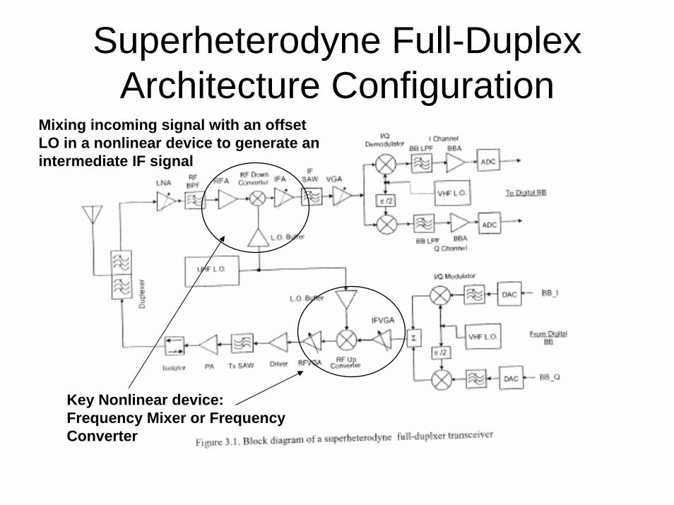
Direct Conversion Architecture Configuration

Comparison of Architectures -Partitioned by Function
• Superheterodyne– RF Section
• LNA• RF BPF• RFA
– Frequency Conversion• RF Downconverter (Mixer)• LO
– IF Section• IFA• IF SAW• VGA
– Frequency Conversion• IQ Demod
– Baseband (I & Q channels)• LPF• BBA• ADC
• Direct Conversion– RF Section
• LNA• RF BPF• RFA
– Frequency Conversion• I/Q Demod/ Downconverter• UHF Synthesizer
– Baseband (I & Q channels)• BBA• LPF• BBA• ADC

Comparison of Architectures –Partitioned by Units
• Superheterodyne– Receiver
• LNA• RF BPF• RFA• RF Mixer• LO• IFA• IF SAW
– Demod• VGA• I/Q Demodulator• BB LPF
– Baseband (I & Q channels)• BBA• ADC
• Direct Conversion– RF Section
• LNA• RF BPF
– RF Demod• RFA• I/Q Demod/ Downconverter• UHF Synthesizer• BBA• LPF
– Baseband (I & Q channels)• BBA• ADC

Next Steps: Design Process• Architecture - Functional Block Diagram• Design/Performance
– Frequency Planning• Selection of IF frequency to minimize self interference
– Spurious Analysis
– Line-up Analysis• Signal Strength (Gain/Loss) Budgets• Determine Required Gains
– Receiver Sensitivity• Minimum detectable desired signal strength to obtain a
certain BER or frame error rate (FER)• Noise Figure
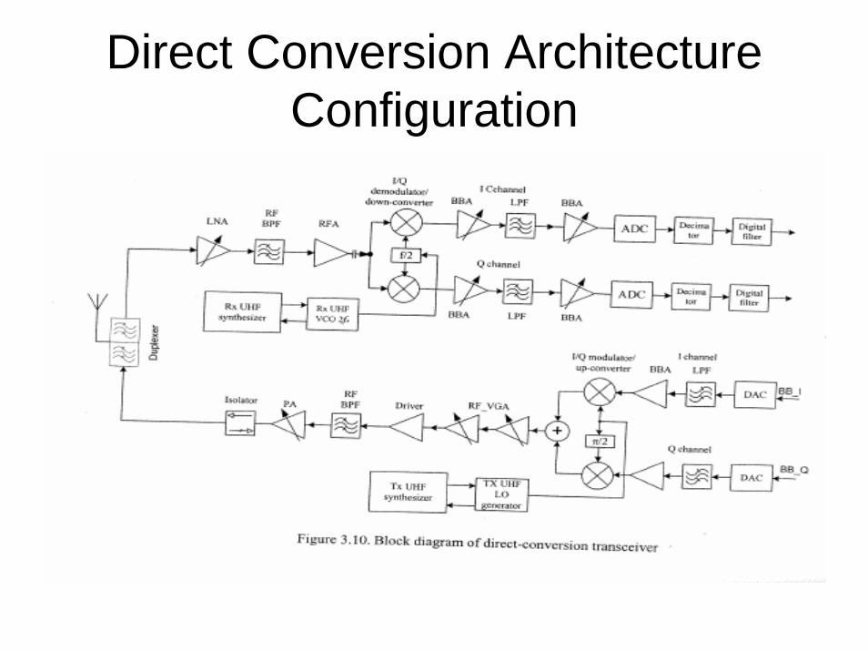
Design Process
– Receiver Linearity– Receiver Selectivity
• Characteristic of the receiver that allows it to identify the desired signal at one frequency apart from those at all other frequencies.
– Mainly determined by RF, IF and BB filters!
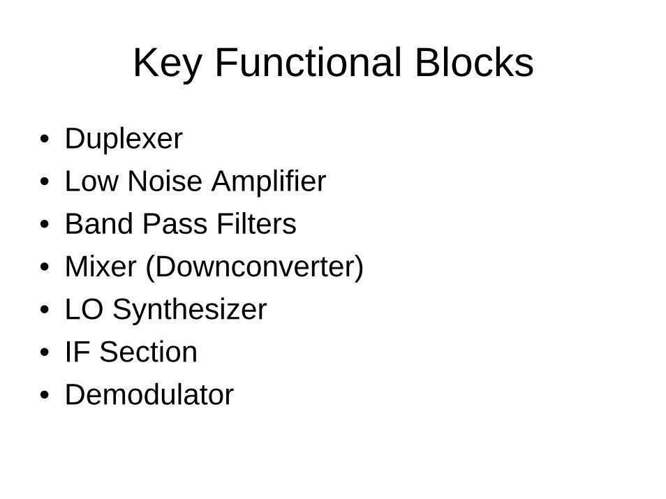
Key Functional Blocks
• Duplexer• Low Noise Amplifier• Band Pass Filters• Mixer (Downconverter)• LO Synthesizer• IF Section• Demodulator
Duplexer
• Key Functions– Connects Receive (Rx) from Transmit (Tx)
signal paths to antenna– Provides separation of power in Rx and Tx
paths – in particular providing rejection of Txin Rx path

Low Noise Amplifier (LNA)
• Key Function– First stage of signal amplification– Establishes Noise Figure (NF) of System
• Primary Factor• Receiver and Demod may degrade NF and should
be tracked– Thereby establishing Transceiver Sensitivity

RF Band Pass Filter
• Key Functions– Provides additional rejection of transmit band
(high band edge)– Provides rejection of mixer image frequencies
and other spurious signals (low band edge)
• Note: LNA is typically very broad band. Pre-LNA filtering required to protect LNA from overdrive. Pre-Receiver filtering is required to protect Receiver from other unwanted signals – Spurs (Spurious Signals)
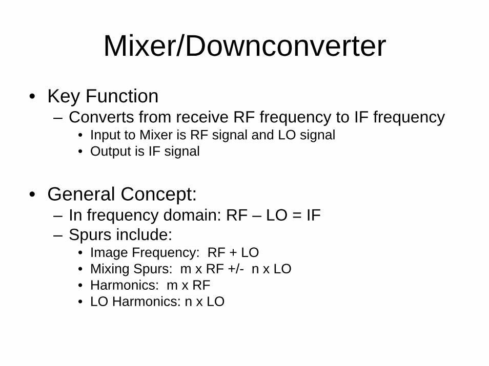
Mixer/Downconverter• Key Function
– Converts from receive RF frequency to IF frequency• Input to Mixer is RF signal and LO signal• Output is IF signal
• General Concept:– In frequency domain: RF – LO = IF– Spurs include:
• Image Frequency: RF + LO• Mixing Spurs: m x RF +/- n x LO• Harmonics: m x RF• LO Harmonics: n x LO
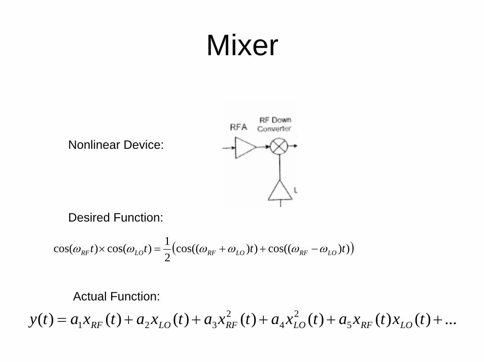
Mixer
( )))cos(())cos((21)cos()cos( tttt LORFLORFLORF ωωωωωω −++=×
Nonlinear Device:
Desired Function:
Actual Function:
...)()()()()()()( 52
42
321 +++++= txtxatxatxatxatxaty LORFLORFLORF

LO Synthsizer
• Key Function:– Provides LO– Via LO selection (Superheterodyne) – selects
channels
IF Section
• Key Function:– Establishes power level and filtering for
Demod and Baseband Section
Demodulator
• Demodulates IF signal in preparation of Analog-to-Digital Converter

Receiver Sensitivity
• Figure of Merit is G/T• Antenna Gain - Gives G• T has an Antenna Component and a Transceiver
Component
Feeder Input Loss,1/LF
+
Equivalent InputNoise Temp, TF
Feeder Network
TF
Noise-freesystem, Gain GRX
+
Equivalent InputNoise Temp, TRx
Receiver
TRx
Antenna NoiseTemp TA
T1 = TA + TF (LF -1) + [ TRx / (1/LF) ]
= TA + TF (LF -1) + [TRx * LF ]
T2T1
Note: LF > 1
T2 = TA / LF+ TF (LF -1) / LF + TRx
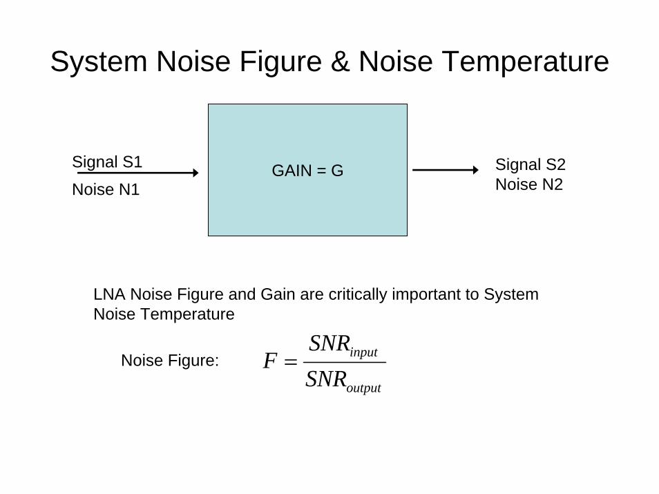
System Noise Figure & Noise Temperature
LNA Noise Figure and Gain are critically important to System Noise Temperature
output
input
SNRSNR
F =Noise Figure:
GAIN = GSignal S1
Noise N1Signal S2Noise N2

System Noise Figure
GAIN = G
Signal S1
Noise N1
Self Noise No
Signal G x S1Noise G x (N1+No)
1
011N
NNF ++=

System Noise Figure and Noise Temperature
Feeder Input Loss,1/LF
+
Equivalent InputNoise Temp, TF
Feeder Network
TF
Noise-freesystem, Gain GRX
+
Equivalent InputNoise Temp, TRx
Receiver
TRx
Antenna NoiseTemp TA
T1 = TA + TF (LF -1) + [ TRx / (1/LF) ]
= TA + TF (LF -1) + [TRx * LF ]
T2T1
Note: LF > 1
T2 = TA / LF+ TF (LF -1) / LF + TRx
LNA Noise Figure and Gain are critically important to System Noise Temperature ( ) 01 TFTe −=

Trades between Noise Figure and Linearity
• Best Noise Figure– Lump Gain in Front End
• Best Linearity– Distribute Gain Evenly

Cellular Spectrum Example
• Uplink (Forward): 824 – 849 MHz• Downlink (Return): 869 – 894 MHz
• Band Separation = 20 MHz (=869-849)• Channel Spacing = 30 kHz (CDMA)
Uplink Channel Downlink Channel869 MHz 894 MHz849 MHz824 MHz
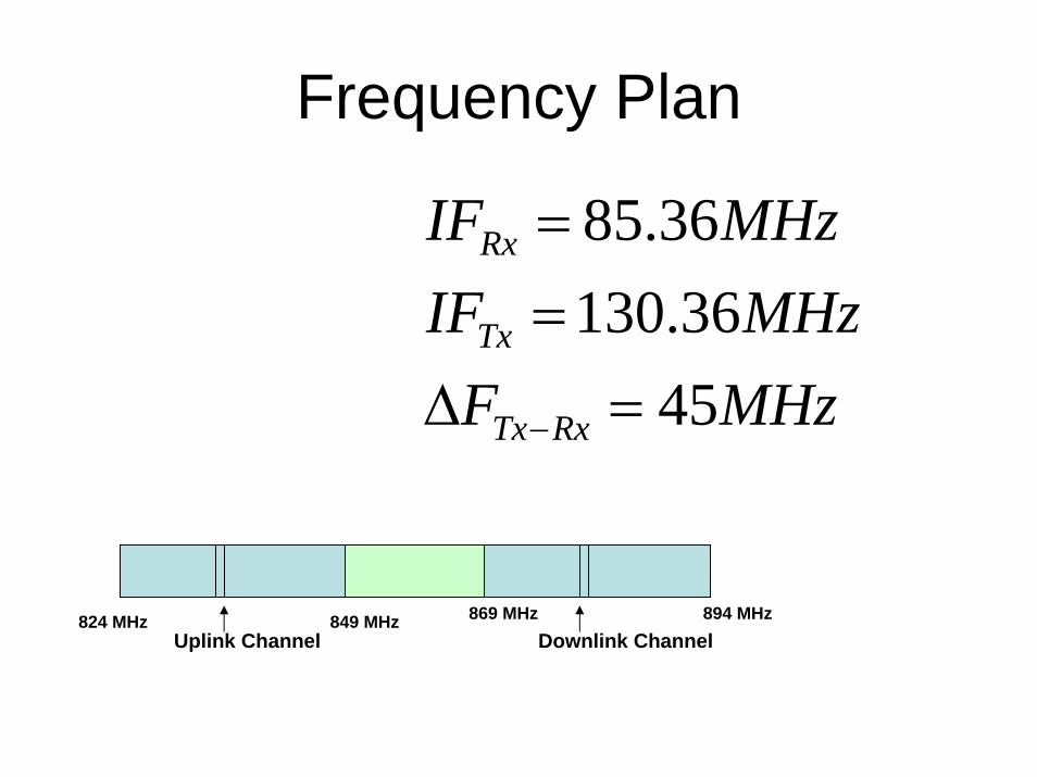
Frequency Plan
Uplink Channel Downlink Channel869 MHz 894 MHz849 MHz824 MHz
MHzFMHzIF
MHzIF
RxTx
Tx
Rx
4536.130
36.85
=Δ==
−