Embed Size (px)
Citation preview

ENE 325ENE 325Electromagnetic Electromagnetic Fields and WavesFields and Waves
Lecture 6 Lecture 6 Capacitance and Capacitance and MagnetostaticsMagnetostatics
1

Review (1)Review (1)
Conductor and boundary conditions tangential electric field, Et , 0= for equipotenti
al surface. normal electric flux density Dn = s .
Dielectric macroscopic electric dipoles and bound charges Polarization is dipole moment per unit volume,
electric flux density in dielectric medium,
0 1
1lim
n v
iv i
P pv
��������������
0D E P ������������������������������������������
2

Review (2)Review (2)
Dielectric and boundary conditions tangentialel ect r i c fi el d, Et1 = Et2 normal electric flux density .
1 221 ( ) Sa D D
����������������������������
3
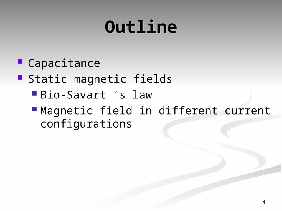
OutlineOutline
Capacitance Static magnetic fields
Bio-Savart ‘s law Magnetic field in different current
configurations
4
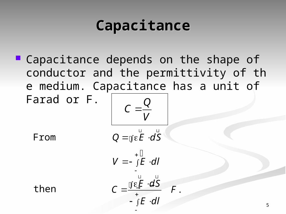
CapacitanceCapacitance
Capacitancedependson t he shape of conduct or and t he permi ttivity of the medium. Capacitance has a u
nit of Farad or F.Q
CV
Q E dS ����������������������������
V E dl
����������������������������
.
����������������������������
����������������������������E dS
C FE dl
From
then
5

Capacitance Capacitance for parallel plate for parallel plate configurationconfiguration
At lower plate,
then
then
- - - - - - - - - - - - - - - - - - - - - - -
+ + + + + + + + + + + + + + + +
E
-s
s
z = 0
z = d zsD a
��������������
szE a
��������������
0lowers s
upper dV E dl dz d
����������������������������
.
A
C Faradd
The potential difference
Let A = the plate area then Q = sA
6
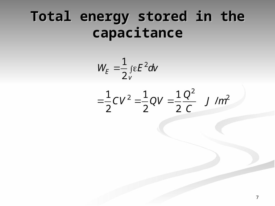
Total energy stored in the Total energy stored in the capacitancecapacitance
21
2Ev
W E dv
22 21 1 1
/2 2 2
Q
CV QV J mC
7
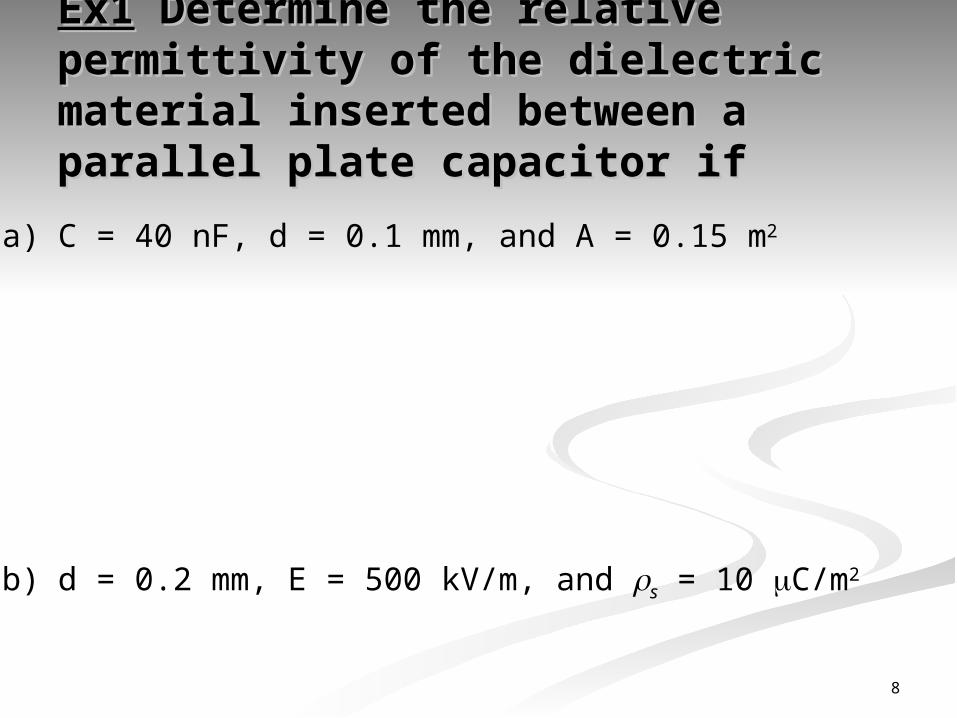
Ex1Ex1 Determine the relative Determine the relative permittivity of the dielectric permittivity of the dielectric material inserted between a material inserted between a parallel plate capacitor ifparallel plate capacitor if
a) C = 40 nF, d = 0.1 mm, and A = 0.15 m2
b) d = 0.2 mm, E = 500 kV/m, and s = 10 C/m2
8
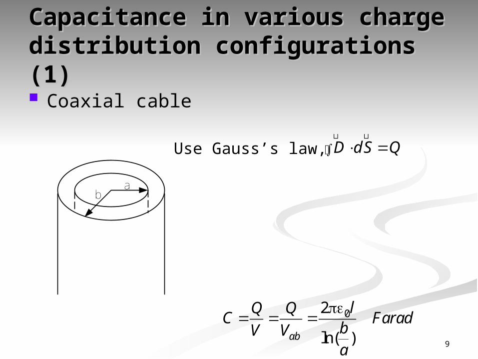
Capacitance in various charge Capacitance in various charge distribution configurationsdistribution configurations (1)(1) Coaxial cable
ab
Use Gauss’s law, D dS Q ����������������������������
02
ln( )
ab
lQ QC Farad
bV Va 9
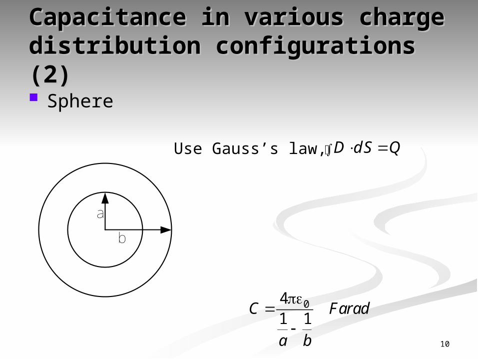
Capacitance in various charge Capacitance in various charge distribution configurationsdistribution configurations (2)(2) Sphere
Use Gauss’s law, D dS Q ����������������������������
a
b
041 1
C Farad
a b 10

Capacitance in various charge Capacitance in various charge distribution configurationsdistribution configurations (3)(3)
A parallel plate capacitor with horizontal A parallel plate capacitor with horizontal dielectric layersdielectric layers
d1
d2
1
2
A
+
-
V1
V2
+-
11
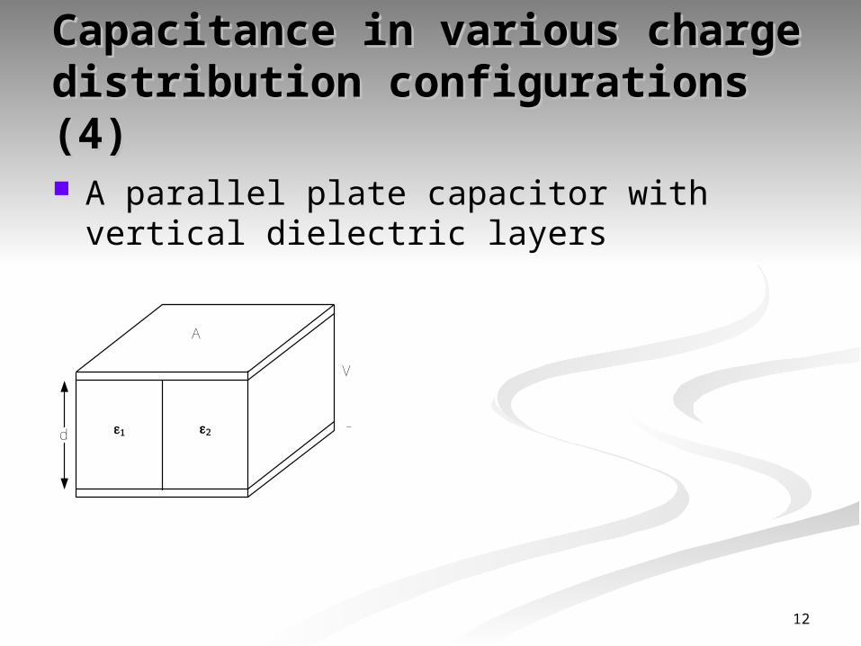
Capacitance in various charge Capacitance in various charge distribution configurationsdistribution configurations (4)(4)
A parallel plate capacitor with vertical dielectric layers
d 1 2
A
V
-
12
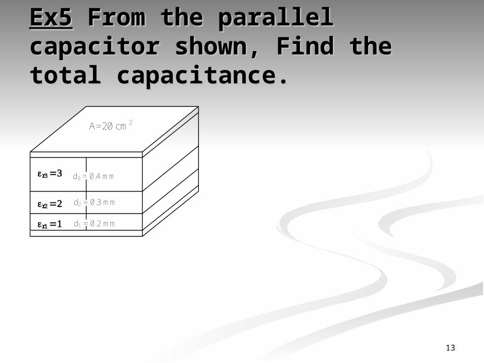
Ex5Ex5 From the parallel From the parallel capacitor shown, Find the total capacitor shown, Find the total capacitance.capacitance.
d3 = 0.4 mm
A=20 cm2
r1 1
r2 2
r3 3
d2 = 0.3 mm
d1 = 0.2 mm
13

Static magnetic fields Static magnetic fields (Magnetostatics)(Magnetostatics)
14

IntroductionIntroduction (1)(1) source of the steady magnetic field may be a per
manent magnet, and electric field changing linear ly with time or a direct current.
a schematic view of a bar magnet showing the m agnetic field. Magnetic flux lines begin and termi
nate at the same location, more like circulation.
15

IntroductionIntroduction (2)(2) Magnet i c nort h and sout h pol es are al w
ays together.
N
S
N
S
N
S
N
S
N
S
N
S
16

IntroductionIntroduction (3)(3) Oersted’s experiment shows th at current produ
ces magnetic fields that loop around the conducto r. The field grows weaker as one compass moves a
way from the source of the current.
17

- Bi o Savart l aw- Bi o Savart l aw(1)(1) - The law of Bio Savart states that at any point P the magn
itude of the magnetic field intensity produced by the differ ential element is proportional to the product of the current
, the magnitude of the differential length, and the sine of t he angle lying between the filament and a line connecting the filament to the point P at which the filed is desired.
The magnitude of the magnetic field intensity is inversely proportional to the square of the distance from the differe
ntial element to the point P.
18
- Bi o Savart l aw- Bi o Savart l aw(2)(2) The direction of the magnetic field intensity is n
ormal to the plane containing the differential fila ment and the line drawn from the filament to the point P.
- BioSavartlawi s a met hod t o det ermi ne t he magnet i c fi el d intensity. It is an analogy to Coulomb’s law of Elec trostatics.
19
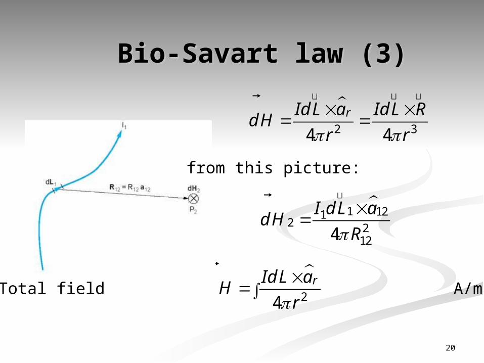
- Bi o Savart l aw- Bi o Savart l aw(3)(3)
2 34 4
rId L a Id L RdH
r r
������������������������������������������
��������������
from this picture:
1 121
2 2124
I d L adH
R
��������������
��������������
Total field A/m 24
rId L aH
r
����������������������������
20
Magnetic field intensity resulting fr Magnetic field intensity resulting fr om om an infinite length line of current an infinite length line of current
(1)(1)
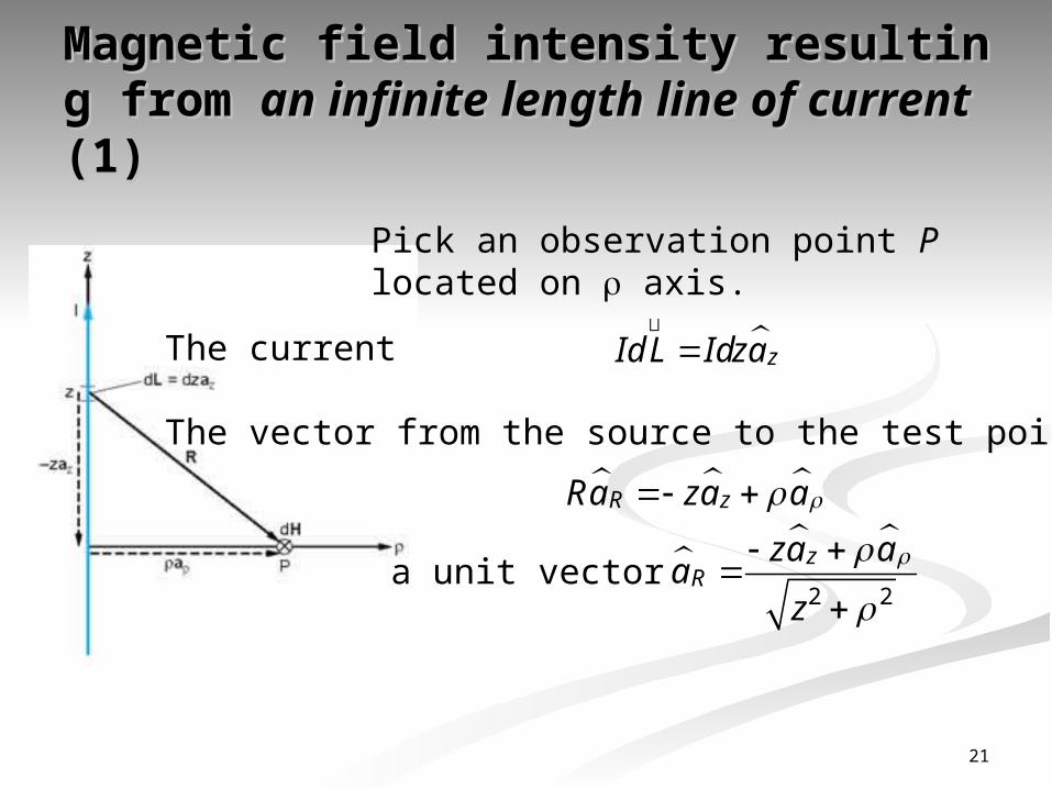
Pick an observation point P located on axis.
The current
The vector from the source to the test point is
zId L Idza
��������������
R zRa za a
a unit vector
2 2
zR
za aa
z
21
Magnetic field intensity resulting fr Magnetic field intensity resulting fr om om an infinite length line of current an infinite length line of current
(2)(2)
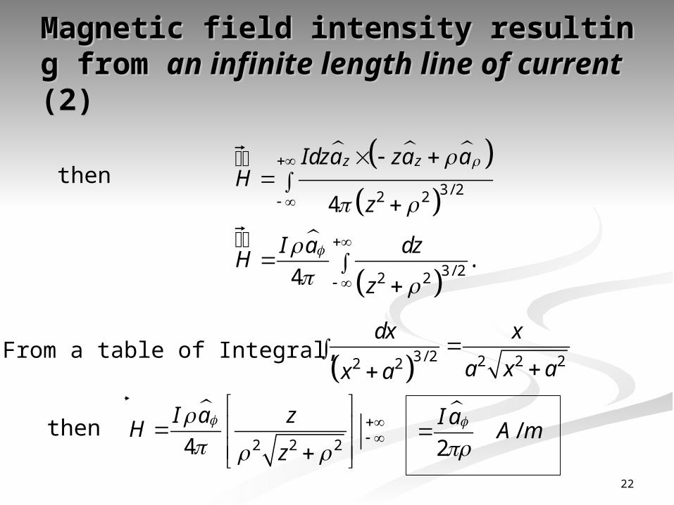
then
From a table of Integral,
3/ 22 24
z zIdza za aH
z
��������������
3/ 22 2.
4
�������������� I a dzH
z
3/ 2 2 2 22 2
dx x
a x ax a
then
2 2 24
I a zH
z
�������������� /
2
I aA m
22

Magnetic field intensity resulti Magnetic field intensity resulti ng from ng from a ring of current a ring of current (1)(1)
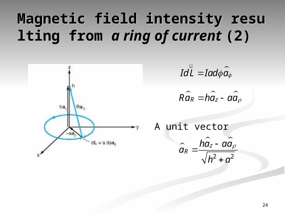
A ring is located on z = 0 plane with the radius a. The observation point is at z = h.
23
Magnetic field intensity resulti Magnetic field intensity resulti ng from ng from a ring of current a ring of current (2)(2)
Id L Iad a��������������
R zRa ha aa
2 2
zR
ha aaa
h a
A unit vector
24
Magnetic field intensity resulti Magnetic field intensity resulti ng from ng from a ring of current a ring of current (3)(3)
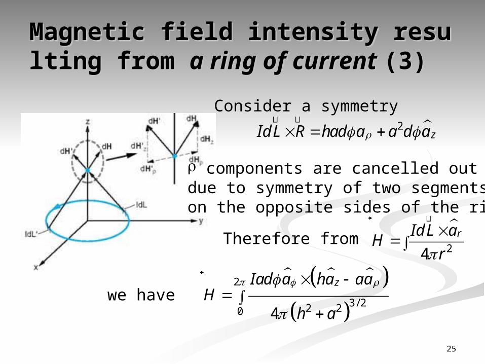
Consider a symmetry 2zId L R had a a d a
������������������������������������������
components are cancelled out due to symmetry of two segments on the opposite sides of the ring.
Therefore from 24
rId L aH
r
����������������������������
we have
2
3/ 22 20 4
zIad a ha aaH
h a
��������������
25
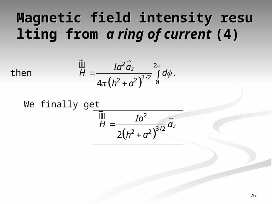
Magnetic field intensity resulti Magnetic field intensity resulti ng from ng from a ring of current a ring of current (4)(4)
then
2 2
3/ 22 2 0.
4
zIa aH d
h a
��������������
We finally get
2
3/ 22 22
��������������z
IaH a
h a
26
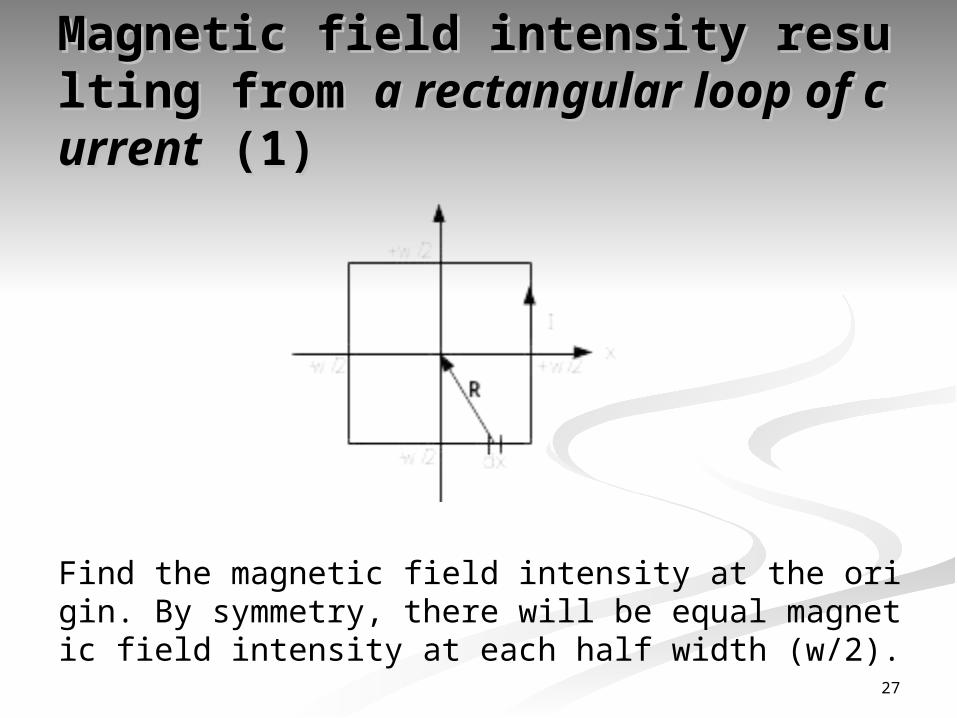
Magnetic field intensity resulti Magnetic field intensity resulti ng from ng from a rectangular loop of c a rectangular loop of c
urrenturrent (1)(1)
Find the magnetic field intensity at the origin. By symmetry, there will be equal magnetic field intensity at each half width (w/2).
27
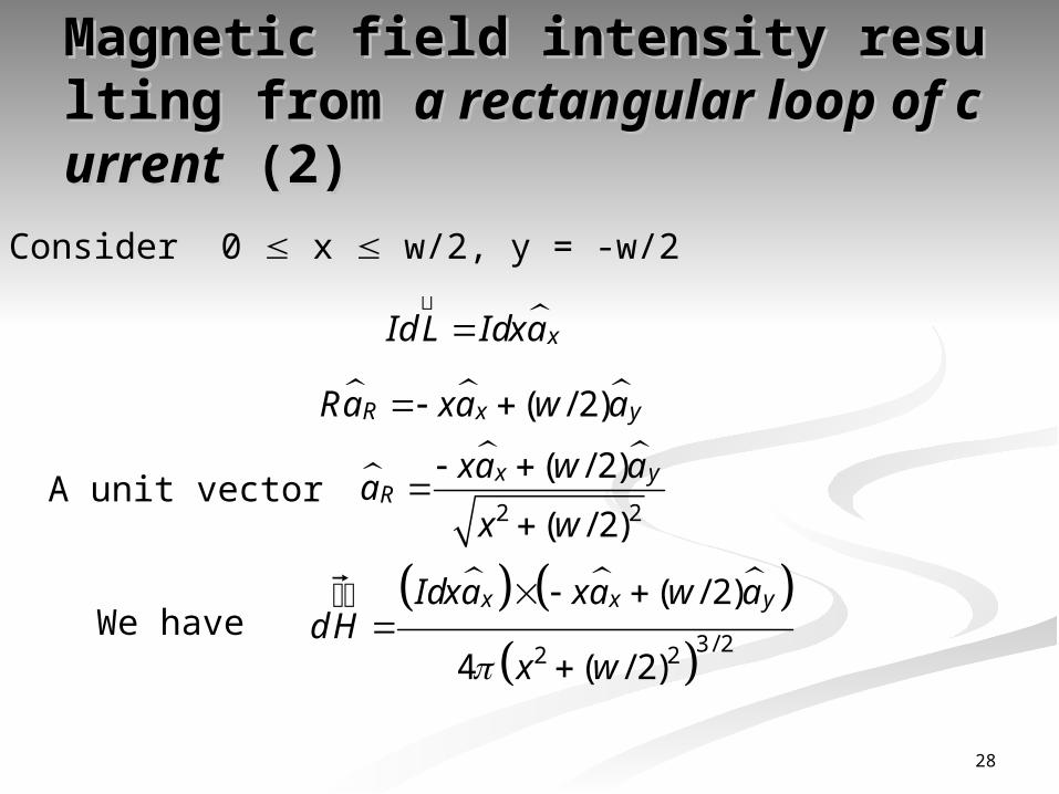
Magnetic field intensity resulti Magnetic field intensity resulti ng from ng from a rectangular loop of c a rectangular loop of c
urrenturrent (2)(2)Consider 0 x w/2, y = -w/2
xId L Idxa
��������������
( / 2)R x yRa xa w a
A unit vector
2 2
( / 2)
( / 2)
x yR
xa w aa
x w
We have
3/ 22 2
( / 2)
4 ( / 2)
x x yIdxa xa w adH
x w
��������������
28

Magnetic field intensity resulti Magnetic field intensity resulti ng from ng from a rectangular loop of c a rectangular loop of c
urrenturrent (3)(3)
3/ 22 2
( / 2)
4 ( / 2)
zIdx w a
x w
Then the total magnetic field at the origin is
/ 2
3 / 22 20
( / 2)8
4 ( / 2)
wzIdx w a
Hx w
��������������
Look up the table of integral, we find 3/ 2 2 2 22 2
dx x
a x ax a
then A/m. 2 2z
IH a
W
��������������
29

Bio-Savart law in different Bio-Savart law in different formsforms
We can express - Bio Savart law in terms of surface and volume current densities by re placing with and :
Id L��������������
KdS��������������
Jdv��������������
24
rKdS aH
r
����������������������������
where K = surface current density (A/m) I = K x width of the current sheet
and 24
rJdv aH
r
����������������������������
30
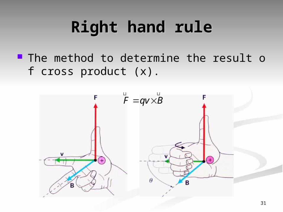
Ri ght handrul e Ri ght handrul e
Themethodtodet ermi ne t he resul t of cross product(x).
F qv B ������������������������������������������
31