Embed Size (px)
Citation preview

Eng. & Tech. Journal , Vol.32,Part (A), No.4, 2014
1007
Behavior of Plate on Elastic Foundation under Impact Load Dr. Mohammed Y. Fattah Building and Construction Engineering Department, University of Technology/ Baghdad Email: [email protected] Dr. Mohammed J. Hamood Building and Construction Engineering Department, University of Technology/ Baghdad Sura A. Abbas Building and Construction Engineering Department , University of Technology/ Baghdad
Received on: 29/1/2013 & Accepted on: 26/11/2013
ABSTRACT
In this study, nonlinear three-dimensional finite element analysis has been used to conduct a numerical investigation of the effect of applied impact load on the foundation based on sandy soil using the finite element method by ANSYS (Version 11) computer program. The 8-node brick elements are used to represent the concrete of foundation and the soil under the foundation which are denoted by Solid 65 for concrete and Solid 45 for the soil and the interface is modeled by using three-dimensional surface-to-surface (Target 170 and Contact 174) contact elements connected with concrete and soil. As a case study, a concrete foundation with dimensions (3×3×0.3) m placed on the soil 15 m deep and 9 m away from the edge of foundation is subjected to impact load. A parametric study is carried out to investigate the effect of several parameters including: foundation dimensions (geometry) and amplitude of impact load.
It was concluded that as the foundation thickness increases, the time for maximum displacement to take place increases due to geometrical damping induced by the foundation. When the length of foundation increases, the oscillation of vertical displacement decreases, which means that the foundation becomes more stable. Keywords: Plate, Elastic Foundation, Impact Load, Finite Elements.
الُمسندة على اُسس مرنة تحت تأثیر االحمال الصدمیة لواحتصرف األ
الخالصةفي ھذه الدراسة تم استعمال طریقة العناصر المحددة ثالثیة االبعاد الالخطیة لتحري ت"أثیر الحم"ل الص"دمي عل"ى
اُس"تخدمت عناص"ر حی"ث. االصدار الحادي عشر) ANSYS(االُسس الُمسندة على تربة رملیة باالستفادة من برنامج الترب""ة أس""فل س"لوكوت"م تمثی""ل ) Solid 65(خرس""انة االُس""س مثی""ل س"لوكطابوقی"ة ثالثی""ة االبع"اد ذات ثمانی""ة عق"د لت
أما منطق"ة ال"تالمس ب"ین س"طح الخرس"انة وس"طح الترب"ة ف"تم تمثیلھ"ا باس"تخدام ) Solid 45(األساس باستخدام عنصر ولدراس"ة .مربوطة بكل من الخرس"انة والترب"ة) Target 170 & Contact 174(عناصر التالمس سطح الى سطح
9م و جانبی"اً لمس"افة 15م یستند على تربة تمتد لغایة عمق ) 0.3 × 3× 3( بأبعاد يساس خرسانأ مثلحالة محددة، م"ة و القی ت"م التح"ري ع"ن ت"أثیر ع"دة عوام"ل بض"منھا أبع"اد األس"اس .ساس وُعرض ال"ى احم"ال ص"دمیةم من حافة األ
Eng. & Tech. Journal , Vol.32,Part (A), No.4, 2014 Behaviour of Plate on Elastic Foundation under Impact Load
1008
وق""د أظھ""رت النت""ائج ان""ھُ م""ع زی""ادة س""مك االس""اس ی""زداد ال""زمن ال""الزم لح""دوث االزاح""ة .القص""وى للحم""ل الص""دمياالساس یقل التذبذب في االزاحة الش"اقولیة طولزداد یوعندما .القصوى نتیجة االخماد الھندسي الذي یحتویھ االساس
.ن االساس أصبح أكثر استقراراً أمما یعني
INTRODUCTION lates on elastic foundation are often used in civil engineering problems, such as building infrastructures, tanks or silo foundations, aerospace engineering etc.
Plates are commonly used as structural elements and are subjected to wide variety of static and dynamic loads. Broadly, the dynamic loads can be classified into three major categories: • Steady state harmonic loads as in the case of machine foundations and structures
supporting rotating machines. • Random loads as in the case of seismic excitation on tall buildings, wind induced
loads on slender structures or wave loads on offshore structures. • Impulsive or shock loads as in the case of hammer foundations, missile impact, blast
loads on structures, or an aircraft crashing against a civil engineering structure. The term 'impact' covers a wide range of topics that are of great interest to do the research work.
PREVIOUS STUDIES ON PLATES RESTING ON SOIL
The literature generally refers to three distinguished methods, these are: 1) Analytical methods 2) Experimental methods 3) Numerical and finite element methods.
1. ANALYTICAL METHODS
The earliest formulation of the foundation model was done by Winkler (1867). This model represents a continuous elastic foundation by a set of closely spaced independent linear springs. Since the foundation is characterized only by springs, the Winkler type model is also called one-parameter model. The vertical displacement at the foundation surface, w is related to the intensity of applied load (q) or to the foundation reaction (p) by the modulus of the foundation and is defined as the reaction of the foundation per unit surface area per unit deflection (Rao, 2011).
In order to eliminate the deficiency of Winkler model, improved theories have been introduced on refinement of Winkler’s model, by visualising various types of interconnections such as shear layers and beams along the Winkler springs (Filonenko-Borodich, 1940; Hetényi, 1946; Pasternak, 1954; Kerr, 1964). These theories have been attempted to find an applicable and simple model of representation of foundation medium (Teodoru and Musat, 2008).
Another foundation model was proposed by Pasternak in 1954, which acquires shear interaction between springs by connecting the ends of the springs to a layer consisting of incompressible vertical elements which deform only by transverse shearing . This class of mathematical models has another constant parameter which characterizes the interaction implied between springs and hence is called two-parameter models. Two-parameter foundation models are more accurate than the one parameter (e.g. Winkler) foundation
P
Eng. & Tech. Journal , Vol.32,Part (A), No.4, 2014 Behaviour of Plate on Elastic Foundation under Impact Load
1009
model. As a special case, if the second parameter is neglected, the mechanical modeling of the foundation converges to the Winkler formulation (Teodoru, 2009).
Vlasov and Leontev (1966) gave solutions to a large number of problems of beams, plates and shells on elastic foundations, idealizing the soil medium as a two parameter model which ignores the horizontal displacements in the medium.
Rao (1969, 1971) presented general solutions to beams and plates on elastic foundations using a discrete continuum model for soil, which incorporates horizontal displacements also as a medication to Vlasov’s model. They presented the solutions using the versatile method of initial parameters
Wang and How (2001) analyzed the rectangular thick raft resting on a homogeneous elastic half space. They used the Mindlin plate theory to model the raft in order to allow for the effect of transverse shear deformation in the raft as it bends under transverse loading. By approximating the displacement function using complete two-dimensional polynomials of sufficient degree, the Ritz method was shown to be an accurate technique in solving this class of the raft-soil interaction problems. They compared the settlement and the bending moment of the raft for various loading conditions. EXPERIMENTAL METHODS
Al-Azawi (1984) tested experimentally simply supported reinforced concrete slabs subjected to both impact loading and static loading. The impact load was produced by a freely falling steel mass which impacted a (50 mm diameter x 500 mm long) cylindrical steel bar placed in contact with the slab at its center. The adopted variables were the falling mass, the boundary conditions of the slabs, and the slab thickness. A theoretical analysis was carried out to determine the deflection-time history at the center of a reinforced concrete slab. The central transient deflection of the slabs was calculated and found in a good agreement with the experimental transient deflection.
Chen et al. (1988) developed a small laboratory test using low velocity impact technique. Using the experimental technique on buried cylindrical structures, the effects of dropping heights and different buried depths were studied. They concluded that dynamic soil arching, as a form of load release at the roof center, occurred.
Abbasi et al. (1992) analyzed reinforced concrete beams and plates under impact loading. Three-dimensional nonlinear finite element analysis of the reinforced concrete has been modeled. Experiments were conducted in the laboratory involving drop hammer loading on circular concrete slabs NUMERICAL AND FINITE ELEMENT METHODS
Emrich et al. (1982) used finite element method to investigate the behavior of reinforced concrete beams subjected to impact load. Nonlinear constitutive laws for concrete and steel were assumed. Newmark implicit time scheme was used to solve nonlinear dynamic equations.
Saha (1997) studied the dynamic stability of a rectangular plate on elastic foundation subjected to uniform dynamic loads and supported on completely elastically restrained boundaries. The effects of stiffness and geometry of the foundation were also studied, in addition to boundary conditions, static load factor, in-plane load ratio and aspect ratio on
Eng. & Tech. Journal , Vol.32,Part (A), No.4, 2014 Behaviour of Plate on Elastic Foundation under Impact Load
1010
the stability boundaries of the plate for first- and second-order simple and combination resonance.
Karsin (2004) studied the exact stiffness, geometric stiffness and consistent mass matrices of the beam element on two-parameter elastic foundation extended to solve plate problems. Some examples of circular and rectangular plates on two-parameter elastic foundation including bending, buckling and free vibration problems were solved by the finite grid solution.
Celep and Guler (2004) studied the static behavior and forced oscillations of a rigid circular plate supported by a tensionless Winkler elastic foundation by assuming that the plate is subjected to a uniformly distributed load and a vertical load having an eccentricity. It was observed that lift-off had a significant effect on the motion of the plate, the recognizable period of the oscillations is lengthened and the amplitudes become larger, because the tensionless foundation model is relatively less constrained compared to the conventional one.
Tee (2005) studied the dynamic response of a finite circular plate resting on sand by using ABAQUS program. In the analysis, a free-drop impact system was considered to generate the dynamic loading on the plate free surface. Two finite element models were built, one with a slide line underneath the target plate and another one without the slide line. The numerical results of the finite element method for the radial strain at the bottom of the target plate were compared with the experimental measurement.
Muslih (2007) studied the behavior of rectangular slabs with different boundary conditions and subjected to impact loading caused by falling mass. The model slabs were of dimensions (500 x 500 x 20) mm and the independent variables were the falling mass, the height of drop and the deformation constant. Also, the effects of moment of inertia were discussed. Theoretical analysis based on the numerical solution of the slab impact integral equation was carried out to determine the impact force and deflection time histories, the strain energy absorbed by the slabs and the maximum bending moment. Effect of slab boundary conditions on impact response of slab was also discussed.
Civalek et al. (2007) carried out an investigation to introduce the numerical solution of geometrically nonlinear dynamic problem of rectangular plates resting on elastic foundation. The effects of Winkler and Pasternak foundation parameters on the dynamic response of plates had been investigated. Four types of loadings, namely, a uniform step load of infinite duration, sinusoidal loading of finite duration (t = 0.16 sec.), N-shaped pulse load of finite (t = 0.2 sec.), and triangular load of finite (t = 0.16 sec.) duration, have been considered. It appeared that the shear parameter G of the Pasternak foundation and stiffness parameter K of the Winkler foundation have a significant influence on the dynamic response of the plates. The effect of Winkler parameter K, on the displacements was greater than the Pasternak parameter, G. However, the step load of infinite duration had bigger effect on the dynamic response of the rectangular plates on elastic foundation compared with the other dynamic loads which considered in this study.
Based on the results of comparative analysis of the circular plate on deformable foundation Jankovski and Skarzauskas (2010) reported that in case of physical nonlinearity, the stress-strain state in soil with plastic shear residual strains was more close to reality than in case of usual analysis of the structures on deformable foundation. Increase of the plate settlements from 15.8 cm in linear analysis to 22.5 cm in nonlinear

Eng. & Tech. Journal , Vol.32,Part (A), No.4, 2014 Behaviour of Plate on Elastic Foundation under Impact Load
1011
analysis was strongly accented for physical nonlinearity evaluation necessity. Deformation character of soil shear surface and spread of strains in the layers of soil were formed along the plate perimeter. Stresses intensity in the foundation decreased from 0.8 MPa in linear analysis to 0.6 MPa in nonlinear analysis due to the development of soil strains. Maximum stress intensities in the plate under the Huber-Mises criterion increased from 161 MPa to 182 MPa due to the increment of soil flexibility in nonlinear analysis.
Based on the literature reviewed, it is found that many literatures are reported on nonlinear behavior of soil and concrete, and considerable amount of literatures are reported on the three-dimensional nonlinear analysis of plate on elastic foundation, but very few studies adopted the dynamic response of soil-structure interaction problems. The present research aims to analyze the foundation by three-dimensional nonlinear finite element method using ANAYS 11 finite element software, in which both the structure and its supporting soil are modeled as continua. The foundation and soil are discretised by eight nodded brick elements. The soil is modeled as elasto-plastic material. The finite element procedure is used to analyze the foundation subjected to impact load.
DESCRIPTION OF THE PROBLEM
The present finite element formulations and solution procedures are applied for the transient dynamic analysis of a variety of plate on elastic foundation examples with material nonlinearities. A concrete foundation with dimensions (3×3×0.3) m is placed on the foundation soil (15 m) deep and (9 m) away from the edge of plate. The boundary conditions are chosen such that all the lateral boundaries and the base of the problem are restricted both horizontally and vertically. The geometry, loading conditions and all details of the problem are shown in Figure (1).
The foundation is subjected to the transient dynamic load described by the following equation:
f (t) = 0.5 - 0.5 cos(2πt/To) …(1) p (t) = po f (t) … (2)
Where: T: time for each point, To: impact duration, and po: the peak amplitude of the load. The loading function is shown in Figure (2). The duration of this dynamic load is (0.5 sec.) with a time step (Δt = 0.01 sec.). The properties of the material for concrete and soil are summarized in Table (1). The soil foundation is cohesionless dense sand with an angle of internal friction, f equals 40o. The nonlinear behaviour for both soil and concrete are considered. The Drucker-Prager model is used to model the soil elasto-plastic behavior, while the concrete parameter is used for modeling the behavior of concrete. The 8-node brick elements in ANSYS are used to represent the concrete of foundation and the soil under the foundation which are denoted by Solid 65 for concrete and Solid 45 for the soil and the interface elements are modeled by using three-dimensional surface-to-surface (Target 170 and Contact 174) contact elements connected with concrete and soil.

Eng. & Tech. Journal , Vol.32,Part (A), No.4, 2014 Behaviour of Plate on Elastic Foundation under Impact Load
1012
The load is applied at the foundation center for eccentric loading and at distances of (e/B = 0.1, 0.2, 0.3) away from the center for concentric loading. No damping has been considered in this problem.
PARAMETRIC STUDY
A parametric study is performed to investigate the influence of several important parameters on the behaviour of the foundation on elastic-plastic soil subjected to impact loads. The parameters studied are foundation dimensions (length, width and thickness) and load amplitude.
The analysis is carried out by the program (ANSYS V11). The parameters used in the analysis are summarized in Table (2). EFFECT OF FOUNDATION THICKNESS
Three values for foundation thickness are chosen (0.3, 0.5, and 0.75) m to investigate their effect on the analysis results. These values are checked to maintain the foundation requirements under static loads. The study includes investigating the effect of thickness variation on vertical displacement and vertical stress.
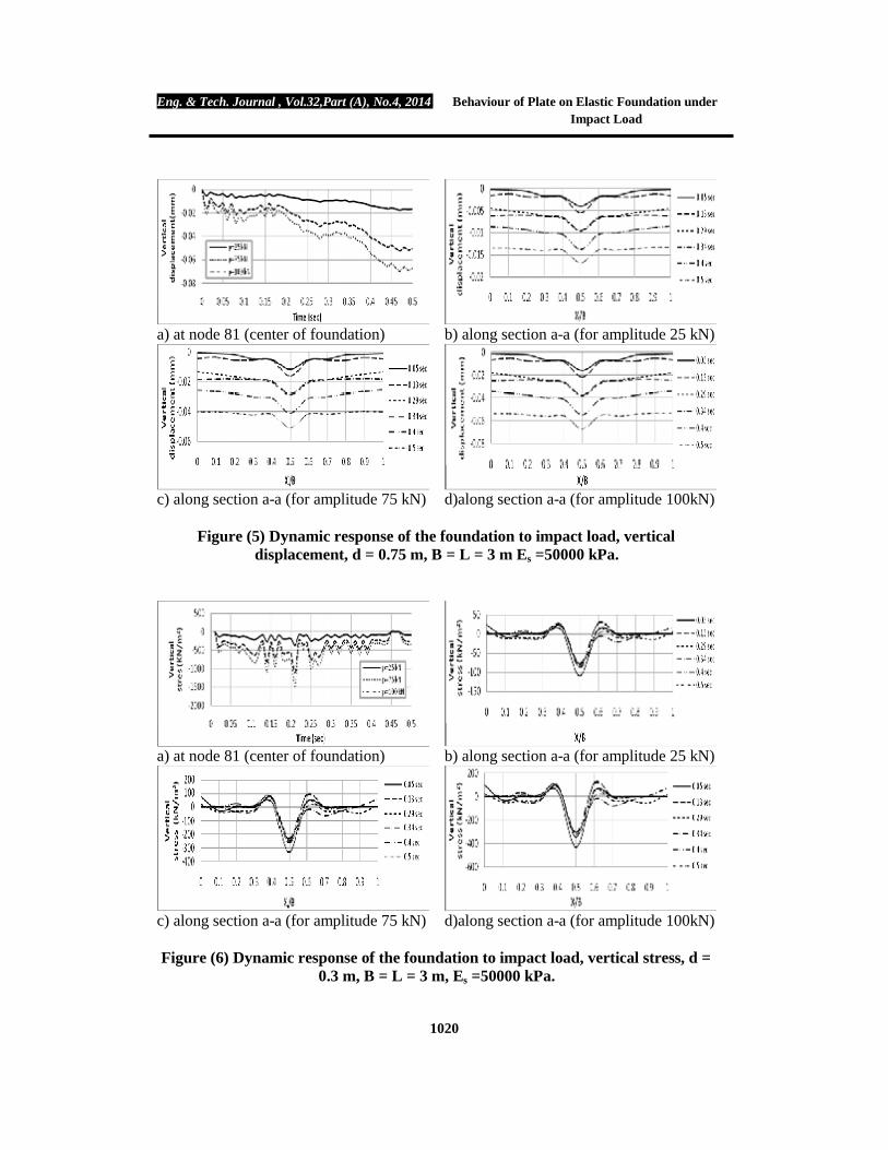
Figures (3) to (5) show the effect of foundation thickness under three values of load amplitude (25, 75 and 100) KN on the time history of vertical displacement at node 81 Figure (1) and the relationship between the vertical displacement and distance along section a-a Figure (1) at different times. The effect of foundation thickness under three values of load amplitude (25, 75 and 100) KN in relation with vertical stress and time, and the relationship between the vertical stress (σz) and distance at different times are presented in Figures (6) to (8). From Figures (3) to (5), it can be noticed that when the thickness of foundation increases from (t = 0.3 to 0.5 and 0.75) m for amplitude load (po = 25 kN), the maximum vertical displacement at node (81) in the center of foundation decreases by about (44.6 and 57.4) %, respectively. It is also noticed that the increase in the thickness from (t = 0.3 to 0.5 and 0.75) m for amplitude load (po = 75 kN), the maximum vertical displacement at node (81) in the center of foundation is decreased to about (0.06803, 0.05235) mm, respectively. So, the ratio of maximum vertical displacement at thickness (0.5, 0.75) m to maximum vertical displacement at the foundation thickness 0.3 m decreases by about (44.6 and 57.4) %Also, it can be seen that for the increase in thickness from (t = 0.3 to 0.5 and 0.75) m under an amplitude load (po = 100 kN), the maximum vertical displacement at node (81) in the center of foundation is decreased to (0.091, 0.070) mm, respectively. So, the maximum vertical displacement at thickness (0.5, 0.75) m is decreased by about (44.6 and 57.4) % with respect to the maximum vertical displacement at the foundation thickness 0.3 m.
From Figure (3), the maximum vertical displacement takes place at time (0.26 sec.) for thickness (0.3 m) under amplitude loads (25, 75 and 100) kN, while the maximum vertical displacement occurs at time (0.42 sec.) for thickness (0.5 m) under the same amplitude loads, as in Figure (4).
On the other hand, the maximum vertical displacement takes place at time (0.47 sec.) for thickness (0.75 m) and amplitude loads (25, 75 and 100) kN, Figure (5). This means that as the foundation thickness increases, the time for maximum displacement to take place increases due to the geometrical damping induced by the foundation.
Eng. & Tech. Journal , Vol.32,Part (A), No.4, 2014 Behaviour of Plate on Elastic Foundation under Impact Load
1013
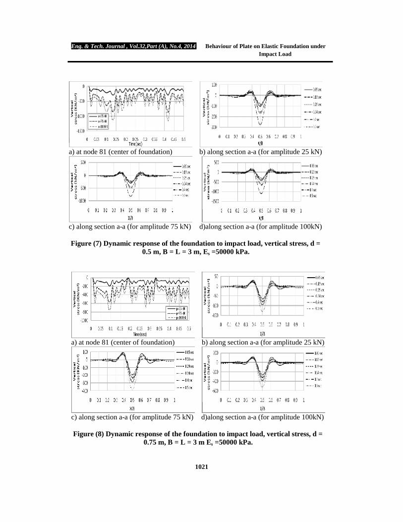
Figures (6) to (8) reveal that for the increase in the thickness from (t = 0.3 to 0.5 and 0.75) m for amplitude load (po = 25 kN), the maximum vertical stresses at node (81) found at thickness of (0.5, 0.75) m are (287.21, 184.45) kPa. So, the ratio of the maximum vertical stress at thickness (0.5, 0.75) m to the maximum vertical stress at the foundation thickness 0.3 m decreases by about (21.7, 49.7) %. It can be observed that when the thickness of foundation increases from (t = 0.3 to 0.5 and 0.75) m for amplitude load (po = 75 kN), the maximum vertical stress at node (81) decreases by about (21.7, 49.7) %, respectively.
It can also be seen that when the increase in the thickness from (t = 0.3 to 0.5 and 0.75) m for amplitude load (p = 100 kN), the maximum vertical stress at node (81) is found to be (1148.84, 737.806) kPa. So, the maximum vertical stress at thickness (0.5, 0.75) m decreases by (21.7, 49.7) % with respect to the maximum vertical stress at the foundation thickness 0.3 m.
From Figure (6), the maximum vertical stress takes place at time (0.21 sec.) for thickness (0.3 m) and amplitude loads (25, 75 and 100) kN, while the maximum vertical stress occurs at time (0.42 sec.) for thickness (0.5 m) under the same amplitude loads, as in Figure (7).
On the other hand, the maximum vertical stress takes place at time (0.09 sec.) for thickness (0.75 m) and amplitude loads (25, 75 and 100) KN, see Figure (8).
It is obvious from these figures that the vertical displacement and stress decrease when the thickness of foundation increases under the same applied loads, and this is similar to the behavior of structural concrete subjected to static loads where the increase in thickness of foundation leads to the gradual increase of foundation rigidity, and this in turn increases the moment of inertia which results in decrease in vertical displacement and stress in the concrete.
From the illustrated relationships between the vertical stress and time, it can be noticed that: Ø All values of vertical stress are negative, this means that the stresses represent
compression; the concrete has the ability to withstand compression stresses. Ø The relationships included oscillation with time to be up to the time in which the
amount of vertical stress is zero or close to zero, i.e., the curves close to the formation of stresses are closer to the tensile stresses, which means that the loading function can be described as periodically.
From the illustrated relationships between the vertical displacement and time, it can be noticed that The mathematical behavior of the curves is a function of decreasing, any more, the proceeding of the time leads to decrease the vertical displacements of a given start function to change the behavior. The genesis of cumulative displacements from the precedent loads begins the disposal of the curve to get off, because the foundation is unable to withstand the applied loads; the concrete is a brittle material. From the illustrated relationships between the vertical displacements and stresses along a distance, it can be stated that the variation of vertical displacements and stresses reveals a response similar to the behavior of structural concrete subjected to static loads. At the point of load application, the greatest displacement is generated as well as the
Eng. & Tech. Journal , Vol.32,Part (A), No.4, 2014 Behaviour of Plate on Elastic Foundation under Impact Load
1014
greatest stress, and then the values for each of the stresses and displacements start decreasing towards the parties. EFFECT OF FOUNDATION LENGTH
Applying the impact load on the foundation, the effect of foundation length is studied. Four values for foundation length (3, 4, 5 and 6) m. (where L =3 m is studied in the previous section) are used, while the foundation width (B) is kept constant (3 m) with damping ratio equals zero and thickness of foundation equals 0.3 m.
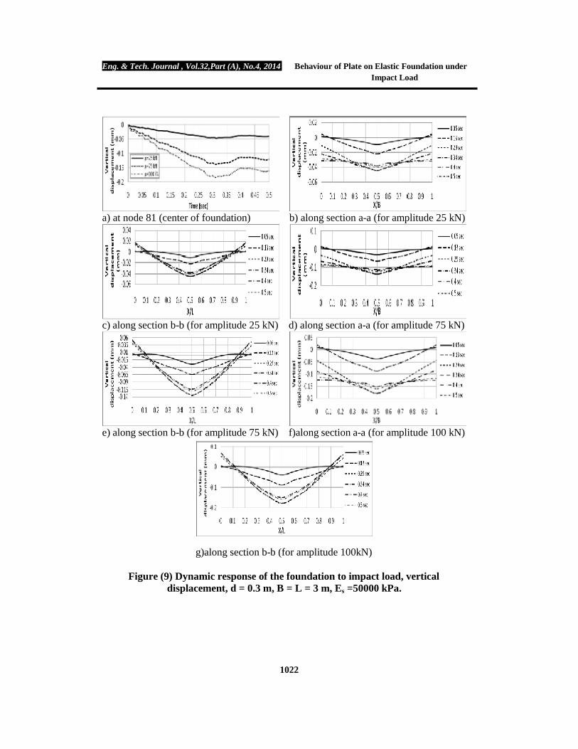
Figures (9) to (11) show the results of studying the effect of foundation length under different values of load amplitude (po = 25, 75, 100) kN on the vertical displacement, and the relationship between the vertical displacement and distance at different times, while Figures (12) to (14) depict the results of the effect of foundation length on the time history of vertical stress (σz) and the relationship between the vertical stress and distance at different times. The time variation of the vertical displacement is presented in Figures (9) to (11), while the vertical stress and time relations are presented in Figures (12) to (14). It can be concluded that: Ø When increasing the foundation length, it is noticed that the oscillation for the
vertical displacement with time diminishes, which means that the foundation becomes more stable. While, loading the soil under the location of point load makes it well compacted (more dense) which leads to push the nearest soil to the side, leading to uplift the foundation sides to the positive area, as shown in Figures (9), (10) and (11).
Ø Increasing the foundation length will lead to widen the influenced region around the loading point, as well as confinement of soil because of the nearest layers which will cause other waves to act around the loading point, Figure (14).
Ø From Figure (13 f), it can be observed that there is some of oscillation on sides of the load, and this is due to the small area which is not enough to attenuate the oscillation generated from the impact load.
Ø For amplitude loads (p = 25, 75 and 100) kN, it can be noticed that when the length of foundation increases from (L = 3 to 6) m, the maximum vertical displacement at node (81) in the center of foundation increases by about (12.5, 19.13 and 20.8) %, respectively under the same amplitudes of load, while the maximum vertical stress decrease by about (42.2, 48.2 and 57.2) %, respectively.
Ø From Figure (9), it can be seen that the maximum vertical displacement takes place at time (0.31 sec.) for length (4 m) and amplitude loads (25, 75 and 100) kN, while the maximum vertical displacement occurs at time (0.5 sec.) for length (5 m) and the same amplitude loads, Figure (10). Also, it can be seen that the maximum vertical displacement takes place at time (0.47 sec.) for length (6 m) and the same amplitude loads, Figure (11).
Ø From Figure (12), it can be noticed that the maximum vertical stress takes place at time (0.28 sec.) for length (4 m) and amplitude loads (25, 75 and 100) kN, while the maximum vertical stress occurs at time (0.39 sec.) for length (5 m) and the same amplitude loads, see Figure (13). Also, it can be seen that the maximum vertical stress occurs at time (0.39 sec.) for length (6 m) and the same amplitude loads, Figure (14).

Eng. & Tech. Journal , Vol.32,Part (A), No.4, 2014 Behaviour of Plate on Elastic Foundation under Impact Load
1015
From these figures, it is concluded that when the length of foundation increases, the maximum vertical stresses decreases. This is due to increase in area of foundation so that the vertical stress will decrease due to increase of the moment of inertia. But, any increase in the length will result in increasing the maximum vertical displacement; this can be attributed to the gradual decrease of foundation rigidity, i.e., the foundation turns to be more flexible.
CONCLUSIONS
As a result of the finite elements analysis carried out in this study, the following conclusions could be made: 1) As the foundation thickness increases, the time for maximum displacement to take
place increases due to the geometrical damping induced by the foundation. When the thickness of foundation increases from (t = 0.3 to 0.5 and 0.75) m for amplitude load (po = 25, 75 and 100) kN, the maximum vertical displacement at the center of foundation decreases by about (45 and 58) %, and the maximum vertical stress decreases by about (22 and 50) %, respectively.
2) When the length of foundation increases, the oscillation of vertical displacement decreases, which means that the foundation becomes more stable.
3) When the length of foundation increases from (L = 3 to 6) m, the maximum vertical displacement at the center of foundation increases by about (13, 19 and 21) %, respectively under the same amplitudes of load, while the maximum vertical stress decreases by about (42, 48 and 57) %, respectively.
REFERENCES [1].Abbasi, M.S.A., Baluch, M. H., Azad, A. K. and Abdel-Rahman, H.H. (1992),
"Nonlinear Finite Element Modeling of Failure Modes in Reinforced Concrete Slabs”, Journal of Computers and Structures, VoI. 42, No. 5, pp.815-823.
[2].Al-Azawi, T. K. (1984), “Impact of Reinforced Concrete Slabs”, Ph.D. Thesis, University of Sheffield, England.
[3].ANSYS Manual, Version. 11, (2007): SAS IP, Inc. [4].Celep, Z. and Guler, K. (2004), "Static and Dynamic Responses of a Rigid Circular
Plate on a Tensionless Winkler Foundation", Journal of Sound and Vibration, Vol. 276, pp. 449-458.
[5].Civalek, M., Baki, O. and Altug, Y. (2007), “Nonlinear Transient Dynamic Response of Clamped Rectangular Plates on Two-Parameter Foundations by the Algorithm of the Singular Convolution”, International Journal of Science and Technology, Vol. 2, No. 2, pp. 165-177.
[6].Chen, H. L., Lin, W., Keer, L. M. and Shah, S. P. (1988), "Low Velocity Impact of an Elastic Plate Resting on Sand”, Journal of Applied Mechanics, Vol. 55, pp. 887-894.
[7].Emrich, F., Herter, J. and Puffer, G. (1982), "Nonlinear Finite Element Analysis of Reinforced Concrete Beams under Impact Load in Comparison with Experimental Results”, Computers and Structures, BAM, Berlin (West), Vol. 4, No. 2, pp. 455-471.
[8].Filonenko-Borodich, M. M. (1940), “Some Approximate Theories of the Elastic Foundation (in Russian)”, Uchenye Zapiski MGU, 46, 3-18.
Eng. & Tech. Journal , Vol.32,Part (A), No.4, 2014 Behaviour of Plate on Elastic Foundation under Impact Load
1016
[9].Hetenyi, M. (1946), “Beams on Elastic Foundations”, Ann Arbor, University of Michigan Press.
[10].Jankovski, V. and Skarzauslcas, V. (2010), "The Physically Nonlinear Contact Analysis of Circular Plate on Deformable Foundation by ANSYS Software", Proceeding of the 10th International Conference, on “Modern Building Materials, Structures and Techniques”, May 19-21, Vilnius, Lithuania, pp. 910-917.
[11].Karasin, A. (2004), “An Improved Finite Grid Solution for Plates on Generalized Foundations”, Ph.D. Thesis, University of the Middle East Technical.
[12].Kerr, A. D. (1964), “Elastic and Viscoelastic Foundation Models”, J. of Applied Mech., ASME, 31(3), 491-498.
[13].Levinton, Z. (1949), “Elastic Foundation Analyzed by the Method of Redundant Reactions”, Trans., ASCE, Vol. 114, pp. 40- 52.
[14].Muslih, S. K. (2007), “Effect of Boundary Conditions on Impact Resistance of Concrete Slabs”, M.Sc. Thesis, University of Technology, Building and Construction Engineering Department, Iraq, pp. 114.
[15].Pasternak, P. L. (1954), “Fundamental of a New Method of Analysis of an Elastic Foundation by Means of Two Foundation Constants (in Russian)”, Gos. Izd. Lit.po Strait i Arkh., Moscow, USSR.
[16].Rao, N. S. V. (2011), “Foundation Design: Theory and Practice” John Wiley & Sons (Asia), First Edition, Pte Ltd.
[17].Rao, S. S. (1969), “Mechanical Vibrations”, Addison-Wesley Publishing Co., USA. (Cited by Rao, 2011).
[18].Rao, S. S. (1971), “The Finite Element Method in Engineering”, Pergamon Press, Oxford, U.K. (Cited by Rao, 2011).
[19].Saha, K.N. (1997), “Dynamic Stability of Rectangular Plate on Non-Homogeneous Winkler Foundation”, Computers and Structures, Vol. 63, No. 6, pp. 1213-1222.
[20].Shaban, M., Shariyat, M. and Alipour, M. (2010), “A Semi-Analytical Solution for Free Vibration and Modal Stress Analyses of Circular Plates Resting on Two-Parameter Elastic Foundations”, Journal of Solid Mechanics, Vol. 2, No. 1, pp. 63-78.
[21].Tee, C. H. (2005), “Dynamic Response of Plates and Buried Structures”, M.Sc. Thesis, University of West Virginia.
[22].Teodoru, B. (2009), “Beam on Elastic Foundation the Simplified Continuum Approach”, University of Gheorghe Asachi, Vol. 4.
[23].Teodoru, B. and Musat, V. (2008), “Beam Elements on Linear Variable Two- Parameter Elastic Foundation”, University of Gheorghe Asachi, Vol. 3.
[24].Vlasov, V. Z. and Leontev, N. N. (1966), “Beams, Plates and Shells on Elastic Foundation (in Russian)”, Fizmatgiz, Moscow, USSR. (Cited by Rao, 2011).
[25].Wang, C.M. and How, Y.C. (2001), “Analysis of Rectangular Thick Rafts on an Elastic Half Space”, Computers and Geotechnics, Vol. 28, Issue 3, pp. 161-184.
[26].Winkler, E. (1867) Die Lehre von der elasticitaet und festigkeit, Prag Dominicus, Berlin, p.p. 182. (Cited by Rao, 2011).

Eng. & Tech. Journal , Vol.32,Part (A), No.4, 2014 Behaviour of Plate on Elastic Foundation under Impact Load
1017
Table (1) Material properties for concrete and soil in the basic problem.
Concrete
Symbol Definition Value
f′c Compressive strength (MPa) 25
cE Young’s modulus (MPa) 23500
Tensile strength (MPa) 3.1 ν Poisson’s ratio 0.15* ρc Density (kg/m3) 2400
Interface µ Coefficient of friction 0.6*
Soil
Es Young’s modulus (MPa) 50 cu Cohesion 0 φ Frication angle 40o ν Poisson’s ratio 0.3* ρs Density (kg/m3) 1800
Notes: *Assumed value, cE = 4700 f c′ and = 0.62 f c′
Table (2) Parameters of the main problem. parameter Range of value Unit
Foundation thickness 0.3, 0.5, 0.75 m Foundation length 3, 4, 5, 6 m Load amplitude, po 25, 75, 100 kN

Eng. & Tech. Journal , Vol.32,Part (A), No.4, 2014 Behaviour of Plate on Elastic Foundation under Impact Load
1018
Figure (1) Typical finite element mesh.
Figure (2) The loading function.

Eng. & Tech. Journal , Vol.32,Part (A), No.4, 2014 Behaviour of Plate on Elastic Foundation under Impact Load
1019
a) at node 81 (center of foundation)
b) along section a-a (for amplitude 25 kN)
c)along section a-a (for amplitude 75 kN)
d)along section a-a (for amplitude 100 kN)
Figure (3) Dynamic response of the foundation to impact load, vertical displacement, d = 0.3 m, B = L = 3 m, Es =50000 kPa.
a) at node 81 (center of foundation)
b) along section a-a (for amplitude 25 kN)
c)along section a-a (for amplitude 75 kN) d)along section a-a (for amplitude 100 kN)
Figure (4) Dynamic response of the foundation to impact load, vertical displacement, d = 0.5 m, B = L = 3 m, Es =50000 kPa.
Eng. & Tech. Journal , Vol.32,Part (A), No.4, 2014 Behaviour of Plate on Elastic Foundation under Impact Load
1020
a) at node 81 (center of foundation) b) along section a-a (for amplitude 25 kN)
c) along section a-a (for amplitude 75 kN) d)along section a-a (for amplitude 100kN)
Figure (5) Dynamic response of the foundation to impact load, vertical displacement, d = 0.75 m, B = L = 3 m Es =50000 kPa.
a) at node 81 (center of foundation) b) along section a-a (for amplitude 25 kN)
c) along section a-a (for amplitude 75 kN) d)along section a-a (for amplitude 100kN)
Figure (6) Dynamic response of the foundation to impact load, vertical stress, d = 0.3 m, B = L = 3 m, Es =50000 kPa.
Eng. & Tech. Journal , Vol.32,Part (A), No.4, 2014 Behaviour of Plate on Elastic Foundation under Impact Load
1021
a) at node 81 (center of foundation) b) along section a-a (for amplitude 25 kN)
c) along section a-a (for amplitude 75 kN) d)along section a-a (for amplitude 100kN)
Figure (7) Dynamic response of the foundation to impact load, vertical stress, d = 0.5 m, B = L = 3 m, Es =50000 kPa.
a) at node 81 (center of foundation) b) along section a-a (for amplitude 25 kN)
c) along section a-a (for amplitude 75 kN) d)along section a-a (for amplitude 100kN)
Figure (8) Dynamic response of the foundation to impact load, vertical stress, d = 0.75 m, B = L = 3 m Es =50000 kPa.
Eng. & Tech. Journal , Vol.32,Part (A), No.4, 2014 Behaviour of Plate on Elastic Foundation under Impact Load
1022
a) at node 81 (center of foundation) b) along section a-a (for amplitude 25 kN)
c) along section b-b (for amplitude 25 kN) d) along section a-a (for amplitude 75 kN)
e) along section b-b (for amplitude 75 kN) f)along section a-a (for amplitude 100 kN)
g)along section b-b (for amplitude 100kN)
Figure (9) Dynamic response of the foundation to impact load, vertical displacement, d = 0.3 m, B = L = 3 m, Es =50000 kPa.

Eng. & Tech. Journal , Vol.32,Part (A), No.4, 2014 Behaviour of Plate on Elastic Foundation under Impact Load
1023
a) at node 81 (center of foundation) b) along section a-a (for amplitude 25 kN)
c) along section b-b (for amplitude 25 kN) d) along section a-a (for amplitude 75 kN)
e) along section b-b (for amplitude 75 kN) f)along section a-a (for amplitude 100 kN)
g) along section b-b (for amplitude 100 kN)
Figure (10) Dynamic response of the foundation to impact load, vertical displacement, d = 0.3 m, B = L = 3 m, Es =50000 kPa.

Eng. & Tech. Journal , Vol.32,Part (A), No.4, 2014 Behaviour of Plate on Elastic Foundation under Impact Load
1024
a) at node 81 (center of foundation) b) along section a-a (for amplitude 25 kN)
c) along section b-b (for amplitude 25 kN) d) along section a-a (for amplitude 75 kN)
e) along section b-b (for amplitude 75 kN) f) along section a-a (for amplitude 100kN)
g) along section b-b (for amplitude 100 kN)
Figure (11) Dynamic response of the foundation to impact load, vertical displacement, d = 0.3 m, B = L = 3 m, Es =50000 kPa.

Eng. & Tech. Journal , Vol.32,Part (A), No.4, 2014 Behaviour of Plate on Elastic Foundation under Impact Load
1025
a) at node 81 (center of foundation) b) along section a-a (for amplitude 25kN)
c) along section b-b (for amplitude 25 kN) d) along section a-a (for amplitude 75kN)
e) along section b-b (for amplitude 75kN) f) along section a-a (for amplitude 100kN)
g) along section b-b (for amplitude 100kN)
Figure (12) Dynamic response of the foundation to impact load, vertical stress, d = 0.3 m, B = L = 3 m, Es =50000 kPa.

Eng. & Tech. Journal , Vol.32,Part (A), No.4, 2014 Behaviour of Plate on Elastic Foundation under Impact Load
1026
a) at node 81 (center of foundation) b) along section a-a (for amplitude 25kN)
c) along section b-b (for amplitude 25kN) d) along section a-a (for amplitude 75kN)
e) along section b-b (for amplitude 75kN) f) along section a-a (for amplitude 100kN)
g) along section b-b (for amplitude 100kN)
Figure (13) Dynamic response of the foundation to impact load, vertical stress, d = 0.3 m, B = L = 3 m, Es =50000 kPa.

Eng. & Tech. Journal , Vol.32,Part (A), No.4, 2014 Behaviour of Plate on Elastic Foundation under Impact Load
1027
a) at node 81 (center of foundation) b) along section a-a (for amplitude 25kN)
c) along section b-b (for amplitude 25kN) d) along section a-a (for amplitude 75kN)
e) along section b-b (for amplitude 75kN) f) along section a-a (for amplitude 100kN)
g)along section b-b (for amplitude 100kN) Figure (14) Dynamic response of the foundation to impact load, vertical stress, d =
0.3 m, B = L = 3 m, Es =50000 kPa.