Embed Size (px)
Citation preview

11N Wireless Router
EnGenius Gold
11N Wireless Router V1.0
1
1. Introduction ................................................................................................................................................................7
1.1. Package Contents.............................................................................................................................................7
1.2. System Requirements.......................................................................................................................................7
1.3. Introduction .....................................................................................................................................................8
1.4. LED Overview ...................................................................................................................................................9
1.5. Before you Begin............................................................................................................................................10
1.6. Considerations for Wireless Installation..........................................................................................................10
2. Configure PC/Laptop Network Interface ...................................................................................................................11
2.1. Windows XP/Vista ..........................................................................................................................................11
2.2. Windows 7 .....................................................................................................................................................14
2.3. Apple MacOS .................................................................................................................................................16
3. Setup your Router.....................................................................................................................................................17
4. Manually enter Setup Wizard ....................................................................................................................................20
5. System ......................................................................................................................................................................32
5.1. Status .............................................................................................................................................................32
5.2. LAN ................................................................................................................................................................36
5.3. DHCP .............................................................................................................................................................40
5.4. Schedule ........................................................................................................................................................43
5.5. Log.................................................................................................................................................................45

2
5.6. Monitor ..........................................................................................................................................................46
5.7. Language .......................................................................................................................................................47
6. Internet .....................................................................................................................................................................48
6.1. Status .............................................................................................................................................................48
6.2. Dynamic IP Address .......................................................................................................................................49
6.3. Static IP Address ............................................................................................................................................51
6.4. PPP over Ethernet...........................................................................................................................................52
7. Wireless ....................................................................................................................................................................54
7.1. Status .............................................................................................................................................................54
7.2. Advanced .......................................................................................................................................................57
7.3. Security ..........................................................................................................................................................59
7.4. Filter ...............................................................................................................................................................65
7.5. Wi-Fi Protected Setup (WPS) ..........................................................................................................................67
7.6. Client List .......................................................................................................................................................70
7.7. Policy .............................................................................................................................................................71
8. Firewall......................................................................................................................................................................72
8.1. Enable ............................................................................................................................................................72
8.2. Advanced .......................................................................................................................................................73
8.3. DMZ ...............................................................................................................................................................74
8.4. Denial of Service (DoS) ...................................................................................................................................75

3
8.5. MAC Filter ......................................................................................................................................................76
8.6. IP Filter ...........................................................................................................................................................77
8.7. URL Filter........................................................................................................................................................78
9. Advanced ..................................................................................................................................................................79
9.1. Network Address Translation (NAT) ...............................................................................................................79
9.2. Port Mapping .................................................................................................................................................80
9.3. Port Forwarding .............................................................................................................................................81
9.4. Port Trigger ....................................................................................................................................................82
9.5. Application Layer Gateway (ALG) ...................................................................................................................83
9.6. Universal Plug and Play (UPnP) ......................................................................................................................84
9.7. Routing ..........................................................................................................................................................85
10. Tools .........................................................................................................................................................................87
10.1. Admin.........................................................................................................................................................87
10.2. Time ...........................................................................................................................................................88
10.3. Dynamic DNS (DDNS).................................................................................................................................89
10.4. DDNS Services work as follows: ..................................................................................................................89
10.5. Power .........................................................................................................................................................90
10.6. Diagnosis ....................................................................................................................................................91
10.7. Firmware.....................................................................................................................................................92
10.8. Back-up ......................................................................................................................................................93

4
10.9. Reset...........................................................................................................................................................94
Appendix A – FCC Interference Statement ...........................................................................................................................95
Appendix B – Industry Canada statement ...........................................................................................................................97
IMPORTANT NOTE: .........................................................................................................................................................102
End Product Labeling ........................................................................................................................................................102
Plaque signalétique du produit final...................................................................................................................................103
Manual Information To the End User.................................................................................................................................103

5
Revision History Version Date Notes 1.0 2010/10/25 First Release

6
7
1. Introduction 1.1. Package Contents • EnGenius 11N WIRELESS ROUTER • AC Adapter • RJ-45 Ethernet LAN Cable • CD-ROM with User Manual and Setup Utility • Quick Guide
1.2. System Requirements • RJ-45 Ethernet Based Internet (ADSL or Cable Modem) • Computer with Wireless Network function • Windows, Mac OS or Linux based operating systems • Internet Explorer or Firefox or Safari Web-Browser Software
8
1.3. Introduction ENGENIUS GOLD is a palm size 11N WIRELESS ROUTER. It allows users to create a wireless network and share the Internet among multiple users. The ENGENIUS GOLD can be connected to the Internet through a DSL/Cable modem at any available location. It can even share the connection in your hotel’s room if a RJ-45 network cable is used. ENGENIUS GOLD ensures data transmission security by encrypting data. It supports Wi-Fi Protected Setup (WPS) for simple and easy setup of WPA2 encryption of the wireless signal. It supports legacy encryption such as WEP and WPA.
9
1.4. LED Overview
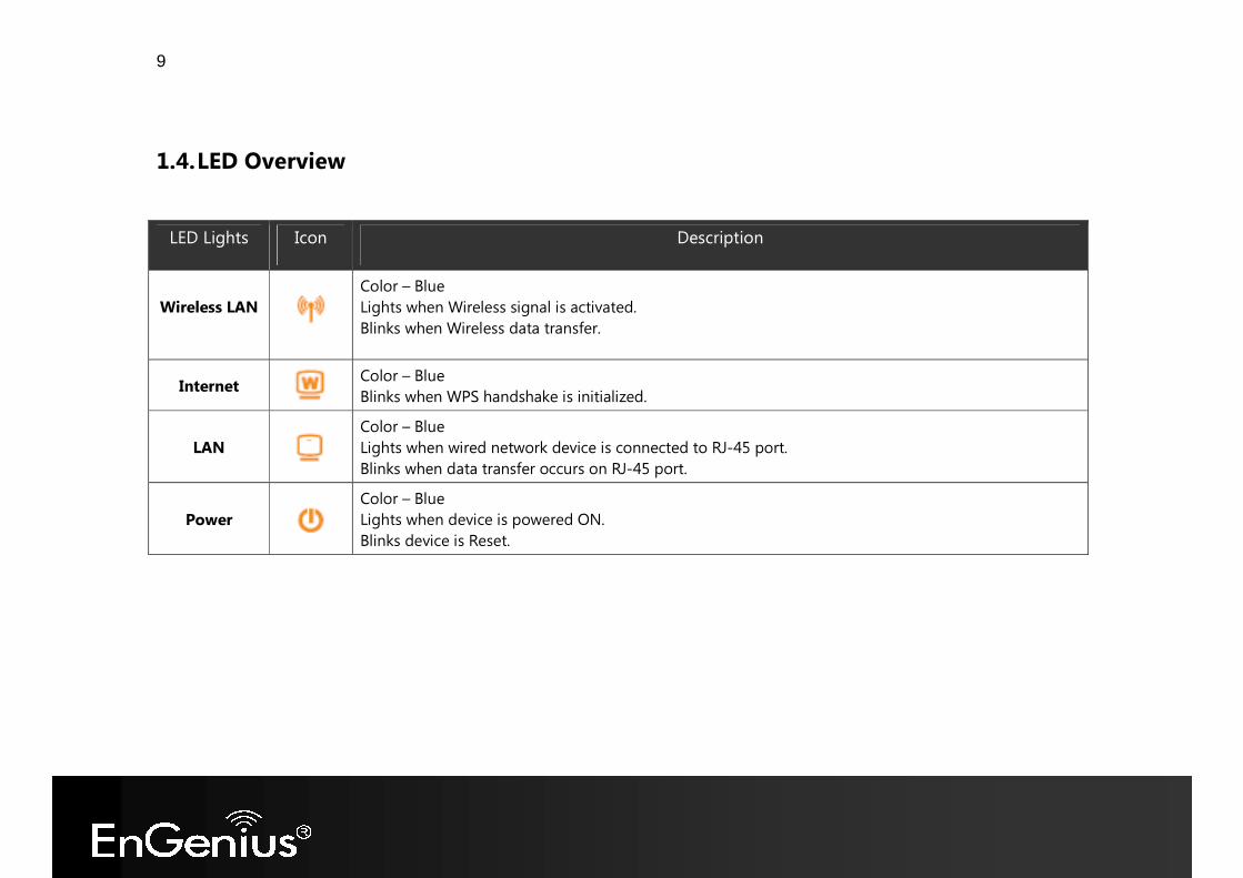
LED Lights Icon Description
Wireless LAN Color – Blue Lights when Wireless signal is activated. Blinks when Wireless data transfer.
Internet Color – Blue Blinks when WPS handshake is initialized.
LAN Color – Blue Lights when wired network device is connected to RJ-45 port. Blinks when data transfer occurs on RJ-45 port.
Power Color – Blue Lights when device is powered ON. Blinks device is Reset.
10
1.5. Before you Begin This section will guide you through the installation process. Placement of the ENGENIUS GOLD is very important to avoid poor signal reception and performance. Avoid placing the device in enclosed spaces such as a closet, cabinet or wardrobe.
1.6. Considerations for Wireless Installation The operating distance of all wireless devices cannot be pre-determined due to a number of unknown obstacles in the environment that the device is deployed. These could be the number, thickness and location of walls, ceilings or other objects that the wireless signals must pass through. Here are some key guidelines to ensure that you have the optimal wireless range. � Keep the number of walls and ceilings between the EnGenius access point and other network devices to a minimum.
Each wall or ceiling can reduce the signal strength; the degradation depends on the building’s material. � Building materials makes a difference. A solid metal door or aluminum stubs may have a significant negative effect on
range. Locate your wireless devices carefully so the signal can pass through a drywall or open doorways. Materials such as glass, steel, metal, concrete, water (fish tanks), mirrors, file cabinets and brick will also degrade your wireless signal.
� Interferences can also come from your other electrical devices or appliances that generate RF noise. The most usual
types are microwaves, or cordless phones.
11
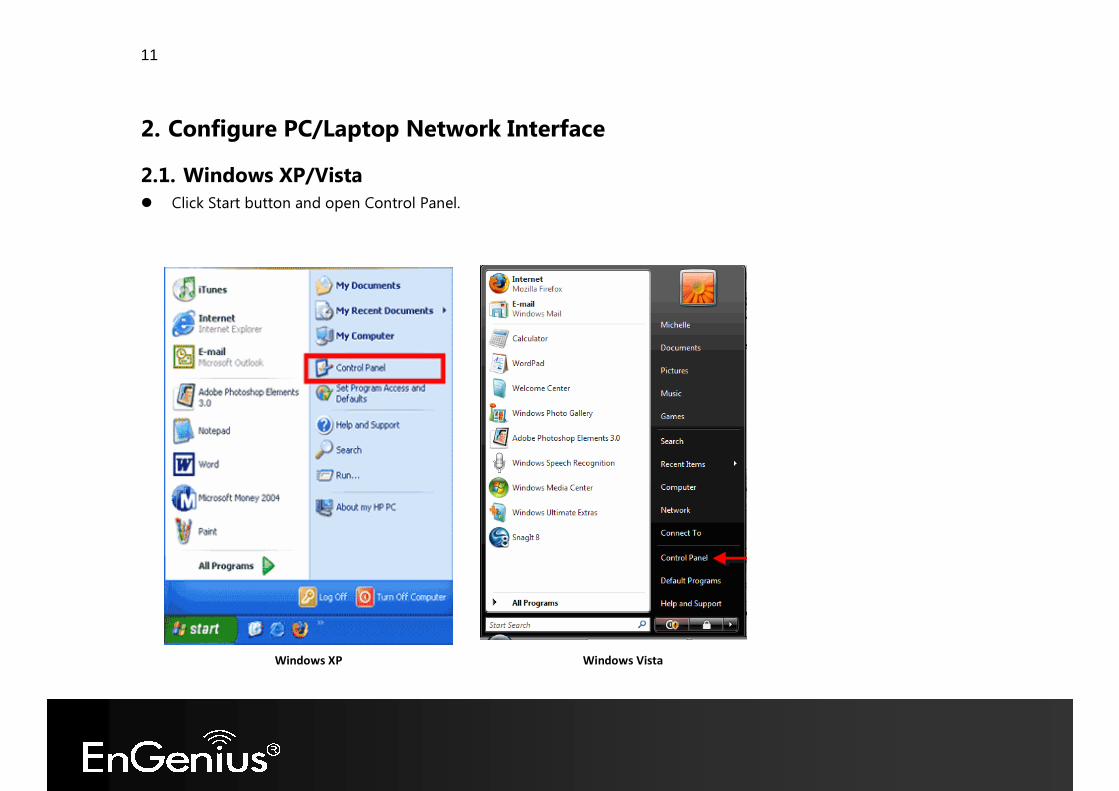
2. Configure PC/Laptop Network Interface 2.1. Windows XP/Vista � Click Start button and open Control Panel.
Windows XP Windows Vista
12
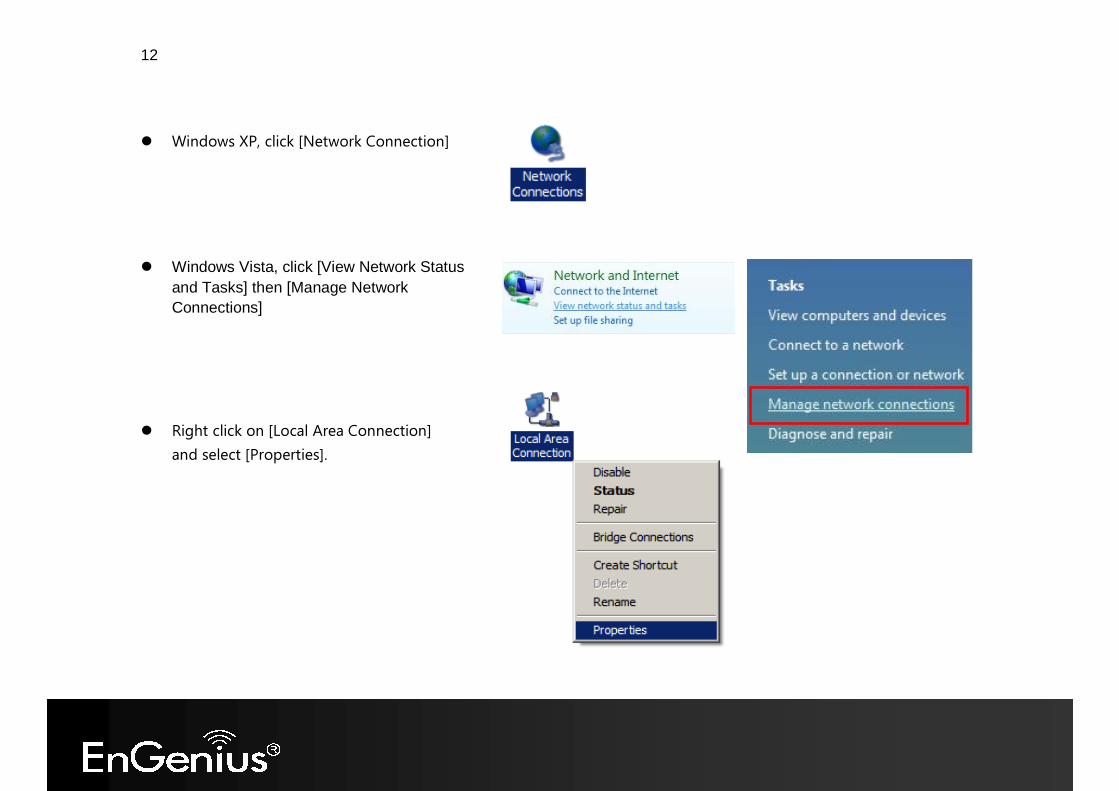
� Windows XP, click [Network Connection]
� Right click on [Local Area Connection] and select [Properties].
� Windows Vista, click [View Network Status and Tasks] then [Manage Network Connections]
13
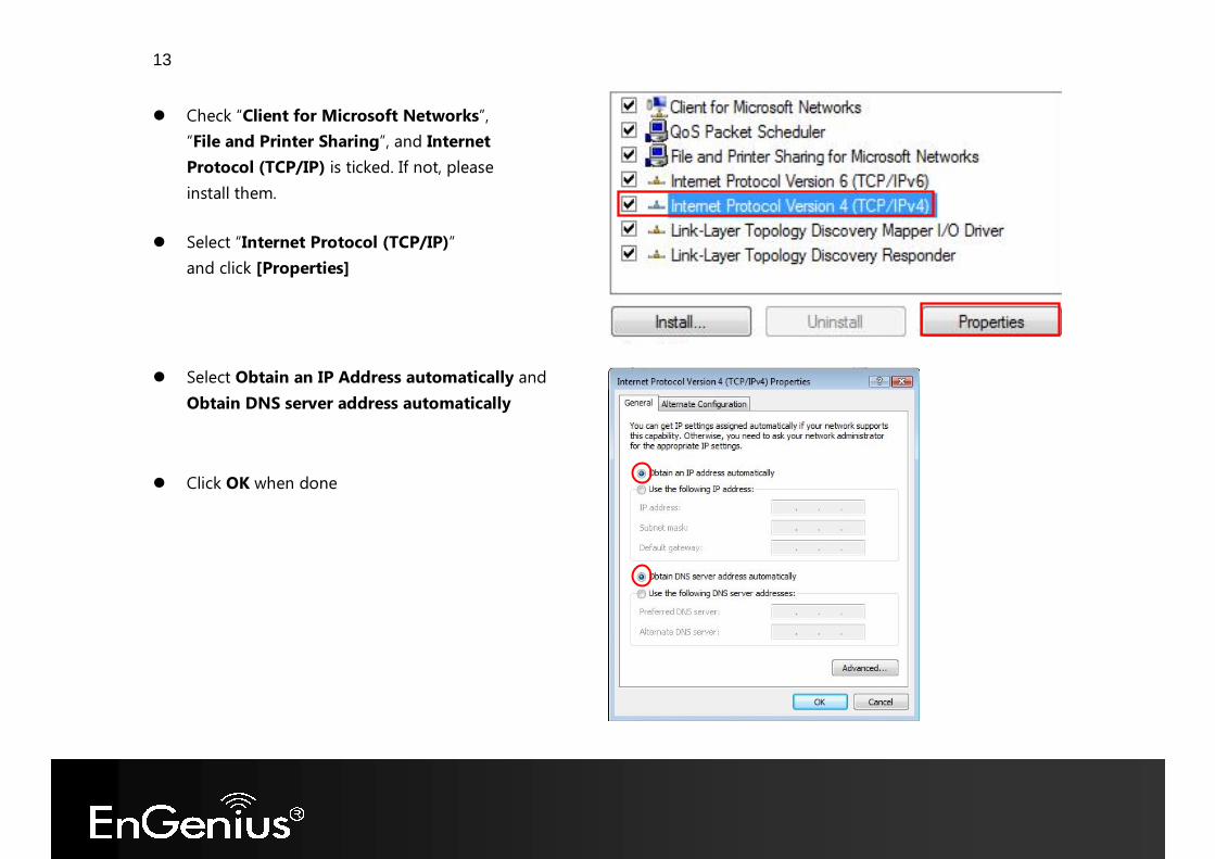
� Check “Client for Microsoft Networks”, “File and Printer Sharing”, and Internet Protocol (TCP/IP) is ticked. If not, please install them.
� Select Obtain an IP Address automatically and Obtain DNS server address automatically
� Click OK when done
� Select “Internet Protocol (TCP/IP)” and click [Properties]
14
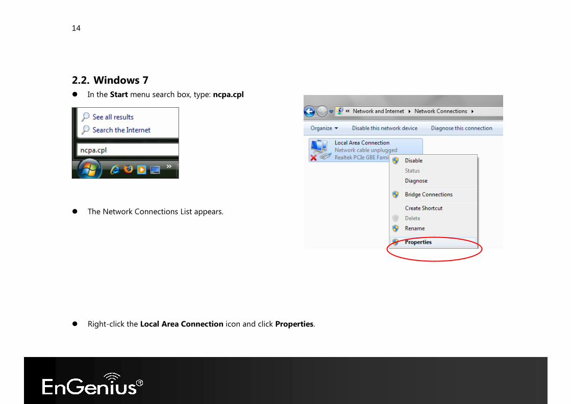
2.2. Windows 7 � In the Start menu search box, type: ncpa.cpl
� The Network Connections List appears. � Right-click the Local Area Connection icon and click Properties.
15
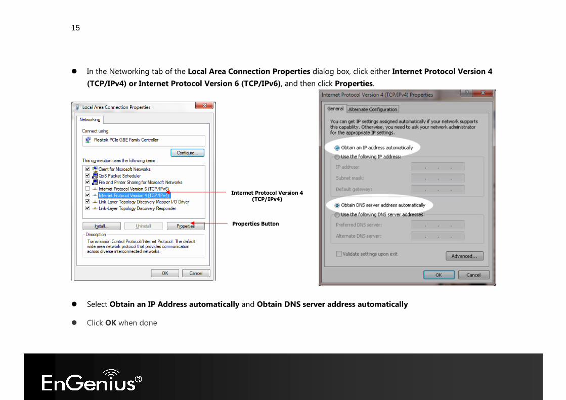
� In the Networking tab of the Local Area Connection Properties dialog box, click either Internet Protocol Version 4
(TCP/IPv4) or Internet Protocol Version 6 (TCP/IPv6), and then click Properties.
� Select Obtain an IP Address automatically and Obtain DNS server address automatically � Click OK when done
Properties Button
Internet Protocol Version 4 (TCP/IPv4)
16
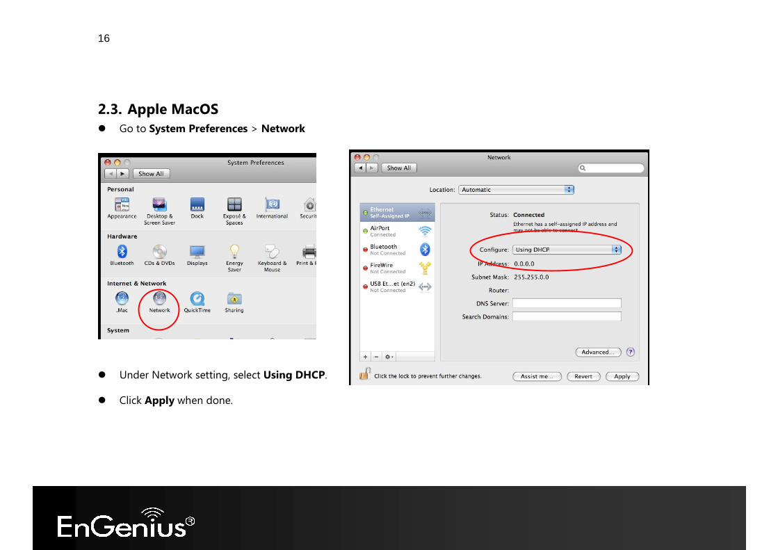
2.3. Apple MacOS � Go to System Preferences > Network
� Under Network setting, select Using DHCP. � Click Apply when done.
17
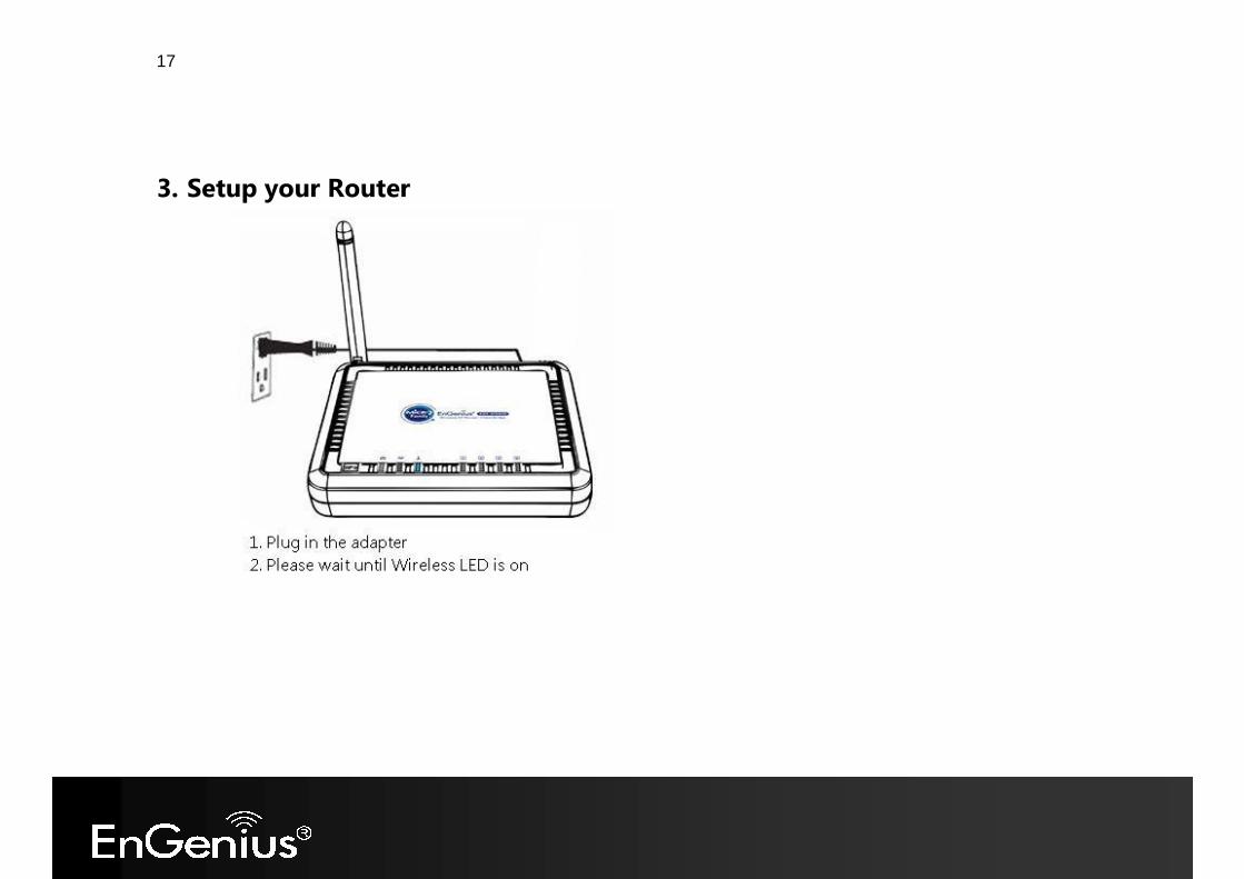
3. Setup your Router
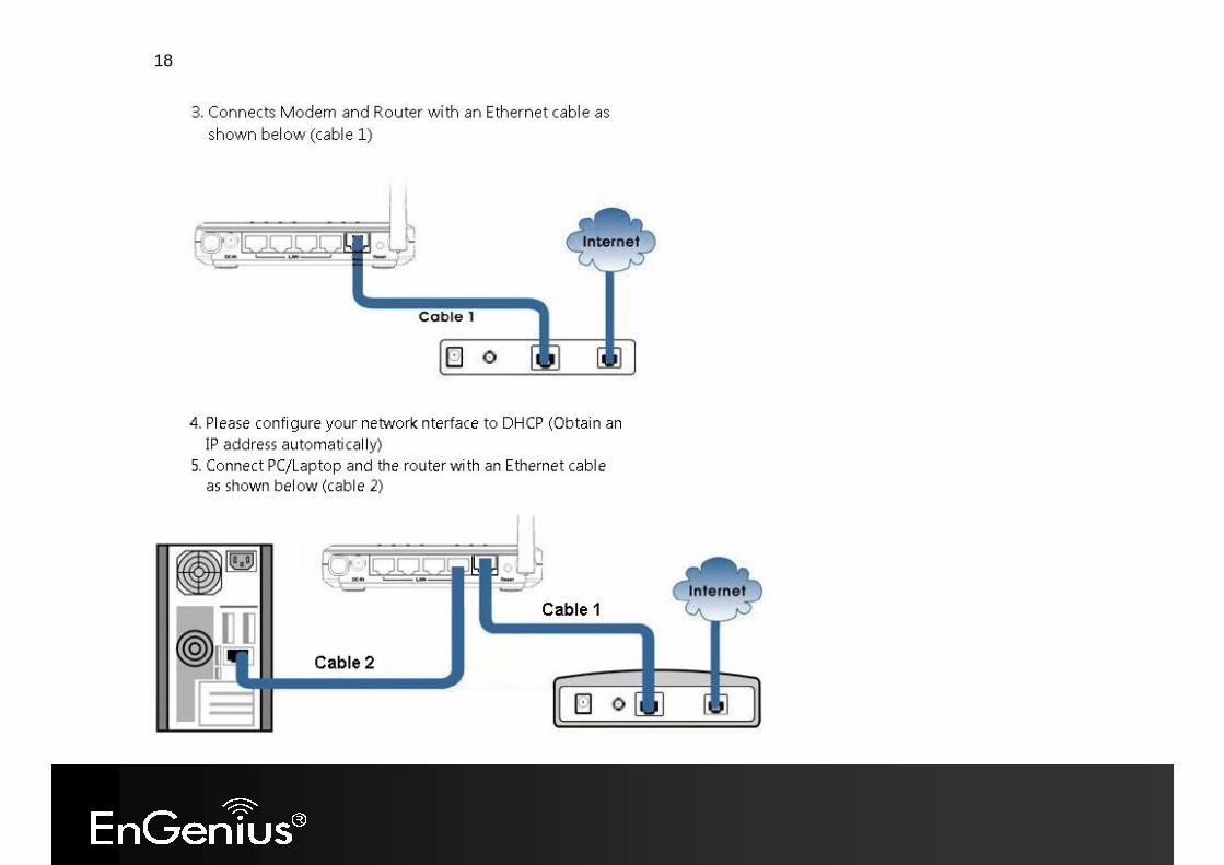
18
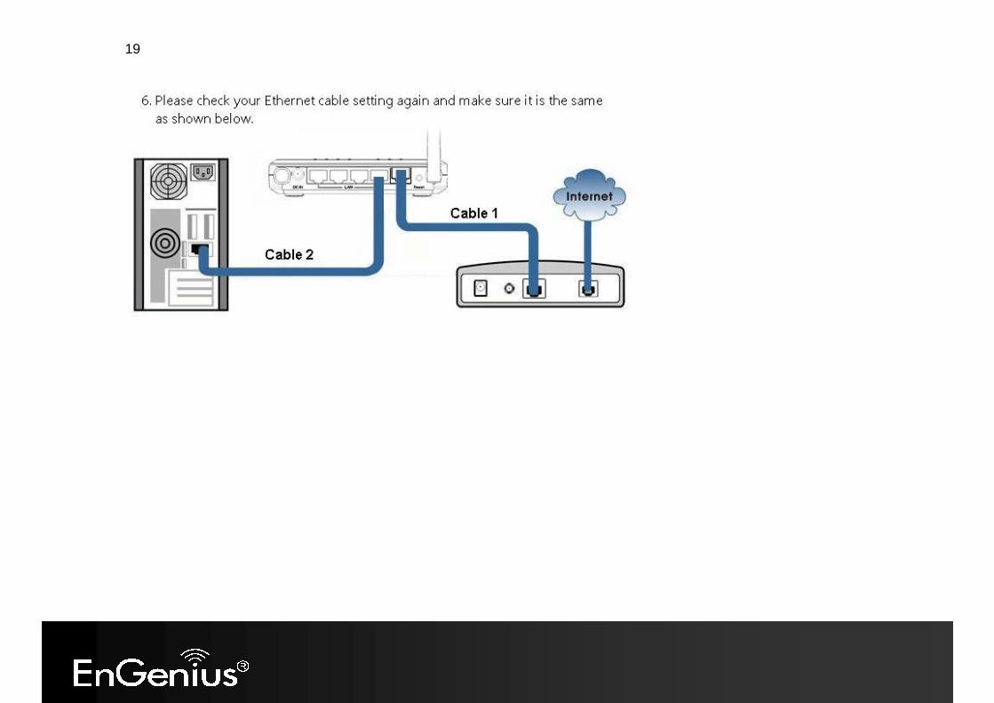
19
20
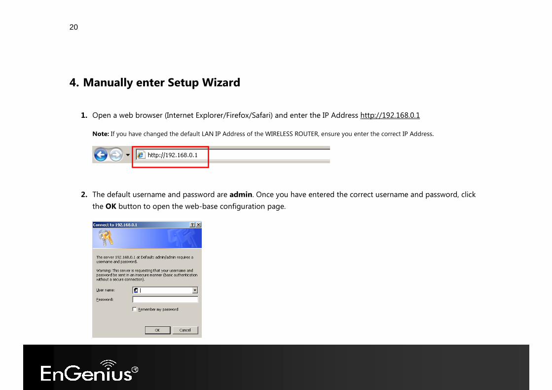
4. Manually enter Setup Wizard
1. Open a web browser (Internet Explorer/Firefox/Safari) and enter the IP Address http://192.168.0.1 Note: If you have changed the default LAN IP Address of the WIRELESS ROUTER, ensure you enter the correct IP Address.
2. The default username and password are admin. Once you have entered the correct username and password, click the OK button to open the web-base configuration page.
21
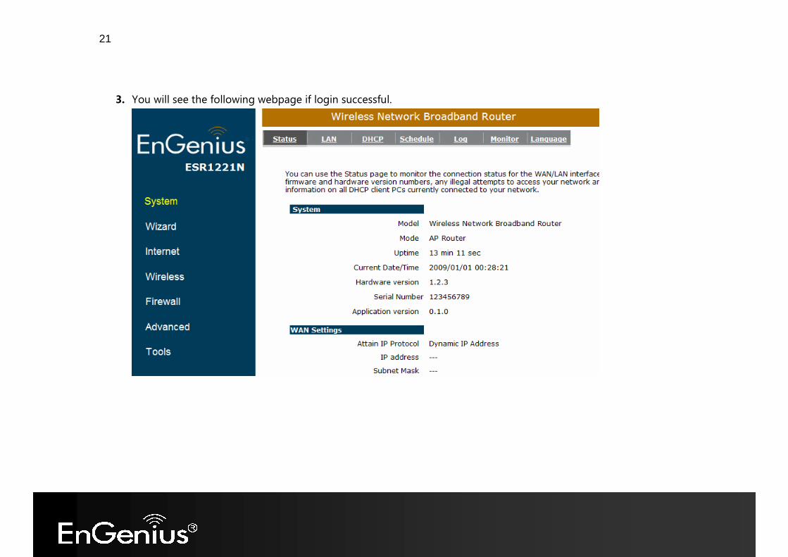
3. You will see the following webpage if login successful.
22
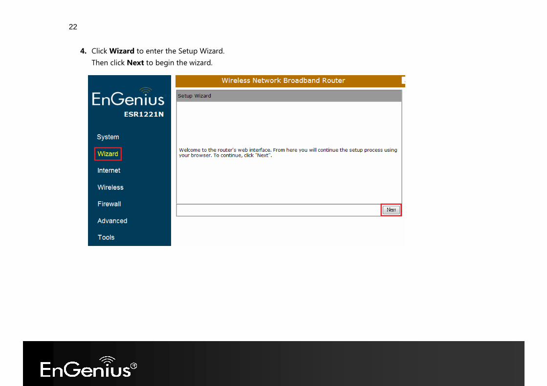
4. Click Wizard to enter the Setup Wizard. Then click Next to begin the wizard.
23
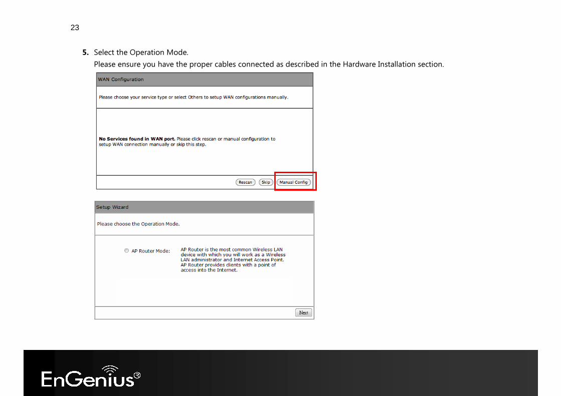
5. Select the Operation Mode. Please ensure you have the proper cables connected as described in the Hardware Installation section.
24
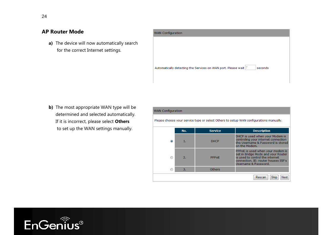
AP Router Mode
a) The device will now automatically search for the correct Internet settings.
b) The most appropriate WAN type will be
determined and selected automatically. If it is incorrect, please select Others to set up the WAN settings manually.
25
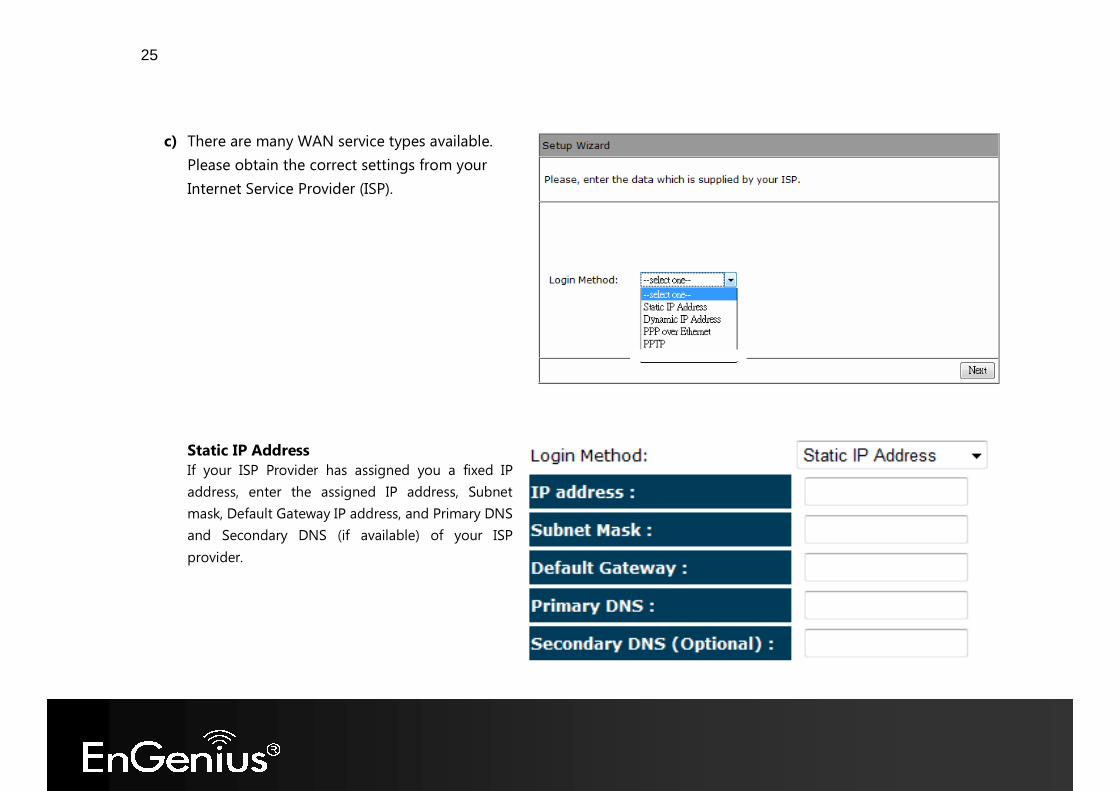
c) There are many WAN service types available.
Please obtain the correct settings from your Internet Service Provider (ISP). Static IP Address If your ISP Provider has assigned you a fixed IP address, enter the assigned IP address, Subnet mask, Default Gateway IP address, and Primary DNS and Secondary DNS (if available) of your ISP provider.
26
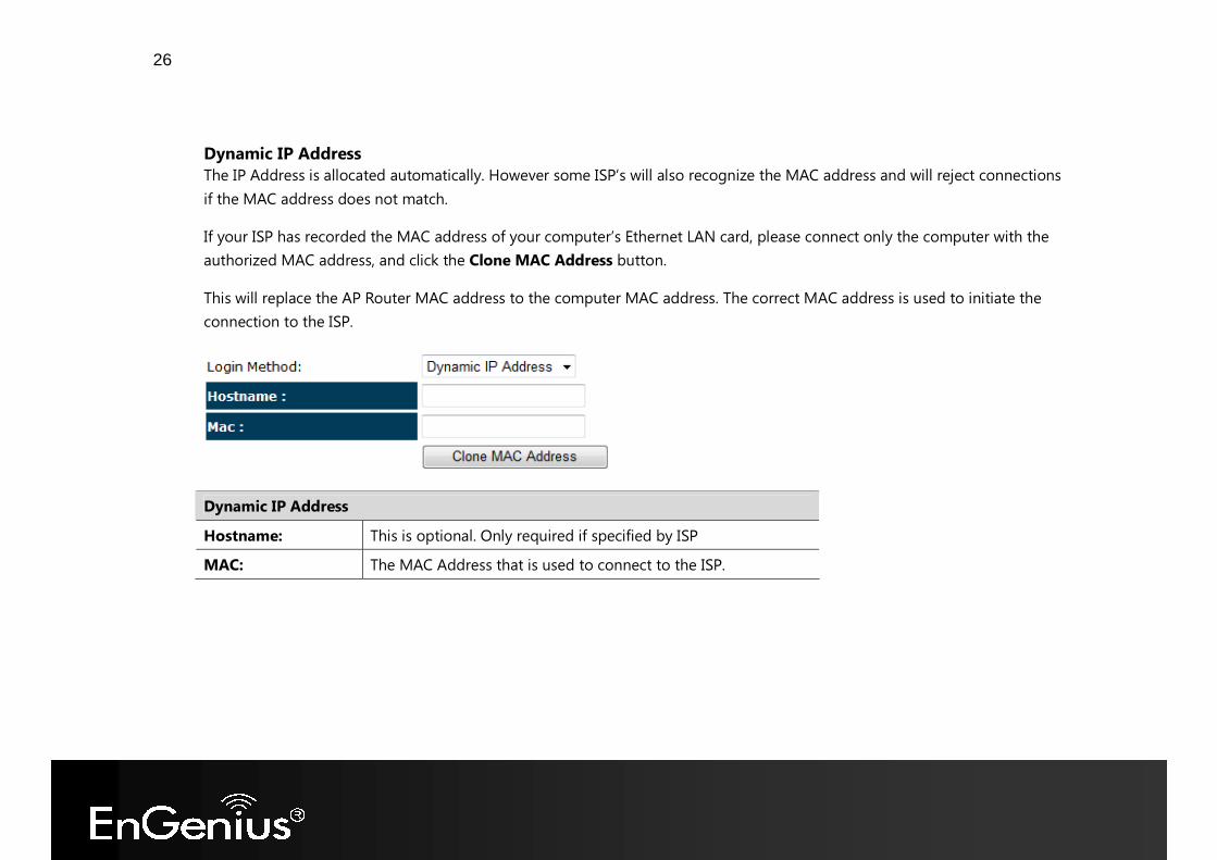
Dynamic IP Address The IP Address is allocated automatically. However some ISP’s will also recognize the MAC address and will reject connections if the MAC address does not match. If your ISP has recorded the MAC address of your computer’s Ethernet LAN card, please connect only the computer with the authorized MAC address, and click the Clone MAC Address button. This will replace the AP Router MAC address to the computer MAC address. The correct MAC address is used to initiate the connection to the ISP.
Dynamic IP Address Hostname: This is optional. Only required if specified by ISP MAC: The MAC Address that is used to connect to the ISP.
27
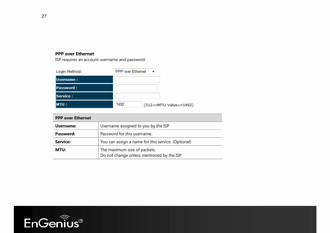
PPP over Ethernet ISP requires an account username and password.
PPP over Ethernet Username: Username assigned to you by the ISP Password: Password for this username. Service: You can assign a name for this service. (Optional) MTU: The maximum size of packets.
Do not change unless mentioned by the ISP.
28
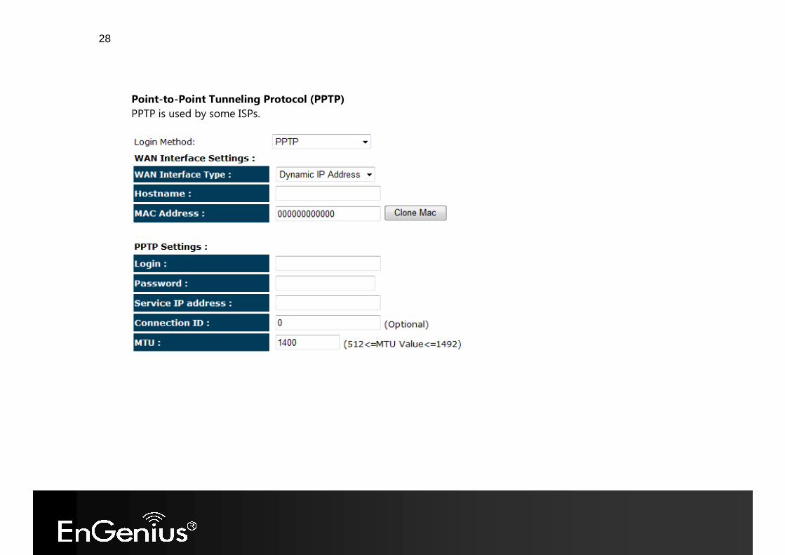
Point-to-Point Tunneling Protocol (PPTP) PPTP is used by some ISPs.
29
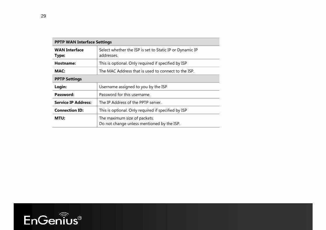
PPTP WAN Interface Settings WAN Interface Type:
Select whether the ISP is set to Static IP or Dynamic IP addresses.
Hostname: This is optional. Only required if specified by ISP MAC: The MAC Address that is used to connect to the ISP. PPTP Settings Login: Username assigned to you by the ISP Password: Password for this username. Service IP Address: The IP Address of the PPTP server. Connection ID: This is optional. Only required if specified by ISP MTU: The maximum size of packets.
Do not change unless mentioned by the ISP.
30
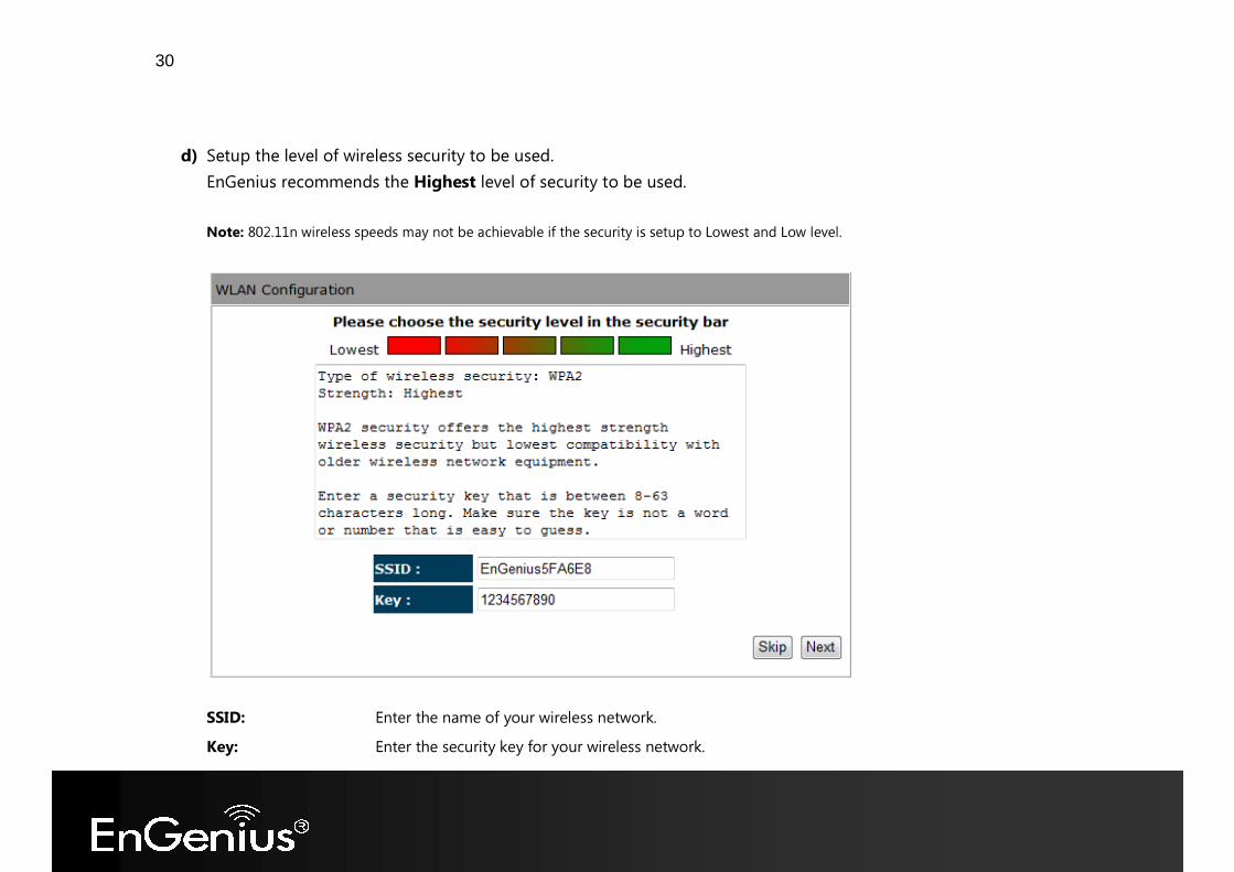
d) Setup the level of wireless security to be used.
EnGenius recommends the Highest level of security to be used. Note: 802.11n wireless speeds may not be achievable if the security is setup to Lowest and Low level.
SSID: Enter the name of your wireless network. Key: Enter the security key for your wireless network.
31
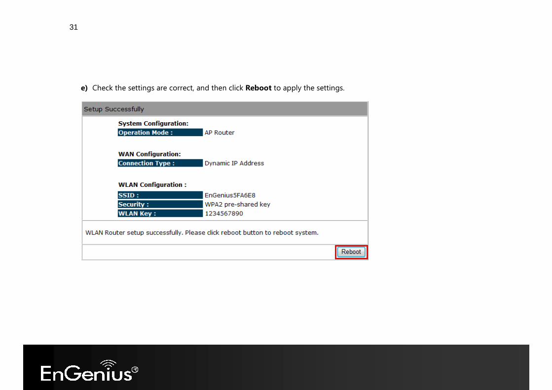
e) Check the settings are correct, and then click Reboot to apply the settings.
32
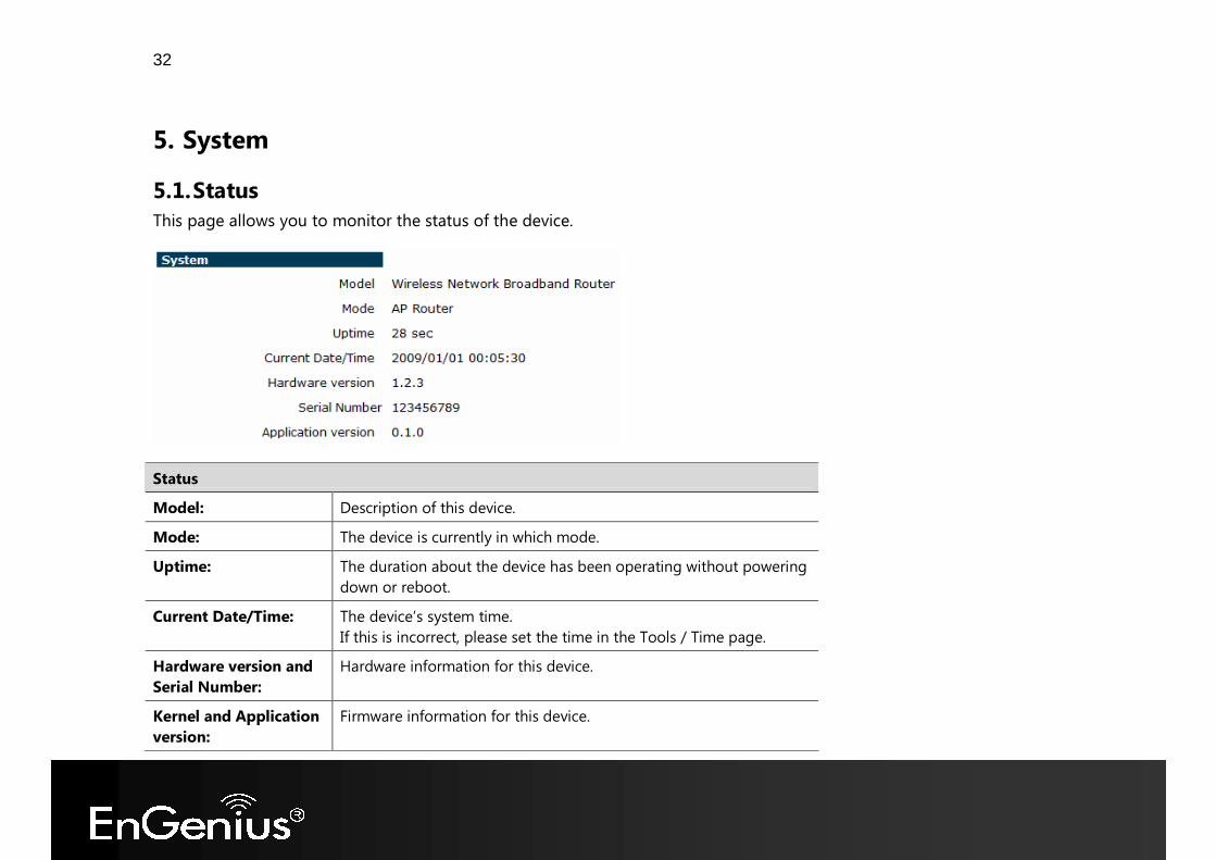
5. System 5.1. Status This page allows you to monitor the status of the device.
Status Model: Description of this device. Mode: The device is currently in which mode. Uptime: The duration about the device has been operating without powering
down or reboot. Current Date/Time: The device’s system time.
If this is incorrect, please set the time in the Tools / Time page. Hardware version and Serial Number:
Hardware information for this device.
Kernel and Application version:
Firmware information for this device.
33
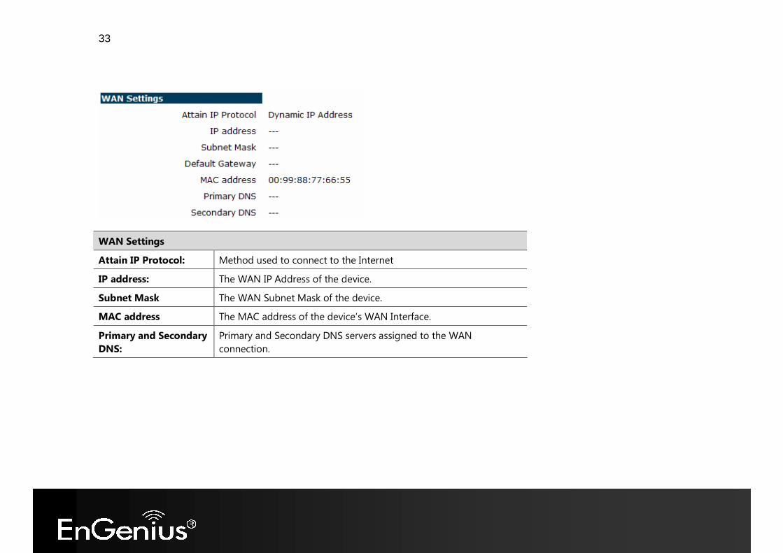
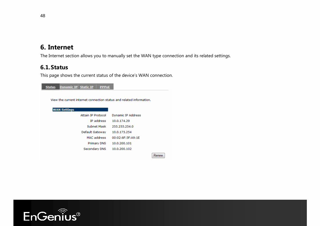
WAN Settings Attain IP Protocol: Method used to connect to the Internet IP address: The WAN IP Address of the device. Subnet Mask The WAN Subnet Mask of the device. MAC address The MAC address of the device’s WAN Interface. Primary and Secondary DNS:
Primary and Secondary DNS servers assigned to the WAN connection.
34
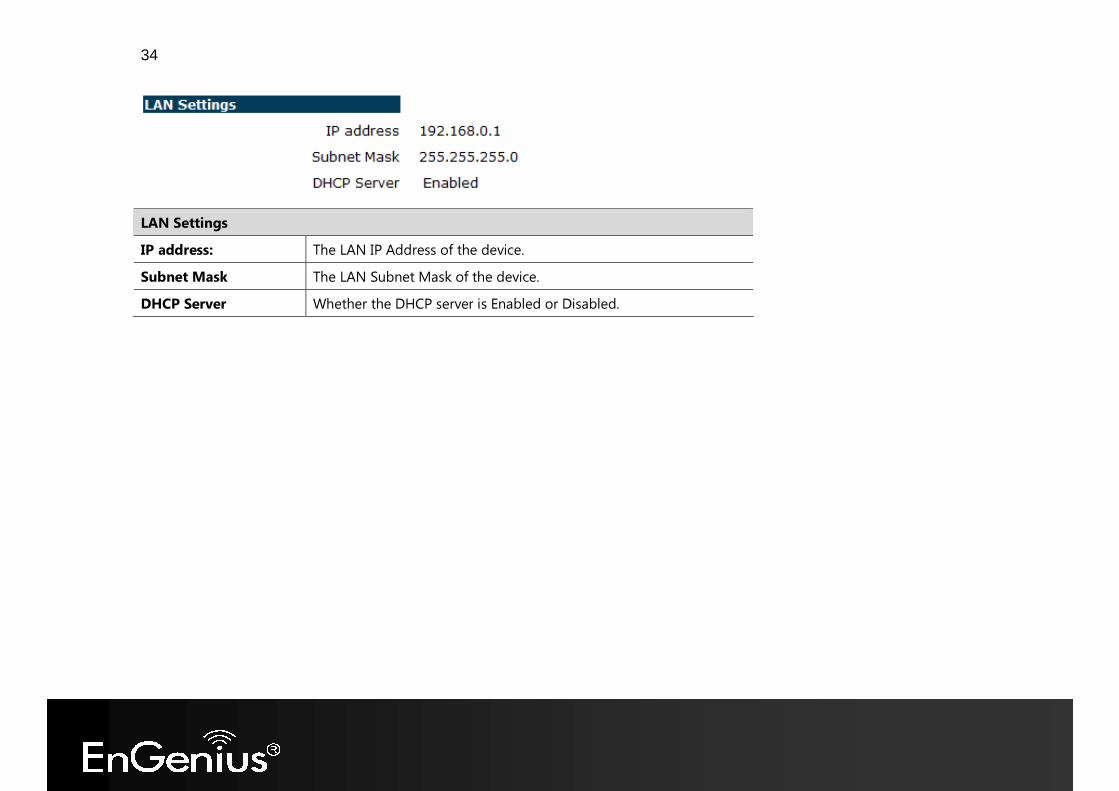
LAN Settings IP address: The LAN IP Address of the device. Subnet Mask The LAN Subnet Mask of the device. DHCP Server Whether the DHCP server is Enabled or Disabled.
35
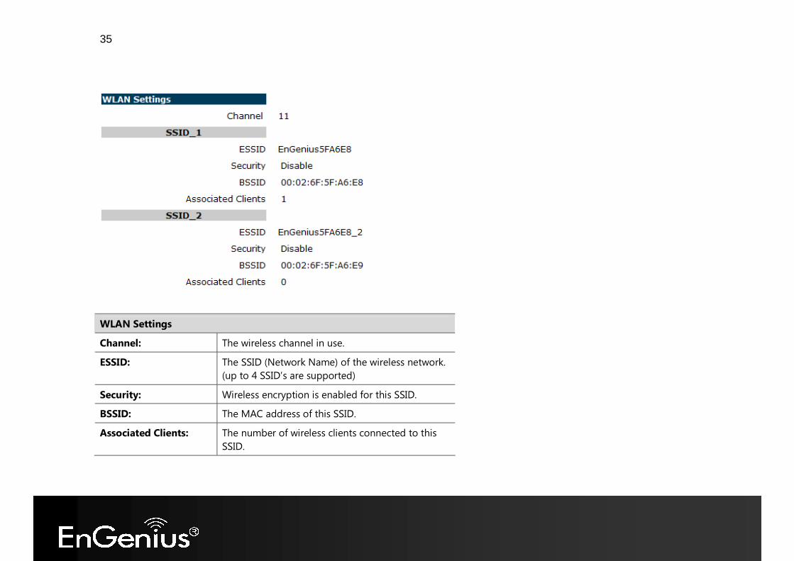
WLAN Settings Channel: The wireless channel in use. ESSID: The SSID (Network Name) of the wireless network.
(up to 4 SSID’s are supported) Security: Wireless encryption is enabled for this SSID. BSSID: The MAC address of this SSID. Associated Clients: The number of wireless clients connected to this
SSID.
36
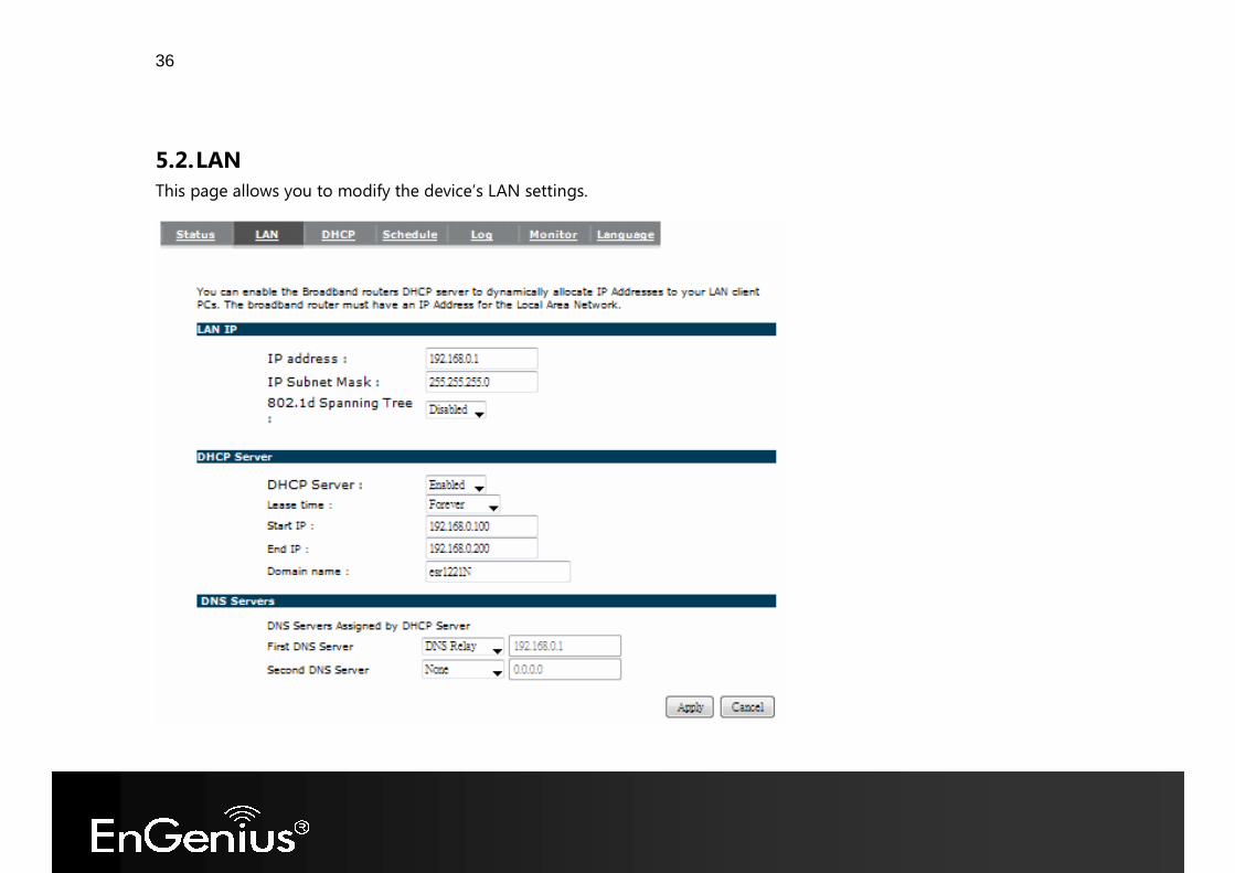
5.2. LAN This page allows you to modify the device’s LAN settings.
37
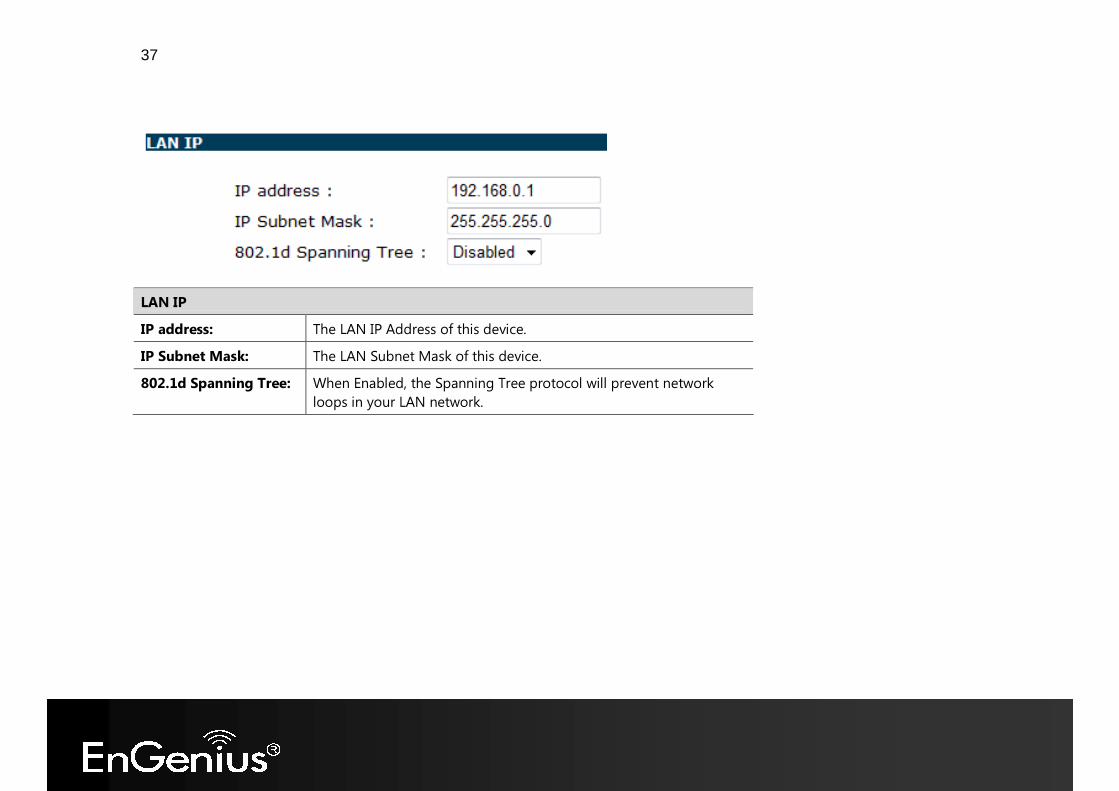
LAN IP IP address: The LAN IP Address of this device. IP Subnet Mask: The LAN Subnet Mask of this device. 802.1d Spanning Tree: When Enabled, the Spanning Tree protocol will prevent network
loops in your LAN network.
38
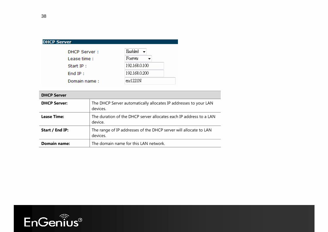
DHCP Server DHCP Server: The DHCP Server automatically allocates IP addresses to your LAN
devices. Lease Time: The duration of the DHCP server allocates each IP address to a LAN
device. Start / End IP: The range of IP addresses of the DHCP server will allocate to LAN
devices. Domain name: The domain name for this LAN network.
39
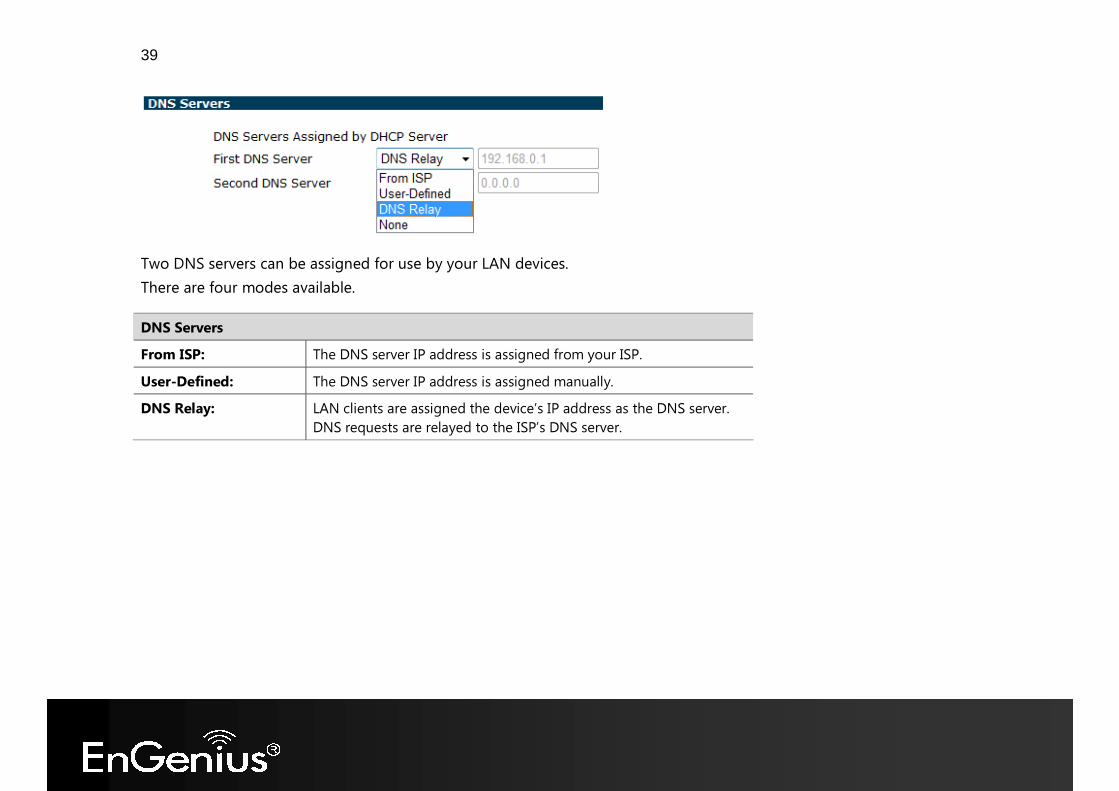
Two DNS servers can be assigned for use by your LAN devices. There are four modes available.
DNS Servers From ISP: The DNS server IP address is assigned from your ISP. User-Defined: The DNS server IP address is assigned manually. DNS Relay: LAN clients are assigned the device’s IP address as the DNS server.
DNS requests are relayed to the ISP’s DNS server.
40
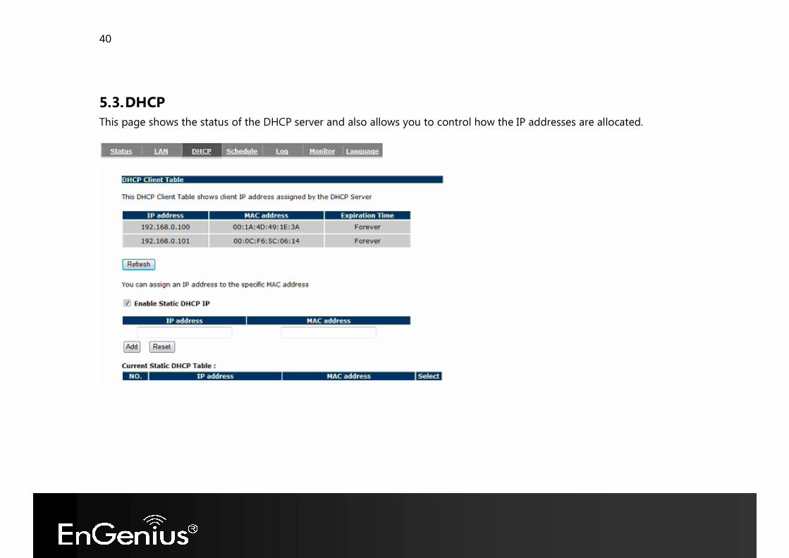
5.3. DHCP This page shows the status of the DHCP server and also allows you to control how the IP addresses are allocated.
41
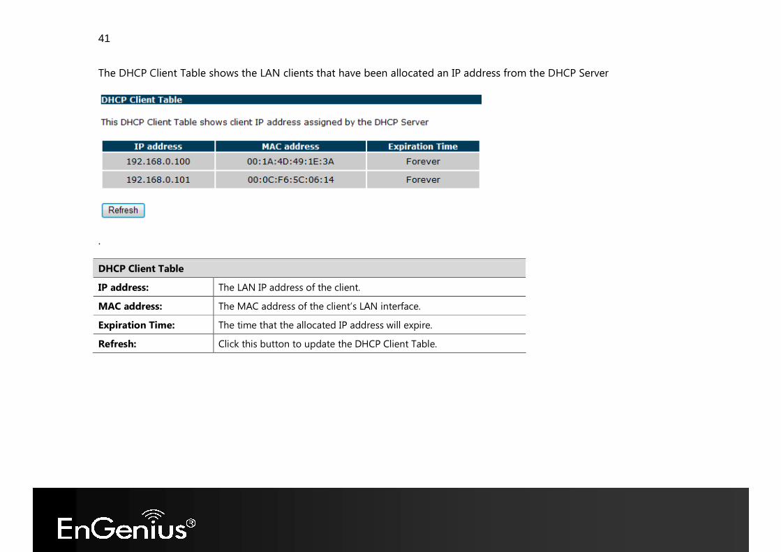
The DHCP Client Table shows the LAN clients that have been allocated an IP address from the DHCP Server
.
DHCP Client Table IP address: The LAN IP address of the client. MAC address: The MAC address of the client’s LAN interface. Expiration Time: The time that the allocated IP address will expire. Refresh: Click this button to update the DHCP Client Table.
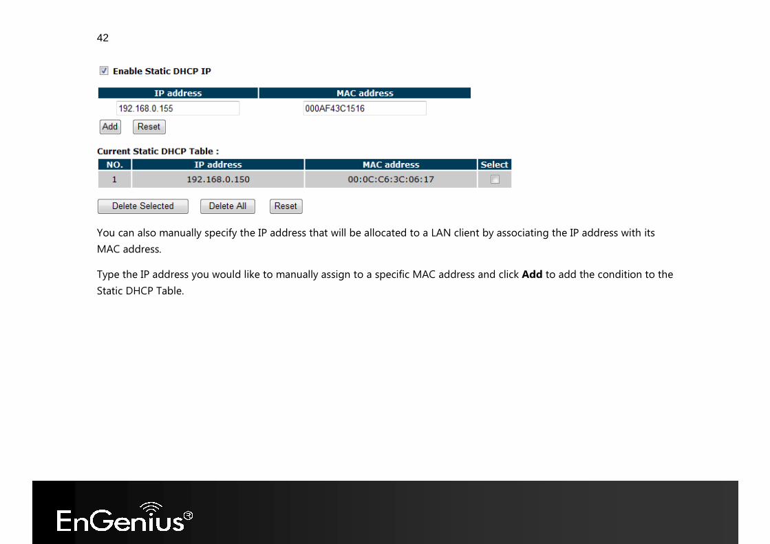
42
You can also manually specify the IP address that will be allocated to a LAN client by associating the IP address with its MAC address. Type the IP address you would like to manually assign to a specific MAC address and click Add to add the condition to the Static DHCP Table.
43
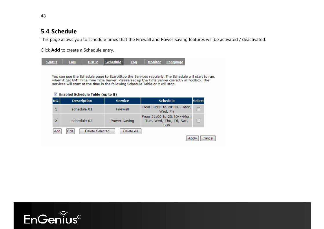
5.4. Schedule This page allows you to schedule times that the Firewall and Power Saving features will be activated / deactivated. Click Add to create a Schedule entry.
44
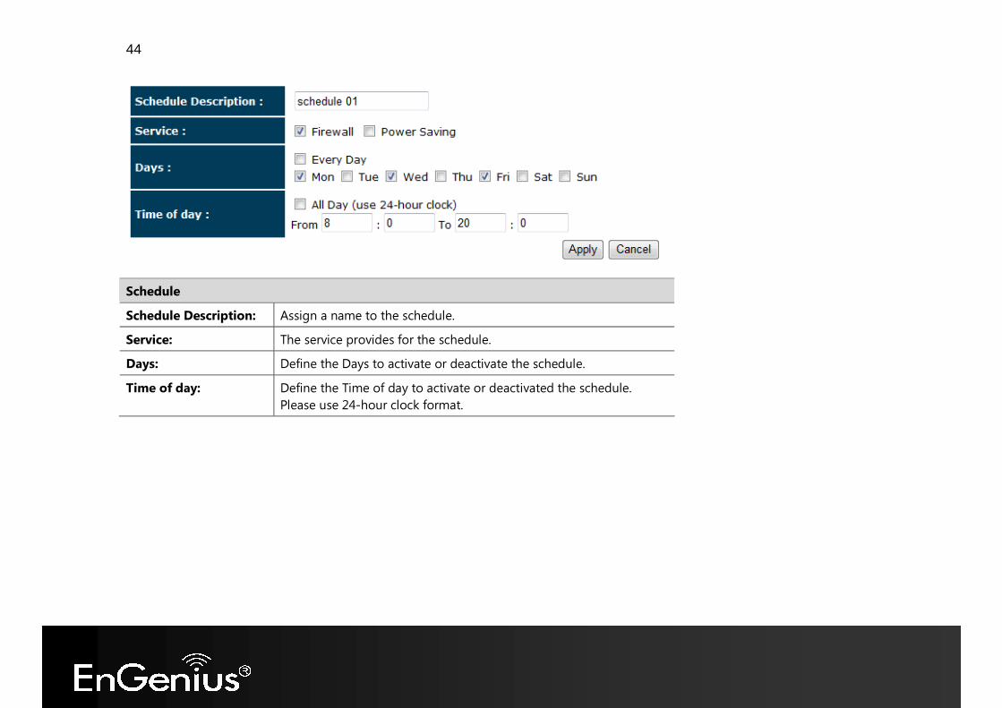
Schedule Schedule Description: Assign a name to the schedule. Service: The service provides for the schedule. Days: Define the Days to activate or deactivate the schedule. Time of day: Define the Time of day to activate or deactivated the schedule.
Please use 24-hour clock format.
45
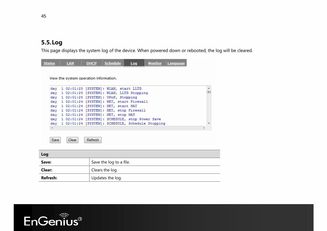
5.5. Log This page displays the system log of the device. When powered down or rebooted, the log will be cleared.
Log Save: Save the log to a file. Clear: Clears the log. Refresh: Updates the log.
46
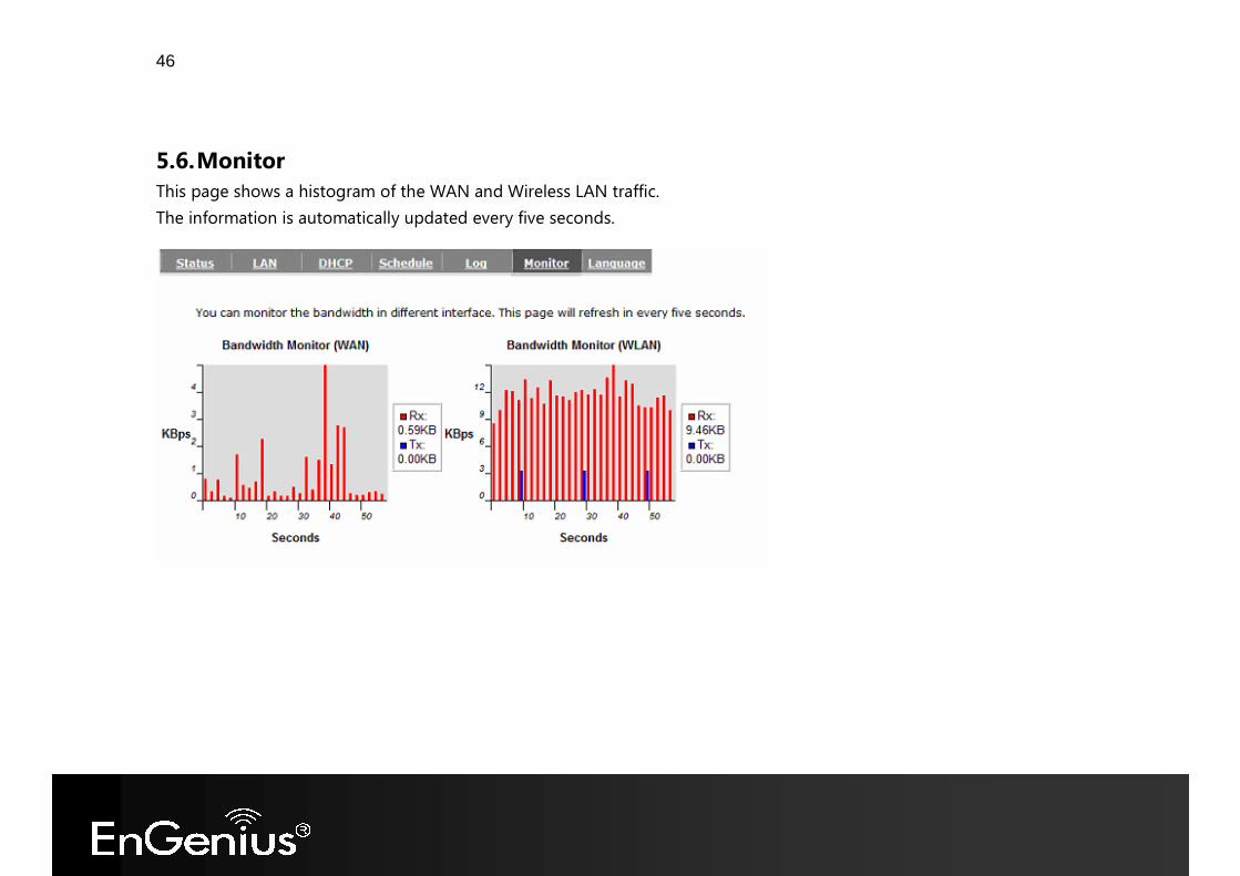
5.6. Monitor This page shows a histogram of the WAN and Wireless LAN traffic. The information is automatically updated every five seconds.
47
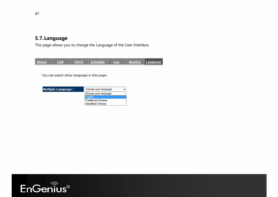
5.7. Language This page allows you to change the Language of the User Interface.
48
6. Internet The Internet section allows you to manually set the WAN type connection and its related settings.
6.1. Status This page shows the current status of the device’s WAN connection.
49
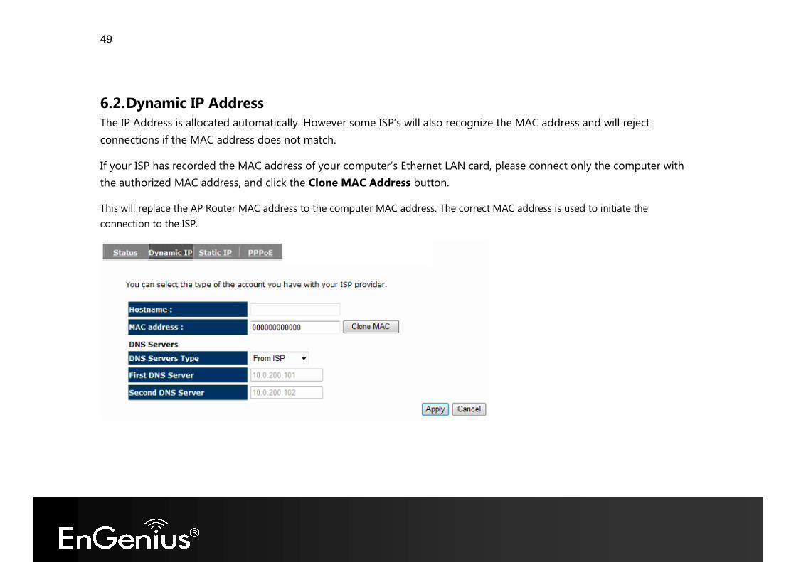
6.2. Dynamic IP Address The IP Address is allocated automatically. However some ISP’s will also recognize the MAC address and will reject connections if the MAC address does not match. If your ISP has recorded the MAC address of your computer’s Ethernet LAN card, please connect only the computer with the authorized MAC address, and click the Clone MAC Address button. This will replace the AP Router MAC address to the computer MAC address. The correct MAC address is used to initiate the connection to the ISP.
50
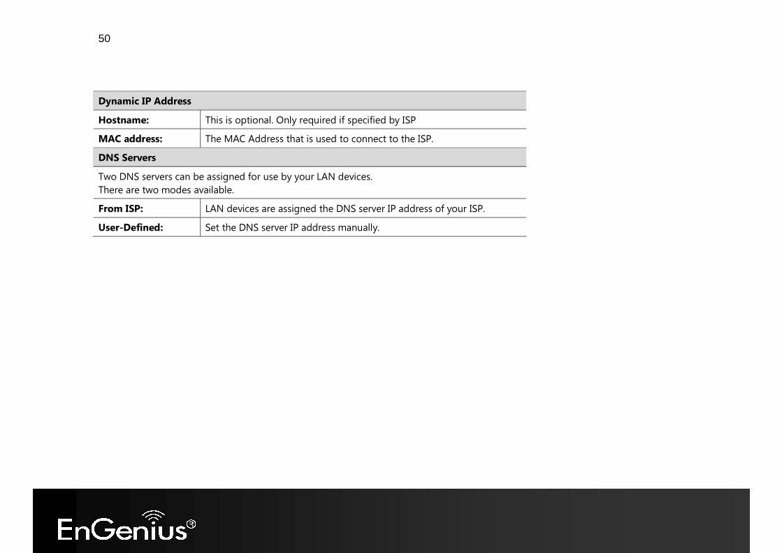
Dynamic IP Address Hostname: This is optional. Only required if specified by ISP MAC address: The MAC Address that is used to connect to the ISP. DNS Servers Two DNS servers can be assigned for use by your LAN devices. There are two modes available. From ISP: LAN devices are assigned the DNS server IP address of your ISP. User-Defined: Set the DNS server IP address manually.
51
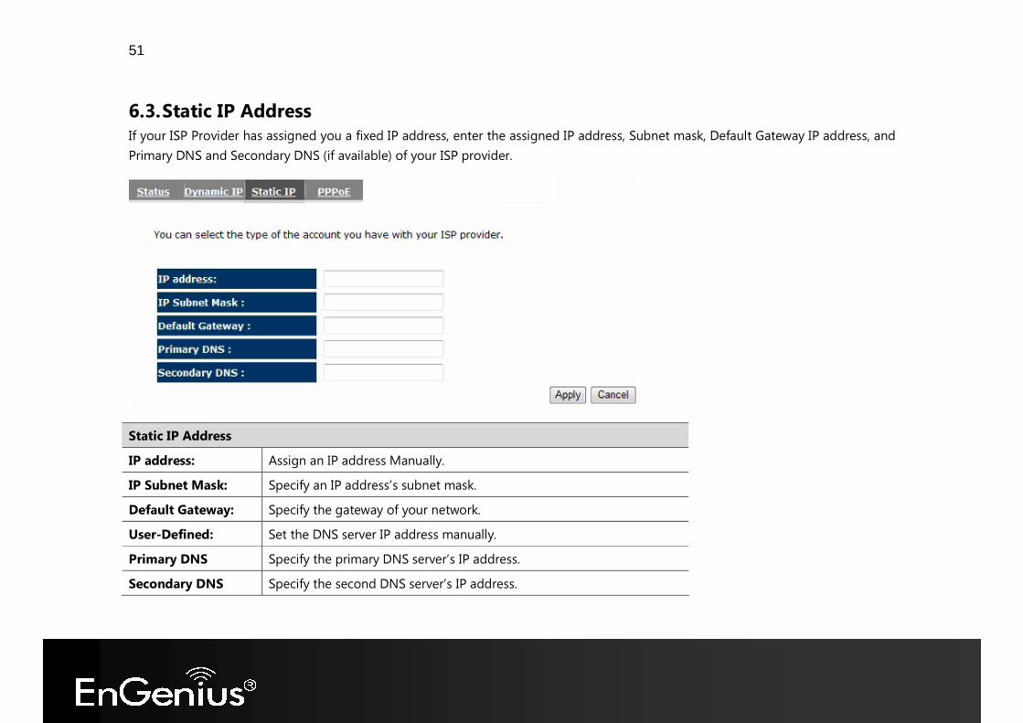
6.3. Static IP Address If your ISP Provider has assigned you a fixed IP address, enter the assigned IP address, Subnet mask, Default Gateway IP address, and Primary DNS and Secondary DNS (if available) of your ISP provider.
Static IP Address IP address: Assign an IP address Manually. IP Subnet Mask: Specify an IP address’s subnet mask. Default Gateway: Specify the gateway of your network. User-Defined: Set the DNS server IP address manually. Primary DNS Specify the primary DNS server’s IP address. Secondary DNS Specify the second DNS server’s IP address.
52
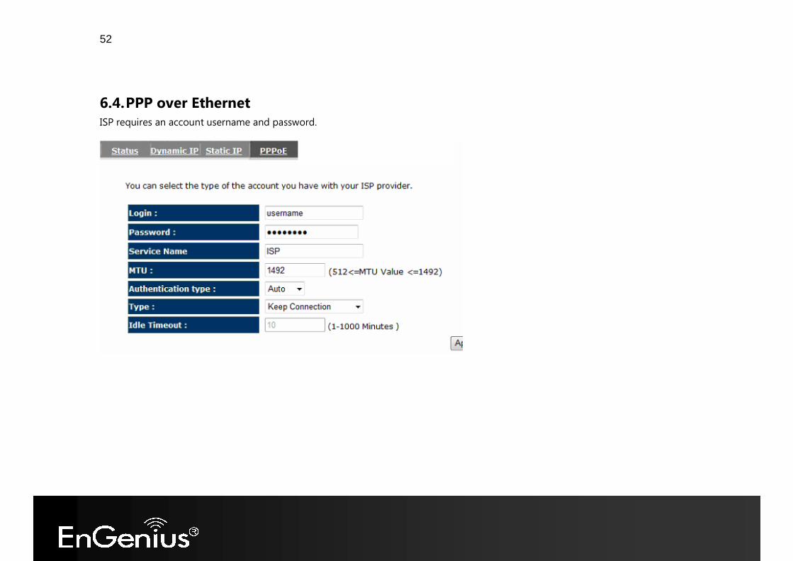
6.4. PPP over Ethernet ISP requires an account username and password.
53
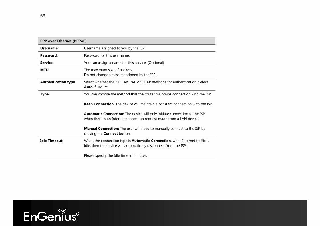
PPP over Ethernet (PPPoE) Username: Username assigned to you by the ISP Password: Password for this username. Service: You can assign a name for this service. (Optional) MTU: The maximum size of packets.
Do not change unless mentioned by the ISP. Authentication type Select whether the ISP uses PAP or CHAP methods for authentication. Select
Auto if unsure. Type: You can choose the method that the router maintains connection with the ISP.
Keep Connection: The device will maintain a constant connection with the ISP. Automatic Connection: The device will only initiate connection to the ISP when there is an Internet connection request made from a LAN device. Manual Connection: The user will need to manually connect to the ISP by clicking the Connect button.
Idle Timeout: When the connection type is Automatic Connection, when Internet traffic is idle, then the device will automatically disconnect from the ISP. Please specify the Idle time in minutes.
54
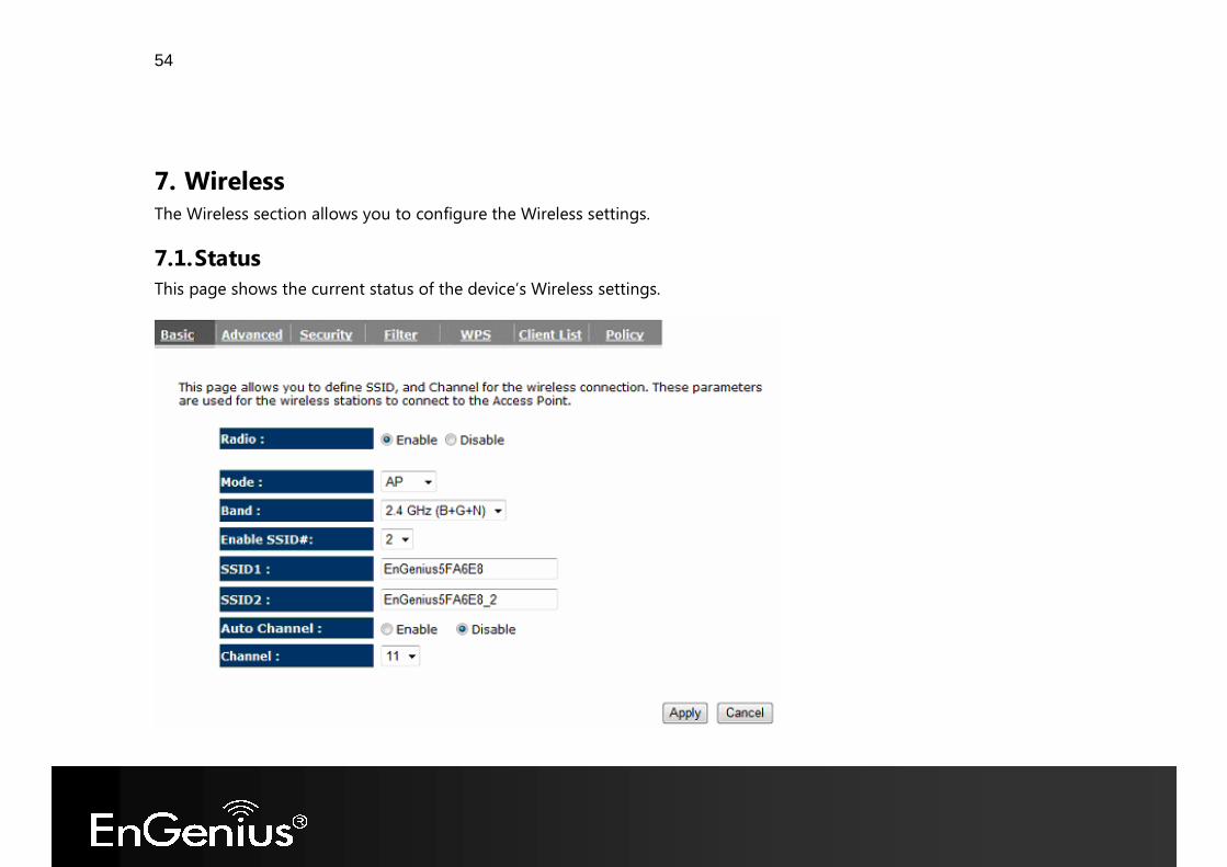
7. Wireless The Wireless section allows you to configure the Wireless settings.
7.1. Status This page shows the current status of the device’s Wireless settings.
55
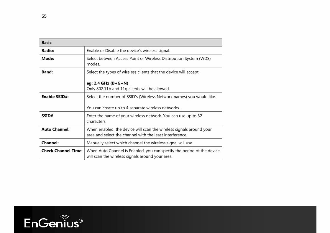
Basic Radio: Enable or Disable the device’s wireless signal. Mode: Select between Access Point or Wireless Distribution System (WDS)
modes. Band: Select the types of wireless clients that the device will accept.
eg: 2.4 GHz (B+G+N) Only 802.11b and 11g clients will be allowed.
Enable SSID#: Select the number of SSID’s (Wireless Network names) you would like. You can create up to 4 separate wireless networks.
SSID# Enter the name of your wireless network. You can use up to 32 characters.
Auto Channel: When enabled, the device will scan the wireless signals around your area and select the channel with the least interference.
Channel: Manually select which channel the wireless signal will use. Check Channel Time: When Auto Channel is Enabled, you can specify the period of the device
will scan the wireless signals around your area.
56
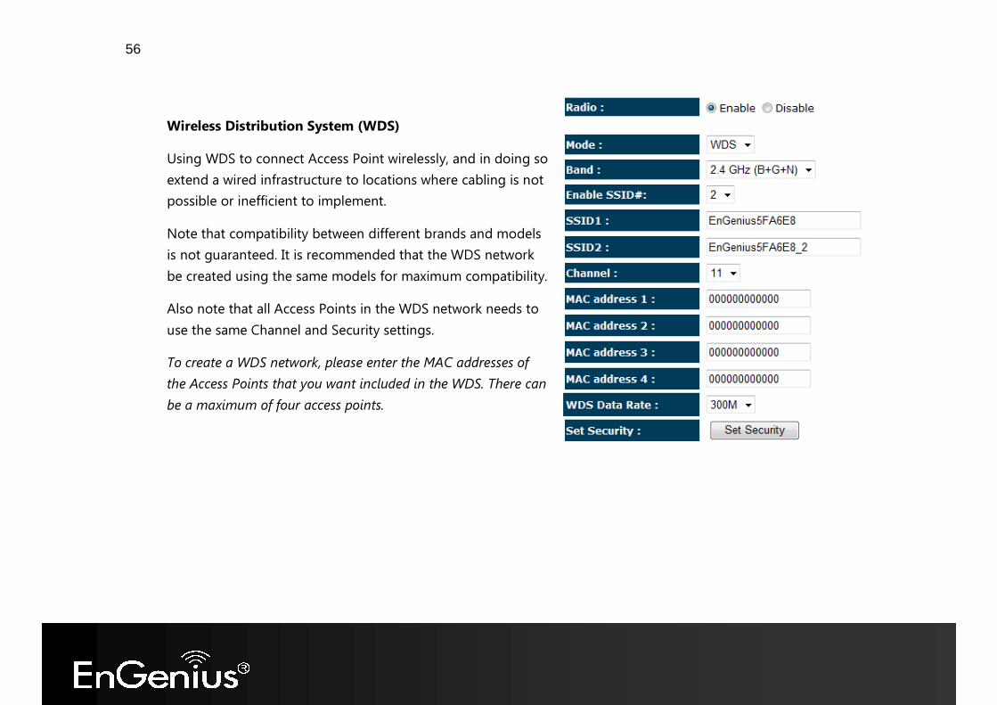
Wireless Distribution System (WDS) Using WDS to connect Access Point wirelessly, and in doing so extend a wired infrastructure to locations where cabling is not possible or inefficient to implement. Note that compatibility between different brands and models is not guaranteed. It is recommended that the WDS network be created using the same models for maximum compatibility. Also note that all Access Points in the WDS network needs to use the same Channel and Security settings. To create a WDS network, please enter the MAC addresses of the Access Points that you want included in the WDS. There can be a maximum of four access points.
57
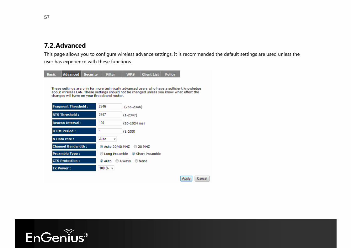
7.2. Advanced This page allows you to configure wireless advance settings. It is recommended the default settings are used unless the user has experience with these functions.
58
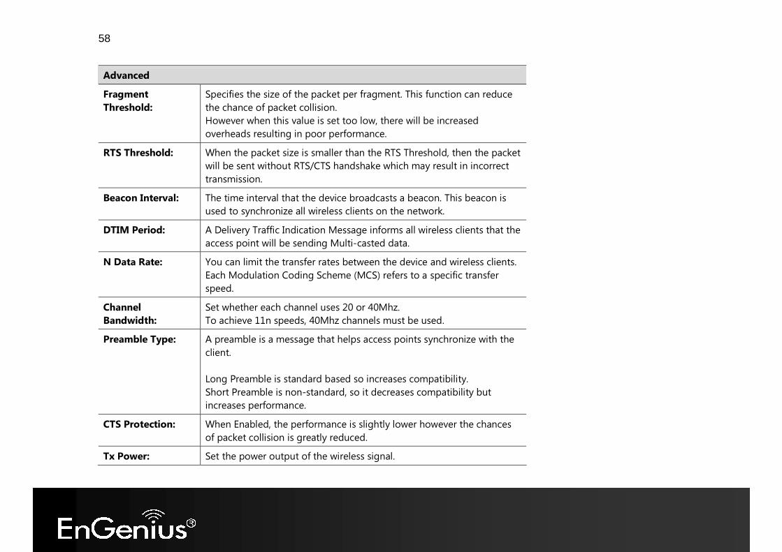
Advanced Fragment Threshold:
Specifies the size of the packet per fragment. This function can reduce the chance of packet collision. However when this value is set too low, there will be increased overheads resulting in poor performance.
RTS Threshold: When the packet size is smaller than the RTS Threshold, then the packet will be sent without RTS/CTS handshake which may result in incorrect transmission.
Beacon Interval: The time interval that the device broadcasts a beacon. This beacon is used to synchronize all wireless clients on the network.
DTIM Period: A Delivery Traffic Indication Message informs all wireless clients that the access point will be sending Multi-casted data.
N Data Rate: You can limit the transfer rates between the device and wireless clients. Each Modulation Coding Scheme (MCS) refers to a specific transfer speed.
Channel Bandwidth:
Set whether each channel uses 20 or 40Mhz. To achieve 11n speeds, 40Mhz channels must be used.
Preamble Type: A preamble is a message that helps access points synchronize with the client. Long Preamble is standard based so increases compatibility. Short Preamble is non-standard, so it decreases compatibility but increases performance.
CTS Protection: When Enabled, the performance is slightly lower however the chances of packet collision is greatly reduced.
Tx Power: Set the power output of the wireless signal.
59
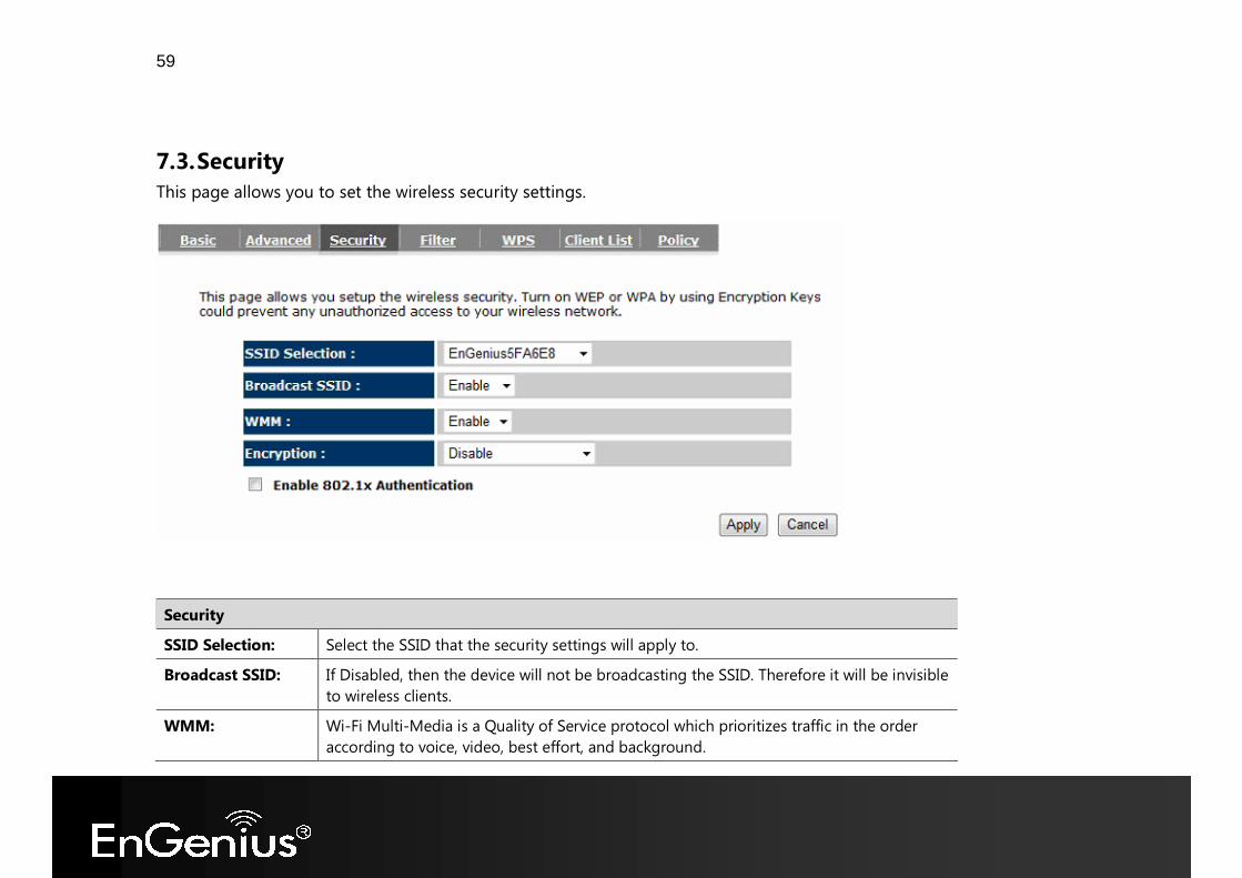
7.3. Security This page allows you to set the wireless security settings.
Security SSID Selection: Select the SSID that the security settings will apply to. Broadcast SSID: If Disabled, then the device will not be broadcasting the SSID. Therefore it will be invisible
to wireless clients. WMM: Wi-Fi Multi-Media is a Quality of Service protocol which prioritizes traffic in the order
according to voice, video, best effort, and background.
60
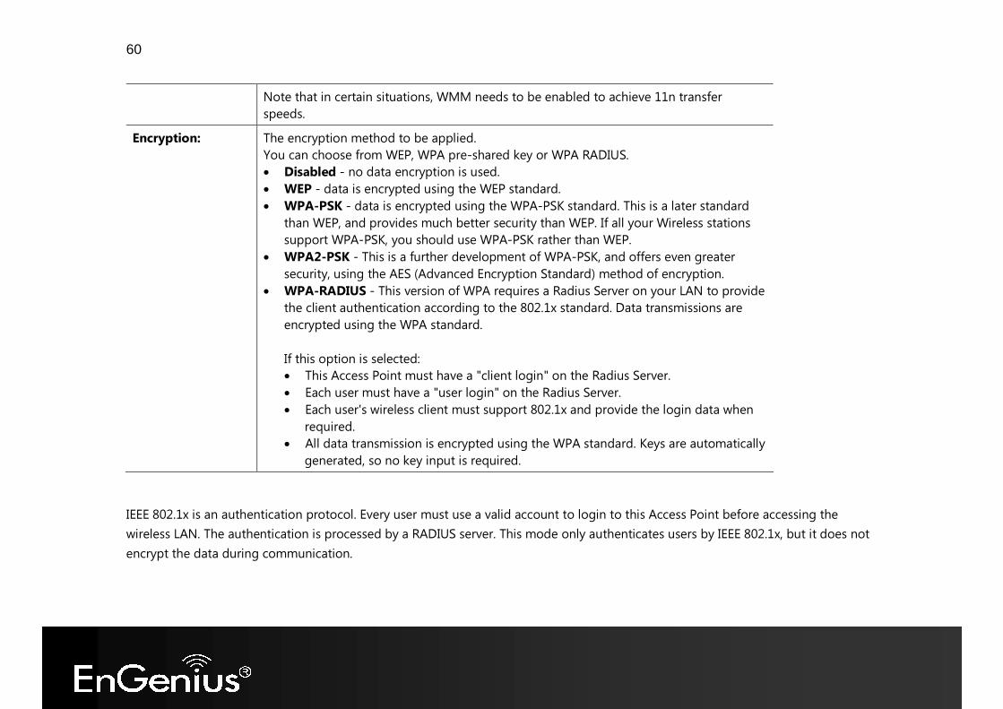
Note that in certain situations, WMM needs to be enabled to achieve 11n transfer speeds.
Encryption: The encryption method to be applied. You can choose from WEP, WPA pre-shared key or WPA RADIUS. • Disabled - no data encryption is used. • WEP - data is encrypted using the WEP standard. • WPA-PSK - data is encrypted using the WPA-PSK standard. This is a later standard
than WEP, and provides much better security than WEP. If all your Wireless stations support WPA-PSK, you should use WPA-PSK rather than WEP.
• WPA2-PSK - This is a further development of WPA-PSK, and offers even greater security, using the AES (Advanced Encryption Standard) method of encryption.
• WPA-RADIUS - This version of WPA requires a Radius Server on your LAN to provide the client authentication according to the 802.1x standard. Data transmissions are encrypted using the WPA standard. If this option is selected: • This Access Point must have a "client login" on the Radius Server. • Each user must have a "user login" on the Radius Server. • Each user's wireless client must support 802.1x and provide the login data when
required. • All data transmission is encrypted using the WPA standard. Keys are automatically
generated, so no key input is required. IEEE 802.1x is an authentication protocol. Every user must use a valid account to login to this Access Point before accessing the wireless LAN. The authentication is processed by a RADIUS server. This mode only authenticates users by IEEE 802.1x, but it does not encrypt the data during communication.
61
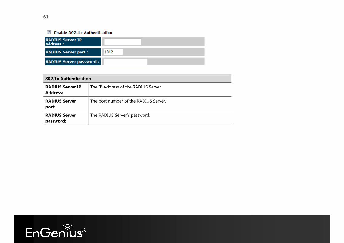
802.1x Authentication RADIUS Server IP Address:
The IP Address of the RADIUS Server
RADIUS Server port:
The port number of the RADIUS Server.
RADIUS Server password:
The RADIUS Server’s password.
62
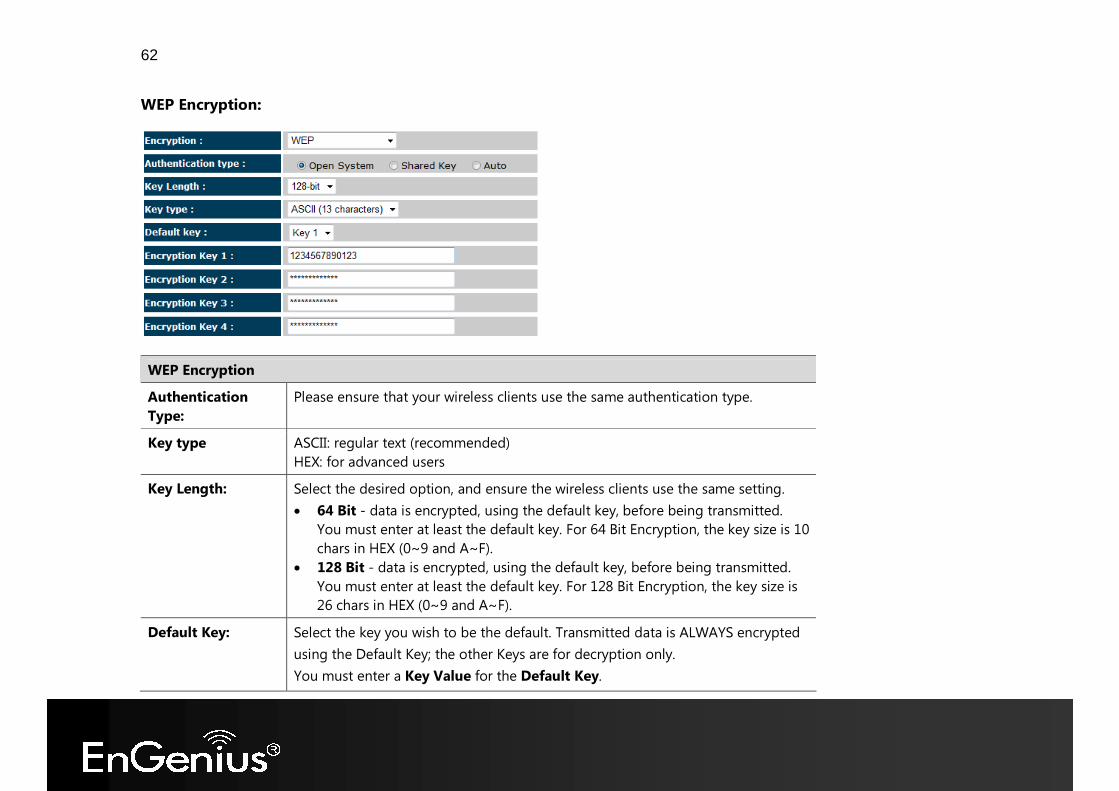
WEP Encryption:
WEP Encryption Authentication Type:
Please ensure that your wireless clients use the same authentication type.
Key type ASCII: regular text (recommended) HEX: for advanced users
Key Length: Select the desired option, and ensure the wireless clients use the same setting. • 64 Bit - data is encrypted, using the default key, before being transmitted.
You must enter at least the default key. For 64 Bit Encryption, the key size is 10 chars in HEX (0~9 and A~F).
• 128 Bit - data is encrypted, using the default key, before being transmitted. You must enter at least the default key. For 128 Bit Encryption, the key size is 26 chars in HEX (0~9 and A~F).
Default Key: Select the key you wish to be the default. Transmitted data is ALWAYS encrypted using the Default Key; the other Keys are for decryption only. You must enter a Key Value for the Default Key.
63
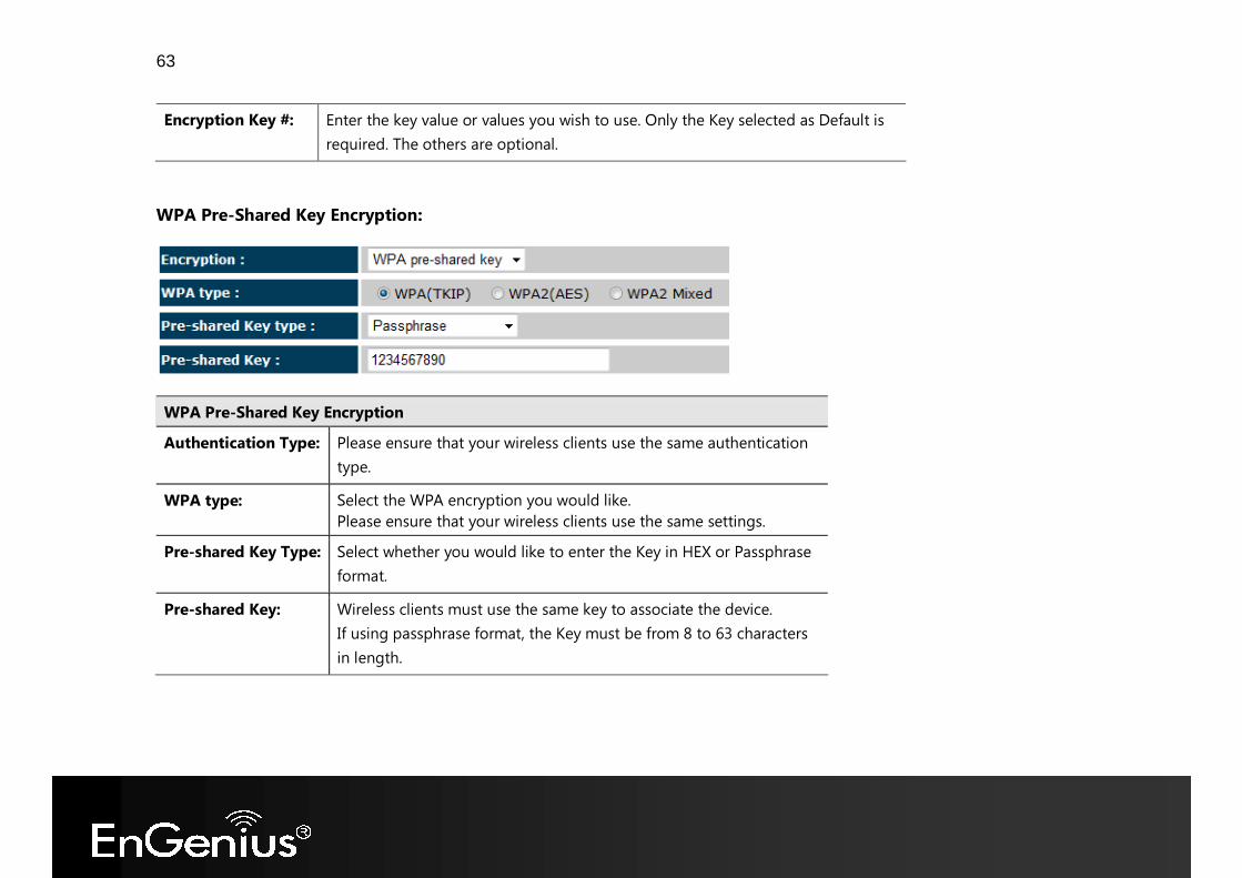
Encryption Key #: Enter the key value or values you wish to use. Only the Key selected as Default is required. The others are optional.
WPA Pre-Shared Key Encryption:
WPA Pre-Shared Key Encryption Authentication Type: Please ensure that your wireless clients use the same authentication
type. WPA type: Select the WPA encryption you would like.
Please ensure that your wireless clients use the same settings. Pre-shared Key Type: Select whether you would like to enter the Key in HEX or Passphrase
format. Pre-shared Key: Wireless clients must use the same key to associate the device.
If using passphrase format, the Key must be from 8 to 63 characters in length.
64
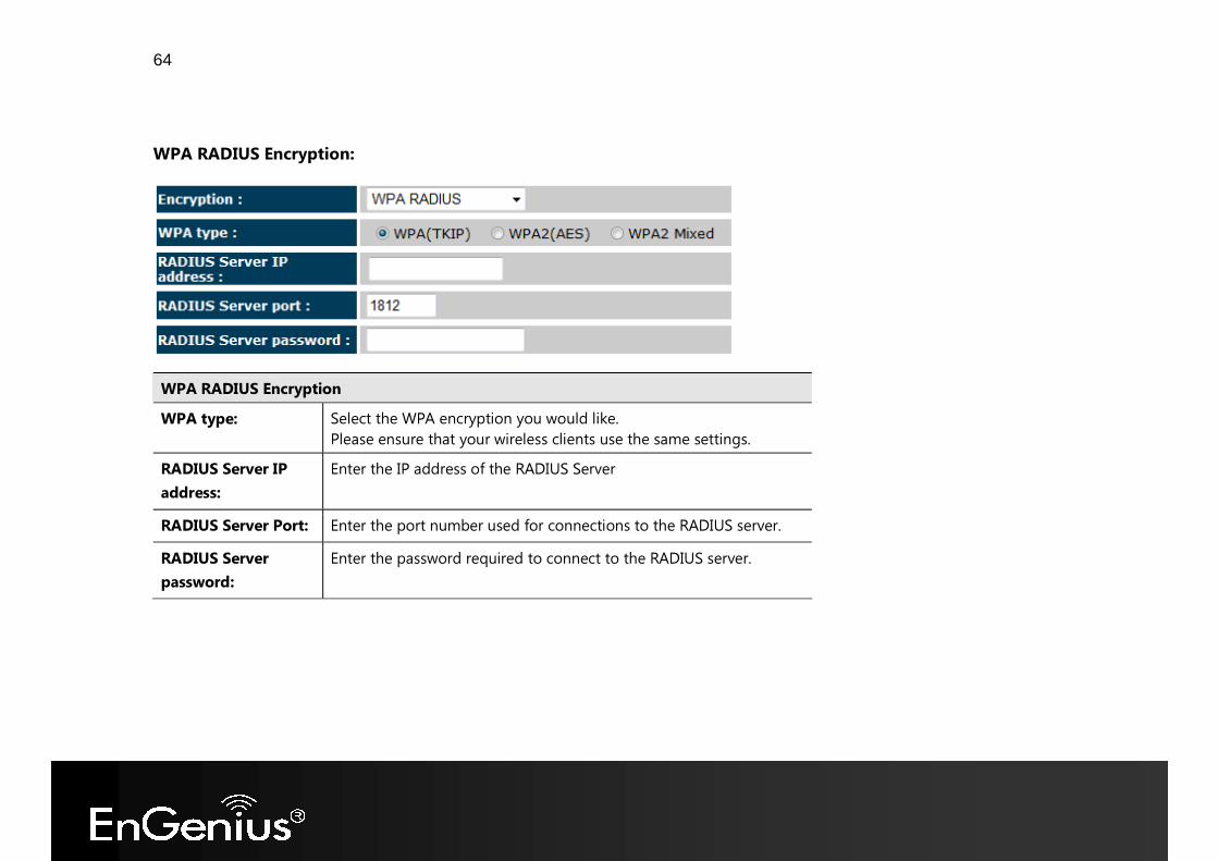
WPA RADIUS Encryption:
WPA RADIUS Encryption WPA type: Select the WPA encryption you would like.
Please ensure that your wireless clients use the same settings. RADIUS Server IP address:
Enter the IP address of the RADIUS Server
RADIUS Server Port: Enter the port number used for connections to the RADIUS server. RADIUS Server password:
Enter the password required to connect to the RADIUS server.
65
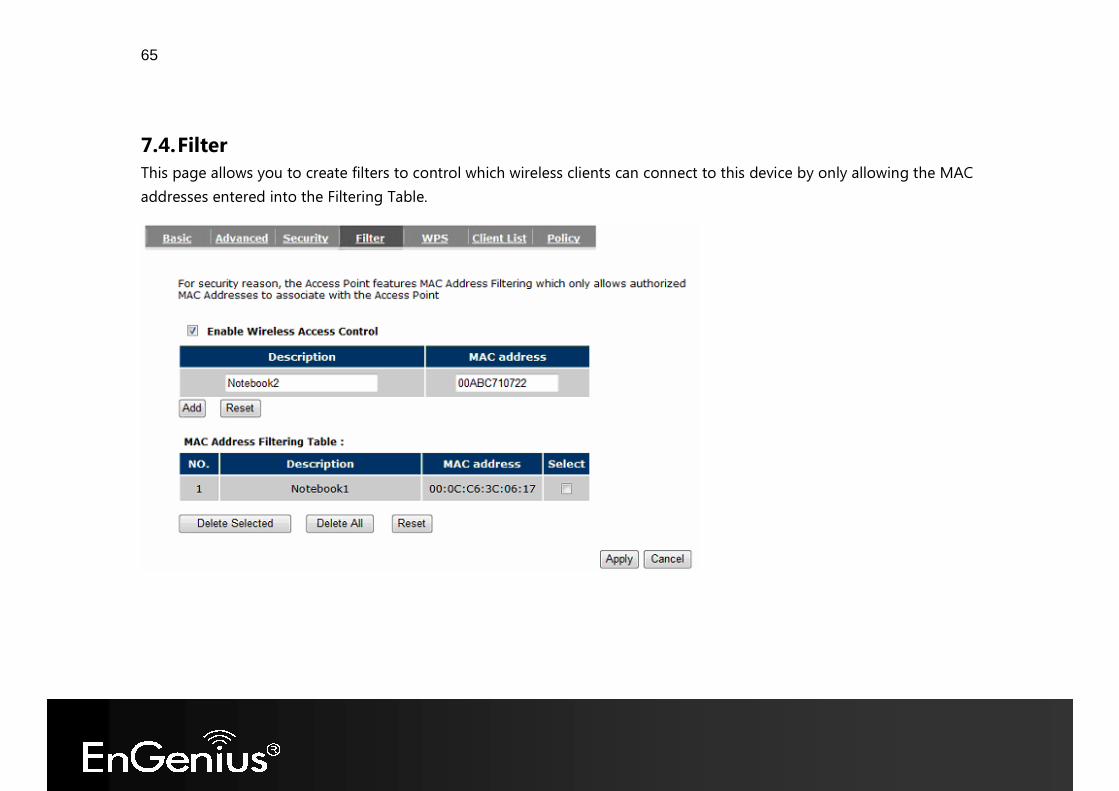
7.4. Filter This page allows you to create filters to control which wireless clients can connect to this device by only allowing the MAC addresses entered into the Filtering Table.
66
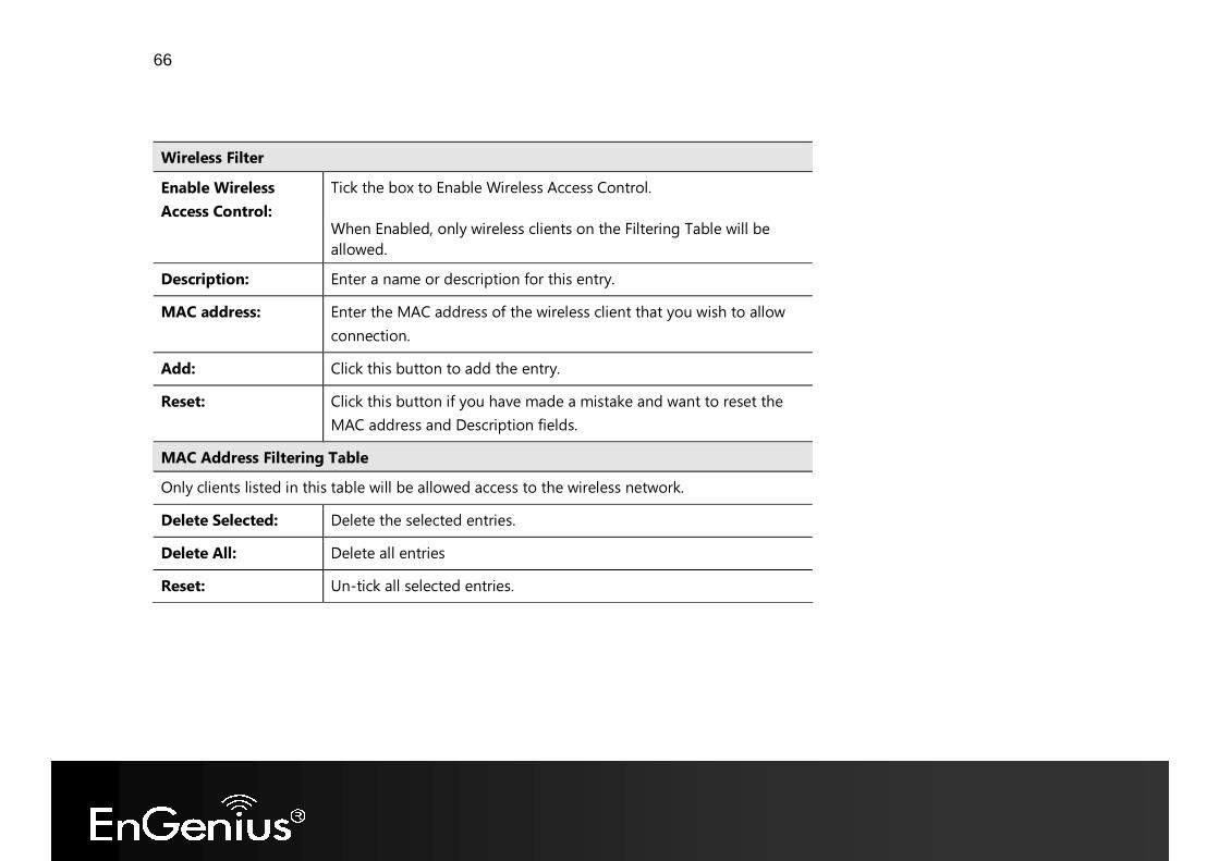
Wireless Filter Enable Wireless Access Control:
Tick the box to Enable Wireless Access Control. When Enabled, only wireless clients on the Filtering Table will be allowed.
Description: Enter a name or description for this entry. MAC address: Enter the MAC address of the wireless client that you wish to allow
connection. Add: Click this button to add the entry. Reset: Click this button if you have made a mistake and want to reset the
MAC address and Description fields. MAC Address Filtering Table Only clients listed in this table will be allowed access to the wireless network. Delete Selected: Delete the selected entries. Delete All: Delete all entries Reset: Un-tick all selected entries.
67
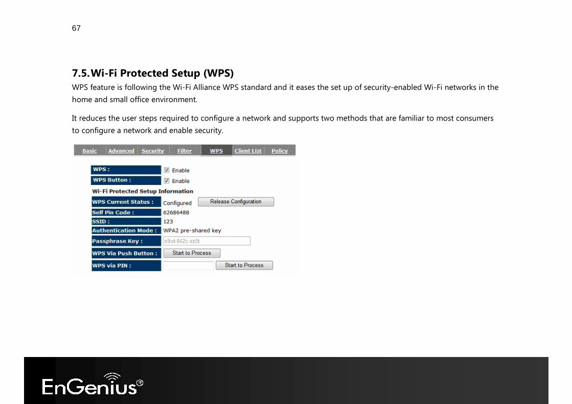
7.5. Wi-Fi Protected Setup (WPS) WPS feature is following the Wi-Fi Alliance WPS standard and it eases the set up of security-enabled Wi-Fi networks in the home and small office environment. It reduces the user steps required to configure a network and supports two methods that are familiar to most consumers to configure a network and enable security.
68
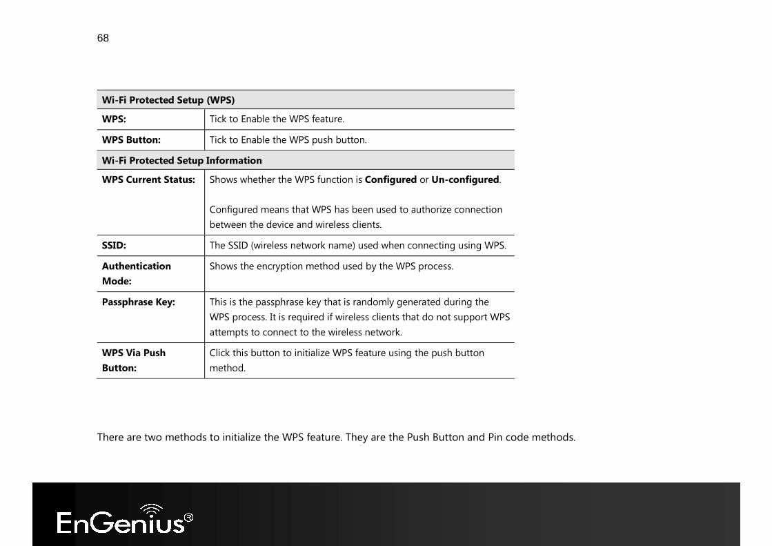
Wi-Fi Protected Setup (WPS) WPS: Tick to Enable the WPS feature. WPS Button: Tick to Enable the WPS push button. Wi-Fi Protected Setup Information WPS Current Status: Shows whether the WPS function is Configured or Un-configured.
Configured means that WPS has been used to authorize connection between the device and wireless clients.
SSID: The SSID (wireless network name) used when connecting using WPS. Authentication Mode:
Shows the encryption method used by the WPS process.
Passphrase Key: This is the passphrase key that is randomly generated during the WPS process. It is required if wireless clients that do not support WPS attempts to connect to the wireless network.
WPS Via Push Button:
Click this button to initialize WPS feature using the push button method.
There are two methods to initialize the WPS feature. They are the Push Button and Pin code methods.
69
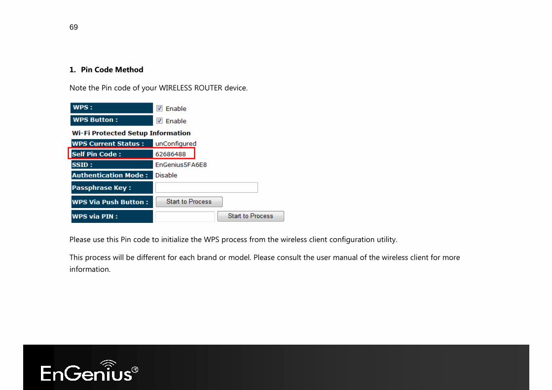
1. Pin Code Method Note the Pin code of your WIRELESS ROUTER device.
Please use this Pin code to initialize the WPS process from the wireless client configuration utility. This process will be different for each brand or model. Please consult the user manual of the wireless client for more information.
70
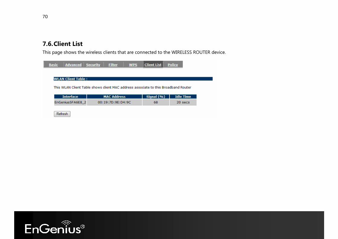
7.6. Client List This page shows the wireless clients that are connected to the WIRELESS ROUTER device.
71
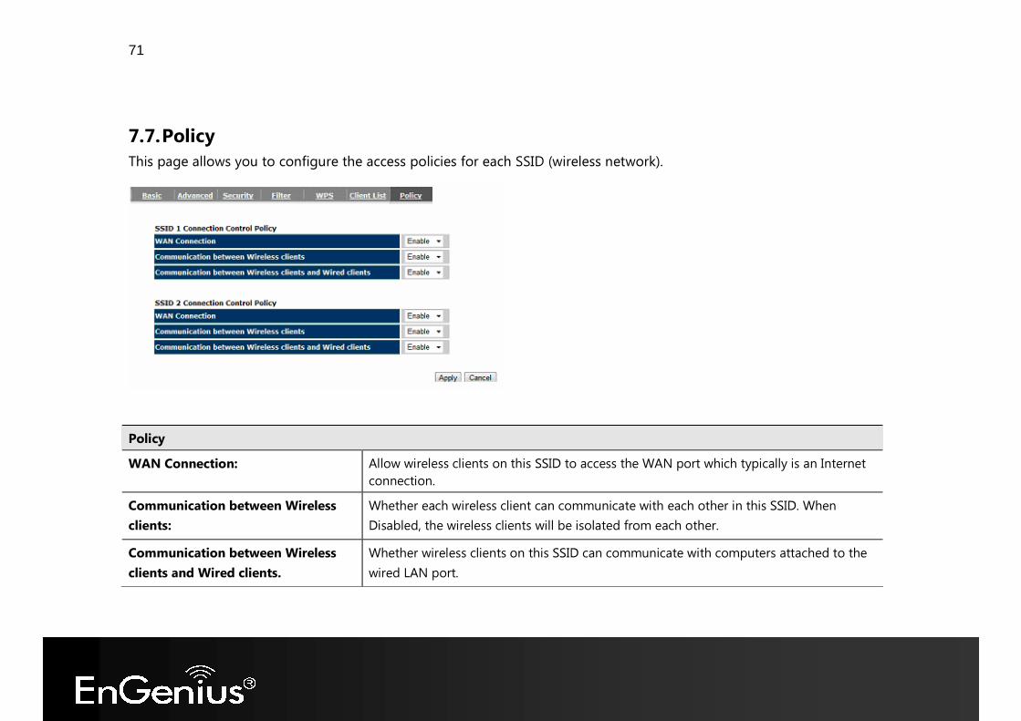
7.7. Policy This page allows you to configure the access policies for each SSID (wireless network).
Policy WAN Connection: Allow wireless clients on this SSID to access the WAN port which typically is an Internet
connection. Communication between Wireless clients:
Whether each wireless client can communicate with each other in this SSID. When Disabled, the wireless clients will be isolated from each other.
Communication between Wireless clients and Wired clients.
Whether wireless clients on this SSID can communicate with computers attached to the wired LAN port.
72
8. Firewall The Internet section allows you to set the access control and Firewall settings.
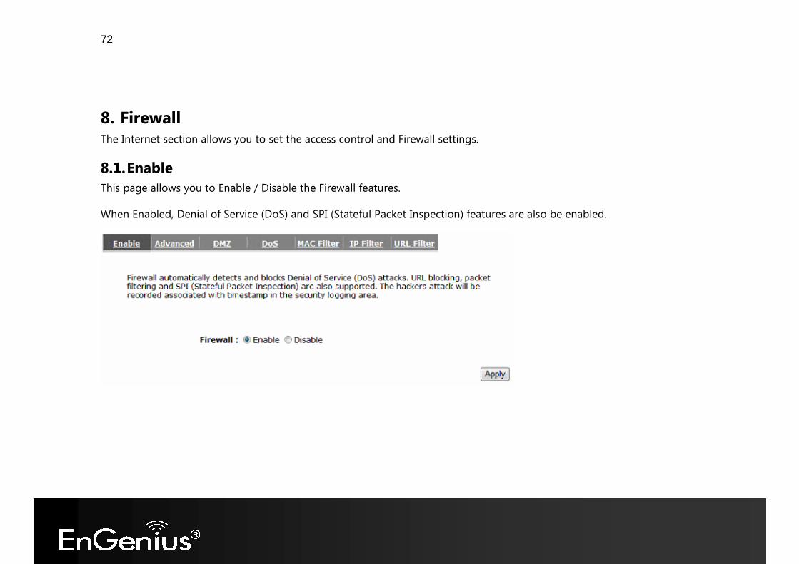
8.1. Enable This page allows you to Enable / Disable the Firewall features. When Enabled, Denial of Service (DoS) and SPI (Stateful Packet Inspection) features are also be enabled.
73
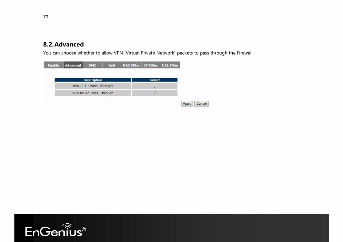
8.2. Advanced You can choose whether to allow VPN (Virtual Private Network) packets to pass through the Firewall.
74
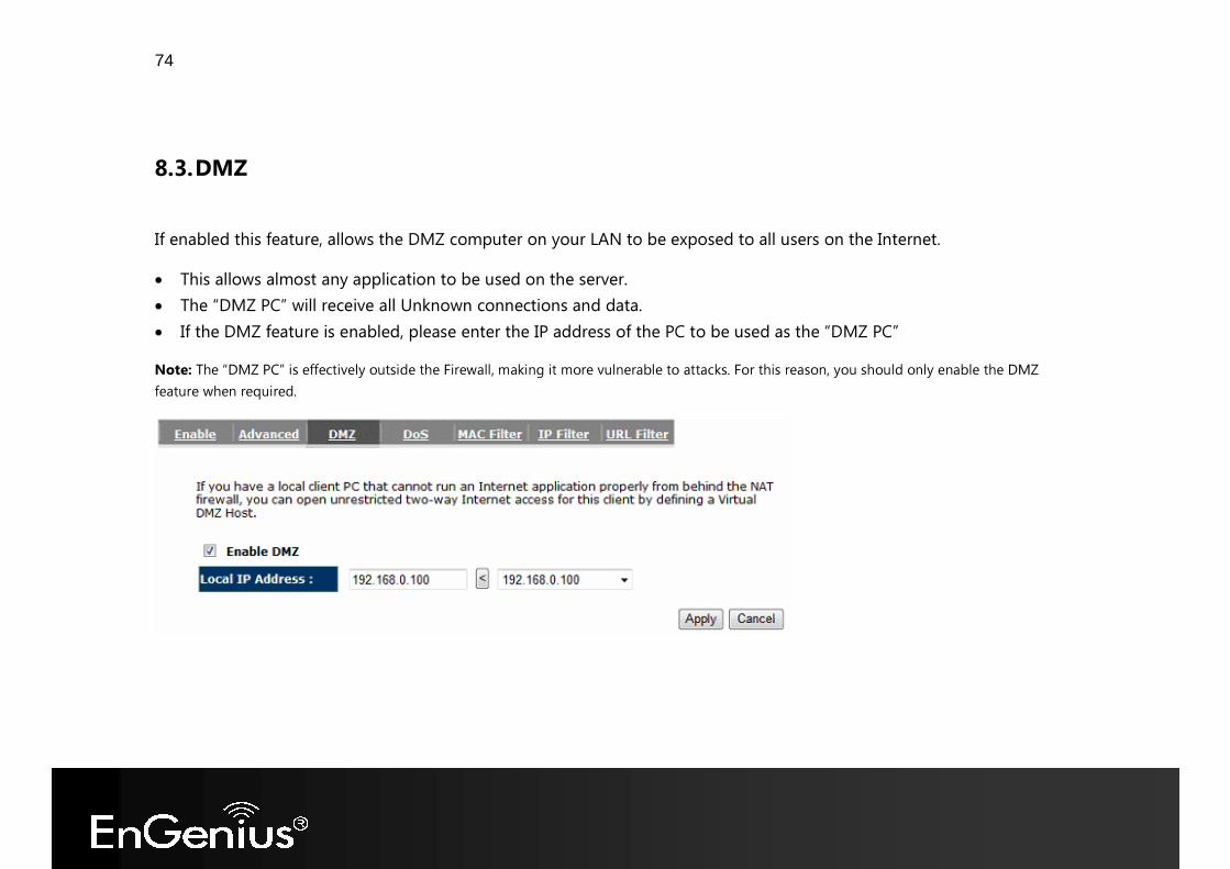
8.3. DMZ If enabled this feature, allows the DMZ computer on your LAN to be exposed to all users on the Internet. • This allows almost any application to be used on the server. • The “DMZ PC” will receive all Unknown connections and data. • If the DMZ feature is enabled, please enter the IP address of the PC to be used as the “DMZ PC” Note: The “DMZ PC” is effectively outside the Firewall, making it more vulnerable to attacks. For this reason, you should only enable the DMZ feature when required.
75
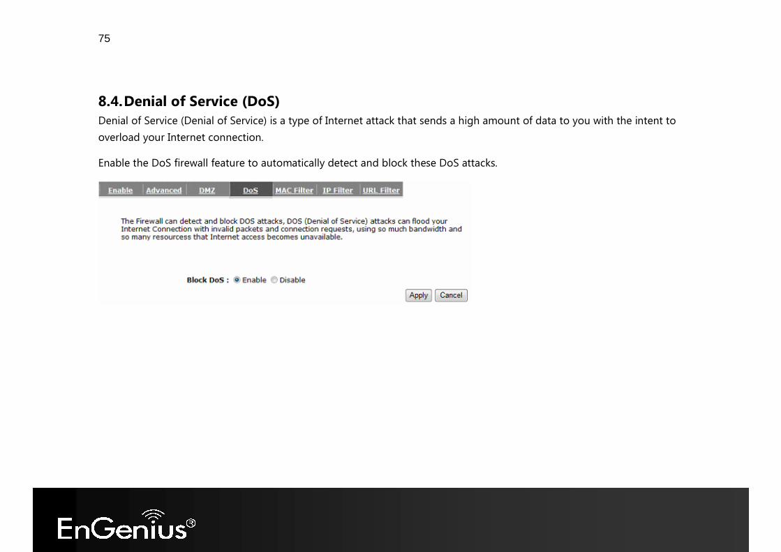
8.4. Denial of Service (DoS) Denial of Service (Denial of Service) is a type of Internet attack that sends a high amount of data to you with the intent to overload your Internet connection. Enable the DoS firewall feature to automatically detect and block these DoS attacks.
76
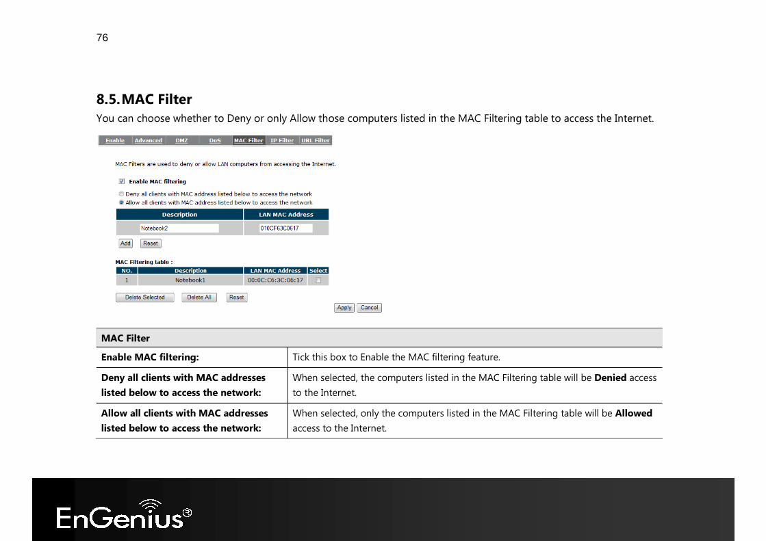
8.5. MAC Filter You can choose whether to Deny or only Allow those computers listed in the MAC Filtering table to access the Internet.
MAC Filter Enable MAC filtering: Tick this box to Enable the MAC filtering feature. Deny all clients with MAC addresses listed below to access the network:
When selected, the computers listed in the MAC Filtering table will be Denied access to the Internet.
Allow all clients with MAC addresses listed below to access the network:
When selected, only the computers listed in the MAC Filtering table will be Allowed access to the Internet.
77
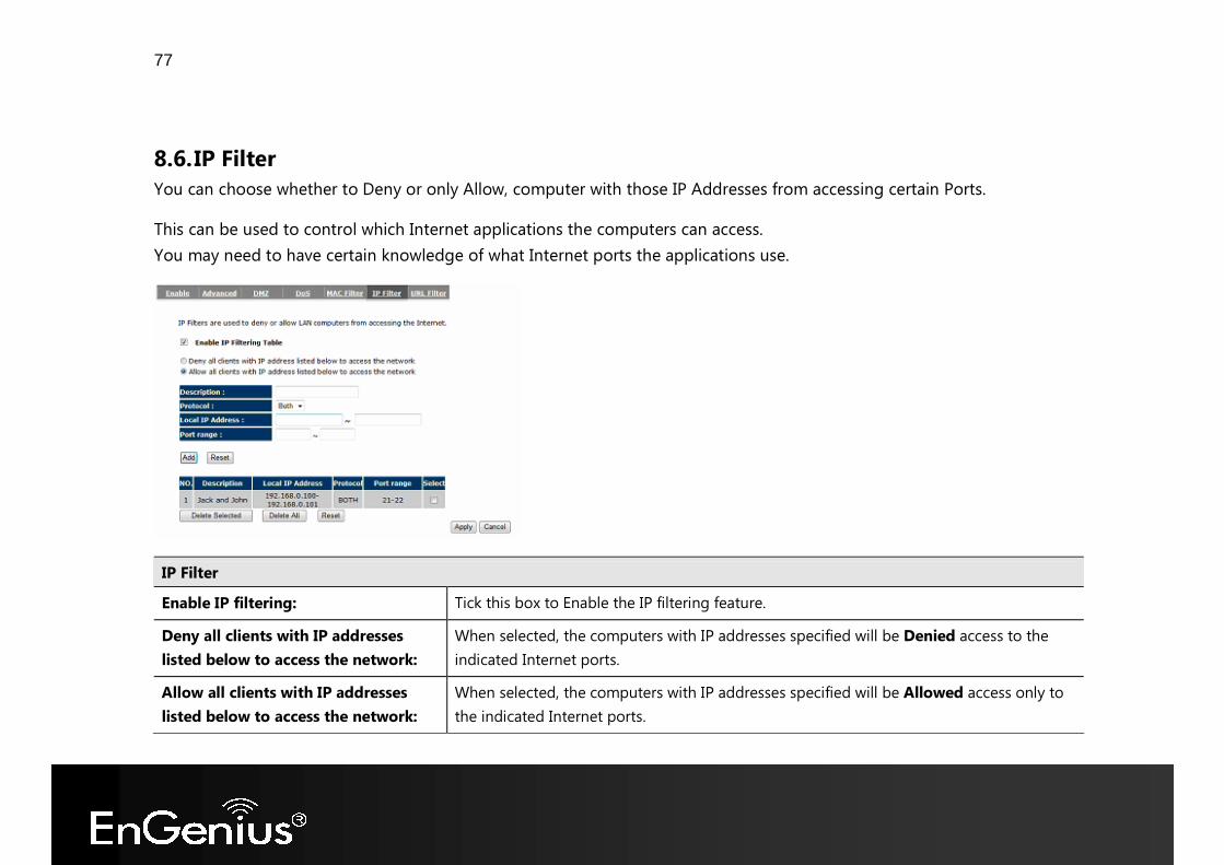
8.6. IP Filter You can choose whether to Deny or only Allow, computer with those IP Addresses from accessing certain Ports. This can be used to control which Internet applications the computers can access. You may need to have certain knowledge of what Internet ports the applications use.
IP Filter Enable IP filtering: Tick this box to Enable the IP filtering feature. Deny all clients with IP addresses listed below to access the network:
When selected, the computers with IP addresses specified will be Denied access to the indicated Internet ports.
Allow all clients with IP addresses listed below to access the network:
When selected, the computers with IP addresses specified will be Allowed access only to the indicated Internet ports.
78
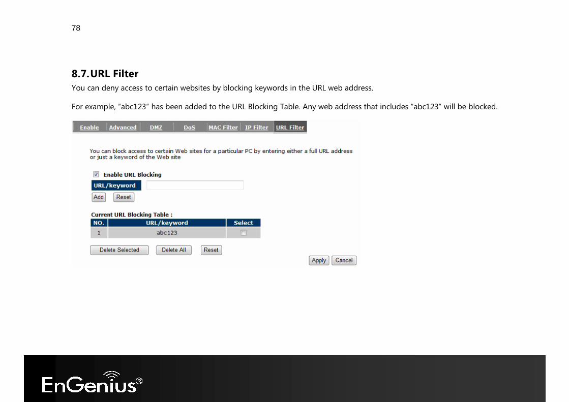
8.7. URL Filter You can deny access to certain websites by blocking keywords in the URL web address. For example, “abc123” has been added to the URL Blocking Table. Any web address that includes “abc123” will be blocked.

79
9. Advanced The Internet section allows you to configure the Advanced settings of the router.
9.1. Network Address Translation (NAT) This page allows you to Enable / Disable the Network Address Translation (NAT) feature. The NAT is required to share one Internet account with multiple LAN users. It also is required for certain Firewall features to work properly.
80
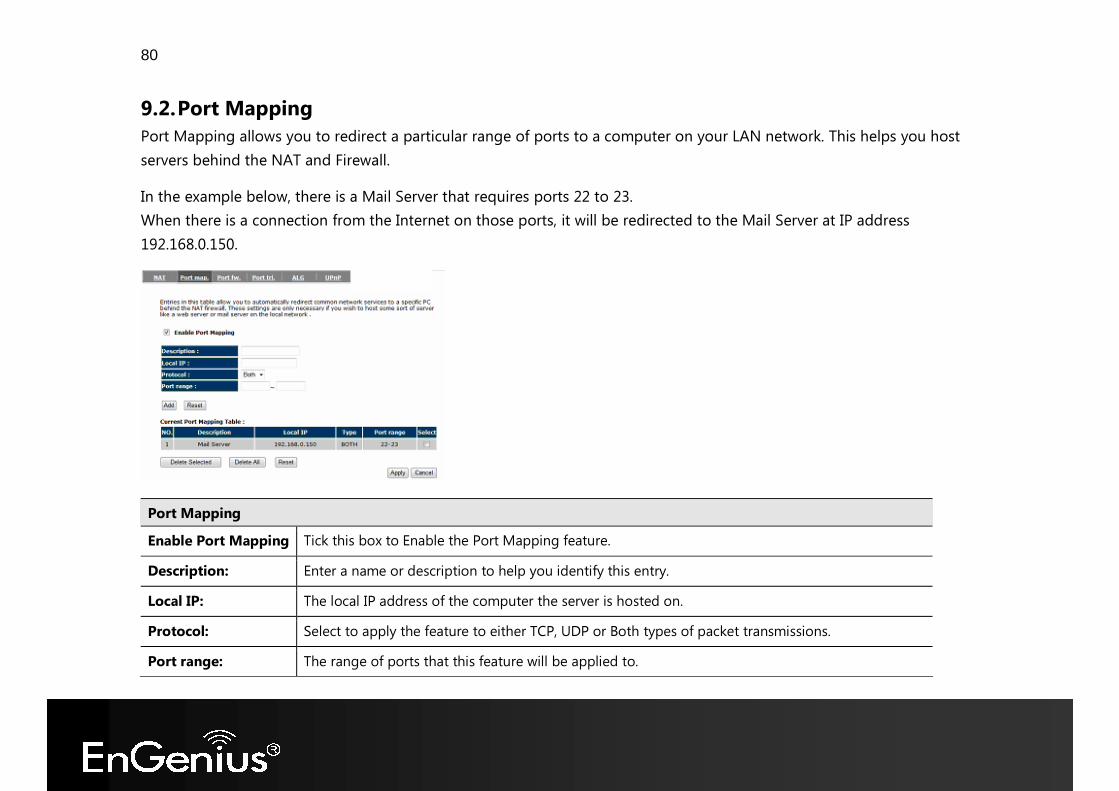
9.2. Port Mapping Port Mapping allows you to redirect a particular range of ports to a computer on your LAN network. This helps you host servers behind the NAT and Firewall. In the example below, there is a Mail Server that requires ports 22 to 23. When there is a connection from the Internet on those ports, it will be redirected to the Mail Server at IP address 192.168.0.150.
Port Mapping Enable Port Mapping Tick this box to Enable the Port Mapping feature. Description: Enter a name or description to help you identify this entry. Local IP: The local IP address of the computer the server is hosted on. Protocol: Select to apply the feature to either TCP, UDP or Both types of packet transmissions. Port range: The range of ports that this feature will be applied to.
81
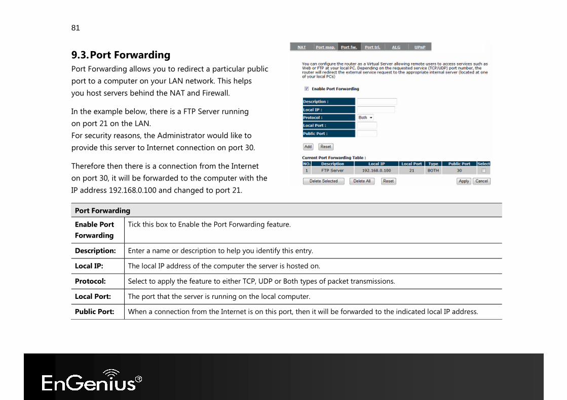
9.3. Port Forwarding Port Forwarding allows you to redirect a particular public port to a computer on your LAN network. This helps you host servers behind the NAT and Firewall. In the example below, there is a FTP Server running on port 21 on the LAN. For security reasons, the Administrator would like to provide this server to Internet connection on port 30. Therefore then there is a connection from the Internet on port 30, it will be forwarded to the computer with the IP address 192.168.0.100 and changed to port 21.
Port Forwarding Enable Port Forwarding
Tick this box to Enable the Port Forwarding feature.
Description: Enter a name or description to help you identify this entry. Local IP: The local IP address of the computer the server is hosted on. Protocol: Select to apply the feature to either TCP, UDP or Both types of packet transmissions. Local Port: The port that the server is running on the local computer. Public Port: When a connection from the Internet is on this port, then it will be forwarded to the indicated local IP address.
82
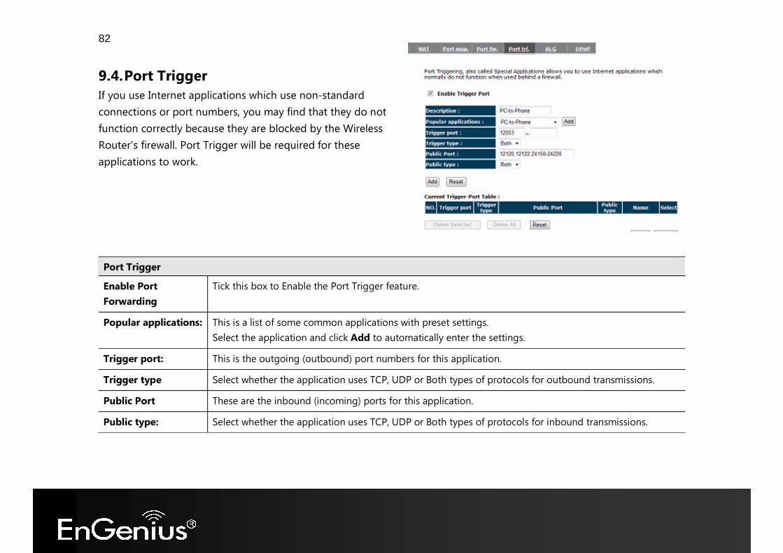
9.4. Port Trigger If you use Internet applications which use non-standard connections or port numbers, you may find that they do not function correctly because they are blocked by the Wireless Router's firewall. Port Trigger will be required for these applications to work.
Port Trigger Enable Port Forwarding
Tick this box to Enable the Port Trigger feature.
Popular applications: This is a list of some common applications with preset settings. Select the application and click Add to automatically enter the settings.
Trigger port: This is the outgoing (outbound) port numbers for this application. Trigger type Select whether the application uses TCP, UDP or Both types of protocols for outbound transmissions. Public Port These are the inbound (incoming) ports for this application. Public type: Select whether the application uses TCP, UDP or Both types of protocols for inbound transmissions.
83
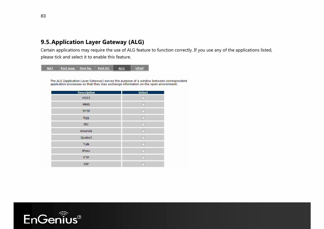
9.5. Application Layer Gateway (ALG) Certain applications may require the use of ALG feature to function correctly. If you use any of the applications listed, please tick and select it to enable this feature.
84
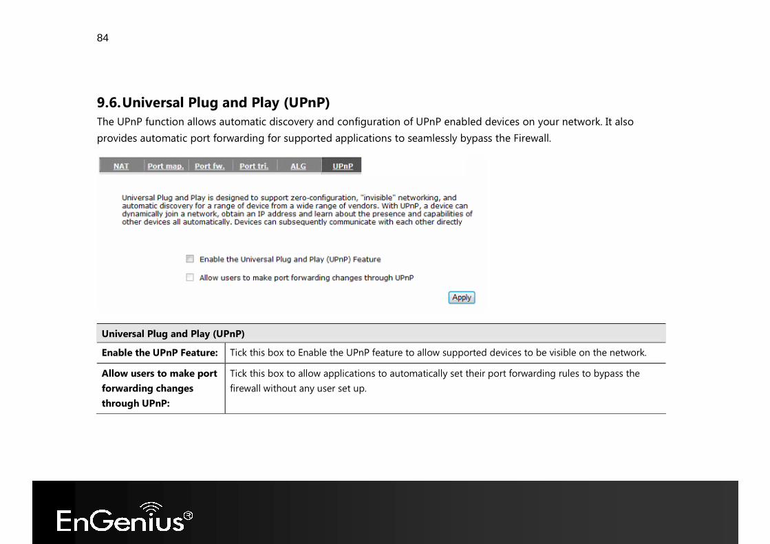
9.6. Universal Plug and Play (UPnP) The UPnP function allows automatic discovery and configuration of UPnP enabled devices on your network. It also provides automatic port forwarding for supported applications to seamlessly bypass the Firewall.
Universal Plug and Play (UPnP) Enable the UPnP Feature: Tick this box to Enable the UPnP feature to allow supported devices to be visible on the network. Allow users to make port forwarding changes through UPnP:
Tick this box to allow applications to automatically set their port forwarding rules to bypass the firewall without any user set up.
85
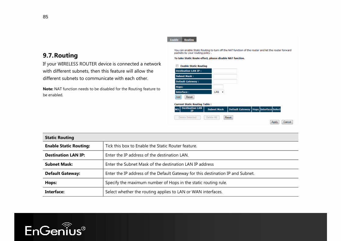
9.7. Routing If your WIRELESS ROUTER device is connected a network with different subnets, then this feature will allow the different subnets to communicate with each other. Note: NAT function needs to be disabled for the Routing feature to be enabled.
Static Routing Enable Static Routing: Tick this box to Enable the Static Router feature. Destination LAN IP: Enter the IP address of the destination LAN. Subnet Mask: Enter the Subnet Mask of the destination LAN IP address Default Gateway: Enter the IP address of the Default Gateway for this destination IP and Subnet. Hops: Specify the maximum number of Hops in the static routing rule. Interface: Select whether the routing applies to LAN or WAN interfaces.
86
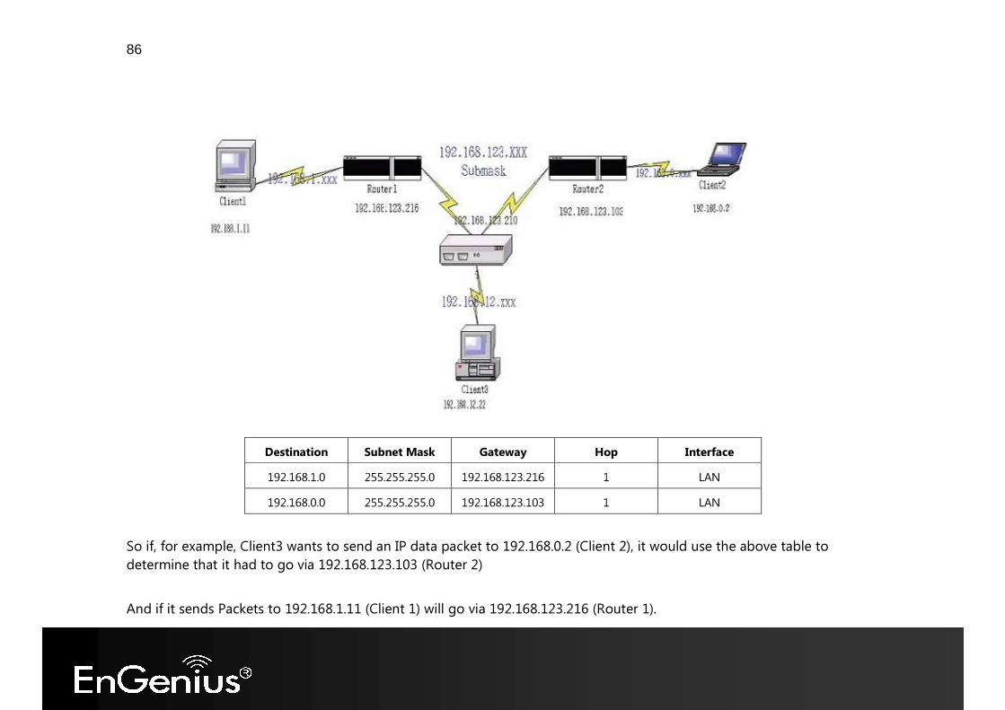
Destination Subnet Mask Gateway Hop Interface 192.168.1.0 255.255.255.0 192.168.123.216 1 LAN 192.168.0.0 255.255.255.0 192.168.123.103 1 LAN
So if, for example, Client3 wants to send an IP data packet to 192.168.0.2 (Client 2), it would use the above table to determine that it had to go via 192.168.123.103 (Router 2) And if it sends Packets to 192.168.1.11 (Client 1) will go via 192.168.123.216 (Router 1).
87
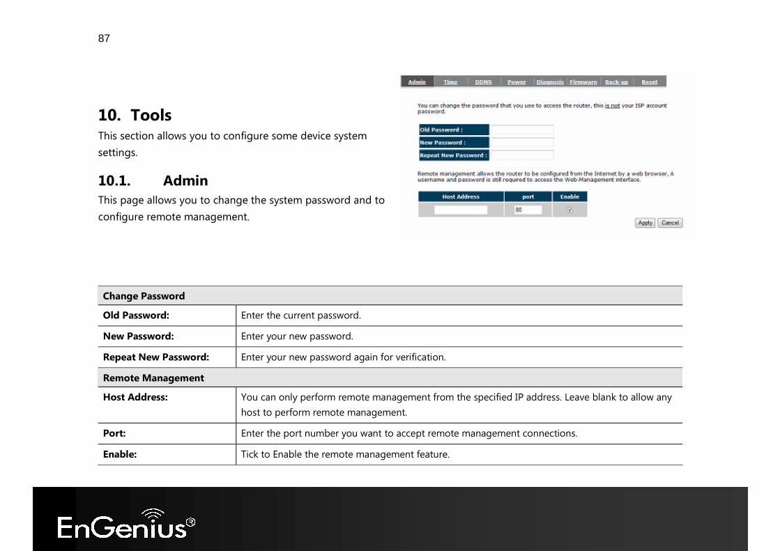
10. Tools This section allows you to configure some device system settings.
10.1. Admin This page allows you to change the system password and to configure remote management. Change Password Old Password: Enter the current password. New Password: Enter your new password. Repeat New Password: Enter your new password again for verification. Remote Management Host Address: You can only perform remote management from the specified IP address. Leave blank to allow any
host to perform remote management. Port: Enter the port number you want to accept remote management connections. Enable: Tick to Enable the remote management feature.
88
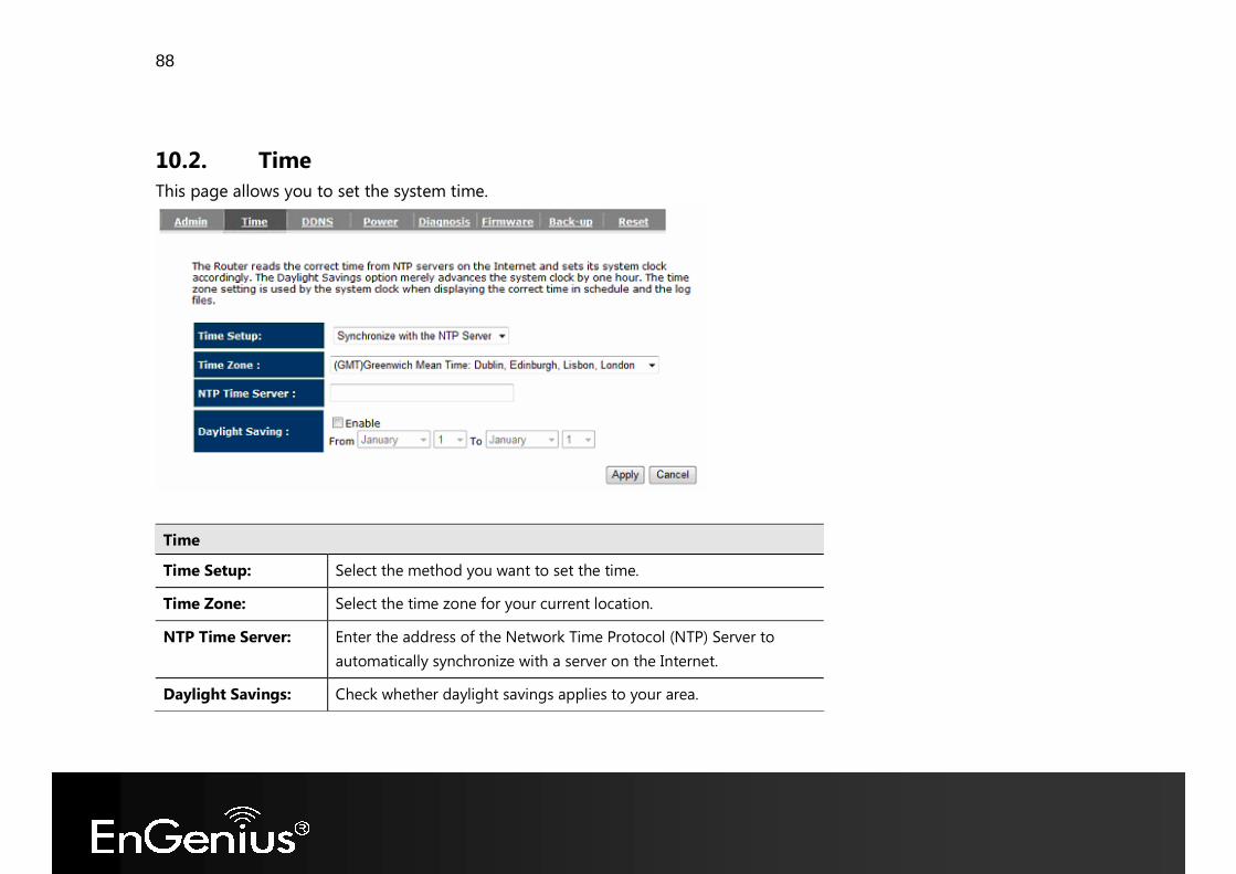
10.2. Time This page allows you to set the system time.
Time Time Setup: Select the method you want to set the time. Time Zone: Select the time zone for your current location. NTP Time Server: Enter the address of the Network Time Protocol (NTP) Server to
automatically synchronize with a server on the Internet. Daylight Savings: Check whether daylight savings applies to your area.
89
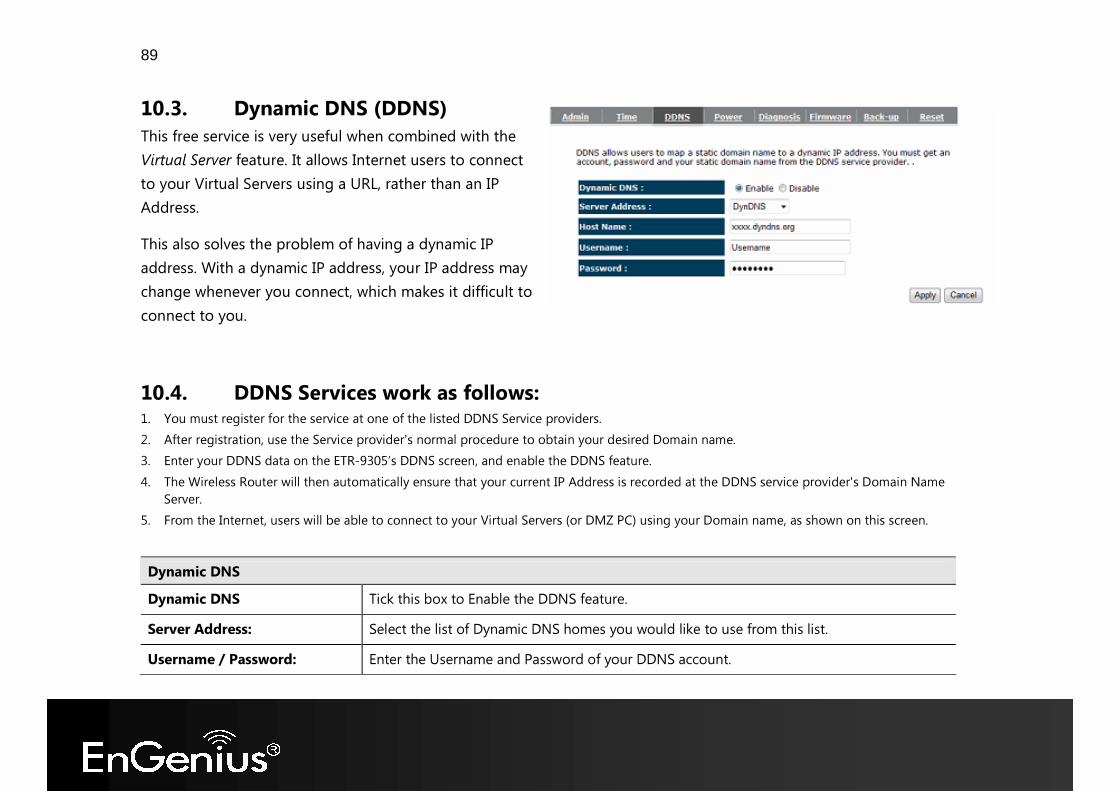
10.3. Dynamic DNS (DDNS) This free service is very useful when combined with the Virtual Server feature. It allows Internet users to connect to your Virtual Servers using a URL, rather than an IP Address. This also solves the problem of having a dynamic IP address. With a dynamic IP address, your IP address may change whenever you connect, which makes it difficult to connect to you.
10.4. DDNS Services work as follows: 1. You must register for the service at one of the listed DDNS Service providers. 2. After registration, use the Service provider's normal procedure to obtain your desired Domain name. 3. Enter your DDNS data on the ETR-9305’s DDNS screen, and enable the DDNS feature. 4. The Wireless Router will then automatically ensure that your current IP Address is recorded at the DDNS service provider's Domain Name
Server. 5. From the Internet, users will be able to connect to your Virtual Servers (or DMZ PC) using your Domain name, as shown on this screen. Dynamic DNS Dynamic DNS Tick this box to Enable the DDNS feature. Server Address: Select the list of Dynamic DNS homes you would like to use from this list. Username / Password: Enter the Username and Password of your DDNS account.
90
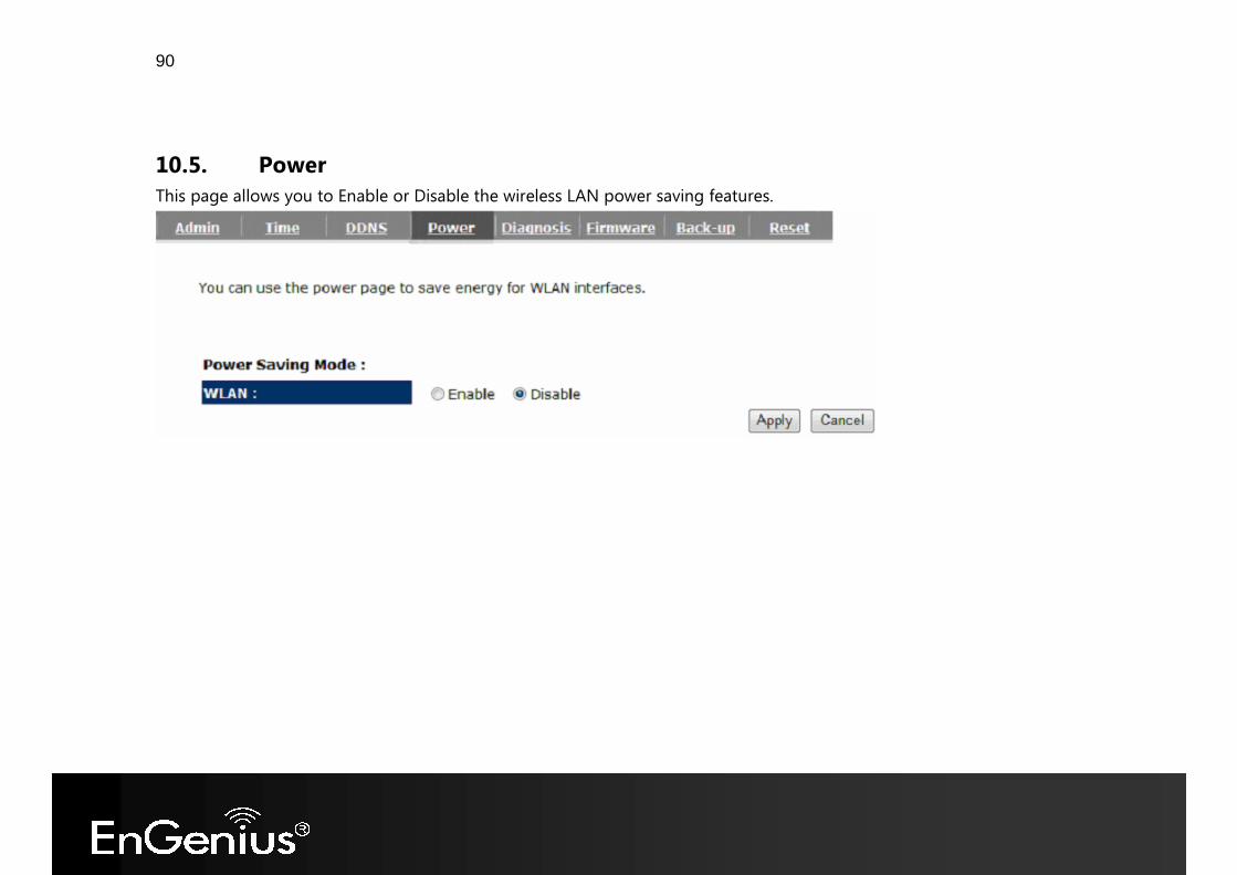
10.5. Power This page allows you to Enable or Disable the wireless LAN power saving features.
91
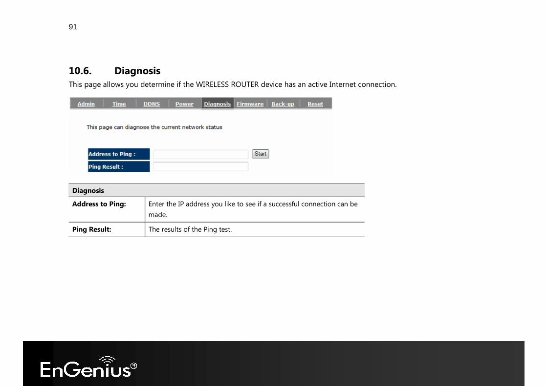
10.6. Diagnosis This page allows you determine if the WIRELESS ROUTER device has an active Internet connection.
Diagnosis Address to Ping: Enter the IP address you like to see if a successful connection can be
made. Ping Result: The results of the Ping test.
92
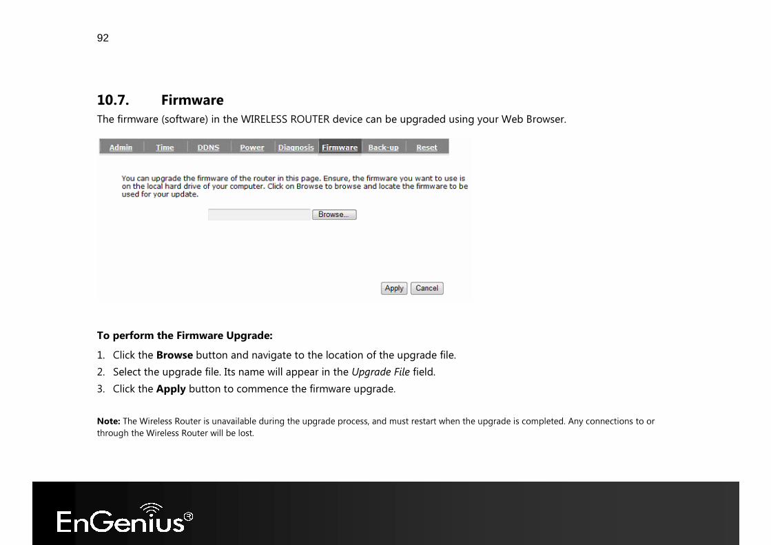
10.7. Firmware The firmware (software) in the WIRELESS ROUTER device can be upgraded using your Web Browser.
To perform the Firmware Upgrade: 1. Click the Browse button and navigate to the location of the upgrade file. 2. Select the upgrade file. Its name will appear in the Upgrade File field. 3. Click the Apply button to commence the firmware upgrade. Note: The Wireless Router is unavailable during the upgrade process, and must restart when the upgrade is completed. Any connections to or through the Wireless Router will be lost.

93
10.8. Back-up
Back-up Restore to factory default:
Restores the device to factory default settings.
Backup Settings: Save the current configuration settings to a file. Restore Settings: Restores a previously saved configuration file.
Click Browse to select the file. Then Upload to load the settings.
94
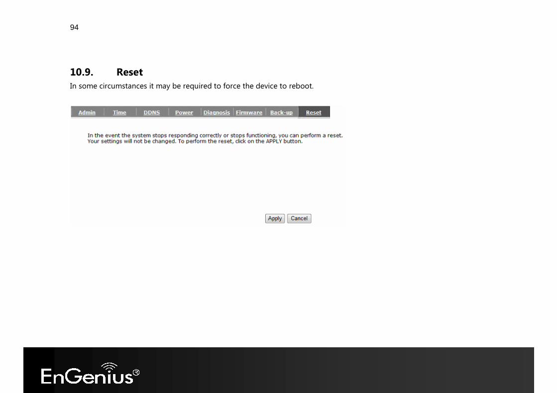
10.9. Reset In some circumstances it may be required to force the device to reboot.
95
Appendix A – FCC Interference Statement Federal Communication Commission Interference Statement This equipment has been tested and found to comply with the limits for a Class B digital device, pursuant to Part 15 of the FCC Rules. These limits are designed to provide reasonable protection against harmful interference in a residential installation. This equipment generates, uses and can radiate radio frequency energy and, if not installed and used in accordance with the instructions, may cause harmful interference to radio communications. However, there is no guarantee that interference will not occur in a particular installation. If this equipment does cause harmful interference to radio or television reception, which can be determined by turning the equipment off and on, the user is encouraged to try to correct the interference by one of the following measures:
� Reorient or relocate the receiving antenna. � Increase the separation between the equipment and receiver. � Connect the equipment into an outlet on a circuit different from that to which the receiver is connected. � Consult the dealer or an experienced radio/TV technician for help.
This device complies with Part 15 of the FCC Rules. Operation is subject to the following two conditions: (1) This device may not cause harmful interference, and (2) this device must accept any interference received, including interference that may cause undesired operation.

96
FCC Caution: Any changes or modifications not expressly approved by the party responsible for compliance could void the user's authority to operate this equipment.
IMPORTANT NOTE:
FCC Radiation Exposure Statement:
This equipment complies with FCC radiation exposure limits set forth for an uncontrolled environment. This equipment should be installed and operated with minimum distance 20cm between the radiator & your body.
We declare that the product is limited in CH1~CH11 by specified firmware controlled in the USA.
This transmitter must not be co-located or operating in conjunction with any other antenna or transmitter.
97
Appendix B – Industry Canada statement
This device complies with RSS-210 of the Industry Canada Rules. Operation is subject to the following two conditions: (1) This device may not cause harmful interference, and (2) this device must accept any interference received, including interference that may cause undesired operation.
French translation:
Ce dispositif est conforme à la norme CNR-210 d'Industrie Canada applicable aux appareils radio exempts de licence. Son fonctionnement est sujet aux deux conditions suivantes: (1) le dispositif ne doit pas produire de brouillage préjudiciable, et (2) ce dispositif doit accepter tout brouillage reçu, y compris un brouillage susceptible de provoquer un fonctionnement indésirable.
IMPORTANT NOTE: (For mobile device use)
Radiation Exposure Statement:
This equipment complies with IC radiation exposure limits set forth for an uncontrolled environment. This equipment should be installed and operated with minimum distance 20cm between the radiator & your body.
Caution:
The device for the band 5150-5250 MHz is only for indoor usage to reduce potential for harmful interference to co-channel mobile satellite systems.
High power radars are allocated as primary users (meaning they have priority) of 5250-5350 MHz and 5650-5850 MHz and these radars could cause interference and/or damage to LE-LAN devices.
98
The band from 5600-5650MHz will be disabled by the proprietary software during the manufacturing and which cannot be changed by the end-user.
French translation:
NOTE IMPORTANTE: (Pour l'utilisation de dispositifs mobiles) Déclaration d'exposition aux radiations: Cet équipement est conforme aux limites d'exposition aux rayonnements IC établies pour un environnement non contrôlé. Cet équipement doit être installé et utilisé avec un minimum de 20 cm de distance entre la source de rayonnement et votre corps. Avertissement:
Le dispositif fonctionnant dans la bande 5150-5250 MHz est réservé uniquement pour une utilisation à l'intérieur afin de réduire les risques de brouillage préjudiciable aux systèmes de satellites mobiles utilisant les mêmes canaux.
Les utilisateurs de radars de haute puissance sont désignés utilisateurs principaux (c.-à-d., qu'ils ont la priorité) pour les bandes 5250-5350 MHz et 5650-5850 MHz et que ces radars pourraient causer du brouillage et/ou des dommages aux dispositifs LAN-EL.
La bande de frequence de 5600-5650MHz devra etre desactivee par logiciel lors de la conception et ne devra comporter aucune possibilite de modification par l'utilisateur final.
=========================================================
99
(The user manual of transmitter devices equipped with detachable antennas shall contain the following information in a conspicuous location: )
This device has been designed to operate with an antenna having a maximum gain of [x] dB. Antenna having a higher gain is strictly prohibited per regulations of Industry Canada. The required antenna impedance is 50 ohms.
Under Industry Canada regulations, this radio transmitter may only operate using an antenna of a type and maximum (or lesser) gain approved for the transmitter by Industry Canada. To reduce potential radio interference to other users, the antenna type and its gain should be so chosen that the equivalent isotropically radiated power (e.i.r.p.) is not more than that necessary for successful communication.
French translation:
(Le manuel d'utilisation de dispositifs émetteurs équipés d'antennes amovibles doit contenir les informations suivantes
dans un endroit bien en vue:)
Ce dispositif a été conçu pour fonctionner avec une antenne ayant un gain maximal de dB [x]. Une antenne à gain plus élevé est strictement interdite par les règlements d'Industrie Canada. L'impédance d'antenne requise est de 50 ohms.
Conformément à la réglementation d'Industrie Canada, le présent émetteur radio peutfonctionner avec une antenne d'un type et d'un gain maximal (ou inférieur) approuvé pourl'émetteur par Industrie Canada. Dans le but de réduire les risques de brouillage radioélectriqueà l'intention des autres utilisateurs, il faut choisir le type d'antenne et son gain de sorte que
100
lapuissance isotrope rayonnée équivalente (p.i.r.e.) ne dépasse pas l'intensité nécessaire àl'établissement d'une communication satisfaisante.
IMPORTANT NOTE: (For Portable device use)
Radiation Exposure Statement:
The product comply with the US/Canada portable RF exposure limit set forth for an uncontrolled environment and are safe for intended operation as described in this manual. The further RF exposure reduction can be achieved if the product can be kept as far as possible from the user body or set the device to lower output power if such function is available.
French translation:
NOTE IMPORTANTE: (Pour l'utilisation des appareils portables) Déclaration d'exposition aux radiations: Le produit est conforme aux limites d'exposition pour les appareils portables RF pour les Etats-Unis et le Canada établies pour un environnement non contrôlé.
Le produit est sûr pour un fonctionnement tel que décrit dans ce manuel. La réduction aux expositions RF peut être augmentée si l'appareil peut être conservé aussi loin que possible du corps de l'utilisateur ou que le dispositif est réglé sur la puissance de sortie la plus faible si une telle fonction est disponible.
101
This device is intended only for OEM integrators un der the following conditions: (For module device us e)
1) The antenna must be installed such that 20 cm is maintained between the antenna and users, and
2) The transmitter module may not be co-located with any other transmitter or antenna,
3) For all products market in Canada, OEM has to limit the operation channels in CH1 to CH11 for 2.4G band by supplied firmware programming tool. OEM shall not supply any tool or info to the end-user regarding to Regulatory Domain change.
As long as 3 conditions above are met, further transmitter test will not be required. However, the OEM integrator is still responsible for testing their end-product for any additional compliance requirements required with this module installed.
French translation :
Cet appareil est conçu uniquement pour les intégrateurs OEM dans les conditions suivantes: (Pour utilisation de dispositif module)
1) L'antenne doit être installée de telle sorte qu'une distance de 20 cm est respectée entre l'antenne et les utilisateurs, et 2) Le module émetteur peut ne pas être coïmplanté avec un autre émetteur ou antenne, 3) Pour tous les produits vendus au Canada, OEM doit limiter les fréquences de fonctionnement CH1 à CH11 pour bandes de fréquences 2.4G grâce aux outils de microprogrammation fournis. OEM ne doit pas fournir d'outil ou d'informations à l'utilisateur final en ce qui concerne le changement de réglementation de domaine. Tant que les 3 conditions ci-dessus sont remplies, des essais supplémentaires sur l'émetteur ne seront pas nécessaires. Toutefois, l'intégrateur OEM est toujours responsable des essais sur son produit final pour toutes exigences de conformité supplémentaires requis pour ce module installé.
102
IMPORTANT NOTE:
In the event that these conditions can not be met (for example certain laptop configurations or co-location with another transmitter), then the Canada authorization is no longer considered valid and the IC ID can not be used on the final product. In these circumstances, the OEM integrator will be responsible for re-evaluating the end product (including the transmitter) and obtaining a separate Canada authorization.
French translation:
NOTE IMPORTANTE: Dans le cas où ces conditions ne peuvent être satisfaites (par exemple pour certaines configurations d'ordinateur
portable ou de certaines co-localisation avec un autre émetteur), l'autorisation du Canada n'est plus considéré comme valide et l'ID IC ne peut pas être utilisé sur le produit final. Dans ces circonstances, l'intégrateur OEM sera chargé de
réévaluer le produit final (y compris l'émetteur) et l'obtention d'une autorisation distincte au Canada.
=========================================================
End Product Labeling
This transmitter module is authorized only for use in device where the antenna may be installed such that 20 cm may be maintained between the antenna and users. The final end product must be labeled in a visible area with the following: “Contains IC:3616C-SR1221N”.
French translation:
103
Plaque signalétique du produit final
Ce module émetteur est autorisé uniquement pour une utilisation dans un dispositif où l'antenne peut être installée de telle sorte qu'une distance de 20cm peut être maintenue entre l'antenne et les utilisateurs. Le produit final doit être étiqueté dans un endroit visible avec l'inscription suivante: "Contient des IC: 3616C-SR1221N".
Manual Information To the End User
The OEM integrator has to be aware not to provide information to the end user regarding how to install or remove this RF module in the user’s manual of the end product which integrates this module.
The end user manual shall include all required regulatory information/warning as show in this manual.
French translation:
Manuel d'information à l'utilisateur final L'intégrateur OEM doit être conscient de ne pas fournir des informations à l'utilisateur final quant à la façon d'installer
ou de supprimer ce module RF dans le manuel de l'utilisateur du produit final qui intègre ce module. Le manuel de l'utilisateur final doit inclure toutes les informations réglementaires requises et avertissements comme
indiqué dans ce manuel.