Embed Size (px)
Citation preview
Engineer's Guide
SSMMAARRTT TTRRAACC™™ DDeevviicceeNNeett CCaarrdd
MagneTek, Inc. - Drives & Systems Division

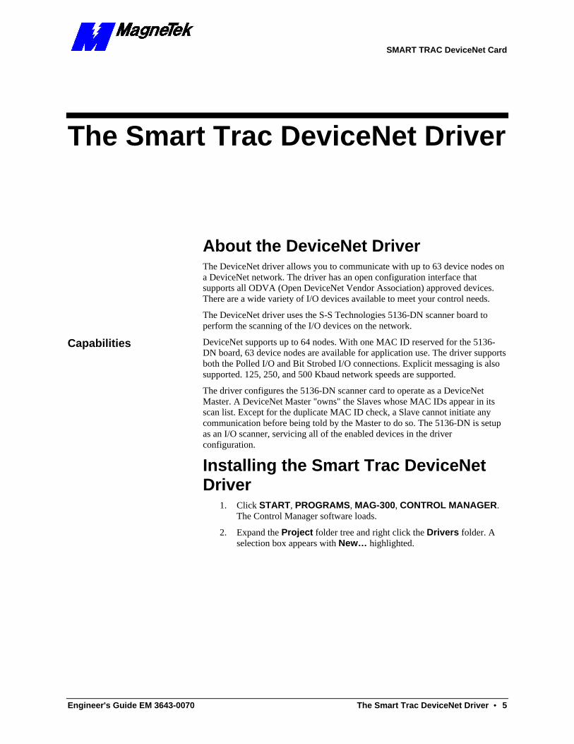
SMART TRAC DeviceNet Card
SMART TRAC DeviceNet Card
Engineer's Guide EM 3643-0070 Contents •• i
Contents
Important Safety and Warranty Information 3 Warnings, Cautions and Notes .....................................................................................................................3 General Safety Precautions - Warnings ......................................................................................................4 Important Warranty Information................................................................................................................4
The Smart Trac DeviceNet Driver 5 About the DeviceNet Driver..........................................................................................................................5
Capabilities........................................................................................................................................5 Installing the Smart Trac DeviceNet Driver ...............................................................................................5 Installing/Configuring devices on the DeviceNet network .........................................................................8
The Smart Trac DeviceNet Card 9 S-S Technologies 5136-DN Interface Card..................................................................................................9 Edit DeviceNet Nodes ..................................................................................................................................11 Using the Device Edit Dialog Box...............................................................................................................12 Stream Editor Dialog ..................................................................................................................................15 I/O Stream Edit Buttons .............................................................................................................................15 Stream Component Bit Edit Buttons .........................................................................................................16 Disable Edit Warning Messages Check Box .............................................................................................16 Using the Stream Component Edit Dialog ................................................................................................17 Explicit Messaging.......................................................................................................................................17
Configuring the driver for explicit messaging: ...............................................................................17 Scoped Tags..................................................................................................................................................18 CAN Bus Global Variables .........................................................................................................................18 Device Status Global Variables ..................................................................................................................22
<Symbol Name>_STATUS ............................................................................................................22
Technical Support 25 Getting Help.................................................................................................................................................25 Problem Report ...........................................................................................................................................26
Glossary of Terms 27
Index 29

SMART TRAC DeviceNet Card
THIS PAGE INTENTIONALLY LE3FT BLANK

SMART TRAC DeviceNet Card
Engineer's Guide EM 3643-0070 Important Safety and Warranty Information •• 3
Important Safety and Warranty Information
Warnings, Cautions and Notes
WARNING A statement of conditions which MUST BE OBSERVED to prevent personal injury or death.
WARNING - ESD A statement of conditions which must be observed to prevent damage to components due to ESD (ElectroStatic Discharge) and to prevent personal injury or death.
CAUTION A statement of conditions which must be observed to prevent undesired equipment faults, Smart Trac AC1 system degradation and damage to equipment.
IMPORTANT
A statement of conditions which should be observed during Smart Trac AC DeviceNet setup or operation to ensure dependable service.
NOTE: Notes indicate information that is in addition to a discussion of the topic in adjoining text. Alternatively, it may limit or restrict the paragraph(s) that follow(s) to specific models or conditions.
TIP - Tips indicate information that should make a procedure easier or more efficient.

SMART TRAC DeviceNet Card
4 •• Important Safety and Warranty Information Engineer's Guide EM 3643-0070
General Safety Precautions - Warnings Important safety information follows. Please read and understand all precautions listed below before proceeding with the specification, installation, set-up or operation of your Smart Trac AC1. Failure to follow any of the following precautions may result in personal injury or death, or damage to the equipment.
WARNING - ESD The Control Printed Circuit Board (PCB) employs CMOS Integrated Circuits that are easily damaged by static electricity. Use proper ElectroStatic Discharge (ESD) procedures when handling the Control PCB. See Smart Trac AC1 Technical Manual for details. Failure to comply may result in damage to equipment and/or personal injury.
Important Warranty Information. Do not modify your Smart Trac AC1, its components, or any of the procedures contained in the technical documentation supplied by MagneTek. Any modification of this product by the user is not the responsibility of MagneTek and will void the warranty.
SMART TRAC DeviceNet Card
Engineer's Guide EM 3643-0070 The Smart Trac DeviceNet Driver •• 5
The Smart Trac DeviceNet Driver
About the DeviceNet Driver The DeviceNet driver allows you to communicate with up to 63 device nodes on a DeviceNet network. The driver has an open configuration interface that supports all ODVA (Open DeviceNet Vendor Association) approved devices. There are a wide variety of I/O devices available to meet your control needs.
The DeviceNet driver uses the S-S Technologies 5136-DN scanner board to perform the scanning of the I/O devices on the network.
DeviceNet supports up to 64 nodes. With one MAC ID reserved for the 5136-DN board, 63 device nodes are available for application use. The driver supports both the Polled I/O and Bit Strobed I/O connections. Explicit messaging is also supported. 125, 250, and 500 Kbaud network speeds are supported.
The driver configures the 5136-DN scanner card to operate as a DeviceNet Master. A DeviceNet Master "owns" the Slaves whose MAC IDs appear in its scan list. Except for the duplicate MAC ID check, a Slave cannot initiate any communication before being told by the Master to do so. The 5136-DN is setup as an I/O scanner, servicing all of the enabled devices in the driver configuration.
Installing the Smart Trac DeviceNet Driver
1. Click START, PROGRAMS, MAG-300, CONTROL MANAGER. The Control Manager software loads.
2. Expand the Project folder tree and right click the Drivers folder. A selection box appears with New… highlighted.
Capabilities
SMART TRAC DeviceNet Card
6 •• The Smart Trac DeviceNet Driver Engineer's Guide EM 3643-0070
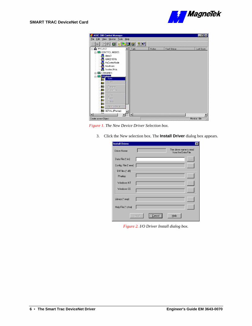
Figure 1. The New Device Driver Selection box.
3. Click the New selection box. The Install Driver dialog box appears.
Figure 2. I/O Driver Install dialog box.
SMART TRAC DeviceNet Card
Engineer's Guide EM 3643-0070 The Smart Trac DeviceNet Driver •• 7
To view driver .dll files, you must select View All Files in Windows NT Explorer. If you have Windows NT without IE4.0 installed: from Explorer, click View, Options, click View tab. In Hidden Files, click Show all files If you have IE4.0 installed: from Explorer, click View, Folder Options, click the View tab. In Advanced Settings, click Show All Files in the Hidden files folder.
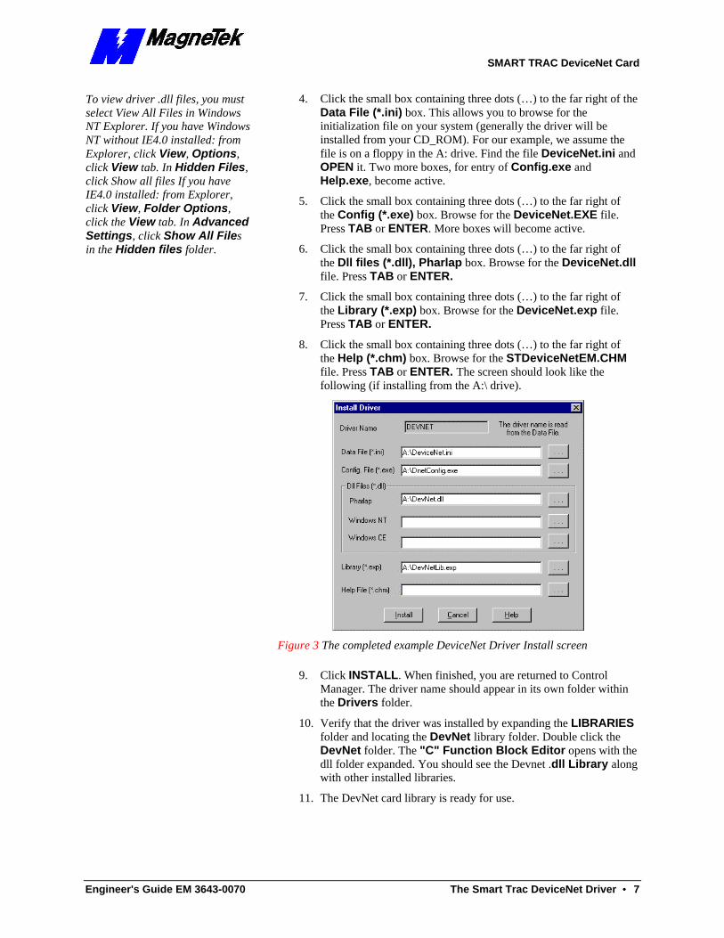
4. Click the small box containing three dots (…) to the far right of the Data File (*.ini) box. This allows you to browse for the initialization file on your system (generally the driver will be installed from your CD_ROM). For our example, we assume the file is on a floppy in the A: drive. Find the file DeviceNet.ini and OPEN it. Two more boxes, for entry of Config.exe and Help.exe, become active.
5. Click the small box containing three dots (…) to the far right of the Config (*.exe) box. Browse for the DeviceNet.EXE file. Press TAB or ENTER. More boxes will become active.
6. Click the small box containing three dots (…) to the far right of the Dll files (*.dll), Pharlap box. Browse for the DeviceNet.dll file. Press TAB or ENTER.
7. Click the small box containing three dots (…) to the far right of the Library (*.exp) box. Browse for the DeviceNet.exp file. Press TAB or ENTER.
8. Click the small box containing three dots (…) to the far right of the Help (*.chm) box. Browse for the STDeviceNetEM.CHM file. Press TAB or ENTER. The screen should look like the following (if installing from the A:\ drive).
Figure 3 The completed example DeviceNet Driver Install screen
9. Click INSTALL. When finished, you are returned to Control Manager. The driver name should appear in its own folder within the Drivers folder.
10. Verify that the driver was installed by expanding the LIBRARIES folder and locating the DevNet library folder. Double click the DevNet folder. The "C" Function Block Editor opens with the dll folder expanded. You should see the Devnet .dll Library along with other installed libraries.
11. The DevNet card library is ready for use.
SMART TRAC DeviceNet Card
8 •• The Smart Trac DeviceNet Driver Engineer's Guide EM 3643-0070
Installing/Configuring devices on the DeviceNet network Refer to the appropriate vendor's operator manual for each device for details on how to install the unit on the DeviceNet network. Be sure to set each device's MAC ID correctly to avoid addressing conflicts. Many simple devices are DIP switch configurable. However, more sophisticated devices are configured online via the network. Such devices require a DeviceNet management utility to be properly configured. It is recommended that you use a ODVA approved software package to configure your device. Contact your DeviceNet distributor for a list of network management software vendors.
SMART TRAC DeviceNet Card
Engineer's Guide EM 3643-0070 The Smart Trac DeviceNet Card •• 9
The Smart Trac DeviceNet Card
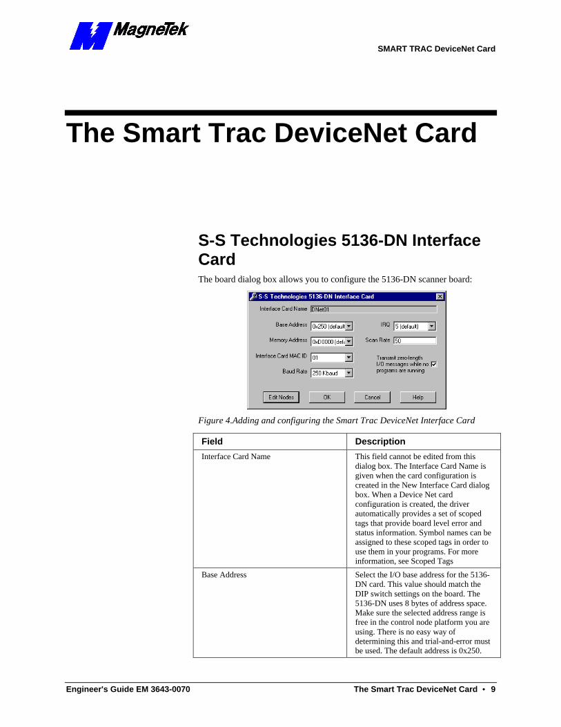
S-S Technologies 5136-DN Interface Card The board dialog box allows you to configure the 5136-DN scanner board:
Figure 4.Adding and configuring the Smart Trac DeviceNet Interface Card
Field Description
Interface Card Name
This field cannot be edited from this dialog box. The Interface Card Name is given when the card configuration is created in the New Interface Card dialog box. When a Device Net card configuration is created, the driver automatically provides a set of scoped tags that provide board level error and status information. Symbol names can be assigned to these scoped tags in order to use them in your programs. For more information, see Scoped Tags
Base Address
Select the I/O base address for the 5136-DN card. This value should match the DIP switch settings on the board. The 5136-DN uses 8 bytes of address space. Make sure the selected address range is free in the control node platform you are using. There is no easy way of determining this and trial-and-error must be used. The default address is 0x250.
SMART TRAC DeviceNet Card
10 •• The Smart Trac DeviceNet Card Engineer's Guide EM 3643-0070
Field Description
Memory Address
Select the 5136-DN shared RAM base address. The scanner card uses a 16K memory window. Make sure the selected address range is free in the control node platform you are using. There is no easy way of determining this and trial-and-error must be used. The default memory address is 0xD000.
IRQ
This driver does not use interrupts. It ignores this field.
Interface Card M~AC ID
Enter a DeviceNet MAC ID for the 5136-DN board. The 5136-DN requires a MAC ID to communicate on the network. Make sure the selected MAC ID is unused. This can be determined by tracking and examining IDs for all devices on the DeviceNet network. The default MAC ID is 00.
Baud Rate
Select the baud rate for the 5136-DN card. Make sure all the devices in the DeviceNet network are configured with the same baud rate.
Scan Rate
This is the frequency in milliseconds that 1) Input values from the device are written to control node memory, and 2) values from the control node memory are written to the device.
Transmit zero-length I/O messages while no programs are running Check Box
When this box is checked, the driver will transmit zero-length I/O messages while no programs are running. The receipt of zero-length I/O messages is interpreted by DeviceNet devices as a receive_idle event. The behavior of a device upon detection of the receive_idle event is vendor specific. An I/O message that contains data is interpreted as a run event by a device. The behavior of a device upon detection of the run event is vendor specific. A typical response to a receive_idle event is to disable all outputs. Refer to the device vendor 's operator manual to determine how your device responds to these events.
When this box is checked, the watchdog timer is enabled on the 5136-DN board. If, for any reason, the driver stops talking to the scanner card, the watchdog timer will expire. When the watchdog timer expires on the 5136-DN, the board will transmit zero-length messages to all connected devices.
Edit Nodes Button
Clicking on this button opens the Edit DeviceNet Nodes dialog box, which allows you to select and edit each of the devices in the network. For more information, see Edit DeviceNet Nodes.
SMART TRAC DeviceNet Card
Engineer's Guide EM 3643-0070 The Smart Trac DeviceNet Card •• 11
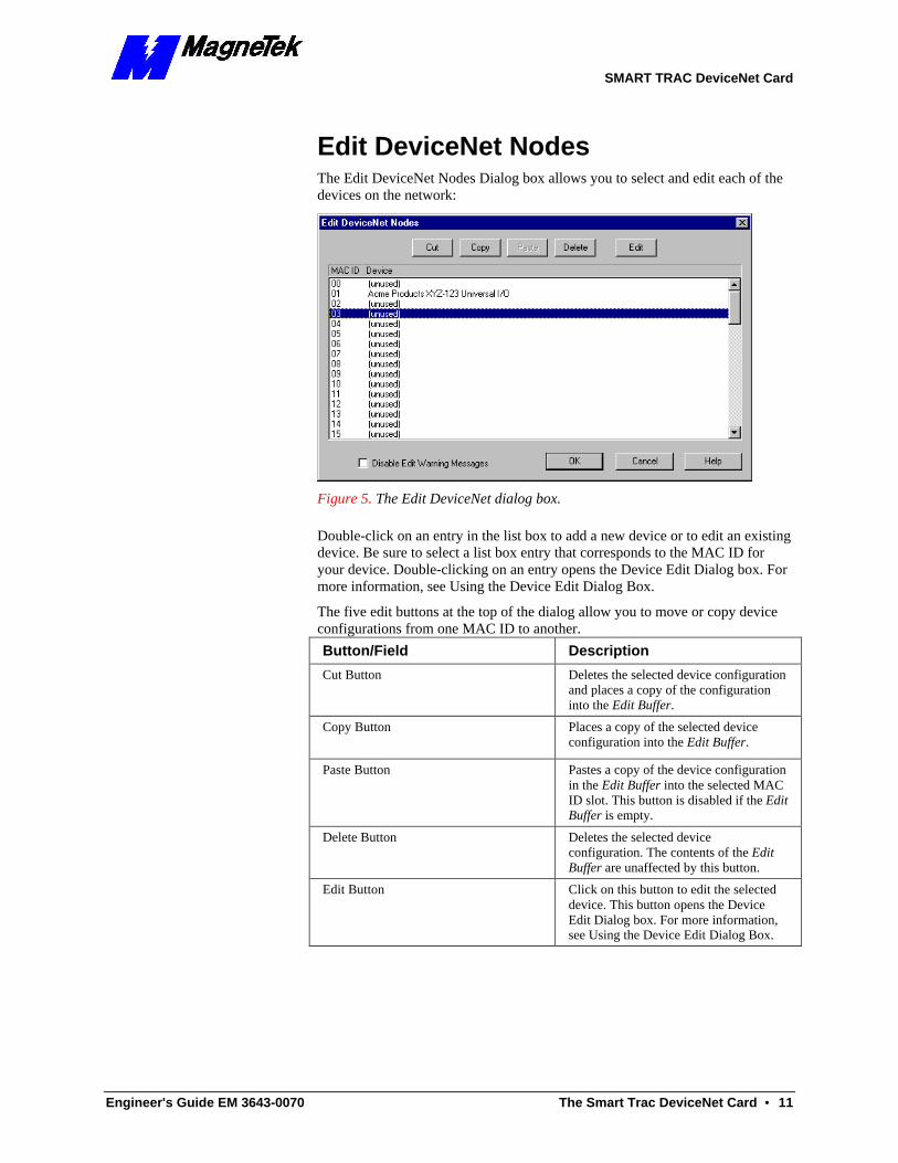
Edit DeviceNet Nodes The Edit DeviceNet Nodes Dialog box allows you to select and edit each of the devices on the network:
Figure 5. The Edit DeviceNet dialog box.
Double-click on an entry in the list box to add a new device or to edit an existing device. Be sure to select a list box entry that corresponds to the MAC ID for your device. Double-clicking on an entry opens the Device Edit Dialog box. For more information, see Using the Device Edit Dialog Box.
The five edit buttons at the top of the dialog allow you to move or copy device configurations from one MAC ID to another.
Button/Field Description
Cut Button
Deletes the selected device configuration and places a copy of the configuration into the Edit Buffer.
Copy Button
Places a copy of the selected device configuration into the Edit Buffer.
Paste Button
Pastes a copy of the device configuration in the Edit Buffer into the selected MAC ID slot. This button is disabled if the Edit Buffer is empty.
Delete Button
Deletes the selected device configuration. The contents of the Edit Buffer are unaffected by this button.
Edit Button
Click on this button to edit the selected device. This button opens the Device Edit Dialog box. For more information, see Using the Device Edit Dialog Box.
SMART TRAC DeviceNet Card
12 •• The Smart Trac DeviceNet Card Engineer's Guide EM 3643-0070
Button/Field Description
Disable Warning Messages
When this box is checked, all edit warning messages are disabled. Normally, edit warning messages are displayed when you use the Cut, Paste and Delete buttons.
Note that when you check this box, you disable edit warning messages in all the dialog boxes. The configuration system "remembers" the state of this check box as you navigate though the various configuration dialogs.
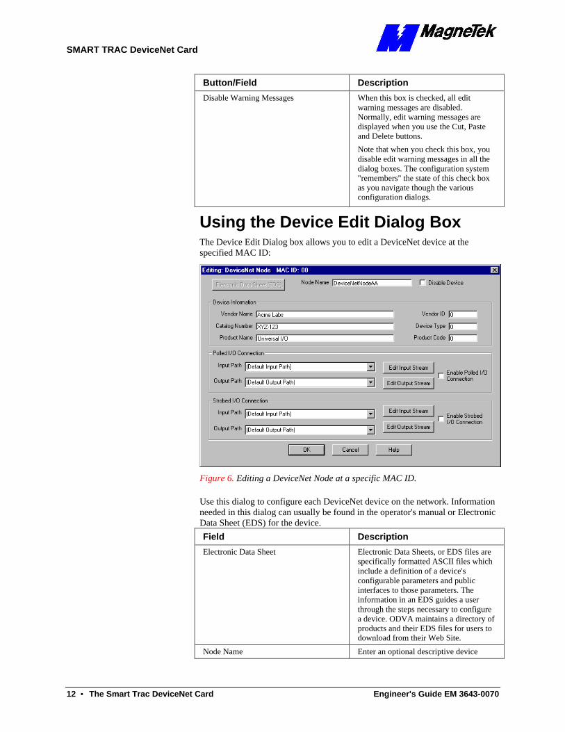
Using the Device Edit Dialog Box The Device Edit Dialog box allows you to edit a DeviceNet device at the specified MAC ID:
Figure 6. Editing a DeviceNet Node at a specific MAC ID.
Use this dialog to configure each DeviceNet device on the network. Information needed in this dialog can usually be found in the operator's manual or Electronic Data Sheet (EDS) for the device.
Field Description
Electronic Data Sheet Electronic Data Sheets, or EDS files are specifically formatted ASCII files which include a definition of a device's configurable parameters and public interfaces to those parameters. The information in an EDS guides a user through the steps necessary to configure a device. ODVA maintains a directory of products and their EDS files for users to download from their Web Site.
Node Name Enter an optional descriptive device name in this box. If a DeviceNet node
SMART TRAC DeviceNet Card
Engineer's Guide EM 3643-0070 The Smart Trac DeviceNet Card •• 13
Field Description name in this box. If a DeviceNet node name is entered, the driver will automatically provide a set of scoped tags that provide device level error and status information. For more information, refer to Scoped Tags.
Vendor Name, Catalog Number and Product Name
The Vendor Name, Catalog Number and Product Name are optional, and are provided to help you identify a device configuration. Enter the device manufacturers name in the Vendor Name edit box. The device catalog or model number should be entered into the Catalog Number edit box. Enter the device product name or description in the Product Name edit box.
Vendor ID, Device Type and Product Code
The Vendor ID, Device Type and Product Code are all optional, and default to zero. They can be used to uniquely identify a device on the network. When you provide non-zero values for the three entries, the 5136-DN card will query the device for the correct values, and if the values do not match, the device connection will fail. You can use this feature to insure that you are connecting to the correct type of device on the network. Refer to the Electronic Data Sheet (EDS) for the device for the correct values.
If you leave the Vendor ID, Device Type and Product Code at the default of zero, the 5136-DN will connect to the device without verifying it's device type. When using the defaults, the 5136-DN will ignore the three configuration parameters and it will not query the device for the correct values during connection setup.
Input Path and Output Path The I/O path specifies which device connection to use as a producer (input) or consumer (output). For devices which have a single input or output connection, using the default connection path is adequate. Most simple devices have single input and output connections.
For devices with multiple consuming or producing connections, you will need to enter a connection path for the device. Refer to the EDS sheet or the operator's manual for a list of available connection paths and associated I/O stream formats for your device.
A connection path consists of groups of two hexadecimal characters separated by spaces. An optional comment string, encased in parentheses, c~an be attached
SMART TRAC DeviceNet Card
14 •• The Smart Trac DeviceNet Card Engineer's Guide EM 3643-0070
Field Description to the end of the path. Here are some examples:
20 04 24 11 30 03
20 0E 24 01
20 04 24 12 30 03 (Data)
20 04 24 20 30 03 (Data + Status)
Edit Input Stream and Edit Output Stream Buttons
Use the Edit Input Stream and Edit Output Stream buttons to define the device's I/O stream and to attach symbolic information to each stream component. Refer to the operator's manual for the device to determine the exact format of the I/O stream. Clicking on an Edit I/O Stream button opens the I/O Stream Editor Dialog. For more information, see Stream Editor Dialog.
Enable Polled I/O Connection Check Box
Check this box to enable the Polled I/O connection. When enabled, the driver will establish a polled I/O connection to the specified device.
Enable Strobed I/O Connection Check Box
Check this box to enable the Bit Strobed I/O connection. When enabled, the driver will establish a strobed I/O connection to the specified device.
Edit Connection Button Click on this button to define the explicit message connection for this device. For more information, see Explicit Messaging below.
Enable Explicit Message Connection Check Box
Check this box to enable the explicit message connection. For more information, see Explicit Messaging below.
Disable Device Check Box Check this box to disable the device. When disabled, the driver will not connect to the device. You can use this option to disable a device without having to remove the device configuration.
NOTE: Bit Strobed devices have only one bit of output data. Clicking the Edit Output Stream button for this connection allows you to edit the symbol name for the output bit.
Stream Editor Dialog The I/O Stream Editor Dialog allows you to define the exact format of the input or output stream for the selected device. It also allows you to attach symbolic information to each stream component. The Polled Input Stream is shown; however, Polled Output Stream and the Strobed Input Stream are identical.
The upper list box displays the current I/O stream format. This includes the type and size of each stream component, and the symbolic name attached to each
SMART TRAC DeviceNet Card
Engineer's Guide EM 3643-0070 The Smart Trac DeviceNet Card •• 15
component, if defined. The "<End of I/O Stream>" tag marks the end of the I/O stream.
The lower list box displays the bit information for the selected (highlighted) stream component. The information in this list box includes the bit numbers and the symbolic information attached to each bit. If no stream component is selected in the top list box, or the selected stream component does not have editable bits, then the bottom list box is disabled (grayed-out).
To edit a stream component in the top list box, double-click on the desired component. The Stream Component Edit Dialog appears. This dialog allows you to assign a symbolic name for the selected stream component and define its type. The symbol name is optional for stream components. For more information, see Using the Stream Component Edit Dialog.
After you have finished editing the stream component, you can go to the bottom list box to edit the symbolic information for each bit of the stream component. Double-click on the desired bit entry to edit the symbol name. Symbol names are optional for the bits of a stream component.
Note that double-clicking on the <End of I/O Stream> tag allows you insert a new stream component at the end of the stream. Use the "Insert New" button to insert a new component anywhere in the I/O stream. You can use the edit buttons to cut/paste stream components.
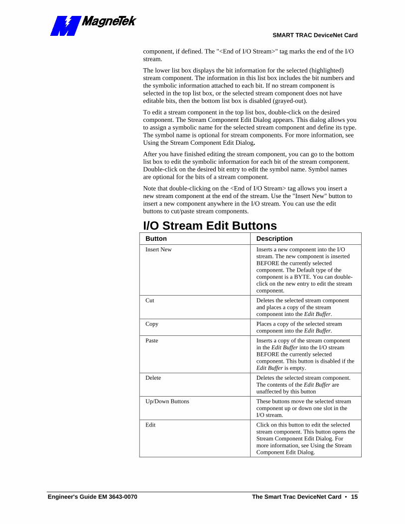
I/O Stream Edit Buttons Button Description
Insert New Inserts a new component into the I/O stream. The new component is inserted BEFORE the currently selected component. The Default type of the component is a BYTE. You can double-click on the new entry to edit the stream component.
Cut Deletes the selected stream component and places a copy of the stream component into the Edit Buffer.
Copy Places a copy of the selected stream component into the Edit Buffer.
Paste Inserts a copy of the stream component in the Edit Buffer into the I/O stream BEFORE the currently selected component. This button is disabled if the Edit Buffer is empty.
Delete Deletes the selected stream component. The contents of the Edit Buffer are unaffected by this button
Up/Down Buttons These buttons move the selected stream component up or down one slot in the I/O stream.
Edit Click on this button to edit the selected stream component. This button opens the Stream Component Edit Dialog. For more information, see Using the Stream Component Edit Dialog.
SMART TRAC DeviceNet Card
16 •• The Smart Trac DeviceNet Card Engineer's Guide EM 3643-0070
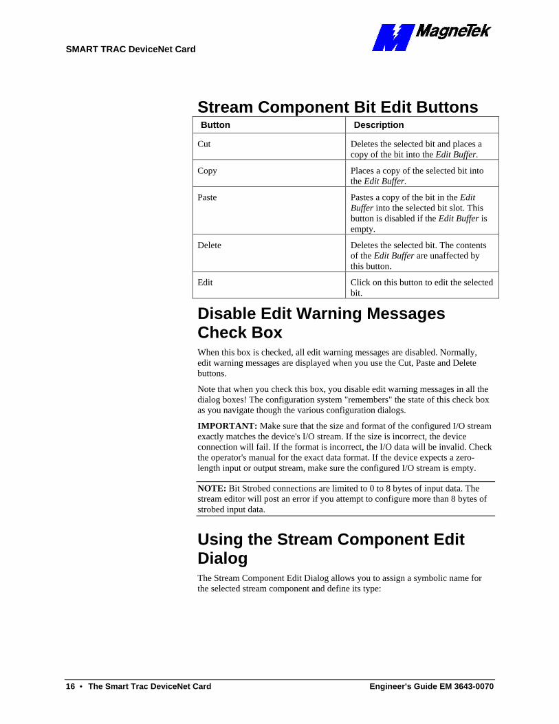
Stream Component Bit Edit Buttons Button Description
Cut Deletes the selected bit and places a copy of the bit into the Edit Buffer.
Copy Places a copy of the selected bit into the Edit Buffer.
Paste Pastes a copy of the bit in the Edit Buffer into the selected bit slot. This button is disabled if the Edit Buffer is empty.
Delete Deletes the selected bit. The contents of the Edit Buffer are unaffected by this button.
Edit Click on this button to edit the selected bit.
Disable Edit Warning Messages Check Box When this box is checked, all edit warning messages are disabled. Normally, edit warning messages are displayed when you use the Cut, Paste and Delete buttons.
Note that when you check this box, you disable edit warning messages in all the dialog boxes! The configuration system "remembers" the state of this check box as you navigate though the various configuration dialogs.
IMPORTANT: Make sure that the size and format of the configured I/O stream exactly matches the device's I/O stream. If the size is incorrect, the device connection will fail. If the format is incorrect, the I/O data will be invalid. Check the operator's manual for the exact data format. If the device expects a zero-length input or output stream, make sure the configured I/O stream is empty.
NOTE: Bit Strobed connections are limited to 0 to 8 bytes of input data. The stream editor will post an error if you attempt to configure more than 8 bytes of strobed input data.
Using the Stream Component Edit Dialog The Stream Component Edit Dialog allows you to assign a symbolic name for the selected stream component and define its type:
SMART TRAC DeviceNet Card
Engineer's Guide EM 3643-0070 The Smart Trac DeviceNet Card •• 17
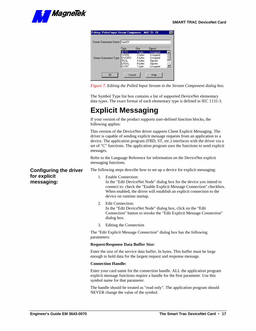
Figure 7. Editing the Polled Input Stream in the Stream Component dialog box.
The Symbol Type list box contains a list of supported DeviceNet elementary data types. The exact format of each elementary type is defined in IEC 1131-3.
Explicit Messaging If your version of the product supports user-defined function blocks, the following applies:
This version of the DeviceNet driver supports Client Explicit Messaging. The driver is capable of sending explicit message requests from an application to a device. The application program (FBD, ST, etc.) interfaces with the driver via a set of "C" functions. The application program uses the functions to send explicit messages.
Refer to the Language Reference for information on the DeviceNet explicit messaging functions.
The following steps describe how to set up a device for explicit messaging:
1. Enable Connection: In the "Edit DeviceNet Node" dialog box for the device you intend to connect to: check the "Enable Explicit Message Connection" checkbox. When enabled, the driver will establish an explicit connection to the device on runtime startup.
2. Edit Connection: In the "Edit DeviceNet Node" dialog box, click on the "Edit Connection" button to invoke the "Edit Explicit Message Connection" dialog box.
3. Editing the Connection
The "Edit Explicit Message Connection" dialog box has the following parameters:
Request/Response Data Buffer Size:
Enter the size of the service data buffer, In bytes. This buffer must be large enough to hold data for the largest request and response message.
Connection Handle:
Enter your card name for the connection handle. ALL the application program explicit message functions require a handle for the first parameter. Use this symbol name for that parameter.
The handle should be treated as "read only". The application program should NEVER change the value of the symbol.
Configuring the driver for explicit messaging:
SMART TRAC DeviceNet Card
18 •• The Smart Trac DeviceNet Card Engineer's Guide EM 3643-0070
Transaction Complete BOOL: Enter a valid symbol name for the Transaction Complete BOOL. If defined, the driver will set this BOOL to TRUE when an explicit request is complete and the response has been received.
4. Save and Activate Save and activate the configuration. As soon as the runtime system is up and running, the newly configured connection is available to the application program.
5. Write Application Program Write your application program using the explicit message interface functions to send explicit requests. The interface functions are described in detail below.
Scoped Tags When certain symbol names are defined in the DeviceNet configuration, the driver will automatically provide a set of global variables that will report status and error information. If a board name is provided, the driver will create a set of global variables that provide status and error information on the CAN bus. If a device symbol name is defined, then the driver will provide a variable that reports the status of the device.
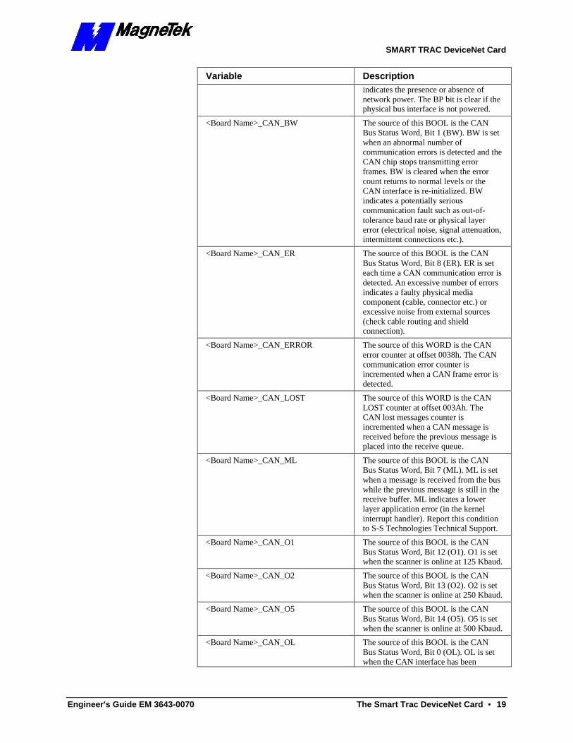
CAN Bus Global Variables If a board name is provided in the Board Dialog, the driver will automatically create a set of global variables that provide status and error information on the CAN bus. Symbolic information is appended to the end of the board name to create each global variable. Deleting the board name in the dialog disables the creation of these variables.
Variable Description
<Board Name>_CAN_A The source of this BOOL is the CAN Bus Status Word, Bit 3 (A). A is set when network activity has been detected (messages received or transmitted).
<Board Name>_CAN_ACK The source of this WORD is the CAN ack counter at offset 0034h. The CAN ack error counter is incremented when a transmit message is aborted due to lack of acknowledgment from other stations. When the CAN ack counter is incremented, the CAN TX counter is decremented to compensate for a message not actually transmitted.
<Board Name>_CAN_BO The source of this BOOL is the CAN Bus Status Word, Bit 2 (BO). BO is set when an excessive number of communication errors is detected and the CAN chip automatically goes off-line. BO is cleared when the CAN interface is re-initialized. BO indicates a serious communication fault such as incorrect baud rate or physical layer error (short, open etc).
<Board Name>_CAN_BP The source of this BOOL is the CAN Bus Status Word, Bit 9 (BP). The BP bit
SMART TRAC DeviceNet Card
Engineer's Guide EM 3643-0070 The Smart Trac DeviceNet Card •• 19
Variable Description indicates the presence or absence of network power. The BP bit is clear if the physical bus interface is not powered.
<Board Name>_CAN_BW The source of this BOOL is the CAN Bus Status Word, Bit 1 (BW). BW is set when an abnormal number of communication errors is detected and the CAN chip stops transmitting error frames. BW is cleared when the error count returns to normal levels or the CAN interface is re-initialized. BW indicates a potentially serious communication fault such as out-of-tolerance baud rate or physical layer error (electrical noise, signal attenuation, intermittent connections etc.).
<Board Name>_CAN_ER The source of this BOOL is the CAN Bus Status Word, Bit 8 (ER). ER is set each time a CAN communication error is detected. An excessive number of errors indicates a faulty physical media component (cable, connector etc.) or excessive noise from external sources (check cable routing and shield connection).
<Board Name>_CAN_ERROR The source of this WORD is the CAN error counter at offset 0038h. The CAN communication error counter is incremented when a CAN frame error is detected.
<Board Name>_CAN_LOST The source of this WORD is the CAN LOST counter at offset 003Ah. The CAN lost messages counter is incremented when a CAN message is received before the previous message is placed into the receive queue.
<Board Name>_CAN_ML The source of this BOOL is the CAN Bus Status Word, Bit 7 (ML). ML is set when a message is received from the bus while the previous message is still in the receive buffer. ML indicates a lower layer application error (in the kernel interrupt handler). Report this condition to S-S Technologies Technical Support.
<Board Name>_CAN_O1 The source of this BOOL is the CAN Bus Status Word, Bit 12 (O1). O1 is set when the scanner is online at 125 Kbaud.
<Board Name>_CAN_O2 The source of this BOOL is the CAN Bus Status Word, Bit 13 (O2). O2 is set when the scanner is online at 250 Kbaud.
<Board Name>_CAN_O5 The source of this BOOL is the CAN Bus Status Word, Bit 14 (O5). O5 is set when the scanner is online at 500 Kbaud.
<Board Name>_CAN_OL The source of this BOOL is the CAN Bus Status Word, Bit 0 (OL). OL is set when the CAN interface has been
SMART TRAC DeviceNet Card
20 •• The Smart Trac DeviceNet Card Engineer's Guide EM 3643-0070
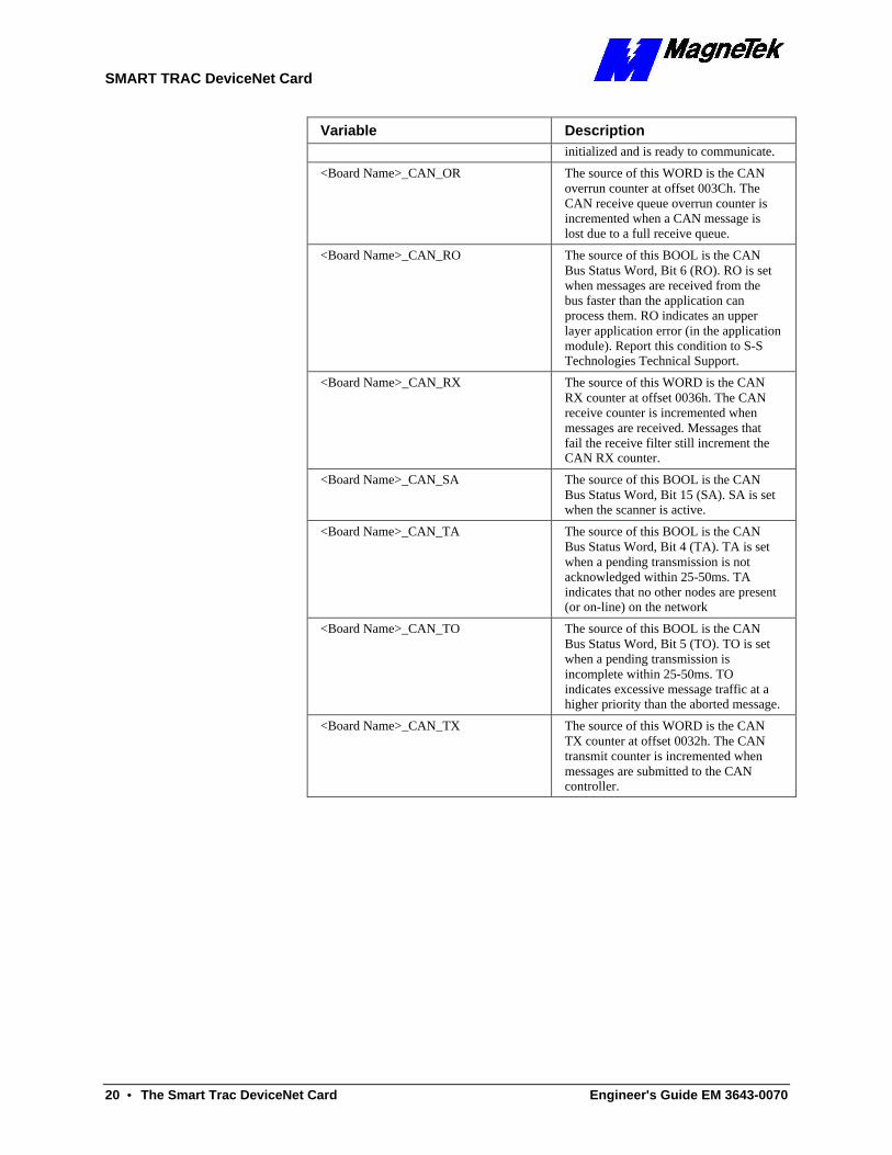
Variable Description initialized and is ready to communicate.
<Board Name>_CAN_OR The source of this WORD is the CAN overrun counter at offset 003Ch. The CAN receive queue overrun counter is incremented when a CAN message is lost due to a full receive queue.
<Board Name>_CAN_RO The source of this BOOL is the CAN Bus Status Word, Bit 6 (RO). RO is set when messages are received from the bus faster than the application can process them. RO indicates an upper layer application error (in the application module). Report this condition to S-S Technologies Technical Support.
<Board Name>_CAN_RX The source of this WORD is the CAN RX counter at offset 0036h. The CAN receive counter is incremented when messages are received. Messages that fail the receive filter still increment the CAN RX counter.
<Board Name>_CAN_SA The source of this BOOL is the CAN Bus Status Word, Bit 15 (SA). SA is set when the scanner is active.
<Board Name>_CAN_TA The source of this BOOL is the CAN Bus Status Word, Bit 4 (TA). TA is set when a pending transmission is not acknowledged within 25-50ms. TA indicates that no other nodes are present (or on-line) on the network
<Board Name>_CAN_TO The source of this BOOL is the CAN Bus Status Word, Bit 5 (TO). TO is set when a pending transmission is incomplete within 25-50ms. TO indicates excessive message traffic at a higher priority than the aborted message.
<Board Name>_CAN_TX The source of this WORD is the CAN TX counter at offset 0032h. The CAN transmit counter is incremented when messages are submitted to the CAN controller.
SMART TRAC DeviceNet Card
Engineer's Guide EM 3643-0070 The Smart Trac DeviceNet Card •• 21
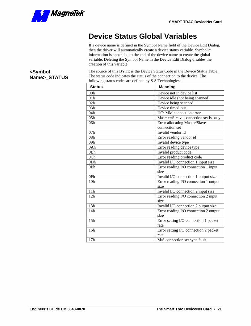
Device Status Global Variables If a device name is defined in the Symbol Name field of the Device Edit Dialog, then the driver will automatically create a device status variable. Symbolic information is appended to the end of the device name to create the global variable. Deleting the Symbol Name in the Device Edit Dialog disables the creation of this variable.
The source of this BYTE is the Device Status Code in the Device Status Table. The status code indicates the status of the connection to the device. The following status codes are defined by S-S Technologies:
Status Meaning
00h Device not in device list 01h Device idle (not being scanned) 02h Device being scanned 03h Device timed-out 04h UC~MM connection error 05h Mas~ter/Sl~ave connection set is busy 06h Error allocating Master/Slave
connection set 07h Invalid vendor id 08h Error reading vendor id 09h Invalid device type 0Ah Error reading device type 0Bh Invalid product code 0Ch Error reading product code 0Dh Invalid I/O connection 1 input size 0Eh Error reading I/O connection 1 input
size 0Fh Invalid I/O connection 1 output size 10h Error reading I/O connection 1 output
size 11h Invalid I/O connection 2 input size 12h Error reading I/O connection 2 input
size 13h Invalid I/O connection 2 output size 14h Error reading I/O connection 2 output
size 15h Error setting I/O connection 1 packet
rate 16h Error setting I/O connection 2 packet
rate 17h M/S connection set sync fault
<Symbol Name>_STATUS

SMART TRAC DeviceNet Card
22 •• The Smart Trac DeviceNet Card Engineer's Guide EM 3643-0070
THIS PAGE INTENTIONALLY LEFT BLANK

SMART TRAC DeviceNet Card
Engineer's Guide EM 3643-0070 Technical Support •• 23
Technical Support
Getting Help Should you need technical assistance with installation or troubleshooting of your Smart Trac AC1, you can phone our Help Desk at either (800)-541-0939 or (262)-782-0200. Alternatively, you may copy the Problem Report form, found on the next page, and fax it to us at (262)-782-3418.

SMART TRAC DeviceNet Card
24 •• Technical Support Engineer's Guide EM 3643-0070
Problem Report Name:
Address:
City: State: Zip
Software Version: DeviceNet Driver
Occurrence: Frequently Intermittantly Rarely
Nature of Problem:
Conditions when problem occurs:
SMART TRAC DeviceNet Card
Engineer's Guide EM 3643-0070 Glossary of Terms •• 25
Glossary of Terms
A bit strobed I/O connection is designed to move small amounts of I/O data between a Master and its bitstrobed slaves rapidly and efficiently. Bit strobed I/O connections are limited to 1 bit of output and up to 8 bytes of input data.
The Bus refers to the DeviceNet network. Specifically, the physical media that carries the network signals, as well as the network power.
CAN (Controller Area Network) is a communications protocol specification which defines the following:
· A Media Access Control (MAC) methodology
· Physical Signaling
The edit buffer refers to the DeviceNet driver's Cut/Paste clip board buffer. Cutting or copying an object places a copy of the object into the edit buffer. The contents of the buffer c~an then be pasted elsewhere in the configuration.
Electronic Data Sheets, or EDS files are specifically formatted ASCII files which include a definition of a device's configurable parameters and public interfaces to those parameters. The information in an EDS guides a user through the steps necessary to configure a device. ODVA maintains a directory of products and their EDS files for users to download from their Web Site.
See EDS.
Explicit Messaging Connections provide generic, multipurpose communication paths between two devices. Explicit Messages are exchanged across Explicit Messaging Connections. Explicit Messages are used to command the performance of a particular task and to report the results of performing the task. Explicit Messaging provides the means by which typical request/response oriented functions are performed (e.g. module configuration).
The produced connection path (input path) is made up of a byte stream which defines which of a device's application object(s) to connect to. This application object produces data that is input by the driver.
Bit Strobed I/O
bus
CAN bus
Edit Buffer
EDS
Electronic Data Sheet Explicit Messaging
I/O path
SMART TRAC DeviceNet Card
26 •• Glossary of Terms Engineer's Guide EM 3643-0070
The consumed connection path (output path) is made up of a byte stream that defines which of a device's application object(s) to connect to. This application object consumes data that is output by the driver.
The Media Access Control Identifier (MAC ID) is an integer identification value assigned to each node on a DeviceNet network. This value distinguishes a node from all the other nodes on the same link.
The Master is the device that gathers and distributes I/O data for the process controller. Slaves are the devices from which the Master gathers I/O data and to which the Master distributes I/O data.
The Master "owns" the Slaves who's MAC IDs appear in its scan list. To determine with what Slaves it will communicate, the Master examines its scan list and sends commands accordingly. Except for the Duplicate MAC ID Check, a Slave cannot initiate any communication before being told by the Master to do so.
A DeviceNet Node is a physical device attached to the network. Each node of a DeviceNet network has a unique MAC ID. DeviceNet supports up to 64 nodes.
Points of connection in a network.
ODVA is the Open DeviceNet Vendor Association, Inc. ODVA is an independent supplier organization that manages the DeviceNet specification and supports the worldwide growth of DeviceNet. ODVA also works with vendors by providing developer training, test software to assist developers, conformance testing services and marketing activities. ODVA publishes the DeviceNet product catalog and supports vendor Special Interest Groups in developing Device Profiles for specific classes of products.
Polled I/O is designed to move any amount of I/O data between a master and its polled slaves, whereas Bit-Strobed I/O is designed to move only small amounts of I/O data between a master and its slaves.
See Master.
MAC ID
Master
node
nodes ODVA
Polled I/O
Slave
SMART TRAC DeviceNet Card
Engineer's Guide EM 3643-0070 Index •• 27
Index
5
5136-DN scanner board 5, 9–10, 13
B
Bit Strobed I/O 5, 14
C
CAN Bus Global Variables 18 configuration 8–9, 12, 16
D
Device Edit 11–12, 21 Device Status Code 21 Device Status Global Variables 21 DeviceNet Master 5 Disable Edit Warning Messages
Check Box 16
E
edit, buttons 11, 15–16 Edit, Device 11–12, 21 Edit, Stream Component 15 Editing DeviceNet Nodes 10–11 Explicit messaging 5, 14, 17
I
I/O Stream Edit Buttons 15 I/O stream format 14 Installing 6–8 Installing the Smart Trac
DeviceNet Driver 5
L
Language Reference 17
M
MAC ID 5, 8, 10–12
N
network speeds 5
P
Polled I/O 5, 14 Polled Input Stream 14 Polled Output Stream 14
S
scanning 5 Scoped Tags 9, 12, 18 Slave 5, 21 Stream Component Bit Edit
Buttons 16 Stream Component Edit 15 Stream Editor Dialog 14 Strobed Input Stream 14

SMART TRAC DeviceNet Card
Data subject to change without notice. Smart Trac is a trademark of MagneTek, Inc. MicroTrac is a registered trademark of MagneTek, Inc. Microsoft, Windows and Windows NT are registered trademarks of Microsoft Corporation
MagneTek Drives and Systems 16555 West Ryerson Road New Berlin, WI 53151 (800) 541-0939, (262) 782-0200, FAX (262) 782-3418
EM 3643-0070 © 1999-2000 MagneTek, Inc. 1/31/2000