Embed Size (px)
Citation preview
Nuclear-1 EIA Specialist Study for EIR Geotechnical Characterisation Assessment Study i Final / March 2011
ENVIRONMENTAL IMPACT ASSESSMENT FOR A PROPOSED NUCLEAR POWER STATION (‘NUCLEAR-1’) AND ASSOCIATED
INFRASTRUCTURE
Geotechnical Characterisation Assessment Study
March 2011
Prepared by: SRK Consulting (SA) (Pty) Ltd Prepared for: Arcus GIBB Pty Ltd On behalf of: Eskom Holdings Ltd
Nuclear-1 EIA Specialist Study for EIR Geotechnical Characterisation Assessment Study ii Final / March 2011
March 2011
DECLARATION OF INDEPENDENCE
I, Bruce Engelsman as duly authorised representative of __SRK Consulting SA (Pty) Ltd,
hereby confirm my independence (as well as that of SRK Consulting SA (Pty) Ltd__ as a
specialist and declare that neither I nor SRK Consulting SA (Pty) Ltd have any interest, be it
business, financial, personal or other, in any proposed activity, application or appeal in
respect of which Arcus GIBB was appointed as environmental assessment practitioner in
terms of the National Environmental Management Act, 1998 (Act No. 107 of 1998), other
than fair remuneration for worked performed, specifically in connection with the
Environmental Impact Assessment for the proposed conventional nuclear power station
(‘Nuclear-1’). I further declare that I am confident in the results of the studies undertaken and
conclusions drawn as a result of it – as is described in my attached report.
Full Name: Bruce Engelsman
Title / Position: Pr Eng Pr CPM / Associate
Qualification(s): BSc Eng (Civil)
Experience (years/ months): 16 Years
Registration(s): Pr Eng Pr CPM
The Administrative Building Albion Spring, 183 Main Road Rondebosch 7700 PostNet Suite #206 Private Bag X18 Rondebosch 7701
South Africa e-Mail: [email protected] www.srk.co.za Tel: +27 (0) 21 659 3060
Fax: +27 (0) 21 685 7105
Nuclear-1 EIA Specialist Study for EIR Geotechnical Characterisation Assessment Study iii Final / March 2011
EXECUTIVE SUMMARY
Eskom Holdings Limited (Eskom) proposes to construct Nuclear Power Stations and associated infrastructure, either in the Eastern or Western Cape Province. Three site alternatives are considered: • Thyspunt (Eastern Cape – West of Port Elizabeth near Oyster Bay) • Bantamsklip (Western Cape – 5 km south-east of Pearly Beach) • Duynefontein (Western Cape – adjacent to the existing Koeberg Power
Station, Cape Town) The choice of suitable sites will be influenced by the Environmental Impact Assessment (EIA) process, in terms of which numerous physical, biophysical, oceanographical and engineering aspects are being investigated. This report considers the Geotechnical Engineering aspects of the sites. The report is based on a desk study of historical information as well as on extensive data gathered through intrusive field investigations. These data sources have identified the following fundamental geotechnical characteristics at the sites: • Thyspunt site:
o The site soil profile varies considerably in thickness as one moves inland, ranging from 0 m thick (at the sea) to almost 60 m thick within the dune area;
o The geotechnical properties of these soils are consistent across the site and random calcrete zones are encountered;
o An intergranular aquifer exists at the site, the groundwater table daylights at the sea and there is a variance in depth to the groundwater table in the dune area;
o The soils have no cohesion and when saturated, will require innovative slope stabilisation techniques for any proposed excavations;
o Two dominant geological formations are encountered under the soils, namely the Skurweberg and Goudini formations;
o The Skurweberg Formation is located nearer the sea and the Goudini Formation more inland;
o The quartzitic sandstone Skurweberg Formation is marginally more competent (harder and more resistant to erosion) than the carbonaceous sandstone Goudini Formation;
o An historical erosion depression containing cobbles exists in the Goudini Formation and this cobble layer influences groundwater flow direction in a South Easterly direction.
• Bantamsklip site:
o The site soil profile varies less in thickness than the Thyspunt site as one moves inland, ranging from 0 m thick (at the sea) to almost 20 m thick within the dune area;
o The geotechnical properties of these soils are consistent across the site and significant calcretised zones are encountered;
o The groundwater table is situated just above the bedrock; o The soils have no cohesion and when saturated, will require innovative
slope stabilisation techniques for any proposed excavations, but the presence of calcrete will provide some assistance in this regard;
Nuclear-1 EIA Specialist Study for EIR Geotechnical Characterisation Assessment Study iv Final / March 2011
o The bedrock is dominated by quartzitic sandstones of the Peninsula Formation;
o These quartzitic sandstones are highly jointed, but competent and present a more competent wave cut platform than at Thyspunt;
• Duynefontein site:
o The site soil profile differs from Thyspunt and Bantamsklip in that it is almost homogeneously 20 m thick everywhere on the site;
o The geotechnical properties of these soils are relatively consistent across the site;
o The groundwater table is elevated on this site and occurs between 4 and 10 m below natural ground level;
o The soils have no cohesion and when saturated, will require innovative slope stabilisation techniques for any proposed excavations;
o The overburden sands are underlain by Malmesbury rocks consisting of a succession of greywacke, hornfels, mudstone, siltsone and shale, all of varying competence;
o The greywacke and hornfels are more competent than the mudstone, siltstone and shale, which are all more prone to weathering.
• No go option
Should it be decided to not construct a nuclear power station none of the above impacts associated with construction of a nuclear power station will be introduced. All associated negative impacts will therefore be removed. However, Eskom could sell the Thyspunt and Bantamsklip sites, and possibly parts of the Duynefontein site under this scenario and there could therefore be other unforeseen negative impacts arising from different property development scenarios. Environmental impacts that could alter the functioning of the natural geotechnical environment are related to: • Slope instability in rocks and soils during and post construction resulting in
safety risks to people and to a lesser extent the environment; • Geotechnical conditions (and specifically overburden thickness and
groundwater profiles) dictating that large site disturbances will occur in excavations (that will need to be battered back to angles in the range of 20º);
• The disposal of excavation spoil. The impacts related to slope stability imposing safety risks without mitigation measures have low significance at all of the sites, as slope stability design techniques will be employed to deal with these issues. Standard slope stabilisation techniques in sands will almost certainly mean that excavated slopes will need to be battered back to flat angles (i.e. cut back to acute angles in the range of 20º) to limit the potential for slope failure. This leads to the overriding impact (resulting from flat slope angles) of larger volume excavations being required, leading to larger excavation footprint disturbances and a need for disposal of greater volumes of spoil. The impacts associated with this (without mitigation) are of medium significance at Duynefontein and Thyspunt and low significance at B antamsklip. With mitigation, which essentially involves locating the excavations near the sea at Bantamsklip and Thyspunt, the significance of assoc iated impacts are reduced to low and low – medium at Duynefontein and Thyspun t respectively. At Bantamsklip, the significance of these impacts are low – corresponding to less overburden on this site. Site sensitivity maps depicting the significance of these excavation related impacts are presented in this report.
Nuclear-1 EIA Specialist Study for EIR Geotechnical Characterisation Assessment Study v Final / March 2011
ENVIRONMENTAL IMPACT ASSESSMENT FOR THE PROPOSED NUCLEAR POWER STATION (“NUCLEAR-1”) AND ASSOCIATED
INFRASTRUCTURE GEOTECHNICAL CHARACTERISATION
CONTENTS
Chapter Description Page
1 INTRODUCTION 1
1.1 Background 1
1.1.1 Study Area 2
1.2 Study Approach 2
1.2.1 Assumptions and Limitations 4
1.3 Legislative Framework 4
1.4 Information Sources 5
1.5 Integration with other Studies 5
2 DESCRIPTION OF AFFECTED ENVIRONMENT 6
2.1 Thyspunt Site 6
2.1.1 Location and General Description 6
2.1.2 Geology 6
2.1.3 Regional Geohydrology 7
2.1.4 Seismology 7
2.1.5 Liquefaction Potential 7
2.1.6 Geotechnical Characterisation 9
2.1.7 Evaluation of site sensitivity 14
2.2 Bantamsklip Site 16
2.2.1 Location and General Description 16
2.2.2 Geology 16
2.2.3 Regional Geohydrology 17
2.2.4 Seismology 17
2.2.5 Liquefaction Potential 17
2.2.6 Geotechnical Characterisation 17
2.2.7 Evaluation of site sensitivity 21
2.3 Duynefontein Site 23
2.3.1 Location and General Description 23
2.3.2 Geology 23
2.3.3 Regional Geohydrology 25
2.3.4 Seismology 25
2.3.5 Liquefaction Potential 25
2.3.6 Geotechnical Characterisation 25
Nuclear-1 EIA Specialist Study for EIR Geotechnical Characterisation Assessment Study vi Final / March 2011
2.3.7 Evaluation of site sensitivity 30
3 IMPACT IDENTIFICATION AND ASSESSMENT 32
3.1 Potential Environmental Impacts 32
3.2 Geographical Significance 33
3.2.1 Thyspunt 33
3.2.2 Bantamsklip 34
3.2.3 Duynefontein 35
4 ENVIRONMENTAL ASSESSMENT 36
4.1 Construction Phase 36
4.2 Operational Phase 37
4.3 Decommissioning Phase 37
4.4 No-go Alternative 37
5 MITIGATION MEASURES 39
5.1 Mitigation objectives 39
5.1.1 Slope stability 39
5.1.2 Site disturbance 39
5.2 Recommended mitigation measures 39
5.2.1 Slope stability 39
5.2.2 Site disturbance 40
5.2.3 Effectiveness of mitigation measures 40
5.2.4 Recommended monitoring and evaluation programme 40
6 CONCLUSIONS AND RECOMMENDATIONS 41
6.1 Conclusions 41
6.2 Recommendations 43
7 REFERENCES 44
Nuclear-1 EIA Specialist Study for EIR Geotechnical Characterisation Assessment Study vii Final / March 2011
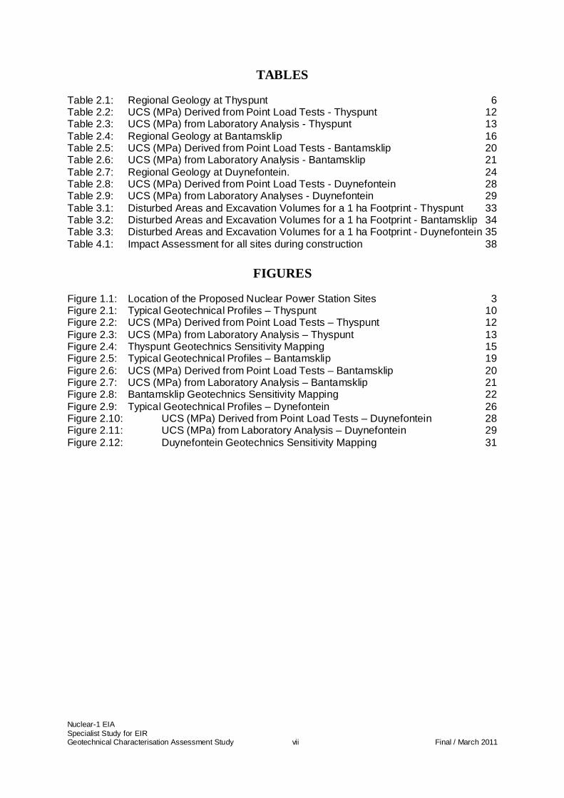
TABLES Table 2.1: Regional Geology at Thyspunt 6
Table 2.2: UCS (MPa) Derived from Point Load Tests - Thyspunt 12
Table 2.3: UCS (MPa) from Laboratory Analysis - Thyspunt 13
Table 2.4: Regional Geology at Bantamsklip 16
Table 2.5: UCS (MPa) Derived from Point Load Tests - Bantamsklip 20
Table 2.6: UCS (MPa) from Laboratory Analysis - Bantamsklip 21
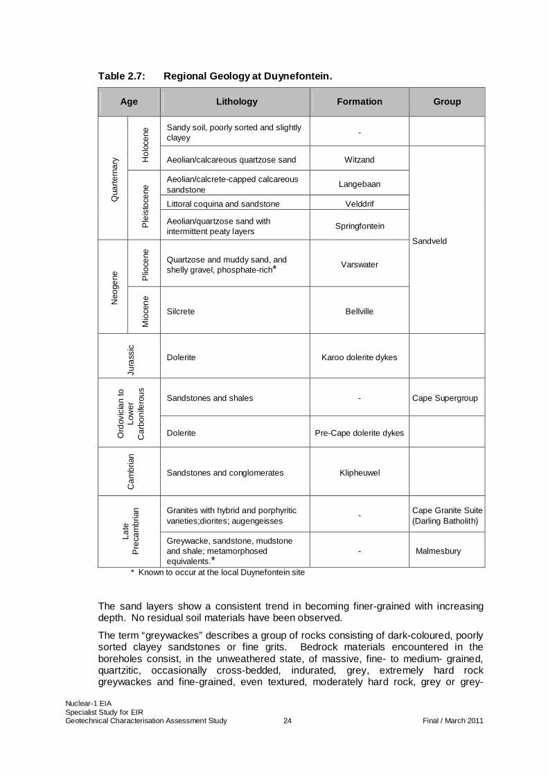
Table 2.7: Regional Geology at Duynefontein. 24
Table 2.8: UCS (MPa) Derived from Point Load Tests - Duynefontein 28
Table 2.9: UCS (MPa) from Laboratory Analyses - Duynefontein 29
Table 3.1: Disturbed Areas and Excavation Volumes for a 1 ha Footprint - Thyspunt 33
Table 3.2: Disturbed Areas and Excavation Volumes for a 1 ha Footprint - Bantamsklip 34
Table 3.3: Disturbed Areas and Excavation Volumes for a 1 ha Footprint - Duynefontein 35
Table 4.1: Impact Assessment for all sites during construction 38
FIGURES
Figure 1.1: Location of the Proposed Nuclear Power Station Sites 3
Figure 2.1: Typical Geotechnical Profiles – Thyspunt 10
Figure 2.2: UCS (MPa) Derived from Point Load Tests – Thyspunt 12
Figure 2.3: UCS (MPa) from Laboratory Analysis – Thyspunt 13
Figure 2.4: Thyspunt Geotechnics Sensitivity Mapping 15
Figure 2.5: Typical Geotechnical Profiles – Bantamsklip 19
Figure 2.6: UCS (MPa) Derived from Point Load Tests – Bantamsklip 20
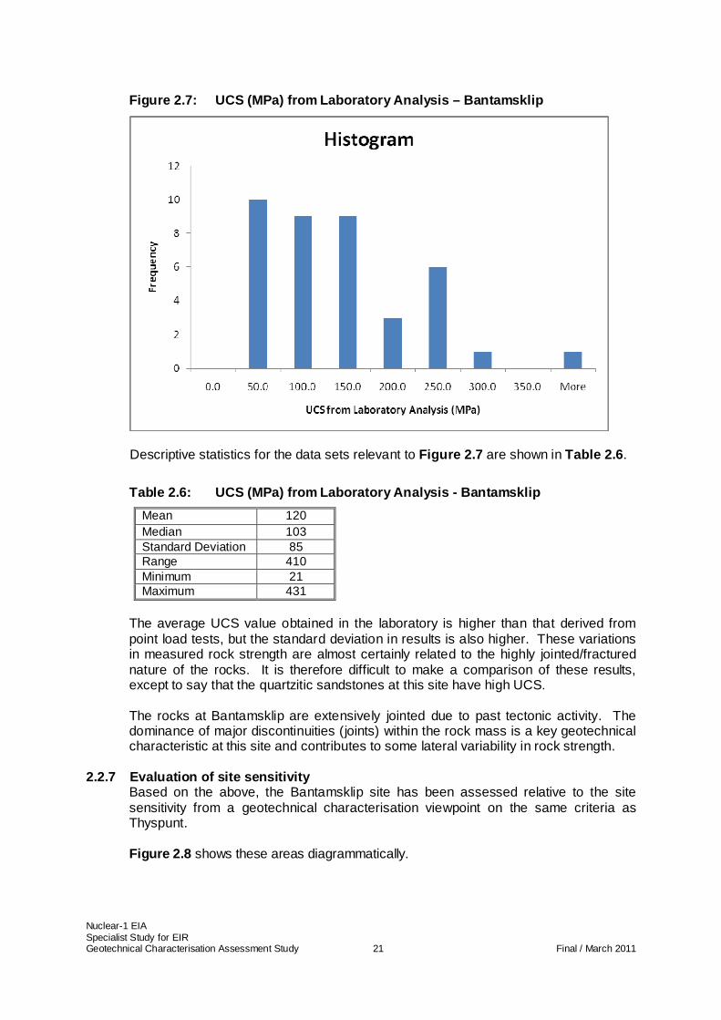
Figure 2.7: UCS (MPa) from Laboratory Analysis – Bantamsklip 21
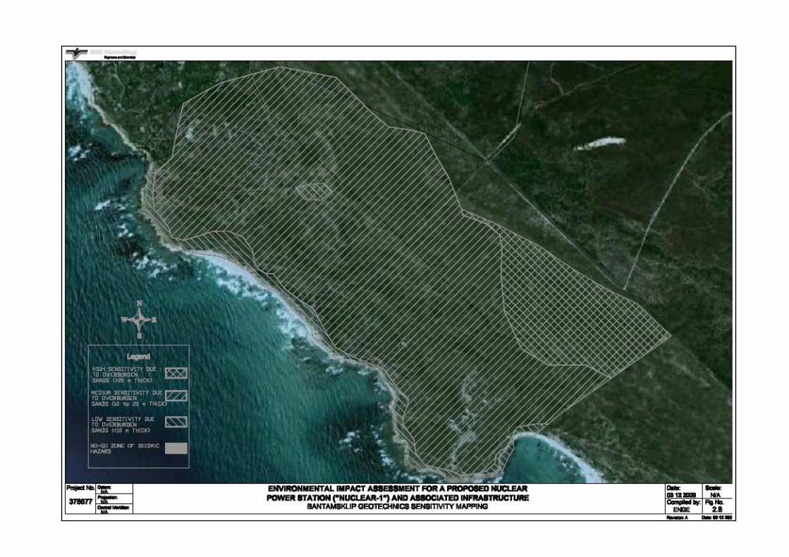
Figure 2.8: Bantamsklip Geotechnics Sensitivity Mapping 22
Figure 2.9: Typical Geotechnical Profiles – Dynefontein 26
Figure 2.10: UCS (MPa) Derived from Point Load Tests – Duynefontein 28
Figure 2.11: UCS (MPa) from Laboratory Analysis – Duynefontein 29
Figure 2.12: Duynefontein Geotechnics Sensitivity Mapping 31
Nuclear-1 EIA Specialist Study for EIR Geotechnical Characterisation Assessment Study viii Final / March 2011
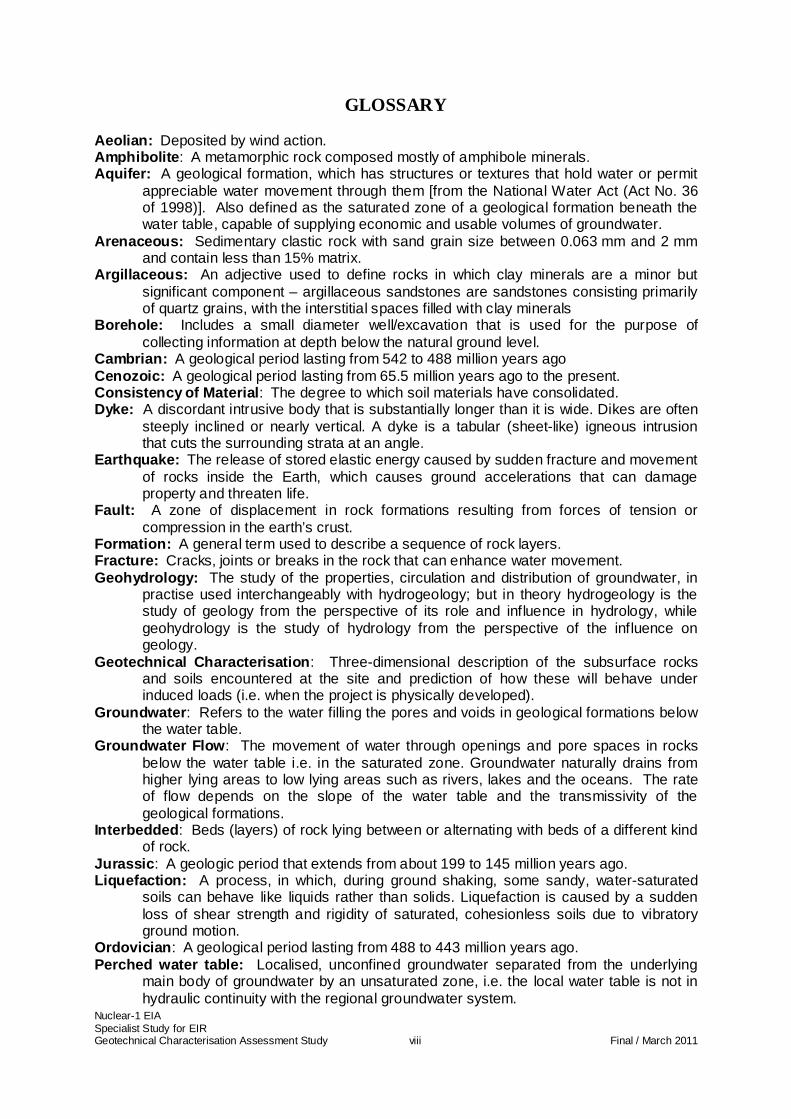
GLOSSARY Aeolian: Deposited by wind action. Amphibolite : A metamorphic rock composed mostly of amphibole minerals. Aquifer: A geological formation, which has structures or textures that hold water or permit
appreciable water movement through them [from the National Water Act (Act No. 36 of 1998)]. Also defined as the saturated zone of a geological formation beneath the water table, capable of supplying economic and usable volumes of groundwater.
Arenaceous: Sedimentary clastic rock with sand grain size between 0.063 mm and 2 mm and contain less than 15% matrix.
Argillaceous: An adjective used to define rocks in which clay minerals are a minor but significant component – argillaceous sandstones are sandstones consisting primarily of quartz grains, with the interstitial spaces filled with clay minerals
Borehole: Includes a small diameter well/excavation that is used for the purpose of collecting information at depth below the natural ground level.
Cambrian: A geological period lasting from 542 to 488 million years ago Cenozoic: A geological period lasting from 65.5 million years ago to the present. Consistency of Material : The degree to which soil materials have consolidated. Dyke: A discordant intrusive body that is substantially longer than it is wide. Dikes are often
steeply inclined or nearly vertical. A dyke is a tabular (sheet-like) igneous intrusion that cuts the surrounding strata at an angle.
Earthquake: The release of stored elastic energy caused by sudden fracture and movement of rocks inside the Earth, which causes ground accelerations that can damage property and threaten life.
Fault: A zone of displacement in rock formations resulting from forces of tension or compression in the earth’s crust.
Formation: A general term used to describe a sequence of rock layers. Fracture: Cracks, joints or breaks in the rock that can enhance water movement. Geohydrology: The study of the properties, circulation and distribution of groundwater, in
practise used interchangeably with hydrogeology; but in theory hydrogeology is the study of geology from the perspective of its role and influence in hydrology, while geohydrology is the study of hydrology from the perspective of the influence on geology.
Geotechnical Characterisation : Three-dimensional description of the subsurface rocks and soils encountered at the site and prediction of how these will behave under induced loads (i.e. when the project is physically developed).
Groundwater : Refers to the water filling the pores and voids in geological formations below the water table.
Groundwater Flow : The movement of water through openings and pore spaces in rocks below the water table i.e. in the saturated zone. Groundwater naturally drains from higher lying areas to low lying areas such as rivers, lakes and the oceans. The rate of flow depends on the slope of the water table and the transmissivity of the geological formations.
Interbedded : Beds (layers) of rock lying between or alternating with beds of a different kind of rock.
Jurassic : A geologic period that extends from about 199 to 145 million years ago. Liquefaction: A process, in which, during ground shaking, some sandy, water-saturated
soils can behave like liquids rather than solids. Liquefaction is caused by a sudden loss of shear strength and rigidity of saturated, cohesionless soils due to vibratory ground motion.
Ordovician : A geological period lasting from 488 to 443 million years ago. Perched water table: Localised, unconfined groundwater separated from the underlying
main body of groundwater by an unsaturated zone, i.e. the local water table is not in hydraulic continuity with the regional groundwater system.
Nuclear-1 EIA Specialist Study for EIR Geotechnical Characterisation Assessment Study ix Final / March 2011
Permeability : The ease with which a fluid can pass through a porous medium and is defined as the volume of fluid discharged from a unit area of an aquifer under unit hydraulic gradient in unit time (expressed as m3/m2·d or m/d). It is an intrinsic property of the porous medium and is independent of the properties of the saturating fluid; not to be confused with hydraulic conductivity, which relates specifically to the movement of water.
Pre-Cambrian : An informal name for the geologic period spanning from 4500 542 million years ago.
Proposed Project Footprint : That area, and the spatial definition of that area, where the project will be superimposed on the natural and/or social environment.
Quarternary : A geological period lasting from 2.6 million years ago to the present. Saturated zone: The subsurface zone below the water table where interstices are filled with
water under pressure greater than that of the atmosphere. Recent unconsolidated dunes: Wind-blown (dune) sand recently deposited and not yet
consolidated therefore in a loose state Semi-consolidated : Soils that have partially undergone a process of natural settlement with
time. Silurian : A geological period lasting from 443 to 416 million years ago. Stratigraphic : Rock layers and layering. Strike: The direction traced by a planar feature, such as a bed or dyke, as it intersects a
horizontal surface, measured relative to geographic north. Surficial Horizons: Soil layers containing unconsolidated sediments. Tertiary: A geologic period 65 million to 1.8 million years ago. Transmissivity : The volume of water flowing through a unit cross-sectional area of an
aquifer of unit aquifer thickness under a unit hydraulic gradient in a given amount of time.
Unconsolidated : soils that have not yet undergone a process of natural settlement with time.
Water Table : The upper surface of the saturated zone of an unconfined aquifer at which pore pressure is at atmospheric pressure, the depth to which may fluctuate seasonally.
Wave Cut Platform: In the context of this report, a relic/ancient flat rock platform created by past wave action on the shoreline.
Weathering : The decomposing of rocks/soils and their minerals through direct contact with the physical elements (air, water etc)

Nuclear-1 EIA Specialist Study for EIR Geotechnical Characterisation Assessment Study x Final / March 2011
ABBREVIATIONS
AEC Atomic Energy Corporation
CGS
EIA
Council for Geoscience
Environmental Impact Assessment
EIR Environmental Impact Report
g Gravitational Acceleration
KNPS Koeberg Nuclear Power Station
MPa Megapascals
NNRA National Nuclear Regulator Act
NNR National Nuclear Regulator
NEMA National Environmental Management Act, 1989 (Act No. 107, 1998)
NSIP Nuclear Sites Investigation programme
mamsl
PGA
Meters above mean sea level
Peak Ground Acceleration
SPT Standard Penetration Test
SPT N Parameter emerging from an SPT that denotes soil consistency
SSR Site Safety Report
TMG Table Mountain Group
UCS Uniaxial Compressive Strength
Nuclear-1 EIA Specialist Study for EIR Geotechnical Characterisation Assessment Study 1 Final / March 2011
1 INTRODUCTION
1.1 Background
Eskom proposes constructing Nuclear Power Stations (NPS) of the Pressurised Water Reactor type technology (and associated infrastructure), either in the Eastern or Western Cape Province. This is due to South Africa’s rapidly growing electricity demand, which requires Eskom to expand its electricity generating capacity.
In the early 1980s, Eskom commissioned extensive desktop and field pre-feasibility studies in order to identify sites in South Africa that would be suitable for possible future nuclear power generation. Subsequently, the Eskom Nuclear Site Investigation Project, led by a team of independent consultants, investigated sites along the South African coastline. Based on various social, economic and environmental criteria, a number of sites were identified that exhibited potential to be developed as nuclear power generation sites. Amongst these sites (termed candidate sites) the following three potential sites were highlighted through an environmental scoping process and form the focus of this study: • Bantamsklip (Western Cape – 5 km south east of Pearly Beach); • Duynefontein (Western Cape – adjacent to the existing Koeberg Power Station,
Cape Town); • Thyspunt (Eastern Cape – West of Port Elizabeth near Oyster Bay).
The development will include the nuclear reactor and its auxiliaries, turbine complex, spent fuel, nuclear fuel storage facilities, waste handling facilities, intake and outfall infrastructure and various auxiliary service infrastructures.
This report considers the Geotechnical Engineering aspects of the three sites mentioned above. The report is compiled from information obtained from a desk study of historical information and also from data available from field investigations.
The terms of reference for the specialist Geotechnical Assessment are to carry out an environmental impact assessment that defines the geotechnical characteristics of the sites and identifies any potential environmental impacts on the natural site geotechnics introduced in the proposed construction, operational and decommissioning stages of the project. Specific geotechnical characteristics to be explored include the following: • Free field seismic response and site-specific response spectra; • Liquefaction potential; • Stresses in the foundation materials; • Foundation stability; • Soil-structure interaction; • Settlement and heave; • Earth pressure and stability of earth structures/buried structures; • Nearest sources of suitable construction materials and their characteristics;
Nuclear-1 EIA Specialist Study for EIR Geotechnical Characterisation Assessment Study 2 Final / March 2011
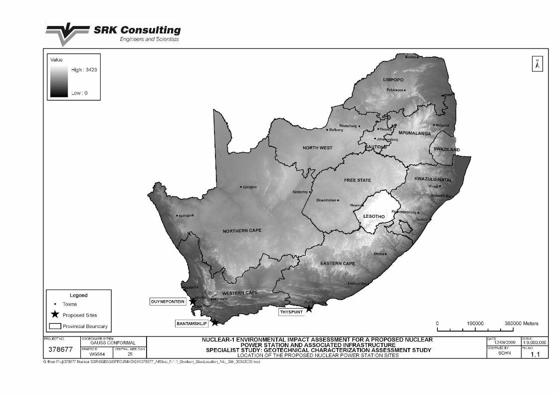
1.1.1 Study Area The three sites mentioned above are located as described in Section 1.2 and are shown on Figure 1.1.
1.2 Study Approach
The environmental impacts on the natural geotechnical environment due to the construction, operation and decommissioning of the plant are limited. The geotechnical character of the sites is, however, an important design driver and certain design features like founding solutions influence proposed layouts and this in turn influences impacts related to a host of other specialist studies (e.g. flora and fauna, hydrogeology etc). It is not common practice to undertake specialist geotechnical impact assessments in EIAs. However, considering the importance of foundations in nuclear power plants, it has been decided that a geotechnical impact assessment be carried out as an additional activity to underpin the EIA as a whole. The environmental impacts on, for example flora, fauna, groundwater flow regimes etc. are not considered in this report, but are dealt with in detail in those specific specialist reports. This geotechnical specialist report therefore aims to: • Define a general geotechnical profile of the sites; and • Describe the construction, operational and decommissioning implications that the
project will have in the context of the site geotechnical profile. The study approach was therefore to: • Gather information from desk top sources that could assist in defining site
geotechnical profiles; • Supplement the desk top information with field intrusive geotechnical investigations;
and • Confirm selected geotechnical parameters with laboratory testing such that the
geotechnical profiles could be finalised.
Nuclear-1 EIA Specialist Study for EIR Geotechnical Characterisation Assessment Study 3 Final / March 2011
Figure 1.1: Location of the Proposed Nuclear Power Station Sites
Nuclear-1 EIA Specialist Study for EIR Geotechnical Characterisation Assessment Study 4 Final / March 2011
1.2.1 Assumptions and Limitations The data used in assessing the geotechnical engineering impacts of a proposed NPS at the sites relies on desk top review and field investigation studies to describe the affected environment. Of particular significance in this project is the fact that geotechnical detail will only become available once the project footprint has been fixed and targeted intrusive investigations are carried out at that location. The reason for this is that intrusive investigations are costly and time consuming and targeted investigations are necessary. Investigations to date have therefore aimed at drafting a geotechnical profile rather than looking at specific geotechnical parameters in fixed areas. A factor to bear in mind is therefore that intrusive geotechnical investigations carried out to date provide only sufficient information to define the general site geotechnical profiles and do not provide sufficient geotechnical design parameter information to comment on the geotechnical issues surrounding specific project components (e.g. the nuclear island). This is not necessarily a limitation in the context of an EIA, however, and the information used in this EIA is considered adequate to make informed conclusions and recommendations.
1.3 Legislative Framework
The legislative framework that covers the licensing and construction of a nuclear power station includes the following: • The National Nuclear Regulator Act, 1999 (NNRA) (Act No. 47 of 1999); • The National Environmental Management Act, 1998 (NEMA), (Act No. 107 of
1998); and • The EIA regulations of 2006 (Government Notice No’s R 385, 386 & 387 of 2006)
promulgated in terms of NEMA The NNRA and NEMA place emphasis on responsible geotechnical characterisation of potential nuclear sites, notwithstanding the need to develop such sites in an environmentally acceptable manner. The objectives of the NNRA are to exercise regulatory control over most aspects of nuclear installations to safeguard persons, property and the environment from nuclear damage. The siting of nuclear installations is an important phase in their development, a phase in which issues influencing the safety of people, property and the environment begin to emerge. Geotechnical characterisation forms a key technical driver for siting of nuclear installations. For this reason, the EIA should take cognisance of the geotechnical character of the sites and the impact that this has on site suitability and siting. The key regulatory motivation for carrying out a specialist geotechnical characterisation study for the EIA is therefore to satisfy the NNRA objectives relating to safety.
Nuclear-1 EIA Specialist Study for EIR Geotechnical Characterisation Assessment Study 5 Final / March 2011
1.4 Information Sources
Various information sources informed the desk top study that initiated the site geotechnical profile description. These include: • Reports describing field investigations that were carried out by the Atomic Energy
Corporation (AEC) in the 1980s as part of a candidate site selection process on all of the three sites mentioned in Section 1.1 and relative to this study.
• Extensive documentation in the vicinity of the Duynefontein site as that site abuts the existing Koeberg Nuclear Power Station (KNPS). A list of references sourced for this study is given in Section 7 . The main sources are the Eskom NSIP reports and the Koeberg Site Safety Report (KSSR).
1.5 Integration with other Studies
The geotechnical characterisation of the sites has both gained from other studies and provided information to other studies. Of particular significance has been the integration with the following disciplines: • Geohydrology: where the groundwater profile measured in the hydrogeological
investigations and in the geotechnical investigations on the sites has been shared and incorporated into dewatering model scenarios and the geotechnical profiles that have developed for the sites; and
• Freshwater ecology: where the influence of groundwater recharge on wetlands, in particular, is informed by the groundwater profile measured in the geotechnical investigation (above bullet).
Nuclear-1 EIA Specialist Study for EIR Geotechnical Characterisation Assessment Study 6 Final / March 2011
2 DESCRIPTION OF AFFECTED ENVIRONMENT
This Section aims at defining the geotechnical profiles at the sites, giving a clear indication of the general nature of the materials underlying the sites.
2.1 Thyspunt Site
2.1.1 Location and General Description
The Thyspunt site is located on the Eastern Cape coast approximately 15 km due west of Cape St. Francis and east of Oyster Bay and Tony’s Bay. The site is fronted by a ragged beachfront, a transitional zone and a double bench dune system consisting of a lower terrace to a height of about 20 mamsl and an upper terrace up to 50 mamsl. The dune system strikes East-North-East and the area is densely vegetated.
2.1.2 Geology Site geology is covered in detail in a separate specialist study and this description is to assist the reader in conceptualising the geotechnical setting only. For detail on the Thyspunt site geology refer to the relevant specialist study. The geology of the site and environs is characterised by east-west trending steeply folded and faulted Cape Supergroup sediments and coastal embayments filled with Cretaceous sediments.
Table 2.1: Regional Geology at Thyspunt
Geological Unit
Material Type Approximate Age Comments
Dune Sand
Calcarenite Bredasdorp Group
Pebbles and Boulders
Cenozoic Age – Tertiary to Quaternary
Unconformably lying on the Peninsula Formation
Peninsula Formation of the Table Mountain Group
Quartzites
The Table Mountain Group is of Ordovician to Silurian Age. The Peninsula Formation within the group is of Ordovician Age.
Unconformably lying on the Cape Granite Suite or Malmesbury Group
Sandstones, siltstones and shales of the Table Mountain and Bokkeveld Groups underlie the area and have been folded and faulted due to the movement and thrusting associated with the breakup of Gondwanaland, which is responsible for the formation of half-grabens (small “rift valleys”) that subsequently filled with Cretaceous sediments eroded from the adjacent mountains. The westward movement of the Falkland Plate along the Agulhas-Falkland Fracture Zone has resulted in a drag-induced curvature to the eastern ends of the faults and folds that is particularly characteristic of the Eastern Cape. Thyspunt is dominated by quartzitic and
Nuclear-1 EIA Specialist Study for EIR Geotechnical Characterisation Assessment Study 7 Final / March 2011
carbonaceous sandstones that dip 50° south, due to the location of the site on the southern limb of a major anticline. The sandstone is overlain by cobble and pebble beds, which are in turn overlain by stabilised sand dunes. The regional geology can be summarised as shown in Table 2.1 .
2.1.3 Regional Geohydrology Site geohydrology is covered in detail in a separate specialist study and this description is to assist the reader in conceptualising the geotechnical setting only. For detail on the Thyspunt site geology refer to the relevant specialist study. Two types of aquifers occur under the Thyspunt site: • A minor fractured rock aquifer (secondary) within the Bokkeveld (predominantly
argillaceous rocks) and TMG (mainly arenaceous) rocks, with some areas of Major Aquifer classification in the latter; and
• A major intergranular aquifer (primary) within variably consolidated deposits of the Nanaga Formation and recent dune sediments (undifferentiated coastal and inland deposits).
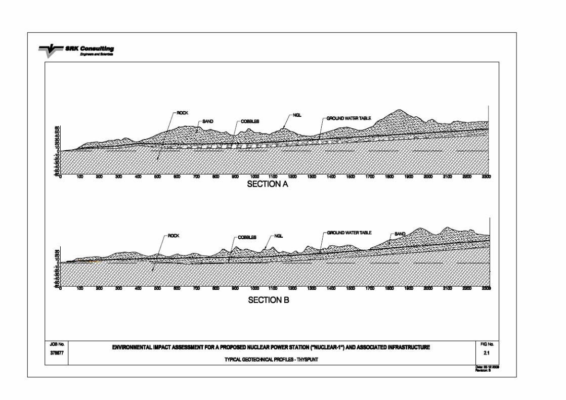
Figure 2.1 shows that the groundwater table daylights at the sea (i.e. is practically at surface and feeds several coastal seeps), but then there is a variance in depth to the groundwater table once in the dune area. Here, the depth to groundwater varies from a few metres under dune troughs to in excess of 40 m under dune peaks.
2.1.4 Seismology Site seismology is covered in detail in a separate specialist study and this description is to assist the reader in conceptualising the geotechnical setting only. For detail on the Thyspunt site seismology refer to the relevant specialist study. The available onshore geological information does not suggest the presence of any significant faults within an 8 km radius of the site. The geological maps depict the area as relatively fault-free. However, numerous offshore faults occur, the largest being the Plettenberg Fault (18 km from the site). A second fault, the Cape St Francis fault is known to exist 16 km from the site and if postulated along strike, could pass just north of the site. The Gamtoos and Kouga Faults occur 45 km from the site and are linked to the 715 km long Ceres-Kango-Baviaanskloof-Coega-St Croix fault system which has been previously associated with seismic events. The potential activity of these faults will be investigated in detail in the seismic specialist studies being undertaken for this project. These studies will be completed over a period of approximately three years.
2.1.5 Liquefaction Potential Soil liquefaction describes the behaviour of loose, saturated unconsolidated soils, i.e. loose sands, which go from a solid state to having the consistency of a heavy liquid (or reach a liquefied state as a consequence of increasing pore water pressures), and thus decreasing effective stress, induced by their tendency to decrease in volume when subjected to cyclic undrained loading (e.g. earthquake loading). Not all soils are susceptible to liquefaction and consequently the first step in a liquefaction analysis is to evaluate the liquefaction potential of the soil. Several criteria are used to evaluate the preliminary liquefaction potential such as:
Nuclear-1 EIA Specialist Study for EIR Geotechnical Characterisation Assessment Study 8 Final / March 2011
• Historic criteria: Liquefaction case histories can be used to identify specific sites
or more general site conditions that are susceptible to liquefaction in future earthquakes.
• Geological Criteria: The depositional and hydrological environments and age of soil deposits contribute to their liquefaction potential. Geological processes that sort soils into uniform size distributions and deposit them in loose states produce soil deposits with a high liquefaction potential. Generally, if soils are deposited in fluvial and/or alluvial, colluvial, aeolian or hydraulic environments, they have a higher tendency to liquefy.
• Compositional criteria: Liquefaction is influenced by compositional characteristics that influence volume change behaviour such as particle size, shape and gradation. Liquefaction is usually associated with sands or silts. Rounded soil particles of uniform size are generally most susceptible to liquefaction while well-graded sands with angular shapes are less prone to liquefy due to interlocking of the grains. Non-plastic fines with a dry surface texture do not create adhesion and do not provide significant resistance to particle re-arrangement and liquefaction. The following criteria may be used as a rule of thumb to identify soils with liquefaction potential:
Percentage finer than 0.005mm ≤ 15% Liquid limit (LL) ≤ 35% Natural water content ≥ 0.9LL Liquidity index ≤ 0.75 Sandy and silty soils of low plasticity and density Soils subjected to saturated conditions Having measured SPT N values < 15
• Permeability influences the liquefaction characteristics of the soil as it governs the flow of pore water in a soil. Soils with a low permeability are more likely to liquefy. Consequently soil with large non-plastic fines content may be more susceptible to liquefaction as the fines inhibit drainage.
In addition to the above material property parameters that influence liquefaction potential, there are other parameters that also come into play. These are: • Plant geometry and finished/design levels:
− the level at which founding is anticipated for this project is at bedrock level, therefore negating the need for liquefaction potential assessments related to soils underneath proposed foundations of safety-related structures;
− the finished level of the NPS, if above the groundwater table, negates the need to assess liquefaction potential in slope soils – the converse is true.
• Seismic response:
− The potential for soils to liquefy is largely influenced by the extent of ground shaking that the site can undergo;
− Sites susceptible to high peak ground accelerations due to earthquakes are more susceptible to liquefaction.
The Thyspunt site soils are non-plastic and are variably consolidated (meaning that there are zones of low density) – this within the groundwater regime described in Section 2.1.3 . Testing (field and laboratory) carried out on soil samples at Thyspunt
Nuclear-1 EIA Specialist Study for EIR Geotechnical Characterisation Assessment Study 9 Final / March 2011
indicate that in some areas, soils with characteristics historically linked to liquefaction are found. A relevant example is that low SPT N (<15) values have been recorded in soils below the water table. There does, therefore, exist a liquefaction potential where low density soils are saturated. However, investigations have determined that there is a general increase in consistency with depth. It is at these greater depths where the groundwater table is always present. Since soils need to be of loose consistency and be saturated in order to liquefy, it would appear that the Thyspunt site soils probably present a low liquefaction potential. High levels of ground shaking, however, could induce liquefaction behaviour in soils at the site. Levels of shaking that the site could be subjected to will be confirmed at a later stage in the project.
2.1.6 Geotechnical Characterisation The geotechnical characterisation of the site is best represented by a geotechnical profile (or cross section). A geotechnical model, based on desk top and intrusive field investigations has evolved for the Thyspunt site. Typical geotechnical profiles for the site are shown in Figure 2.1, which represents cross sections of the site perpendicular to the coastline. It is important to note the following fromFigure 2.1: • The varying overlying soil profile thickness; • The underlying bedrock profile; and • The groundwater table profile relative to the soil and bedrock. a) Site Soils The site soil profile (as shown in Figure 2.1 ) varies considerably in thickness as one moves inland, ranging from 0 m thick (at the sea) to almost 60 m thick within the dune area. The geotechnical properties of the dune sand are consistent across the site and generally can be described as poorly sorted, fine sand with the following grading characteristics: • Clay: 4% • Silt: 3% • Sand: 93% • Gravel: 1% The sand fraction is dominated by fine sand passing the 0.3 mm sieve.
Nuclear-1 EIA Specialist Study for EIR Geotechnical Characterisation Assessment Study 10 Final / March 2011
Figure 2.1: Typical Geotechnical Profiles – Thyspun t
Nuclear-1 EIA Specialist Study for EIR Geotechnical Characterisation Assessment Study 11 Final / March 2011
The fines portion of the sand (clay and silt) exhibits low to no plasticity. The variable consistency of the site soils is a notable feature. The soils at Thyspunt are typical of coastal dune environments and with low density soils having no plasticity, these soils are highly susceptible to wind erosion. This stands to reason as the dune systems, although stabilised with vegetation currently, were in all likelihood historically roaming systems, their mobility reliant on wind-blown sands. The lack of fines (clay and silt) material within the soils indicates that these soils have no cohesion. Excavations within these soils will therefore require either lateral support (where this is practical – e.g. when excavations are less than say 20 m deep and no groundwater is present) or they will have to be battered back to safe angles (in the region of 20º) when groundwater is present. Long term integrity of excavations in this material can also only be attained if the cut slopes are dewatered. Dewatering is therefore a definite requirement in stabilisation of excavations that probe founding depths on (or in) bedrock.
b) Rocks
The rock terrace underlying the soil overburden at Thyspunt is a wave cut platform, previously subjected to erosion by the sea. The bedrock level is at (or just above) mean sea level from the sea to approximately 1 km inland. There then appears to be a gradual rise in bedrock level to approximately 60 mamsl about 2.5 km inland. The rock terrace is therefore consistently at (or just above) mean sea level within the project focus area. An exception is within a zone from approximately 500 m to 1 000 m from the sea where quartzitic sandstones of the Goudini Formation occur. These sandstones are more susceptible to erosion. Wave action eroded a depression in the bedrock within the Goudini rocks and a deposit of cobbles, boulders and pebbles has been left within the depression. Thysbaai was, in all likelihood, formed within Goudini rocks as the sea eroded the bay out of this more erodible material. The presence of this Goudini depression is an important feature in the site geotechnical profile for the following reasons:
• The cobbles, boulders and pebbles create a preferential groundwater seepage zone, locally influencing groundwater flow direction from perpendicular to the coast/southwards (the regional flow direction) to south eastwards as groundwater is ‘sucked’ down the depression;
• The presence of the depression confirms a softer geotechnical zone – more erodible quartzitic sandstone of the Goudini Formation, bound on the northern and southern extents by less erodible quartzitic sandstone of the Peninsula and Skurweberg Formations respectively.
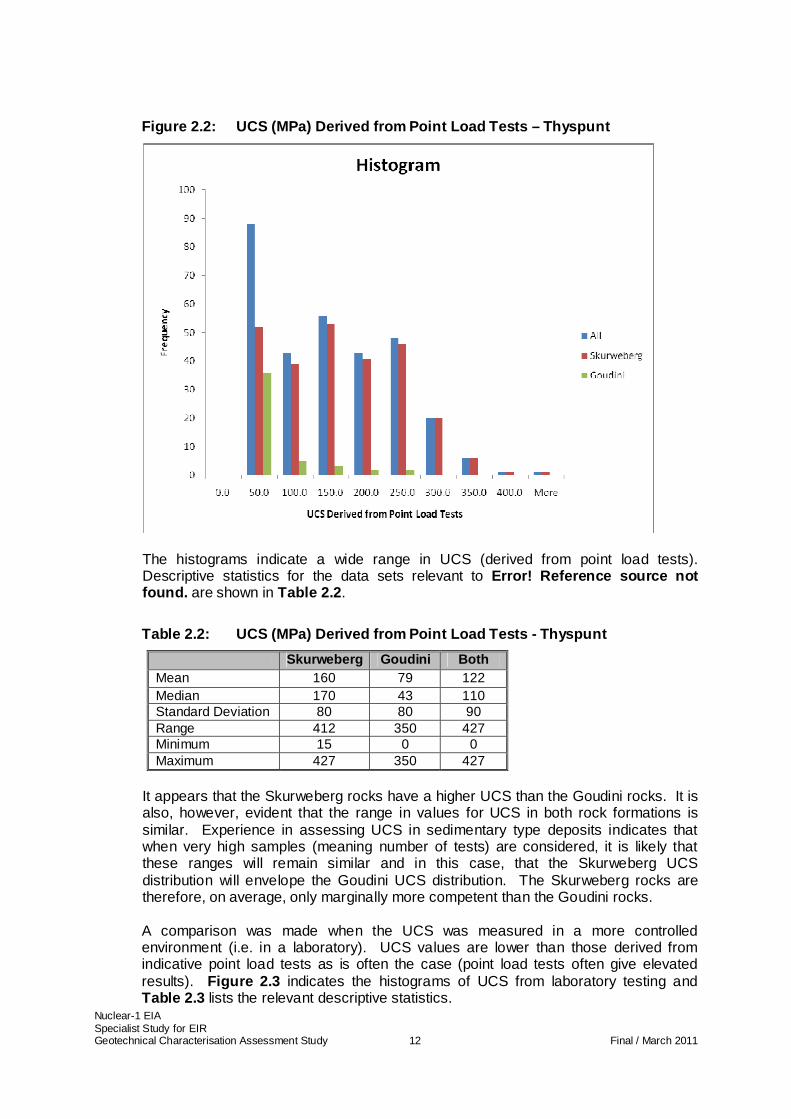
Point load field tests were carried out on borehole core extracted from the Skurweberg and Goudini geological formations. Point load tests are done to give an indication of the likely rock strength in that the uniaxial compressive strength (UCS) of the rock can be derived from the point load test results. Figure 2.2 shows a histogram of the UCS derived from point load testing.
Nuclear-1 EIA Specialist Study for EIR Geotechnical Characterisation Assessment Study 12 Final / March 2011
Figure 2.2: UCS (MPa) Derived from Point Load Tests – Thyspunt
The histograms indicate a wide range in UCS (derived from point load tests). Descriptive statistics for the data sets relevant to Error! Reference source not found. are shown in Table 2.2 .
Table 2.2: UCS (MPa) Derived from Point Load Tests - Thyspunt
Skurweberg Goudini Both Mean 160 79 122 Median 170 43 110 Standard Deviation 80 80 90 Range 412 350 427 Minimum 15 0 0 Maximum 427 350 427
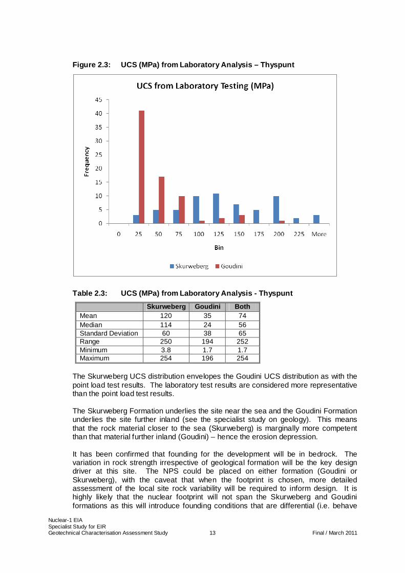
It appears that the Skurweberg rocks have a higher UCS than the Goudini rocks. It is also, however, evident that the range in values for UCS in both rock formations is similar. Experience in assessing UCS in sedimentary type deposits indicates that when very high samples (meaning number of tests) are considered, it is likely that these ranges will remain similar and in this case, that the Skurweberg UCS distribution will envelope the Goudini UCS distribution. The Skurweberg rocks are therefore, on average, only marginally more competent than the Goudini rocks. A comparison was made when the UCS was measured in a more controlled environment (i.e. in a laboratory). UCS values are lower than those derived from indicative point load tests as is often the case (point load tests often give elevated results). Figure 2.3 indicates the histograms of UCS from laboratory testing and Table 2.3 lists the relevant descriptive statistics.
Nuclear-1 EIA Specialist Study for EIR Geotechnical Characterisation Assessment Study 13 Final / March 2011
Figure 2.3: UCS (MPa) from Laboratory Analysis – Th yspunt
Table 2.3: UCS (MPa) from Laboratory Analysis - Thy spunt
Skurweberg Goudini Both Mean 120 35 74 Median 114 24 56 Standard Deviation 60 38 65 Range 250 194 252 Minimum 3.8 1.7 1.7 Maximum 254 196 254
The Skurweberg UCS distribution envelopes the Goudini UCS distribution as with the point load test results. The laboratory test results are considered more representative than the point load test results. The Skurweberg Formation underlies the site near the sea and the Goudini Formation underlies the site further inland (see the specialist study on geology). This means that the rock material closer to the sea (Skurweberg) is marginally more competent than that material further inland (Goudini) – hence the erosion depression. It has been confirmed that founding for the development will be in bedrock. The variation in rock strength irrespective of geological formation will be the key design driver at this site. The NPS could be placed on either formation (Goudini or Skurweberg), with the caveat that when the footprint is chosen, more detailed assessment of the local site rock variability will be required to inform design. It is highly likely that the nuclear footprint will not span the Skurweberg and Goudini formations as this will introduce founding conditions that are differential (i.e. behave

Nuclear-1 EIA Specialist Study for EIR Geotechnical Characterisation Assessment Study 14 Final / March 2011
differently under imposed loading). From a geotechnical engineering perspective, this is to be avoided.
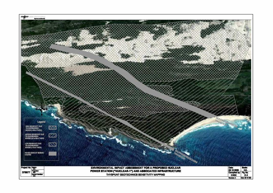
2.1.7 Evaluation of site sensitivity Based on the above, the Thyspunt site has been assessed relative to the site sensitivity from a geotechnical characterisation viewpoint. An obvious driver is the depth of overburden sand that will be removed in order to reach bedrock for founding of the NPS. The overburden has been characterised as non-cohesive material (i.e. sand as opposed to cohesive material like clay). This means that significant excavations will need to be cut back to acceptable angles to ensure safety during construction. For the purposes of defining site sensitivity, the following criteria have been used: • LOW sensitivity is described as those areas where overburden sand is less than
10 m in vertical extent; • MEDIUM sensitivity is described as those areas where overburden sand is between
10 and 20 m in vertical extent; and • HIGH sensitivity is described by those areas where overburden sand is greater than
20 m in vertical extent.
Figure 2.4 shows these areas diagrammatically.
Nuclear-1 EIA Specialist Study for EIR Geotechnical Characterisation Assessment Study 15 Final / March 2011
Figure 2.4: Thyspunt Geotechnics Sensitivity Mapping
Nuclear-1 EIA Specialist Study for EIR Geotechnical Characterisation Assessment Study 16 Final / March 2011
2.2 Bantamsklip Site
2.2.1 Location and General Description
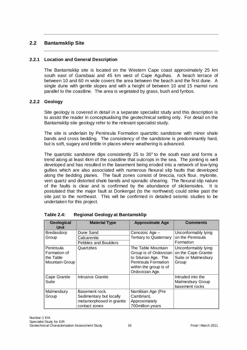
The Bantamsklip site is located on the Western Cape coast approximately 25 km south east of Gansbaai and 45 km west of Cape Agulhas. A beach terrace of between 10 and 60 m wide covers the area between the beach and the first dune. A single dune with gentle slopes and with a height of between 10 and 15 mamsl runs parallel to the coastline. The area is vegetated by grass, bush and fynbos.
2.2.2 Geology Site geology is covered in detail in a separate specialist study and this description is to assist the reader in conceptualising the geotechnical setting only. For detail on the Bantamsklip site geology refer to the relevant specialist study. The site is underlain by Peninsula Formation quartzitic sandstone with minor shale bands and cross bedding. The consistency of the sandstone is predominantly hard, but is soft, sugary and brittle in places where weathering is advanced. The quartzitic sandstone dips consistently 25 to 30° to the south east and forms a trend along at least 4km of the coastline that outcrops in the sea. The jointing is well developed and has resulted in the basement being eroded into a network of low-lying gullies which are also associated with numerous flexural slip faults that developed along the bedding planes. The fault zones consist of breccia, rock flour, mylonite, vein quartz and distorted shale bands and sporadic shearing. The flexural slip nature of the faults is clear and is confirmed by the abundance of slickensides. It is postulated that the major fault at Donkergat (to the northwest) could strike past the site just to the northeast. This will be confirmed in detailed seismic studies to be undertaken for this project.
Table 2.4: Regional Geology at Bantamsklip
Geological Unit
Material Type Approximate Age Comments
Dune Sand Calcarenite
Bredasdorp Group
Pebbles and Boulders
Cenozoic Age – Tertiary to Quaternary
Unconformably lying on the Peninsula Formation
Peninsula Formation of the Table Mountain Group
Quartzites The Table Mountain Group is of Ordovician to Silurian Age. The Peninsula Formation within the group is of Ordovician Age.
Unconformably lying on the Cape Granite Suite or Malmesbury Group
Cape Granite Suite
Intrusive Granite Intruded into the Malmesbury Group basement rocks
Malmesbury Group
Basement rock. Sedimentary but locally metamorphosed in granite contact zones
Namibian Age (Pre Cambrian). Approximately 700million years
Nuclear-1 EIA Specialist Study for EIR Geotechnical Characterisation Assessment Study 17 Final / March 2011
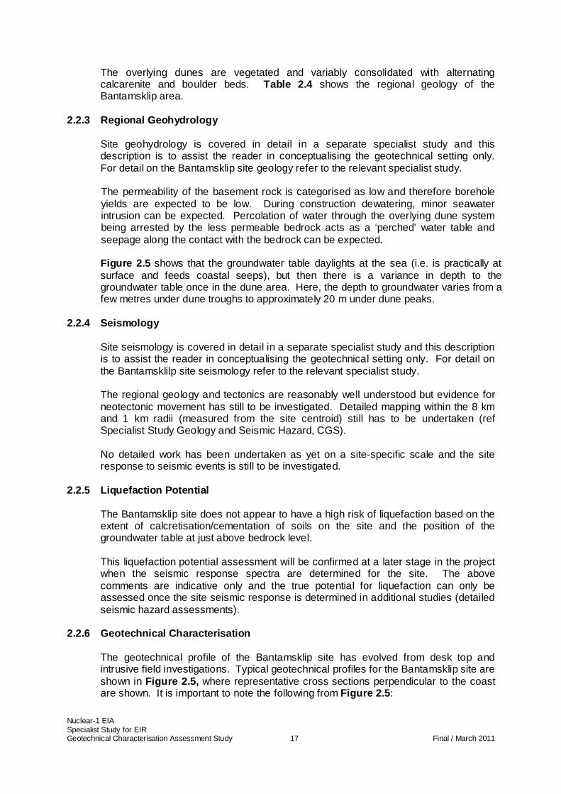
The overlying dunes are vegetated and variably consolidated with alternating calcarenite and boulder beds. Table 2.4 shows the regional geology of the Bantamsklip area.
2.2.3 Regional Geohydrology Site geohydrology is covered in detail in a separate specialist study and this description is to assist the reader in conceptualising the geotechnical setting only. For detail on the Bantamsklip site geology refer to the relevant specialist study. The permeability of the basement rock is categorised as low and therefore borehole yields are expected to be low. During construction dewatering, minor seawater intrusion can be expected. Percolation of water through the overlying dune system being arrested by the less permeable bedrock acts as a ‘perched’ water table and seepage along the contact with the bedrock can be expected. Figure 2.5 shows that the groundwater table daylights at the sea (i.e. is practically at surface and feeds coastal seeps), but then there is a variance in depth to the groundwater table once in the dune area. Here, the depth to groundwater varies from a few metres under dune troughs to approximately 20 m under dune peaks.
2.2.4 Seismology Site seismology is covered in detail in a separate specialist study and this description is to assist the reader in conceptualising the geotechnical setting only. For detail on the Bantamsklilp site seismology refer to the relevant specialist study. The regional geology and tectonics are reasonably well understood but evidence for neotectonic movement has still to be investigated. Detailed mapping within the 8 km and 1 km radii (measured from the site centroid) still has to be undertaken (ref Specialist Study Geology and Seismic Hazard, CGS). No detailed work has been undertaken as yet on a site-specific scale and the site response to seismic events is still to be investigated.
2.2.5 Liquefaction Potential The Bantamsklip site does not appear to have a high risk of liquefaction based on the extent of calcretisation/cementation of soils on the site and the position of the groundwater table at just above bedrock level. This liquefaction potential assessment will be confirmed at a later stage in the project when the seismic response spectra are determined for the site. The above comments are indicative only and the true potential for liquefaction can only be assessed once the site seismic response is determined in additional studies (detailed seismic hazard assessments).
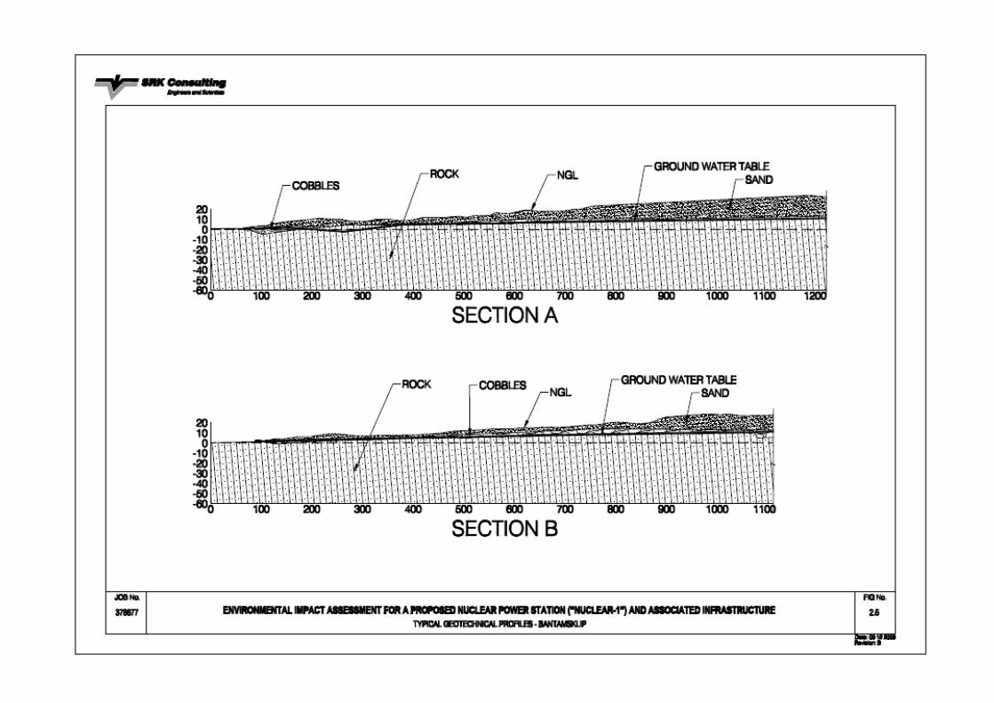
2.2.6 Geotechnical Characterisation The geotechnical profile of the Bantamsklip site has evolved from desk top and intrusive field investigations. Typical geotechnical profiles for the Bantamsklip site are shown in Figure 2.5, where representative cross sections perpendicular to the coast are shown. It is important to note the following from Figure 2.5 :
Nuclear-1 EIA Specialist Study for EIR Geotechnical Characterisation Assessment Study 18 Final / March 2011
• The increase in thickness of the overlying soil profile as one moves inland; • The underlying bedrock profile; and • The groundwater table profile situated just above bedrock.
a) Site soils
The site soil profile (as shown in Figure 2.5 ) varies in thickness as one moves inland, ranging from zero meters thick (at the sea) to less than 20 m thick within the dune area. The geotechnical properties of the dune sand are consistent across the site and generally can be described as poorly sorted, fine sand with the following grading characteristics: • Clay: 5% • Silt: 4% • Sand: 91% • Gravel: 0%
The sand fraction is dominated by fine sand passing the 0,300 to 0,425 mm sieves. The fines portion of the grading (clay and silt) exhibits low to no plasticity. The consistency of the site soils is homogenous at the Bantamsklip site. The soils are typical of coastal dune environments and are highly susceptible to wind erosion in un-cemented horizons. The soils have no cohesion (except where calcrete has formed), and excavations within these soils will therefore require either lateral support or they will have to be battered back to safe angles. There are extensive calcrete zones within the site soils and lateral support on this site will be simplified by this as the calcrete lends cohesion to the sand.
Nuclear-1 EIA Specialist Study for EIR Geotechnical Characterisation Assessment Study 19 Final / March 2011
Figure 2.5: Typical Geotechnical Profiles – Bantamsklip
Nuclear-1 EIA Specialist Study for EIR Geotechnical Characterisation Assessment Study 20 Final / March 2011
b) Rocks
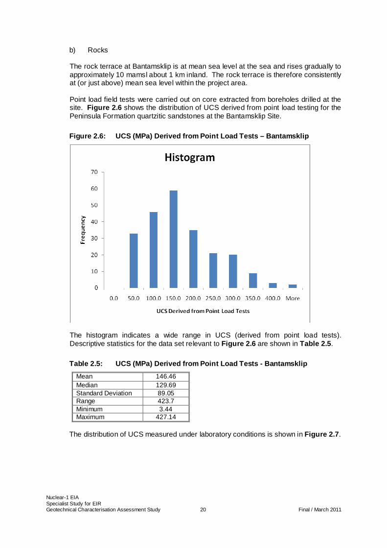
The rock terrace at Bantamsklip is at mean sea level at the sea and rises gradually to approximately 10 mamsl about 1 km inland. The rock terrace is therefore consistently at (or just above) mean sea level within the project area. Point load field tests were carried out on core extracted from boreholes drilled at the site. Figure 2.6 shows the distribution of UCS derived from point load testing for the Peninsula Formation quartzitic sandstones at the Bantamsklip Site.
Figure 2.6: UCS (MPa) Derived from Point Load Tests – Bantamsklip
The histogram indicates a wide range in UCS (derived from point load tests). Descriptive statistics for the data set relevant to Figure 2.6 are shown in Table 2.5 .
Table 2.5: UCS (MPa) Derived from Point Load Tests - Bantamsklip
Mean 146.46 Median 129.69 Standard Deviation 89.05 Range 423.7 Minimum 3.44 Maximum 427.14
The distribution of UCS measured under laboratory conditions is shown in Figure 2.7 .
Nuclear-1 EIA Specialist Study for EIR Geotechnical Characterisation Assessment Study 21 Final / March 2011
Figure 2.7: UCS (MPa) from Laboratory Analysis – Ba ntamsklip
Descriptive statistics for the data sets relevant to Figure 2.7 are shown in Table 2.6 .
Table 2.6: UCS (MPa) from Laboratory Analysis - Ban tamsklip
Mean 120 Median 103 Standard Deviation 85 Range 410 Minimum 21 Maximum 431
The average UCS value obtained in the laboratory is higher than that derived from point load tests, but the standard deviation in results is also higher. These variations in measured rock strength are almost certainly related to the highly jointed/fractured nature of the rocks. It is therefore difficult to make a comparison of these results, except to say that the quartzitic sandstones at this site have high UCS. The rocks at Bantamsklip are extensively jointed due to past tectonic activity. The dominance of major discontinuities (joints) within the rock mass is a key geotechnical characteristic at this site and contributes to some lateral variability in rock strength.
2.2.7 Evaluation of site sensitivity Based on the above, the Bantamsklip site has been assessed relative to the site sensitivity from a geotechnical characterisation viewpoint on the same criteria as Thyspunt.
Figure 2.8 shows these areas diagrammatically.
Nuclear-1 EIA Specialist Study for EIR Geotechnical Characterisation Assessment Study 22 Final / March 2011
Figure 2.8: Bantamsklip Geotechnics Sensitivity Mapping
Nuclear-1 EIA Specialist Study for EIR Geotechnical Characterisation Assessment Study 23 Final / March 2011
2.3 Duynefontein Site
A considerable quantum of work has been done on the existing KNPS and an extensive data base of geological and geotechnical information has been collected over the years. For the purposes of this report, only the salient features will be highlighted within the geotechnical profile.
2.3.1 Location and General Description The Duynefontein site lies approximately 30 km north of Cape Town within the coastal plain of the Western Cape Province, which is covered for the most part by Tertiary to Recent deposits. Ancient dunes, stabilised by vegetation and Recent unconsolidated dunes, occupy large areas. This, referred to as the Sandveld, rises gently towards the east and southeast to an average elevation of between 100 and 200 m some 20 km east of the Koeberg site. The south-eastern margin is demarcated by the Tierberg Formation, whilst the Darling Range dissects the coastal plain in the north and the Blouberg hill forms a prominent feature some 10 km to the south of the site.
2.3.2 Geology Site geology is covered in detail in a separate specialist study and this description is to assist the reader in conceptualising the geotechnical setting only. For detail on the Duynefontein site geology refer to the relevant specialist study. The area is underlain almost entirely by folded rocks of the Malmesbury group. This stratigraphic unit is typified by the Tygerberg Formation, with greywackes, mudstones and intermittent shale bands being the principal rock types in the site area. These rocks are overlain by unconsolidated sands of Tertiary to Recent age. The time gap between the folded Malmesbury and the Tertiary exceeds 500 Ma. In broad terms, the soils that underlie the area consist of a sequence of variably calcareous and fossiliferous aeolian, estuarine and marine sands deposited on a bedrock surface of interbedded greywackes, mudstones and shale bands. This bedrock surface, a wave-cut platform of Tertiary age, lies at approximately -10 mamsl at the coast. The site sands consist of an upper horizon, which is mainly light grey to light brown, generally fine-grained with numerous interbedded medium- and coarse-grained lenses and layers, as well as calcrete which varies in its degree of development from a white dusty colouration to a well cemented bouldery layer, and variable but significant amounts of shell debris. The lower horizon consists of medium-dense to dense, fine to very fine sands with occasional shell fragments containing thin bands of coarse sandy gravel. Table 2.7 describes the regional geology in the Duynefontein area.
Nuclear-1 EIA Specialist Study for EIR Geotechnical Characterisation Assessment Study 24 Final / March 2011
Table 2.7: Regional Geology at Duynefontein.
Age Lithology Formation Group
Sandy soil, poorly sorted and slightly clayey
-
Ho
loce
ne
Aeolian/calcareous quartzose sand Witzand
Aeolian/calcrete-capped calcareous sandstone
Langebaan
Littoral coquina and sandstone Velddrif
Qua
rte
rna
ry
Ple
isto
cene
Aeolian/quartzose sand with intermittent peaty layers
Springfontein
Plio
cene
Quartzose and muddy sand, and shelly gravel, phosphate-rich*
Varswater
Neo
gene
Mio
cen
e
Silcrete Bellville
Sandveld
Jura
ssic
Dolerite Karoo dolerite dykes
Sandstones and shales - Cape Supergroup
Ord
ovic
ian
to
Low
er
Ca
rbo
nife
rou
s
Dolerite Pre-Cape dolerite dykes
Ca
mb
rian
Sandstones and conglomerates Klipheuwel
Granites with hybrid and porphyritic varieties;diorites; augengeisses
- Cape Granite Suite (Darling Batholith)
La
te
Pre
cam
bria
n
Greywacke, sandstone, mudstone and shale; metamorphosed equivalents.*
- Malmesbury
* Known to occur at the local Duynefontein site
The sand layers show a consistent trend in becoming finer-grained with increasing depth. No residual soil materials have been observed.
The term “greywackes” describes a group of rocks consisting of dark-coloured, poorly sorted clayey sandstones or fine grits. Bedrock materials encountered in the boreholes consist, in the unweathered state, of massive, fine- to medium- grained, quartzitic, occasionally cross-bedded, indurated, grey, extremely hard rock greywackes and fine-grained, even textured, moderately hard rock, grey or grey-
Nuclear-1 EIA Specialist Study for EIR Geotechnical Characterisation Assessment Study 25 Final / March 2011
green, bedded mudstones with subordinate micaceous laminated shale bands that are rare in occurrence but usually less than a metre in thickness.
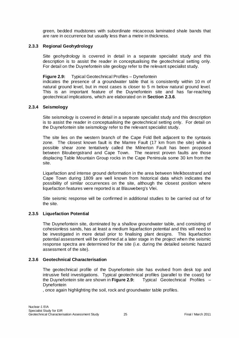
2.3.3 Regional Geohydrology Site geohydrology is covered in detail in a separate specialist study and this description is to assist the reader in conceptualising the geotechnical setting only. For detail on the Duynefontein site geology refer to the relevant specialist study. Figure 2.9: Typical Geotechnical Profiles – Dynefontein indicates the presence of a groundwater table that is consistently within 10 m of natural ground level, but in most cases is closer to 5 m below natural ground level. This is an important feature of the Duynefontein site and has far-reaching geotechnical implications, which are elaborated on in Section 2.3.6 .
2.3.4 Seismology Site seismology is covered in detail in a separate specialist study and this description is to assist the reader in conceptualising the geotechnical setting only. For detail on the Duynefontein site seismology refer to the relevant specialist study. The site lies on the western branch of the Cape Fold Belt adjacent to the syntaxis zone. The closest known fault is the Mamre Fault (17 km from the site) while a possible shear zone tentatively called the Milnerton Fault has been proposed between Bloubergstrand and Cape Town. The nearest proven faults are those displacing Table Mountain Group rocks in the Cape Peninsula some 30 km from the site. Liquefaction and intense ground deformation in the area between Melkbosstrand and Cape Town during 1809 are well known from historical data which indicates the possibility of similar occurrences on the site, although the closest position where liquefaction features were reported is at Blauweberg’s Vlei. Site seismic response will be confirmed in additional studies to be carried out of for the site.
2.3.5 Liquefaction Potential The Duynefontein site, dominated by a shallow groundwater table, and consisting of cohesionless sands, has at least a medium liquefaction potential and this will need to be investigated in more detail prior to finalising plant designs. This liquefaction potential assessment will be confirmed at a later stage in the project when the seismic response spectra are determined for the site (i.e. during the detailed seismic hazard assessment of the site).
2.3.6 Geotechnical Characterisation The geotechnical profile of the Duynefontein site has evolved from desk top and intrusive field investigations. Typical geotechnical profiles (parallel to the coast) for the Duynefontein site are shown in Figure 2.9: Typical Geotechnical Profiles – Dynefontein , once again highlighting the soil, rock and groundwater table profiles.
Nuclear-1 EIA Specialist Study for EIR Geotechnical Characterisation Assessment Study 26 Final / March 2011
Figure 2.9: Typical Geotechnical Profiles – Dynefontein
Nuclear-1 EIA Specialist Study for EIR Geotechnical Characterisation Assessment Study 27 Final / March 2011
a) Site soils
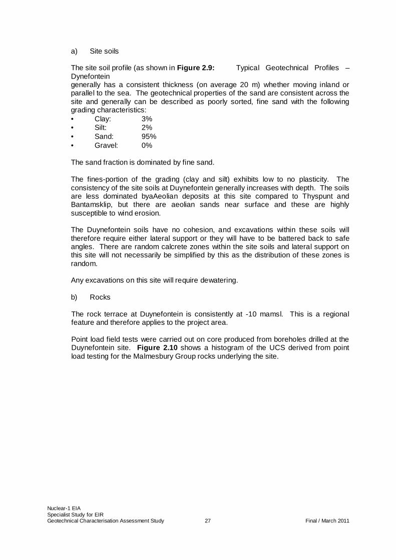
The site soil profile (as shown in Figure 2.9: Typical Geotechnical Profiles – Dynefontein generally has a consistent thickness (on average 20 m) whether moving inland or parallel to the sea. The geotechnical properties of the sand are consistent across the site and generally can be described as poorly sorted, fine sand with the following grading characteristics: • Clay: 3% • Silt: 2% • Sand: 95% • Gravel: 0% The sand fraction is dominated by fine sand. The fines-portion of the grading (clay and silt) exhibits low to no plasticity. The consistency of the site soils at Duynefontein generally increases with depth. The soils are less dominated byaAeolian deposits at this site compared to Thyspunt and Bantamsklip, but there are aeolian sands near surface and these are highly susceptible to wind erosion. The Duynefontein soils have no cohesion, and excavations within these soils will therefore require either lateral support or they will have to be battered back to safe angles. There are random calcrete zones within the site soils and lateral support on this site will not necessarily be simplified by this as the distribution of these zones is random. Any excavations on this site will require dewatering.
b) Rocks
The rock terrace at Duynefontein is consistently at -10 mamsl. This is a regional feature and therefore applies to the project area. Point load field tests were carried out on core produced from boreholes drilled at the Duynefontein site. Figure 2.10 shows a histogram of the UCS derived from point load testing for the Malmesbury Group rocks underlying the site.
Nuclear-1 EIA Specialist Study for EIR Geotechnical Characterisation Assessment Study 28 Final / March 2011
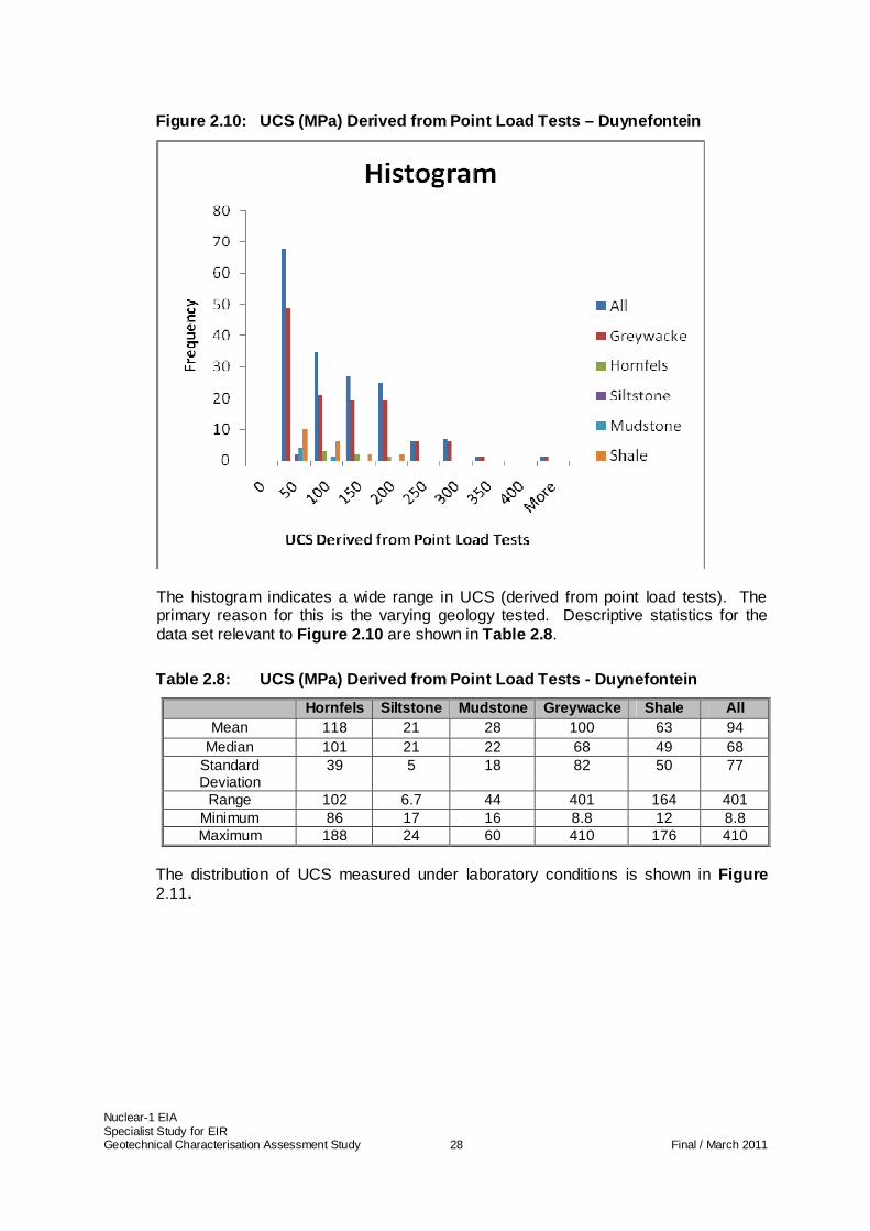
Figure 2.10: UCS (MPa) Derived from Point Load Test s – Duynefontein
The histogram indicates a wide range in UCS (derived from point load tests). The primary reason for this is the varying geology tested. Descriptive statistics for the data set relevant to Figure 2.10 are shown in Table 2.8 .
Table 2.8: UCS (MPa) Derived from Point Load Tests - Duynefontein
Hornfels Siltstone Mudstone Greywacke Shale All Mean 118 21 28 100 63 94
Median 101 21 22 68 49 68 Standard Deviation
39 5 18 82 50 77
Range 102 6.7 44 401 164 401 Minimum 86 17 16 8.8 12 8.8 Maximum 188 24 60 410 176 410
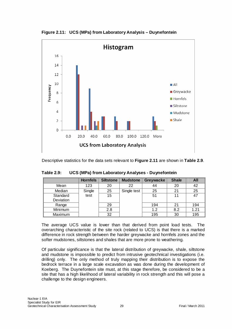
The distribution of UCS measured under laboratory conditions is shown in Figure 2.11.
Nuclear-1 EIA Specialist Study for EIR Geotechnical Characterisation Assessment Study 29 Final / March 2011
Figure 2.11: UCS (MPa) from Laboratory Analysis – D uynefontein
Descriptive statistics for the data sets relevant to Figure 2.11 are shown in Table 2.9 .
Table 2.9: UCS (MPa) from Laboratory Analyses - Duy nefontein
Hornfels Siltstone Mudstone Greywacke Shale All Mean 123 20 22 44 20 42
Median 25 25 21 25 Standard Deviation
15 51 11 47
Range 29 194 21 194 Minimum 2.8 1.2 8.2 1.21 Maximum
Single test
32
Single test
195 30 195 The average UCS value is lower than that derived from point load tests. The overarching characteristic of the site rock (related to UCS) is that there is a marked difference in rock strength between the harder greywacke and hornfels zones and the softer mudstones, siltstones and shales that are more prone to weathering. Of particular significance is that the lateral distribution of greywacke, shale, siltstone and mudstone is impossible to predict from intrusive geotechnical investigations (i.e. drilling) only. The only method of truly mapping their distribution is to expose the bedrock terrace in a large scale excavation as was done during the development of Koeberg. The Duynefontein site must, at this stage therefore, be considered to be a site that has a high likelihood of lateral variability in rock strength and this will pose a challenge to the design engineers.
Nuclear-1 EIA Specialist Study for EIR Geotechnical Characterisation Assessment Study 30 Final / March 2011
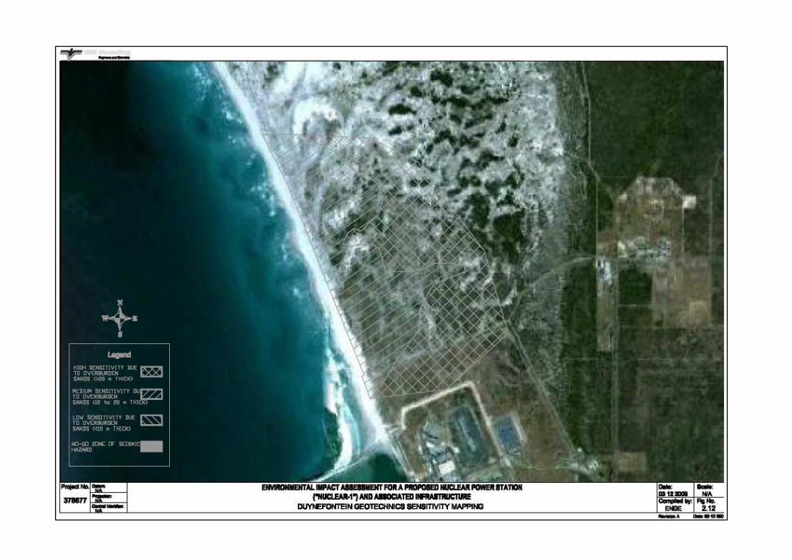
2.3.7 Evaluation of site sensitivity Based on the above, the Duynefontein site has been assessed relative to the site sensitivity from a geotechnical characterisation viewpoint on the same criteria as Thyspunt.
Figure 2.12 shows these areas diagrammatically.
Nuclear-1 EIA Specialist Study for EIR Geotechnical Characterisation Assessment Study 31 Final / March 2011
Figure 2.12: Duynefontein Geotechnics Sensitivity Mapping
Nuclear-1 EIA Specialist Study for EIR Geotechnical Characterisation Assessment Study 32 Final / March 2011
3 IMPACT IDENTIFICATION AND ASSESSMENT
Several important geotechnical issues can be highlighted that potentially position the site geotechnical characterisation as a key focus in the project design. However, very few of these critical design drivers result in any significant direct environmental impacts on the natural geotechnical environment.
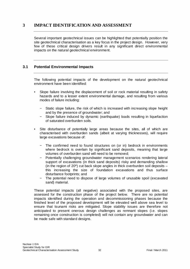
3.1 Potential Environmental Impacts
The following potential impacts of the development on the natural geotechnical environment have been identified: • Slope failure involving the displacement of soil or rock material resulting in safety
hazards and to a lesser extent environmental damage, and resulting from various modes of failure including:
− Static slope failure, the risk of which is increased with increasing slope height
and by the presence of groundwater; and − Slope failure induced by dynamic (earthquake) loads resulting in liquefaction
of saturated overburden soils.
• Site disturbance of potentially large areas because the sites, all of which are characterised with overburden sands (albeit at varying thicknesses), will require large excavations because of: − The confirmed need to found structures on (or in) bedrock in environments
where bedrock is overlain by significant sand deposits, meaning that large volumes of overburden sand will need to be removed;
− Potentially challenging groundwater management scenarios rendering lateral support of excavations (in thick sand deposits) risky and demanding shallow (in the region of 20º) cut back slope angles in thick overburden soil deposits – this increasing the size of foundation excavations and thus surface disturbance footprints; and
− The potential need to dispose of large volumes of unusable spoil (excavated sand) material.
These potential impacts (all negative) associated with the proposed sites, are assessed for the construction phase of the project below. There are no potential impacts identified during the operation and decommissioning phases because the finished level of the proposed development will be elevated well above sea level to ensure that tsunami risks are mitigated. Slope stability issues are therefore not anticipated to present onerous design challenges as remnant slopes (i.e. slopes remaining once construction is completed) will not contain any groundwater and can be made safe with standard designs.
Nuclear-1 EIA Specialist Study for EIR Geotechnical Characterisation Assessment Study 33 Final / March 2011
3.2 Geographical Significance
The thickness of overburden sands and the presence of groundwater influence the extent of the above impacts. The proposed nuclear island will be founded in bedrock and an increase in overburden thickness (or depth to bedrock) requires larger (and deeper) excavations, the design of which is more challenging with the presence of groundwater. This section defines, on a site specific scale, how the impacts are spatially influenced at each of the sites.
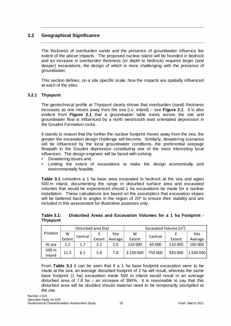
3.2.1 Thyspunt The geotechnical profile at Thyspunt clearly shows that overburden (sand) thickness increases as one moves away from the sea (i.e. inland) – see Figure 2.1 . It is also evident from Figure 2.1 that a groundwater table exists across the site and groundwater flow is influenced by a north west/south east orientated depression in the Goudini Formation rocks. It stands to reason that the further the nuclear footprint moves away from the sea, the greater the excavation design challenge will become. Similarly, dewatering scenarios will be influenced by the local groundwater conditions, the preferential seepage flowpath in the Goudini depression constituting one of the more interesting local influences. The design engineer will be faced with solving: • Dewatering issues and; • Limiting the extent of excavations to make the design economically and
environmentally feasible. Table 3.1 considers a 1 ha base area excavated to bedrock at the sea and again 500 m inland, documenting the range in disturbed surface area and excavated volumes that would be experienced should 1 ha excavations be made for a nuclear installation. These calculations are based on the assumption that excavation slopes will be battered back to angles in the region of 20º to ensure their stability and are included in this assessment for illustrative purposes only.
Table 3.1: Disturbed Areas and Excavation Volumes f or a 1 ha Footprint - Thyspunt
Disturbed area (ha) Excavated Volume (m3)
Position W
Extent Central
E
Extent Site
Average W
Extent Central
E
Extent Site
Average At sea 2.2 1.7 2.1 2.0 120 000 60 000 110 000 100 000 500 m
Inland 11.3 6.1 5.8 7.8 3 230 000 750 000 920 000 1 630 000
From Table 3.1 it can be seen that if a 1 ha base footprint excavation were to be made at the sea, an average disturbed footprint of 2 ha will result, whereas the same base footprint (1 ha) excavation made 500 m inland would result in an average disturbed area of 7.8 ha – an increase of 390%. It is reasonable to say that this disturbed area will be doubled should material need to be temporarily stockpiled at the site.
Nuclear-1 EIA Specialist Study for EIR Geotechnical Characterisation Assessment Study 34 Final / March 2011
Similarly, excavated volumes increase in the 500 m inland excavation, on average from 100 000 m3 to 1 630 000 m3, an increase of 1 700%. The marked difference in excavated volumes and resulting disturbed area are highlighted between the sea and 500 m inland, however, there is also an increase in the western extent of the site where the sand dunes are highest. This is particularly evident in the excavation volumes, where there is an estimated increase of some 2 600% between the sea and 500 m inland between the eastern and western extent of the site.
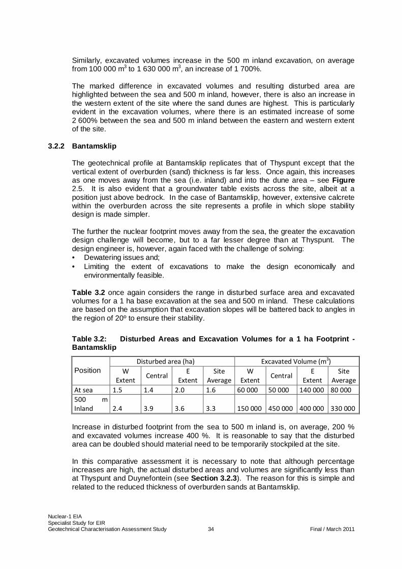
3.2.2 Bantamsklip The geotechnical profile at Bantamsklip replicates that of Thyspunt except that the vertical extent of overburden (sand) thickness is far less. Once again, this increases as one moves away from the sea (i.e. inland) and into the dune area – see Figure 2.5. It is also evident that a groundwater table exists across the site, albeit at a position just above bedrock. In the case of Bantamsklip, however, extensive calcrete within the overburden across the site represents a profile in which slope stability design is made simpler. The further the nuclear footprint moves away from the sea, the greater the excavation design challenge will become, but to a far lesser degree than at Thyspunt. The design engineer is, however, again faced with the challenge of solving: • Dewatering issues and; • Limiting the extent of excavations to make the design economically and
environmentally feasible. Table 3.2 once again considers the range in disturbed surface area and excavated volumes for a 1 ha base excavation at the sea and 500 m inland. These calculations are based on the assumption that excavation slopes will be battered back to angles in the region of 20º to ensure their stability.
Table 3.2: Disturbed Areas and Excavation Volumes f or a 1 ha Footprint - Bantamsklip
Disturbed area (ha) Excavated Volume (m3) Position W
Extent Central
E
Extent
Site
Average
W
Extent Central
E
Extent
Site
Average
At sea 1.5 1.4 2.0 1.6 60 000 50 000 140 000 80 000
500 m
Inland 2.4 3.9 3.6 3.3 150 000 450 000 400 000 330 000
Increase in disturbed footprint from the sea to 500 m inland is, on average, 200 % and excavated volumes increase 400 %. It is reasonable to say that the disturbed area can be doubled should material need to be temporarily stockpiled at the site. In this comparative assessment it is necessary to note that although percentage increases are high, the actual disturbed areas and volumes are significantly less than at Thyspunt and Duynefontein (see Section 3.2.3 ). The reason for this is simple and related to the reduced thickness of overburden sands at Bantamsklip.
Nuclear-1 EIA Specialist Study for EIR Geotechnical Characterisation Assessment Study 35 Final / March 2011
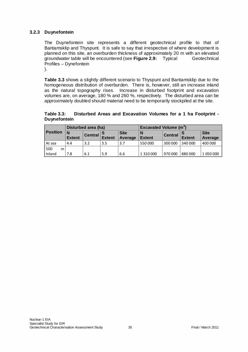
3.2.3 Duynefontein The Duynefontein site represents a different geotechnical profile to that of Bantamsklip and Thyspunt. It is safe to say that irrespective of where development is planned on this site, an overburden thickness of approximately 20 m with an elevated groundwater table will be encountered (see Figure 2.9: Typical Geotechnical Profiles – Dynefontein ). Table 3.3 shows a slightly different scenario to Thyspunt and Bantamsklip due to the homogeneous distribution of overburden. There is, however, still an increase inland as the natural topography rises. Increase in disturbed footprint and excavation volumes are, on average, 180 % and 260 %, respectively. The disturbed area can be approximately doubled should material need to be temporarily stockpiled at the site.
Table 3.3: Disturbed Areas and Excavation Volumes f or a 1 ha Footprint - Duynefontein
Disturbed area (ha) Excavated Volume (m 3) Position N
Extent Central S
Extent Site Average
N Extent
Central S Extent
Site Average
At sea 4.4 3.2 3.5 3.7 550 000 300 000 340 000 400 000
500 m
Inland 7.8 6.1 5.9 6.6 1 310 000 970 000 880 000 1 050 000
Nuclear-1 EIA Specialist Study for EIR Geotechnical Characterisation Assessment Study 36 Final / March 2011
4 ENVIRONMENTAL ASSESSMENT
4.1 Construction Phase
a) Slope failure resulting in safety risks and environmental damage
Excavations at the sites may be subjected to static (normal gravitational) and dynamic (earthquake) loading at any stage within their development. Without due care taken in the design of excavations, dewatering systems and lateral support systems, cut slopes will carry a high risk of failure in an environment where groundwater is encountered1. The extent of the impacts lie within the consequences of failure and the following scenarios are noted:
• Failure of cut slopes in excavations under static conditions (e.g. failure of a slope due to inadequate shear strength particularly below the water table) introduces unacceptable risks to construction personnel whose lives will be at risk.
• Should dynamic loading (earthquakes) trigger liquefaction failure of soil slopes, the resultant damages could be greater as this mode of failure is typically characterised by displacement of larger volumes of saturated soil material, capable of travelling greater distances. The consequences of failure could be catastrophic to safety, the project and to a lesser extent to the environment.
There are no cumulative impacts related to slope stability as, irrespective of the number of nuclear installations being constructed in parallel, slope stability integrity is linked to the thickness of overburden at the sites (and the depth/height of resulting excavations).
b) Excessive site disturbance resulting in environmental damage
In areas where thick, saturated soil horizons need to be removed to reach bedrock, there is a high probability that soil slopes will need to be cut back to flat angles (in the region of 20º) to ensure their integrity. This will result in excavations significantly larger in surface extent than the proposed development footprint. Associated with this will be an increase in excavated volume. There will be an additional disturbed area needed to stockpile/temporarily stockpile this excavated overburden material (spoil).
Cumulative impacts relating to site disturbance at the Duynefontein site may be experienced should the proposed Pebble Bed Modular Reactor Demonstration Power Plant and the proposed Nuclear-1 installation construction programs overlap. In such a scenario, it is reasonable to say that each of these nuclear installations would contribute to independent excavation and spoil footprints, the result being that disturbed footprints (excavation and spoil areas) will be cumulative. It must be noted that it is unlikely that these two nuclear installations would be constructed at the same time. However, Table 4.1 to Error! Reference source not found. assesses the cumulative impacts should this occur. Since the Duynefontein site has a homogenous overburden thickness, there are few mitigation options besides lateral support that will allow a significant reduction in site disturbance. It is not envisaged that two independent nuclear installations will be constructed at the same time on the Thyspunt and Bantamsklip sites simply due to the related economic scale of nuclear
1 In situations where groundwater is not encountered, slope instability will still be an issue but will, in all likelihood, result in a nuisance disturbance only, albeit at potentially high economic cost
Nuclear-1 EIA Specialist Study for EIR Geotechnical Characterisation Assessment Study 37 Final / March 2011
developments. For this reason, there are no cumulative impacts relating to site disturbance on these two sites. Geotechnical resources are not considered irreplaceable in any of the impacts identified.
4.2 Operational Phase
There are no impacts on the natural geotechnical environment envisaged in the operational phase.
4.3 Decommissioning Phase
There are no impacts on the natural geotechnical environment envisaged in the decommissioning phase.
4.4 No-go Alternative
Should it be decided to not construct a nuclear power station none of the above impacts will be introduced. All negative impacts associated with the construction of a nuclear power stationwill therefore be removed. However, Eskom could sell the Thyspunt and Bantamsklip sites, and possibly parts of the Duynefontein site under this scenario and there could therefore be other unforeseen negative impacts arising from different property development scenarios.
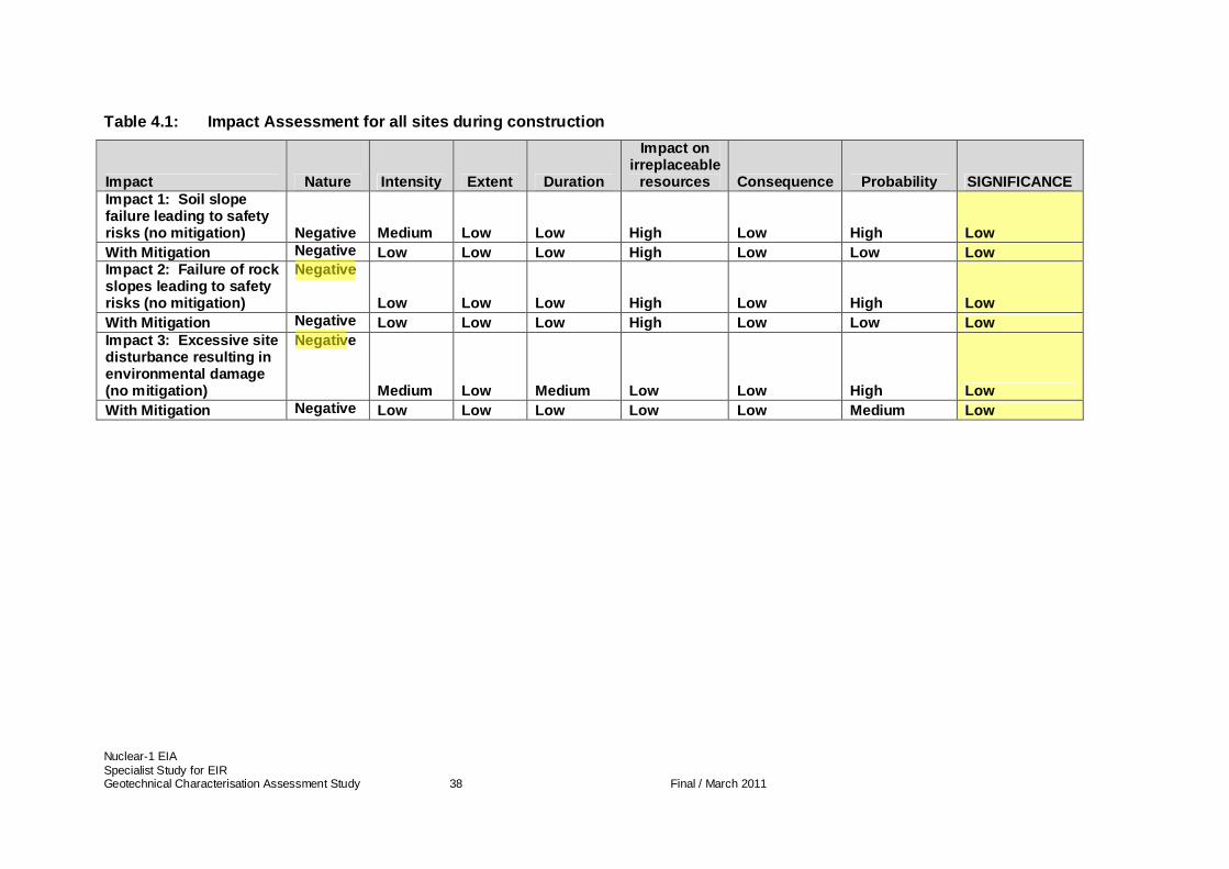
Nuclear-1 EIA Specialist Study for EIR Geotechnical Characterisation Assessment Study 38 Final / March 2011
Table 4.1: Impact Assessment for all sites during c onstruction
Impact Nature Intensity Extent Duration
Impact on irreplaceable
resources Consequence Probability SIGNIFICANCE Impact 1: Soil slope failure leading to safety risks (no mitigation) Negative Medium Low Low High Low High Low With Mitigation Negative Low Low Low High Low Low Low Impact 2: Failure of rock slopes leading to safety risks (no mitigation)
Negative
Low Low Low High Low High Low With Mitigation Negative Low Low Low High Low Low Low Impact 3: Excessive site disturbance resulting in environmental damage (no mitigation)
Negative
Medium Low Medium Low Low High Low With Mitigation Negative Low Low Low Low Low Medium Low
Nuclear-1 EIA Specialist Study for EIR Geotechnical Characterisation Assessment Study 39 Final / March 2011
5 MITIGATION MEASURES
The impacts identified in Section 3 and assessed in Section 4 relate to: • The stability of soil and rock excavations during the construction phase; and • The extent of site disturbance due to foundation excavations probing bedrock, also
during the construction phase. The physical nature of the sites (referred to above as the ‘geotechnical profile’) makes mitigation measures challenging from a design perspective in environments where thick sand overburden is encountered and groundwater is present. The following mitigation objectives and measures almost exclusively rely on the engineering designer’s ability to optimise excavation designs. The mitigation objectives are stated and recommended design solutions described.
5.1 Mitigation objectives
5.1.1 Slope stability
The mitigation objective is to optimise slope angles without placing undue risk on slope stability (and therefore increasing the risk of failure). Site selection aimed at placing the proposed excavation in an area where overburden thickness is least is an obvious mitigation measure that will have significant probability of success at Thyspunt and Bantamsklip, but limited success at Duynefontein.
5.1.2 Site disturbance The mitigation objective is to optimise slope design such that site disturbance is minimised, without increasing the risk of slope failure. Once again, site selection at Thyspunt and Bantamsklip targeting areas of least overburden (i.e. adjacent to the sea) will contribute significantly to reducing site disturbance.
5.2 Recommended mitigation measures
5.2.1 Slope stability
Slope stability will be enhanced by dewatering prior to excavation and by maintaining flatter slope angles. In areas where overburden thickness is less (say 20 m or less), lateral support systems can be optimally designed to maximise slope angles and minimise excavation volumes. The recommended mitigation measures for each of the sites are: • Duynefontein: to explore the feasibility of lateral support systems to retain
approximately 20 m of overburden and minimise excavation volumes, all within an
Nuclear-1 EIA Specialist Study for EIR Geotechnical Characterisation Assessment Study 40 Final / March 2011
effectively dewatered site; • Thyspunt: to place that part of the site to be founded on bedrock near the sea and
minimise the excavation volumes and slope stability risks by siting in areas of less overburden thickness. Once again, this must be done within an effectively dewatered site;
• Bantamsklip: to place the site near the sea and minimise the excavation volumes and slope stability risks by siting in areas of less overburden. This must be done within an effectively dewatered site.
5.2.2 Site disturbance
The mitigation measures proposed for slope stability integrity are mirrored for site disturbance as the aims are to minimize slope height (excavation depth), thus minimising excavation volumes and disturbed area. At Thyspunt and Bantamsklip, site disturbance will be reduced should the site be located within the thinner overburden areas at the sea.
5.2.3 Effectiveness of mitigation measures Placing the proposed plant footprint in areas with less overburden will have a marked effect on reducing impacts. This is not possible at the Duynefontein site as overburden material is homogeneously distributed across the site.
5.2.4 Recommended monitoring and evaluation program me It is imperative that dewatering efficiency is monitored at all times to ensure excavated slope integrity. No other monitoring requirements are necessary.
Nuclear-1 EIA Specialist Study for EIR Geotechnical Characterisation Assessment Study 41 Final / March 2011
6 CONCLUSIONS AND RECOMMENDATIONS
6.1 Conclusions
The site alternatives all have geotechnical profiles that consist of wave cut bedrock terraces overlain by cohesionless sand. In addition, all of the site alternatives have groundwater tables at varying depths. The following site specific information is pertinent: • Thyspunt site :
o The site soil profile varies considerably in thickness as one moves inland, ranging from 0 m thick (at the sea) to almost 60 m thick within the dune area approximately 750 m from the sea;
o The geotechnical properties of these soils are consistent across the site;
o An intergranular aquifer exists at the site, the groundwater table daylights at the sea and there is a variance in depth to the groundwater table in the dune area;
o The soils have no cohesion and will require innovative slope stabilisation techniques when saturated;
o Two dominant geological formations are encountered under the soils, namely the Skurweberg (located nearer the sea) and Goudini Formations (more inland);
o The Goudini rocks are more susceptible to erosion and a buried wave action induced erosion depression orientated north west/south east is evident in the Goudini rocks – this depression houses a cobble/boulder/pebble deposit that influences the direction and extent of groundwater flow locally;
o The quartzitic sandstone dominated Skurweberg Formation is more competent than the carbonaceous sandstone Goudini Formation;
o The difference in geotechnical properties between these two geological formations dictates that the development foundations should not straddle these formations.
• Bantamsklip site :
o The site soil profile varies less in thickness than the Thyspunt site as one moves inland, ranging from 0 m thick (at the sea) to almost 20 m thick within the dune area;
o The geotechnical properties of these soils are consistent across the site, except that significant and random calcretised zones are encountered;
o The groundwater table is situated just above the bedrock; o The soils have no cohesion and when saturated, will require innovative
slope stabilisation techniques, but the presence of calcrete will provide some assistance in this regard;
o The bedrock is dominated by quartzitic sandstones of the Peninsula Formation;
o These quartzitic sandstones are highly jointed, but competent and present a more competent wave cut platform than at Thyspunt;
Nuclear-1 EIA Specialist Study for EIR Geotechnical Characterisation Assessment Study 42 Final / March 2011
• Duynefontein site : o The site soil profile differs from Thyspunt and Bantamsklip in that it is
almost homogeneously 20 m thick everywhere on the site; o The geotechnical properties of these soils are relatively consistent
across the site; o The groundwater table is elevated on this site and occurs between 4
and 10 m below natural ground level; o The soils have no cohesion and when saturated, will require innovative
slope stabilisation techniques; o The overburden sands are underlain by Malmesbury rocks consisting
of a succession of greywacke, hornfels, mudstone, siltsone and shale, all of varying competence;
o The greywacke and hornfels is more competent than the mudstone, siltstone and shale which are all more prone to weathering.
• No go option
Should it be decided to not construct a nuclear power station none of the above impacts associated with the construction of a nuclear power station will be introduced. All associated negative impacts will therefore be removed. However, Eskom could sell the Thyspunt and Bantamsklip sites, and possibly parts of the Duynefontein site under this scenario and there could therefore be other unforeseen negative impacts arising from different property development scenarios. Environmental impacts that could alter the functioning of the natural geotechnical environment during construction are limited to: • Slope instability resulting in safety risks to people and to a lesser extent the
environment; • Geotechnical conditions (and specifically overburden thickness and
groundwater profiles) dictating that large site disturbances will occur in excavations and the disposal of excavation spoil when probing founding level (bedrock).
The impacts related to slope stability imposing safety risks without mitigation measures have low significance and consequences at all of the sites as standard slope stability design will be employed to mitigate instability concerns. Standard slope stabilisation techniques in sands will almost certainly mean that slopes will need to be battered back to flat angles and remain dewatered. Dewatered slopes will have a low risk of liquefaction failure and seismic effects are hence reduced. The overriding impacts result from this as flatter slopes will result in larger volume excavations, larger excavation footprint disturbances and a need for disposal of greater volumes of spoil. The impacts associated with this are of greater significance and can be described as follows: • Duynefontein :
o Without mitigation: medium significance o With mitigation: low significance
• Bantamsklip : o Without mitigation: low significance o With mitigation: low significance

Nuclear-1 EIA Specialist Study for EIR Geotechnical Characterisation Assessment Study 43 Final / March 2011
• Thyspunt : o Without mitigation: medium significance o With mitigation: low - medium significance
Mitigation measures relate to moving the proposed developments closer to the sea at Thyspunt and Bantamsklip to ensure that excavation depths are minimised and to employ lateral support methods where feasible. Lateral support is the only feasible mitigation measure at Duynefontein. Because of the extensive overburden soils present at Thyspunt it is apparent that, even with mitigation, this site may present scenarios where site disturbance and slope stability concerns are possible across the majority of the site.
6.2 Recommendations
Based on the above conclusions, the following recommendations are made: • At the Thyspunt and Bantamsklip sites, the final footprint should be placed as
close to the sea as possible – i.e. in that area where overburden sand thickness is least;
• The development foundations should not straddle the Goudini and Skurweberg Formations at Thyspunt as this will introduce complicated geotechnical design challenges;
• At the Duynefontein site, design alternatives aimed at minimising site disturbance in excavations must be explored.
Nuclear-1 EIA Specialist Study for EIR Geotechnical Characterisation Assessment Study 44 Final / March 2011
7 REFERENCES
1) ESKOM (1994), Nuclear Siting Investigation Programme (NSIP) West Coast
Summary Report, Rev1. 2) ESKOM (1994), Nuclear Siting Investigation Programme (NSIP) Eastern Cape
Summary Report, Rev1. 3) ESKOM (1993), Nuclear Siting Investigation Programme (NSIP) Southern Cape
Summary Report, Rev1. 4) ESKOM (2006), Koeberg Site Safety Report (KSSR) 2006, Chapter 6: Geology
and Seismology, Rev3. Cape Town. 5) Eskom (2006a), Koeberg Site Safety Report. Chapter 9: Hydrology (Rev 3). 6) Eskom (2006b) Koeberg Site Safety Report. Chapter 10: Geology and
Seismology (Rev 3). Cape Town. 7) Eskom (2006c), Koeberg Site Safety Report. Chapter 11: Fresh Water Supply
(Rev 3). Cape Town. 8) AEC [Atomic Energy Corporation of South Africa (Ltd)] (1988a), Regional
Geohydrological Investigations of the Area between the Uilkraals and Heuningnes Rivers, Bredasdorp and Caledon Districts. Investigation for the Siting of Nuclear Power Stations: Eskom Southern Cape Project. Progress Report No. 8. Volume 1.
9) AEC [Atomic Energy Corporation of South Africa (Ltd)] (1988b), Geohydrological Investigations Conducted on the Buffeljags, Bantamsklip and Donkergat Sites. Investigation for the Siting of Nuclear Power Stations: Eskom Southern Cape Project. Progress Report No. 16. Volume 1.
10) AEC [Atomic Energy Corporation of South Africa (Ltd)] (1989), Geology of the Coastal Strip between Gansbaai and Waenhuiskrans: Geological Description of the Project Area.’ Investigation for the Siting of Nuclear Power Stations: Eskom Southern Cape Project. Progress Report No. 10. Volume 1.
11) ESKOM (1988), Investigations for the Siting of Nuclear Power Stations – Progress Report No. 20 AEC Detailed Geology of the De Hoek. Thyspunt and Tony’s Bay Candidate Sites – Eskom Eastern Cape Project.
12) ESKOM (1988), Investigations for the Siting of Nuclear Power Stations – Progress Report No. 12 Detailed Geology of the Donkergat, Bantamsklip and Buffeljags Candidate Sites – Eskom Southern Cape Project.
13) CGS (2008), Nuclear 1 Environmental Impact Assessment and Environmental Management Programme: Specialist Study for Inception Report, Geology and Seismic Hazard.
14) Dames and Moore. July (1973), Koeberg ‘A’ Power Station - Interim Report on Geotechnical Studies.
15) Dames and Moore (1975), Site Investigations Units 1 and 2, Koeberg Nuclear Power Station - Foundation Report.
16) Dames and Moore. May (1976), Geologic Report – Koeberg Nuclear Power Station.
17) Dames and Moore (1977), Supplementary Geologic Report – Koeberg Nuclear Power Station.
18) Dames and Moore (1977), Koeberg Nuclear Power Station – High Voltage Yard – Soils Engineering Investigation; Appendix I – Specification for Civil Engineering Works.
19) Brink A.B.A. (1981), Engineering Geology of Southern Africa, Volume 2, Case History 10, pp124
20) Brink A.B.A. (1985), Engineering Geology of Southern Africa, Volume 4, Case Histories 6 and 7, p 95
21) Eskom. (2006), Koeberg Nuclear Power Station - Site Safety Report – Geology and Seismology Rev 3.

Nuclear-1 EIA Specialist Study for EIR Geotechnical Characterisation Assessment Study 45 Final / March 2011
Company name SRK Consulting
Specialist signature Bruce Engelsman Pr Eng
Date 10 March 2011