Embed Size (px)
Citation preview
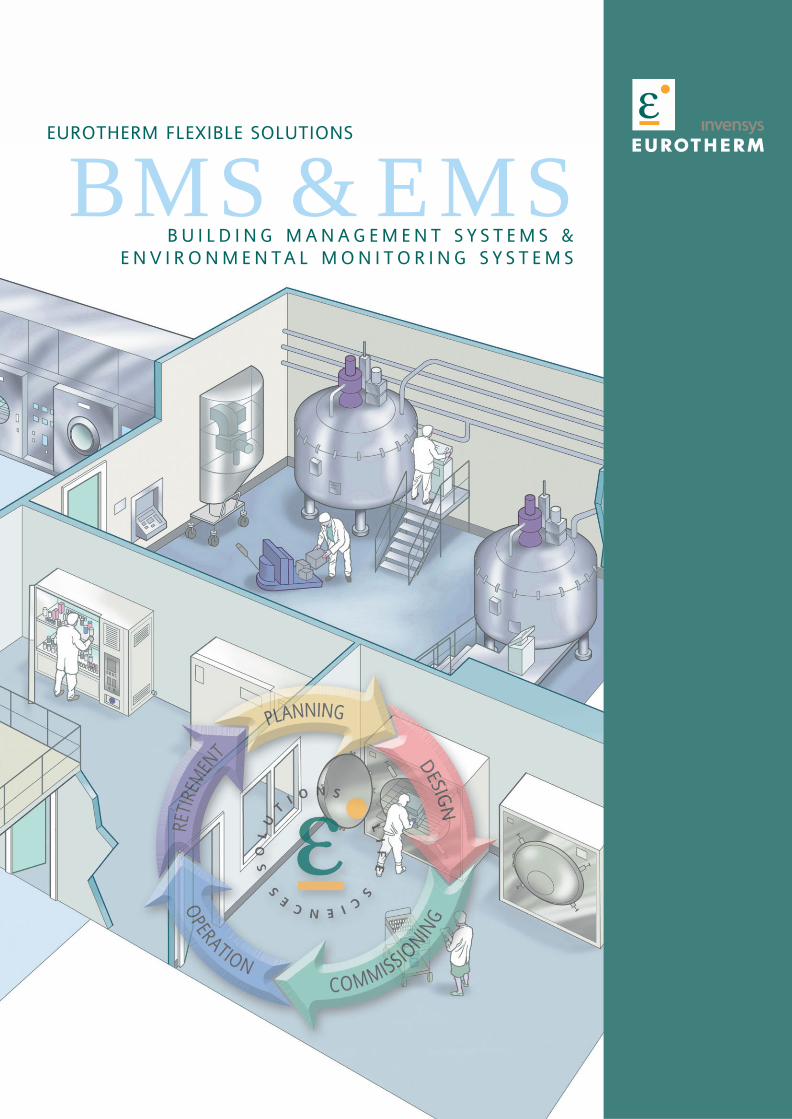
BMS & EMSB U I L D I N G M A N A G E M E N T S Y S T E M S &
E N V I R O N M E N TA L M O N I T O R I N G S Y S T E M S
EUROTHERM FLEXIBLE SOLUTIONS
Why BMS/EMS?
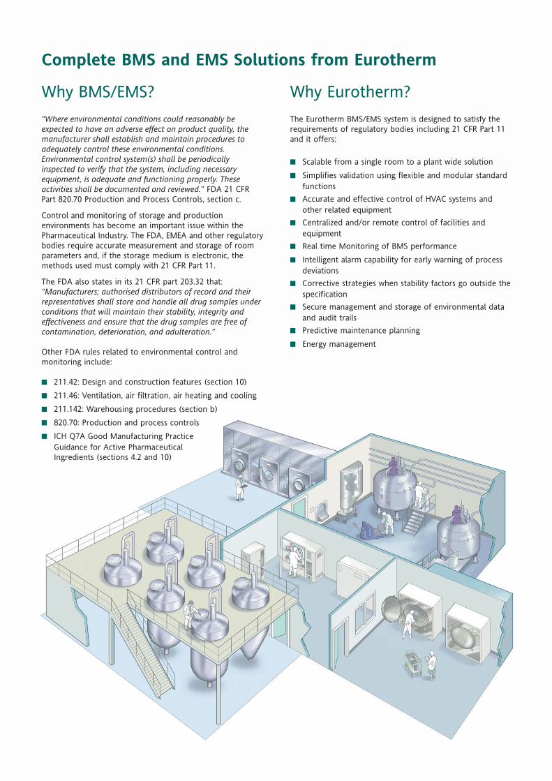
“Where environmental conditions could reasonably beexpected to have an adverse effect on product quality, themanufacturer shall establish and maintain procedures toadequately control these environmental conditions.Environmental control system(s) shall be periodicallyinspected to verify that the system, including necessaryequipment, is adequate and functioning properly. Theseactivities shall be documented and reviewed.” FDA 21 CFRPart 820.70 Production and Process Controls, section c.
Control and monitoring of storage and productionenvironments has become an important issue within thePharmaceutical Industry. The FDA, EMEA and other regulatorybodies require accurate measurement and storage of roomparameters and, if the storage medium is electronic, themethods used must comply with 21 CFR Part 11.
The FDA also states in its 21 CFR part 203.32 that:“Manufacturers; authorised distributors of record and theirrepresentatives shall store and handle all drug samples underconditions that will maintain their stability, integrity andeffectiveness and ensure that the drug samples are free ofcontamination, deterioration, and adulteration.”
Other FDA rules related to environmental control andmonitoring include:
■ 211.42: Design and construction features (section 10)
■ 211.46: Ventilation, air filtration, air heating and cooling
■ 211.142: Warehousing procedures (section b)
■ 820.70: Production and process controls
■ ICH Q7A Good Manufacturing PracticeGuidance for Active PharmaceuticalIngredients (sections 4.2 and 10)
Why Eurotherm?
The Eurotherm BMS/EMS system is designed to satisfy therequirements of regulatory bodies including 21 CFR Part 11and it offers:
■ Scalable from a single room to a plant wide solution
■ Simplifies validation using flexible and modular standardfunctions
■ Accurate and effective control of HVAC systems andother related equipment
■ Centralized and/or remote control of facilities andequipment
■ Real time Monitoring of BMS performance
■ Intelligent alarm capability for early warning of processdeviations
■ Corrective strategies when stability factors go outside thespecification
■ Secure management and storage of environmental dataand audit trails
■ Predictive maintenance planning
■ Energy management
Complete BMS and EMS Solutions from Eurotherm
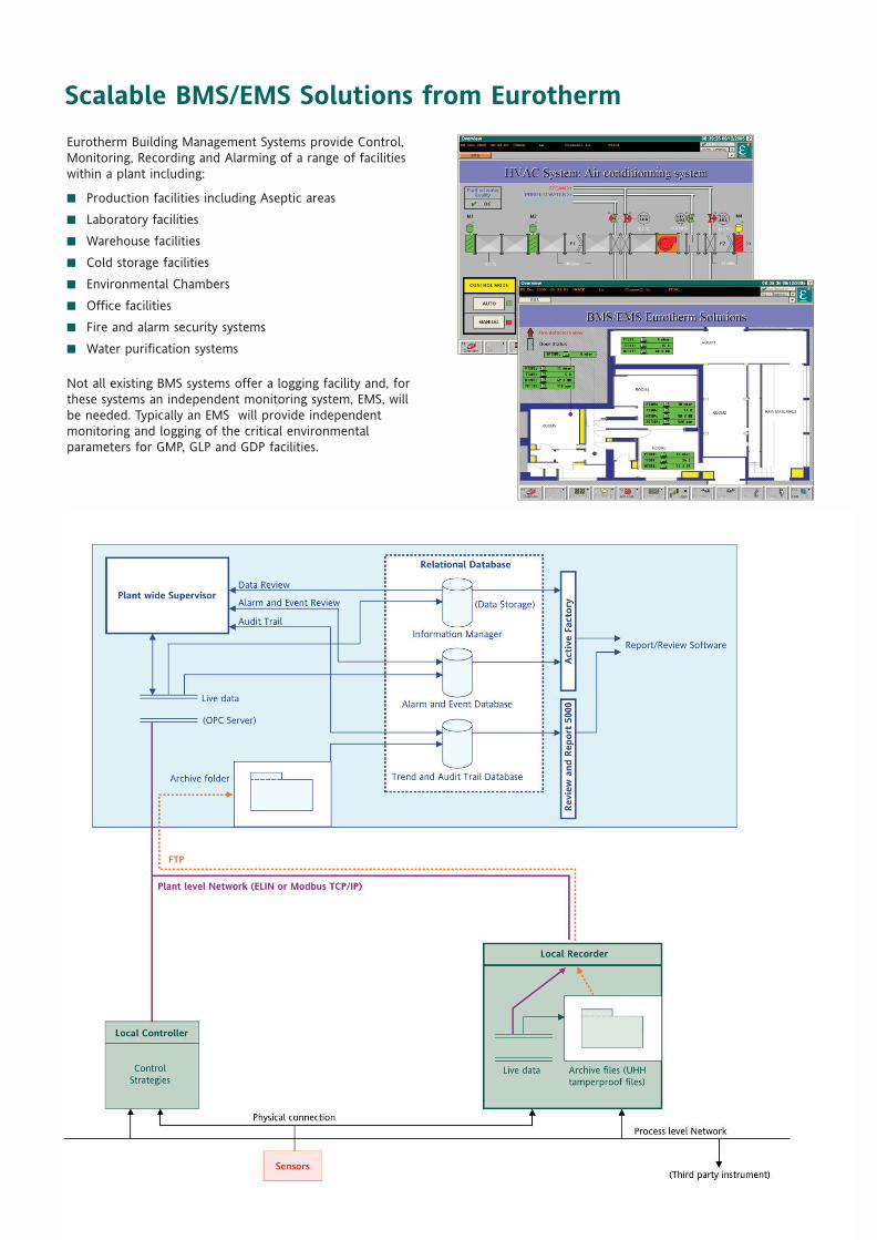
Eurotherm Building Management Systems provide Control,Monitoring, Recording and Alarming of a range of facilitieswithin a plant including:
■ Production facilities including Aseptic areas
■ Laboratory facilities
■ Warehouse facilities
■ Cold storage facilities
■ Environmental Chambers
■ Office facilities
■ Fire and alarm security systems
■ Water purification systems
Not all existing BMS systems offer a logging facility and, forthese systems an independent monitoring system, EMS, willbe needed. Typically an EMS will provide independentmonitoring and logging of the critical environmentalparameters for GMP, GLP and GDP facilities.
Scalable BMS/EMS Solutions from Eurotherm
Eurotherm BMS/EMS StandardModulesEurotherm BMS/EMS solutions are modular and scalable.They offer all the functionality required to control, monitor,record and alarm, for a single room to a plant wideapplication. They are ideal for
■ Implementing a new system
■ Enhancing existing systems
■ EMS for an existing BMS
It offers the options for:
■ Centralised BMS/EMS
■ Network of local standalone BMS/EMS units
■ Combination of centralised and local systems to increaseavailability and ease of use
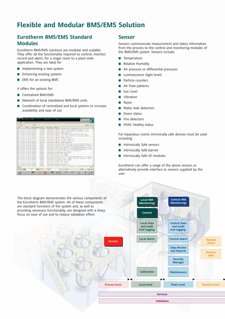
The block diagram demonstrates the various components ofthe Eurotherm BMS/EMS system. All of these componentsare standard functions of the system and, as well asproviding necessary functionality, are designed with a sharpfocus on ease of use and to reduce validation effort.
SensorSensors communicate measurement and status informationfrom the process to the control and monitoring modules ofthe BMS/EMS system. Sensors include:
■ Temperature
■ Relative Humidity
■ Air pressure or differential pressures
■ Luminescence (light level)
■ Particle counters
■ Air Flow patterns
■ Gas Level
■ Vibration
■ Noise
■ Water leak detection
■ Doors status
■ Fire detectors
■ HVAC healthy status
For hazardous rooms intrinsically safe devices must be usedincluding:
■ Intrinsically Safe sensors
■ Intrinsically Safe barrier
■ Intrinsically Safe IO modules
Eurotherm can offer a range of the above sensors oralternatively provide interface to sensors supplied by theuser.
Services
Validation
Sensors
Local HMI(Monitoring)
Local Alarm
Calibration
Control
Maintenance
Data Reviewand Reports
SecurityManager
RemoteHMI
RemoteAlarm
Local Dataand Audit
trail logging
Central HMI(Monitoring)
Central Dataand Audit
trail logging
Central Alarm
Process level Remote levelPlant Level Local level
Flexible and Modular BMS/EMS Solution
MonitoringBMS/EMS offer a wide range of options for monitoring theplant. Information can be monitored locally, centrally andremotely. Access to the system is protected. Users mustlogin to gain access to functionality, defined by their accesslevel.
Plant information is monitored through standard and customdisplays and includes:
■ Live data
■ Mimics with live data
■ Multi language support
Information received from the plant is grouped together invarious forms to allow the users to rapidly access therequired information. The system utilises an easy to use,hierarchical methodology of presenting the necessaryinformation to the users including:
■ Plant overview
■ Area overview
■ Individual room overview
■ Individual control loop view
■ Individual sensor view
■ Grouping by type (e.g. temperature, humidity, pressure)
Data collected from the plant are linked together anddisplayed as trends using online and historical trendingwithin the system. Trended data are available in variousgroups e.g. by room, by type (temperature, pressure etc.)
The monitoring facility also provides the user with access tostandard features of the system according to their accesslevel, including:
■ Access control with password protection for individualuser accounts, inactivity timeout and password expiry
■ Alarms
■ Trends
■ Alarm set point configuration
■ Control parameter configuration
■ Calibration facilities
■ Maintenance facilities
■ Batch displays
■ Electronic signatures
■ Configuration utilities
■ Multi language support
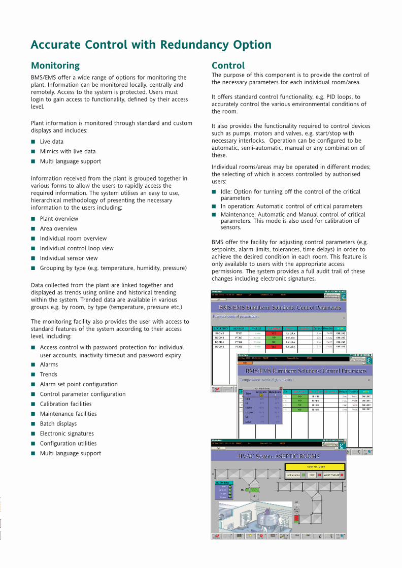
ControlThe purpose of this component is to provide the control ofthe necessary parameters for each individual room/area.
It offers standard control functionality, e.g. PID loops, toaccurately control the various environmental conditions ofthe room.
It also provides the functionality required to control devicessuch as pumps, motors and valves, e.g. start/stop withnecessary interlocks. Operation can be configured to beautomatic, semi-automatic, manual or any combination ofthese.
Individual rooms/areas may be operated in different modes;the selecting of which is access controlled by authorisedusers:
■ Idle: Option for turning off the control of the criticalparameters
■ In operation: Automatic control of critical parameters■ Maintenance: Automatic and Manual control of critical
parameters. This mode is also used for calibration ofsensors.
BMS offer the facility for adjusting control parameters (e.g.setpoints, alarm limits, tolerances, time delays) in order toachieve the desired condition in each room. This feature isonly available to users with the appropriate accesspermissions. The system provides a full audit trail of thesechanges including electronic signatures.
Accurate Control with Redundancy Option
Sensors
Process level
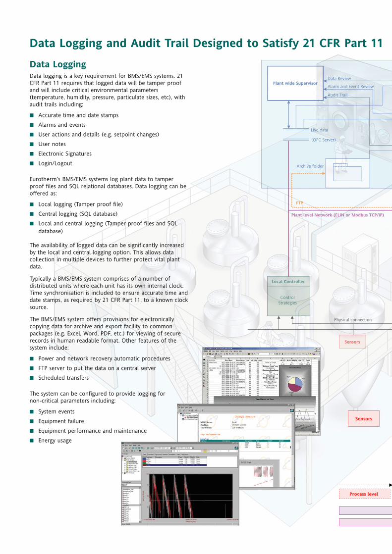
Data LoggingData logging is a key requirement for BMS/EMS systems. 21CFR Part 11 requires that logged data will be tamper proofand will include critical environmental parameters(temperature, humidity, pressure, particulate sizes, etc), withaudit trails including:
■ Accurate time and date stamps
■ Alarms and events
■ User actions and details (e.g. setpoint changes)
■ User notes
■ Electronic Signatures
■ Login/Logout
Eurotherm’s BMS/EMS systems log plant data to tamperproof files and SQL relational databases. Data logging can beoffered as:
■ Local logging (Tamper proof file)
■ Central logging (SQL database)
■ Local and central logging (Tamper proof files and SQLdatabase)
The availability of logged data can be significantly increasedby the local and central logging option. This allows datacollection in multiple devices to further protect vital plantdata.
Typically a BMS/EMS system comprises of a number ofdistributed units where each unit has its own internal clock.Time synchronisation is included to ensure accurate time anddate stamps, as required by 21 CFR Part 11, to a known clocksource.
The BMS/EMS system offers provisions for electronicallycopying data for archive and export facility to commonpackages (e.g. Excel, Word, PDF, etc.) for viewing of securerecords in human readable format. Other features of thesystem include:
■ Power and network recovery automatic procedures
■ FTP server to put the data on a central server
■ Scheduled transfers
The system can be configured to provide logging fornon-critical parameters including:
■ System events
■ Equipment failure
■ Equipment performance and maintenance
■ Energy usage
Data Logging and Audit Trail Designed to Satisfy 21 CFR Part 11

Alarms and Events ReportingAn important feature of the BMS/EMS system is its Alarmsand Events functionality. All alarms and events are timestamped and logged for long term retention and validationto 21 CFR Part 11. Individual plant data can be configured tohave one or a combination of the following alarms:
■ Absolute alarms■ Deviation alarms■ Rate of Change alarms■ Delayed alarms■ Excursion alarms
The system can be configured to provide other alarmsincluding;
■ Sensor break■ Equipment failures■ Network failure■ Maintenance and calibration alarm
Alarms can be configured as critical, non-critical or as anevent. Critical alarms will require manual acknowledgementand non-critical will be auto-acknowledged. Alarm selectionand setpoint settings are available to the users with theappropriate access level and critical alarms can beconfigured to require an Electronic Signature for changes.Alarm acknowledgement and all changes to alarm settingsare automatically logged as required by 21 CFR part 11.
All alarms and events are reported through local, central,and remote HMI panels. They are displayed in the AlarmSummary and Alarm History pages which provide a sortfacility for the information. Alarms can be grouped by theircriticality and function to ensure individual alarms can bequickly accessed.
Other features of the BMS/EMS alarm system include:
■ Audible alarm notification
■ Notification of alarm conditions to designated users ona designated telephone number
■ Local printing of alarms and events
Local HMI(Monitoring)
Local Alarm
Calibration
Control
Maintenance
Data Reviewand Reports
SecurityManager
RemoteHMI
RemoteAlarm
Local Dataand Audit
trail logging
Central HMI(Monitoring)
Central Dataand Audit
trail logging
Central Alarm
Remote levelPlant Level Local level
Services
Validation
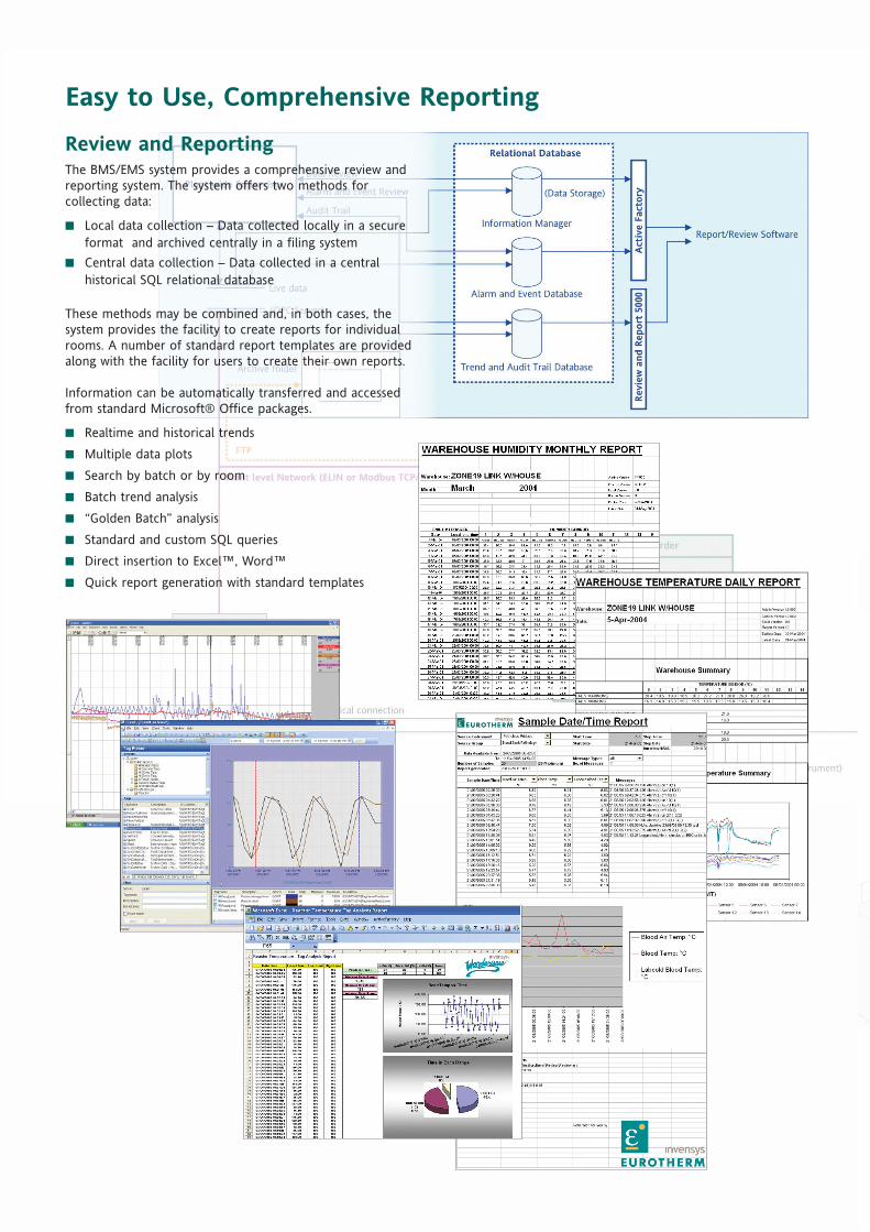
Review and ReportingThe BMS/EMS system provides a comprehensive review andreporting system. The system offers two methods forcollecting data:
■ Local data collection – Data collected locally in a secureformat and archived centrally in a filing system
■ Central data collection – Data collected in a centralhistorical SQL relational database
These methods may be combined and, in both cases, thesystem provides the facility to create reports for individualrooms. A number of standard report templates are providedalong with the facility for users to create their own reports.
Information can be automatically transferred and accessedfrom standard Microsoft® Office packages.
■ Realtime and historical trends
■ Multiple data plots
■ Search by batch or by room
■ Batch trend analysis
■ “Golden Batch” analysis
■ Standard and custom SQL queries
■ Direct insertion to Excel™, Word™
■ Quick report generation with standard templates
Easy to Use, Comprehensive Reporting
Sensors
Local HMI(Monitoring)
Local Alarm
Calibration
Control
Maintenance
Data Reviewand Reports
SecurityManager
RemoteHMI
RemoteAlarm
Local Dataand Audit
trail logging
Central HMI(Monitoring)
Central Dataand Audit
trail logging
Central Alarm
Process level Remote levelPlant Level Local level
Services
Validation
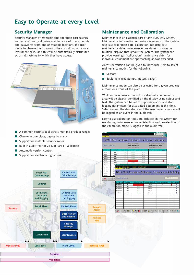
Security ManagerSecurity Manager offers significant operation cost savingsand ease of use by allowing maintenance of user accountsand passwords from one or multiple locations. If a userneeds to change their password they can do so on a localinstrument or PC and this will be automatically distributedacross all systems to which they have access.
■ A common security tool across multiple product ranges
■ Change in one place, deploy to many
■ Support for multiple security zones
■ Built-in audit trail for 21 CFR Part 11 validation
■ Automatic version control
■ Support for electronic signatures
Maintenance and CalibrationMaintenance is an essential part of any BMS/EMS system.Maintenance information on various elements of the system(e.g. last calibration date, calibration due date, lastmaintenance date, maintenance due date) is shown onmultiple displays throughout the system. The system canprovide warnings if calibration/maintenance dates forindividual equipment are approaching and/or exceeded.
Access permission can be given to individual users to selectmaintenance modes for the following:
■ Sensors
■ Equipment (e.g. pumps, motors, valves)
Maintenance mode can also be selected for a given area e.g.a room or a zone of the plant.
While in maintenance mode the individual equipment orarea will be clearly identified on the display using colour andtext. The system can be set to suppress alarms and stoplogging parameters for associated equipment at this time.Selection and the de-selection of the maintenance mode willbe logged as an event in the audit trail.
Easy to use calibration tools are included in the system foruse during maintenance mode. Selection and de-selection ofthe calibration mode is logged in the audit trail.
Easy to Operate at every Level

Remote Alarm NotificationNominated users can be quickly notified of alarm conditionsvia the telephone system. The system offers:
■ Real-time alarm notification triggered from the plant system
■ Ensured the delivery of the messages
■ Easy to configure tools
■ Login facilities and security patterns
■ Redundancy options
Remote MonitoringRemote users, including off-site, can access plantinformation via a secure web portal.
■ Remote real-time data visualisation
■ Multi language facilities
■ Support for multiple windows
■ Integrated information from diverse data sources
ServicesServices need to be provided from the beginning of theproject, though the project development andcommissioning, and for the lifetime of the system.Eurotherm offers a complete range of services such as:
■ Expertise to assist with the User RequirementSpecification
■ Project, Application and Validation engineering
■ Commissioning (e.g. calibration) and qualificationengineering
■ Training courses coveringproducts, control theory,validation etc.
■ Helpdesk and on call services
■ Product services
Sensors
Local HMI(Monitoring)
Local Alarm
Calibration
Control
Maintenance
Data Reviewand Reports
SecurityManager
RemoteHMI
RemoteAlarm
Local Dataand Audit
trail logging
Central HMI(Monitoring)
Central Dataand Audit
trail logging
Central Alarm
Process level Remote levelPlant Level Local level
Services
Validation
Total Lifecycle Support
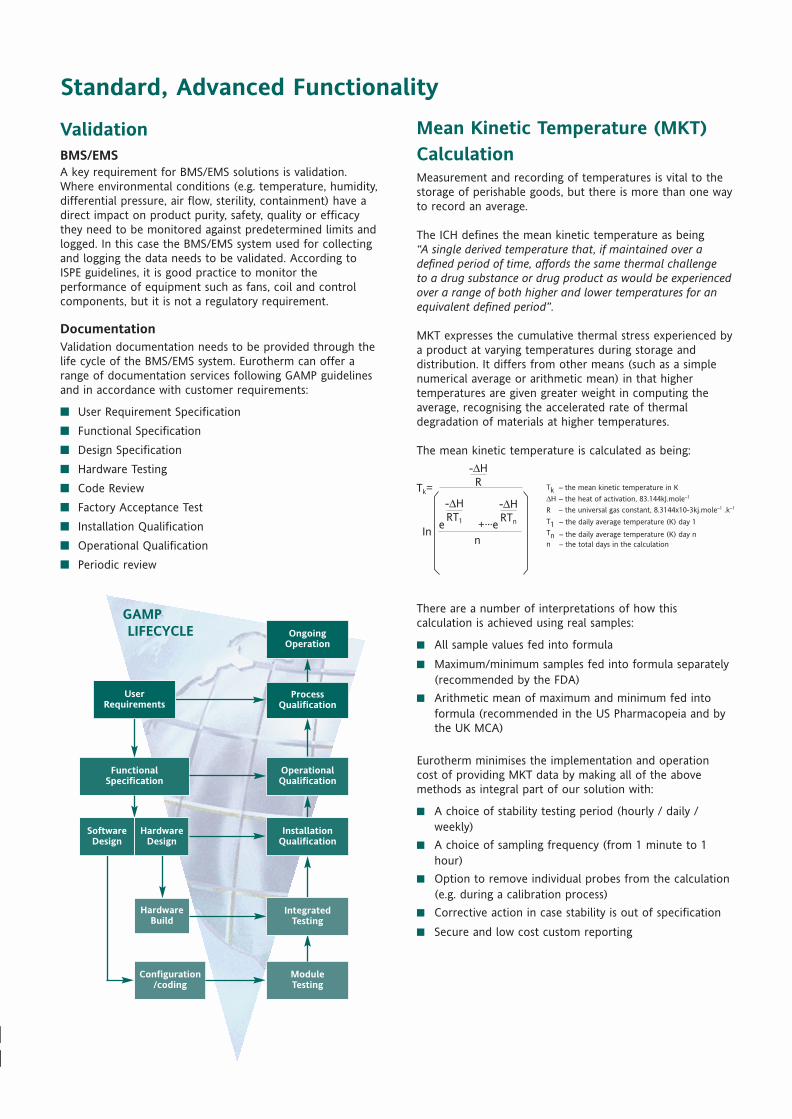
Validation BMS/EMSA key requirement for BMS/EMS solutions is validation.Where environmental conditions (e.g. temperature, humidity,differential pressure, air flow, sterility, containment) have adirect impact on product purity, safety, quality or efficacythey need to be monitored against predetermined limits andlogged. In this case the BMS/EMS system used for collectingand logging the data needs to be validated. According toISPE guidelines, it is good practice to monitor theperformance of equipment such as fans, coil and controlcomponents, but it is not a regulatory requirement.
Documentation Validation documentation needs to be provided through thelife cycle of the BMS/EMS system. Eurotherm can offer arange of documentation services following GAMP guidelinesand in accordance with customer requirements:
■ User Requirement Specification
■ Functional Specification
■ Design Specification
■ Hardware Testing
■ Code Review
■ Factory Acceptance Test
■ Installation Qualification
■ Operational Qualification
■ Periodic review
FunctionalSpecification
OperationalQualification
ModuleTesting
Configuration/coding
HardwareBuild
Ongoing Operation
GAMPLIFECYCLE
InstallationQualification
Process Qualification
User Requirements
Hardware Design
Software Design
Integrated Testing
– the mean kinetic temperature in K
– the heat of activation, 83.144kJ.mole–1
– the daily average temperature (K) day 1
– the daily average temperature (K) day n– the total days in the calculation
– the universal gas constant, 8.3144x10⁻³kj.mole–1 .k–1
Mean Kinetic Temperature (MKT) CalculationMeasurement and recording of temperatures is vital to thestorage of perishable goods, but there is more than one wayto record an average.
The ICH defines the mean kinetic temperature as being“A single derived temperature that, if maintained over adefined period of time, affords the same thermal challengeto a drug substance or drug product as would be experiencedover a range of both higher and lower temperatures for anequivalent defined period”.
MKT expresses the cumulative thermal stress experienced bya product at varying temperatures during storage anddistribution. It differs from other means (such as a simplenumerical average or arithmetic mean) in that highertemperatures are given greater weight in computing theaverage, recognising the accelerated rate of thermaldegradation of materials at higher temperatures.
The mean kinetic temperature is calculated as being:
There are a number of interpretations of how thiscalculation is achieved using real samples:
■ All sample values fed into formula
■ Maximum/minimum samples fed into formula separately(recommended by the FDA)
■ Arithmetic mean of maximum and minimum fed intoformula (recommended in the US Pharmacopeia and bythe UK MCA)
Eurotherm minimises the implementation and operationcost of providing MKT data by making all of the abovemethods as integral part of our solution with:
■ A choice of stability testing period (hourly / daily /weekly)
■ A choice of sampling frequency (from 1 minute to 1hour)
■ Option to remove individual probes from the calculation(e.g. during a calibration process)
■ Corrective action in case stability is out of specification
■ Secure and low cost custom reporting
Standard, Advanced Functionality
Eurotherm: International sales and service
Represented by:
AUSTRALIA SydneyEurotherm Pty. Ltd.Telephone (+61 2) 9838 0099Fax (+61 2) 9838 9288E-mail [email protected]
AUSTRIA ViennaEurotherm GmbHTelephone (+43 1) 7987601Fax (+43 1) 7987605E-mail [email protected]
BELGIUM & LUXEMBURG HuyEurotherm S.A/N.V.Telephone (+32) 85 274080Fax (+32 ) 85 274081E-mail [email protected]
BRAZIL Campinas-SPEurotherm Ltda.Telephone (+5519) 3707 5333Fax (+5519) 3707 5345E-mail [email protected]
DENMARK Copenhagen Eurotherm Danmark A/STelephone (+45 70) 234670Fax (+45 70) 234660E-mail [email protected]
FINLAND AboEurotherm FinlandTelephone (+358) 22506030Fax (+358) 22503201
FRANCE Lyon Eurotherm Automation SATelephone (+33 478) 664500Fax (+33 478) 352490E-mail [email protected]
GERMANY LimburgEurotherm Deutschland GmbHTelephone (+49 6431) 2980Fax (+49 6431) 298119E-mail [email protected]
HONG KONG & CHINA Eurotherm Limited AberdeenTelephone (+85 2) 28733826Fax (+85 2) 28700148E-mail [email protected]
Guangzhou OfficeTelephone (+86 20) 8755 5936Fax (+86 20) 8755 5831
Beijing OfficeTelephone (+86 10) 6762 0936Fax (+86 10) 6762 0931
Shanghai OfficeTelephone (+86 21) 6352 6406Fax (+86 21) 6352 7351
INDIA Chennai Eurotherm India LimitedTelephone (+91 44) 24961129Fax (+91 44) 24961831E-mail [email protected]
IRELAND DublinEurotherm Ireland LimitedTelephone (+353 1) 469180Fax (+353 01) 4691300E-mail [email protected]
ITALY ComoEurotherm S.r.lTelephone (+39 31) 975111Fax (+39 31) 977512Telex 380893 EUROTH IE-mail [email protected]
KOREA Seoul Eurotherm Korea LimitedTelephone (+82 31) 2738507Fax (+82 31) 2738508E-mail [email protected]
NETHERLANDS Alphen a/d RynEurotherm B.V.Telephone (+31 172) 411752Fax (+31 172) 417260E-mail [email protected]
NORWAY Oslo Eurotherm A/STelephone Oslo (+47 67) 592170Fax (+47 67) 118301E-mail [email protected]
SPAIN MadridEurotherm España SATelephone (+34 91) 6616001Fax (+34 91) 6619093E-mail [email protected]
SWEDEN MalmoEurotherm ABTelephone (+46 40) 384500Fax (+46 40) 384545E-mail [email protected]
SWITZERLAND FreienbachEurotherm Produkte (Schweiz) AGTelephone (+41 55) 4154400Fax (+41 55) 4154415E-mail [email protected]
UNITED KINGDOM WorthingEurotherm LimitedTelephone (+44 1903) 268500Fax (+44 1903) 265982E-mail [email protected] www.eurotherm.co.uk
U.S.A Leesburg VAEurotherm Inc.Telephone (+1 703) 443 0000Fax (+1 703) 669 1300E-mail [email protected] www.eurotherm.com
ED43
Eurotherm is also represented in thefollowing countries:
AzerbaijanBahrainBangladeshBulgariaCanadaCzech RepublicEgyptGeorgiaGreeceHungaryIndonesiaIranIraqIsraelJapanJordanKazakhstanKenyaKuwaitLatviaLithuaniaMalaysiaMexico
New ZealandNigeriaOmanPakistanPhilippinesPolandPuerto RicoQatarRomaniaRussiaSaudi ArabiaSingaporeSlovak RepublicSloveniaSouth AfricaSri LankaThailandTurkeyTurkmenistanUAEUkraineUzbekistan
© Copyright Eurotherm Limited 2005
Invensys, Eurotherm, the Eurotherm logo and Wonderware are trademarks of Invensys plc, its subsidiaries and affiliates. All other brands may be trademarks of their respective owners.
All rights are strictly reserved. No part of this document may be reproduced, modified, or transmitted in any form by any means, nor may it be stored in a retrieval systemother than for the purpose to act as an aid in operating the equipment to which the document relates, without the prior written permission of Eurotherm limited.
Eurotherm Limited pursues a policy of continuous development and product improvement. The specifications in this document may therefore be changed without notice.The information in this document is given in good faith, but is intended for guidance only. Eurotherm Limited will accept no responsibility for any losses arising from errors in this document.
Part No. HA029194 Issue 1 Printed in England 01.06
Understanding and providing local support is a key part of Eurotherm’s business. Complementing worldwide Eurotherm offices are awhole range of partners and a comprehensive technical support team… a soothing melody to ensure you get a service you will wantto go back to.