Embed Size (px)
Citation preview

Physical and OperationalSecurity for Transfer Switches
Evaluating Device Security from the Inside Out
White Paper 117

Physical and Operational Security for Transfer SwitchesEvaluating Device Security from the Inside Out
Backup power equipment that supplies electricity to load equipment must operate whenever needed to assure life safety and business continuity. To ensure that only authorized users can set-up and control equipment, manufacturers provide security features in transfer switches and other critical power devices. This document summarizes select security features commonly found within these devices.
Backup power systems are used to mitigate or avoid the effects of public power outages on facilities and the services that they host. This assures that customers, patients, and end-users experience little or no impact to services on which they depend. Assurance is lost if backup systems fail in ways that leave facilities without power. The following examples demonstrate problems that could result from misconfigured or improperly operated equipment:
• Decreased Availability: If a device were configured or operated improperly, a backup system may not supply power when needed.
• Increased Cost: If a device did not shut down backup power when utility power is restored, a generator will run longer than intended, resulting in unnecessary fuel cost and wear.
• Equipment Damage: Digital equipment downstream of an open-transition Automatic Transfer Switch (ATS) could be affected by repeated short-term transfers. In delayed transfer applications, improper delay settings could result in electrical and mechanical damage.
Each of these scenarios could result from device manipulation by malicious or incompetent actors. To prevent such access, power devices are commonly equipped with security features to ensure that only authorized users will configure and control devices.
BACKGROUND INFORMATION
2

The figure shows three principle components of many automatic transfer switches: (1) the transfer switch mechanism that transfer loads from one power source to another, (2) the controller that automates its operations, and (3) the communication gateway that is fitted to many switches to provide communication, monitoring, and control functions. Signals from communication gateways can pass through various system boundaries.
COMMON PROTECTIONS
The following sections summarize key transfer switch features for securing the respective boundaries, working from the transfer mechanism outward.
Locked Enclosures
In their most essential form, a transfer switches consist of (1) a transfer mechanism that switches loads between acceptable power sources and (2) a device to control it (Figure 2). Controllers provide multiple functions associated with load transfers, including signaling engines to start, confirming that acceptable power is present on the alternate source, and initiating retransfer when the primary source is reenergized.
In automatic transfer switches, electronic programs control switch operation. The controller may feature a port for updating firmware. In many switches, this is accessible only by opening the equipment enclosure to access the port. Front-facing ports require mechanical or electronic protection. Preventing unauthorized access is thus the first method for ensuring that firmware can be loaded only by authorized persons.
Figure 1: System Boundaries
Figure 2: Essential ATS
To understand how to secure power devices, it is useful to review the boundaries of the physical and electronic systems in which they are placed. For instance, switches are installed within buildings or at outdoor locations, and therefore can be subject to physical inputs through any Human Machine Interface (HMI) provided. They can also be connected to digital systems for communications, monitoring, and control. A conceptual model is shown on Figure 1.
A DEVICE SECURITY MODEL
SerialProtocols
Controller
Transfer Mechanism
Comm.Gateway
Lock
ed
Equ
ipm
ent
Doo
rP
assw
ord
Pro
tect
ed
HM
I
Faci
lity
LAN
Pub
licIn
tern
et
Inte
rnal
S
eria
l N
etw
ork
Lock
edR
oom
Com
pany
LA
N
ATS
Ded
icat
ed
Eth
erne
tPo
wer
Net
wor
k
IP Protocols
C
L
O
U
D
BMSDigital Communications
Controller
ATS Mech.
3

The solution is very simple: Lock or secure the enclosure’s door or access panel (Figure 3), then make sure that only authorized personnel can access the necessary keys or tools. Doing so puts the transfer switch at the first equipment boundary in Figure 1. Figure 4 shows an ATS in an outdoor enclosure.
Figure 3: ATS with Enclosure Figure 4: ATS with HMI
Secured HMI
A Human-Machine Interface represents the second system boundary in the aforementioned model. The following sections describe HMI capabilities and two measures for securing equipment controls.
HMI Capabilities
An HMI or control panel typically provides capability for users to initiate transfers manually (Figure 4). This is useful for testing and maintenance, and for preemptive transfer to backup power when events such as storms are anticipated. Manual transfer must be conducted by competent persons authorized to perform these actions. Importantly, transfer switches are designed to close only on live power sources presenting acceptable characteristics.
Other aspects of transfer switch operation are implemented through the HMI. Operating parameters are specified via user-defined settings entered through the HMI and stored in controllers. If inappropriate settings are used, performance or reliability could be affected. For instance, diesel generators must achieve a minimum operating temperature for a minimum duration to avoid wet-stacking, a condition where unburned fuel residues accumulate in engine exhaust systems, decreasing performance and reliability. Likewise, a facility may elect to stay on generator power for a dedicated amount of time to ensure stability of the reenergized primary power source prior to retransfer. Users configure the various delay settings in controllers to ensure that these and other parameters will promote proper operation and avoid equipment and service degradation. For these reasons, HMIs must be protected from unauthorized access. Two HMI examples are shown in Figure 5.
Figure 5: The left-hand unit is a pushbutton LED type. At right is a color touch display interface with animation capabilities.
Controller
Enclosure w/ Locked Door
ATS Mech.
Controller
HMI
ATS Mech.
4
Protect with Passwords
Most people are familiar with password protection schemes. In their simplest form, a single code enables any user to access a device. More commonly, users are provided access credentials that consist of a unique username and a unique password. When entered, software compares this information to stored user data. If the entered information matches user and password data on file, the user is granted access to the device. If matching information is not found, the user is not granted access. This level of protection reduces the opportunity for unauthorized users to set equipment controls and manipulate settings.
Adding a third data field to user credential increases security capabilities and eases security administration. Designating one of several Levels of Access for each user provides control over the types of action each person will be capable of executing. For example, a three-level system could use this successive format:
Secure Firmware
Measures for securing firmware in controllers and other power equipment components range according to device technologies and designs. Nevertheless, two methods for maintaining firmware security include (1) installing updates when necessary and (2) ensuring that only authorized firmware is used.
Manufacturers can issue firmware updates when security weaknesses or emerging threats are identified. Because these security updates can protect equipment from the latest cybersecurity threats such as viruses and malware, it is especially important to implement them on network-connected power equipment. Updates can also remedy exploitable vulnerabilities in firmware when they are found.
Manufacturers can also increase security by using digitally signed firmware and bootloaders. A “bootloader” is a utility program that loads application software into a digital processor. Where digital signatures are used, the bootloader will check that the digital signature in the new firmware version matches the one embedded in the bootloader by the manufacturer. This can prevent introduction of unauthorized firmware into the equipment.
Password-based user credentials can protect against unauthorized access when essential rules are observed: (1) access and authorization level are granted solely to those with an actual need to execute the associated actions; and (2) access level is only granted to persons who are fully competent to perform the associated activities. Notably, some equipment uses mechanical keys in lieu of password protections.
Importantly, access credentials must be updated immediately when personnel present security risks or are reassigned or separated from a facility. Malicious events sometimes occur as the result of actions by disgruntled employees. Likewise, it is also important that password protection schemes are fully implemented. Leaving passwords set at factory defaults invites unauthorized use. For this reason, manufacturers may design controllers to automatically require new passwords when equipment is initially installed. Devices with WI-FI and Bluetooth communication capabilities require associated security and password protections to prevent unauthorized electronic access.
• Operations Staff – Capabilities needed by facility staff to conduct routine operations and tests
• Facility Manager – Adds capabilities to adjust key settings and technically sensitive parameters
• Facility Engineer – Adds capabilities to adjust parameters essential to the design and configuration of the power equipment and systems
5
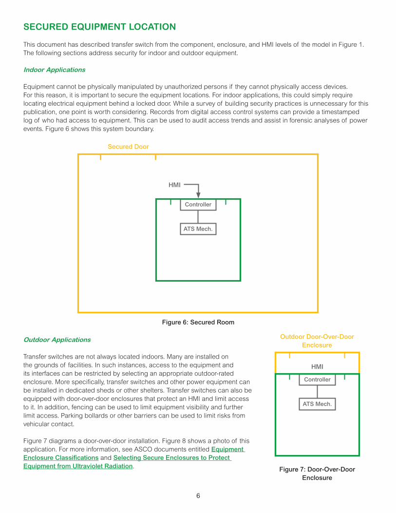
SECURED EQUIPMENT LOCATION
This document has described transfer switch from the component, enclosure, and HMI levels of the model in Figure 1. The following sections address security for indoor and outdoor equipment.
Indoor Applications
Equipment cannot be physically manipulated by unauthorized persons if they cannot physically access devices. For this reason, it is important to secure the equipment locations. For indoor applications, this could simply require locating electrical equipment behind a locked door. While a survey of building security practices is unnecessary for this publication, one point is worth considering. Records from digital access control systems can provide a timestamped log of who had access to equipment. This can be used to audit access trends and assist in forensic analyses of power events. Figure 6 shows this system boundary.
Figure 6: Secured Room
Outdoor Applications
Transfer switches are not always located indoors. Many are installed on the grounds of facilities. In such instances, access to the equipment and its interfaces can be restricted by selecting an appropriate outdoor-rated enclosure. More specifically, transfer switches and other power equipment can be installed in dedicated sheds or other shelters. Transfer switches can also be equipped with door-over-door enclosures that protect an HMI and limit access to it. In addition, fencing can be used to limit equipment visibility and further limit access. Parking bollards or other barriers can be used to limit risks from vehicular contact.
Figure 7 diagrams a door-over-door installation. Figure 8 shows a photo of this application. For more information, see ASCO documents entitled Equipment Enclosure Classifications and Selecting Secure Enclosures to Protect Equipment from Ultraviolet Radiation. Figure 7: Door-Over-Door
Enclosure
Controller
HMI
ATS Mech.
Secured Door
Controller
HMI
ATS Mech.
Outdoor Door-Over-Door Enclosure
6

PROTECTING COMMUNICATIONS
Network communications present a host of security concern that require the services of qualified professionals. However, portions of security solutions are applied at the device level. The following sections briefly outline select measures.
I/O and Serial Communications
The simplest communications occur using digital input-output and serial protocols. For instance, a facility may rely on an RS-485 circuit to communicate signaling to a remote panel or a building management system. The far end of the circuit may connect to a wall-mounted panel in the same room as the device, a device in another room, or to a serial communications network dedicated to facility equipment. Facilities must evaluate the remote device and its location for all of the security provisions already described herein. Providing a secure equipment enclosure, password protection, secure firmware, and a secure facility are important measures to consider for remote devices. Figure 9 illustrates how connecting a communications wire to a transfer switch controller crosses multiple system boundaries.
Figure 9: Serial Application
Controller
ATS Mech.
Lock
ed
Equ
ipm
ent
Doo
rP
assw
ord
Pro
tect
ed
HM
I
Inte
rnal
S
eria
l N
etw
ork
Lock
edR
oom
Remote HMI or Internal BMS
Figure 8: These views show the double-door construction of a secure Type 3R cabinet. When fully closed and secured, the controls are protected from unauthorized access.
7

Ethernet Communications
Ethernet communications enable a wide range of communication features over a variety of communication protocols. Some Ethernet communications can interact with a dedicated power network, a facility’s Local Area Network (LAN), a company’s IT security firewall, and potentially with the public Internet. Securing these networks is the focus of an entire world-wide industry, and facilities should consult qualified experts for appropriate solutions. The following sections describe a few elementary provisions that can be made on the device-side, where a communication gateway serves as the interface to these systems (Figure 10).
Figure 10: Ethernet Application
DoS Attack-Resistant Communication Module
A common cyberthreat is a Denial-of-Service (DoS) attack. These use multiple network resources to send service requests to a power device gateway or other target. Without appropriate provisions, the actions required to handle these requests can consume and overwhelm the computing resources of the device.
Communication modules can be designed or configured to dedicate only a limited set of resources to service requests. For example, a communication module designed to dedicate only 30% of its processing capacity to managing service requests will always have 70% of its capacity available for other operations. This arrangement can prevent the device from being overwhelmed during a DoS attack. It also increases its ability to recover because operating resources remain available for that purpose.
Signal Encryption
Encrypting communications between a device and its network protects data streams. Some power communication gateways and power devices can be configured to use encryption technologies. This involves providing appropriate encryption features and encryption keys in devices at both ends of a communication pathway. Both the controller and the distant network communication device can encrypt and decrypt data signals according to a shared key. When available, using an encryption standard limits the ability of intruders to access the underlying data.
User Activity Logging
Some devices can log activities conducted by each user. The records can be reviewed to evaluate procedural compliance. Logged information can also be used forensically to evaluate the timeline of power-related events and may track unauthorized access attempts.
Controller
ATS Mech.
Comm.Gateway
System Boundaries
Ethernet To Network
8
SUMMARY
When securing transfer switches and other poser system devices, a layered security model enables facilities to look from the inside of a device outward to the various system boundaries that impact physical and operational security. Common-sense security measures such as securing equipment enclosures and rooms and applying password protections mitigate routine threats to reliable operation.
Security of I/O and serial communications can be enhanced by applying the same types of protections at remote panel and remote terminal locations. Device-level initiatives for Ethernet-connected equipment include provisions for resisting Denial-of-Service attacks, encrypting communicated data, and logging user activity.
9

ASCO Power Technologies - Global Headquarters160 Park AvenueFlorham Park, NJ 07932Tel: 800 800 ASCO
© 2020 ASCO Power Technologies. All Rights Reserved. Life Is On Schneider Electric is a trademark and the property of Schneider Electric SE, its subsidiaries and affiliated companies.