Embed Size (px)
Citation preview
12
Fan coilsUniversal and floor installationFCX
Fan coils for heating, cooling, and dehumidifying. FCX is designed to maintain in time the set temperature, ensuring very low sound levels. Installed in any type of plant 2/4 tubes and in combination with any of the heat generator even at low temperatures.Thanks to the availability of different versions, with front or lower air intake, with standard battery or increased, for hori-zontal or vertical installation, it is easy to choose the optimal solution for any need.
- Vertical installation: FCX-A: vertical free-standing with switch FCX-AS: vertical free-standing without switch. Compatible
with the VMF system FCX-ACT: vertical free standing with electronic thermostat FCX-APC: (FCX 22, 24, 32, 34, 36, 42, 44, 50, 54, 56, 62,
64, 82, 84) vertical free-standing with electronic thermostat and Plasmacluster purifier
FCX-B: front suction, without selector. Compatible with the VMF system
- Vertical and horizontal installation: FCX-U: universal floor or wall/ceiling mounting.
Adjustable air distribution grille, except for models 62, 64, 82, 84 and 102. Compatible with the VMF system
FCX-UA: universal floor or wall/ceiling mounting. Grille with fixed fins. Compatible with the VMF system
FCX-UE: universal floor or wall/ceiling mounting with direct expansion coil. Adjustable air distribution grille, except for models 62, 82 and 102.
• Versions standar coil (FCX 17, 22, 32, 36, 42, 50, 56, 62, 82 and 102)
• Versions increased coil (FCX 24, 34, 44, 54, 64, and 84)• 3-speed ventilating unit• Full compliance with the accident prevention standards
• Rounded line• Automatic fan coil switch-off with closure of the air distri-
bution grille• Broad range of controls• Metallic protective cabinet with rustproofing polyester
paint• Quiet operation• Low loss of charge in the heat exchange batteries• Electric motors with permanently inserted condensers• Ease of installation and maintenance• Air filter easy to remove and clean• Extractable shrouds for easy, effective cleaning• Water connections can be reversed during installation
phase
Features
Aermecparticipate in the EUROVENT program: FCHthe products are present on the sitewww.eurovent-certification.com
housing: RAL 9002head and feet: RAL 7044
VERSION AVAILABLE SIZESFCX A 17 22 24 32 34 36 42 44 50 54 56 62 64 82 84 102FCX AS 17 22 24 32 34 36 42 44 50 54 56 62 64 82 84 102FCX ACT 17 22 24 32 34 36 42 44 50 54 56 62 64 82 84 102FCX APC - 22 24 32 34 36 42 44 50 54 56 62 64 82 84 -
FCX B 17 22 24 32 34 36 42 44 50 54 56 62 64 82 84 102
FCX U 17 22 24 32 34 36 42 44 50 54 56 62 64 82 84 102FCX UA 17 22 24 32 34 36 42 44 50 54 56 - - - - -FCX UE - 22 - 32 - - 42 - 50 - - 62 - 82 - 102
• AMP: kit for the wall mounting installation of versions FCX U and UE.
• BC: Auxiliary condensate drip tray. Use the BC 5-6 tray accessory if horizontal, or BC 4 if vertical.
• BV: Single row hot water coil. Not available for 4-row versions or those with Plasmacluster.
• DSC4: Condensate drainage device for use when natural run-off is not possible.
• PC: Sheet metal panel to close rear of unit.• RX: Armoured electric coil with safety thermo-
stat. (Requires a thermostat with heater manage-ment). Not available for 4-row versions or those with Plasmacluster.
• SE: Manually operated fresh air intake louver.• SIT 3 - 5: Thermostat Interface Cards. They allow
the creation of a network of fan coils (max. 10) commanded by a central control panel (selector or thermostat).
SIT3: commands the 3 fan speeds and must be installed on each fan coil of the network; receives the commands from the selector or the
SIT5 card. SIT5: commands the 3 fan speeds and up to 2
valves (four pipes systems); sends the commands of the thermostat to the fan coils network.
• SW3: water temperature probe that gives the auto-matic season change feature to electronic thermo-stats supplied with water-side change over.
• SWA: SWA external probe accessory (length L = 6m). The probe detects the temperature of the ambient air if connected to the connector (A) of the panel FMT21; the ambient air temperature probe incorporated in the panel is automatically deactivated. Detects the temperature of the water in the system, for ventilation consent, if connected to the connector (W) of the FMT21 panel. Two SWA probes can be connected to the panel FMT21 simultaneously.
• VCF: the kit contains a motorised 3-way valve with insulating shell, plus coupling and pipes in insulated copper. For 3/4-row and 1-row coils (BV). Combine the SW3 probe with FCX ACT, too. Versions with
230V and 24V~50Hz power supply.• VCFD: Kit consisting of powered 2-way valve,
copper couplings and pipes. For 3/4-row and 1-row coils (BV). Combine the SW3 probe with FCX ACT, too. Versions with 230V and 24V~50Hz power supply.
• VCF_X4: The valve kits are designed for fan coil units with single coil, installed in a 4 pipe sys-tem with the "Cooling" and "Heating" circuits totally separated. The kit consists of 2 valves of 3-way 4 port connection complete with electro-thermal actuators, insulating shells for the valves and associated hydraulic piping. VCF1X4L Valve kit for left hand connection fan coil units. VCF1X4R Valve kit for right hand connection fan coil units. Power supply: 230V ~ 50Hz.
• ZX: Feet for floor-standing installations for A-AS-ACT-APC models.
• Control panels(1) and VMF System(2): the charac-teristics are described on the appropriate card.
Accessories
FCX_A
FCX-UZX
13
Accessories Size Versions17 22 24 32 34 36 42 44 50 54 56 62 64 82 84 102
FMT10 • FMT21 (1) • • • • • • • • • • • • • • • • AS-B-U-UAKTLM (1) • • • • • • • • • • • • • • • • AS-B-U-UAPTI (1) • • • • • • • • • • • • • • • • AS-B-UA-U(62 - 102)PX • PX2 • PX2C6 (1) (3) • • • • • • • • • • • • • • • • AS-B-U-UAPXBI• PXAI (1) • • • • • • • • • • • • • • • • AS-B-U-UAPXAE (1) • • • • • • • • • • • • • • • • AS-B-U-UAPXAR (1) • • • • • • • • • • • • • • • • AS-B-U-UATF1 (1) • • • • • • • • • • • • • • • • AS-B-U-UATPF (1) • • • • • • • • • • • • • • • • AS-B-U-UAWMT05• WMT06 • WMT10 (1) • • • • • • • • • • • • • • • • AS-B-U-UAVMF-E4 • VMF-E4D (2) • • • • • • • • • • • • • • • • AS-B-U-UAVMF-E2 (2) • • • • • • • • • • • • • • • • AS-B-UA-U(62 - 102)VMF-E0 • VMF-E1 (2) • • • • • • • • • • • • • • • • AS-B-U-UAAMP • • • • • • • • • • • • • • • • U-UA-UEAMP20 • • • • • • • • • • • U-UA-UE
BC4 • • • • • • • • • • • • • • • • A-AS-ACT-APC-B-U-UA-UE5 • • • • • • • • • • • U-UA-UE6 • • • • • U-UA-UE
BV
117 (4) • A-AS-B-U-UA-UE122 (4) • A-AS-B-U-UA-UE132 (4) • • A-AS-B-U-UA-UE142 (4) • • • A-AS-B-U-UA-UE162 (4) • • • A-AS-B-U-UA-UE
DSC4 (5)(6) • • • • • • • • • • • • • • • • A-AS-ACT-APC-B-U-UA-UE
PC
17 • A-AS-ACT-APC-B-UA18 • U-UE22 • • A-AS-ACT-APC-B-UA23 • • U-UE32 • • • A-AS-ACT-APC-B-UA33 • • • U-UE42 • • • • • A-AS-ACT-APC-B-UA43 • • • • • U-UE62 • • • • • A-AS-ACT-B-U-UA-UE
RX
17 (4) • AS-B-U-UA22 (4) • AS-B-U-UA-UE32 (4) • • AS-B-U-UA-UE42 (4) • AS-B-U-UA-UE52 (4) • • AS-B-U-UA-UE62 (4) • • • AS-B-U-UA-UE
SE
15X • A-AS-ACT-APC20X • • A-AS-ACT-APC30X • • • A-AS-ACT-APC40X • • • • • A-AS-ACT-APC80X • • • • • A-AS-ACT-APC
SIT3 • • • • • • • • • • • • • • • • AS-B-U-UA-UE5 • • • • • • • • • • • • • • • • AS-B-U-UA-UE
SW3 • • • • • • • • • • • • • • • • AS-B-U-UASWA • • • • • • • • • • • • • • • • AS-B-U-UA
VCF
1X4L - 1X4R (7) • • • AS-B-U-UA2X4L - 2X4R (7) • • • • • • • • AS-B-U-UA3X4L - 3X4R (7) • • • • • AS-B-U-UA41-4124 (7)(8) • • • AS-ACT-APC-B-U-UA42-4224 (7)(8) • • • • • • • • AS-ACT-APC-B-U-UA43-4324 (7)(8) • • • • • AS-ACT-APC-B-U-UA44-4424 (7)(8)(9) • • • • • • • AS-B-U-UA45-4524 (7)(8)(9) • • • AS-B-U-UA
VCFD
1-124 (7)(8) • • • AS-ACT-APC-B-U-UA2-224 (7)(8) • • • • • • • • AS-ACT-APC-B-U-UA3-324 (7)(8) • • • • • AS-ACT-APC-B-U-UA4-424 (7)(8)(9) • • • • • • • • • • AS-B-U-UA
ZX5 • • • • • • • • • • • A-AS-ACT-APC6 • • • • • A-AS-ACT-APC
(1)(2) The characteristics are described on the appropriate card.(3) PX2C6, PX2 panel in multiple 6-piece pack.(4) Accessoires is not available in the model with Plasmacluster filter(5) The DSC4 accessory is not compatible with AMP and BC4_5_6 accessories(6) DSC4 and accessoires VMF-system tray cannot be installed together on a single fan coil.(7) The VCF/VCFD valve and the BC4 tray cannot be installed together on a single fan coil.(8) = VCF4124-4224-4324-4424-4524 / VCFD124-224-324-424 they are 24V(9) Only for the BV 1-row coil accessory.
14
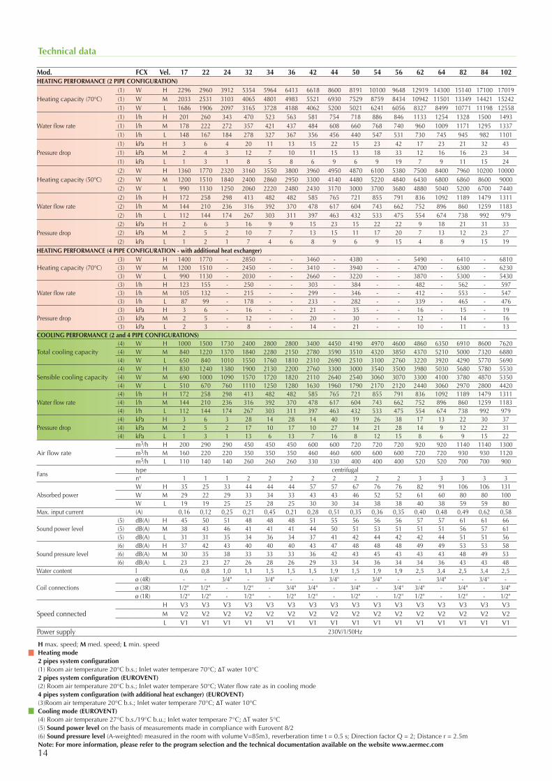
Technical data
Mod. FCX Vel. 17 22 24 32 34 36 42 44 50 54 56 62 64 82 84 102HEATING PERFORMANCE (2 PIPE CONFIGURATION)
Heating capacity (70°C)(1) W H 2296 2960 3912 5354 5964 6413 6618 8600 8191 10100 9648 12919 14300 15140 17100 17019 (1) W M 2033 2531 3103 4065 4801 4983 5521 6930 7529 8759 8434 10942 11501 13349 14421 15242 (1) W L 1686 1906 2097 3165 3728 4188 4062 5200 5021 6241 6056 8327 8499 10771 11198 12558
Water flow rate(1) l/h H 201 260 343 470 523 563 581 754 718 886 846 1133 1254 1328 1500 1493 (1) l/h M 178 222 272 357 421 437 484 608 660 768 740 960 1009 1171 1295 1337 (1) l/h L 148 167 184 278 327 367 356 456 440 547 531 730 745 945 982 1101
Pressure drop(1) kPa H 3 6 4 20 11 13 15 22 15 23 42 17 23 21 32 43 (1) kPa M 2 4 3 12 7 10 11 15 13 18 33 12 16 16 23 34 (1) kPa L 1 3 1 8 5 8 6 9 6 9 19 7 9 11 15 24
Heating capacity (50°C)(2) W H 1360 1770 2320 3160 3550 3800 3960 4950 4870 6100 5380 7500 8400 7960 10200 10000 (2) W M 1200 1510 1840 2400 2860 2950 3300 4140 4480 5220 4840 6430 6800 6860 8600 9000 (2) W L 990 1130 1250 2060 2220 2480 2430 3170 3000 3700 3680 4880 5040 5200 6700 7440
Water flow rate(2) l/h H 172 258 298 413 482 482 585 765 721 855 791 836 1092 1189 1479 1311 (2) l/h M 144 210 236 316 392 370 478 617 604 743 662 752 896 860 1259 1183 (2) l/h L 112 144 174 267 303 311 397 463 432 533 475 554 674 738 992 979
Pressure drop(2) kPa H 2 6 3 16 9 9 15 23 15 22 22 9 18 21 31 33 (2) kPa M 2 5 2 10 7 7 13 15 11 17 20 7 13 12 23 27 (2) kPa L 1 2 1 7 4 6 8 9 6 9 15 4 8 9 15 19
HEATING PERFORMANCE (4 PIPE CONFIGURATION - with additional heat exchanger)
Heating capacity (70°C)(3) W H 1400 1770 - 2850 - - 3460 - 4380 - - 5490 - 6410 - 6810(3) W M 1200 1510 - 2450 - - 3410 - 3940 - - 4700 - 6300 - 6230(3) W L 990 1130 - 2030 - - 2660 - 3220 - - 3870 - 5300 - 5430
Water flow rate(3) l/h H 123 155 - 250 - - 303 - 384 - - 482 - 562 - 597(3) l/h M 105 132 - 215 - - 299 - 346 - - 412 - 553 - 547(3) l/h L 87 99 - 178 - - 233 - 282 - - 339 - 465 - 476
Pressure drop(3) kPa H 3 6 - 16 - - 21 - 35 - - 16 - 15 - 19(3) kPa M 2 5 - 12 - - 20 - 30 - - 12 - 14 - 16(3) kPa L 2 3 - 8 - - 14 - 21 - - 10 - 11 - 13
COOLING PERFORMANCE (2 and 4 PIPE CONFIGURATIONS)
Total cooling capacity(4) W H 1000 1500 1730 2400 2800 2800 3400 4450 4190 4970 4600 4860 6350 6910 8600 7620(4) W M 840 1220 1370 1840 2280 2150 2780 3590 3510 4320 3850 4370 5210 5000 7320 6880(4) W L 650 840 1010 1550 1760 1810 2310 2690 2510 3100 2760 3220 3920 4290 5770 5690
Sensible cooling capacity(4) W H 830 1240 1380 1900 2130 2200 2760 3300 3000 3540 3500 3980 5030 5680 5780 5530(4) W M 690 1000 1090 1570 1720 1820 2110 2640 2540 3060 3070 3300 4100 3780 4870 5350(4) W L 510 670 760 1110 1250 1280 1630 1960 1790 2170 2120 2440 3060 2970 2800 4420
Water flow rate (4) l/h H 172 258 298 413 482 482 585 765 721 855 791 836 1092 1189 1479 1311(4) l/h M 144 210 236 316 392 370 478 617 604 743 662 752 896 860 1259 1183(4) l/h L 112 144 174 267 303 311 397 463 432 533 475 554 674 738 992 979
Pressure drop(4) kPa H 3 6 3 28 14 28 14 40 19 26 38 17 13 22 30 37(4) kPa M 2 5 2 17 10 17 10 27 14 21 28 14 9 12 22 31(4) kPa L 1 3 1 13 6 13 7 16 8 12 15 8 6 9 15 22
Air flow ratem3/h H 200 290 290 450 450 450 600 600 720 720 720 920 920 1140 1140 1300m3/h M 160 220 220 350 350 350 460 460 600 600 600 720 720 930 930 1120m3/h L 110 140 140 260 260 260 330 330 400 400 400 520 520 700 700 900
Fanstype centrifugaln° 1 1 1 2 2 2 2 2 2 2 2 3 3 3 3 3
Absorbed powerW H 35 25 33 44 44 44 57 57 67 76 76 82 91 106 106 131W M 29 22 29 33 34 33 43 43 46 52 52 61 60 80 80 100W L 19 19 25 25 28 25 30 30 34 38 38 40 38 59 59 80
Max. input current (A) 0,16 0,12 0,25 0,21 0,45 0,21 0,28 0,51 0,35 0,36 0,35 0,40 0,48 0,49 0,62 0,58
Sound power level(5) dB(A) H 45 50 51 48 48 48 51 55 56 56 56 57 57 61 61 66(5) dB(A) M 38 43 46 41 41 41 44 50 51 53 51 51 51 56 57 61(5) dB(A) L 31 31 35 34 36 34 37 41 42 44 42 42 44 51 51 56
Sound pressure level(6) dB(A) H 37 42 43 40 40 40 43 47 48 48 48 49 49 53 53 58(6) dB(A) M 30 35 38 33 33 33 36 42 43 45 43 43 43 48 49 53(6) dB(A) L 23 23 27 26 28 26 29 33 34 36 34 34 36 43 43 48
Water content l 0,6 0,8 1,0 1,1 1,5 1,5 1,5 1,9 1,5 1,9 1,9 2,5 3,4 2,5 3,4 2,5
Coil connectionsø (4R) - - 3/4" - 3/4" - - 3/4" - 3/4" - - 3/4" - 3/4" -ø (3R) 1/2" 1/2" - 1/2" - 3/4" 3/4" - 3/4" - 3/4" 3/4" - 3/4" - 3/4"ø (1R) 1/2" 1/2" - 1/2" - 1/2" 1/2" - 1/2" - 1/2" 1/2" - 1/2" - 1/2"
Speed connectedH V3 V3 V3 V3 V3 V3 V3 V3 V3 V3 V3 V3 V3 V3 V3 V3M V2 V2 V2 V2 V2 V2 V2 V2 V2 V2 V2 V2 V2 V2 V2 V2L V1 V1 V1 V1 V1 V1 V1 V1 V1 V1 V1 V1 V1 V1 V1 V1
Power supply 230V/1/50Hz
H max. speed; M med. speed; L min. speedHeating mode2 pipes system configuration(1) Room air temperature 20°C b.s.; Inlet water temperare 70°C; ΔT water 10°C2 pipes system configuration (EUROVENT)(2) Room air temperature 20°C b.s.; Inlet water temperare 50°C; Water flow rate as in cooling mode4 pipes system configuration (with additional heat exchanger) (EUROVENT)(3)Room air temperature 20°C b.s.; Inlet water temperare 70°C; ΔT water 10°CCooling mode (EUROVENT)(4) Room air temperature 27°C b.s./19°C b.u.; Inlet water temperare 7°C; DT water 5°C(5) Sound power level on the basis of measurements made in compliance with Eurovent 8/2(6) Sound pressure level (A-weighted) measured in the room with volume V=85m3, reverberation time t = 0.5 s; Direction factor Q = 2; Distance r = 2.5mNote: For more information, please refer to the program selection and the technical documentation available on the website www.aermec.com
Aermec S.p.A.Via Roma, 996 - 37040 Bevilacqua (VR) - ItalyTelephone 0442633111 - Telefax 044293577www.aermec.com
15Aermec reserves the right to make all modification deemed necessary for improving the product at any time with any modification of technical data.
Cod
.: SF
CX
UY.
19 /
1501
A
B C
A
BC
B
A
C
D
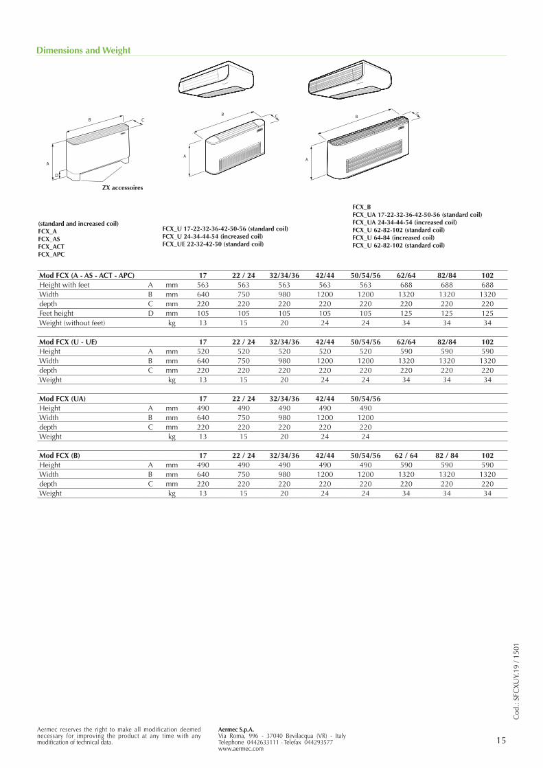
Dimensions and Weight
Mod FCX (A - AS - ACT - APC) 17 22 / 24 32/34/36 42/44 50/54/56 62/64 82/84 102Height with feet A mm 563 563 563 563 563 688 688 688Width B mm 640 750 980 1200 1200 1320 1320 1320depth C mm 220 220 220 220 220 220 220 220Feet height D mm 105 105 105 105 105 125 125 125Weight (without feet) kg 13 15 20 24 24 34 34 34
Mod FCX (U - UE) 17 22 / 24 32/34/36 42/44 50/54/56 62/64 82/84 102Height A mm 520 520 520 520 520 590 590 590Width B mm 640 750 980 1200 1200 1320 1320 1320depth C mm 220 220 220 220 220 220 220 220Weight kg 13 15 20 24 24 34 34 34
Mod FCX (UA) 17 22 / 24 32/34/36 42/44 50/54/56Height A mm 490 490 490 490 490Width B mm 640 750 980 1200 1200depth C mm 220 220 220 220 220Weight kg 13 15 20 24 24
Mod FCX (B) 17 22 / 24 32/34/36 42/44 50/54/56 62 / 64 82 / 84 102Height A mm 490 490 490 490 490 590 590 590Width B mm 640 750 980 1200 1200 1320 1320 1320depth C mm 220 220 220 220 220 220 220 220Weight kg 13 15 20 24 24 34 34 34
(standard and increased coil)FCX_AFCX_ASFCX_ACTFCX_APC
ZX accessoires
FCX_U 17-22-32-36-42-50-56 (standard coil)FCX_U 24-34-44-54 (increased coil)FCX_UE 22-32-42-50 (standard coil)
FCX_BFCX_UA 17-22-32-36-42-50-56 (standard coil)FCX_UA 24-34-44-54 (increased coil)FCX_U 62-82-102 (standard coil)FCX_U 64-84 (increased coil)FCX_U 62-82-102 (standard coil)
16
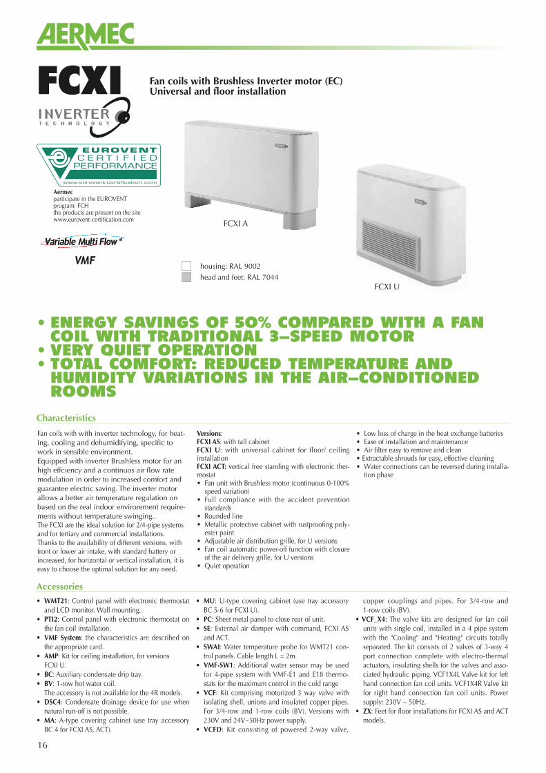
Fan coils with Brushless Inverter motor (EC)Universal and floor installationFCXI
Fan coils with with inverter technology, for heat-ing, cooling and dehumidifying, specific to work in sensible environment.Equipped with inverter Brushless motor for an high effciency and a continuos air flow rate modulation in order to increased comfort and guarantee electric saving. The inverter motor allows a better air temperature regulation on based on the real indoor envirorement require-ments without temperature swinging.. The FCXI are the ideal solution for 2/4-pipe systems and for tertiary and commercial installations.Thanks to the availability of different versions, with front or lower air intake, with standard battery or increased, for horizontal or vertical installation, it is easy to choose the optimal solution for any need.
Versions:FCXI AS: with tall cabinetFCXI U: with universal cabinet for floor/ ceiling installationFCXI ACT: vertical free standing with electronic ther-mostat• Fan unit with Brushless motor (continuous 0-100%
speed variation)• Full compliance with the accident prevention
standards• Rounded line• Metallic protective cabinet with rustproofing poly-
ester paint• Adjustable air distribution grille, for U versions• Fan coil automatic power-off function with closure
of the air delivery grille, for U versions• Quiet operation
• Low loss of charge in the heat exchange batteries• Ease of installation and maintenance• Air filter easy to remove and clean• Extractable shrouds for easy, effective cleaning• Water connections can be reversed during installa-
tion phase
Characteristics
• ENERGY SAVINGS OF 50% COMPARED WITH A FAN COIL WITH TRADITIONAL 3-SPEED MOTOR
• VERY QUIET OPERATION• TOTAL COMFORT: REDUCED TEMPERATURE AND HUMIDITY VARIATIONS IN THE AIR-CONDITIONED ROOMS
Accessories
FCXI U
FCXI A
housing: RAL 9002
head and feet: RAL 7044
Aermecparticipate in the EUROVENTprogram: FCHthe products are present on the sitewww.eurovent-certification.com
• WMT21: Control panel with electronic thermostat and LCD monitor. Wall mounting.
• PTI2: Control panel with electronic thermostat on the fan coil installation.
• VMF System: the characteristics are described on the appropriate card.
• AMP: Kit for ceiling installation, for versions FCXI U.• BC: Auxiliary condensate drip tray.• BV: 1-row hot water coil. The accessory is not available for the 4R models.• DSC4: Condensate drainage device for use when
natural run-off is not possible.• MA: A-type covering cabinet (use tray accessory
BC 4 for FCXI AS, ACT).
• MU: U-type covering cabinet (use tray accessory BC 5-6 for FCXI U).
• PC: Sheet metal panel to close rear of unit.• SE: External air damper with command, FCXI AS
and ACT.• SWAI: Water temperature probe for WMT21 con-
trol panels. Cable length L = 2m.• VMF-SW1: Additional water sensor may be used
for 4-pipe system with VMF-E1 and E18 thermo-stats for the maximum control in the cold range
• VCF: Kit comprising motorized 3 way valve with isolating shell, unions and insulated copper pipes. For 3/4-row and 1-row coils (BV). Versions with 230V and 24V~50Hz power supply.
• VCFD: Kit consisting of powered 2-way valve,
copper couplings and pipes. For 3/4-row and 1-row coils (BV).
• VCF_X4: The valve kits are designed for fan coil units with single coil, installed in a 4 pipe system with the "Cooling" and "Heating" circuits totally separated. The kit consists of 2 valves of 3-way 4 port connection complete with electro-thermal actuators, insulating shells for the valves and asso-ciated hydraulic piping. VCF1X4L Valve kit for left hand connection fan coil units. VCF1X4R Valve kit for right hand connection fan coil units. Power supply: 230V ~ 50Hz.
• ZX: Feet for floor installations for FCXI AS and ACT models.
17
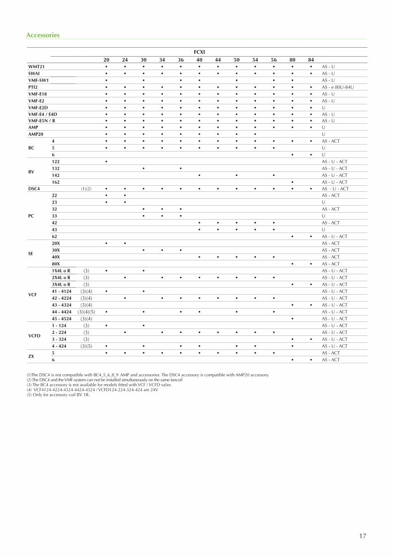
Accessories
(1)The DSC4 is not compatible with BC4_5_6_8_9 AMP and accessories. The DSC4 accessory is compatible with AMP20 accessory. (2) The DSC4 and the VMF-system can not be installed simultaneously on the same fancoil(3) The BC4 accessory is not available for models fitted with VCF / VCFD valve.(4) VCF4124-4224-4324-4424-4524 / VCFD124-224-324-424 are 24V(5) Only for accessory coil BV 1R.
FCXI20 24 30 34 36 40 44 50 54 56 80 84
WMT21 • • • • • • • • • • • • AS - USWAI • • • • • • • • • • • • AS - UVMF-SW1 • • • • • • • AS - UPTI2 • • • • • • • • • • • • AS - e 80U-84UVMF-E18 • • • • • • • • • • • • AS - UVMF-E2 • • • • • • • • • • • • AS - UVMF-E2D • • • • • • • • • • • • UVMF-E4 / E4D • • • • • • • • • • • • AS - UVMF-E5N / B • • • • • • • • • • • • AS - UAMP • • • • • • • • • • • • U AMP20 • • • • • • • • • U
BC4 • • • • • • • • • • • • AS - ACT5 • • • • • • • • • • U 6 • • U
BV
122 • AS - U - ACT132 • • AS - U - ACT142 • • • AS - U - ACT162 • AS - U - ACT
DSC4 (1)(2) • • • • • • • • • • • • AS - U - ACT
PC
22 • • AS - ACT23 • • U32 • • • AS - ACT33 • • • U42 • • • • • AS - ACT43 • • • • • U62 • • AS - U - ACT
SE
20X • • AS - ACT30X • • • AS - ACT40X • • • • • AS - ACT80X • • AS - ACT
VCF
1X4L o R (3) • • AS - U - ACT2X4L o R (3) • • • • • • • • AS - U - ACT3X4L o R (3) • • AS - U - ACT41 - 4124 (3)(4) • • AS - U - ACT42 - 4224 (3)(4) • • • • • • • • AS - U - ACT43 - 4324 (3)(4) • • AS - U - ACT44 - 4424 (3)(4)(5) • • • • • • AS - U - ACT45 - 4524 (3)(4) • AS - U - ACT
VCFD
1 - 124 (3) • • AS - U - ACT2 - 224 (3) • • • • • • • • AS - U - ACT3 - 324 (3) • • AS - U - ACT4 - 424 (3)(5) • • • • • • • AS - U - ACT
ZX5 • • • • • • • • • • AS - ACT6 • • AS - ACT
18
Technical data
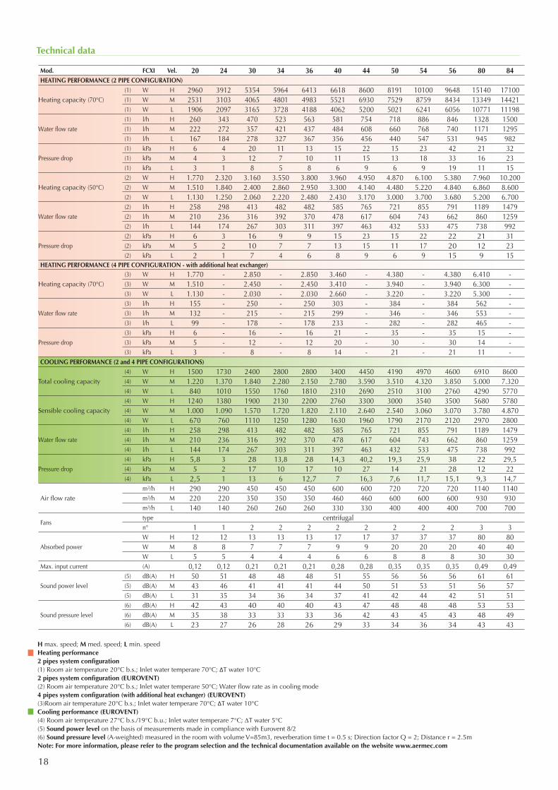
Mod. FCXI Vel. 20 24 30 34 36 40 44 50 54 56 80 84HEATING PERFORMANCE (2 PIPE CONFIGURATION)
Heating capacity (70°C)(1) W H 2960 3912 5354 5964 6413 6618 8600 8191 10100 9648 15140 17100(1) W M 2531 3103 4065 4801 4983 5521 6930 7529 8759 8434 13349 14421(1) W L 1906 2097 3165 3728 4188 4062 5200 5021 6241 6056 10771 11198
Water flow rate(1) l/h H 260 343 470 523 563 581 754 718 886 846 1328 1500(1) l/h M 222 272 357 421 437 484 608 660 768 740 1171 1295(1) l/h L 167 184 278 327 367 356 456 440 547 531 945 982
Pressure drop(1) kPa H 6 4 20 11 13 15 22 15 23 42 21 32(1) kPa M 4 3 12 7 10 11 15 13 18 33 16 23(1) kPa L 3 1 8 5 8 6 9 6 9 19 11 15
Heating capacity (50°C)(2) W H 1.770 2.320 3.160 3.550 3.800 3.960 4.950 4.870 6.100 5.380 7.960 10.200(2) W M 1.510 1.840 2.400 2.860 2.950 3.300 4.140 4.480 5.220 4.840 6.860 8.600(2) W L 1.130 1.250 2.060 2.220 2.480 2.430 3.170 3.000 3.700 3.680 5.200 6.700
Water flow rate(2) l/h H 258 298 413 482 482 585 765 721 855 791 1189 1479(2) l/h M 210 236 316 392 370 478 617 604 743 662 860 1259(2) l/h L 144 174 267 303 311 397 463 432 533 475 738 992
Pressure drop(2) kPa H 6 3 16 9 9 15 23 15 22 22 21 31(2) kPa M 5 2 10 7 7 13 15 11 17 20 12 23(2) kPa L 2 1 7 4 6 8 9 6 9 15 9 15
HEATING PERFORMANCE (4 PIPE CONFIGURATION - with additional heat exchanger)
Heating capacity (70°C)(3) W H 1.770 - 2.850 - 2.850 3.460 - 4.380 - 4.380 6.410 -(3) W M 1.510 - 2.450 - 2.450 3.410 - 3.940 - 3.940 6.300 -(3) W L 1.130 - 2.030 - 2.030 2.660 - 3.220 - 3.220 5.300 -
Water flow rate(3) l/h H 155 - 250 - 250 303 - 384 - 384 562 -(3) l/h M 132 - 215 - 215 299 - 346 - 346 553 -(3) l/h L 99 - 178 - 178 233 - 282 - 282 465 -
Pressure drop(3) kPa H 6 - 16 - 16 21 - 35 - 35 15 -(3) kPa M 5 - 12 - 12 20 - 30 - 30 14 -(3) kPa L 3 - 8 - 8 14 - 21 - 21 11 -
COOLING PERFORMANCE (2 and 4 PIPE CONFIGURATIONS)
Total cooling capacity(4) W H 1500 1730 2400 2800 2800 3400 4450 4190 4970 4600 6910 8600(4) W M 1.220 1.370 1.840 2.280 2.150 2.780 3.590 3.510 4.320 3.850 5.000 7.320(4) W L 840 1010 1550 1760 1810 2310 2690 2510 3100 2760 4290 5770
Sensible cooling capacity(4) W H 1240 1380 1900 2130 2200 2760 3300 3000 3540 3500 5680 5780(4) W M 1.000 1.090 1.570 1.720 1.820 2.110 2.640 2.540 3.060 3.070 3.780 4.870(4) W L 670 760 1110 1250 1280 1630 1960 1790 2170 2120 2970 2800
Water flow rate (4) l/h H 258 298 413 482 482 585 765 721 855 791 1189 1479(4) l/h M 210 236 316 392 370 478 617 604 743 662 860 1259(4) l/h L 144 174 267 303 311 397 463 432 533 475 738 992
Pressure drop(4) kPa H 5,8 3 28 13,8 28 14,3 40,2 19,3 25,9 38 22 29,5(4) kPa M 5 2 17 10 17 10 27 14 21 28 12 22(4) kPa L 2,5 1 13 6 12,7 7 16,3 7,6 11,7 15,1 9,3 14,7
Air flow ratem3/h H 290 290 450 450 450 600 600 720 720 720 1140 1140m3/h M 220 220 350 350 350 460 460 600 600 600 930 930m3/h L 140 140 260 260 260 330 330 400 400 400 700 700
Fanstype centrifugaln° 1 1 2 2 2 2 2 2 2 2 3 3
Absorbed powerW H 12 12 13 13 13 17 17 37 37 37 80 80W M 8 8 7 7 7 9 9 20 20 20 40 40W L 5 5 4 4 4 6 6 8 8 8 30 30
Max. input current (A) 0,12 0,12 0,21 0,21 0,21 0,28 0,28 0,35 0,35 0,35 0,49 0,49
Sound power level(5) dB(A) H 50 51 48 48 48 51 55 56 56 56 61 61(5) dB(A) M 43 46 41 41 41 44 50 51 53 51 56 57(5) dB(A) L 31 35 34 36 34 37 41 42 44 42 51 51
Sound pressure level(6) dB(A) H 42 43 40 40 40 43 47 48 48 48 53 53(6) dB(A) M 35 38 33 33 33 36 42 43 45 43 48 49(6) dB(A) L 23 27 26 28 26 29 33 34 36 34 43 43
H max. speed; M med. speed; L min. speedHeating performance2 pipes system configuration(1) Room air temperature 20°C b.s.; Inlet water temperare 70°C; ΔT water 10°C2 pipes system configuration (EUROVENT)(2) Room air temperature 20°C b.s.; Inlet water temperare 50°C; Water flow rate as in cooling mode4 pipes system configuration (with additional heat exchanger) (EUROVENT)(3)Room air temperature 20°C b.s.; Inlet water temperare 70°C; ΔT water 10°CCooling performance (EUROVENT)(4) Room air temperature 27°C b.s./19°C b.u.; Inlet water temperare 7°C; DT water 5°C(5) Sound power level on the basis of measurements made in compliance with Eurovent 8/2(6) Sound pressure level (A-weighted) measured in the room with volume V=85m3, reverberation time t = 0.5 s; Direction factor Q = 2; Distance r = 2.5mNote: For more information, please refer to the program selection and the technical documentation available on the website www.aermec.com
Aermec S.p.A.Via Roma, 996 - 37040 Bevilacqua (VR) - ItalyTel. +39 04 42 63 31 11 - Telefax +39 044 29 3577www.aermec.com
19Aermec reserves the right to make all modification deemed necessary for improving the product at any time with any modification of technical data.
Technical data
Cod
.: SF
CX
IUY.
06 /
1502
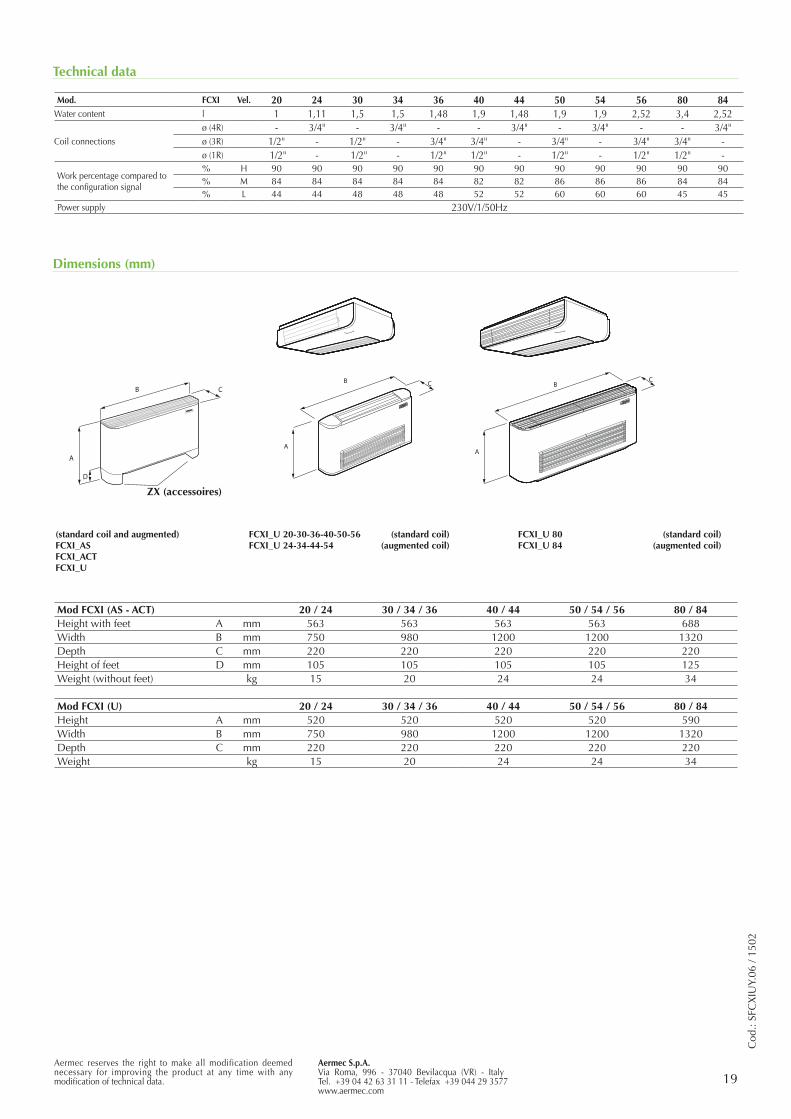
Dimensions (mm)
Mod. FCXI Vel. 20 24 30 34 36 40 44 50 54 56 80 84Water content l 1 1,11 1,5 1,5 1,48 1,9 1,48 1,9 1,9 2,52 3,4 2,52
Coil connectionsø (4R) - 3/4" - 3/4" - - 3/4" - 3/4" - - 3/4"ø (3R) 1/2" - 1/2" - 3/4" 3/4" - 3/4" - 3/4" 3/4" -ø (1R) 1/2" - 1/2" - 1/2" 1/2" - 1/2" - 1/2" 1/2" -
Work percentage compared to the configuration signal
% H 90 90 90 90 90 90 90 90 90 90 90 90% M 84 84 84 84 84 82 82 86 86 86 84 84% L 44 44 48 48 48 52 52 60 60 60 45 45
Power supply 230V/1/50Hz
A
B C
A
BC
B
A
C
D
Mod FCXI (AS - ACT) 20 / 24 30 / 34 / 36 40 / 44 50 / 54 / 56 80 / 84Height with feet A mm 563 563 563 563 688Width B mm 750 980 1200 1200 1320Depth C mm 220 220 220 220 220Height of feet D mm 105 105 105 105 125Weight (without feet) kg 15 20 24 24 34
Mod FCXI (U) 20 / 24 30 / 34 / 36 40 / 44 50 / 54 / 56 80 / 84Height A mm 520 520 520 520 590Width B mm 750 980 1200 1200 1320Depth C mm 220 220 220 220 220Weight kg 15 20 24 24 34
(standard coil and augmented)FCXI_ASFCXI_ACTFCXI_U
ZX (accessoires)
FCXI_U 20-30-36-40-50-56 (standard coil)FCXI_U 24-34-44-54 (augmented coil)
FCXI_U 80 (standard coil)FCXI_U 84 (augmented coil)
20
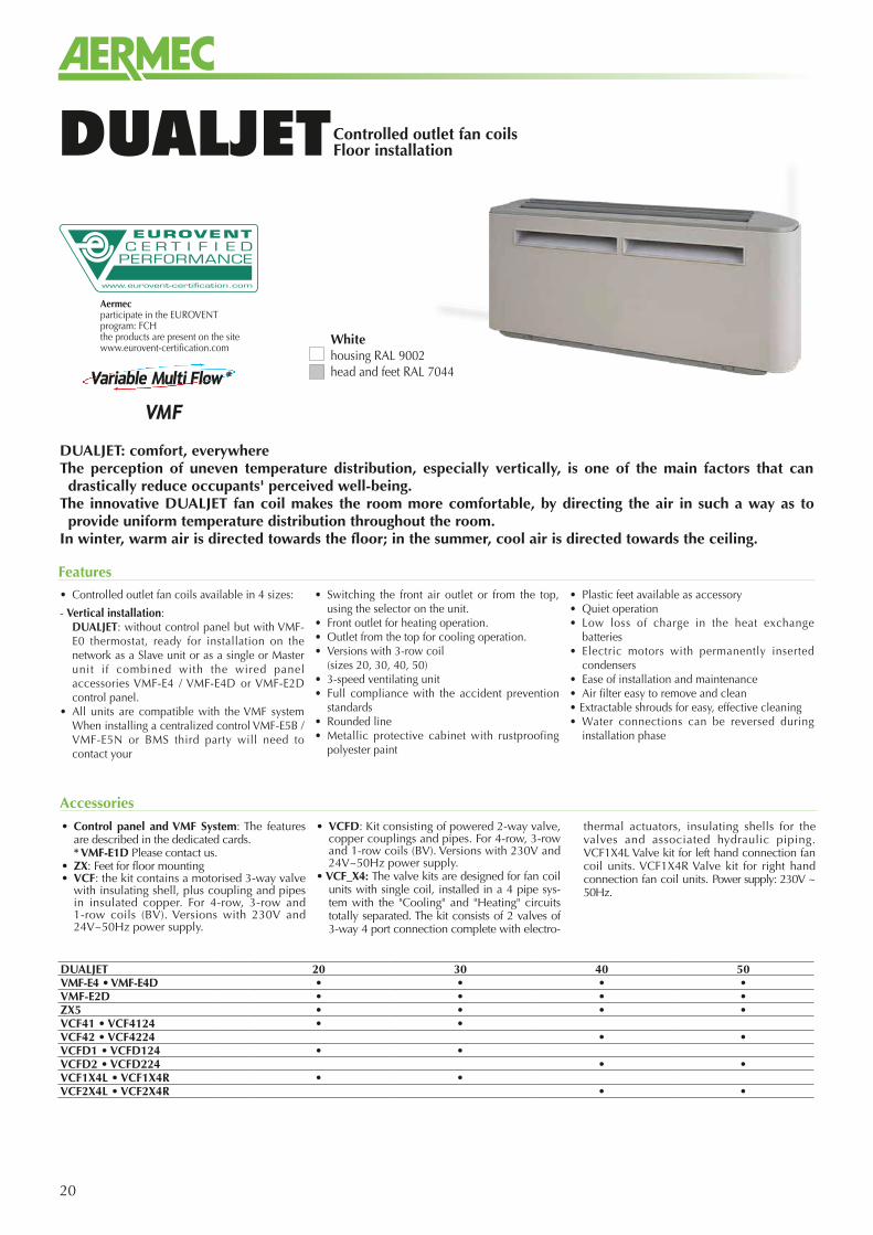
Controlled outlet fan coilsFloor installationDUALJET
• Controlled outlet fan coils available in 4 sizes:
- Vertical installation: DUALJET: without control panel but with VMF-
E0 thermostat, ready for installation on the network as a Slave unit or as a single or Master unit if combined with the wired panel accessories VMF-E4 / VMF-E4D or VMF-E2D control panel.
• All units are compatible with the VMF system When installing a centralized control VMF-E5B / VMF-E5N or BMS third party will need to contact your
• Switching the front air outlet or from the top, using the selector on the unit.
• Front outlet for heating operation. • Outlet from the top for cooling operation.• Versions with 3-row coil (sizes 20, 30, 40, 50)• 3-speed ventilating unit• Full compliance with the accident prevention
standards• Rounded line• Metallic protective cabinet with rustproofing
polyester paint
• Plastic feet available as accessory• Quiet operation• Low loss of charge in the heat exchange
batteries• Electric motors with permanently inserted
condensers• Ease of installation and maintenance• Air filter easy to remove and clean• Extractable shrouds for easy, effective cleaning• Water connections can be reversed during
installation phase
Features
DUALJET: comfort, everywhereThe perception of uneven temperature distribution, especially vertically, is one of the main factors that can drastically reduce occupants' perceived well-being.
The innovative DUALJET fan coil makes the room more comfortable, by directing the air in such a way as to provide uniform temperature distribution throughout the room.
In winter, warm air is directed towards the floor; in the summer, cool air is directed towards the ceiling.
• Control panel and VMF System: The features are described in the dedicated cards.
* VMF-E1D Please contact us.• ZX: Feet for floor mounting• VCF: the kit contains a motorised 3-way valve
with insulating shell, plus coupling and pipes in insulated copper. For 4-row, 3-row and 1-row coils (BV). Versions with 230V and 24V~50Hz power supply.
• VCFD: Kit consisting of powered 2-way valve, copper couplings and pipes. For 4-row, 3-row and 1-row coils (BV). Versions with 230V and 24V~50Hz power supply.
• VCF_X4: The valve kits are designed for fan coil units with single coil, installed in a 4 pipe sys-tem with the "Cooling" and "Heating" circuits totally separated. The kit consists of 2 valves of 3-way 4 port connection complete with electro-
thermal actuators, insulating shells for the valves and associated hydraulic piping. VCF1X4L Valve kit for left hand connection fan coil units. VCF1X4R Valve kit for right hand connection fan coil units. Power supply: 230V ~ 50Hz.
Accessories
Aermecparticipate in the EUROVENTprogram: FCHthe products are present on the sitewww.eurovent-certification.com
Whitehousing RAL 9002head and feet RAL 7044
DUALJET 20 30 40 50VMF-E4 • VMF-E4D • • • •VMF-E2D • • • •ZX5 • • • •VCF41 • VCF4124 • •VCF42 • VCF4224 • •VCFD1 • VCFD124 • •VCFD2 • VCFD224 • •VCF1X4L • VCF1X4R • •VCF2X4L • VCF2X4R • •
Aermec S.p.A.Via Roma, 996 - 37040 Bevilacqua (VR) - ItalyTel. 0442633111 - Telefax 044293577www.aermec.com
21Aermec reserves the right to make all modification deemed necessary for improving the product at any time with any modification of technical data.
Technical data
Cod
e: S
DJU
Y.04
/ 150
1
(1) Unit in standard configuration without accessories
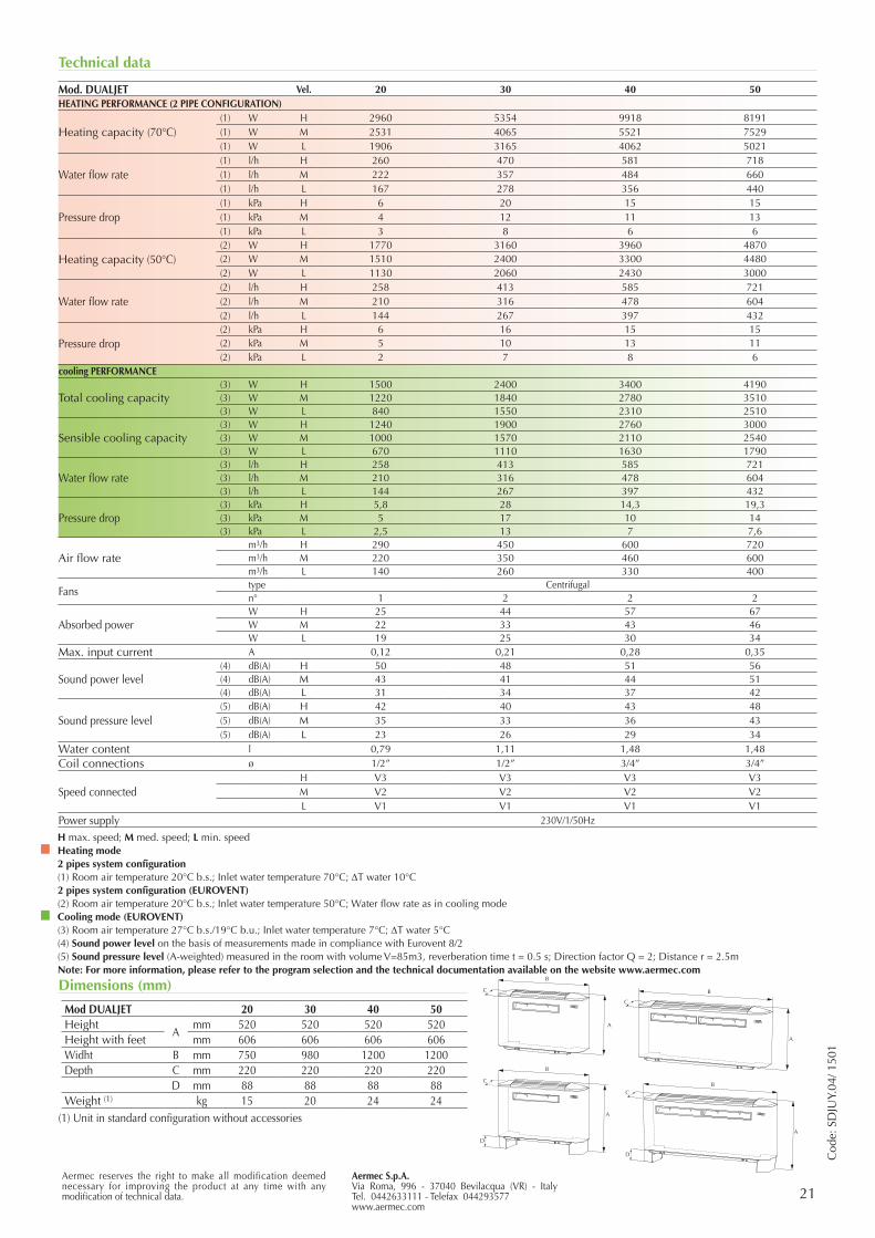
Mod. DUALJET Vel. 20 30 40 50HEATING PERFORMANCE (2 PIPE CONFIGURATION)
Heating capacity (70°C)(1) W H 2960 5354 9918 8191(1) W M 2531 4065 5521 7529(1) W L 1906 3165 4062 5021
Water flow rate(1) l/h H 260 470 581 718(1) l/h M 222 357 484 660(1) l/h L 167 278 356 440
Pressure drop(1) kPa H 6 20 15 15(1) kPa M 4 12 11 13(1) kPa L 3 8 6 6
Heating capacity (50°C)(2) W H 1770 3160 3960 4870(2) W M 1510 2400 3300 4480(2) W L 1130 2060 2430 3000
Water flow rate(2) l/h H 258 413 585 721(2) l/h M 210 316 478 604(2) l/h L 144 267 397 432
Pressure drop(2) kPa H 6 16 15 15(2) kPa M 5 10 13 11(2) kPa L 2 7 8 6
cooling PERFORMANCE
Total cooling capacity(3) W H 1500 2400 3400 4190(3) W M 1220 1840 2780 3510(3) W L 840 1550 2310 2510
Sensible cooling capacity(3) W H 1240 1900 2760 3000(3) W M 1000 1570 2110 2540(3) W L 670 1110 1630 1790
Water flow rate (3) l/h H 258 413 585 721(3) l/h M 210 316 478 604(3) l/h L 144 267 397 432
Pressure drop(3) kPa H 5,8 28 14,3 19,3(3) kPa M 5 17 10 14(3) kPa L 2,5 13 7 7,6
Air flow ratem3/h H 290 450 600 720m3/h M 220 350 460 600m3/h L 140 260 330 400
Fanstype Centrifugaln° 1 2 2 2
Absorbed powerW H 25 44 57 67W M 22 33 43 46W L 19 25 30 34
Max. input current A 0,12 0,21 0,28 0,35
Sound power level(4) dB(A) H 50 48 51 56(4) dB(A) M 43 41 44 51(4) dB(A) L 31 34 37 42
Sound pressure level(5) dB(A) H 42 40 43 48(5) dB(A) M 35 33 36 43(5) dB(A) L 23 26 29 34
Water content l 0,79 1,11 1,48 1,48Coil connections ø 1/2” 1/2” 3/4” 3/4”
Speed connectedH V3 V3 V3 V3M V2 V2 V2 V2L V1 V1 V1 V1
Power supply 230V/1/50Hz
H max. speed; M med. speed; L min. speedHeating mode2 pipes system configuration(1) Room air temperature 20°C b.s.; Inlet water temperature 70°C; DT water 10°C2 pipes system configuration (EUROVENT)(2) Room air temperature 20°C b.s.; Inlet water temperature 50°C; Water flow rate as in cooling modeCooling mode (EUROVENT)(3) Room air temperature 27°C b.s./19°C b.u.; Inlet water temperature 7°C; DT water 5°C(4) Sound power level on the basis of measurements made in compliance with Eurovent 8/2(5) Sound pressure level (A-weighted) measured in the room with volume V=85m3, reverberation time t = 0.5 s; Direction factor Q = 2; Distance r = 2.5mNote: For more information, please refer to the program selection and the technical documentation available on the website www.aermec.com
Dimensions (mm) C
B
D
A
B
C
A
B
A
D
C
A
B
C
Mod DUALJET 20 30 40 50Height
Amm 520 520 520 520
Height with feet mm 606 606 606 606Widht B mm 750 980 1200 1200Depth C mm 220 220 220 220
D mm 88 88 88 88Weight (1) kg 15 20 24 24
22
Aermecparticipate in the EUROVENT program: FCHthe products are present on the sitewww.eurovent-certification.com
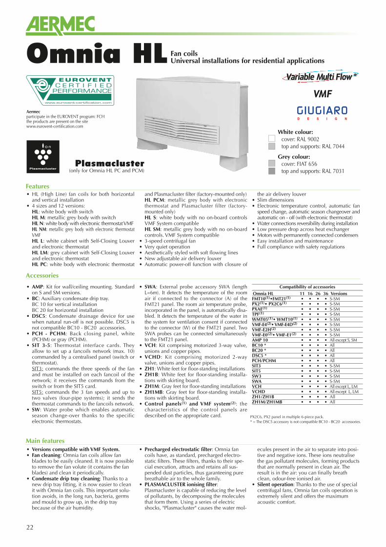
Fan coilsUniversal installations for residential applicationsOmnia HL
• HL (High Line) fan coils for both horizontal and vertical installation
• 4 sizes and 12 versions: HL: white body with switch HL M: metallic grey body with switch HL N: white body with electronic thermostat VMF HL NM: metallic grey body with electronic thermostat
VMF HL L: white cabinet with Self-Closing Louver
and electronic thermostat HL LM: grey cabinet with Self-Closing Louver
and electronic thermostat HL PC: white body with electronic thermostat
and Plasmacluster filter (factory-mounted only) HL PCM: metallic grey body with electronic
thermostat and Plasmacluster filter (factory-mounted only)
HL S: white body with no on-board controls VMF System compatible
HL SM: metallic grey body with no on-board controls. VMF System compatible
• 3-speed centrifugal fan• Very quiet operation• Aesthetically styled with soft flowing lines• New adjustable air delivery louver• Automatic power-off function with closure of
the air delivery louver• Slim dimensions• Electronic temperature control, automatic fan
speed change, automatic season changeover and automatic on - off (with electronic thermostat)
• Water connections reversibility during installation• Low pressure drop across heat exchanger• Motors with permanently connected condensers• Easy installation and maintenance• Full compliance with safety regulations
Features
Accessories
Plasmacluster(only for Omnia HL PC and PCM)
• Versions compatible with VMF System.• Fan cleaning: Omnia fan coils allow fan
blades to be easily cleaned. It is now possible to remove the fan volute (it contains the fan blades) and clean it periodically.
• Condensate drip tray cleaning: Thanks to a new drip tray fitting, it is now easier to clean it with Omnia fan coils. This important solu-tion avoids, in the long run, bacteria, germs and mould to grow up, in the drip tray because of the air humidity.
• Precharged electrostatic filter: Omnia fan coils have, as standard, precharged electro-static filters. These filters, thanks to their spe-cial execution, attracts and retains all sus-pended dust particles, thus garanteeing pure breathable air to the whole family.
• PLASMACLUSTER ionising filter: Plasmacluster is capable of reducing the level of pollutants, by decomposing the molecules that form them. Using a series of electric shocks, "Plasmacluster" causes the water mol-
ecules present in the air to separate into posi-tive and negative ions. These ions neutralise the gas pollutant molecules, forming products that are normally present in clean air. The result is in the air: you can finally breath clean, odour-free ionised air.
• Silent operation: Thanks to the use of special centrifugal fans, Omnia fan coils operation is extremely silent and offers the maximum acoustic comfort.
Main features
• AMP: Kit for wall/ceiling mounting. Standard on S and SM versions.
• BC: Auxiliary condensate drip tray. BC 10 for vertical installation BC 20 for horizontal installation• DSC5: Condensate drainage device for use
when natural run-off is not possible. DSC5 is not compatible BC10 - BC20 accessories.
• PCH - PCHM: Back closing panel, white (PCHM) or gray (PCHM).
• SIT 3-5: Thermostat interface cards. They allow to set up a fancoils network (max. 10) commanded by a centralised panel (switch or thermostat).
SIT3: commands the three speeds of the fan and must be installed on each fancoil of the network; it receives the commands from the switch or from the SIT5 card.
SIT5: commands the 3 fan speeds and up to two valves (four-pipe systems); it sends the thermostat commands to the fancoils network.
• SW: Water probe which enables automatic season change-over thanks to the specific electronic thermostats.
• SWA: External probe accessory SWA (length L=6m). It detects the temperature of the room air if connected to the connector (A) of the FMT21 panel. The room air temperature probe, incorporated in the panel, is automatically disa-bled. It detects the temperature of the water in the system for ventilation consent if connected to the connector (W) of the FMT21 panel. Two SWA probes can be connected simultaneously to the FMT21 panel.
• VCH: Kit comprising motorized 3-way valve, unions and copper pipes.
• VCHD: Kit comprising motorized 2-way valve, unions and copper pipes.
• ZH1: White feet for floor-standing installations• ZH1B: White feet for floor-standing installa-
tions with skirting board.• ZH1M: Gray feet for floor-standing installations• ZH1MB: Gray feet for floor-standing installa-
tions with skirting board.• Control panels(1) and VMF system(2): the
characteristics of the control panels are described on the appropriate card. PX2C6, PX2 panel in multiple 6-piece pack.
* = The DSC5 accessory is not compatible BC10 - BC20 accessories.
Compatibility of accessoriesOmnia HL 11 16 26 36 VersionsFMT10(1)•FMT21(1) • • • • S-SMPX2(1)• PX2C6(1) • • • • S-SMPXAE(1) • • • • S-SMTPF(1) • • • • S-SMWMT05(1)• WMT10(1) • • • • S-SMVMF-E4(2)• VMF-E4D(2) • • • • S-SMVMF-E2H(2) • • • • S-SMVMF-E0(2)• VMF-E1(2) • • • • S-SMAMP 10 • • • • All except S, SMBC10 * • • • • AllBC20 * • • • • AllDSC5 * • • • • AllPCH/PCHM • • • • AllSIT3 • • • • S-SMSIT5 • • • • S-SMSW3 • • • • S-SMSWA • • • • S-SMVCH • • • • All except L, LMVCHD • • • • All except L, LMZH1/ZH1B • • • • AllZH1M/ZH1MB • • • • All
White colour:cover: RAL 9002top and supports: RAL 7044
Grey colour:cover: FIAT 656top and supports: RAL 7031
Aermec S.p.A.Via Roma, 996 - 37040 Bevilacqua (VR) - ItalyTel. +39 04 42 63 31 11 - Telefax +39 044 29 3577www.aermec.com
23Aermec reserves the right to make all modification deemed necessary for improving the product at any time with any modification of technical data.
Cod
.: SO
HLU
Y.18
/ 15
02
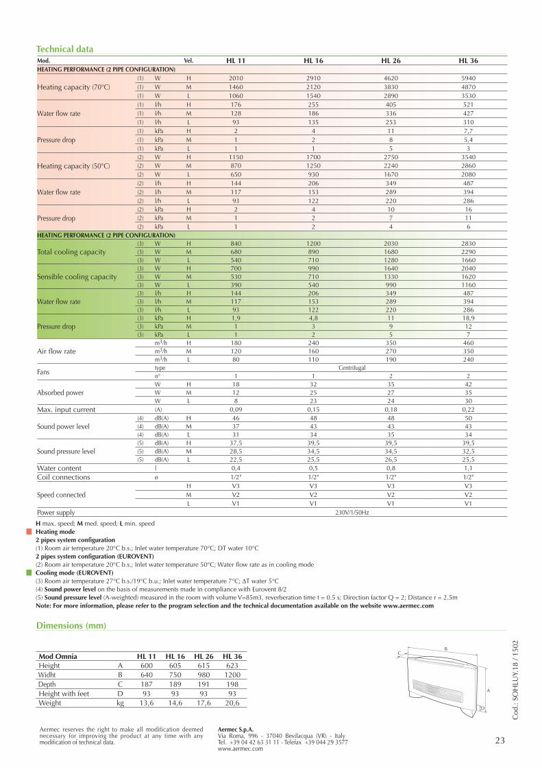
Technical data
Dimensions (mm)
Mod Omnia HL 11 HL 16 HL 26 HL 36Height A 600 605 615 623Widht B 640 750 980 1200Depth C 187 189 191 198Height with feet D 93 93 93 93Weight kg 13,6 14,6 17,6 20,6
Mod. Vel. HL 11 HL 16 HL 26 HL 36HEATING PERFORMANCE (2 PIPE CONFIGURATION)
Heating capacity (70°C)(1) W H 2010 2910 4620 5940(1) W M 1460 2120 3830 4870(1) W L 1060 1540 2890 3530
Water flow rate(1) l/h H 176 255 405 521(1) l/h M 128 186 336 427(1) l/h L 93 135 253 310
Pressure drop(1) kPa H 2 4 11 7,7(1) kPa M 1 2 8 5,4(1) kPa L 1 1 5 3
Heating capacity (50°C)(2) W H 1150 1700 2750 3540(2) W M 870 1250 2240 2860(2) W L 650 930 1670 2080
Water flow rate(2) l/h H 144 206 349 487(2) l/h M 117 153 289 394(2) l/h L 93 122 220 286
Pressure drop(2) kPa H 2 4 10 16(2) kPa M 1 2 7 11(2) kPa L 1 2 4 6
HEATING PERFORMANCE (2 PIPE CONFIGURATION)
Total cooling capacity(3) W H 840 1200 2030 2830(3) W M 680 890 1680 2290(3) W L 540 710 1280 1660
Sensible cooling capacity(3) W H 700 990 1640 2040(3) W M 530 710 1330 1620(3) W L 390 540 990 1160
Water flow rate (3) l/h H 144 206 349 487(3) l/h M 117 153 289 394(3) l/h L 93 122 220 286
Pressure drop(3) kPa H 1,9 4,8 11 18,9(3) kPa M 1 3 9 12(3) kPa L 1 2 5 7
Air flow ratem3/h H 180 240 350 460m3/h M 120 160 270 350m3/h L 80 110 190 240
Fanstype Centrifugaln° 1 1 2 2
Absorbed powerW H 18 32 35 42W M 12 25 27 35W L 8 23 24 30
Max. input current (A) 0,09 0,15 0,18 0,22
Sound power level(4) dB(A) H 46 48 48 50(4) dB(A) M 37 43 43 43(4) dB(A) L 31 34 35 34
Sound pressure level(5) dB(A) H 37,5 39,5 39,5 39,5(5) dB(A) M 28,5 34,5 34,5 32,5(5) dB(A) L 22,5 25,5 26,5 25,5
Water content l 0,4 0,5 0,8 1,1Coil connections ø 1/2" 1/2" 1/2" 1/2"
Speed connectedH V3 V3 V3 V3M V2 V2 V2 V2L V1 V1 V1 V1
Power supply 230V/1/50Hz
H max. speed; M med. speed; L min. speedHeating mode2 pipes system configuration(1) Room air temperature 20°C b.s.; Inlet water temperature 70°C; DT water 10°C2 pipes system configuration (EUROVENT)(2) Room air temperature 20°C b.s.; Inlet water temperature 50°C; Water flow rate as in cooling modeCooling mode (EUROVENT)(3) Room air temperature 27°C b.s./19°C b.u.; Inlet water temperature 7°C; DT water 5°C(4) Sound power level on the basis of measurements made in compliance with Eurovent 8/2(5) Sound pressure level (A-weighted) measured in the room with volume V=85m3, reverberation time t = 0.5 s; Direction factor Q = 2; Distance r = 2.5mNote: For more information, please refer to the program selection and the technical documentation available on the website www.aermec.com
24
Aermecparticipate in the EUROVENTprogram: FCHthe products are present on the sitewww.eurovent-certification.com
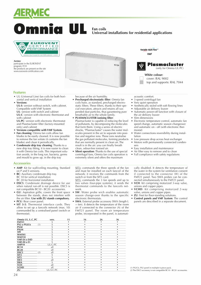
Fan coilsUniversal installations for residential applicationsOmnia UL
• AMP: Kit for wall/ceiling mounting. Standard on P and S versions.
• BC: Auxiliary condensate drip tray. BC 10 for vertical installation BC 20 for horizontal installation• DSC5: Condensate drainage device for use
when natural run-off is not possible. DSC5 is not compatible BC10 - BC20 accessories.
• GU: Aspiration grille, covers the front space between the stands, does not interfere with the air filter. Use with ZU stands compulsory.
• PCU: Rear cover panel.• SIT 3-5: Thermostat interface cards. They
allow to set up a fancoils network (max. 10) commanded by a centralised panel (switch or thermostat).
SIT3: commands the three speeds of the fan and must be installed on each fancoil of the network; it receives the commands from the switch or from the SIT5 card.
SIT5: commands the 3 fan speeds and up to two valves (four-pipe systems); it sends the thermostat commands to the fancoils net-work.
• SW: Water probe wich enables automatic season change-over thanks to the specific electronic thermostats.
• SWA: External probe accessory SWA (length L = 6m). It detects the temperature of the room air if connected to the connector (A) of the FMT21 panel. The room air temperature probe, incorporated in the panel, is automati-
cally disabled. It detects the temperature of the water in the system for ventilation consent if connected to the connector (W) of the FMT21 panel. Two SWA probes can be con-nected simultaneously to the FMT21 panel.
• VCH: Kit comprising motorized 3-way valve, unions and copper pipes.
• VCHD: Kit comprising motorized 2-way valve, unions and copper pipes.
• ZU: Feet for floor-standing solutions.• Control panels and VMF System: The control
panels are described in a separate document.
Accessories
• UL (Universal Line) fan coils for both hori-zontal and vertical installation
• Versions: UL-S: version without switch, with cabinet.
Compatible with VMF System UL: version with switch and cabinet UL-C: version with electronic thermostat and
with cabinet UL-PC: version with electronic thermostat
and Plasmacluster filter (factory-mounted only) and cabinet
• Versions compatible with VMF System.• Fan cleaning: Omnia fan coils allow fan
blades to be easily cleaned. It is now possible to remove the fan volute (it contains the fan blades) and clean it periodically.
• Condensate drip tray cleaning: Thanks to a new drip tray fitting, it is now easier to clean it with Omnia fan coils. This important solu-tion avoids, in the long run, bacteria, germs and mould to grow up, in the drip tray
because of the air humidity.• Precharged electrostatic filter: Omnia fan
coils have, as standard, precharged electro-static filters. These filters, thanks to their spe-cial execution, attracts and retains all sus-pended dust particles, thus garanteeing pure breathable air to the whole family.
• PLASMACLUSTER ionising filter: Plasmacluster is capable of reducing the level of pollutants, by decomposing the molecules that form them. Using a series of electric shocks, "Plasmacluster" causes the water mol-ecules present in the air to separate into posi-tive and negative ions. These ions neutralise the gas pollutant molecules, forming products that are normally present in clean air. The result is in the air: you can finally breath clean, odour-free ionised air.
• Silent operation: Thanks to the use of special centrifugal fans, Omnia fan coils operation is extremely silent and offers the maximum
acoustic comfort.• 3-speed centrifugal fan• Very quiet operation• Aesthetically styled with soft flowing lines• Adjustable air delivery louver• Automatic power-off function with closure of
the air delivery louver• Slim dimensions• Electronic temperature control, automatic fan
speed change, automatic season changeover and automatic on - off (with electronic ther-mostat)
• Water connections reversibility during instal-lation
• Low pressure drop across heat exchanger• Motors with permanently connected conden-
sers• Easy installation and maintenance• Air filter easy to remove and to clean• Full compliance with safety regulations
Features
Plasmacluster(only for Omnia UL PC)
(1) PX2C6, PX2 panel in multiple 6-piece pack.(2) The DSC5 accessory is not compatible BC10 - BC20 accessories.
White colour:cover: RAL 9002top and supports: RAL 7044
Omnia UL_S_C_PC vers. 11 16 26 36FMT21 S • • • •PX2 o PX2C6 (1) S • • • •PXAE S • • • •PXLM S • • • •TPF S • • • •WMT05 S • • • •WMT10 S • • • •VMF-E4 o E4D S • • • •VMF-E0 o E1 S • • • •AMP10 UL-C-PC • • • •BC10 all • • • •BC20 all • • • •DSC5 (2) all • • • •SIT3 S • • • •SIT5 S • • • •SW3 all • • • •SWA S • • • •VCH all • • • •VCHD all • • • •ZU UL-S-C-PC • • • •
Aermec S.p.A.Via Roma, 996 - 37040 Bevilacqua (VR) - ItalyTel. 0442633111 - Telefax 044293730www.aermec.com
25Aermec reserves the right to make all modification deemed necessary for improving the product at any time with any modification of technical data.
Cod
.: SO
ULU
Y.17
/ 150
2
Technical dataMod. Vel. UL11 UL16 UL26 UL36HEATING PERFORMANCE (2 PIPE CONFIGURATION)
Heating capacity (70°C)(1) W H 2010 2910 4620 5940(1) W M 1460 2120 3830 4870(1) W L 1060 1540 2890 3530
Water flow rate(1) l/h H 176 255 405 521(1) l/h M 128 186 336 427(1) l/h L 93 135 253 310
Pressure drop(1) kPa H 2 4 11 7,7(1) kPa M 1 2 8 5,4(1) kPa L 1 1 5 3
Heating capacity (50°C)(2) W H 1150 1700 2750 3540(2) W M 870 1250 2240 2860(2) W L 650 930 1670 2080
Water flow rate(2) l/h H 144 206 349 487(2) l/h M 117 153 289 394(2) l/h L 93 122 220 286
Pressure drop(2) kPa H 2 4 10 16(2) kPa M 1 2 7 11(2) kPa L 1 2 4 6
COOLING PERFORMANCE
Total cooling capacity(3) W H 840 1200 2030 2830(3) W M 680 890 1680 2290(3) W L 540 710 1280 1660
Sensible cooling capacity(3) W H 700 990 1640 2040(3) W M 530 710 1330 1620(3) W L 390 540 990 1160
Water flow rate (3) l/h H 144 206 349 487(3) l/h M 117 153 289 394(3) l/h L 93 122 220 286
Pressure drop(3) kPa H 1,9 4,8 11 18,9(3) kPa M 1 3 9 12(3) kPa L 1 2 5 7
Air flow ratem3/h H 180 240 350 460m3/h M 120 160 270 350m3/h L 80 110 190 240
Fanstype Centrifugaln° 1 1 2 2
Absorbed powerW H 18 32 35 42W M 12 25 27 35W L 8 23 24 30
Max. input current (A) 0,09 0,15 0,18 0,22
Sound power level(4) dB(A) H 46 48 48 50(4) dB(A) M 37 43 43 43(4) dB(A) L 31 34 35 34
Sound pressure level(5) dB(A) H 37,5 39,5 39,5 39,5(5) dB(A) M 28,5 34,5 34,5 32,5(5) dB(A) L 22,5 25,5 26,5 25,5
Water content l 0,4 0,5 0,8 1,1Coil connections ø 1/2" 1/2" 1/2" 1/2"
Speed connectedH V3 V3 V3 V3M V2 V2 V2 V2L V1 V1 V1 V1
Power supply 230V/1/50Hz
H max. speed; M med. speed; L min. speedHeating mode2 pipes system configuration(1) Room air temperature 20°C b.s.; Inlet water temperature 70°C; DT water 10°C2 pipes system configuration (EUROVENT)(2) Room air temperature 20°C b.s.; Inlet water temperature 50°C; Water flow rate as in cooling modeCooling mode (EUROVENT)(3) Room air temperature 27°C b.s./19°C b.u.; Inlet water temperature 7°C; DT water 5°C(4) Sound power level on the basis of measurements made in compliance with Eurovent 8/2(5) Sound pressure level (A-weighted) measured in the room with volume V=85m3, reverberation time t = 0.5 s; Direction factor Q = 2; Distance r = 2.5mNote: For more information, please refer to the program selection and the technical documentation available on the website www.aermec.com
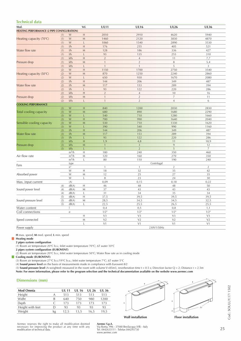
Mod Omnia UL 11 UL 16 UL 26 UL 36Height A 513 513 513 513Widht B 640 750 980 1200Depth C 173 173 173 173Height with feet D 93 93 93 93Weight kg 12,5 13,5 16,5 19,5
A
BC
A
D
ZU
BC
Wall installation Floor installation
Dimensions (mm)

26
Fan coils with radiant panel for residential use Ceiling or floor mounted
Omnia Radiant
Omnia Radiant and Omnia Radiant Plus Aermec innovative solutions In this particular worldwide market evolution, we are pleased to present to you OMNIA Radiant, which represents the innovation of the OMNIA AERMEC series, fan coils especially designed for residential comfort.
OMNIA Radiant inherits all the advantages of the OMNIA UL series, and is characterized by the introduction of the frontal plate for radiant heating.OMNIA Radiant Plus is provided with the DC Brushless electric engine, equipped with the latest Inverter technology, granting the highest energy efficiency and able to regulate the air flow through the continuous fan speed modula-tion. This allows to achieve up to 60% in energy saving when compared to the traditional On-Off fan system, in both air conditioning and heating.
OMNIA Radiant and Radiant Plus offer the fol-lowing advantages when compared to the tradi-tional systems:• the radiant plate combination – the finned
coil allows the best winter comfort with the lower energy consumption because it provi-des heating with lower water temperature: only 45°C against the about 65°C needed for the traditional radiator. This not only increases the comfort for the user, but also significantly increases the overall efficiency in case of heat pumps usage;
• the fan system allows to quickly reach the desired temperature, meeting the require-ment of a fast start-up;
• the unit can be combined other than the boiler, also to energy saving heat pumps: air to water, water to water and geothermic type;
• the electrostatic charge filter standard sup-plied, provides pure and clean air;
• during summer Omnia Radiant and Radiant Plus provide air conditioning and dehumidi-fication in a fast and efficient way in every room.
The four different working modes of Omnia Radiant annual functioning
Radiant: Heating through radiation, comfortable and noiseless, is granted by the radiant plate pla-ced on the front of the fan coil cover; if necessa-ry, the triple-fins delivery head can be closed to increases the heating of the plate, thus maximi-zing the radiant effect.
Radiant + Natural Convection With the triple-fins open, heating through natu-ral convection, obtained thanks to the bigger coil exchange surface, is added to the radiant heating.As for the radiant-only mode (see above), the fan groups are in off mode. This results in acoustic comfort and energy saving.
Radiant + Forced ConvectionThe electronic regulation, precise and reliable, continuously compares the effective indoor tem-perature with the desired temperature: whenever the difference between the two should prove to be too high (e.g. during the heating system start-up) the software will lead the fan system start-up. Start-up is fast and efficient and grants significant energy savings especially in rooms that are occa-sionally used.
Omnia Radiant during summer provides air conditioning and dehumidification:
Forced ConvectionDuring summer, Omnia Radiant and Radiant Plus provide air conditioning and dehumidifica-tion for each room of the house in a fast and effi-cient way. Efficiency and quietness benefit from the quality that has always characterized the Omnia series.
Features
Radiant
Radiant + Natural Convection
Radiant + Forced Convection
Forced Convection
Aermecparticipate in the EUROVENT program: FCUthe products are present on the sitewww.eurovent-certification.com
• LOW TEMPERATURE RADIATION*• VENTILATED HEATING• COOLING - DEHUMIDIFICATION• ENERGY SAVING • LOW OPERATING COST
* Radiant technology under licence
27
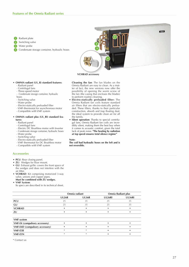
• OMNIA radiant (UL_R) standard features: - Radiant panel - Centrifugal fans - Three-speed motor - Condensate storage container, hydraulic
hoses - Switching valve - Water probe - Electro-statically preloaded filter - VMF-thermostat for asynchronous motor - Compatible with VMF system
• OMNIA radiant plus (UL_RI) standard fea-tures:
- Radiant panel - Centrifugal fans - Electric DC Brushless motor with Inverter - Condensate storage container, hydraulic hoses - Water probe - Switching valve - Electro-statically preloaded filter - VMF thermostat for DC Brushless motor - Compatible with VMF system
Cleaning the fan: The fan blades on the Omnia Radiant are easy to clean. As a mat-ter of fact, the new versions now offer the possibility of opening the worm screw of the fan (the casing that encloses the blades) to perform routine cleaning.
• Electro-statically preloaded filter: The Omnia Radiant fan coils feature standard air filters that are electro-statically preloa-ded. These filters, thanks to their particular construction, absorb and trap floating dust: the ideal system to provide clean air for all the family.
• Silent operation: Thanks to special centrifu-gal fans, Omnia Radiant fan coils are incre-dibly silent, making them the best buy when it comes to acoustic comfort, given the total lack of peak noise. "The heating by radiation at top speed ensures total silence regime”
Note:The coil had hydraulic hoses on the left and is not reversible.
Features of the Omnia Radiant series
Accessories
1
2
3
4
Radiant plate
Switching valve
Water probe
Condensate storage container, hydraulic hoses
1
2
3
4
• PCU: Rear closing panel.• ZU: Wedges for floor mount.• GU: Exhaust grille: covers the front space of
the wedges and does not interfere with the air filter.
• VCHRAD: Kit comprising motorized 3-way valve, unions and copper pipes.
Must be combined with ZU wedges.• VMF System: Its specs are described in its technical sheet.
Omnia radiant Omnia Radiant plusUL26R UL36R UL26RI UL36RI
PCU 25 35 25 35
GU 25 35 25 35
VCHRAD • • • •
ZU • • • •
VMF systemVMF-E4 (compulsory accessory) • • • •
VMF-E4D (compulsory accessory) • • • •
VMF-E5B * * • •
VMF-E5N * * • •
* Contact us
VCHRAD accessory
28
Technical Data
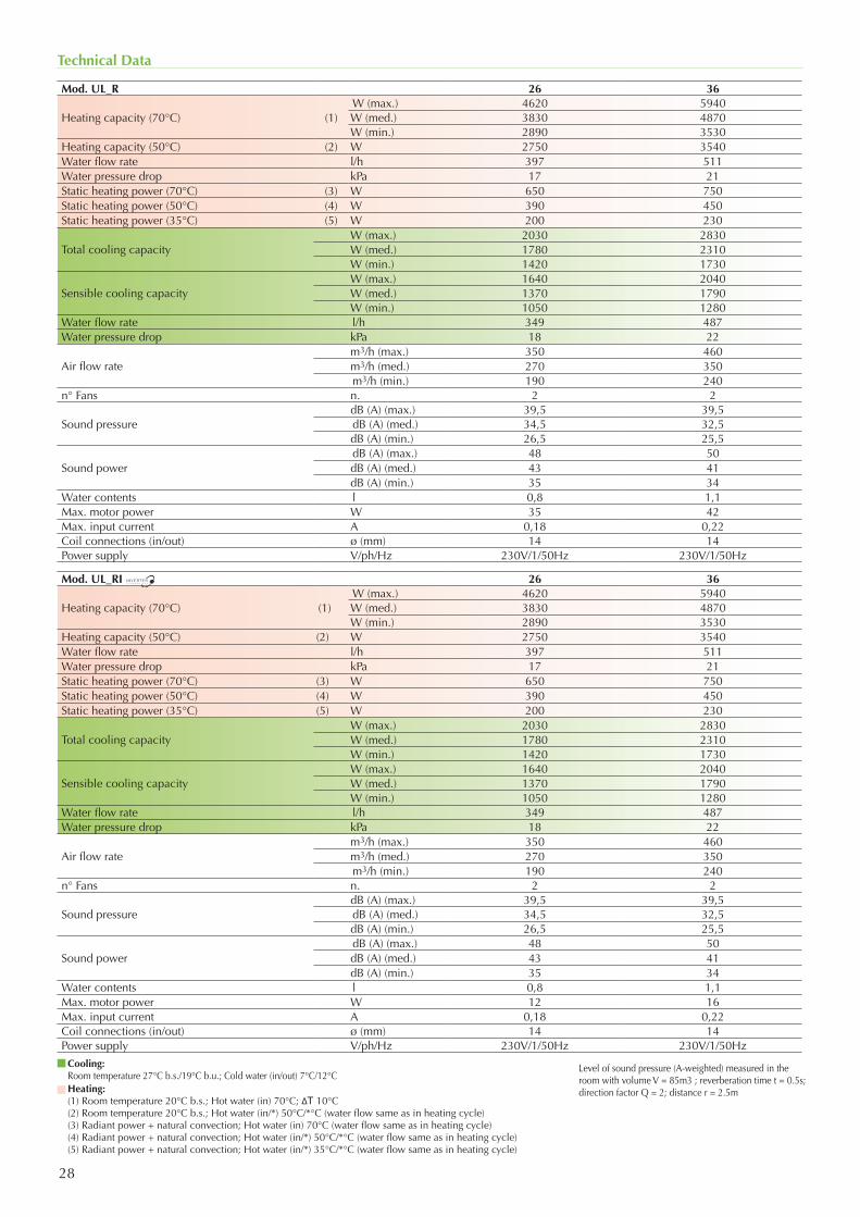
Cooling: Room temperature 27°C b.s./19°C b.u.; Cold water (in/out) 7°C/12°CHeating: (1) Room temperature 20°C b.s.; Hot water (in) 70°C; ΔT 10°C(2) Room temperature 20°C b.s.; Hot water (in/*) 50°C/*°C (water flow same as in heating cycle)(3) Radiant power + natural convection; Hot water (in) 70°C (water flow same as in heating cycle)(4) Radiant power + natural convection; Hot water (in/*) 50°C/*°C (water flow same as in heating cycle)(5) Radiant power + natural convection; Hot water (in/*) 35°C/*°C (water flow same as in heating cycle)
Mod. UL_R 26 36
Heating capacity (70°C) (1)W (max.) 4620 5940W (med.) 3830 4870W (min.) 2890 3530
Heating capacity (50°C) (2) W 2750 3540Water flow rate l/h 397 511Water pressure drop kPa 17 21Static heating power (70°C) (3) W 650 750Static heating power (50°C) (4) W 390 450Static heating power (35°C) (5) W 200 230
Total cooling capacityW (max.) 2030 2830W (med.) 1780 2310W (min.) 1420 1730
Sensible cooling capacityW (max.) 1640 2040W (med.) 1370 1790W (min.) 1050 1280
Water flow rate l/h 349 487Water pressure drop kPa 18 22
Air flow ratem3/h (max.) 350 460m3/h (med.) 270 350m3/h (min.) 190 240
n° Fans n. 2 2
Sound pressuredB (A) (max.) 39,5 39,5dB (A) (med.) 34,5 32,5dB (A) (min.) 26,5 25,5
Sound powerdB (A) (max.) 48 50dB (A) (med.) 43 41dB (A) (min.) 35 34
Water contents l 0,8 1,1Max. motor power W 35 42Max. input current A 0,18 0,22Coil connections (in/out) ø (mm) 14 14Power supply V/ph/Hz 230V/1/50Hz 230V/1/50Hz
Mod. UL_RI 26 36
Heating capacity (70°C) (1)W (max.) 4620 5940W (med.) 3830 4870W (min.) 2890 3530
Heating capacity (50°C) (2) W 2750 3540Water flow rate l/h 397 511Water pressure drop kPa 17 21Static heating power (70°C) (3) W 650 750Static heating power (50°C) (4) W 390 450Static heating power (35°C) (5) W 200 230
Total cooling capacityW (max.) 2030 2830W (med.) 1780 2310W (min.) 1420 1730
Sensible cooling capacityW (max.) 1640 2040W (med.) 1370 1790W (min.) 1050 1280
Water flow rate l/h 349 487Water pressure drop kPa 18 22
Air flow ratem3/h (max.) 350 460m3/h (med.) 270 350m3/h (min.) 190 240
n° Fans n. 2 2
Sound pressuredB (A) (max.) 39,5 39,5dB (A) (med.) 34,5 32,5dB (A) (min.) 26,5 25,5
Sound powerdB (A) (max.) 48 50dB (A) (med.) 43 41dB (A) (min.) 35 34
Water contents l 0,8 1,1Max. motor power W 12 16Max. input current A 0,18 0,22Coil connections (in/out) ø (mm) 14 14Power supply V/ph/Hz 230V/1/50Hz 230V/1/50Hz
Level of sound pressure (A-weighted) measured in the room with volume V = 85m3 ; reverberation time t = 0.5s; direction factor Q = 2; distance r = 2.5m
29Aermec S.p.A.Via Roma, 996 - 37040 Bevilacqua (VR) - ItaliaTel. 0442633111 - Telefax 044293577www.aermec.com
Aermec reserves the right to make all modification deemed necessary for improving the product at any time with any modification of technical data.
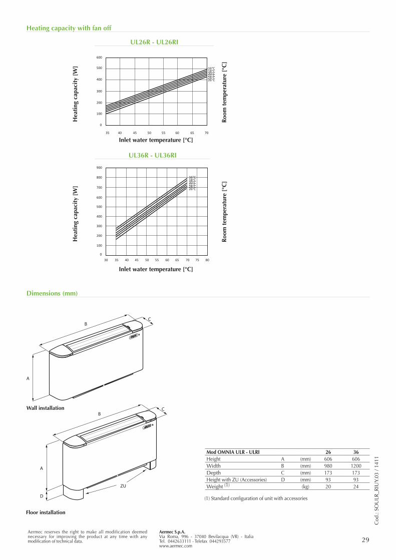
Heating capacity with fan off
Dimensions (mm)
A
BC
A
D
ZU
BC
Mod OMNIA ULR - ULRI 26 36Height A (mm) 606 606Width B (mm) 980 1200Depth C (mm) 173 173Height with ZU (Accessories) D (mm) 93 93Weight (1) (kg) 20 24
(1) Standard configuration of unit with accessories
Wall installation
Floor installation
Cod
.: SO
ULR
_RIU
Y.03
/ 14
11
UL26R - UL26RI
UL36R - UL36RI
Hea
ting
cap
acit
y [W
]H
eati
ng c
apac
ity
[W]
Roo
m t
empe
ratu
re [
°C]
Roo
m t
empe
ratu
re [
°C]
Inlet water temperature [°C]
Inlet water temperature [°C]
20°C18°C16°C
22°C24°C26°C
30 35 40 45 50 55 60 65 70 75 80
0
100
200
300
400
500
600
700
800
900
20°C18°C16°C
22°C24°C26°C
0
100
200
300
400
500
600
35 40 45 50 55 60 65 70
30
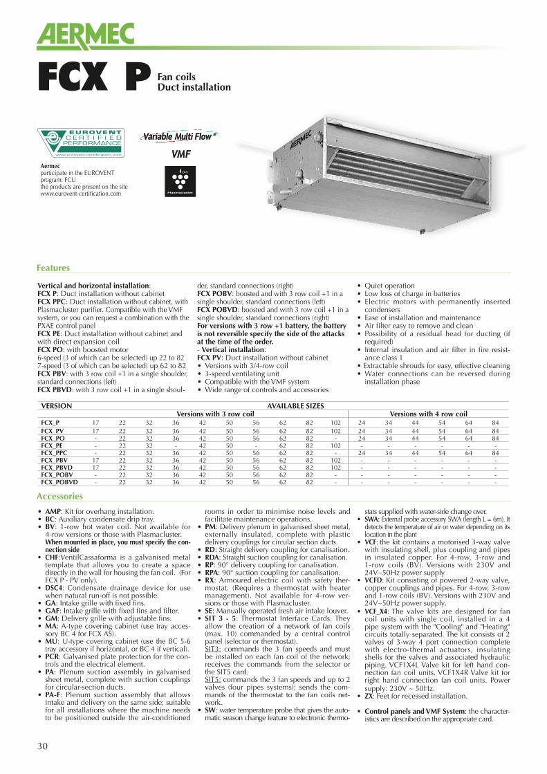
Fan coilsDuct installationFCX P
Vertical and horizontal installation:FCX P: Duct installation without cabinetFCX PPC: Duct installation without cabinet, with Plasmacluster purifier. Compatible with the VMF system, or you can request a combination with the PXAE control panelFCX PE: Duct installation without cabinet and with direct expansion coilFCX PO: with boosted motor6-speed (3 of which can be selected) up 22 to 82 7-speed (3 of which can be selected) up 62 to 82FCX PBV: with 3 row coil +1 in a single shoulder, standard connections (left)FCX PBVD: with 3 row coil +1 in a single shoul-
der, standard connections (right)FCX POBV: boosted and with 3 row coil +1 in a single shoulder, standard connections (left)FCX POBVD: boosted and with 3 row coil +1 in a single shoulder, standard connections (right)For versions with 3 row +1 battery, the battery is not reversible specify the side of the attacks at the time of the order. - Vertical installation:FCX PV: Duct installation without cabinet• Versions with 3/4-row coil• 3-speed ventilating unit• Compatible with the VMF system• Wide range of controls and accessories
• Quiet operation• Low loss of charge in batteries • Electric motors with permanently inserted
condensers• Ease of installation and maintenance• Air filter easy to remove and clean• Possibility of a residual head for ducting (if
required)• Internal insulation and air filter in fire resist-
ance class 1• Extractable shrouds for easy, effective cleaning• Water connections can be reversed during
installation phase
Features
• AMP: Kit for overhang installation.• BC: Auxiliary condensate drip tray.• BV: 1-row hot water coil. Not available for
4-row versions or those with Plasmacluster. When mounted in place, you must specify the con-
nection side• CHF:VentilCassaforma is a galvanised metal
template that allows you to create a space directly in the wall for housing the fan coil. (For FCX P - PV only).
• DSC4: Condensate drainage device for use when natural run-off is not possible.
• GA: Intake grille with fixed fins.• GAF: Intake grille with fixed fins and filter.• GM: Delivery grille with adjustable fins.• MA: A-type covering cabinet (use tray acces-
sory BC 4 for FCX AS).• MU: U-type covering cabinet (use the BC 5-6
tray accessory if horizontal, or BC 4 if vertical).• PCR: Galvanised plate protection for the con-
trols and the electrical element.• PA: Plenum suction assembly in galvanised
sheet metal, complete with suction couplings for circular-section ducts.
• PA-F: Plenum suction assembly that allows intake and delivery on the same side; suitable for all installations where the machine needs to be positioned outside the air-conditioned
rooms in order to minimise noise levels and facilitate maintenance operations.
• PM: Delivery plenum in galvanised sheet metal, externally insulated, complete with plastic delivery couplings for circular section ducts.
• RD: Straight delivery coupling for canalisation.• RDA: Straight suction coupling for canalisation.• RP: 90° delivery coupling for canalisation.• RPA: 90° suction coupling for canalisation.• RX: Armoured electric coil with safety ther-
mostat. (Requires a thermostat with heater management). Not available for 4-row ver-sions or those with Plasmacluster.
• SE: Manually operated fresh air intake louver.• SIT 3 - 5: Thermostat Interface Cards. They
allow the creation of a network of fan coils (max. 10) commanded by a central control panel (selector or thermostat).
SIT3: commands the 3 fan speeds and must be installed on each fan coil of the network; receives the commands from the selector or the SIT5 card.
SIT5: commands the 3 fan speeds and up to 2 valves (four pipes systems); sends the com-mands of the thermostat to the fan coils net-work.
• SW: water temperature probe that gives the auto-matic season change feature to electronic thermo-
stats supplied with water-side change over.• SWA: External probe accessory SWA (length L = 6m). It
detects the temperature of air or water depending on its location in the plant
• VCF: the kit contains a motorised 3-way valve with insulating shell, plus coupling and pipes in insulated copper. For 4-row, 3-row and 1-row coils (BV). Versions with 230V and 24V~50Hz power supply
• VCFD: Kit consisting of powered 2-way valve, copper couplings and pipes. For 4-row, 3-row and 1-row coils (BV). Versions with 230V and 24V~50Hz power supply.
• VCF_X4: The valve kits are designed for fan coil units with single coil, installed in a 4 pipe system with the "Cooling" and "Heating" circuits totally separated. The kit consists of 2 valves of 3-way 4 port connection complete with electro-thermal actuators, insulating shells for the valves and associated hydraulic piping. VCF1X4L Valve kit for left hand con-nection fan coil units. VCF1X4R Valve kit for right hand connection fan coil units. Power supply: 230V ~ 50Hz.
• ZX: Feet for recessed installation.
• Control panels and VMF System: the character-istics are described on the appropriate card.
Accessories
VERSION AVAILABLE SIZESVersions with 3 row coil Versions with 4 row coil
FCX_P 17 22 32 36 42 50 56 62 82 102 24 34 44 54 64 84FCX_PV 17 22 32 36 42 50 56 62 82 102 24 34 44 54 64 84FCX_PO - 22 32 36 42 50 56 62 82 - 24 34 44 54 64 84FCX_PE - 22 32 - 42 50 - 62 82 102 - - - - - -FCX_PPC - 22 32 36 42 50 56 62 82 - 24 34 44 54 64 84FCX_PBV 17 22 32 36 42 50 56 62 82 102 - - - - - -FCX_PBVD 17 22 32 36 42 50 56 62 82 102 - - - - - -FCX_POBV - 22 32 36 42 50 56 62 82 - - - - - - -FCX_POBVD - 22 32 36 42 50 56 62 82 - - - - - - -
Aermecparticipate in the EUROVENTprogram: FCUthe products are present on the sitewww.eurovent-certification.com
31
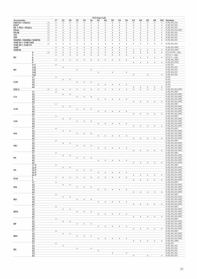
FCX Fan CoilAccessories 17 22 24 32 34 36 42 44 50 54 56 62 64 82 84 102 VersionsFMT10 • FMT21 (1) • • • • • • • • • • • • • • • • P-PE-PO-PVKTLP (1) • • • • • • • • • • • • • • • • P-PE-PO-PVPX • PX2 • PX2C6 (1) • • • • • • • • • • • • • • • • P-PE-PO-PVPXAE (1) • • • • • • • • • • • • • • • • P-PE-PO-PV-PPCPXAR (1) • • • • • • • • • • • • • • • • P-PE-PO-PVTF1 (1) • • • • • • • • • • • • • • • • P-PE-PO-PVTPF (1) • • • • • • • • • • • • • • • • P-PE-PO-PVWMT05 • WMT06 • WMT10 (1) • • • • • • • • • • • • • • • • P-PE-PO-PVVMF-E4 • VMF-E4D (1) • • • • • • • • • • • • • • • • P-PE-PO-PVVMF-E0 • VMF-E1AMP • • • • • • • • • • • P-PE-PO-PPCAMP20 • • • • • • • • • • • • • • • • P-PE-PO-PPC
BC
4 (2) • • • • • • • • • • • • • • • • FCX P-PV+ MA5 • • • • • • • • • • • FCX P + MU6 • • • • • FCX P + MU8 • • • • • • • • • • • P-PE-PO-PPC9 • • • • • P-PE-PO-PPC
BV
117 • P-PE-PV122 • P-PE-PO-PV132 • • P-PE-PO-PV142 • • • P-PE-PO-PV162 • • • P-PE-PO-PV
CHF
17 • P-PV22 • • P-PV32 • • • P-PV42 • • • • • P-PV62 • • • • • P-PV
DSC4 (3) • • • • • • • • • • • • • • • • P-PE-PO-PV-PPC
GA
17 • P-PE-PV-PPC22 • • P-PE-PO-PV-PPC32 • • • P-PE-PO-PV-PPC42 • • • • • P-PE-PO-PV-PPC62 • • • • • P-PE-PO-PV-PPC
GAF
17 • P-PE-PV-PPC22 • • P-PE-PO-PV-PPC32 • • • P-PE-PO-PV-PPC42 • • • • • P-PE-PO-PV-PPC62 • • • • • P-PE-PO-PV-PPC
GM
17 • P-PE-PV-PPC22 • • P-PE-PO-PV-PPC32 • • • P-PE-PO-PV-PPC42 • • • • • P-PE-PO-PV-PPC62 • • • • • P-PE-PO-PV-PPC
MA
17 • P-PE-PV-PPC22 • • P-PE-PO-PV-PPC32 • • • P-PE-PO-PV-PPC42 • • • • • P-PE-PO-PV-PPC62 • • • • • P-PE-PO-PV-PPC
MU
17 • P-PE-PV-PPC22 • • P-PE-PO-PV-PPC32 • • • P-PE-PO-PV-PPC42 • • • • • P-PE-PO-PV-PPC62 • • • • • P-PE-PO-PV-PPC
PA
17 • P-PE-PV-PPC22 • • P-PE-PO-PV-PPC32 • • • P-PE-PO-PV-PPC42 • • • • • P-PE-PO-PV-PPC62 • • • • • P-PE-PO-PV-PPC
PA
17 F • P-PE-PV-PPC22 F • • P-PE-PO-PV-PPC32 F • • • P-PE-PO-PV-PPC42 F • • • • • P-PE-PO-PV-PPC62 F • • • • • P-PE-PO-PV-PPC
PCR 1 • • • • • • • • • • • P-PE-PO-PV-PPC2 • • • • • P-PE-PO-PV-PPC
PM
17 • P-PE-PV-PPC22 • • P-PE-PO-PV-PPC32 • • • P-PE-PO-PV-PPC42 • • • • • P-PE-PO-PV-PPC62 • • • • • P-PE-PO-PV-PPC
RD
17 • P-PE-PV-PPC22 • • P-PE-PO-PV-PPC32 • • • P-PE-PO-PV-PPC42 • • • • • P-PE-PO-PV-PPC62 • • • • • P-PE-PO-PV-PPC
RDA
17 • P-PE-PV-PPC22 • • P-PE-PO-PV-PPC32 • • • P-PE-PO-PV-PPC42 • • • • • P-PE-PO-PV-PPC62 • • • • • P-PE-PO-PV-PPC
RP
17 • P-PE-PV-PPC22 • • P-PE-PO-PV-PPC32 • • • P-PE-PO-PV-PPC42 • • • • • P-PE-PO-PV-PPC62 • • • • • P-PE-PO-PV-PPC
RPA
17 • P-PE-PV-PPC22 • • P-PE-PO-PV-PPC32 • • • P-PE-PO-PV-PPC42 • • • • • P-PE-PO-PV-PPC62 • • • • • P-PE-PO-PPC
RX
17 • P-PE-PV22 • P-PE-PO-PV32 • • P-PE-PO-PV42 • P-PE-PO-PV52 • • P-PE-PO-PV62 • • • P-PE-PO-PV
32
Technical data
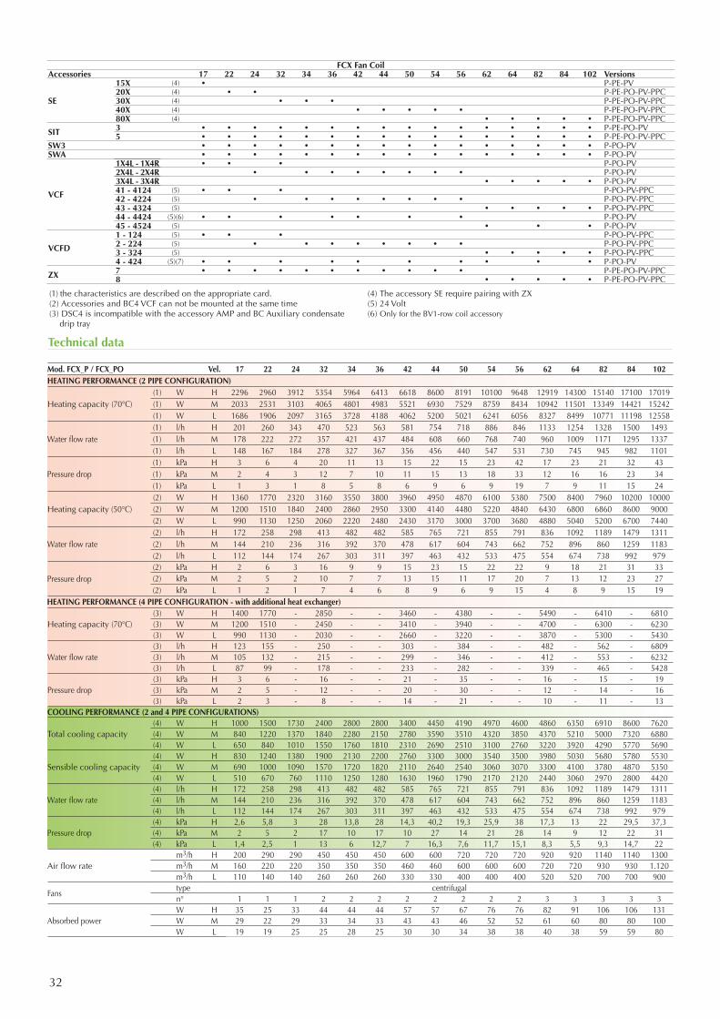
FCX Fan CoilAccessories 17 22 24 32 34 36 42 44 50 54 56 62 64 82 84 102 Versions
SE
15X (4) • P-PE-PV20X (4) • • P-PE-PO-PV-PPC30X (4) • • • P-PE-PO-PV-PPC40X (4) • • • • • P-PE-PO-PV-PPC80X (4) • • • • • P-PE-PO-PV-PPC
SIT 3 • • • • • • • • • • • • • • • • P-PE-PO-PV5 • • • • • • • • • • • • • • • • P-PE-PO-PV-PPC
SW3 • • • • • • • • • • • • • • • • P-PO-PVSWA • • • • • • • • • • • • • • • • P-PO-PV
VCF
1X4L - 1X4R • • • P-PO-PV2X4L - 2X4R • • • • • • • • P-PO-PV3X4L - 3X4R • • • • • P-PO-PV41 - 4124 (5) • • • P-PO-PV-PPC42 - 4224 (5) • • • • • • • • P-PO-PV-PPC43 - 4324 (5) • • • • • P-PO-PV-PPC44 - 4424 (5)(6) • • • • • • • P-PO-PV45 - 4524 (5) • • • P-PO-PV
VCFD
1 - 124 (5) • • • P-PO-PV-PPC2 - 224 (5) • • • • • • • • P-PO-PV-PPC3 - 324 (5) • • • • • P-PO-PV-PPC4 - 424 (5)(7) • • • • • • • • • • P-PO-PV
ZX 7 • • • • • • • • • • • P-PE-PO-PV-PPC8 • • • • • P-PE-PO-PV-PPC
(1) the characteristics are described on the appropriate card.(2) Accessories and BC4 VCF can not be mounted at the same time(3) DSC4 is incompatible with the accessory AMP and BC Auxiliary condensate
drip tray
(4) The accessory SE require pairing with ZX(5) 24 Volt(6) Only for the BV1-row coil accessory
Mod. FCX_P / FCX_PO Vel. 17 22 24 32 34 36 42 44 50 54 56 62 64 82 84 102HEATING PERFORMANCE (2 PIPE CONFIGURATION)
Heating capacity (70°C)(1) W H 2296 2960 3912 5354 5964 6413 6618 8600 8191 10100 9648 12919 14300 15140 17100 17019(1) W M 2033 2531 3103 4065 4801 4983 5521 6930 7529 8759 8434 10942 11501 13349 14421 15242(1) W L 1686 1906 2097 3165 3728 4188 4062 5200 5021 6241 6056 8327 8499 10771 11198 12558
Water flow rate(1) l/h H 201 260 343 470 523 563 581 754 718 886 846 1133 1254 1328 1500 1493(1) l/h M 178 222 272 357 421 437 484 608 660 768 740 960 1009 1171 1295 1337(1) l/h L 148 167 184 278 327 367 356 456 440 547 531 730 745 945 982 1101
Pressure drop(1) kPa H 3 6 4 20 11 13 15 22 15 23 42 17 23 21 32 43(1) kPa M 2 4 3 12 7 10 11 15 13 18 33 12 16 16 23 34(1) kPa L 1 3 1 8 5 8 6 9 6 9 19 7 9 11 15 24
Heating capacity (50°C)(2) W H 1360 1770 2320 3160 3550 3800 3960 4950 4870 6100 5380 7500 8400 7960 10200 10000(2) W M 1200 1510 1840 2400 2860 2950 3300 4140 4480 5220 4840 6430 6800 6860 8600 9000(2) W L 990 1130 1250 2060 2220 2480 2430 3170 3000 3700 3680 4880 5040 5200 6700 7440
Water flow rate(2) l/h H 172 258 298 413 482 482 585 765 721 855 791 836 1092 1189 1479 1311(2) l/h M 144 210 236 316 392 370 478 617 604 743 662 752 896 860 1259 1183(2) l/h L 112 144 174 267 303 311 397 463 432 533 475 554 674 738 992 979
Pressure drop(2) kPa H 2 6 3 16 9 9 15 23 15 22 22 9 18 21 31 33(2) kPa M 2 5 2 10 7 7 13 15 11 17 20 7 13 12 23 27(2) kPa L 1 2 1 7 4 6 8 9 6 9 15 4 8 9 15 19
HEATING PERFORMANCE (4 PIPE CONFIGURATION - with additional heat exchanger)
Heating capacity (70°C)(3) W H 1400 1770 - 2850 - - 3460 - 4380 - - 5490 - 6410 - 6810(3) W M 1200 1510 - 2450 - - 3410 - 3940 - - 4700 - 6300 - 6230(3) W L 990 1130 - 2030 - - 2660 - 3220 - - 3870 - 5300 - 5430
Water flow rate(3) l/h H 123 155 - 250 - - 303 - 384 - - 482 - 562 - 6809(3) l/h M 105 132 - 215 - - 299 - 346 - - 412 - 553 - 6232(3) l/h L 87 99 - 178 - - 233 - 282 - - 339 - 465 - 5428
Pressure drop(3) kPa H 3 6 - 16 - - 21 - 35 - - 16 - 15 - 19(3) kPa M 2 5 - 12 - - 20 - 30 - - 12 - 14 - 16(3) kPa L 2 3 - 8 - - 14 - 21 - - 10 - 11 - 13
COOLING PERFORMANCE (2 and 4 PIPE CONFIGURATIONS)
Total cooling capacity(4) W H 1000 1500 1730 2400 2800 2800 3400 4450 4190 4970 4600 4860 6350 6910 8600 7620(4) W M 840 1220 1370 1840 2280 2150 2780 3590 3510 4320 3850 4370 5210 5000 7320 6880(4) W L 650 840 1010 1550 1760 1810 2310 2690 2510 3100 2760 3220 3920 4290 5770 5690
Sensible cooling capacity(4) W H 830 1240 1380 1900 2130 2200 2760 3300 3000 3540 3500 3980 5030 5680 5780 5530(4) W M 690 1000 1090 1570 1720 1820 2110 2640 2540 3060 3070 3300 4100 3780 4870 5350(4) W L 510 670 760 1110 1250 1280 1630 1960 1790 2170 2120 2440 3060 2970 2800 4420
Water flow rate (4) l/h H 172 258 298 413 482 482 585 765 721 855 791 836 1092 1189 1479 1311(4) l/h M 144 210 236 316 392 370 478 617 604 743 662 752 896 860 1259 1183(4) l/h L 112 144 174 267 303 311 397 463 432 533 475 554 674 738 992 979
Pressure drop(4) kPa H 2,6 5,8 3 28 13,8 28 14,3 40,2 19,3 25,9 38 17,3 13 22 29,5 37,3(4) kPa M 2 5 2 17 10 17 10 27 14 21 28 14 9 12 22 31(4) kPa L 1,4 2,5 1 13 6 12,7 7 16,3 7,6 11,7 15,1 8,3 5,5 9,3 14,7 22
Air flow ratem3/h H 200 290 290 450 450 450 600 600 720 720 720 920 920 1140 1140 1300m3/h M 160 220 220 350 350 350 460 460 600 600 600 720 720 930 930 1.120m3/h L 110 140 140 260 260 260 330 330 400 400 400 520 520 700 700 900
Fanstype centrifugaln° 1 1 1 2 2 2 2 2 2 2 2 3 3 3 3 3
Absorbed powerW H 35 25 33 44 44 44 57 57 67 76 76 82 91 106 106 131W M 29 22 29 33 34 33 43 43 46 52 52 61 60 80 80 100W L 19 19 25 25 28 25 30 30 34 38 38 40 38 59 59 80
33Aermec S.p.A.Via Roma, 996 - 37040 Bevilacqua (VR) - ItaliaTel. 0442633111 - Telefax 044293577www.aermec.com
Aermec reserves the right to make all modification deemed necessary for improving the product at any time with any modification of technical data.
Cod
.: SF
CX
PUY.
16 /
1401
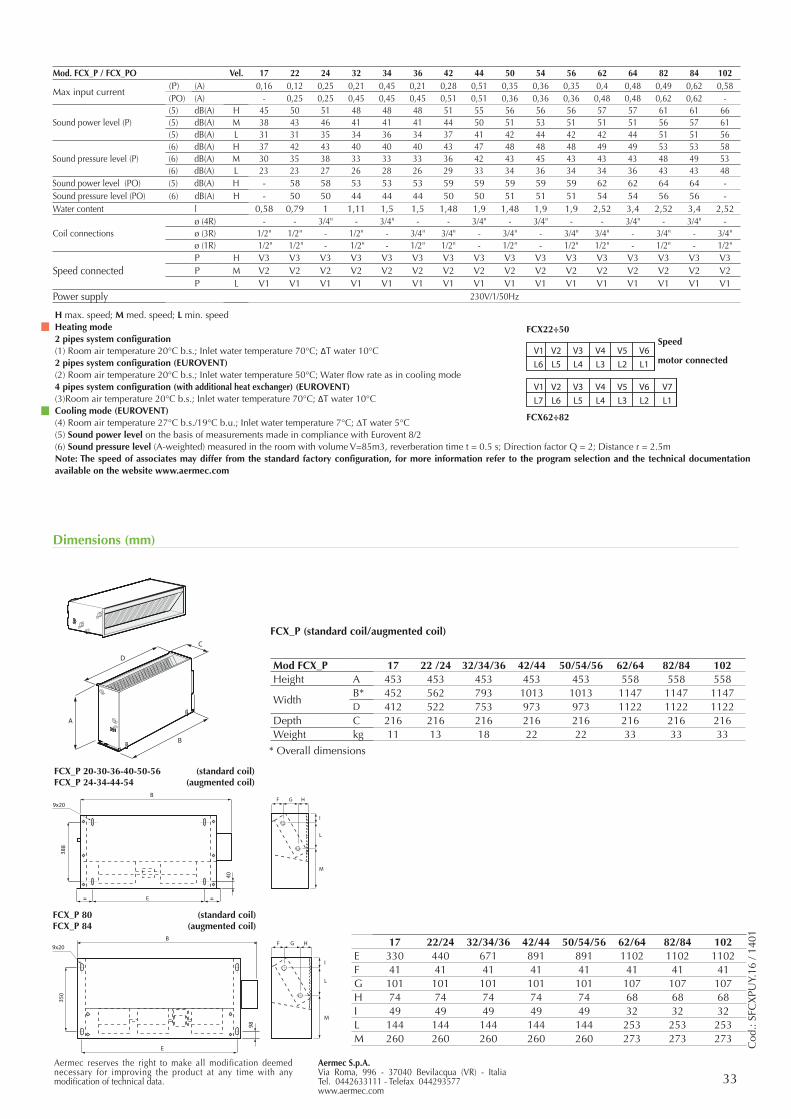
Mod. FCX_P / FCX_PO Vel. 17 22 24 32 34 36 42 44 50 54 56 62 64 82 84 102
Max input current(P) (A) 0,16 0,12 0,25 0,21 0,45 0,21 0,28 0,51 0,35 0,36 0,35 0,4 0,48 0,49 0,62 0,58(PO) (A) - 0,25 0,25 0,45 0,45 0,45 0,51 0,51 0,36 0,36 0,36 0,48 0,48 0,62 0,62 -
Sound power level (P)(5) dB(A) H 45 50 51 48 48 48 51 55 56 56 56 57 57 61 61 66(5) dB(A) M 38 43 46 41 41 41 44 50 51 53 51 51 51 56 57 61(5) dB(A) L 31 31 35 34 36 34 37 41 42 44 42 42 44 51 51 56
Sound pressure level (P)(6) dB(A) H 37 42 43 40 40 40 43 47 48 48 48 49 49 53 53 58(6) dB(A) M 30 35 38 33 33 33 36 42 43 45 43 43 43 48 49 53(6) dB(A) L 23 23 27 26 28 26 29 33 34 36 34 34 36 43 43 48
Sound power level (PO) (5) dB(A) H - 58 58 53 53 53 59 59 59 59 59 62 62 64 64 -Sound pressure level (PO) (6) dB(A) H - 50 50 44 44 44 50 50 51 51 51 54 54 56 56 -Water content l 0,58 0,79 1 1,11 1,5 1,5 1,48 1,9 1,48 1,9 1,9 2,52 3,4 2,52 3,4 2,52
Coil connectionsø (4R) - - 3/4" - 3/4" - - 3/4" - 3/4" - - 3/4" - 3/4" -ø (3R) 1/2" 1/2" - 1/2" - 3/4" 3/4" - 3/4" - 3/4" 3/4" - 3/4" - 3/4"ø (1R) 1/2" 1/2" - 1/2" - 1/2" 1/2" - 1/2" - 1/2" 1/2" - 1/2" - 1/2"
Speed connectedP H V3 V3 V3 V3 V3 V3 V3 V3 V3 V3 V3 V3 V3 V3 V3 V3P M V2 V2 V2 V2 V2 V2 V2 V2 V2 V2 V2 V2 V2 V2 V2 V2P L V1 V1 V1 V1 V1 V1 V1 V1 V1 V1 V1 V1 V1 V1 V1 V1
Power supply 230V/1/50Hz
H max. speed; M med. speed; L min. speedHeating mode2 pipes system configuration(1) Room air temperature 20°C b.s.; Inlet water temperature 70°C; ΔT water 10°C2 pipes system configuration (EUROVENT)(2) Room air temperature 20°C b.s.; Inlet water temperature 50°C; Water flow rate as in cooling mode4 pipes system configuration (with additional heat exchanger) (EUROVENT)(3)Room air temperature 20°C b.s.; Inlet water temperature 70°C; ΔT water 10°CCooling mode (EUROVENT)(4) Room air temperature 27°C b.s./19°C b.u.; Inlet water temperature 7°C; DT water 5°C(5) Sound power level on the basis of measurements made in compliance with Eurovent 8/2(6) Sound pressure level (A-weighted) measured in the room with volume V=85m3, reverberation time t = 0.5 s; Direction factor Q = 2; Distance r = 2.5mNote: The speed of associates may differ from the standard factory configuration, for more information refer to the program selection and the technical documentation available on the website www.aermec.com
L7 L6 L5 L4 L3 L2 L1V1 V2 V3 V4 V5 V6 V7
L6 L5 L4 L3 L2 L1 V1 V2 V3 V4 V5 V6
Speed
motor connected
FCX22÷50
FCX62÷82
17 22/24 32/34/36 42/44 50/54/56 62/64 82/84 102E 330 440 671 891 891 1102 1102 1102F 41 41 41 41 41 41 41 41G 101 101 101 101 101 107 107 107H 74 74 74 74 74 68 68 68I 49 49 49 49 49 32 32 32L 144 144 144 144 144 253 253 253M 260 260 260 260 260 273 273 273
Dimensions (mm)
A
D
B
C
FCX_P (standard coil/augmented coil)
* Overall dimensions
Mod FCX_P 17 22 /24 32/34/36 42/44 50/54/56 62/64 82/84 102Height A 453 453 453 453 453 558 558 558
WidthB* 452 562 793 1013 1013 1147 1147 1147D 412 522 753 973 973 1122 1122 1122
Depth C 216 216 216 216 216 216 216 216Weight kg 11 13 18 22 22 33 33 33
B
E
388
40
9x20
E
350
98
9x20B
F G H
I
L
M
F G H
I
L
M
FCX_P 20-30-36-40-50-56 (standard coil)FCX_P 24-34-44-54 (augmented coil)
FCX_P 80 (standard coil)FCX_P 84 (augmented coil)
34
Fan coils with Brushless Inverter motor (EC)In-duct installationFCXI P
Recessed fan coils with inverter technology, for heating, cooling and dehumidifying, specific to work in sensible environment.Equipped with inverter Brushless motor for an high effciency and a continuos air flow rate modulation in order to increased comfort and guarantee electric saving. The inverter motor allows a better air temperature regulation on based on the real indoor envirorement require-ments without temperature swinging. The FCXI P are the ideal solution for 2/4-pipe sys-tems and for tertiary and commercial installations.
Versions:FCXI P: wall/ceiling mounted without cabinetFCXI PBV: wall/ceiling mounted without cabinet with double circuit coil for 4-pipe system with standard connections (left)FCXI PBVD: wall/ceiling mounted without cabinet with double circuit coil for 4-pipe system with right connectionsThe hydraulic connections of the BV and BVD versions, up to size 56, are not reversible during installation. Specify the connection side when placing the order. • Brushless motor with 0-100% speed continuous variation to guarantee best performance at very low sound level• Centrifugal fan designed to guarantee continu-
ous modulation of the air flow rate and to increase comfort and electric saving.
• Unit with standard coil (20÷80) • Unit with larger coil (24÷84)• Low pressure drop• Air filter with easy extraction and cleaning• Removable augers for easy and effective clean-
ing• Reversibility of the hydraulic connections in the
installation phaseA specific wall-control range is available for the FCXI P. Choose between these panels for simple and complete regulation. Refer to the specific sheet for further details.
Features
• ELECTRIC SAVING EQUAL TO 50% COMPARED TO A FAN COIL WITH 3-SPEED MOTOR
• FULLY SILENT FUNCTIONING• FULL COMFORT: REDUCED TEMPERATURE AND RELATIVE HUMIDITY OSCILLATIONS
Accessories
• WMT21: Electronic thermostat with LCD display (wall installation).
• SWAI: Water temperature probe for WMT21 elec-tronic thermostat.
• VMF System: Find the features in the specific sheets.• AMP: Kit for wall/ceiling mounted installation.• BC: Auxiliary condensate drip tray.• BV: Hot water coil with one row. It is not available
for versions with 4 rows or with Plasmacluster. Specify the connection side in case of in-site
assembly.• PMZ: Plenum with motorised dampers (refer to the
specific sheet for further details).• CHF: The VentilCassaforma is a galvanised sheet
steel template, for P versions, which allows you to obtain a space for housing the fan coil, directly in the wall.
• DSC4: Device for draining condensate. • GA: Intake grid with fixed louvers.• GAF: Intake grid with fixed louvers with filter.
• GM: Flow grid with adjustable louvers.• MA: Protective cabinet, type A (use BC 4 tray
accessory).• MU: Protective cabinet, type U (use BC 5-6 tray
accessory if horizontal or use BC 4 if vertical).• PA: Galvanised sheet steel intake plenum
equipped with intake fittings for circular section ducts.
• PA-F: Intake plenum, which allows recovery and flow on the same side. It is suitable for all those installations outside air-conditioned rooms, in order to minimise noise and facilitate maintenance operations.
• PM: Galvanised sheet steel flow plenum, external-ly insulated, equipped with plastic flow fittings for ducts and circular sections.
• RD: Straight flow fitting for ducting.• RDA: Straight intake fitting for ducting.• RP: 90° flow fitting for ducting.• RPA: 90° intake fitting for ducting.• SE: External air damper with manual control.
• VCF: Kit made up of 3-way motorised valves with insulating shell, insulated copper fittings and pipes. For 4, 3, and 1-row coils (BV) Versions with 230V and 24V~50Hz power supply.
• VCFD: Kit composed of 2-way motorised valve and copper pipes and connections. For 4, 3, and 1-row coils (BV) Versions with 230V and 24V~50Hz power supply.
• Control panels and VMF System: Find the features in the specific sheets.
Aermecis participating in the EUROVENT Program : FCH/FCPHThe related products can be found at the website www.eurovent-certification.com
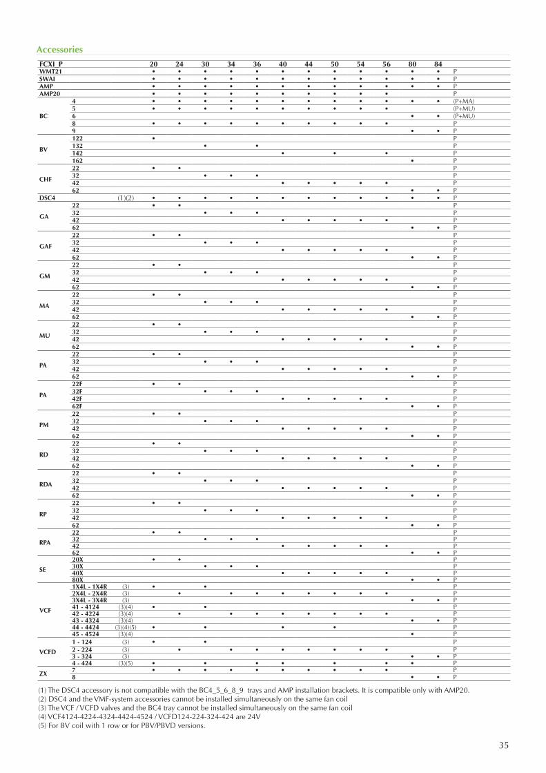
35
Accessories
(1) The DSC4 accessory is not compatible with the BC4_5_6_8_9 trays and AMP installation brackets. It is compatible only with AMP20.(2) DSC4 and the VMF-system accessories cannot be installed simultaneously on the same fan coil(3) The VCF / VCFD valves and the BC4 tray cannot be installed simultaneously on the same fan coil(4) VCF4124-4224-4324-4424-4524 / VCFD124-224-324-424 are 24V(5) For BV coil with 1 row or for PBV/PBVD versions.
FCXI_P 20 24 30 34 36 40 44 50 54 56 80 84WMT21 • • • • • • • • • • • • PSWAI • • • • • • • • • • • • PAMP • • • • • • • • • • • • PAMP20 • • • • • • • • • • P
BC
4 • • • • • • • • • • • • (P+MA)5 • • • • • • • • • • (P+MU)6 • • (P+MU)8 • • • • • • • • • • P9 • • P
BV
122 • P 132 • • P142 • • • P162 • P
CHF
22 • • P32 • • • P42 • • • • • P62 • • P
DSC4 (1)(2) • • • • • • • • • • • • P
GA
22 • • P32 • • • P42 • • • • • P62 • • P
GAF
22 • • P32 • • • P42 • • • • • P62 • • P
GM
22 • • P32 • • • P42 • • • • • P62 • • P
MA
22 • • P32 • • • P42 • • • • • P62 • • P
MU
22 • • P32 • • • P42 • • • • • P62 • • P
PA
22 • • P32 • • • P42 • • • • • P62 • • P
PA
22F • • P32F • • • P42F • • • • • P62F • • P
PM
22 • • P32 • • • P42 • • • • • P62 • • P
RD
22 • • P32 • • • P42 • • • • • P62 • • P
RDA
22 • • P32 • • • P42 • • • • • P62 • • P
RP
22 • • P32 • • • P42 • • • • • P62 • • P
RPA
22 • • P32 • • • P42 • • • • • P62 • • P
SE
20X • • P30X • • • P40X • • • • • P80X • • P
VCF
1X4L - 1X4R (3) • • P2X4L - 2X4R (3) • • • • • • • • P3X4L - 3X4R (3) • • P41 - 4124 (3)(4) • • P42 - 4224 (3)(4) • • • • • • • • P43 - 4324 (3)(4) • • P44 - 4424 (3)(4)(5) • • • • P45 - 4524 (3)(4) • P
VCFD
1 - 124 (3) • • P2 - 224 (3) • • • • • • • • P3 - 324 (3) • • P4 - 424 (3)(5) • • • • • • • P
ZX 7 • • • • • • • • • • P8 • • P
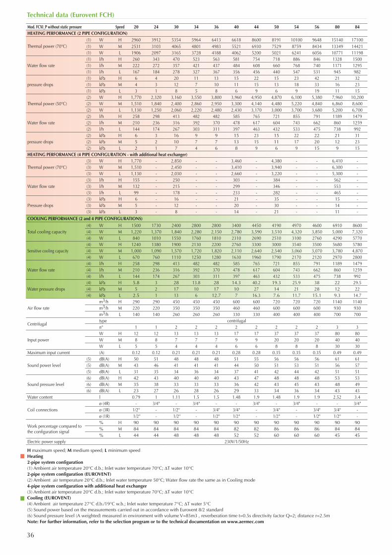
36
Technical data (Eurovent FCH)
Mod. FCXI_P without static pressure Speed 20 24 30 34 36 40 44 50 54 56 80 84HEATING PERFORMANCE (2 PIPE CONFIGURATION)
Thermal power (70°C)(1) W H 2960 3912 5354 5964 6413 6618 8600 8191 10100 9648 15140 17100(1) W M 2531 3103 4065 4801 4983 5521 6930 7529 8759 8434 13349 14421(1) W L 1906 2097 3165 3728 4188 4062 5200 5021 6241 6056 10771 11198
Water flow rate (1) l/h H 260 343 470 523 563 581 754 718 886 846 1328 1500(1) l/h M 222 272 357 421 437 484 608 660 768 740 1171 1295(1) l/h L 167 184 278 327 367 356 456 440 547 531 945 982
pressure drops(1) kPa H 6 4 20 11 13 15 22 15 23 42 21 32(1) kPa M 4 3 12 7 10 11 15 13 18 33 16 23(1) kPa L 3 1 8 5 8 6 9 6 9 19 11 15
Thermal power (50°C)(2) W H 1,770 2,320 3,160 3,550 3,800 3,960 4,950 4,870 6,100 5,380 7,960 10,200(2) W M 1,510 1,840 2,400 2,860 2,950 3,300 4,140 4,480 5,220 4,840 6,860 8,600(2) W L 1,130 1,250 2,060 2,220 2,480 2,430 3,170 3,000 3,700 3,680 5,200 6,700
Water flow rate(2) l/h H 258 298 413 482 482 585 765 721 855 791 1189 1479(2) l/h M 210 236 316 392 370 478 617 604 743 662 860 1259(2) l/h L 144 174 267 303 311 397 463 432 533 475 738 992
pressure drops(2) kPa H 6 3 16 9 9 15 23 15 22 22 21 31(2) kPa M 5 2 10 7 7 13 15 11 17 20 12 23(2) kPa L 2 1 7 4 6 8 9 6 9 15 9 15
HEATING PERFORMANCE (4 PIPE CONFIGURATION - with additional heat exchanger)
Thermal power (70°C)(3) W H 1,770 - 2,850 - - 3,460 - 4,380 - - 6,410 -(3) W M 1,510 - 2,450 - - 3,410 - 3,940 - - 6,300 -(3) W L 1,130 - 2,030 - - 2,660 - 3,220 - - 5,300 -
Water flow rate(3) l/h H 155 - 250 - - 303 - 384 - - 562 -(3) l/h M 132 - 215 - - 299 - 346 - - 553 -(3) l/h L 99 - 178 - - 233 - 282 - - 465 -
Pressure drops(3) kPa H 6 - 16 - - 21 - 35 - - 15 -(3) kPa M 5 - 12 - - 20 - 30 - - 14 -(3) kPa L 3 - 8 - - 14 - 21 - - 11 -
COOLING PERFORMANCE (2 and 4 PIPE CONFIGURATIONS)
Total cooling capacity(4) W H 1500 1730 2400 2800 2800 3400 4450 4190 4970 4600 6910 8600(4) W M 1,220 1,370 1,840 2,280 2,150 2,780 3,590 3,510 4,320 3,850 5,000 7,320(4) W L 840 1010 1550 1760 1810 2310 2690 2510 3100 2760 4290 5770
Sensitive cooling capacity(4) W H 1240 1380 1900 2130 2200 2760 3300 3000 3540 3500 5680 5780(4) W M 1,000 1,090 1,570 1,720 1,820 2,110 2,640 2,540 3,060 3,070 3,780 4,870(4) W L 670 760 1110 1250 1280 1630 1960 1790 2170 2120 2970 2800
Water flow rate(4) l/h H 258 298 413 482 482 585 765 721 855 791 1189 1479(4) l/h M 210 236 316 392 370 478 617 604 743 662 860 1259(4) l/h L 144 174 267 303 311 397 463 432 533 475 738 992
Water pressure drops(4) kPa H 5.8 3 28 13.8 28 14.3 40.2 19.3 25.9 38 22 29.5(4) kPa M 5 2 17 10 17 10 27 14 21 28 12 22(4) kPa L 2.5 1 13 6 12.7 7 16.3 7.6 11.7 15.1 9.3 14.7
Air flow ratem3/h H 290 290 450 450 450 600 600 720 720 720 1140 1140m3/h M 220 220 350 350 350 460 460 600 600 600 930 930m3/h L 140 140 260 260 260 330 330 400 400 400 700 700
Centrifugaltype centrifugaln° 1 1 2 2 2 2 2 2 2 2 3 3
Input powerW H 12 12 13 13 13 17 17 37 37 37 80 80W M 8 8 7 7 7 9 9 20 20 20 40 40W L 5 5 4 4 4 6 6 8 8 8 30 30
Maximum input current (A) 0.12 0.12 0.21 0.21 0.21 0.28 0.28 0.35 0.35 0.35 0.49 0.49
Sound power level(5) dB(A) H 50 51 48 48 48 51 55 56 56 56 61 61(5) dB(A) M 43 46 41 41 41 44 50 51 53 51 56 57(5) dB(A) L 31 35 34 36 34 37 41 42 44 42 51 51
Sound pressure level(6) dB(A) H 42 43 40 40 40 43 47 48 48 48 53 53(6) dB(A) M 35 38 33 33 33 36 42 43 45 43 48 49(6) dB(A) L 23 27 26 28 26 29 33 34 36 34 43 43
Water content l 0.79 1 1.11 1.5 1.5 1.48 1.9 1.48 1.9 1.9 2.52 3.4
Coil connectionsø (4R) - 3/4" - 3/4" - - 3/4" - 3/4" - - 3/4"ø (3R) 1/2" - 1/2" - 3/4" 3/4" - 3/4" - 3/4" 3/4" -ø (1R) 1/2" - 1/2" - 1/2" 1/2" - 1/2" - 1/2" 1/2" -
Work percentage compared to the configuration signal
% H 90 90 90 90 90 90 90 90 90 90 90 90% M 84 84 84 84 84 82 82 86 86 86 84 84% L 44 44 48 48 48 52 52 60 60 60 45 45
Electric power supply 230V/1/50Hz
H maximum speed; M medium speed; L minimum speedHeating2-pipe system configuration(1) Ambient air temperature 20°C d.b.; Inlet water temperature 70°C; DT water 10°C2-pipe system configuration (EUROVENT)(2) Ambient air temperature 20°C d.b.; Inlet water temperature 50°C; Water flow rate the same as in Cooling mode4-pipe system configuration with additional heat exchanger(3) Ambient air temperature 20°C d.b.; Inlet water temperature 70°C; DT water 10°CCooling (EUROVENT)(4) Ambient air temperature 27°C d.b./19°C w.b.; Inlet water temperature 7°C; DT water 5°C(5) Sound power based on the measurements carried out in accordance with Eurovent 8/2 standard(6) Sound pressure level (A weighted) measured in environment with volume V=85m3 , reverberation time t=0.5s directivity factor Q=2; distance r=2.5mNote: For further information, refer to the selection program or to the technical documentation on www.aermec.com
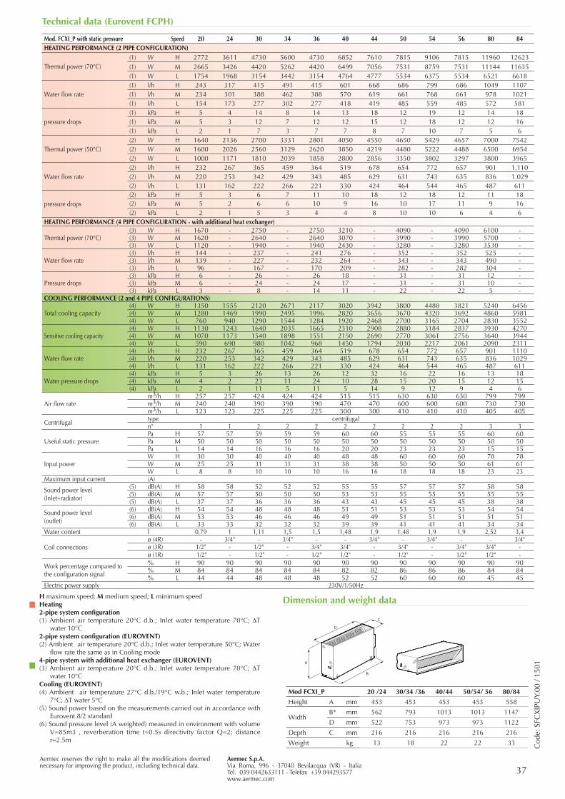
37Aermec S.p.A.Via Roma, 996 - 37040 Bevilacqua (VR) - ItaliaTel. 039 0442633111 - Telefax +39 044293577www.aermec.com
Aermec reserves the right to make all the modifications deemed necessary for improving the product, including technical data.
Technical data (Eurovent FCPH)
Cod
e: S
FCX
IPU
Y.00
/ 15
01
Dimension and weight data
Mod. FCXI_P with static pressure Speed 20 24 30 34 36 40 44 50 54 56 80 84HEATING PERFORMANCE (2 PIPE CONFIGURATION)
Thermal power (70°C)(1) W H 2772 3611 4730 5600 4730 6852 7610 7815 9106 7815 11960 12623(1) W M 2665 3426 4420 5262 4420 6499 7056 7531 8759 7531 11144 11635(1) W L 1754 1968 3154 3442 3154 4764 4777 5534 6375 5534 6521 6618
Water flow rate (1) l/h H 243 317 415 491 415 601 668 686 799 686 1049 1107(1) l/h M 234 301 388 462 388 570 619 661 768 661 978 1021(1) l/h L 154 173 277 302 277 418 419 485 559 485 572 581
pressure drops(1) kPa H 5 4 14 8 14 13 18 12 19 12 14 18(1) kPa M 5 3 12 7 12 12 15 12 18 12 12 16(1) kPa L 2 1 7 3 7 7 8 7 10 7 5 6
Thermal power (50°C)(2) W H 1640 2136 2700 3331 2801 4050 4550 4650 5429 4657 7000 7542(2) W M 1600 2026 2560 3129 2620 3850 4219 4480 5222 4488 6500 6954(2) W L 1000 1171 1810 2039 1858 2800 2856 3350 3802 3297 3800 3965
Water flow rate(2) l/h H 232 267 365 459 364 519 678 654 772 657 901 1.110(2) l/h M 220 253 342 429 343 485 629 631 743 635 836 1.029(2) l/h L 131 162 222 266 221 330 424 464 544 465 487 611
pressure drops(2) kPa H 5 3 6 7 11 10 18 12 18 12 11 18(2) kPa M 5 2 6 6 10 9 16 10 17 11 9 16(2) kPa L 2 1 5 3 4 4 8 10 10 6 4 6
HEATING PERFORMANCE (4 PIPE CONFIGURATION - with additional heat exchanger)
Thermal power (70°C)(3) W H 1670 - 2750 - 2750 3210 - 4090 - 4090 6100 -(3) W M 1620 - 2640 - 2640 3070 - 3990 - 3990 5700 -(3) W L 1120 - 1940 - 1940 2430 - 3280 - 3280 3530 -
Water flow rate(3) l/h H 144 - 237 - 241 276 - 352 - 352 525 -(3) l/h M 139 - 227 - 232 264 - 343 - 343 490 -(3) l/h L 96 - 167 - 170 209 - 282 - 282 304 -
Pressure drops(3) kPa H 6 - 26 - 26 18 - 31 - 31 12 -(3) kPa M 6 - 24 - 24 17 - 31 - 31 10 -(3) kPa L 3 - 8 - 14 11 - 22 - 22 5 -
COOLING PERFORMANCE (2 and 4 PIPE CONFIGURATIONS)
Total cooling capacity(4) W H 1350 1555 2120 2671 2117 3020 3942 3800 4488 3821 5240 6456(4) W M 1280 1469 1990 2495 1996 2820 3656 3670 4320 3692 4860 5981(4) W L 760 940 1290 1544 1284 1920 2468 2700 3165 2704 2830 3552
Sensitive cooling capacity(4) W H 1130 1243 1640 2035 1665 2310 2908 2880 3184 2837 3930 4270(4) W M 1070 1173 1540 1898 1551 2150 2690 2770 3061 2756 3640 3944(4) W L 590 690 980 1042 968 1450 1794 2030 2217 2061 2090 2311
Water flow rate(4) l/h H 232 267 365 459 364 519 678 654 772 657 901 1110(4) l/h M 220 253 342 429 343 485 629 631 743 635 836 1029(4) l/h L 131 162 222 266 221 330 424 464 544 465 487 611
Water pressure drops(4) kPa H 5 3 26 13 26 12 32 16 22 16 13 18(4) kPa M 4 2 23 11 24 10 28 15 20 15 12 15(4) kPa L 2 1 11 5 11 5 14 9 12 9 4 6
Air flow ratem3/h H 257 257 424 424 424 515 515 630 630 630 799 799m3/h M 240 240 390 390 390 470 470 600 600 600 730 730m3/h L 123 123 225 225 225 300 300 410 410 410 405 405
Centrifugal type centrifugaln° 1 1 2 2 2 2 2 2 2 2 3 3
Useful static pressurePa H 57 57 59 59 59 60 60 55 55 55 60 60Pa M 50 50 50 50 50 50 50 50 50 50 50 50Pa L 14 14 16 16 16 20 20 23 23 23 15 15
Input powerW H 30 30 40 40 40 48 48 60 60 60 78 78W M 25 25 31 31 31 38 38 50 50 50 61 61W L 8 8 10 10 10 16 16 18 18 18 23 23
Maximum input current (A)
Sound power level(Inlet+radiator)
(5) dB(A) H 58 58 52 52 52 55 55 57 57 57 58 58(5) dB(A) M 57 57 50 50 50 53 53 55 55 55 55 55(5) dB(A) L 37 37 36 36 36 43 43 45 45 45 38 38
Sound power level(outlet)
(6) dB(A) H 54 54 48 48 48 51 51 53 53 53 54 54(6) dB(A) M 53 53 46 46 46 49 49 51 51 51 51 51(6) dB(A) L 33 33 32 32 32 39 39 41 41 41 34 34
Water content l 0,79 1 1,11 1,5 1,5 1,48 1,9 1,48 1,9 1,9 2,52 3,4
Coil connectionsø (4R) - 3/4" - 3/4" - - 3/4" - 3/4" - - 3/4"ø (3R) 1/2" - 1/2" - 3/4" 3/4" - 3/4" - 3/4" 3/4" -ø (1R) 1/2" - 1/2" - 1/2" 1/2" - 1/2" - 1/2" 1/2" -
Work percentage compared to the configuration signal
% H 90 90 90 90 90 90 90 90 90 90 90 90% M 84 84 84 84 84 82 82 86 86 86 84 84% L 44 44 48 48 48 52 52 60 60 60 45 45
Electric power supply 230V/1/50Hz
A
D
B
C
A
D
B
C
Mod FCXI_P 20 /24 30/34 /36 40/44 50/54/ 56 80/84
Height A mm 453 453 453 453 558
WidthB* mm 562 793 1013 1013 1147
D mm 522 753 973 973 1122
Depth C mm 216 216 216 216 216
Weight kg 13 18 22 22 33
H maximum speed; M medium speed; L minimum speedHeating2-pipe system configuration(1) Ambient air temperature 20°C d.b.; Inlet water temperature 70°C; DT
water 10°C2-pipe system configuration (EUROVENT)(2) Ambient air temperature 20°C d.b.; Inlet water temperature 50°C; Water
flow rate the same as in Cooling mode4-pipe system with additional heat exchanger (EUROVENT)(3) Ambient air temperature 20°C d.b.; Inlet water temperature 70°C; DT
water 10°CCooling (EUROVENT)(4) Ambient air temperature 27°C d.b./19°C w.b.; Inlet water temperature
7°C; DT water 5°C(5) Sound power based on the measurements carried out in accordance with
Eurovent 8/2 standard(6) Sound pressure level (A weighted) measured in environment with volume
V=85m3 , reverberation time t=0.5s directivity factor Q=2; distance r=2.5m
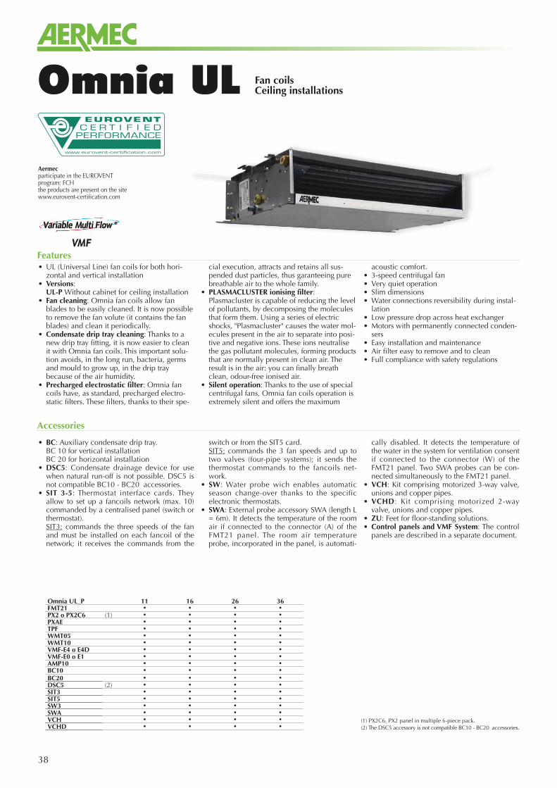
38
Aermecparticipate in the EUROVENTprogram: FCHthe products are present on the sitewww.eurovent-certification.com
Fan coilsCeiling installationsOmnia UL
• BC: Auxiliary condensate drip tray. BC 10 for vertical installation BC 20 for horizontal installation• DSC5: Condensate drainage device for use
when natural run-off is not possible. DSC5 is not compatible BC10 - BC20 accessories.
• SIT 3-5: Thermostat interface cards. They allow to set up a fancoils network (max. 10) commanded by a centralised panel (switch or thermostat).
SIT3: commands the three speeds of the fan and must be installed on each fancoil of the network; it receives the commands from the
switch or from the SIT5 card. SIT5: commands the 3 fan speeds and up to
two valves (four-pipe systems); it sends the thermostat commands to the fancoils net-work.
• SW: Water probe wich enables automatic season change-over thanks to the specific electronic thermostats.
• SWA: External probe accessory SWA (length L = 6m). It detects the temperature of the room air if connected to the connector (A) of the FMT21 panel. The room air temperature probe, incorporated in the panel, is automati-
cally disabled. It detects the temperature of the water in the system for ventilation consent if connected to the connector (W) of the FMT21 panel. Two SWA probes can be con-nected simultaneously to the FMT21 panel.
• VCH: Kit comprising motorized 3-way valve, unions and copper pipes.
• VCHD: Kit comprising motorized 2-way valve, unions and copper pipes.
• ZU: Feet for floor-standing solutions.• Control panels and VMF System: The control
panels are described in a separate document.
Accessories
• UL (Universal Line) fan coils for both hori-zontal and vertical installation
• Versions: UL-P Without cabinet for ceiling installation• Fan cleaning: Omnia fan coils allow fan
blades to be easily cleaned. It is now possible to remove the fan volute (it contains the fan blades) and clean it periodically.
• Condensate drip tray cleaning: Thanks to a new drip tray fitting, it is now easier to clean it with Omnia fan coils. This important solu-tion avoids, in the long run, bacteria, germs and mould to grow up, in the drip tray because of the air humidity.
• Precharged electrostatic filter: Omnia fan coils have, as standard, precharged electro-static filters. These filters, thanks to their spe-
cial execution, attracts and retains all sus-pended dust particles, thus garanteeing pure breathable air to the whole family.
• PLASMACLUSTER ionising filter: Plasmacluster is capable of reducing the level of pollutants, by decomposing the molecules that form them. Using a series of electric shocks, "Plasmacluster" causes the water mol-ecules present in the air to separate into posi-tive and negative ions. These ions neutralise the gas pollutant molecules, forming products that are normally present in clean air. The result is in the air: you can finally breath clean, odour-free ionised air.
• Silent operation: Thanks to the use of special centrifugal fans, Omnia fan coils operation is extremely silent and offers the maximum
acoustic comfort.• 3-speed centrifugal fan• Very quiet operation• Slim dimensions• Water connections reversibility during instal-
lation• Low pressure drop across heat exchanger• Motors with permanently connected conden-
sers• Easy installation and maintenance• Air filter easy to remove and to clean• Full compliance with safety regulations
Features
(1) PX2C6, PX2 panel in multiple 6-piece pack.(2) The DSC5 accessory is not compatible BC10 - BC20 accessories.
Omnia UL_P 11 16 26 36FMT21 • • • •PX2 o PX2C6 (1) • • • •PXAE • • • •TPF • • • •WMT05 • • • •WMT10 • • • •VMF-E4 o E4D • • • •VMF-E0 o E1 • • • •AMP10 • • • •BC10 • • • •BC20 • • • •DSC5 (2) • • • •SIT3 • • • •SIT5 • • • •SW3 • • • •SWA • • • •VCH • • • •VCHD • • • •
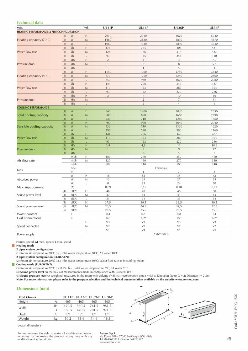
Aermec S.p.A.Via Roma, 996 - 37040 Bevilacqua (VR) - ItalyTel. 0442633111 - Telefax 044293577www.aermec.com
39Aermec reserves the right to make all modification deemed necessary for improving the product at any time with any modification of technical data.
Cod
.: SO
ULU
Y.00
/ 150
2
Technical dataMod. Vel. UL11P UL16P UL26P UL36PHEATING PERFORMANCE (2 PIPE CONFIGURATION)
Heating capacity (70°C)(1) W H 2010 2910 4620 5940(1) W M 1460 2120 3830 4870(1) W L 1060 1540 2890 3530
Water flow rate(1) l/h H 176 255 405 521(1) l/h M 128 186 336 427(1) l/h L 93 135 253 310
Pressure drop(1) kPa H 2 4 11 7,7(1) kPa M 1 2 8 5,4(1) kPa L 1 1 5 3
Heating capacity (50°C)(2) W H 1150 1700 2750 3540(2) W M 870 1250 2240 2860(2) W L 650 930 1670 2080
Water flow rate(2) l/h H 144 206 349 487(2) l/h M 117 153 289 394(2) l/h L 93 122 220 286
Pressure drop(2) kPa H 2 4 10 16(2) kPa M 1 2 7 11(2) kPa L 1 2 4 6
COOLING PERFORMANCE
Total cooling capacity(3) W H 840 1200 2030 2830(3) W M 680 890 1680 2290(3) W L 540 710 1280 1660
Sensible cooling capacity(3) W H 700 990 1640 2040(3) W M 530 710 1330 1620(3) W L 390 540 990 1160
Water flow rate (3) l/h H 144 206 349 487(3) l/h M 117 153 289 394(3) l/h L 93 122 220 286
Pressure drop(3) kPa H 1,9 4,8 11 18,9(3) kPa M 1 3 9 12(3) kPa L 1 2 5 7
Air flow ratem3/h H 180 240 350 460m3/h M 120 160 270 350m3/h L 80 110 190 240
Fanstype Centrifugaln° 1 1 2 2
Absorbed powerW H 18 32 35 42W M 12 25 27 35W L 8 23 24 30
Max. input current (A) 0,09 0,15 0,18 0,22
Sound power level(4) dB(A) H 46 48 48 50(4) dB(A) M 37 43 43 43(4) dB(A) L 31 34 35 34
Sound pressure level(5) dB(A) H 37,5 39,5 39,5 39,5(5) dB(A) M 28,5 34,5 34,5 32,5(5) dB(A) L 22,5 25,5 26,5 25,5
Water content l 0,4 0,5 0,8 1,1Coil connections ø 1/2" 1/2" 1/2" 1/2"
Speed connectedH V3 V3 V3 V3M V2 V2 V2 V2L V1 V1 V1 V1
Power supply 230V/1/50Hz
H max. speed; M med. speed; L min. speedHeating mode2 pipes system configuration(1) Room air temperature 20°C b.s.; Inlet water temperature 70°C; DT water 10°C2 pipes system configuration (EUROVENT)(2) Room air temperature 20°C b.s.; Inlet water temperature 50°C; Water flow rate as in cooling modeCooling mode (EUROVENT)(3) Room air temperature 27°C b.s./19°C b.u.; Inlet water temperature 7°C; DT water 5°C(4) Sound power level on the basis of measurements made in compliance with Eurovent 8/2(5) Sound pressure level (A-weighted) measured in the room with volume V=85m3, reverberation time t = 0.5 s; Direction factor Q = 2; Distance r = 2.5mNote: For more information, please refer to the program selection and the technical documentation available on the website www.aermec.com
Mod Omnia UL 11 UL 16 UL 26 UL 36Height A 513 513 513 513Widht B 640 750 980 1200Depth C 173 173 173 173Height with feet D 93 93 93 93Weight kg 12,5 13,5 16,5 19,5
Dimensions (mm)
Mod Omnia UL 11P UL 16P UL 26P UL 36PHeight A 465 465 465 465
Widht B* 420.5 530.5 761.5 981.5D 360.5 470.5 701.5 921.5
Depth C 171 171 171 171Weight kg 10.2 11.6 14.9 18.3
A
D
B
C
A
D
B
C
*overall dimensions
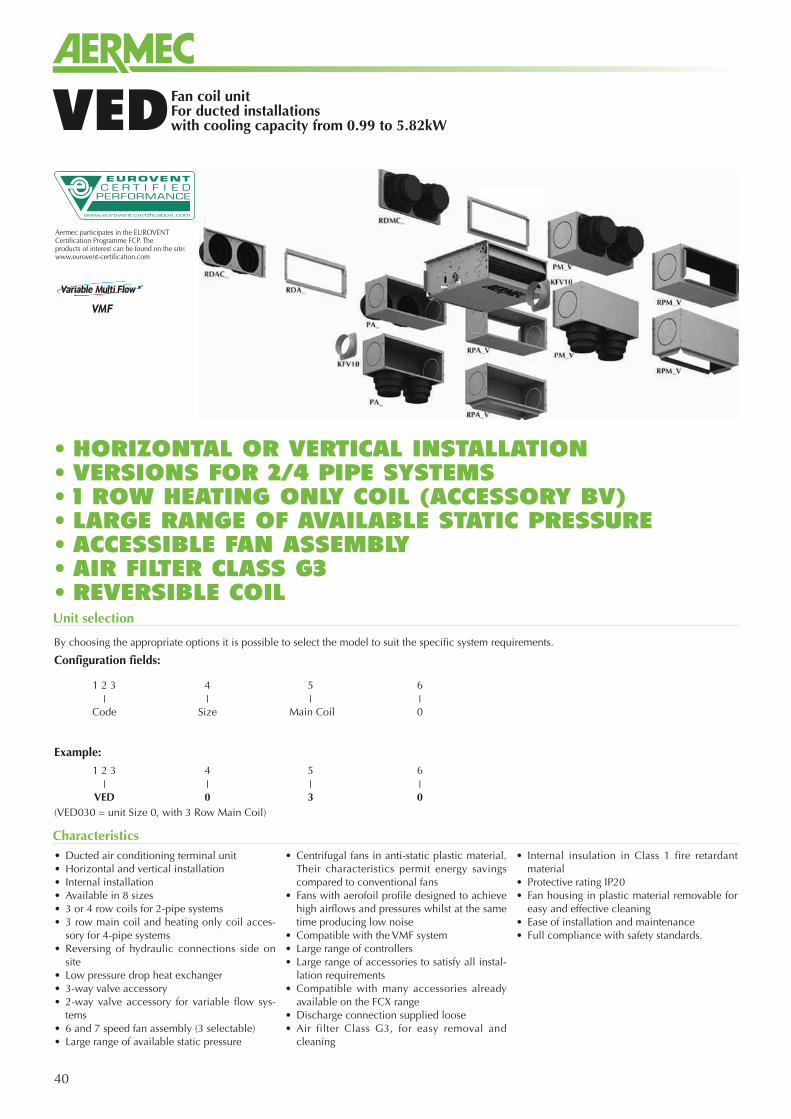
40
Fan coil unit For ducted installationswith cooling capacity from 0.99 to 5.82kWVED
• Ducted air conditioning terminal unit• Horizontal and vertical installation• Internal installation• Available in 8 sizes• 3 or 4 row coils for 2-pipe systems• 3 row main coil and heating only coil acces-
sory for 4-pipe systems • Reversing of hydraulic connections side on
site• Low pressure drop heat exchanger• 3-way valve accessory • 2-way valve accessory for variable flow sys-
tems• 6 and 7 speed fan assembly (3 selectable)• Large range of available static pressure
• Centrifugal fans in anti-static plastic material. Their characteristics permit energy savings compared to conventional fans
• Fans with aerofoil profile designed to achieve high airflows and pressures whilst at the same time producing low noise
• Compatible with the VMF system• Large range of controllers • Large range of accessories to satisfy all instal-
lation requirements• Compatible with many accessories already
available on the FCX range• Discharge connection supplied loose• Air filter Class G3, for easy removal and
cleaning
• Internal insulation in Class 1 fire retardant material
• Protective rating IP20• Fan housing in plastic material removable for
easy and effective cleaning• Ease of installation and maintenance• Full compliance with safety standards.
Characteristics
Aermec participates in the EUROVENT Certification Programme FCP. The products of interest can be found on the site: www.eurovent-certification.com
Unit selection
By choosing the appropriate options it is possible to select the model to suit the specific system requirements.
Configuration fields:
Example:
(VED030 = unit Size 0, with 3 Row Main Coil)
1 2 3 4 5 6❘ ❘ ❘ ❘
Code Size Main Coil 0
1 2 3 4 5 6❘ ❘ ❘ ❘
VED 0 3 0
• HORIZONTAL OR VERTICAL INSTALLATION• VERSIONS FOR 2/4 PIPE SYSTEMS • 1 ROW HEATING ONLY COIL (ACCESSORY BV)• LARGE RANGE OF AVAILABLE STATIC PRESSURE• ACCESSIBLE FAN ASSEMBLY• AIR FILTER CLASS G3• REVERSIBLE COIL
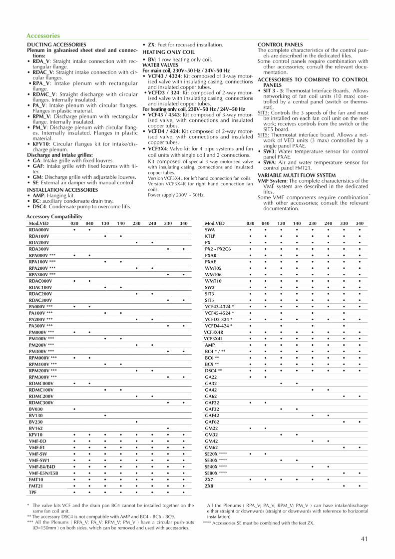
41
Accessories
* The valve kits VCF and the drain pan BC4 cannot be installed together on the same fan coil unit.
** The accessory DSC4 is not compatible with AMP and BC4 - BC6 - BC9.*** All the Plenums ( RPA_V; PA_V; RPM_V; PM_V ) have a circular push-outs
(Ø=150mm ) on both sides, which can be removed and used with accessories.
All the Plenums ( RPA_V; PA_V; RPM_V; PM_V ) can have intake/discharge either straight or downwards (straight or downwards with reference to horizontal installation).
**** Accessories SE must be combined with the feet ZX.
Mod.VED 030 040 130 140 230 240 330 340RDA000V • •RDA100V • •RDA200V • •RDA300V • •RPA000V *** • •RPA100V *** • •RPA200V *** • •RPA300V *** • •RDAC000V • •RDAC100V • •RDAC200V • •RDAC300V • •PA000V *** • •PA100V *** • •PA200V *** • •PA300V *** • •PM000V *** • •PM100V *** • •PM200V *** • •PM300V *** • •RPM000V *** • •RPM100V *** • •RPM200V *** • •RPM300V *** • •RDMC000V • •RDMC100V • •RDMC200V • •RDMC300V • •BV030 •BV130 •BV230 •BV162 •KFV10 • • • • • • • •VMF-EO • • • • • • • •VMF-E1 • • • • • • • •VMF-SW • • • • • • • •VMF-SW1 • • • • • • • •VMF-E4/E4D • • • • • • • •VMF-E5N/E5B • • • • • • • •FMT10 • • • • • • • •FMT21 • • • • • • • •TPF • • • • • • • •
Mod.VED 030 040 130 140 230 240 330 340SWA • • • • • • • •KTLP • • • • • • • •PX • • • • • • • •PX2 - PX2C6 • • • • • • • •PXAR • • • • • • • •PXAE • • • • • • • •WMT05 • • • • • • • •WMT06 • • • • • • • •WMT10 • • • • • • • •SW3 • • • • • • • •SIT3 • • • • • • • •SIT5 • • • • • • • •VCF43-4324 * • • • • • • • •VCF45-4524 * • • • •VCFD3-324 * • • • • • • • •VCFD4-424 * • • • •VCF3X4R • • • • • • • •VCF3X4L • • • • • • • •AMP • • • • • • • •BC4 * / ** • • • • • • • •BC6 ** • • • • • • • •BC9 ** • • • • • • • •DSC4 ** • • • • • • • •GA22 • •GA32 • •GA42 • •GA62 • •GAF22 • •GAF32 • •GAF42 • •GAF62 • •GM22 • •GM32 • •GM42 • •GM62 • •SE20X **** • •SE30X **** • •SE40X **** • •SE80X **** • •ZX7 • • • • • •ZX8 • •
Compatibilità accessori
DUCTING ACCESSORIES Plenum in galvanised sheet steel and connec-
tions:• RDA_V: Straight intake connection with rec-
tangular flange.• RDAC_V: Straight intake connection with cir-
cular flanges. • RPA_V: Intake plenum with rectangular
flange.• RDMC_V: Straight discharge with circular
flanges. Internally insulated.• PA_V: Intake plenum with circular flanges.
Flanges in plastic material.• RPM_V: Discharge plenum with rectangular
flange. Internally insulated.• PM_V: Discharge plenum with circular flang-
es. Internally insulated. Flanges in plastic material.
• KFV10: Circular flanges kit for intake/dis-charge plenum.
Discharge and intake grilles:• GA: Intake grille with fixed louvres.• GAF: Intake grille with fixed louvres with fil-
ter.• GM: Discharge grille with adjustable louvres.• SE: External air damper with manual control.INSTALLATION ACCESSORIES• AMP: Hanging kit.• BC: auxiliary condensate drain tray.• DSC4: Condensate pump to overcome lifts.
• ZX: Feet for recessed installation. HEATING ONLY COIL• BV: 1 row heating only coil. WATER VALVESFor main coil, 230V~50 Hz / 24V~50 Hz• VCF43 / 4324: Kit composed of 3-way motor-
ised valve with insulating casing, connections and insulated copper tubes.
• VCFD3 / 324: Kit composed of 2-way motor-ised valve with insulating casing, connections and insulated copper tubes.
For heating only coil, 230V~50 Hz / 24V~50 Hz• VCF45 / 4543: Kit composed of 3-way motor-
ised valve, with connections and insulated copper tubes.
• VCFD4 / 424: Kit composed of 2-way motor-ised valve, with connections and insulated copper tubes.
• VCF3X4: Valve kit for 4 pipe systems and fan coil units with single coil and 2 connections.
Kit composed of special 3 way motorised valve with insulating casing, connections and insulated copper tubes.
Version VCF3X4L for left hand connection fan coils. Version VCF3X4R for right hand connection fan
coils. Power supply 230V ~ 50Hz.
CONTROL PANELSThe complete characteristics of the control pan-
els are described in the dedicated files.Some control panels require combination with
other accessories; consult the relevant docu-mentation.
ACCESSORIES TO COMBINE TO CONTROL PANELS
• SIT 3 - 5: Thermostat Interface Boards. Allows networking of fan coil units (10 max) con-trolled by a central panel (switch or thermo-stat).
SIT3: Controls the 3 speeds of the fan and must be installed on each fan coil unit on the net-work; receives controls from the switch or the SIT5 board.
SIT5: Thermostat interface board. Allows a net-work of VED units (3 max) controlled by a single panel PXAE.
• SW3: Water temperature sensor for control panel PXAE.
• SWA: Air and water temperature sensor for control panel FMT21.
VARIABLE MULTI FLOW SYSTEMVMF System: The complete characteristics of the
VMF system are described in the dedicated files.
Some VMF components require combination with other accessories; consult the relevant documentation.
Accessory Compatibility
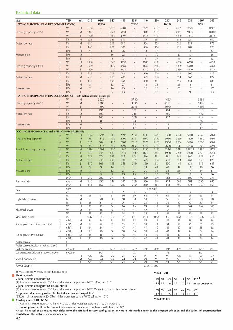
42
Technical data
H max. speed; M med. speed; L min. speedHeating mode2 pipes system configuration(1) Room air temperature 20°C b.s.; Inlet water temperature 70°C; ΔT water 10°C2 pipes system configuration (EUROVENT)(2) Room air temperature 20°C b.s.; Inlet water temperature 50°C; Water flow rate as in cooling mode* 4 pipes system configuration (with additional heat exchanger) (BV)(3)Room air temperature 20°C b.s.; Inlet water temperare 70°C; ΔT water 10°CCooling mode (EUROVENT)(4) Room air temperature 27°C b.s./19°C b.u.; Inlet water temperature 7°C; ΔT water 5°C(5) Sound power level on the basis of measurements made in compliance with Eurovent 8/2Note: The speed of associates may differ from the standard factory configuration, for more information refer to the program selection and the technical documentation available on the website www.aermec.com
L7 L6 L5 L4 L3 L2 L1V1 V2 V3 V4 V5 V6 V7
L6 L5 L4 L3 L2 L1 V1 V2 V3 V4 V5 V6 Speed
motor connected
VED30÷240
VED330÷340
Mod. VED Vel. 030 030* 040 130 130* 140 230 230* 240 330 330* 340HEATING PERFORMANCE (2 PIPE CONFIGURATION) BV030 BV130 BV230 BV162
Heating capacity (70°C)(1) W H 3688 - 3916 6289 - 6575 7160 - 7909 10507 - 10951(1) W M 3374 - 3568 5833 - 6089 6500 - 7141 9343 - 10017(1) W L 1820 - 2366 4397 - 4518 5350 - 5800 7813 - 8312
Water flow rate(1) l/h H 323 - 343 551 - 576 616 - 684 921 - 960(1) l/h M 296 - 313 511 - 534 559 - 616 819 - 878(1) l/h L 160 - 207 385 - 396 460 - 499 685 - 729
Pressure drop(1) kPa H 9 - 12 26 - 18 37 - 3 16 - 32(1) kPa M 7 - 10 22 - 16 30 - 26 13 - 28(1) kPa L 3 - 4 13 - 9 27 - 18 9 - 22
Heating capacity (50°C)(2) W H 2180 - 2340 3750 - 3940 4320 - 4750 6270 - 6550(2) W M 1990 - 2130 3480 - 3650 3920 - 4290 5580 - 5980(2) W L 1100 - 1410 2620 - 2710 3230 - 3450 4670 - 4970
Water flow rate(2) l/h H 279 - 327 516 - 566 588 - 691 860 - 922(2) l/h M 250 - 296 480 - 525 538 - 624 760 - 824(2) l/h L 170 - 193 358 - 390 445 - 499 633 - 685
Pressure drop(2) kPa H 8 - 12 27 - 19 35 - 31 16 - 21(2) kPa M 7 - 10 23 - 16 29 - 26 13 - 17(2) kPa L 3 - 5 13 - 9 20 - 13 9 - 13
HEATING PERFORMANCE (4 PIPE CONFIGURATION - with additional heat exchanger)
Heating capacity (70°C)(3) W H - 2220 - - 3780 - - 4493 - - 5888 -(3) W M - 2080 - - 3596 - - 4171 - - 5499 -(3) W L - 1590 - - 2946 - - 3675 - - 4896 -
Water flow rate(3) l/h H - 196 - - 331 - - 394 - - 515 -(3) l/h M - 183 - - 315 - - 366 - - 482 -(3) l/h L - 140 - - 258 - - 322 - - 429 -
Pressure drop(3) kPa H - 8 - - 28 - - 16 - - 26 -(3) kPa M - 7 - - 25 - - 14 - - 23 -(3) kPa L - 5 - - 17 - - 11 - - 19 -
COOLING PERFORMANCE (2 and 4 PIPE CONFIGURATIONS)
Total cooling capacity(4) W H 1624 1592 1900 2997 2931 3290 3420 3380 4020 5000 4946 5360(4) W M 1454 1416 1720 2790 2727 3050 3130 3080 3630 4420 4380 4790(4) W L 990 984 1120 2080 2029 2270 2590 2500 2900 3680 3600 3980
Sensible cooling capacity(4) W H 1242 1218 1350 2090 2169 2370 2700 2600 3015 3738 3670 3990(4) W M 1116 1094 1230 1940 1900 2190 2440 2350 2718 3337,5 3280 3570(4) W L 750 745 810 1440 1400 1610 2000 1900 2200 2800 2720 2950
Water flow rate (4) l/h H 279 274 327 515 504 566 588 581 691 860 851 922(4) l/h M 250 244 296 480 469 525 538 530 624 760 753 824(4) l/h L 170 169 193 358 349 390 445 430 499 633 619 685
Pressure drop(4) kPa H 9 9 14 31 31 23 44 42 37 18 18 26(4) kPa M 7 7 12 27 27 20 36 35 31 14 14 21(4) kPa L 3 3 5 15 15 11 25 23 16 10 9 16
Air flow ratem3/h H 285 280 277 433 423 420 590 582 570 805 790 775m3/h M 256 250 249 397 388 386 524 513 509 704 695 685m3/h L 161 160 160 287 280 280 417 412 406 572 568 563
Fanstype centrifugaln° 1 1 1 2 2 2 2 2 2 3 3 3
High static pressurePa H 61 61 61 60 60 60 64 64 63 66 66 64Pa M 50 50 50 50 50 50 50 50 50 50 50 50Pa L 21 21 21 26 26 26 32 32 32 33 33 34
Absorbed powerW H 59 59 58 76 76 75 93 93 92 104 104 103W M 38 38 38 53 53 52 57 57 57 75 75 74W L 23 23 23 34 34 34 43 43 43 63 63 63
Max. input current (A) 0,37 0,37 0,37 0,41 0,41 0,41 0,58 0,58 0,58 0,66 0,66 0,66
Sound power level (inlet+radiator)(5) dB(A) H 54 54 54 55 55 55 57 57 57 58 58 58(5) dB(A) M 52 52 52 53 53 53 54 54 54 55 55 55(5) dB(A) L 44 44 44 47 47 47 49 49 49 38 38 38
Sound power level (outlet)(5) dB(A) H 50 50 50 50 50 50 42 42 42 54 54 54(5) dB(A) M 48 48 48 48 48 48 49 49 49 51 51 51(5) dB(A) L 40 40 40 42 42 42 44 44 44 34 34 34
Water content lWater content (additional heat exchanger) lCoil connections ø Gas (F) 3/4" 3/4" 3/4" 3/4" 3/4" 3/4" 3/4" 3/4" 3/4" 3/4" 3/4" 3/4"Coil connections (additional heat exchanger) ø Gas (F) - 1/2" - - 1/2" - - 1/2" - - 1/2" -
Speed connectedH V6 V6 V6 V6 V6 V6 V6 V7 V6 V7 V7 V7M V4 V4 V4 V4 V4 V4 V3 V3 V3 V3 V3 V3L V1 V1 V1 V1 V1 V1 V1 V1 V1 V1 V1 V1
Power supply 230V/1/50Hz
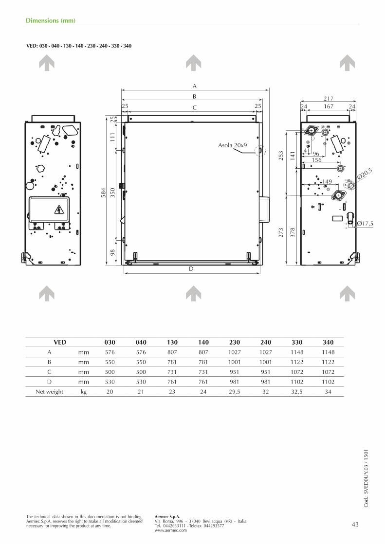
43The technical data shown in this documentation is not binding. Aermec S.p.A. reserves the right to make all modification deemed necessary for improving the product at any time.
Aermec S.p.A.Via Roma, 996 - 37040 Bevilacqua (VR) - ItaliaTel. 0442633111 - Telefax 044293577www.aermec.com
Cod
.: SV
ED0U
Y.03
/ 15
01
Dimensions (mm)
VED: 030 - 040 - 130 - 140 - 230 - 240 - 330 - 340
VED 030 040 130 140 230 240 330 340
A mm 576 576 807 807 1027 1027 1148 1148
B mm 550 550 781 781 1001 1001 1122 1122
C mm 500 500 731 731 951 951 1072 1072
D mm 530 530 761 761 981 981 1102 1102
Net weight kg 20 21 23 24 29,5 32 32,5 34
41
Ø17,5
A
Asola 20x9
2511
1
584
253
141
378
273
350
9825
217
Ø20,5
167
156
149
96
24 2425
B
C
D
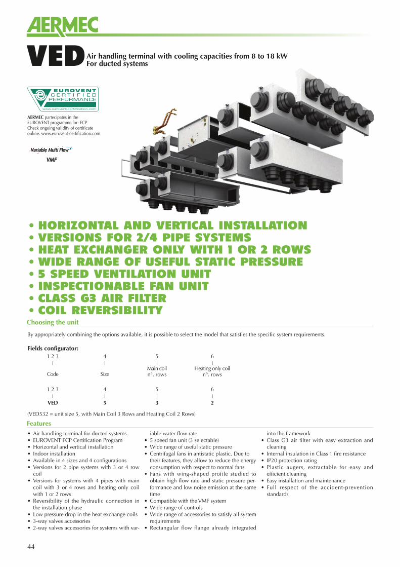
44
Air handling terminal with cooling capacities from 8 to 18 kWFor ducted systemsVED
• Air handling terminal for ducted systems• EUROVENT FCP Certification Program• Horizontal and vertical installation• Indoor installation• Available in 4 sizes and 4 configurations• Versions for 2 pipe systems with 3 or 4 row
coil• Versions for systems with 4 pipes with main
coil with 3 or 4 rows and heating only coil with 1 or 2 rows
• Reversibility of the hydraulic connection in the installation phase
• Low pressure drop in the heat exchange coils• 3-way valves accessories• 2-way valves accessories for systems with var-
iable water flow rate• 5 speed fan unit (3 selectable)• Wide range of useful static pressure• Centrifugal fans in antistatic plastic. Due to
their features, they allow to reduce the energy consumption with respect to normal fans
• Fans with wing-shaped profile studied to obtain high flow rate and static pressure per-formance and low noise emission at the same time
• Compatible with the VMF system• Wide range of controls• Wide range of accessories to satisfy all system
requirements• Rectangular flow flange already integrated
into the framework• Class G3 air filter with easy extraction and
cleaning• Internal insulation in Class 1 fire resistance• IP20 protection rating• Plastic augers, extractable for easy and
efficient cleaning• Easy installation and maintenance• Full respect of the accident-prevention
standards
Features
Choosing the unit
By appropriately combining the options available, it is possible to select the model that satisfies the specific system requirements.
(VED532 = unit size 5, with Main Coil 3 Rows and Heating Coil 2 Rows)
Fields configurator:1 2 3 4 5 6
❘ ❘ ❘ ❘
Code SizeMain coiln°. rows
Heating only coiln°. rows
1 2 3 4 5 6❘ ❘ ❘ ❘
VED 5 3 2
AERMEC partecipates in the EUROVENT programme for: FCPCheck ongoing validity of certificate online: www.eurovent-certification.com
• HORIZONTAL AND VERTICAL INSTALLATION• VERSIONS FOR 2/4 PIPE SYSTEMS • HEAT EXCHANGER ONLY WITH 1 OR 2 ROWS• WIDE RANGE OF USEFUL STATIC PRESSURE• 5 SPEED VENTILATION UNIT • INSPECTIONABLE FAN UNIT• CLASS G3 AIR FILTER• COIL REVERSIBILITY
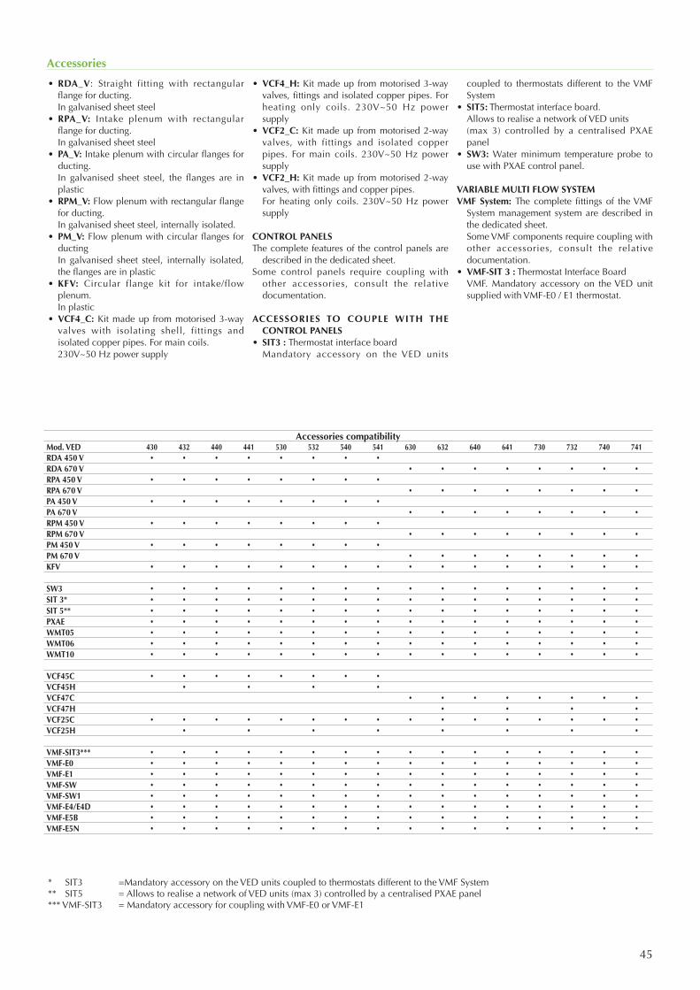
45
• RDA_V: Straight fitting with rectangular flange for ducting.
In galvanised sheet steel• RPA_V: Intake plenum with rectangular
flange for ducting. In galvanised sheet steel• PA_V: Intake plenum with circular flanges for
ducting. In galvanised sheet steel, the flanges are in
plastic• RPM_V: Flow plenum with rectangular flange
for ducting. In galvanised sheet steel, internally isolated.• PM_V: Flow plenum with circular flanges for
ducting In galvanised sheet steel, internally isolated,
the flanges are in plastic• KFV: Circular flange kit for intake/flow
plenum. In plastic• VCF4_C: Kit made up from motorised 3-way
valves with isolating shell, fittings and isolated copper pipes. For main coils.
230V~50 Hz power supply
• VCF4_H: Kit made up from motorised 3-way valves, fittings and isolated copper pipes. For heating only coils. 230V~50 Hz power supply
• VCF2_C: Kit made up from motorised 2-way valves, with fittings and isolated copper pipes. For main coils. 230V~50 Hz power supply
• VCF2_H: Kit made up from motorised 2-way valves, with fittings and copper pipes.
For heating only coils. 230V~50 Hz power supply
CONTROL PANELSThe complete features of the control panels are
described in the dedicated sheet.Some control panels require coupling with
other accessories, consult the relative documentation.
ACCESSORIES TO COUPLE WITH THE CONTROL PANELS
• SIT3 : Thermostat interface board Mandatory accessory on the VED units
coupled to thermostats different to the VMF System
• SIT5: Thermostat interface board. Allows to realise a network of VED units (max 3) controlled by a centralised PXAE
panel• SW3: Water minimum temperature probe to
use with PXAE control panel.
VARIABLE MULTI FLOW SYSTEMVMF System: The complete fittings of the VMF
System management system are described in the dedicated sheet.
Some VMF components require coupling with other accessories, consult the relative documentation.
• VMF-SIT 3 : Thermostat Interface Board VMF. Mandatory accessory on the VED unit
supplied with VMF-E0 / E1 thermostat.
Accessories
* SIT3 =Mandatory accessory on the VED units coupled to thermostats different to the VMF System** SIT5 = Allows to realise a network of VED units (max 3) controlled by a centralised PXAE panel*** VMF-SIT3 = Mandatory accessory for coupling with VMF-E0 or VMF-E1
Accessories compatibilityMod. VED 430 432 440 441 530 532 540 541 630 632 640 641 730 732 740 741RDA 450 V • • • • • • • •
RDA 670 V • • • • • • • •
RPA 450 V • • • • • • • •
RPA 670 V • • • • • • • •
PA 450 V • • • • • • • •
PA 670 V • • • • • • • •
RPM 450 V • • • • • • • •
RPM 670 V • • • • • • • •
PM 450 V • • • • • • • •
PM 670 V • • • • • • • •
KFV • • • • • • • • • • • • • • • •
SW3 • • • • • • • • • • • • • • • •
SIT 3* • • • • • • • • • • • • • • • •
SIT 5** • • • • • • • • • • • • • • • •
PXAE • • • • • • • • • • • • • • • •
WMT05 • • • • • • • • • • • • • • • •
WMT06 • • • • • • • • • • • • • • • •
WMT10 • • • • • • • • • • • • • • • •
VCF45C • • • • • • • •
VCF45H • • • •
VCF47C • • • • • • • •
VCF47H • • • •
VCF25C • • • • • • • • • • • • • • • •
VCF25H • • • • • • • •
VMF-SIT3*** • • • • • • • • • • • • • • • •
VMF-E0 • • • • • • • • • • • • • • • •
VMF-E1 • • • • • • • • • • • • • • • •
VMF-SW • • • • • • • • • • • • • • • •
VMF-SW1 • • • • • • • • • • • • • • • •
VMF-E4/E4D • • • • • • • • • • • • • • • •
VMF-E5B • • • • • • • • • • • • • • • •
VMF-E5N • • • • • • • • • • • • • • • •
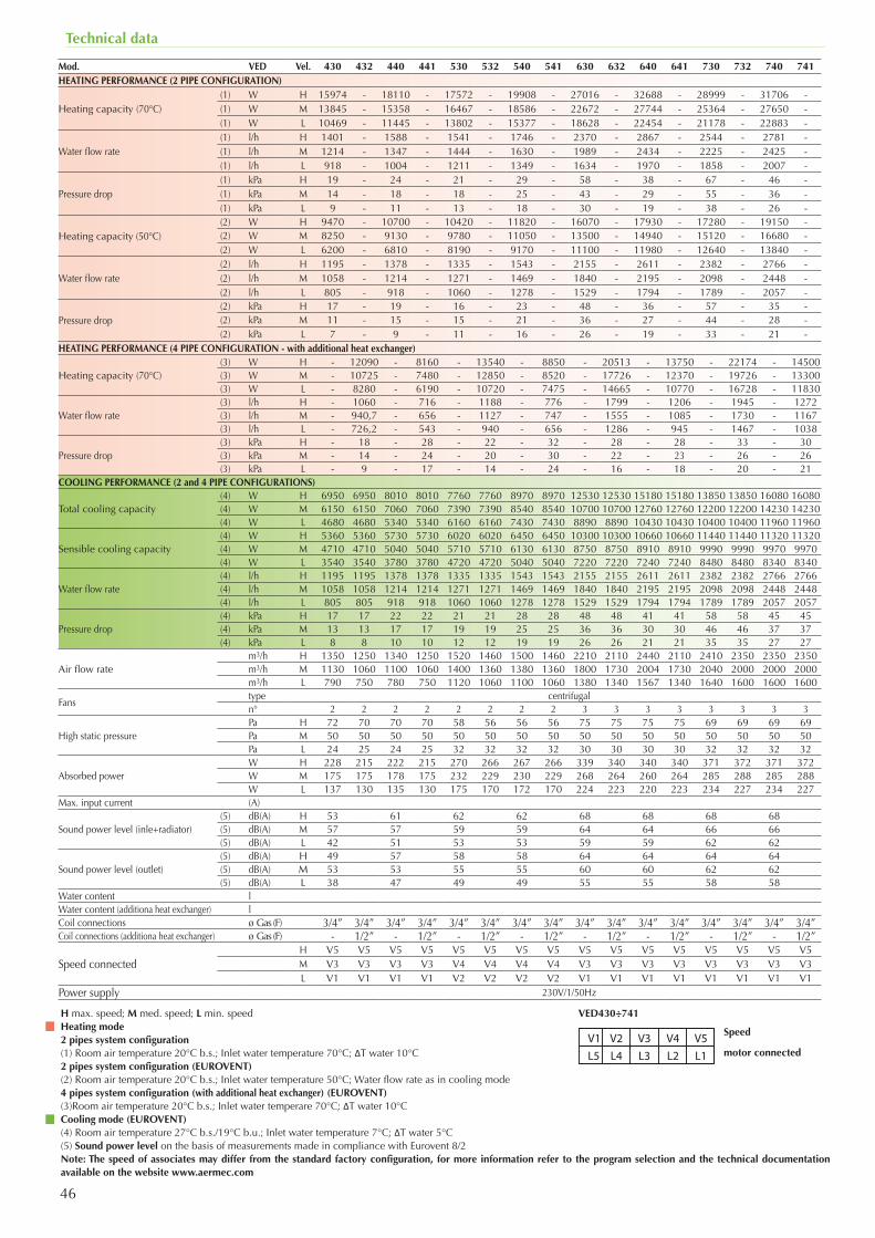
46
Technical data
Mod. VED Vel. 430 432 440 441 530 532 540 541 630 632 640 641 730 732 740 741HEATING PERFORMANCE (2 PIPE CONFIGURATION)
Heating capacity (70°C)(1) W H 15974 - 18110 - 17572 - 19908 - 27016 - 32688 - 28999 - 31706 -(1) W M 13845 - 15358 - 16467 - 18586 - 22672 - 27744 - 25364 - 27650 -(1) W L 10469 - 11445 - 13802 - 15377 - 18628 - 22454 - 21178 - 22883 -
Water flow rate(1) l/h H 1401 - 1588 - 1541 - 1746 - 2370 - 2867 - 2544 - 2781 -(1) l/h M 1214 - 1347 - 1444 - 1630 - 1989 - 2434 - 2225 - 2425 -(1) l/h L 918 - 1004 - 1211 - 1349 - 1634 - 1970 - 1858 - 2007 -
Pressure drop(1) kPa H 19 - 24 - 21 - 29 - 58 - 38 - 67 - 46 -(1) kPa M 14 - 18 - 18 - 25 - 43 - 29 - 55 - 36 -(1) kPa L 9 - 11 - 13 - 18 - 30 - 19 - 38 - 26 -
Heating capacity (50°C)(2) W H 9470 - 10700 - 10420 - 11820 - 16070 - 17930 - 17280 - 19150 -(2) W M 8250 - 9130 - 9780 - 11050 - 13500 - 14940 - 15120 - 16680 -(2) W L 6200 - 6810 - 8190 - 9170 - 11100 - 11980 - 12640 - 13840 -
Water flow rate(2) l/h H 1195 - 1378 - 1335 - 1543 - 2155 - 2611 - 2382 - 2766 -(2) l/h M 1058 - 1214 - 1271 - 1469 - 1840 - 2195 - 2098 - 2448 -(2) l/h L 805 - 918 - 1060 - 1278 - 1529 - 1794 - 1789 - 2057 -
Pressure drop(2) kPa H 17 - 19 - 16 - 23 - 48 - 36 - 57 - 35 -(2) kPa M 11 - 15 - 15 - 21 - 36 - 27 - 44 - 28 -(2) kPa L 7 - 9 - 11 - 16 - 26 - 19 - 33 - 21 -
HEATING PERFORMANCE (4 PIPE CONFIGURATION - with additional heat exchanger)
Heating capacity (70°C)(3) W H - 12090 - 8160 - 13540 - 8850 - 20513 - 13750 - 22174 - 14500(3) W M - 10725 - 7480 - 12850 - 8520 - 17726 - 12370 - 19726 - 13300(3) W L - 8280 - 6190 - 10720 - 7475 - 14665 - 10770 - 16728 - 11830
Water flow rate(3) l/h H - 1060 - 716 - 1188 - 776 - 1799 - 1206 - 1945 - 1272(3) l/h M - 940,7 - 656 - 1127 - 747 - 1555 - 1085 - 1730 - 1167(3) l/h L - 726,2 - 543 - 940 - 656 - 1286 - 945 - 1467 - 1038
Pressure drop(3) kPa H - 18 - 28 - 22 - 32 - 28 - 28 - 33 - 30(3) kPa M - 14 - 24 - 20 - 30 - 22 - 23 - 26 - 26(3) kPa L - 9 - 17 - 14 - 24 - 16 - 18 - 20 - 21
COOLING PERFORMANCE (2 and 4 PIPE CONFIGURATIONS)
Total cooling capacity(4) W H 6950 6950 8010 8010 7760 7760 8970 8970 12530 12530 15180 15180 13850 13850 16080 16080(4) W M 6150 6150 7060 7060 7390 7390 8540 8540 10700 10700 12760 12760 12200 12200 14230 14230(4) W L 4680 4680 5340 5340 6160 6160 7430 7430 8890 8890 10430 10430 10400 10400 11960 11960
Sensible cooling capacity(4) W H 5360 5360 5730 5730 6020 6020 6450 6450 10300 10300 10660 10660 11440 11440 11320 11320(4) W M 4710 4710 5040 5040 5710 5710 6130 6130 8750 8750 8910 8910 9990 9990 9970 9970(4) W L 3540 3540 3780 3780 4720 4720 5040 5040 7220 7220 7240 7240 8480 8480 8340 8340
Water flow rate (4) l/h H 1195 1195 1378 1378 1335 1335 1543 1543 2155 2155 2611 2611 2382 2382 2766 2766(4) l/h M 1058 1058 1214 1214 1271 1271 1469 1469 1840 1840 2195 2195 2098 2098 2448 2448(4) l/h L 805 805 918 918 1060 1060 1278 1278 1529 1529 1794 1794 1789 1789 2057 2057
Pressure drop(4) kPa H 17 17 22 22 21 21 28 28 48 48 41 41 58 58 45 45(4) kPa M 13 13 17 17 19 19 25 25 36 36 30 30 46 46 37 37(4) kPa L 8 8 10 10 12 12 19 19 26 26 21 21 35 35 27 27
Air flow ratem3/h H 1350 1250 1340 1250 1520 1460 1500 1460 2210 2110 2440 2110 2410 2350 2350 2350m3/h M 1130 1060 1100 1060 1400 1360 1380 1360 1800 1730 2004 1730 2040 2000 2000 2000m3/h L 790 750 780 750 1120 1060 1100 1060 1380 1340 1567 1340 1640 1600 1600 1600
Fanstype centrifugaln° 2 2 2 2 2 2 2 2 3 3 3 3 3 3 3 3
High static pressurePa H 72 70 70 70 58 56 56 56 75 75 75 75 69 69 69 69Pa M 50 50 50 50 50 50 50 50 50 50 50 50 50 50 50 50Pa L 24 25 24 25 32 32 32 32 30 30 30 30 32 32 32 32
Absorbed powerW H 228 215 222 215 270 266 267 266 339 340 340 340 371 372 371 372W M 175 175 178 175 232 229 230 229 268 264 260 264 285 288 285 288W L 137 130 135 130 175 170 172 170 224 223 220 223 234 227 234 227
Max. input current (A)
Sound power level (inle+radiator)(5) dB(A) H 53 61 62 62 68 68 68 68(5) dB(A) M 57 57 59 59 64 64 66 66(5) dB(A) L 42 51 53 53 59 59 62 62
Sound power level (outlet)(5) dB(A) H 49 57 58 58 64 64 64 64(5) dB(A) M 53 53 55 55 60 60 62 62(5) dB(A) L 38 47 49 49 55 55 58 58
Water content lWater content (additiona heat exchanger) lCoil connections ø Gas (F) 3/4” 3/4” 3/4” 3/4” 3/4” 3/4” 3/4” 3/4” 3/4” 3/4” 3/4” 3/4” 3/4” 3/4” 3/4” 3/4”Coil connections (additiona heat exchanger) ø Gas (F) - 1/2” - 1/2” - 1/2” - 1/2” - 1/2” - 1/2” - 1/2” - 1/2”
Speed connectedH V5 V5 V5 V5 V5 V5 V5 V5 V5 V5 V5 V5 V5 V5 V5 V5M V3 V3 V3 V3 V4 V4 V4 V4 V3 V3 V3 V3 V3 V3 V3 V3L V1 V1 V1 V1 V2 V2 V2 V2 V1 V1 V1 V1 V1 V1 V1 V1
Power supply 230V/1/50Hz
H max. speed; M med. speed; L min. speedHeating mode2 pipes system configuration(1) Room air temperature 20°C b.s.; Inlet water temperature 70°C; ΔT water 10°C2 pipes system configuration (EUROVENT)(2) Room air temperature 20°C b.s.; Inlet water temperature 50°C; Water flow rate as in cooling mode4 pipes system configuration (with additional heat exchanger) (EUROVENT)(3)Room air temperature 20°C b.s.; Inlet water temperare 70°C; ΔT water 10°CCooling mode (EUROVENT)(4) Room air temperature 27°C b.s./19°C b.u.; Inlet water temperature 7°C; ΔT water 5°C(5) Sound power level on the basis of measurements made in compliance with Eurovent 8/2Note: The speed of associates may differ from the standard factory configuration, for more information refer to the program selection and the technical documentation available on the website www.aermec.com
L5 L4 L3 L2 L1 V1 V2 V3 V4 V5 Speed
motor connected
VED430÷741
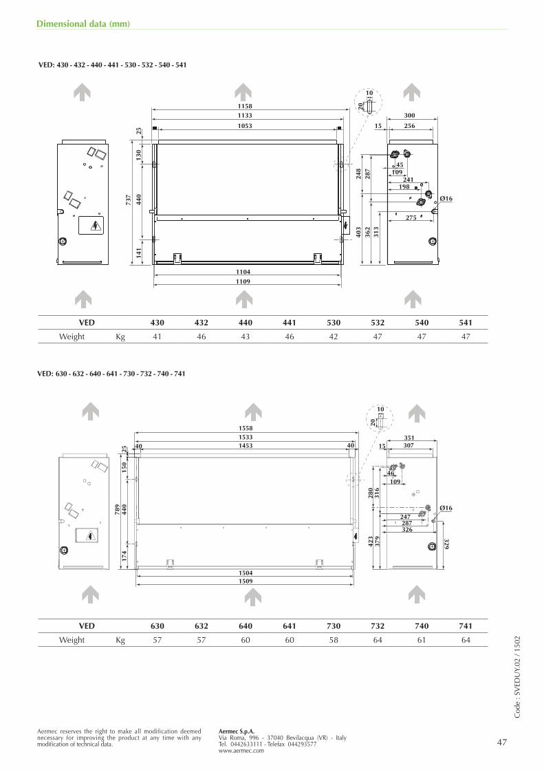
Aermec S.p.A.Via Roma, 996 - 37040 Bevilacqua (VR) - ItalyTel. 0442633111 - Telefax 044293577www.aermec.com
47Aermec reserves the right to make all modification deemed necessary for improving the product at any time with any modification of technical data.
Cod
e : S
VED
UY.
02 /
1502
Dimensional data (mm)
VED: 430 - 432 - 440 - 441 - 530 - 532 - 540 - 541
VED: 630 - 632 - 640 - 641 - 730 - 732 - 740 - 741
1133
1053
1104
440
737
141
130
25
300
25615
248
287
403
362
313
45109
241198
275
Ø16
10
201158
1109
= =
1133
1053
110444
0
737
141
130
25
300
25615
248
287
403
362
313
45109
241198
275
Ø16
10
201158
1109
Ø16
15091504
789
150
440
174
25
15581533145340 40
329423
280
316
351307
109
379
15
326
247287
46
10
20
VED 430 432 440 441 530 532 540 541
Weight Kg 41 46 43 46 42 47 47 47
VED 630 632 640 641 730 732 740 741
Weight Kg 57 57 60 60 58 64 61 64
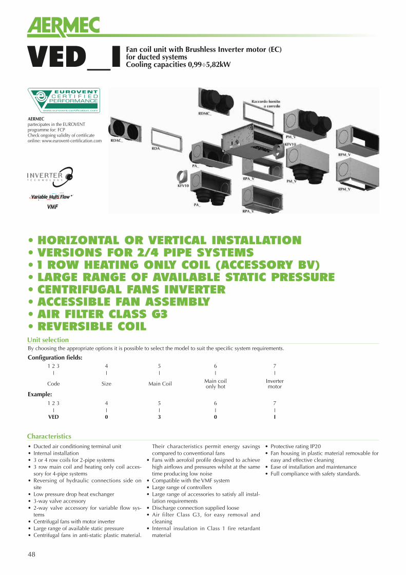
48
Fan coil unit with Brushless Inverter motor (EC) for ducted systemsCooling capacities 0,99÷5,82kWVED_I
• Ducted air conditioning terminal unit• Internal installation• 3 or 4 row coils for 2-pipe systems• 3 row main coil and heating only coil acces-
sory for 4-pipe systems • Reversing of hydraulic connections side on
site• Low pressure drop heat exchanger• 3-way valve accessory • 2-way valve accessory for variable flow sys-
tems• Centrifugal fans with motor inverter• Large range of available static pressure• Centrifugal fans in anti-static plastic material.
Their characteristics permit energy savings compared to conventional fans
• Fans with aerofoil profile designed to achieve high airflows and pressures whilst at the same time producing low noise
• Compatible with the VMF system• Large range of controllers • Large range of accessories to satisfy all instal-
lation requirements• Discharge connection supplied loose• Air filter Class G3, for easy removal and
cleaning• Internal insulation in Class 1 fire retardant
material
• Protective rating IP20• Fan housing in plastic material removable for
easy and effective cleaning• Ease of installation and maintenance• Full compliance with safety standards.
Characteristics
Unit selectionBy choosing the appropriate options it is possible to select the model to suit the specific system requirements.
Configuration fields:
Example:
• HORIZONTAL OR VERTICAL INSTALLATION• VERSIONS FOR 2/4 PIPE SYSTEMS • 1 ROW HEATING ONLY COIL (ACCESSORY BV)• LARGE RANGE OF AVAILABLE STATIC PRESSURE• CENTRIFUGAL FANS INVERTER• ACCESSIBLE FAN ASSEMBLY• AIR FILTER CLASS G3• REVERSIBLE COIL
1 2 3 4 5 6 7❘ ❘ ❘ ❘ ❘
Code Size Main Coil Main coilonly hot
Invertermotor
1 2 3 4 5 6 7❘ ❘ ❘ ❘ ❘
VED 0 3 0 I
AERMEC partecipates in the EUROVENT programme for: FCPCheck ongoing validity of certificate online: www.eurovent-certification.com
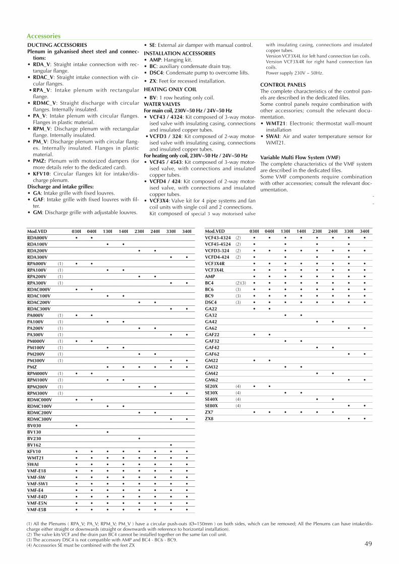
49
Accessories
Compatibilità accessori
DUCTING ACCESSORIES Plenum in galvanised sheet steel and connec-
tions:• RDA_V: Straight intake connection with rec-
tangular flange.• RDAC_V: Straight intake connection with cir-
cular flanges. • RPA_V: Intake plenum with rectangular
flange.• RDMC_V: Straight discharge with circular
flanges. Internally insulated.• PA_V: Intake plenum with circular flanges.
Flanges in plastic material.• RPM_V: Discharge plenum with rectangular
flange. Internally insulated.• PM_V: Discharge plenum with circular flang-
es. Internally insulated. Flanges in plastic material.
• PMZ: Plenum with motorized dampers (for more details refer to the dedicated card).
• KFV10: Circular flanges kit for intake/dis-charge plenum.
Discharge and intake grilles:• GA: Intake grille with fixed louvres.• GAF: Intake grille with fixed louvres with fil-
ter.• GM: Discharge grille with adjustable louvres.
• SE: External air damper with manual control.
INSTALLATION ACCESSORIES• AMP: Hanging kit.• BC: auxiliary condensate drain tray.• DSC4: Condensate pump to overcome lifts.
• ZX: Feet for recessed installation.
HEATING ONLY COIL
• BV: 1 row heating only coil. WATER VALVESFor main coil, 230V~50 Hz / 24V~50 Hz• VCF43 / 4324: Kit composed of 3-way motor-
ised valve with insulating casing, connections and insulated copper tubes.
• VCFD3 / 324: Kit composed of 2-way motor-ised valve with insulating casing, connections and insulated copper tubes.
For heating only coil, 230V~50 Hz / 24V~50 Hz• VCF45 / 4543: Kit composed of 3-way motor-
ised valve, with connections and insulated copper tubes.
• VCFD4 / 424: Kit composed of 2-way motor-ised valve, with connections and insulated copper tubes.
• VCF3X4: Valve kit for 4 pipe systems and fan coil units with single coil and 2 connections.
Kit composed of special 3 way motorised valve
with insulating casing, connections and insulated copper tubes.
Version VCF3X4L for left hand connection fan coils. Version VCF3X4R for right hand connection fan
coils. Power supply 230V ~ 50Hz.
CONTROL PANELSThe complete characteristics of the control pan-els are described in the dedicated files.Some control panels require combination with other accessories; consult the relevant docu-mentation. • WMT21: Electronic thermostat wall-mount
installation• SWAI: Air and water temperature sensor for
WMT21.
Variable Multi Flow System (VMF)The complete characteristics of the VMF system are described in the dedicated files. Some VMF components require combination with other accessories; consult the relevant doc-umentation.
(1) All the Plenums ( RPA_V; PA_V; RPM_V; PM_V ) have a circular push-outs (Ø=150mm ) on both sides, which can be removed; All the Plenums can have intake/dis-charge either straight or downwards (straight or downwards with reference to horizontal installation).(2) The valve kits VCF and the drain pan BC4 cannot be installed together on the same fan coil unit.(3) The accessory DSC4 is not compatible with AMP and BC4 - BC6 - BC9.(4) Accessories SE must be combined with the feet ZX
Mod.VED 030I 040I 130I 140I 230I 240I 330I 340IRDA000V • •RDA100V • •RDA200V • •RDA300V • •RPA000V (1) • •RPA100V (1) • •RPA200V (1) • •RPA300V (1) • •RDAC000V • •RDAC100V • •RDAC200V • •RDAC300V • •PA000V (1) • •PA100V (1) • •PA200V (1) • •PA300V (1) • •PM000V (1) • •PM100V (1) • •PM200V (1) • •PM300V (1) • •PMZ • • • • • •RPM000V (1) • •RPM100V (1) • •RPM200V (1) • •RPM300V (1) • •RDMC000V • •RDMC100V • •RDMC200V • •RDMC300V • •BV030 •BV130 •BV230 •BV162 •KFV10 • • • • • • • •WMT21 • • • • • • • •SWAI • • • • • • • •VMF-E18 • • • • • • • •VMF-SW • • • • • • • •VMF-SW1 • • • • • • • •VMF-E4 • • • • • • • •VMF-E4D • • • • • • • •VMF-E5N • • • • • • • •VMF-E5B • • • • • • • •
Mod.VED 030I 040I 130I 140I 230I 240I 330I 340IVCF43-4324 (2) • • • • • • • •VCF45-4524 (2) • • • •VCFD3-324 (2) • • • • • • • •VCFD4-424 (2) • • • •VCF3X4R • • • • • • • •VCF3X4L • • • • • • • •AMP • • • • • • • •BC4 (2)(3) • • • • • • • •BC6 (3) • • • • • • • •BC9 (3) • • • • • • • •DSC4 (3) • • • • • • • •GA22 • •GA32 • •GA42 • •GA62 • •GAF22 • •GAF32 • •GAF42 • •GAF62 • •GM22 • •GM32 • •GM42 • •GM62 • •SE20X (4) • •SE30X (4) • •SE40X (4) • •SE80X (4) • •ZX7 • • • • • •ZX8 • •
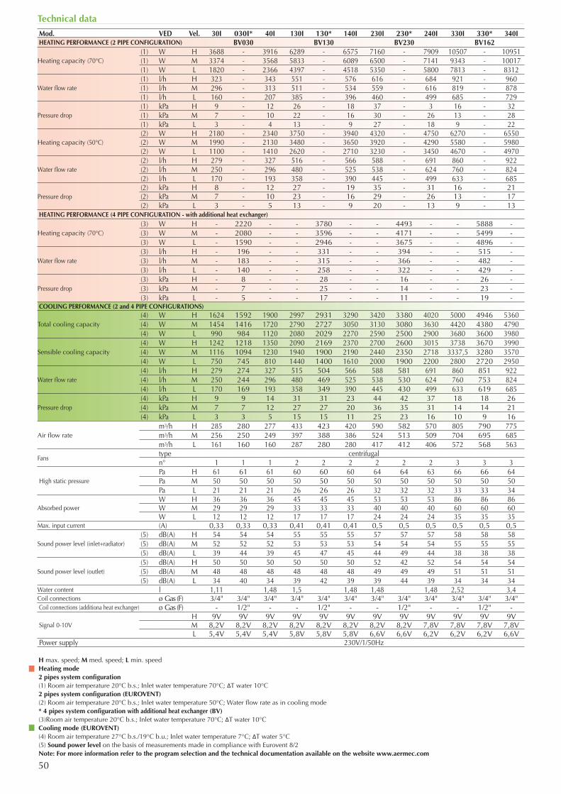
50
Technical data
H max. speed; M med. speed; L min. speedHeating mode2 pipes system configuration(1) Room air temperature 20°C b.s.; Inlet water temperature 70°C; ΔT water 10°C2 pipes system configuration (EUROVENT)(2) Room air temperature 20°C b.s.; Inlet water temperature 50°C; Water flow rate as in cooling mode* 4 pipes system configuration with additional heat exchanger (BV)(3)Room air temperature 20°C b.s.; Inlet water temperature 70°C; ΔT water 10°CCooling mode (EUROVENT)(4) Room air temperature 27°C b.s./19°C b.u.; Inlet water temperature 7°C; ΔT water 5°C(5) Sound power level on the basis of measurements made in compliance with Eurovent 8/2Note: For more information refer to the program selection and the technical documentation available on the website www.aermec.com
Mod. VED Vel. 30I 030I* 40I 130I 130* 140I 230I 230* 240I 330I 330* 340IHEATING PERFORMANCE (2 PIPE CONFIGURATION) BV030 BV130 BV230 BV162
Heating capacity (70°C)(1) W H 3688 - 3916 6289 - 6575 7160 - 7909 10507 - 10951(1) W M 3374 - 3568 5833 - 6089 6500 - 7141 9343 - 10017(1) W L 1820 - 2366 4397 - 4518 5350 - 5800 7813 - 8312
Water flow rate(1) l/h H 323 - 343 551 - 576 616 - 684 921 - 960(1) l/h M 296 - 313 511 - 534 559 - 616 819 - 878(1) l/h L 160 - 207 385 - 396 460 - 499 685 - 729
Pressure drop(1) kPa H 9 - 12 26 - 18 37 - 3 16 - 32(1) kPa M 7 - 10 22 - 16 30 - 26 13 - 28(1) kPa L 3 - 4 13 - 9 27 - 18 9 - 22
Heating capacity (50°C)(2) W H 2180 - 2340 3750 - 3940 4320 - 4750 6270 - 6550(2) W M 1990 - 2130 3480 - 3650 3920 - 4290 5580 - 5980(2) W L 1100 - 1410 2620 - 2710 3230 - 3450 4670 - 4970
Water flow rate(2) l/h H 279 - 327 516 - 566 588 - 691 860 - 922(2) l/h M 250 - 296 480 - 525 538 - 624 760 - 824(2) l/h L 170 - 193 358 - 390 445 - 499 633 - 685
Pressure drop(2) kPa H 8 - 12 27 - 19 35 - 31 16 - 21(2) kPa M 7 - 10 23 - 16 29 - 26 13 - 17(2) kPa L 3 - 5 13 - 9 20 - 13 9 - 13
HEATING PERFORMANCE (4 PIPE CONFIGURATION - with additional heat exchanger)
Heating capacity (70°C)(3) W H - 2220 - - 3780 - - 4493 - - 5888 -(3) W M - 2080 - - 3596 - - 4171 - - 5499 -(3) W L - 1590 - - 2946 - - 3675 - - 4896 -
Water flow rate(3) l/h H - 196 - - 331 - - 394 - - 515 -(3) l/h M - 183 - - 315 - - 366 - - 482 -(3) l/h L - 140 - - 258 - - 322 - - 429 -
Pressure drop(3) kPa H - 8 - - 28 - - 16 - - 26 -(3) kPa M - 7 - - 25 - - 14 - - 23 -(3) kPa L - 5 - - 17 - - 11 - - 19 -
COOLING PERFORMANCE (2 and 4 PIPE CONFIGURATIONS)
Total cooling capacity(4) W H 1624 1592 1900 2997 2931 3290 3420 3380 4020 5000 4946 5360(4) W M 1454 1416 1720 2790 2727 3050 3130 3080 3630 4420 4380 4790(4) W L 990 984 1120 2080 2029 2270 2590 2500 2900 3680 3600 3980
Sensible cooling capacity(4) W H 1242 1218 1350 2090 2169 2370 2700 2600 3015 3738 3670 3990(4) W M 1116 1094 1230 1940 1900 2190 2440 2350 2718 3337,5 3280 3570(4) W L 750 745 810 1440 1400 1610 2000 1900 2200 2800 2720 2950
Water flow rate (4) l/h H 279 274 327 515 504 566 588 581 691 860 851 922(4) l/h M 250 244 296 480 469 525 538 530 624 760 753 824(4) l/h L 170 169 193 358 349 390 445 430 499 633 619 685
Pressure drop(4) kPa H 9 9 14 31 31 23 44 42 37 18 18 26(4) kPa M 7 7 12 27 27 20 36 35 31 14 14 21(4) kPa L 3 3 5 15 15 11 25 23 16 10 9 16
Air flow ratem3/h H 285 280 277 433 423 420 590 582 570 805 790 775m3/h M 256 250 249 397 388 386 524 513 509 704 695 685m3/h L 161 160 160 287 280 280 417 412 406 572 568 563
Fanstype centrifugaln° 1 1 1 2 2 2 2 2 2 3 3 3
High static pressurePa H 61 61 61 60 60 60 64 64 63 66 66 64Pa M 50 50 50 50 50 50 50 50 50 50 50 50Pa L 21 21 21 26 26 26 32 32 32 33 33 34
Absorbed powerW H 36 36 36 45 45 45 53 53 53 86 86 86W M 29 29 29 33 33 33 40 40 40 60 60 60W L 12 12 12 17 17 17 24 24 24 35 35 35
Max. input current (A) 0,33 0,33 0,33 0,41 0,41 0,41 0,5 0,5 0,5 0,5 0,5 0,5
Sound power level (inlet+radiator)(5) dB(A) H 54 54 54 55 55 55 57 57 57 58 58 58(5) dB(A) M 52 52 52 53 53 53 54 54 54 55 55 55(5) dB(A) L 39 44 39 45 47 45 44 49 44 38 38 38
Sound power level (outlet)(5) dB(A) H 50 50 50 50 50 50 52 42 52 54 54 54(5) dB(A) M 48 48 48 48 48 48 49 49 49 51 51 51(5) dB(A) L 34 40 34 39 42 39 39 44 39 34 34 34
Water content l 1,11 1,48 1,5 1,48 1,48 1,48 2,52 3,4Coil connections ø Gas (F) 3/4" 3/4" 3/4" 3/4" 3/4" 3/4" 3/4" 3/4" 3/4" 3/4" 3/4" 3/4"Coil connections (additiona heat exchanger) ø Gas (F) - 1/2" - - 1/2" - - 1/2" - - 1/2" -
Signal 0-10VH 9V 9V 9V 9V 9V 9V 9V 9V 9V 9V 9V 9VM 8,2V 8,2V 8,2V 8,2V 8,2V 8,2V 8,2V 8,2V 7,8V 7,8V 7,8V 7,8VL 5,4V 5,4V 5,4V 5,8V 5,8V 5,8V 6,6V 6,6V 6,2V 6,2V 6,2V 6,6V
Power supply 230V/1/50Hz
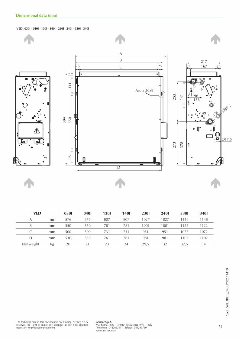
51The technical data in this document is not binding. Aermec S.p.A. reserves the right to make any changes at any time deemed necessary for product improvement.
Aermec S.p.A.Via Roma, 996 - 37040 Bevilacqua (VR) - ItalyTelephone 0442633111 - Telefax 044293730www.aermec.com
Cod
.: SV
EDI0
30_3
40U
Y.02
/ 14
10
Dimensional data (mm)
VED: 030I - 040I - 130I - 140I - 230I - 240I - 330I - 340I
VED 030I 040I 130I 140I 230I 240I 330I 340I
A mm 576 576 807 807 1027 1027 1148 1148
B mm 550 550 781 781 1001 1001 1122 1122
C mm 500 500 731 731 951 951 1072 1072
D mm 530 530 761 761 981 981 1102 1102
Net weight Kg 20 21 23 24 29,5 32 32,5 34
41
Ø17,5
A
Asola 20x9
2511
1
584
253
141
378
273
350
9825
217
Ø20,5
167
156
149
96
24 2425
B
C
D
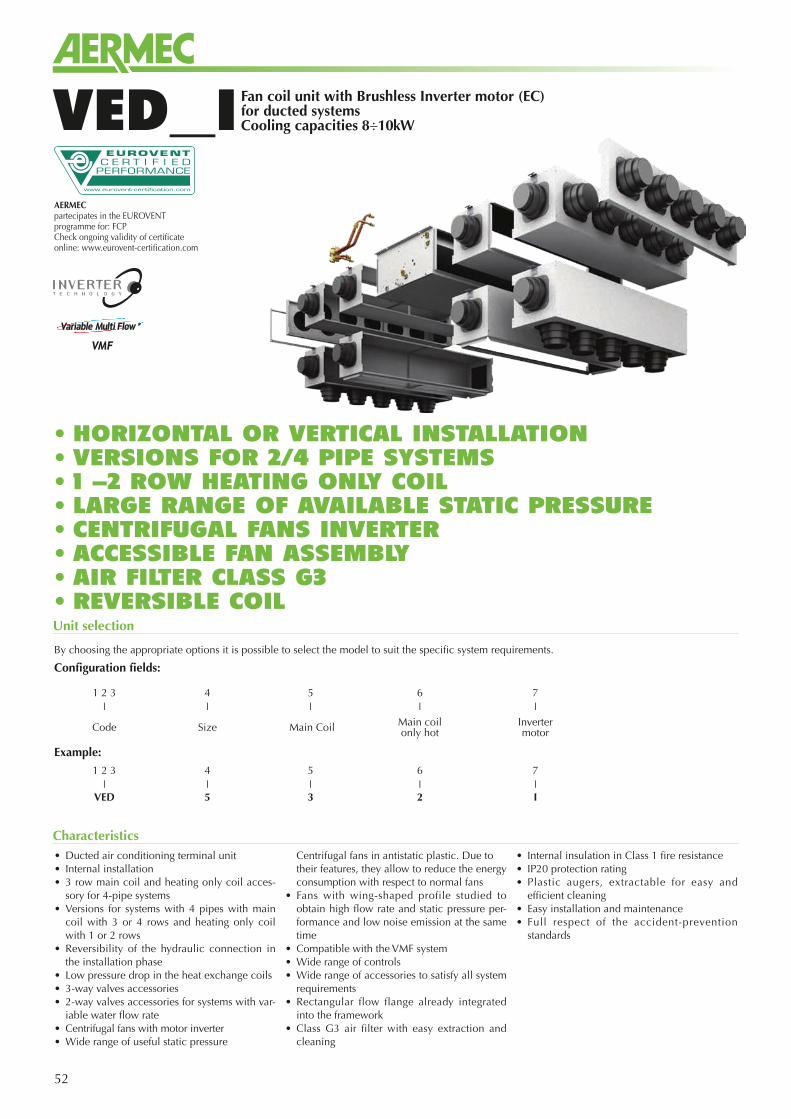
52
Fan coil unit with Brushless Inverter motor (EC) for ducted systemsCooling capacities 8÷10kWVED_I
• Ducted air conditioning terminal unit• Internal installation• 3 row main coil and heating only coil acces-
sory for 4-pipe systems• Versions for systems with 4 pipes with main
coil with 3 or 4 rows and heating only coil with 1 or 2 rows
• Reversibility of the hydraulic connection in the installation phase
• Low pressure drop in the heat exchange coils• 3-way valves accessories• 2-way valves accessories for systems with var-
iable water flow rate• Centrifugal fans with motor inverter• Wide range of useful static pressure
Centrifugal fans in antistatic plastic. Due to their features, they allow to reduce the energy consumption with respect to normal fans
• Fans with wing-shaped profile studied to obtain high flow rate and static pressure per-formance and low noise emission at the same time
• Compatible with the VMF system• Wide range of controls• Wide range of accessories to satisfy all system
requirements• Rectangular flow flange already integrated
into the framework• Class G3 air filter with easy extraction and
cleaning
• Internal insulation in Class 1 fire resistance• IP20 protection rating• Plastic augers, extractable for easy and
efficient cleaning• Easy installation and maintenance• Full respect of the accident-prevention
standards
Characteristics
Unit selection
By choosing the appropriate options it is possible to select the model to suit the specific system requirements.
Configuration fields:
Example:
• HORIZONTAL OR VERTICAL INSTALLATION• VERSIONS FOR 2/4 PIPE SYSTEMS • 1 -2 ROW HEATING ONLY COIL• LARGE RANGE OF AVAILABLE STATIC PRESSURE• CENTRIFUGAL FANS INVERTER• ACCESSIBLE FAN ASSEMBLY• AIR FILTER CLASS G3• REVERSIBLE COIL
1 2 3 4 5 6 7❘ ❘ ❘ ❘ ❘
Code Size Main Coil Main coilonly hot
Invertermotor
1 2 3 4 5 6 7❘ ❘ ❘ ❘ ❘
VED 5 3 2 I
AERMEC partecipates in the EUROVENT programme for: FCPCheck ongoing validity of certificate online: www.eurovent-certification.com
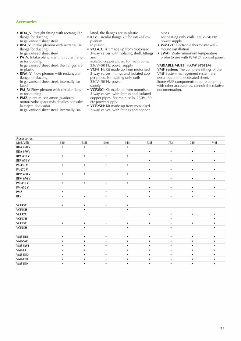
53
Accessori
• RDA_V: Straight fitting with rectangular flange for ducting.
In galvanised sheet steel• RPA_V: Intake plenum with rectangular
flange for ducting. In galvanised sheet steel• PA_V: Intake plenum with circular flang-
es for ducting. In galvanised sheet steel, the flanges are
in plastic• RPM_V: Flow plenum with rectangular
flange for ducting. In galvanised sheet steel, internally iso-
lated.• PM_V: Flow plenum with circular flang-
es for ducting• PMZ: plenum con amortiguadores
motorizados (para más detalles consulte la tarjeta dedicada).
In galvanised sheet steel, internally iso-
lated, the flanges are in plastic• KFV: Circular flange kit for intake/flow
plenum. In plastic• VCF4_C: Kit made up from motorised
3-way valves with isolating shell, fittings and isolated copper pipes. For main coils.
230V~50 Hz power supply• VCF4_H: Kit made up from motorised
3-way valves, fittings and isolated cop-per pipes. For heating only coils. 230V~50 Hz power supply
• VCF25C: Kit made up from motorised 2-way valves, with fittings and isolated copper pipes. For main coils. 230V~50 Hz power supply
• VCF25H: Kit made up from motorised 2-way valves, with fittings and copper
pipes. For heating only coils. 230V~50 Hz
power supply• WMT21: Electronic thermostat wall-
mount installation• SWAI: Water minimum temperature
probe to use with WMT21 control panel.
VARIABLE MULTI FLOW SYSTEMVMF System: The complete fittings of the VMF System management system are described in the dedicated sheet.Some VMF components require coupling with other accessories, consult the relative documentation.
Accessories
AccessoiresMod. VED 530I 532I 540I 541I 730I 732I 740I 741IRDA 450 V • • • •RDA 670 V • • • •RPA 450 V • • • •RPA 670 V • • • •PA 450 V • • • •PA 670 V • • • •RPM 450 V • • • •RPM 670 V • • • •PM 450 V • • • •PM 670 V • • • •PMZ • • • •KFV • • • • • • • •
VCF45C • • • •VCF45H • •VCF47C • • • •VCF47H • •VCF25C • • • • • • • •VCF25H • • • •
VMF-E18 • • • • • • • •VMF-SW • • • • • • • •VMF-SW1 • • • • • • • •VMF-E4 • • • • • • • •VMF-E4D • • • • • • • •VMF-E5B • • • • • • • •VMF-E5N • • • • • • • •
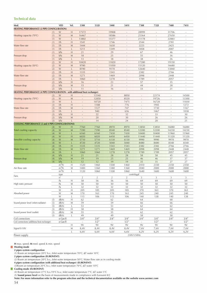
54
Technical data
Mod. VED Vel. 530I 532I 540I 541I 730I 732I 740I 741IHEATING PERFORMANCE (2 PIPE CONFIGURATION)
Heating capacity (70°C)(1) W H 17572 - 19908 - 28999 - 31706 -(1) W M 16467 - 18586 - 25364 - 27650 -(1) W L 13802 - 15377 - 21178 - 22883 -
Water flow rate(1) l/h H 1541 - 1746 - 2544 - 2781 -(1) l/h M 1444 - 1630 - 2225 - 2425 -(1) l/h L 1211 - 1349 - 1858 - 2007 -
Pressure drop(1) kPa H 21 - 29 - 67 - 46 -(1) kPa M 18 - 25 - 55 - 36 -(1) kPa L 13 - 18 - 38 - 26 -
Heating capacity (50°C)(2) W H 10420 - 11820 - 17280 - 19150 -(2) W M 9780 - 11050 - 15120 - 16680 -(2) W L 8190 - 9170 - 12640 - 13840 -
Water flow rate(2) l/h H 1335 - 1543 - 2382 - 2766 -(2) l/h M 1271 - 1469 - 2098 - 2448 -(2) l/h L 1060 - 1278 - 1789 - 2057 -
Pressure drop(2) kPa H 16 - 23 - 57 - 35 -(2) kPa M 15 - 21 - 44 - 28 -(2) kPa L 11 - 16 - 33 - 21 -
HEATING PERFORMANCE (4 PIPE CONFIGURATION - with additional heat exchanger)
Heating capacity (70°C)(3) W H - 13540 - 8850 - 22174 - 14500(3) W M - 12850 - 8520 - 19726 - 13300(3) W L - 10720 - 7475 - 16728 - 11830
Water flow rate(3) l/h H - 1188 - 776 - 1945 - 1272(3) l/h M - 1127 - 747 - 1730 - 1167(3) l/h L - 940 - 656 - 1467 - 1038
Pressure drop(3) kPa H - 22 - 32 - 33 - 30(3) kPa M - 20 - 30 - 26 - 26(3) kPa L - 14 - 24 - 20 - 21
COOLING PERFORMANCE (2 and 4 PIPE CONFIGURATIONS)
Total cooling capacity(4) W H 7760 7760 8970 8970 13850 13850 16080 16080(4) W M 7390 7390 8540 8540 12200 12200 14230 14230(4) W L 6160 6160 7430 7430 10400 10400 11960 11960
Sensible cooling capacity(4) W H 6020 6020 6450 6450 11440 11440 11320 11320(4) W M 5710 5710 6130 6130 9990 9990 9970 9970(4) W L 4720 4720 5040 5040 8480 8480 8340 8340
Water flow rate (4) l/h H 1335 1335 1543 1543 2382 2382 2766 2766(4) l/h M 1271 1271 1469 1469 2098 2098 2448 2448(4) l/h L 1060 1060 1278 1278 1789 1789 2057 2057
Pressure drop(4) kPa H 21 21 28 28 58 58 45 45(4) kPa M 19 19 25 25 46 46 37 37(4) kPa L 12 12 19 19 35 35 27 27
Air flow ratem3/h H 1520 1460 1500 1460 2410 2350 2350 2350m3/h M 1400 1360 1380 1360 2040 2000 2000 2000m3/h L 1120 1060 1100 1060 1640 1600 1600 1600
Fanstype centrifugaln° 2 2 2 2 3 3 3 3
High static pressurePa H 58 56 56 56 69 69 69 69Pa M 50 50 50 50 50 50 50 50Pa L 32 32 32 32 32 32 32 32
Absorbed powerW H 205 185 205 185 370 363 370 363W M 170 163 170 163 245 240 245 240W L 115 106 115 106 140 138 140 138
Sound power level (inlet+radiator)(5) dB(A) H 62 62 64 68(5) dB(A) M 59 59 66 66(5) dB(A) L 53 53 62 62
Sound power level (outlet)(5) dB(A) H 58 58 64 64(5) dB(A) M 55 55 62 62(5) dB(A) L 49 49 58 58
Coil connections ø Gas (F) 3/4” 3/4” 3/4” 3/4” 3/4” 3/4” 3/4” 3/4”Coil connections (additiona heat exchanger) ø Gas (F) - 1/2” - 1/2” - 1/2” - 1/2”
Signal 0-10VH 9V 9V 9V 9V 9V 9V 9V 9VM 8,4V 8,4V 8,4V 8,4V 7,6V 7,6V 7,6V 7,6VL 6,6V 6,6V 6,6V 6,6V 6,2V 6,2V 6,2V 6,2V
Power supply 230V/1/50Hz
H max. speed; M med. speed; L min. speedHeating mode2 pipes system configuration(1) Room air temperature 20°C b.s.; Inlet water temperature 70°C; ΔT water 10°C2 pipes system configuration (EUROVENT)(2) Room air temperature 20°C b.s.; Inlet water temperature 50°C; Water flow rate as in cooling mode4 pipes system configuration (with additional heat exchanger) (EUROVENT)(3)Room air temperature 20°C b.s.; Inlet water temperature 70°C; ΔT water 10°CCooling mode (EUROVENT)(4) Room air temperature 27°C b.s./19°C b.u.; Inlet water temperature 7°C; ΔT water 5°C(5) Sound power level on the basis of measurements made in compliance with Eurovent 8/2Note: For more information refer to the program selection and the technical documentation available on the website www.aermec.com
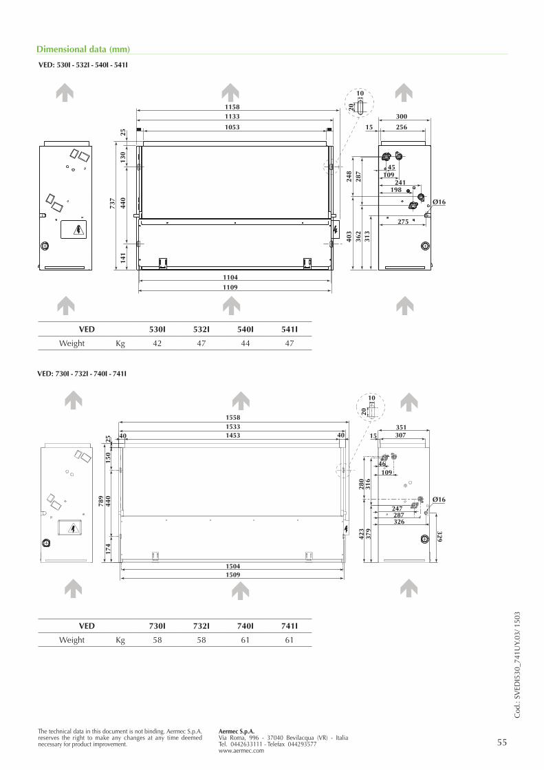
55Aermec S.p.A.Via Roma, 996 - 37040 Bevilacqua (VR) - ItaliaTel. 0442633111 - Telefax 044293577www.aermec.com
The technical data in this document is not binding. Aermec S.p.A. reserves the right to make any changes at any time deemed necessary for product improvement.
Cod
.: SV
EDI5
30_7
41U
Y.03
/ 150
3
Dimensional data (mm)
VED: 530I - 532I - 540I - 541I
VED: 730I - 732I - 740I - 741I
1133
1053
1104
440
737
141
130
25300
25615
248
287
403
362
313
45109
241198
275
Ø16
10
201158
1109
= =
1133
1053
110444
0
737
141
130
25
300
25615
248
287
403
362
313
45109
241198
275
Ø16
10
201158
1109
Ø16
15091504
789
150
440
174
25
15581533145340 40
329423
280
316
351307
109
379
15
326
247287
46
10
20
VED 530I 532I 540I 541I
Weight Kg 42 47 44 47
VED 730I 732I 740I 741I
Weight Kg 58 58 61 61
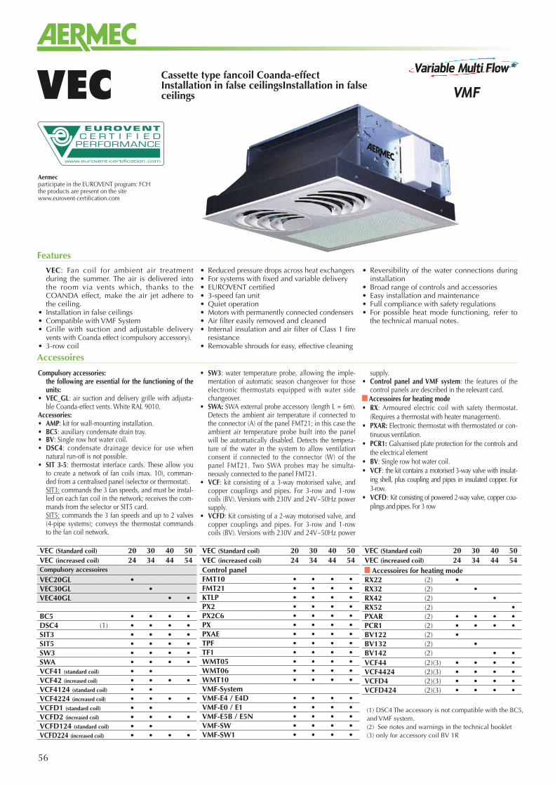
56
Cassette type fancoil Coanda-effect Installation in false ceilingsInstallation in false ceilingsVEC
Aermecparticipate in the EUROVENT program: FCHthe products are present on the sitewww.eurovent-certification.com
VEC: Fan coil for ambient air treatment during the summer. The air is delivered into the room via vents which, thanks to the COANDA effect, make the air jet adhere to the ceiling.
• Installation in false ceilings• Compatible with VMF System• Grille with suction and adjustable delivery
vents with Coanda effect (compulsory accessory).• 3-row coil
• Reduced pressure drops across heat exchangers• For systems with fixed and variable delivery• EUROVENT certified• 3-speed fan unit• Quiet operation• Motors with permanently connected condensers• Air filter easily removed and cleaned• Internal insulation and air filter of Class 1 fire
resistance• Removable shrouds for easy, effective cleaning
• Reversibility of the water connections during installation
• Broad range of controls and accessories• Easy installation and maintenance• Full compliance with safety regulations• For possible heat mode functioning, refer to
the technical manual notes.
Features
Compulsory accessories: the following are essential for the functioning of the
units:• VEC_GL: air suction and delivery grille with adjusta-
ble Coanda-effect vents. White RAL 9010.Accessories:• AMP: kit for wall-mounting installation.• BC5: auxiliary condensate drain tray.• BV: Single row hot water coil.• DSC4: condensate drainage device for use when
natural run-off is not possible. • SIT 3-5: thermostat interface cards. These allow you
to create a network of fan coils (max. 10), comman-ded from a centralised panel (selector or thermostat).
SIT3: commands the 3 fan speeds, and must be instal-led on each fan coil in the network; receives the com-mands from the selector or SIT5 card.
SIT5: commands the 3 fan speeds and up to 2 valves (4-pipe systems); conveys the thermostat commands to the fan coil network.
• SW3: water temperature probe, allowing the imple-mentation of automatic season changeover for those electronic thermostats equipped with water side changeover.
• SWA: SWA external probe accessory (length L = 6m). Detects the ambient air temperature if connected to the connector (A) of the panel FMT21; in this case the ambient air temperature probe built into the panel will be automatically disabled. Detects the tempera-ture of the water in the system to allow ventilation consent if connected to the connector (W) of the panel FMT21. Two SWA probes may be simulta-neously connected to the panel FMT21.
• VCF: kit consisting of a 3-way motorised valve, and copper couplings and pipes. For 3-row and 1-row coils (BV). Versions with 230V and 24V~50Hz power supply.
• VCFD: Kit consisting of a 2-way motorised valve, and copper couplings and pipes. For 3-row and 1-row coils (BV). Versions with 230V and 24V~50Hz power
supply.• Control panel and VMF system: the features of the
control panels are described in the relevant card. Accessoires for heating mode
• RX: Armoured electric coil with safety thermostat. (Requires a thermostat with heater management).
• PXAR: Electronic thermostat with thermostated or con-tinuous ventilation.
• PCR1: Galvanised plate protection for the controls and the electrical element
• BV: Single row hot water coil.• VCF: the kit contains a motorised 3-way valve with insulat-
ing shell, plus coupling and pipes in insulated copper. For 3-row.
• VCFD: Kit consisting of powered 2-way valve, copper cou-plings and pipes. For 3 row
Accessoires
(1) DSC4 The accessory is not compatible with the BC5, and VMF system.(2) See notes and warnings in the technical booklet(3) only for accessory coil BV 1R
VEC (Standard coil) 20 30 40 50VEC (increased coil) 24 34 44 54Compulsory accessoires
VEC20GL •VEC30GL •VEC40GL • •
BC5 • • • •DSC4 (1) • • • •SIT3 • • • •SIT5 • • • •SW3 • • • •SWA • • • •VCF41 (standard coil) • •VCF42 (increased coil) • • • •VCF4124 (standard coil) • •VCF4224 (increased coil) • • • •VCFD1 (standard coil) • •VCFD2 (increased coil) • • • •VCFD124 (standard coil) • •VCFD224 (increased coil) • • • •
VEC (Standard coil) 20 30 40 50VEC (increased coil) 24 34 44 54Control panelFMT10 • • • •FMT21 • • • •KTLP • • • •PX2 • • • •PX2C6 • • • •PX • • • •PXAE • • • •TPF • • • •TF1 • • • •WMT05 • • • •WMT06 • • • •WMT10 • • • •VMF-SystemVMF-E4 / E4D • • • •VMF-E0 / E1 • • • •VMF-E5B / E5N • • • •VMF-SW • • • •VMF-SW1 • • • •
VEC (Standard coil) 20 30 40 50VEC (increased coil) 24 34 44 54
Accessoires for heating modeRX22 (2) •RX32 (2) •RX42 (2) •RX52 (2) •PXAR (2) • • • •PCR1 (2) • • • •BV122 (2) •BV132 (2) •BV142 (2) • •VCF44 (2)(3) • • • •VCF4424 (2)(3) • • • •VCFD4 (2)(3) • • • •VCFD424 (2)(3) • • • •
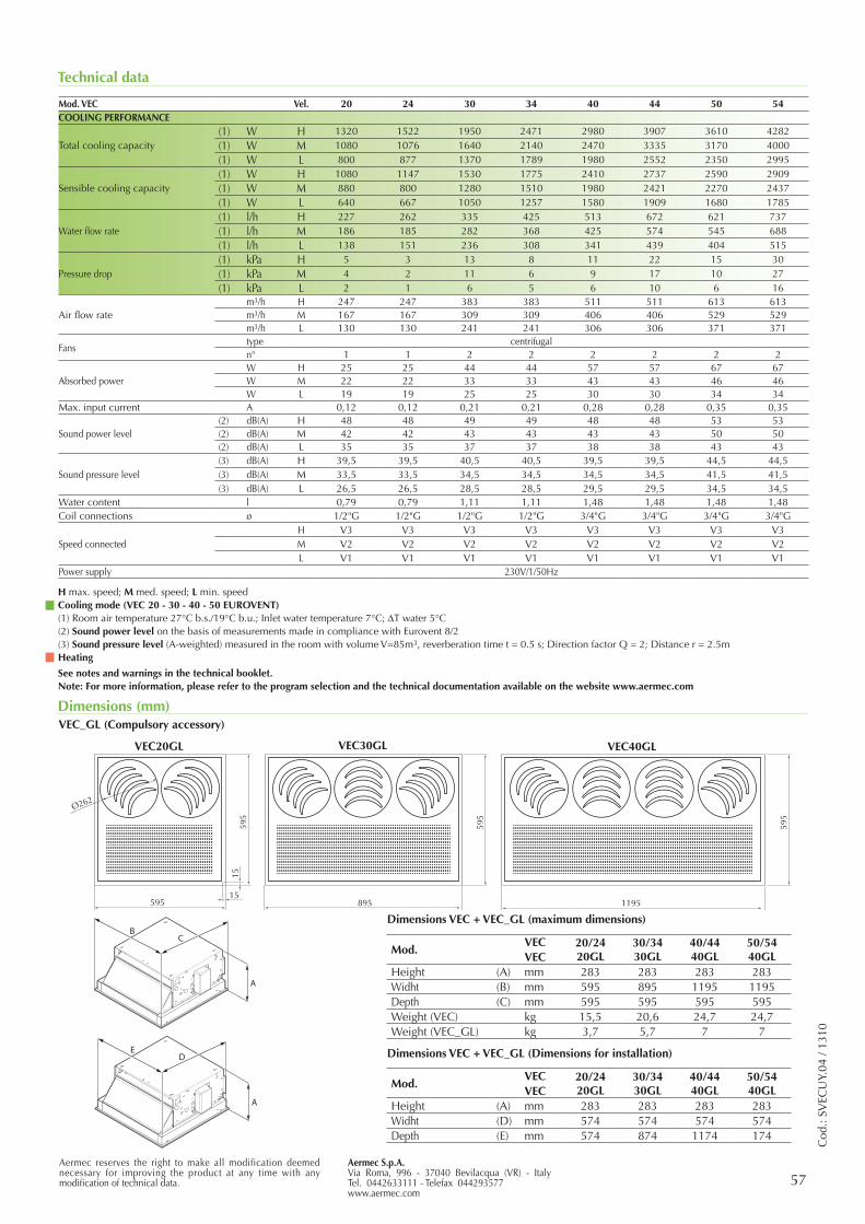
Aermec S.p.A.Via Roma, 996 - 37040 Bevilacqua (VR) - ItalyTel. 0442633111 - Telefax 044293577www.aermec.com
57Aermec reserves the right to make all modification deemed necessary for improving the product at any time with any modification of technical data.
Cod
.: SV
ECU
Y.04
/ 13
10
Technical data
Mod. VEC Vel. 20 24 30 34 40 44 50 54COOLING PERFORMANCE
Total cooling capacity(1) W H 1320 1522 1950 2471 2980 3907 3610 4282(1) W M 1080 1076 1640 2140 2470 3335 3170 4000(1) W L 800 877 1370 1789 1980 2552 2350 2995
Sensible cooling capacity(1) W H 1080 1147 1530 1775 2410 2737 2590 2909(1) W M 880 800 1280 1510 1980 2421 2270 2437(1) W L 640 667 1050 1257 1580 1909 1680 1785
Water flow rate (1) l/h H 227 262 335 425 513 672 621 737(1) l/h M 186 185 282 368 425 574 545 688(1) l/h L 138 151 236 308 341 439 404 515
Pressure drop(1) kPa H 5 3 13 8 11 22 15 30(1) kPa M 4 2 11 6 9 17 10 27(1) kPa L 2 1 6 5 6 10 6 16
Air flow ratem3/h H 247 247 383 383 511 511 613 613m3/h M 167 167 309 309 406 406 529 529m3/h L 130 130 241 241 306 306 371 371
Fanstype centrifugaln° 1 1 2 2 2 2 2 2
Absorbed powerW H 25 25 44 44 57 57 67 67W M 22 22 33 33 43 43 46 46W L 19 19 25 25 30 30 34 34
Max. input current A 0,12 0,12 0,21 0,21 0,28 0,28 0,35 0,35
Sound power level(2) dB(A) H 48 48 49 49 48 48 53 53(2) dB(A) M 42 42 43 43 43 43 50 50(2) dB(A) L 35 35 37 37 38 38 43 43
Sound pressure level(3) dB(A) H 39,5 39,5 40,5 40,5 39,5 39,5 44,5 44,5(3) dB(A) M 33,5 33,5 34,5 34,5 34,5 34,5 41,5 41,5(3) dB(A) L 26,5 26,5 28,5 28,5 29,5 29,5 34,5 34,5
Water content l 0,79 0,79 1,11 1,11 1,48 1,48 1,48 1,48Coil connections ø 1/2"G 1/2"G 1/2"G 1/2"G 3/4"G 3/4"G 3/4"G 3/4"G
Speed connectedH V3 V3 V3 V3 V3 V3 V3 V3M V2 V2 V2 V2 V2 V2 V2 V2L V1 V1 V1 V1 V1 V1 V1 V1
Power supply 230V/1/50Hz
H max. speed; M med. speed; L min. speedCooling mode (VEC 20 - 30 - 40 - 50 EUROVENT)(1) Room air temperature 27°C b.s./19°C b.u.; Inlet water temperature 7°C; DT water 5°C(2) Sound power level on the basis of measurements made in compliance with Eurovent 8/2(3) Sound pressure level (A-weighted) measured in the room with volume V=85m3, reverberation time t = 0.5 s; Direction factor Q = 2; Distance r = 2.5mHeating
See notes and warnings in the technical booklet.Note: For more information, please refer to the program selection and the technical documentation available on the website www.aermec.com
Dimensions (mm)
595
1195895
595
Ø262
59515
1559
5
VEC20GL VEC40GLVEC30GL
A
ED
A
BC
Mod.VEC 20/24
20GL30/3430GL
40/4440GL
50/5440GLVEC
Height (A) mm 283 283 283 283Widht (D) mm 574 574 574 574Depth (E) mm 574 874 1174 174
Mod.VEC 20/24
20GL30/3430GL
40/4440GL
50/5440GLVEC
Height (A) mm 283 283 283 283Widht (B) mm 595 895 1195 1195Depth (C) mm 595 595 595 595Weight (VEC) kg 15,5 20,6 24,7 24,7Weight (VEC_GL) kg 3,7 5,7 7 7
Dimensions VEC + VEC_GL (maximum dimensions)
VEC_GL (Compulsory accessory)
Dimensions VEC + VEC_GL (Dimensions for installation)
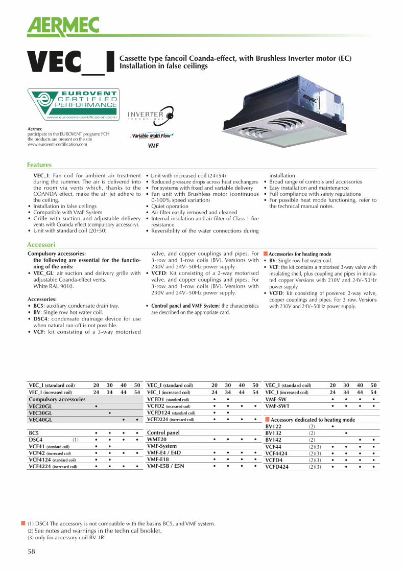
58
Cassette type fancoil Coanda-effect, with Brushless Inverter motor (EC)Installation in false ceilingsVEC_I
Aermecparticipate in the EUROVENT program: FCHthe products are present on the sitewww.eurovent-certification.com
VEC_I: Fan coil for ambient air treatment during the summer. The air is delivered into the room via vents which, thanks to the COANDA effect, make the air jet adhere to the ceiling.
• Installation in false ceilings• Compatible with VMF System• Grille with suction and adjustable delivery
vents with Coanda effect (compulsory accessory).• Unit with standard coil (20÷50)
• Unit with increased coil (24÷54) • Reduced pressure drops across heat exchangers• For systems with fixed and variable delivery• Fan unit with Brushless motor (continuous
0-100% speed variation)• Quiet operation• Air filter easily removed and cleaned• Internal insulation and air filter of Class 1 fire
resistance• Reversibility of the water connections during
installation• Broad range of controls and accessories• Easy installation and maintenance• Full compliance with safety regulations• For possible heat mode functioning, refer to
the technical manual notes.
Features
Compulsory accessories: the following are essential for the functio-
ning of the units:• VEC_GL: air suction and delivery grille with
adjustable Coanda-effect vents. White RAL 9010.
Accessories:• BC5: auxiliary condensate drain tray.• BV: Single row hot water coil.• DSC4: condensate drainage device for use
when natural run-off is not possible. • VCF: kit consisting of a 3-way motorised
valve, and copper couplings and pipes. For 3-row and 1-row coils (BV). Versions with 230V and 24V~50Hz power supply.
• VCFD: Kit consisting of a 2-way motorised valve, and copper couplings and pipes. For 3-row and 1-row coils (BV). Versions with 230V and 24V~50Hz power supply.
• Control panel and VMF System: the characteristics are described on the appropriate card.
Accessories for heating mode• BV: Single row hot water coil.• VCF: the kit contains a motorised 3-way valve with
insulating shell, plus coupling and pipes in insula-ted copper Versions with 230V and 24V~50Hz power supply.
• VCFD: Kit consisting of powered 2-way valve, copper couplings and pipes. For 3 row. Versions with 230V and 24V~50Hz power supply.
Accessori
(1) DSC4 The accessory is not compatible with the basins BC5, and VMF system.(2) See notes and warnings in the technical booklet.(3) only for accessory coil BV 1R
VEC_I (standard coil) 20 30 40 50VEC_I (increased coil) 24 34 44 54Compulsory accessoriesVEC20GL •VEC30GL •VEC40GL • •
BC5 • • • •DSC4 (1) • • • •VCF41 (standard coil) • •VCF42 (increased coil) • • • •VCF4124 (standard coil) • •VCF4224 (increased coil) • • • •
VEC_I (standard coil) 20 30 40 50VEC_I (increased coil) 24 34 44 54VCFD1 (standard coil) • •VCFD2 (increased coil) • • • •VCFD124 (standard coil) • •VCFD224 (increased coil) • • • •
Control panelWMT20 • • • •VMF-SystemVMF-E4 / E4D • • • •VMF-E18 • • • •VMF-E5B / E5N • • • •
VEC_I (standard coil) 20 30 40 50VEC_I (increased coil) 24 34 44 54VMF-SW • • • •VMF-SW1 • • • •
Accessory dedicated to heating modeBV122 (2) •BV132 (2) •BV142 (2) • •VCF44 (2)(3) • • • •VCF4424 (2)(3) • • • •VCFD4 (2)(3) • • • •VCFD424 (2)(3) • • • •
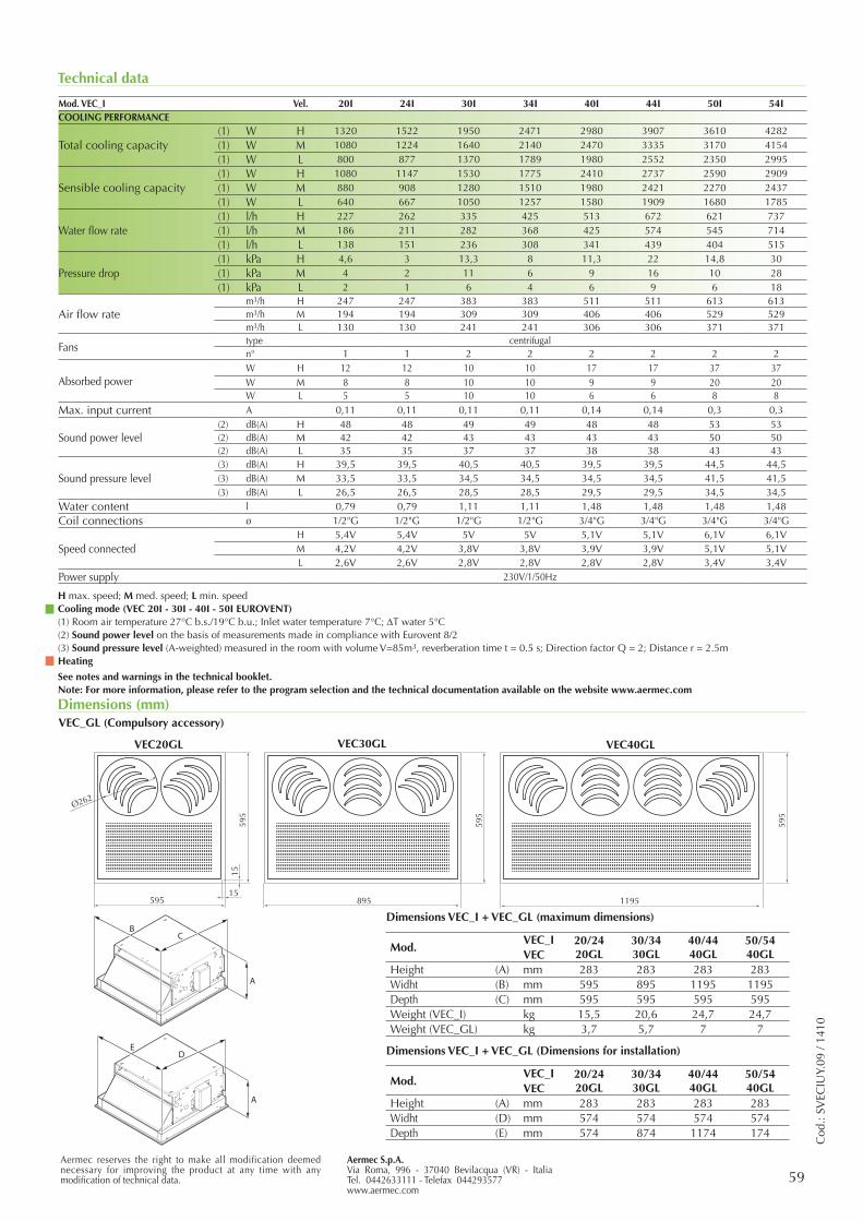
59Aermec S.p.A.Via Roma, 996 - 37040 Bevilacqua (VR) - ItaliaTel. 0442633111 - Telefax 044293577www.aermec.com
Aermec reserves the right to make all modification deemed necessary for improving the product at any time with any modification of technical data.
Cod
.: SV
ECIU
Y.09
/ 14
10
Technical data
Dimensions (mm)
595
1195895
595
Ø262
59515
1559
5
VEC20GL VEC40GLVEC30GL
A
ED
A
BC
Mod.VEC_I 20/24
20GL30/3430GL
40/4440GL
50/5440GLVEC
Height (A) mm 283 283 283 283Widht (D) mm 574 574 574 574Depth (E) mm 574 874 1174 174
Mod.VEC_I 20/24
20GL30/3430GL
40/4440GL
50/5440GLVEC
Height (A) mm 283 283 283 283Widht (B) mm 595 895 1195 1195Depth (C) mm 595 595 595 595Weight (VEC_I) kg 15,5 20,6 24,7 24,7Weight (VEC_GL) kg 3,7 5,7 7 7
Dimensions VEC_I + VEC_GL (maximum dimensions)
VEC_GL (Compulsory accessory)
Dimensions VEC_I + VEC_GL (Dimensions for installation)
Mod. VEC_I Vel. 20I 24I 30I 34I 40I 44I 50I 54ICOOLING PERFORMANCE
Total cooling capacity(1) W H 1320 1522 1950 2471 2980 3907 3610 4282(1) W M 1080 1224 1640 2140 2470 3335 3170 4154(1) W L 800 877 1370 1789 1980 2552 2350 2995
Sensible cooling capacity(1) W H 1080 1147 1530 1775 2410 2737 2590 2909(1) W M 880 908 1280 1510 1980 2421 2270 2437(1) W L 640 667 1050 1257 1580 1909 1680 1785
Water flow rate (1) l/h H 227 262 335 425 513 672 621 737(1) l/h M 186 211 282 368 425 574 545 714(1) l/h L 138 151 236 308 341 439 404 515
Pressure drop(1) kPa H 4,6 3 13,3 8 11,3 22 14,8 30(1) kPa M 4 2 11 6 9 16 10 28(1) kPa L 2 1 6 4 6 9 6 18
Air flow ratem3/h H 247 247 383 383 511 511 613 613m3/h M 194 194 309 309 406 406 529 529m3/h L 130 130 241 241 306 306 371 371
Fanstype centrifugaln° 1 1 2 2 2 2 2 2
Absorbed powerW H 12 12 10 10 17 17 37 37W M 8 8 10 10 9 9 20 20W L 5 5 10 10 6 6 8 8
Max. input current A 0,11 0,11 0,11 0,11 0,14 0,14 0,3 0,3
Sound power level(2) dB(A) H 48 48 49 49 48 48 53 53(2) dB(A) M 42 42 43 43 43 43 50 50(2) dB(A) L 35 35 37 37 38 38 43 43
Sound pressure level(3) dB(A) H 39,5 39,5 40,5 40,5 39,5 39,5 44,5 44,5(3) dB(A) M 33,5 33,5 34,5 34,5 34,5 34,5 41,5 41,5(3) dB(A) L 26,5 26,5 28,5 28,5 29,5 29,5 34,5 34,5
Water content l 0,79 0,79 1,11 1,11 1,48 1,48 1,48 1,48Coil connections ø 1/2"G 1/2"G 1/2"G 1/2"G 3/4"G 3/4"G 3/4"G 3/4"G
Speed connectedH 5,4V 5,4V 5V 5V 5,1V 5,1V 6,1V 6,1VM 4,2V 4,2V 3,8V 3,8V 3,9V 3,9V 5,1V 5,1VL 2,6V 2,6V 2,8V 2,8V 2,8V 2,8V 3,4V 3,4V
Power supply 230V/1/50Hz
H max. speed; M med. speed; L min. speedCooling mode (VEC 20I - 30I - 40I - 50I EUROVENT)(1) Room air temperature 27°C b.s./19°C b.u.; Inlet water temperature 7°C; DT water 5°C(2) Sound power level on the basis of measurements made in compliance with Eurovent 8/2(3) Sound pressure level (A-weighted) measured in the room with volume V=85m3, reverberation time t = 0.5 s; Direction factor Q = 2; Distance r = 2.5mHeating
See notes and warnings in the technical booklet.Note: For more information, please refer to the program selection and the technical documentation available on the website www.aermec.com
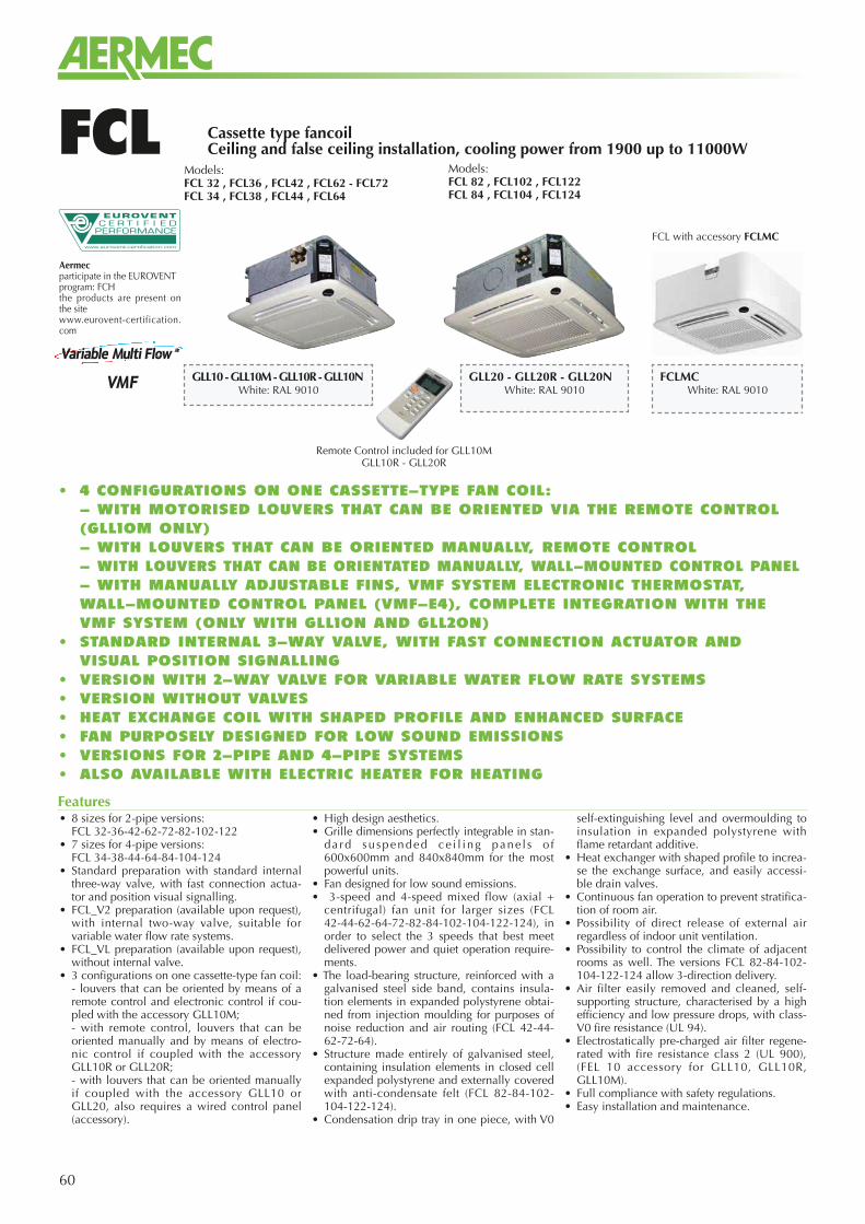
60
Aermecparticipate in the EUROVENTprogram: FCHthe products are present on the sitewww.eurovent-certification.com
Cassette type fancoilCeiling and false ceiling installation, cooling power from 1900 up to 11000WFCL
Remote Control included for GLL10MGLL10R - GLL20R
GLL10 - GLL10M - GLL10R - GLL10N White: RAL 9010
Models:FCL 32 , FCL36 , FCL42 , FCL62 - FCL72 FCL 34 , FCL38 , FCL44 , FCL64
Models:FCL 82 , FCL102 , FCL122 FCL 84 , FCL104 , FCL124
GLL20 - GLL20R - GLL20NWhite: RAL 9010
FCLMCWhite: RAL 9010
FCL with accessory FCLMC
• 8 sizes for 2-pipe versions: FCL 32-36-42-62-72-82-102-122• 7 sizes for 4-pipe versions: FCL 34-38-44-64-84-104-124• Standard preparation with standard internal
three-way valve, with fast connection actua-tor and position visual signalling.
• FCL_V2 preparation (available upon request), with internal two-way valve, suitable for variable water flow rate systems.
• FCL_VL preparation (available upon request), without internal valve.
• 3 configurations on one cassette-type fan coil: - louvers that can be oriented by means of a
remote control and electronic control if cou-pled with the accessory GLL10M;
- with remote control, louvers that can be oriented manually and by means of electro-nic control if coupled with the accessory GLL10R or GLL20R;
- with louvers that can be oriented manually if coupled with the accessory GLL10 or GLL20, also requires a wired control panel (accessory).
• High design aesthetics.• Grille dimensions perfectly integrable in stan-
da rd suspended ce i l ing pane l s o f 600x600mm and 840x840mm for the most powerful units.
• Fan designed for low sound emissions.• 3-speed and 4-speed mixed flow (axial +
centrifugal) fan unit for larger sizes (FCL 42-44-62-64-72-82-84-102-104-122-124), in order to select the 3 speeds that best meet delivered power and quiet operation require-ments.
• The load-bearing structure, reinforced with a galvanised steel side band, contains insula-tion elements in expanded polystyrene obtai-ned from injection moulding for purposes of noise reduction and air routing (FCL 42-44-62-72-64).
• Structure made entirely of galvanised steel, containing insulation elements in closed cell expanded polystyrene and externally covered with anti-condensate felt (FCL 82-84-102-104-122-124).
• Condensation drip tray in one piece, with V0
self-extinguishing level and overmoulding to insulation in expanded polystyrene with flame retardant additive.
• Heat exchanger with shaped profile to increa-se the exchange surface, and easily accessi-ble drain valves.
• Continuous fan operation to prevent stratifica-tion of room air.
• Possibility of direct release of external air regardless of indoor unit ventilation.
• Possibility to control the climate of adjacent rooms as well. The versions FCL 82-84-102-104-122-124 allow 3-direction delivery.
• Air filter easily removed and cleaned, self-supporting structure, characterised by a high efficiency and low pressure drops, with class-V0 fire resistance (UL 94).
• Electrostatically pre-charged air filter regene-rated with fire resistance class 2 (UL 900), (FEL 10 accessory for GLL10, GLL10R, GLL10M).
• Full compliance with safety regulations.• Easy installation and maintenance.
Features
• 4 CONFIGURATIONS ON ONE CASSETTE-TYPE FAN COIL: - WITH MOTORISED LOUVERS THAT CAN BE ORIENTED VIA THE REMOTE CONTROL
(GLL10M ONLY) - WITH LOUVERS THAT CAN BE ORIENTED MANUALLY, REMOTE CONTROL - WITH LOUVERS THAT CAN BE ORIENTATED MANUALLY, WALL-MOUNTED CONTROL PANEL - WITH MANUALLY ADJUSTABLE FINS, VMF SYSTEM ELECTRONIC THERMOSTAT,
WALL-MOUNTED CONTROL PANEL (VMF-E4), COMPLETE INTEGRATION WITH THE VMF SYSTEM (ONLY WITH GLL10N AND GLL20N)
• STANDARD INTERNAL 3-WAY VALVE, WITH FAST CONNECTION ACTUATOR AND VISUAL POSITION SIGNALLING
• VERSION WITH 2-WAY VALVE FOR VARIABLE WATER FLOW RATE SYSTEMS• VERSION WITHOUT VALVES• HEAT EXCHANGE COIL WITH SHAPED PROFILE AND ENHANCED SURFACE• FAN PURPOSELY DESIGNED FOR LOW SOUND EMISSIONS• VERSIONS FOR 2-PIPE AND 4-PIPE SYSTEMS• ALSO AVAILABLE WITH ELECTRIC HEATER FOR HEATING
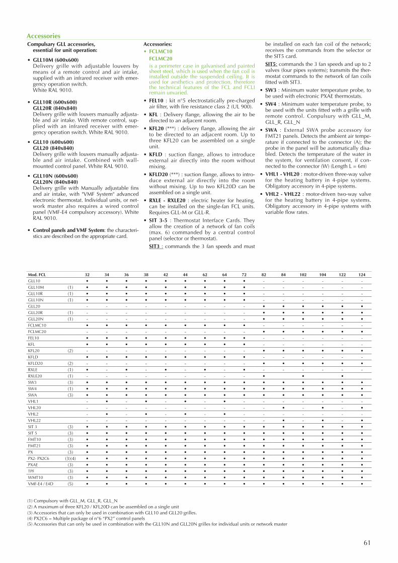
61
Compulsary GLL accessories, essential for unit operation:
• GLL10M (600x600) Delivery grille with adjustable louvers by
means of a remote control and air intake, supplied with an infrared receiver with emer-gency operation switch.
White RAL 9010.
• GLL10R (600x600) GLL20R (840x840) Delivery grille with louvers manually adjusta-
ble and air intake. With remote control, sup-plied with an infrared receiver with emer-gency operation switch. White RAL 9010.
• GLL10 (600x600) GLL20 (840x840) Delivery grille with louvers manually adjusta-
ble and air intake. Combined with wall-mounted control panel. White RAL 9010.
• GLL10N (600x600) GLL20N (840x840) Delivery grille with Manually adjustable fins
and air intake, with "VMF System" advanced electronic thermostat. Individual units, or net-work master also requires a wired control panel (VMF-E4 compulsory accessory). White RAL 9010.
• Control panels and VMF System: the characteri-stics are described on the appropriate card.
Accessories:• FCLMC10 FCLMC20 is a perimeter case in galvanised and painted
sheet steel, which is used when the fan coil is installed outside the suspended ceiling. It is used for aesthetics and protection, therefore the technical features of the FCL and FCLI remain unvaried.
• FEL10 : kit n°5 electrostatically pre-charged air filter, with fire resistance class 2 (UL 900).
• KFL : Delivery flange, allowing the air to be directed to an adjacent room.
• KFL20 (***) : delivery flange, allowing the air to be directed to an adjacent room. Up to three KFL20 can be assembled on a single unit.
• KFLD : suction flange, allows to introduce external air directly into the room without mixing.
• KFLD20 (***) : suction flange, allows to intro-duce external air directly into the room without mixing. Up to two KFL20D can be assembled on a single unit.
• RXLE - RXLE20 : electric heater for heating, can be installed on the single-fan FCL units. Requires GLL-M or GLL-R.
• SIT 3-5 : Thermostat Interface Cards. They allow the creation of a network of fan coils (max. 6) commanded by a central control panel (selector or thermostat).
SIT3 : commands the 3 fan speeds and must
be installed on each fan coil of the network; receives the commands from the selector or the SIT5 card.
SIT5: commands the 3 fan speeds and up to 2 valves (four pipes systems); transmits the ther-mostat commands to the network of fan coils fitted with SIT3.
• SW3 : Minimum water temperature probe, to be used with electronic PXAE thermostats.
• SW4 : Minimum water temperature probe, to be used with the units fitted with a grille with remote control. Conpulsury with GLL_M, GLL_R, GLL_N
• SWA : External SWA probe accessory for FMT21 panels. Detects the ambient air tempe-rature if connected to the connector (A); the probe in the panel will be automatically disa-bled. Detects the temperature of the water in the system, for ventilation consent, if con-nected to the connector (W) (Length L = 6m)
• VHL1 - VHL20 : motor-driven three-way valve for the heating battery in 4-pipe systems. Obligatory accessory in 4-pipe systems.
• VHL2 - VHL22 : motor-driven two-way valve for the heating battery in 4-pipe systems. Obligatory accessory in 4-pipe systems with variable flow rates.
Accessories
(1) Compulsory with GLL_M, GLL_R, GLL_N(2) A maximum of three KFL20 / KFL20D can be assembled on a single unit (3) Accessories that can only be used in combination with GLL10 and GLL20 grilles.(4) PX2C6 = Multiple package of n°6 “PX2” control panels (5) Accessories that can only be used in combination with the GLL10N and GLL20N grilles for individual units or network master
Mod. FCL 32 34 36 38 42 44 62 64 72 82 84 102 104 122 124
GLL10 • • • • • • • • • - - - - - -GLL10M (1) • • • • • • • • • - - - - - -GLL10R (1) • • • • • • • • • - - - - - -GLL10N (1) • • • • • • • • • - - - - - -GLL20 - - - - - - - - - • • • • • •GLL20R (1) - - - - - - - - - • • • • • •GLL20N (1) - - - - - - - - - • • • • • •FCLMC10 • • • • • • • • • - - - - - -FCLMC20 - - - - - - - - - • • • • • •FEL10 • • • • • • • • • - - - - - -KFL • • • • • • • • • - - - - - -KFL20 (2) - - - - - - - - - • • • • • •KFLD • • • • • • • • • - - - - - -KFLD20 (2) - - - - - - - - - • • • • • •RXLE (1) • - • - • - • - • - - - - - -RXLE20 (1) - - - - - - - - - • • •SW3 (3) • • • • • • • • • • • • • • •SW4 (1) • • • • • • • • • • • • • • •SWA (3) • • • • • • • • • • • • • • •VHL1 - • - • - • - • - - - - - - -VHL20 - - - - - - - - - - • - • - •VHL2 - • - • - • - • - - - - - - -VHL22 - - - - - - - - - - • - • - •SIT 3 (3) • • • • • • • • • • • • • • •SIT 5 (3) • • • • • • • • • • • • • • •FMT10 (3) • • • • • • • • • • • • • • •FMT21 (3) • • • • • • • • • • • • • • •PX (3) • • • • • • • • • • • • • • •PX2- PX2C6 (3)(4) • • • • • • • • • • • • • • •PXAE (3) • • • • • • • • • • • • • • •TPF (3) • • • • • • • • • • • • • • •WMT10 (3) • • • • • • • • • • • • • • •VMF-E4 / E4D (5) • • • • • • • • • • • • • • •
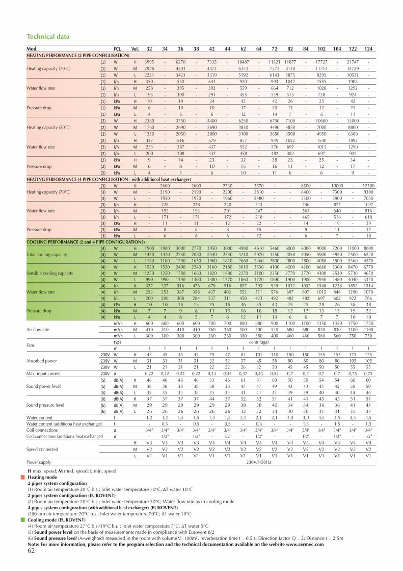
62
Technical data
H max. speed; M med. speed; L min. speedHeating mode2 pipes system configuration(1) Room air temperature 20°C b.s.; Inlet water temperature 70°C; ΔT water 10°C2 pipes system configuration (EUROVENT)(2) Room air temperature 20°C b.s.; Inlet water temperature 50°C; Water flow rate as in cooling mode4 pipes system configuration (with additional heat exchanger) (EUROVENT)(3)Room air temperature 20°C b.s.; Inlet water temperature 70°C; ΔT water 10°CCooling mode (EUROVENT)(4) Room air temperature 27°C b.s./19°C b.u.; Inlet water temperature 7°C; DT water 5°C(5) Sound power level on the basis of measurements made in compliance with Eurovent 8/2(6) Sound pressure level (A-weighted) measured in the room with volume V=100m3, reverberation time t = 0.5 s; Direction factor Q = 2; Distance r = 2.5mNote: For more information, please refer to the program selection and the technical documentation available on the website www.aermec.com
Mod. FCL Vel. 32 34 36 38 42 44 62 64 72 82 84 102 104 122 124HEATING PERFORMANCE (2 PIPE CONFIGURATION)
Heating capacity (70°C)(1) W H 3995 - 6270 - 7335 - 10487 - 11321 11877 - 17727 - 21747 -(1) W M 2946 - 4503 - 4473 - 6373 - 7571 8118 - 11714 - 14729 -(1) W L 2221 - 3423 - 3319 - 5192 - 6143 5875 - 8295 - 10531 -
Water flow rate(1) l/h H 350 - 550 - 643 - 920 - 993 1042 - 1555 - 1908 -(1) l/h M 258 - 395 - 392 - 559 - 664 712 - 1028 - 1292 -(1) l/h L 195 - 300 - 291 - 455 - 539 515 - 728 - 924 -
Pressure drop(1) kPa H 10 - 19 - 24 - 42 - 42 26 - 25 - 42 -(1) kPa M 6 - 10 - 10 - 17 - 20 13 - 12 - 21 -(1) kPa L 4 - 6 - 6 - 12 - 14 7 - 6 - 11 -
Heating capacity (50°C)(2) W H 2380 - 3750 - 4400 - 6250 - 6750 7100 - 10600 - 13000 -(2) W M 1760 - 2690 - 2690 - 3830 - 4490 4850 - 7000 - 8800 -(2) W L 1330 - 2050 - 2000 - 3100 - 3650 3500 - 4950 - 6300 -
Water flow rate(2) l/h H 327 - 516 - 679 - 857 - 939 1032 - 1548 - 1892 -(2) l/h M 253 - 387 - 437 - 552 - 576 697 - 1015 - 1290 -(2) l/h L 200 - 308 - 337 - 458 - 482 482 - 697 - 922 -
Pressure drop(2) kPa H 9 - 14 - 23 - 32 - 38 23 - 25 - 34 -(2) kPa M 6 - 8 - 10 - 15 - 16 11 - 12 - 17 -(2) kPa L 4 - 5 - 6 - 10 - 11 6 - 6 - 9 -
HEATING PERFORMANCE (4 PIPE CONFIGURATION - with additional heat exchanger)
Heating capacity (70°C)(3) W H - 2600 - 2600 - 2730 - 3570 - - 8500 - 10000 - 12500(3) W M - 2190 - 2190 - 2290 - 2810 - - 6400 - 7300 - 9300(3) W L - 1950 - 1950 - 1960 - 2480 - - 5300 - 5900 - 7050
Water flow rate(3) l/h H - 228 - 228 - 240 - 313 - - 746 - 877 - 1097(3) l/h M - 192 - 192 - 201 - 247 - - 561 - 640 - 816(3) l/h L - 171 - 171 - 172 - 218 - - 465 - 518 - 618
Pressure drop(3) kPa H - 11 - 11 - 12 - 22 - - 14 - 19 - 29(3) kPa M - 8 - 8 - 8 - 15 - - 9 - 11 - 17(3) kPa L - 6 - 6 - 6 - 12 - - 6 - 7 - 10
COOLING PERFORMANCE (2 and 4 PIPE CONFIGURATIONS)
Total cooling capacity(4) W H 1900 1900 3000 2770 3950 3000 4980 4610 5460 6000 6000 9000 7200 11000 8800(4) W M 1470 1470 2250 2080 2540 2340 3210 2970 3350 4050 4050 5900 4920 7500 6220(4) W L 1160 1160 1790 1650 1960 1810 2660 2460 2800 2800 2800 4050 3500 5360 4570
Sensible cooling capacity(4) W H 1520 1520 2400 2240 3160 2180 3810 3530 4100 4200 4200 6660 5300 8470 6770(4) W M 1250 1250 1780 1660 1820 1680 2270 2100 2350 2770 2770 4300 3530 5730 4670(4) W L 990 990 1390 1300 1380 1270 1860 1720 1890 1900 1900 2940 2480 4040 3370
Water flow rate (4) l/h H 327 327 516 476 679 516 857 793 939 1032 1032 1548 1238 1892 1514(4) l/h M 253 253 387 358 437 402 552 511 576 697 697 1015 846 1290 1070(4) l/h L 200 200 308 284 337 311 458 423 482 482 482 697 602 922 786
Pressure drop(4) kPa H 10 10 15 13 25 15 36 35 43 25 25 28 26 38 38(4) kPa M 7 7 9 8 11 10 16 16 18 12 12 13 13 19 22(4) kPa L 4 4 6 5 7 6 12 11 13 6 6 7 7 10 10
Air flow ratem3/h H 600 600 600 600 700 700 880 880 900 1100 1100 1350 1350 1750 1750m3/h M 410 410 410 410 360 360 500 500 520 680 680 830 830 1100 1100m3/h L 300 300 300 300 260 260 380 380 400 460 460 560 560 750 750
Fanstype centrifugaln° 1 1 1 1 1 1 1 1 1 1 1 1 1 1 1
Absorbed power230V W H 45 45 45 45 75 47 83 101 110 150 150 155 155 175 175230V W M 31 31 31 31 32 32 37 45 58 80 80 80 80 105 105230V W L 21 21 21 21 22 22 26 32 50 45 45 50 50 55 55
Max. input current 230V A 0,22 0,22 0,22 0,22 0,33 0,33 0,37 0,45 0,52 0,7 0,7 0,7 0,7 0,75 0,75
Sound power level(5) dB(A) H 46 46 46 46 53 46 61 61 60 50 50 54 54 60 60(5) dB(A) M 38 38 38 38 38 38 47 47 49 43 43 45 45 50 50(5) dB(A) L 35 35 35 35 35 35 41 41 43 39 39 40 40 44 46
Sound pressure level(6) dB(A) H 37 37 37 37 44 37 52 52 51 41 41 45 45 51 51(6) dB(A) M 29 29 29 29 29 29 38 38 40 34 34 36 36 41 41(6) dB(A) L 26 26 26 26 26 26 32 32 34 30 30 31 31 35 37
Water content l 1,2 1,2 1,5 1,5 1,5 1,5 2,1 2,1 2,1 3,0 3,0 4,5 4,5 4,5 4,5Water content (additiona heat exchanger) l - 0,3 - 0,5 - 0,5 - 0,6 - - 1,5 - 1,5 - 1,5Coil connections ø 3/4" 3/4" 3/4" 3/4" 3/4" 3/4" 3/4" 3/4" 3/4" 3/4" 3/4" 3/4" 3/4" 3/4" 3/4"Coil connections (additiona heat exchanger) ø - 1/2" - 1/2" - 1/2" - 1/2" - - 1/2" - 1/2" - 1/2"
Speed connectedH V3 V3 V3 V3 V4 V4 V4 V4 V4 V4 V4 V4 V4 V4 V4M V2 V2 V2 V2 V2 V2 V2 V2 V2 V2 V2 V2 V2 V2 V2L V1 V1 V1 V1 V1 V1 V1 V1 V1 V1 V1 V1 V1 V1 V1
Power supply 230V/1/50Hz
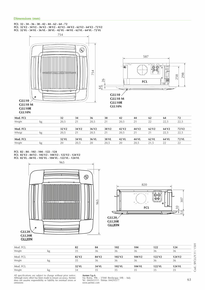
Aermec S.p.A.Via Roma, 996 - 37040 Bevilacqua (VR) - ItalyTel. 0442633111 - Telefax 044293577www.aermec.com
63All specifications are subject to change without prior notice. Although every effort has been made to ensure accuracy, Aermec does not assume responsibility or liability for eventual errors or omissions
Dimensions (mm)
FCL 32 - 34 - 36 - 38 - 42 - 44 - 62 - 64 - 72FCL 32 V2 - 34 V2 - 36 V2 - 38 V2 - 42 V2 - 44 V2 - 62 V2 - 64 V2 - 72 V2FCL 32 VL - 34 VL - 36 VL - 38 VL - 42 VL - 44 VL - 62 VL - 64 VL - 72 VL
GLL20N
GLL20N
FCL 82 - 84 - 102 - 104 - 122 - 124 FCL 82 V2 - 84 V2 - 102 V2 - 104 V2 - 122 V2 - 124 V2 FCL 82 VL - 84 VL - 102 VL - 104 VL - 122 VL - 124 VL
Cod
.: SF
CLU
Y.11
/ 15
01
Mod. FCL 32 34 36 38 42 44 62 64 72Weight kg 20,5 21 20,5 21 20,5 21 22 22,5 22,5
Mod. FCL 82 84 102 104 122 124Weight kg 35 36 36 36 36 36
Mod. FCL 32 V2 34 V2 36 V2 38 V2 42 V2 44 V2 62 V2 64 V2 72 V2Wheigt kg 20,5 21 20,5 21 20,5 21 21 22,5 22,5
Mod. FCL 82 V2 84 V2 102 V2 104 V2 122 V2 124 V2Weight kg 35 36 36 36 36 36
Mod. FCL 32 VL 34 VL 36 VL 38 VL 42 VL 44 VL 62 VL 64 VL 72 VLWeight kg 20 20,5 20 20,5 20 20,5 21,5 22 22
Mod. FCL 32 VL 34 VL 102 VL 104 VL 122 VL 124 VLWeight kg 34 35 35 35 35 35
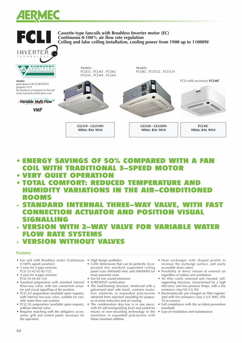
64
Cassette-type fancoils with Brushless Inverter motor (EC)Continuous 0-100% air flow rate regulationCeiling and false ceiling installation, cooling power from 1900 up to 11000WFCLI
GLLI10 - GLLI10NWhite: RAL 9010
Models:FCLI32 , FCLI42 , FCLI62 FCLI34 , FCLI44 , FCLI64
GLLI20 - GLLI20NWhite: RAL 9010
FCLMCWhite: RAL 9010
Models:FCLI82 , FCLI122 , FCLI124
FCLI with accessory FCLMC
• Fan unit with Brushless motor (Continuous 0-100% speed variation);
• 5 sizes for 2-pipe versions: FCLI 32-42-62-82-122• 4 sizes for 4-pipe versions: FCLI 34-44-64-124• Standard preparation with standard internal
three-way valve, with fast connection actua-tor and visual signalling of the position
• FCLI_V2 preparation (available upon request), with internal two-way valve, suitable for vari-able water flow rate systems
• FCLI_VL preparation (available upon request), without internal valve
• Requires matching with the obligatory acces-sories, grill and control panel, necessary for the operation
• High design aesthetics• Grille dimensions that can be perfectly incor-
porated into standard suspended ceiling panel sizes (600x600 mm) and (840X840) for more powerful units.
• Fan for low sound emissions• EUROVENT certification• The load-bearing structure, reinforced with a
galvanised steel side band, contains insula-tion elements in expanded polystyrene obtained from injection moulding for purpos-es of noise reduction and air routing
• The condensation drip tray is in one piece, with V0 self-extinguishing level and joined by means of over-moulding technology to the insulation in expanded polystyrene with flame retardant additive
• Heat exchanger with shaped profile to increase the exchange surface, and easily accessible drain valves
• Possibility of direct release of external air regardless of indoor unit ventilation
• Air filter easily removed and cleaned, self-supporting structure, characterised by a high efficiency and low pressure drops, with a fire resistance class V0 (UL 94)
• Electrostatically pre-charged air filter regener-ated with fire resistance class 2 (UL 900), (FEL 10 accessory)
• Full compliance with the accident prevention standards
• Ease of installation and maintenance
Features
• ENERGY SAVINGS OF 50% COMPARED WITH A FAN COIL WITH TRADITIONAL 3-SPEED MOTOR
• VERY QUIET OPERATION• TOTAL COMFORT: REDUCED TEMPERATURE AND HUMIDITY VARIATIONS IN THE AIR-CONDITIONED ROOMS
• STANDARD INTERNAL THREE-WAY VALVE, WITH FAST CONNECTION ACTUATOR AND POSITION VISUAL SIGNALLING
• VERSION WITH 2-WAY VALVE FOR VARIABLE WATER FLOW RATE SYSTEMS
• VERSION WITHOUT VALVES
Aermecparticipate in the EUROVENTprogram: FCHthe products are present on the sitewww.eurovent-certification.com
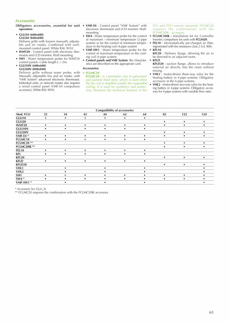
65
Obligatory accessories, essential for unit operation:
• GLLI10 (600x600) GLLI20 (840x840) Delivery grille with louvers manually adjusta-
ble and air intake. Combined with wall-mounted control panel. White RAL 9010.
• WMT20 : Control panel with electronic ther-mostat and LCD monitor. Wall mounting.
• SWI : Water temperature probe for WMT20 control panels. Cable length L = 2m.
• GLLI10N (600x600) GLLI20N (840x840) Delivery grille without water probe, with
Manually adjustable fins and air intake, with "VMF System" advanced electronic thermostat. Individual units, or network master also requires a wired control panel (VMF-E4 compulsory accessory). White RAL 9010.
• VMF-E4 : Control panel “VMF System” with electronic thermostat and LCD monitor. Wall-mounting
• SW4 : Water temperature probe for the control of maximum / minimum temperature (2-pipe system) or for the control of minimum temper-ature in the heating coil (4-pipe system)
• VMF-SW1 : Water temperature probe for the control of maximum temperature in the cool-ing coil (4-pipe system)
• Control panels and VMF System: the character-istics are described on the appropriate card.
Accessories:• FCLMC10 FCLMC20 : is a perimeter case in galvanised
and painted sheet steel, which is used when the fan coil is installed outside the suspended ceiling. It is used for aesthetics and protec-tion, therefore the technical features of the
FCL and FCLI remain unvaried. FCLMC20 requi res the combinat ion wi th the FCLMC20IK accessory.
• FCLMC20IK : Installation kit for Controller Inverter, compulsory for units with FCLM20.
• FEL10 : electrostatically pre-charged air filter, regenerated with fire resistance class 2 (UL 900).
• KFL10 KFL20 : Delivery flange, allowing the air to
be directed to an adjacent room.• KFLD KFLD20 : suction flange, allows to introduce
external air directly into the room without mixing.
• VHL1 : motor-driven three-way valve for the heating battery in 4-pipe systems. Obligatory accessory in the 4-pipe systems.
• VHL2 : motor-driven two-way valve for the heat-ing battery in 4-pipe systems. Obligatory acces-sory for 4-pipe systems with variable flow rates.
Accessories
Compatibility of accessoriesMod. FCLI 32 34 42 44 62 64 82 122 124GLLI10 • • • • • •GLLI20 • • •WMT20 • • • • • • • • •GLLI10N • • • • • •GLLI20N • • •VMF-E4 * • • • • • • • • •FCLMC10 • • • • • •FCLMC20 ** • • •FCLMC20IK ** • • •FEL10 • • • • • •KFL • • • • • •KFL20 • • •KFLD • • • • • •KFLD20 • • •VHL1 • • • •VHL2 • • • •SWI • • • • • • • • •SW4 * • • • • • • • • •VMF-SW1 * • • • •
* Accessory for GLLI_N ** FCLMC20 requires the combination with the FCLMC20IK accessory
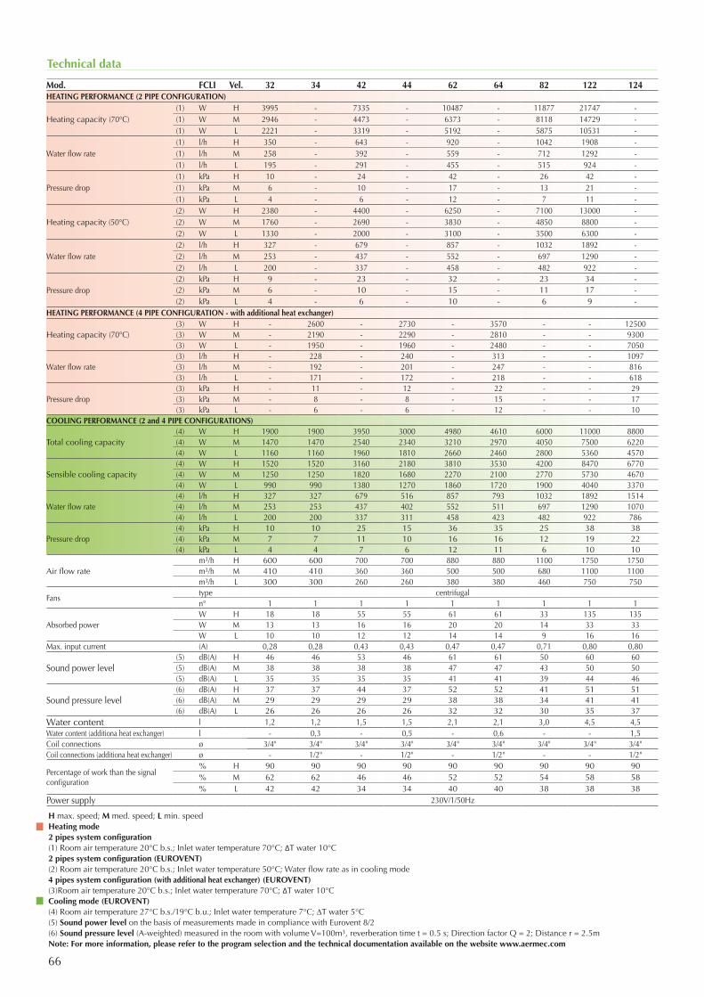
66
Technical data
Mod. FCLI Vel. 32 34 42 44 62 64 82 122 124HEATING PERFORMANCE (2 PIPE CONFIGURATION)
Heating capacity (70°C)(1) W H 3995 - 7335 - 10487 - 11877 21747 -(1) W M 2946 - 4473 - 6373 - 8118 14729 -(1) W L 2221 - 3319 - 5192 - 5875 10531 -
Water flow rate(1) l/h H 350 - 643 - 920 - 1042 1908 -(1) l/h M 258 - 392 - 559 - 712 1292 -(1) l/h L 195 - 291 - 455 - 515 924 -
Pressure drop(1) kPa H 10 - 24 - 42 - 26 42 -(1) kPa M 6 - 10 - 17 - 13 21 -(1) kPa L 4 - 6 - 12 - 7 11 -
Heating capacity (50°C)(2) W H 2380 - 4400 - 6250 - 7100 13000 -(2) W M 1760 - 2690 - 3830 - 4850 8800 -(2) W L 1330 - 2000 - 3100 - 3500 6300 -
Water flow rate(2) l/h H 327 - 679 - 857 - 1032 1892 -(2) l/h M 253 - 437 - 552 - 697 1290 -(2) l/h L 200 - 337 - 458 - 482 922 -
Pressure drop(2) kPa H 9 - 23 - 32 - 23 34 -(2) kPa M 6 - 10 - 15 - 11 17 -(2) kPa L 4 - 6 - 10 - 6 9 -
HEATING PERFORMANCE (4 PIPE CONFIGURATION - with additional heat exchanger)
Heating capacity (70°C)(3) W H - 2600 - 2730 - 3570 - - 12500 (3) W M - 2190 - 2290 - 2810 - - 9300 (3) W L - 1950 - 1960 - 2480 - - 7050
Water flow rate(3) l/h H - 228 - 240 - 313 - - 1097 (3) l/h M - 192 - 201 - 247 - - 816 (3) l/h L - 171 - 172 - 218 - - 618
Pressure drop(3) kPa H - 11 - 12 - 22 - - 29 (3) kPa M - 8 - 8 - 15 - - 17 (3) kPa L - 6 - 6 - 12 - - 10
COOLING PERFORMANCE (2 and 4 PIPE CONFIGURATIONS)
Total cooling capacity(4) W H 1900 1900 3950 3000 4980 4610 6000 11000 8800 (4) W M 1470 1470 2540 2340 3210 2970 4050 7500 6220 (4) W L 1160 1160 1960 1810 2660 2460 2800 5360 4570
Sensible cooling capacity(4) W H 1520 1520 3160 2180 3810 3530 4200 8470 6770 (4) W M 1250 1250 1820 1680 2270 2100 2770 5730 4670 (4) W L 990 990 1380 1270 1860 1720 1900 4040 3370
Water flow rate (4) l/h H 327 327 679 516 857 793 1032 1892 1514 (4) l/h M 253 253 437 402 552 511 697 1290 1070 (4) l/h L 200 200 337 311 458 423 482 922 786
Pressure drop(4) kPa H 10 10 25 15 36 35 25 38 38 (4) kPa M 7 7 11 10 16 16 12 19 22 (4) kPa L 4 4 7 6 12 11 6 10 10
Air flow ratem3/h H 600 600 700 700 880 880 1100 1750 1750 m3/h M 410 410 360 360 500 500 680 1100 1100 m3/h L 300 300 260 260 380 380 460 750 750
Fanstype centrifugaln° 1 1 1 1 1 1 1 1 1
Absorbed powerW H 18 18 55 55 61 61 33 135 135W M 13 13 16 16 20 20 14 33 33W L 10 10 12 12 14 14 9 16 16
Max. input current (A) 0,28 0,28 0,43 0,43 0,47 0,47 0,71 0,80 0,80
Sound power level(5) dB(A) H 46 46 53 46 61 61 50 60 60(5) dB(A) M 38 38 38 38 47 47 43 50 50(5) dB(A) L 35 35 35 35 41 41 39 44 46
Sound pressure level(6) dB(A) H 37 37 44 37 52 52 41 51 51(6) dB(A) M 29 29 29 29 38 38 34 41 41(6) dB(A) L 26 26 26 26 32 32 30 35 37
Water content l 1,2 1,2 1,5 1,5 2,1 2,1 3,0 4,5 4,5Water content (additiona heat exchanger) l - 0,3 - 0,5 - 0,6 - - 1,5Coil connections ø 3/4" 3/4" 3/4" 3/4" 3/4" 3/4" 3/4" 3/4" 3/4"Coil connections (additiona heat exchanger) ø - 1/2" - 1/2" - 1/2" - - 1/2"
Percentage of work than the signal configuration
% H 90 90 90 90 90 90 90 90 90% M 62 62 46 46 52 52 54 58 58% L 42 42 34 34 40 40 38 38 38
Power supply 230V/1/50Hz
H max. speed; M med. speed; L min. speedHeating mode2 pipes system configuration(1) Room air temperature 20°C b.s.; Inlet water temperature 70°C; ΔT water 10°C2 pipes system configuration (EUROVENT)(2) Room air temperature 20°C b.s.; Inlet water temperature 50°C; Water flow rate as in cooling mode4 pipes system configuration (with additional heat exchanger) (EUROVENT)(3)Room air temperature 20°C b.s.; Inlet water temperature 70°C; ΔT water 10°CCooling mode (EUROVENT)(4) Room air temperature 27°C b.s./19°C b.u.; Inlet water temperature 7°C; DT water 5°C(5) Sound power level on the basis of measurements made in compliance with Eurovent 8/2(6) Sound pressure level (A-weighted) measured in the room with volume V=100m3, reverberation time t = 0.5 s; Direction factor Q = 2; Distance r = 2.5mNote: For more information, please refer to the program selection and the technical documentation available on the website www.aermec.com
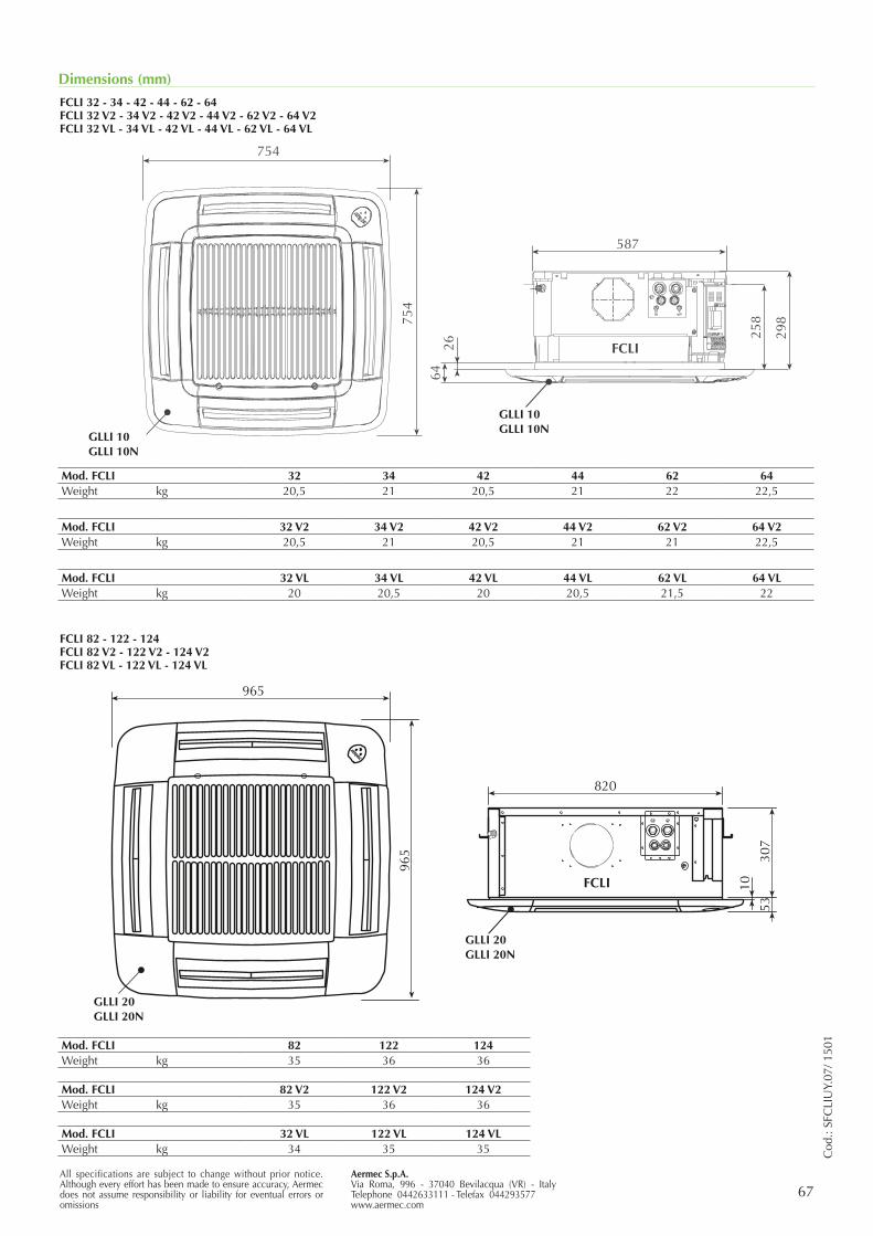
Aermec S.p.A.Via Roma, 996 - 37040 Bevilacqua (VR) - ItalyTelephone 0442633111 - Telefax 044293577www.aermec.com
67All specifications are subject to change without prior notice. Although every effort has been made to ensure accuracy, Aermec does not assume responsibility or liability for eventual errors or omissions
Dimensions (mm)
FCLI 32 - 34 - 42 - 44 - 62 - 64 FCLI 32 V2 - 34 V2 - 42 V2 - 44 V2 - 62 V2 - 64 V2 FCLI 32 VL - 34 VL - 42 VL - 44 VL - 62 VL - 64 VL
Mod. FCLI 32 34 42 44 62 64Weight kg 20,5 21 20,5 21 22 22,5
Mod. FCLI 82 122 124Weight kg 35 36 36
Mod. FCLI 82 V2 122 V2 124 V2Weight kg 35 36 36
Mod. FCLI 32 VL 122 VL 124 VLWeight kg 34 35 35
Mod. FCLI 32 V2 34 V2 42 V2 44 V2 62 V2 64 V2Weight kg 20,5 21 20,5 21 21 22,5
Mod. FCLI 32 VL 34 VL 42 VL 44 VL 62 VL 64 VLWeight kg 20 20,5 20 20,5 21,5 22
Cod
.: SF
CLI
UY.
07/ 1
501
FCLI 82 - 122 - 124 FCLI 82 V2 - 122 V2 - 124 V2 FCLI 82 VL - 122 VL - 124 VL
GLLI20
FCLI
GLLI20
GLLI 10GLLI 10N
GLLI 10GLLI 10N
GLLI 20GLLI 20N
GLLI 20GLLI 20N
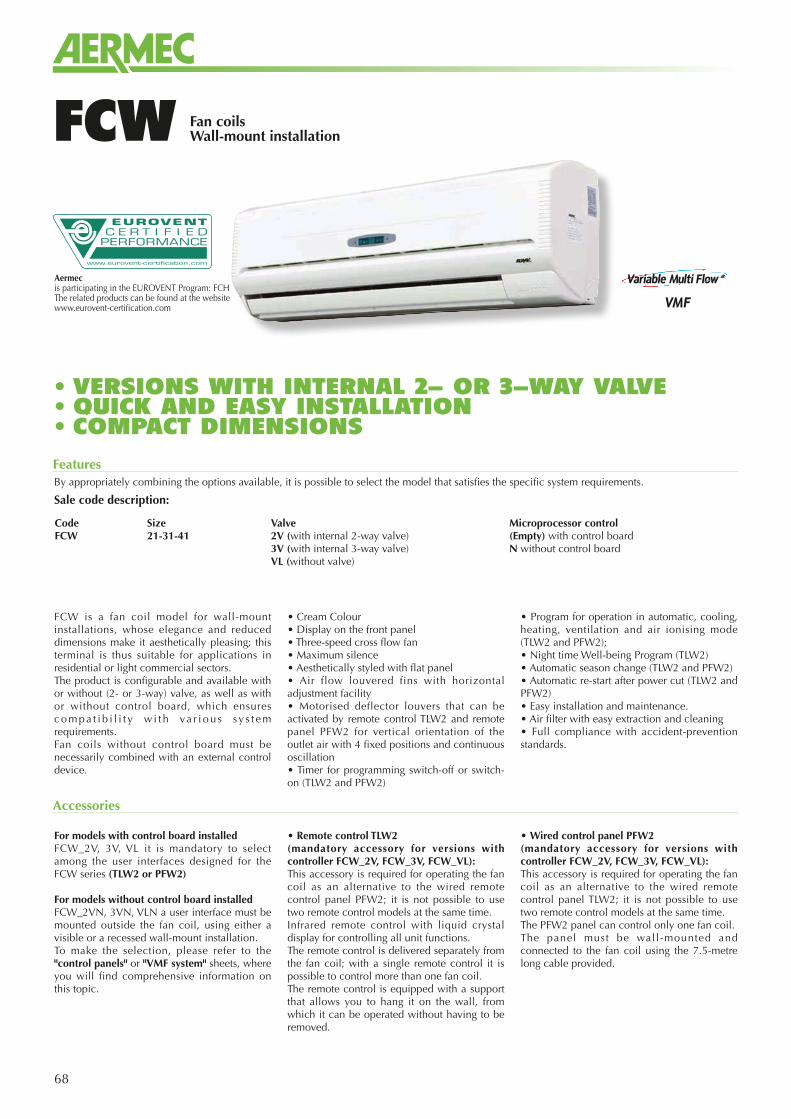
68
Fan coilsWall-mount installationFCW
Features
Accessories
For models with control board installedFCW_2V, 3V, VL it is mandatory to select among the user interfaces designed for the FCW series (TLW2 or PFW2)
For models without control board installedFCW_2VN, 3VN, VLN a user interface must be mounted outside the fan coil, using either a visible or a recessed wall-mount installation. To make the selection, please refer to the "control panels" or "VMF system" sheets, where you will find comprehensive information on this topic.
• Remote control TLW2 (mandatory accessory for versions with controller FCW_2V, FCW_3V, FCW_VL): This accessory is required for operating the fan coil as an alternative to the wired remote control panel PFW2; it is not possible to use two remote control models at the same time.Infrared remote control with liquid crystal display for controlling all unit functions. The remote control is delivered separately from the fan coil; with a single remote control it is possible to control more than one fan coil.The remote control is equipped with a support that allows you to hang it on the wall, from which it can be operated without having to be removed.
• Wired control panel PFW2 (mandatory accessory for versions with controller FCW_2V, FCW_3V, FCW_VL):This accessory is required for operating the fan coil as an alternative to the wired remote control panel TLW2; it is not possible to use two remote control models at the same time.The PFW2 panel can control only one fan coil.The panel must be wall-mounted and connected to the fan coil using the 7.5-metre long cable provided.
Aermecis participating in the EUROVENT Program: FCHThe related products can be found at the website www.eurovent-certification.com
By appropriately combining the options available, it is possible to select the model that satisfies the specific system requirements.
Sale code description:
CodeFCW
Size21-31-41
Valve2V (with internal 2-way valve)3V (with internal 3-way valve)VL (without valve)
Microprocessor control(Empty) with control boardN without control board
FCW is a fan coil model for wall-mount installations, whose elegance and reduced dimensions make it aesthetically pleasing; this terminal is thus suitable for applications in residential or light commercial sectors.The product is configurable and available with or without (2- or 3-way) valve, as well as with or without control board, which ensures c o m p a t i b i l i t y w i t h va r i o u s s y s t e m requirements. Fan coils without control board must be necessarily combined with an external control device.
• Cream Colour• Display on the front panel• Three-speed cross flow fan• Maximum silence• Aesthetically styled with flat panel• Air flow louvered fins with horizontal adjustment facility• Motorised deflector louvers that can be activated by remote control TLW2 and remote panel PFW2 for vertical orientation of the outlet air with 4 fixed positions and continuous oscillation• Timer for programming switch-off or switch-on (TLW2 and PFW2)
• Program for operation in automatic, cooling, heating, ventilation and air ionising mode (TLW2 and PFW2);• Night time Well-being Program (TLW2)• Automatic season change (TLW2 and PFW2)• Automatic re-start after power cut (TLW2 and PFW2)• Easy installation and maintenance.• Air filter with easy extraction and cleaning• Full compliance with accident-prevention standards.
• VERSIONS WITH INTERNAL 2- OR 3-WAY VALVE• QUICK AND EASY INSTALLATION• COMPACT DIMENSIONS
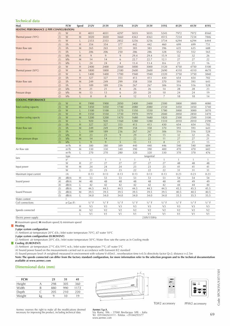
69Aermec S.p.A.Via Roma, 996 - 37040 Bevilacqua (VR) - ItaliaTel. 039 0442633111 - Telefax +39 044293577www.aermec.com
Aermec reserves the right to make all the modifications deemed necessary for improving the product, including technical data.
Mod. FCW Speed 212V 213V 21VL 312V 313V 31VL 412V 413V 41VLHEATING PERFORMANCE (2 PIPE CONFIGURATION)
Thermal power (70°C)(1) W H 4031 4031 4297 5035 5035 5245 7972 7972 8560(1) W M 3020 3020 3660 4363 4363 4515 7234 7234 7846(1) W L 2353 2353 2852 3256 3256 3734 6294 6294 6444
Water flow rate (1) l/h H 354 354 377 442 442 460 699 699 751(1) l/h M 265 265 321 383 383 396 635 635 688(1) l/h L 206 206 250 286 286 328 552 552 565
Pressure drops(1) kPa H 9 9 9 29.4 29.4 15.9 32 32 26(1) kPa M 14 14 6 22.7 22.7 12.1 27 27 22(1) kPa L 24 24 4 13.4 13.4 8.6 21 21 16
Thermal power (50°C)(2) W H 2400 2400 2560 3000 3000 3120 4750 4750 5100(2) W M 1800 1800 2180 2600 2600 2690 4310 4310 4670(2) W L 1400 1400 1700 1940 1940 2220 3750 3750 3840
Water flow rate(2) l/h H 327 327 353 413 413 430 654 654 702(2) l/h M 249 249 299 358 358 370 593 593 643(2) l/h L 189 189 236 267 267 306 516 516 528
Pressure drops(2) kPa H 21 21 8 26 26 14 28 28 23(2) kPa M 13 13 6 20 20 10 24 24 19(2) kPa L 8 8 4 12 12 7 18 18 14
COOLING PERFORMANCE
Total cooling capacity(3) W H 1900 1900 2050 2400 2400 2500 3800 3800 4080(3) W M 1450 1450 1740 2080 2080 2150 3450 3450 3740(3) W L 1100 1100 1370 1550 1550 1780 3000 3000 3070
Sensitive cooling capacity(3) W H 1550 1550 1730 1970 1970 2040 2850 2850 3470(3) W M 1200 1200 1470 1680 1680 1820 2500 2500 3100(3) W L 920 920 1160 1280 1280 1510 2010 2010 2590
Water flow rate(3) l/h H 327 327 353 413 413 430 654 654 702(3) l/h M 249 249 299 358 358 370 593 593 643(3) l/h L 189 189 236 267 267 306 516 516 528
Water pressure drops(3) kPa H 23 23 9 29 29 15 32 32 26(3) kPa M 14 14 7 22 22 11 27 27 21(3) kPa L 9 9 5 13 13 8 21 21 15
Air flow ratem3/h H 380 380 389 440 440 446 540 540 684m3/h M 330 330 340 390 390 400 470 470 602m3/h L 270 270 280 320 320 330 370 370 476
fanstype tangentialn° 1 1 1 1 1 1 1 1 1
Input powerW H 27 27 27 27 27 27 48 48 48W M 24 24 24 23 23 23 41 41 41W L 23 23 23 22 22 22 31 31 31
Maximum input current (A) 0.13 0.13 0.13 0.13 0.13 0.13 0.23 0.23 0.23
Sound power(4) dB(A) H 53 53 53 53 53 53 54 54 54(4) dB(A) M 48 48 48 48 48 48 49 49 49(4) dB(A) L 42 42 42 42 42 42 44 44 44
Sound Pressure(5) dB(A) H 44.5 44.5 44.5 44.5 44.5 44.5 45.5 45.5 45.5(5) dB(A) M 39.5 39.5 39.5 39.5 39.5 39.5 40.5 40.5 40.5(5) dB(A) L 34.0 34.0 34.0 34.0 34.0 34.0 35.5 35.5 35.5
Water content lCoil connections ø Gas (F) ½” F ½” F ½” F ½” F ½” F ½” F ½” F ½” F ½” F
Speeds connectedH V3 V3 V3 V3 V3 V3 V3 V3 V3M V2 V2 V2 V2 V2 V2 V2 V2 V2L V1 V1 V1 V1 V1 V1 V1 V1 V1
Electric power supply 230V/1/50HzC
ode:
SFC
W3V
UY.
07/1
501
Technical data
Dimensional data (mm)
B
A
C
TLW2 accessory PFW2 accessory
FCW 21 31 41Height A 298 305 360Width B 880 990 1172Depth C 205 210 220Weight kg 9 10 19
H maximum speed; M medium speed; L minimum speedHeating2-pipe system configuration(1) Ambient air temperature 20°C d.b.; Inlet water temperature 70°C; DT water 10°C2-pipe system configuration (EUROVENT)(2) Ambient air temperature 20°C d.b.; Inlet water temperature 50°C; Water flow rate the same as in Cooling modeCooling (EUROVENT)(3) Ambient air temperature 27°C d.b./19°C w.b.; Inlet water temperature 7°C; DT water 5°C(4) Sound power based on the measurements carried out in accordance with Eurovent 8/2 standard(5) Sound pressure level (A weighted) measured in environment with volume V=85m3 , reverberation time t=0.5s directivity factor Q=2; distance r=2.5mNote: The speeds connected can differ from the factory standard configuration, for more information refer to the selection program and to the technical documentation available at www.aermec.com
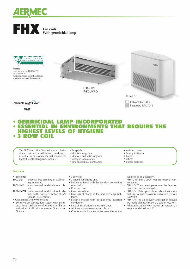
70
• Versions:FHX-UV: universal free-standing or wall/ceil-
ing mounting.FHX-UVP: wall-mounted model without cabi-
net.FHX-UVPO: wall-mounted model without cabi-
net, with boosted motor at 6/7 speeds (3 selectable).
• Compatible with VMF System.• Exclusive air sterilization system with germi-
cidal lamps. Efficiency of 99.999% in the de-activation of all microorganism Gram - and Gram +
• 3 row coil.• 3-speed ventilating unit.• Full compliance with the accident prevention
standards.• Rounded line.• Quiet operation.• Low loss of charge in the heat exchange bat-
teries.• Electric motors with permanently inserted
condensers.• Ease of installation and maintenance.• Air filter easy to remove and clean.• Control made by a microprocessor thermostat
supplied as an accessory:- FHX-UVP and UVPO: requires external con-
trol panel.- FHX-UV: The control panel may be fitted on
board the unit or externally.• FHX-UV: Metal protection cabinet with var-
nishing in anticorrosion polyester, colour RAL9002.
• FHX-UV: The air delivery and suction louvers are made of plastic material, colour RAL7044
• Adjustable air delivery louver on version UV except models 62 and 82.
Features
The FHX fan coil is fitted with an exclusive device for air sterilization, making it essential in environments that require the highest levels of hygiene, such as:
• hospitals• dentists' surgeries • doctors' and vets' surgeries • analysis laboratories • pharmaceutical companies
• waiting rooms• beauty institutes • homes • offices • public premises
Aermecparticipate in the EUROVENTprogram: FCHthe products are present on the site www.eurovent-certification.com
Fan coilsWith germicidal lampFHX
FHX-UV
FHX-UVPFHX-UVPO
Cabinet RAL 9002heatboard RAL 7044
• GERMICIDAL LAMP INCORPORATED• ESSENTIAL IN ENVIRONMENTS THAT REQUIRE THE HIGHEST LEVELS OF HYGIENE
• 3 ROW COIL
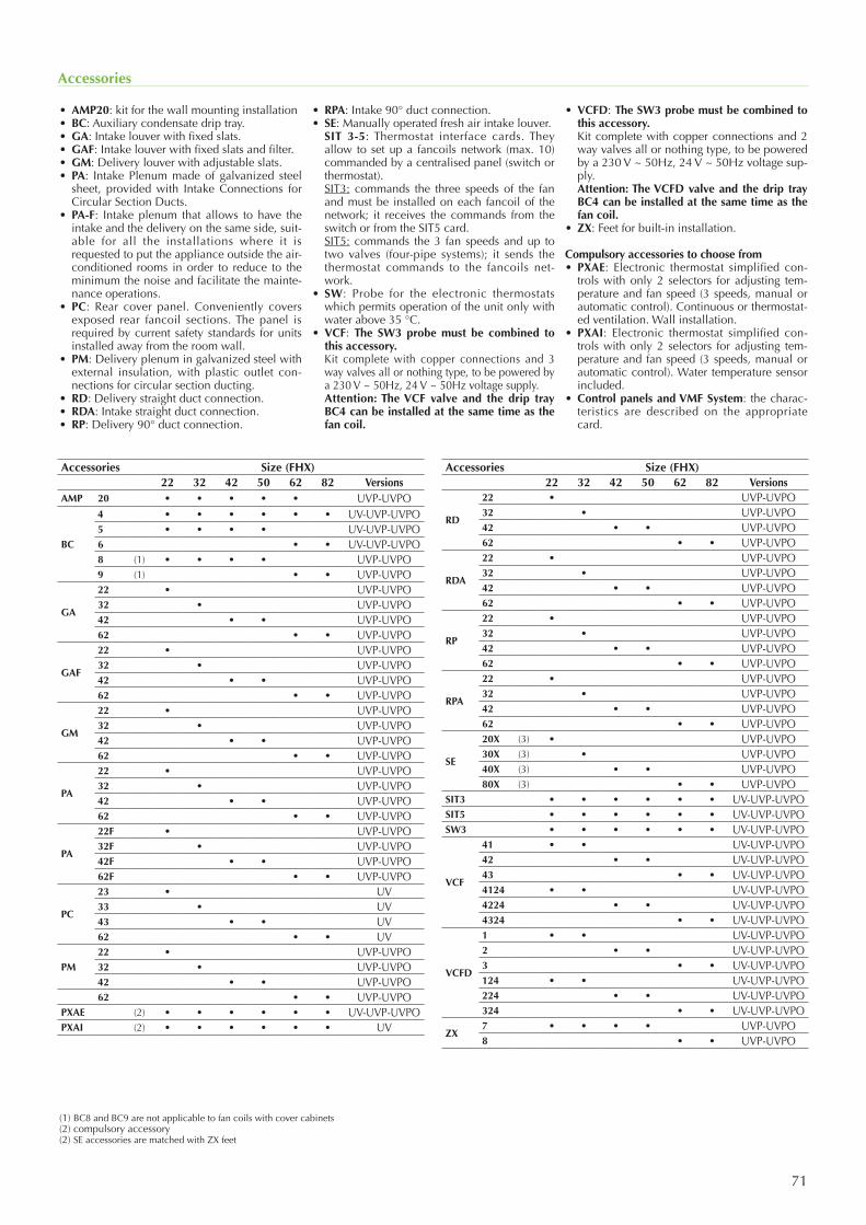
71
Accessories
• AMP20: kit for the wall mounting installation• BC: Auxiliary condensate drip tray.• GA: Intake louver with fixed slats.• GAF: Intake louver with fixed slats and filter.• GM: Delivery louver with adjustable slats.• PA: Intake Plenum made of galvanized steel
sheet, provided with Intake Connections for Circular Section Ducts.
• PA-F: Intake plenum that allows to have the intake and the delivery on the same side, suit-able for all the installations where it is requested to put the appliance outside the air-conditioned rooms in order to reduce to the minimum the noise and facilitate the mainte-nance operations.
• PC: Rear cover panel. Conveniently covers exposed rear fancoil sections. The panel is required by current safety standards for units installed away from the room wall.
• PM: Delivery plenum in galvanized steel with external insulation, with plastic outlet con-nections for circular section ducting.
• RD: Delivery straight duct connection.• RDA: Intake straight duct connection.• RP: Delivery 90° duct connection.
• RPA: Intake 90° duct connection.• SE: Manually operated fresh air intake louver. SIT 3-5: Thermostat interface cards. They
allow to set up a fancoils network (max. 10) commanded by a centralised panel (switch or thermostat).
SIT3: commands the three speeds of the fan and must be installed on each fancoil of the network; it receives the commands from the switch or from the SIT5 card.
SIT5: commands the 3 fan speeds and up to two valves (four-pipe systems); it sends the thermostat commands to the fancoils net-work.
• SW: Probe for the electronic thermostats which permits operation of the unit only with water above 35 °C.
• VCF: The SW3 probe must be combined to this accessory.
Kit complete with copper connections and 3 way valves all or nothing type, to be powered by a 230 V ~ 50Hz, 24 V ~ 50Hz voltage supply.
Attention: The VCF valve and the drip tray BC4 can be installed at the same time as the fan coil.
• VCFD: The SW3 probe must be combined to this accessory.
Kit complete with copper connections and 2 way valves all or nothing type, to be powered by a 230 V ~ 50Hz, 24 V ~ 50Hz voltage sup-ply.
Attention: The VCFD valve and the drip tray BC4 can be installed at the same time as the fan coil.
• ZX: Feet for built-in installation.
Compulsory accessories to choose from• PXAE: Electronic thermostat simplified con-
trols with only 2 selectors for adjusting tem-perature and fan speed (3 speeds, manual or automatic control). Continuous or thermostat-ed ventilation. Wall installation.
• PXAI: Electronic thermostat simplified con-trols with only 2 selectors for adjusting tem-perature and fan speed (3 speeds, manual or automatic control). Water temperature sensor included.
• Control panels and VMF System: the charac-teristics are described on the appropriate card.
Accessories Size (FHX)22 32 42 50 62 82 Versions
AMP 20 • • • • • UVP-UVPO
BC
4 • • • • • • UV-UVP-UVPO5 • • • • UV-UVP-UVPO6 • • UV-UVP-UVPO8 (1) • • • • UVP-UVPO9 (1) • • UVP-UVPO
GA
22 • UVP-UVPO32 • UVP-UVPO42 • • UVP-UVPO62 • • UVP-UVPO
GAF
22 • UVP-UVPO32 • UVP-UVPO42 • • UVP-UVPO62 • • UVP-UVPO
GM
22 • UVP-UVPO32 • UVP-UVPO42 • • UVP-UVPO62 • • UVP-UVPO
PA
22 • UVP-UVPO32 • UVP-UVPO42 • • UVP-UVPO62 • • UVP-UVPO
PA
22F • UVP-UVPO32F • UVP-UVPO42F • • UVP-UVPO62F • • UVP-UVPO
PC
23 • UV33 • UV43 • • UV62 • • UV
PM22 • UVP-UVPO32 • UVP-UVPO42 • • UVP-UVPO62 • • UVP-UVPO
PXAE (2) • • • • • • UV-UVP-UVPOPXAI (2) • • • • • • UV
Accessories Size (FHX)22 32 42 50 62 82 Versions
RD
22 • UVP-UVPO32 • UVP-UVPO42 • • UVP-UVPO62 • • UVP-UVPO
RDA
22 • UVP-UVPO32 • UVP-UVPO42 • • UVP-UVPO62 • • UVP-UVPO
RP
22 • UVP-UVPO32 • UVP-UVPO42 • • UVP-UVPO62 • • UVP-UVPO
RPA
22 • UVP-UVPO32 • UVP-UVPO42 • • UVP-UVPO62 • • UVP-UVPO
SE
20X (3) • UVP-UVPO30X (3) • UVP-UVPO40X (3) • • UVP-UVPO80X (3) • • UVP-UVPO
SIT3 • • • • • • UV-UVP-UVPOSIT5 • • • • • • UV-UVP-UVPOSW3 • • • • • • UV-UVP-UVPO
VCF
41 • • UV-UVP-UVPO42 • • UV-UVP-UVPO43 • • UV-UVP-UVPO4124 • • UV-UVP-UVPO4224 • • UV-UVP-UVPO4324 • • UV-UVP-UVPO
VCFD
1 • • UV-UVP-UVPO2 • • UV-UVP-UVPO3 • • UV-UVP-UVPO124 • • UV-UVP-UVPO224 • • UV-UVP-UVPO324 • • UV-UVP-UVPO
ZX7 • • • • UVP-UVPO8 • • UVP-UVPO
(1) BC8 and BC9 are not applicable to fan coils with cover cabinets(2) compulsory accessory(2) SE accessories are matched with ZX feet
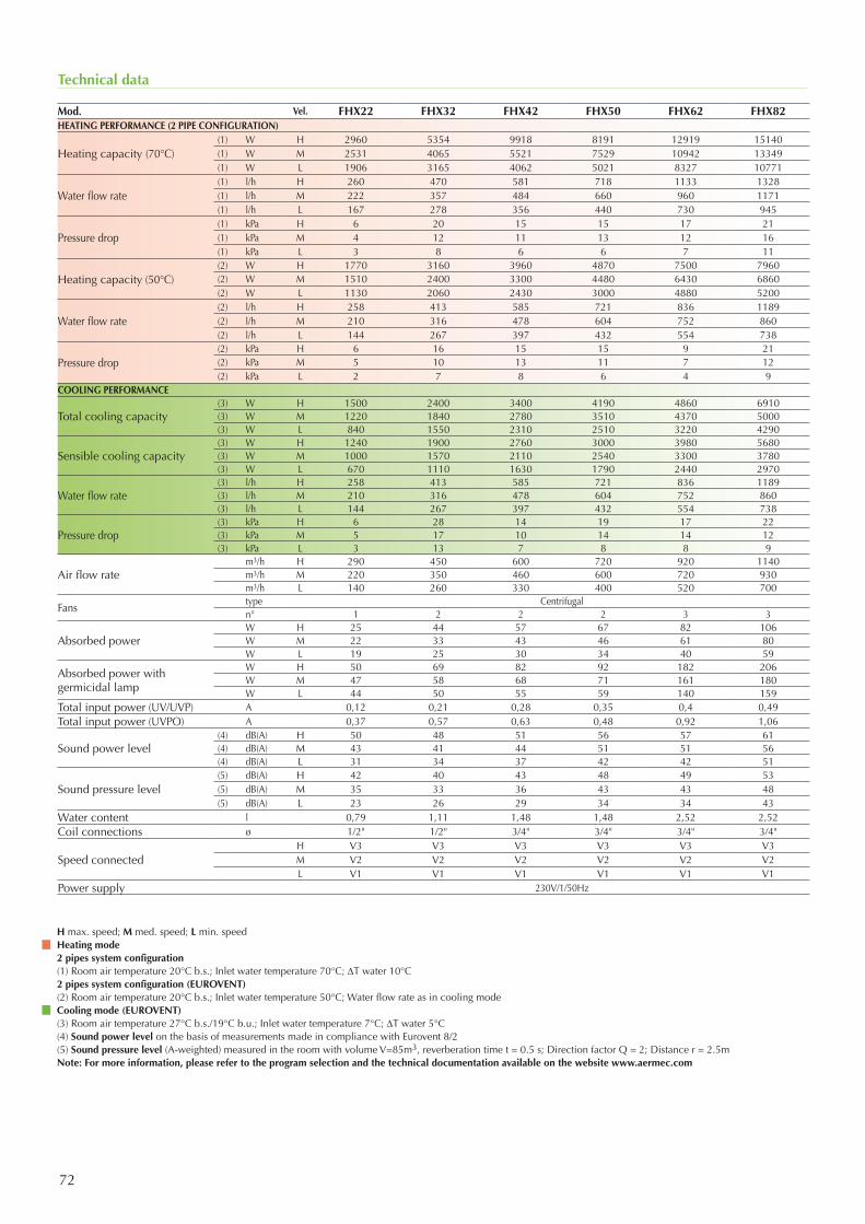
72
Technical data
Mod. Vel. FHX22 FHX32 FHX42 FHX50 FHX62 FHX82HEATING PERFORMANCE (2 PIPE CONFIGURATION)
Heating capacity (70°C)(1) W H 2960 5354 9918 8191 12919 15140(1) W M 2531 4065 5521 7529 10942 13349(1) W L 1906 3165 4062 5021 8327 10771
Water flow rate(1) l/h H 260 470 581 718 1133 1328(1) l/h M 222 357 484 660 960 1171(1) l/h L 167 278 356 440 730 945
Pressure drop(1) kPa H 6 20 15 15 17 21(1) kPa M 4 12 11 13 12 16(1) kPa L 3 8 6 6 7 11
Heating capacity (50°C)(2) W H 1770 3160 3960 4870 7500 7960(2) W M 1510 2400 3300 4480 6430 6860(2) W L 1130 2060 2430 3000 4880 5200
Water flow rate(2) l/h H 258 413 585 721 836 1189(2) l/h M 210 316 478 604 752 860(2) l/h L 144 267 397 432 554 738
Pressure drop(2) kPa H 6 16 15 15 9 21(2) kPa M 5 10 13 11 7 12(2) kPa L 2 7 8 6 4 9
COOLING PERFORMANCE
Total cooling capacity(3) W H 1500 2400 3400 4190 4860 6910(3) W M 1220 1840 2780 3510 4370 5000(3) W L 840 1550 2310 2510 3220 4290
Sensible cooling capacity(3) W H 1240 1900 2760 3000 3980 5680(3) W M 1000 1570 2110 2540 3300 3780(3) W L 670 1110 1630 1790 2440 2970
Water flow rate (3) l/h H 258 413 585 721 836 1189(3) l/h M 210 316 478 604 752 860(3) l/h L 144 267 397 432 554 738
Pressure drop(3) kPa H 6 28 14 19 17 22(3) kPa M 5 17 10 14 14 12(3) kPa L 3 13 7 8 8 9
Air flow ratem3/h H 290 450 600 720 920 1140m3/h M 220 350 460 600 720 930m3/h L 140 260 330 400 520 700
Fanstype Centrifugaln° 1 2 2 2 3 3
Absorbed powerW H 25 44 57 67 82 106W M 22 33 43 46 61 80W L 19 25 30 34 40 59
Absorbed power with germicidal lamp
W H 50 69 82 92 182 206W M 47 58 68 71 161 180W L 44 50 55 59 140 159
Total input power (UV/UVP) A 0,12 0,21 0,28 0,35 0,4 0,49Total input power (UVPO) A 0,37 0,57 0,63 0,48 0,92 1,06
Sound power level(4) dB(A) H 50 48 51 56 57 61(4) dB(A) M 43 41 44 51 51 56(4) dB(A) L 31 34 37 42 42 51
Sound pressure level(5) dB(A) H 42 40 43 48 49 53(5) dB(A) M 35 33 36 43 43 48(5) dB(A) L 23 26 29 34 34 43
Water content l 0,79 1,11 1,48 1,48 2,52 2,52Coil connections ø 1/2" 1/2" 3/4" 3/4" 3/4" 3/4"
Speed connectedH V3 V3 V3 V3 V3 V3M V2 V2 V2 V2 V2 V2L V1 V1 V1 V1 V1 V1
Power supply 230V/1/50Hz
H max. speed; M med. speed; L min. speedHeating mode2 pipes system configuration(1) Room air temperature 20°C b.s.; Inlet water temperature 70°C; DT water 10°C2 pipes system configuration (EUROVENT)(2) Room air temperature 20°C b.s.; Inlet water temperature 50°C; Water flow rate as in cooling modeCooling mode (EUROVENT)(3) Room air temperature 27°C b.s./19°C b.u.; Inlet water temperature 7°C; DT water 5°C(4) Sound power level on the basis of measurements made in compliance with Eurovent 8/2(5) Sound pressure level (A-weighted) measured in the room with volume V=85m3, reverberation time t = 0.5 s; Direction factor Q = 2; Distance r = 2.5mNote: For more information, please refer to the program selection and the technical documentation available on the website www.aermec.com
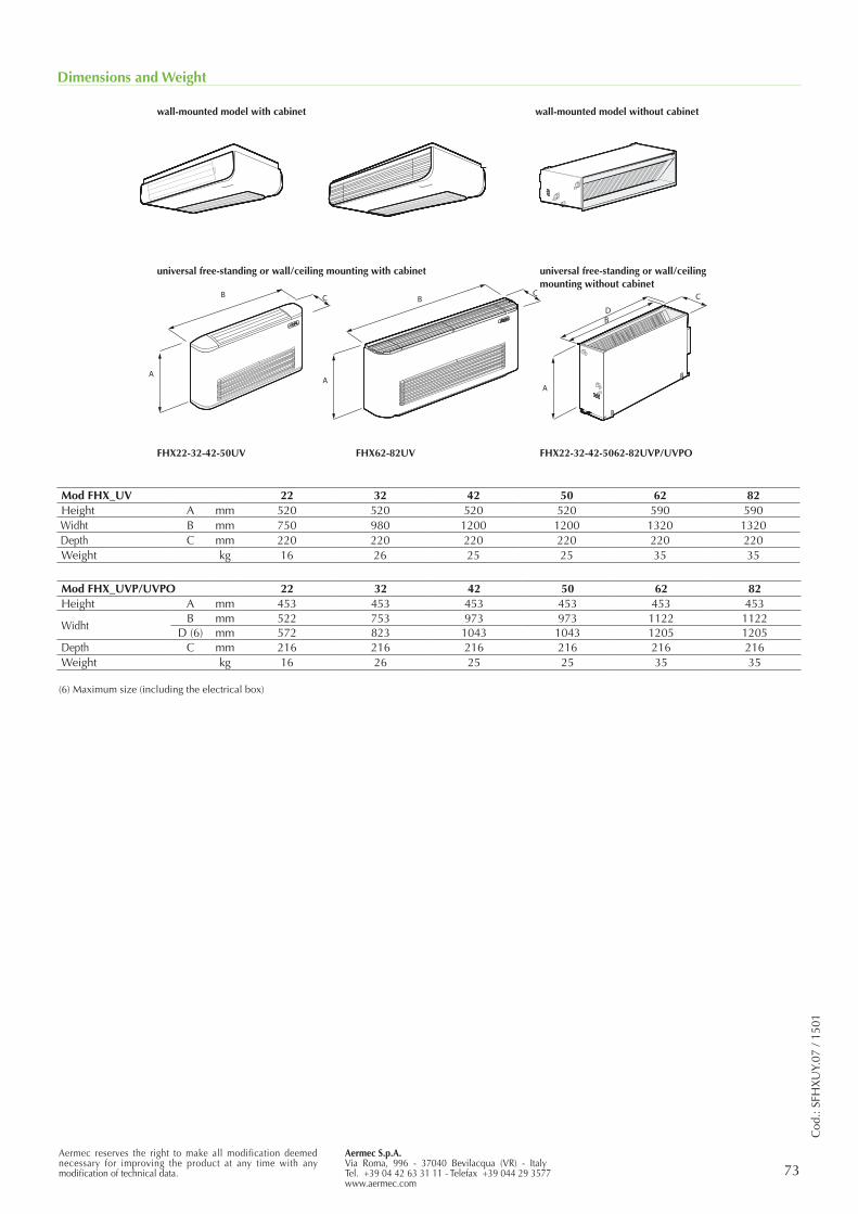
Aermec S.p.A.Via Roma, 996 - 37040 Bevilacqua (VR) - ItalyTel. +39 04 42 63 31 11 - Telefax +39 044 29 3577www.aermec.com
73Aermec reserves the right to make all modification deemed necessary for improving the product at any time with any modification of technical data.
Cod
.: SF
HX
UY.
07 /
1501
Dimensions and Weight
AA
A
B B
BD
C C C
FHX22-32-42-50UV
universal free-standing or wall/ceiling mounting with cabinet universal free-standing or wall/ceiling mounting without cabinet
wall-mounted model with cabinet wall-mounted model without cabinet
FHX62-82UV FHX22-32-42-5062-82UVP/UVPO
(6) Maximum size (including the electrical box)
Mod FHX_UV 22 32 42 50 62 82Height A mm 520 520 520 520 590 590Widht B mm 750 980 1200 1200 1320 1320Depth C mm 220 220 220 220 220 220Weight kg 16 26 25 25 35 35
Mod FHX_UVP/UVPO 22 32 42 50 62 82Height A mm 453 453 453 453 453 453
WidhtB mm 522 753 973 973 1122 1122
D (6) mm 572 823 1043 1043 1205 1205Depth C mm 216 216 216 216 216 216Weight kg 16 26 25 25 35 35
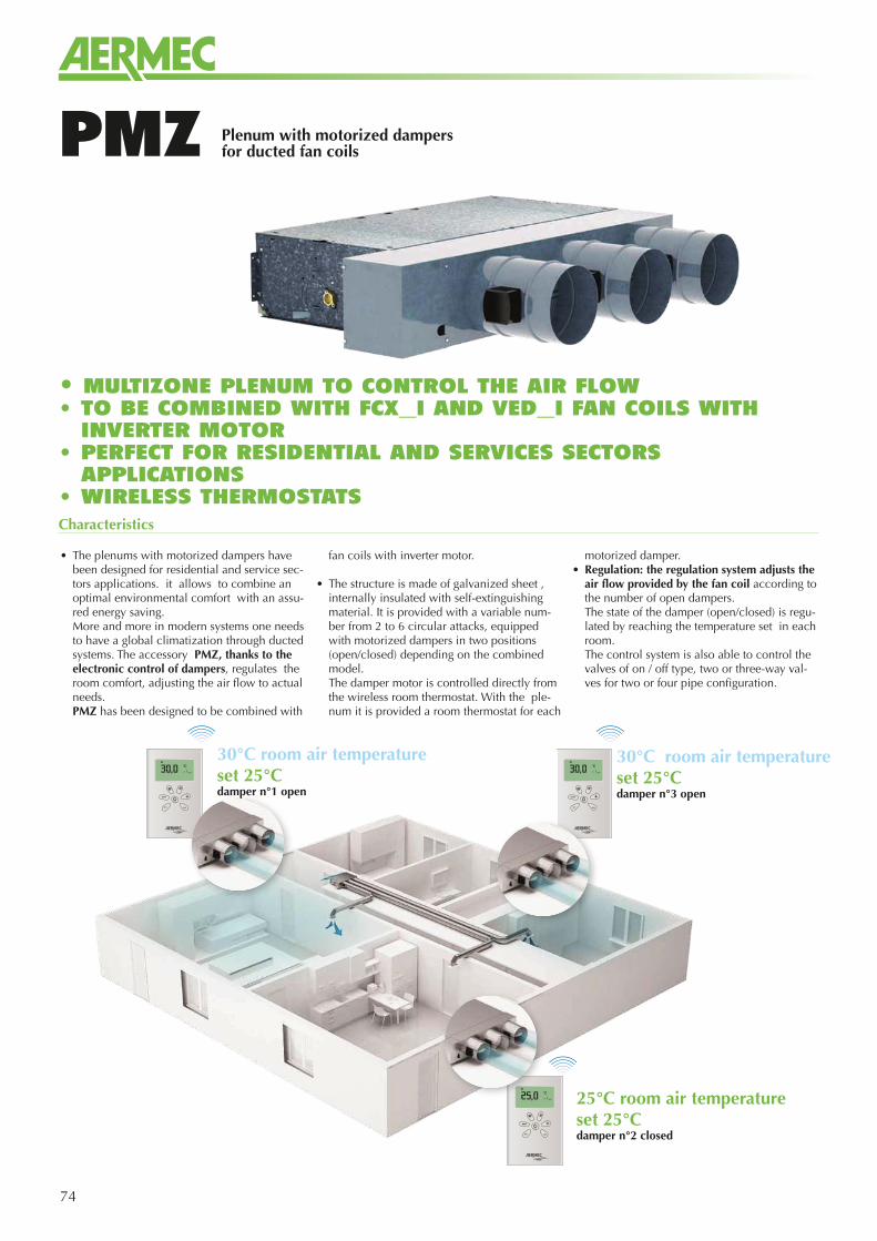
74
PMZ
Characteristics
• The plenums with motorized dampers have been designed for residential and service sec-tors applications. it allows to combine an optimal environmental comfort with an assu-red energy saving. More and more in modern systems one needs to have a global climatization through ducted systems. The accessory PMZ, thanks to the electronic control of dampers, regulates the room comfort, adjusting the air flow to actual needs.
PMZ has been designed to be combined with
fan coils with inverter motor.
• The structure is made of galvanized sheet , internally insulated with self-extinguishing material. It is provided with a variable num-ber from 2 to 6 circular attacks, equipped with motorized dampers in two positions (open/closed) depending on the combined model.
The damper motor is controlled directly from the wireless room thermostat. With the ple-num it is provided a room thermostat for each
motorized damper.• Regulation: the regulation system adjusts the
air flow provided by the fan coil according to the number of open dampers.
The state of the damper (open/closed) is regu-lated by reaching the temperature set in each room.
The control system is also able to control the valves of on / off type, two or three-way val-ves for two or four pipe configuration.
(1) Alle condizioni di portate aria e acqua nominali
Plenum with motorized dampers for ducted fan coils
30°C room air temperatureset 25°Cdamper n°1 open
30°C room air temperatureset 25°Cdamper n°3 open
25°C room air temperatureset 25°Cdamper n°2 closed
• MULTIZONE PLENUM TO CONTROL THE AIR FLOW • TO BE COMBINED WITH FCX_I AND VED_I FAN COILS WITH
INVERTER MOTOR • PERFECT FOR RESIDENTIAL AND SERVICES SECTORS
APPLICATIONS• WIRELESS THERMOSTATS
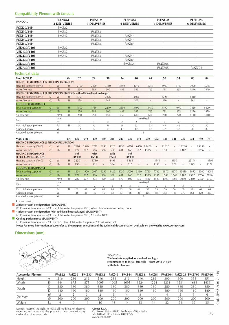
75Aermec S.p.A.Via Roma, 996 - 37040 Bevilacqua (VR) - ItaliaTel. 0442633111 - Telefax 044293577www.aermec.com
Aermec reserves the right to make all modification deemed necessary for improving the product at any time with any modification of technical data.
Compatibility Plenum with fancoils
Dimensions (mm)
FANCOILPLENUM
2 DELIVERIESPLENUM
3 DELIVERIESPLENUM
4 DELIVERIESPLENUM
5 DELIVERIESPLENUM
6 DELIVERIESFCXI20/24P PMZ22 - - - -FCXI30/34P PMZ32 PMZ33 - - -FCXI40/44P PMZ42 PMZ43 PMZ44 - -FCXI50/54P - PMZ43 PMZ44 - -FCXI80/84P - PMZ83 PMZ84 - -VED030/040I PMZ22 - - - -VED130/140I PMZ32 PMZ33 - - -VED230/240I PMZ42 PMZ43 PMZ44 - -VED330/340I - PMZ83 PMZ84 - -VED530/540I - - PMZ504 PMZ505 -VED730/740I - - - PMZ705 PMZ706
AB
D
C
200
200
200
Acessories Plenum PMZ22 PMZ32 PMZ33 PMZ42 PMZ43 PMZ44 PMZ83 PMZ84 PMZ504 PMZ505 PMZ705 PMZ706Height A 216 216 216 216 216 216 216 216 300 300 351 351Width B 644 875 875 1095 1095 1095 1224 1224 1231 1231 1631 1631
DepthC 380 380 380 380 380 380 380 380 380 380 380 380D 180 180 180 180 180 180 180 180 180 180 180 180
Deliveryn° 2 2 3 2 3 4 3 4 4 5 5 6Ø 200 200 200 200 200 200 200 200 200 200 200 200
Weight kg 9 9 11 10 13 14 13 14 22 24 32 35 Cod
.: SP
MZ
UY.
01 /
1410
Mod. FCXI_P Vel. 20 24 30 34 40 44 50 54 80 84HEATING PERFORMANCE (2 PIPE CONFIGURATION)Heating capacity (50°C) (1) W H 2100 2320 3160 3550 4240 5250 4900 6100 7990 10207Water flow rate (1) l/h H 258 298 380 482 585 765 721 855 1276 1479HEATING PERFORMANCE (4 PIPE CONFIGURATION - with additional heat exchanger)Heating capacity (70°C) (2) W H 1751 - 2826 - 3460 - 4223 - 6410 -Water flow rate (2) l/h H 154 - 248 - 303 - 370 - 562 -COOLING PERFORMANCETotal cooling capacity (3) W H 1500 1730 2210 2800 3400 4450 4190 4970 7420 8600Water flow rate (3) l/h H 258 298 380 482 585 765 721 855 1276 1479Air flow rate m3/h H 290 290 450 450 600 600 720 720 1140 1140
Fanstype centrifugaln° 1 1 2 2 2 2 2 2 3 3
Max. high static pressure Pa H 50 50 56 56 53 53 46 46 30 30Absorbed power W 12 12 13 13 17 17 37 37 80 80Absorbed power (plenum) W 5
Mod. VED_I Vel. 030 040 130 140 230 240 330 340 530 532 540 541 730 732 740 741HEATING PERFORMANCE (2 PIPE CONFIGURATION)Heating capacity (50°C) (1) W H 2180 2340 3750 3940 4320 4750 6270 6550 10420 - 11820 - 17280 - 19150 -Water flow rate (1) l/h H 279 327 516 566 588 691 860 922 1335 - 1543 - 2382 - 2766 -HEATING PERFORMANCE (4 PIPE CONFIGURATION)
with BV030
with BV130
with BV230
with BV330
Heating capacity (70°C) (2) W H 2220 - 3780 - 4493 - 5888 - - 13540 - 8850 - 22174 - 14500Water flow rate (2) l/h H 196 - 331 - 394 - 515 - - 1188 - 776 - 1945 - 1272COOLING PERFORMANCETotal cooling capacity (3) W H 1624 1900 2997 3290 3420 4020 5000 5360 7760 7760 8970 8970 13850 13850 16080 16080Water flow rate (3) l/h H 279 327 516 566 588 691 860 922 1335 1335 1543 1543 2382 2382 2766 2766Air flow rate m3/h H 285 277 433 420 590 570 805 775 1520 1520 1500 1500 2410 2410 2350 2350
Fanstype centrifugaln° 1 1 2 2 2 2 3 3 2 2 2 2 3 3 3 3
Max. high static pressure Pa H 61 61 60 60 64 63 66 64 58 56 56 56 69 69 69 69Absorbed power W 36 36 45 45 53 53 86 86 205 185 205 185 370 363 370 363Absorbed power (plenum) W 5
H max. speed; 2 pipes system configuration (EUROVENT)(1) Room air temperature 20°C b.s.; Inlet water temperare 50°C; Water flow rate as in cooling mode4 pipes system configuration (with additional heat exchanger) (EUROVENT)(2) Room air temperature 20°C b.s.; Inlet water temperare 70°C; ΔT water 10°CCooling performance (EUROVENT)(3) Room air temperature 27°C b.s./19°C b.u.; Inlet water temperare 7°C; DT water 5°CNote: For more information, please refer to the program selection and the technical documentation available on the website www.aermec.com
Technical data
WARNING The brackets supplied as standard are higly recommended to install fan coils – from 20 to 54 size – with their plenums
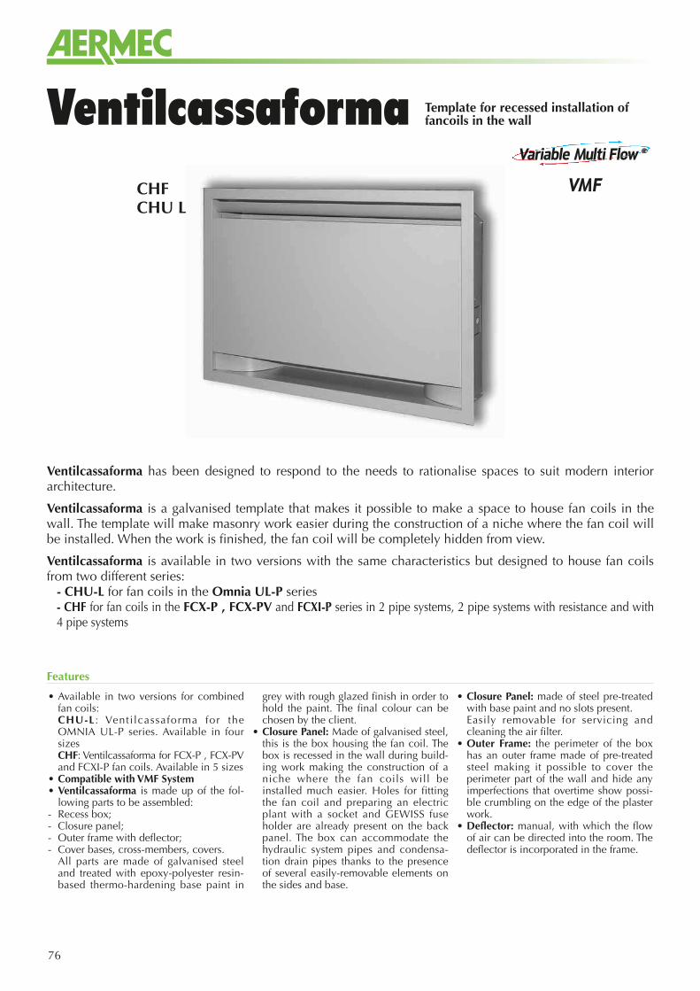
76
Ventilcassaforma has been designed to respond to the needs to rationalise spaces to suit modern interior architecture.
Ventilcassaforma is a galvanised template that makes it possible to make a space to house fan coils in the wall. The template will make masonry work easier during the construction of a niche where the fan coil will be installed. When the work is finished, the fan coil will be completely hidden from view.
Ventilcassaforma is available in two versions with the same characteristics but designed to house fan coils from two different series:
- CHU-L for fan coils in the Omnia UL-P series- CHF for fan coils in the FCX-P , FCX-PV and FCXI-P series in 2 pipe systems, 2 pipe systems with resistance and with 4 pipe systems
CHFCHU L
Template for recessed installation of fancoils in the wallVentilcassaforma
• Available in two versions for combined fan coils:
CHU-L : Venti lcassaforma for the OMNIA UL-P series. Available in four sizes
CHF: Ventilcassaforma for FCX-P , FCX-PV and FCXI-P fan coils. Available in 5 sizes
• Compatible with VMF System• Ventilcassaforma is made up of the fol-
lowing parts to be assembled:- Recess box;- Closure panel;- Outer frame with deflector;- Cover bases, cross-members, covers. All parts are made of galvanised steel
and treated with epoxy-polyester resin-based thermo-hardening base paint in
grey with rough glazed finish in order to hold the paint. The final colour can be chosen by the client.
• Closure Panel: Made of galvanised steel, this is the box housing the fan coil. The box is recessed in the wall during build-ing work making the construction of a niche where the fan coils will be installed much easier. Holes for fitting the fan coil and preparing an electric plant with a socket and GEWISS fuse holder are already present on the back panel. The box can accommodate the hydraulic system pipes and condensa-tion drain pipes thanks to the presence of several easily-removable elements on the sides and base.
• Closure Panel: made of steel pre-treated with base paint and no slots present.
Easily removable for servicing and cleaning the air filter.
• Outer Frame: the perimeter of the box has an outer frame made of pre-treated steel making it possible to cover the perimeter part of the wall and hide any imperfections that overtime show possi-ble crumbling on the edge of the plaster work.
• Deflector: manual, with which the flow of air can be directed into the room. The deflector is incorporated in the frame.
Features
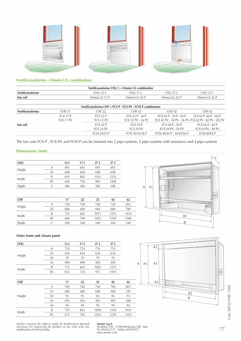
Aermec S.p.A.Via Roma, 996 - 37040 Bevilacqua (VR) - ItalyTel. 0442633111 - Telefax 044293577www.aermec.com
77Aermec reserves the right to make all modification deemed necessary for improving the product at any time with any modification of technical data.
Dimensions (mm)
Ventilcassaforma - Omnia UL combination
A4
Outer frame and closure panel
Cod
.: SV
C2U
Y.08
/ 15
02
The fan coils FCX-P , FCX-PV and FCXI-P can be inserted into 2 pipe systems, 2 pipe systems with resistance and 4 pipe systems
CHU 12 L 17 L 27 L 37 L
HeightA 691 691 691 691
A1 648 648 648 648
WidthB 692 802 1032 1252
B1 644 754 984 1204Depth C 186 186 186 186
CHU 12 L 17 L 27 L 37 L
Height
A 724 724 724 724A1 634 634 634 634A2 70 70 70 70A3 494 494 494 494
WidthB 713 823 1053 1273
B1 633 743 973 1193
CHF 17 22 32 42 62
HeightA 728 728 728 728 833
A1 684 684 684 684 789
WidthB 732 842 1073 1293 1414
B1 684 794 1025 1245 1366Depth C 240 240 240 240 240
CHF 17 22 32 42 62
Height
A 760 760 760 760 865A1 680 680 680 680 785A2 93 93 93 93 93A3 493 493 493 493 598A4 94 94 94 94 94
WidthB 753 863 1094 1314 1435
B1 673 783 1014 1234 1355
Ventilcassaforma CHU L + Omnia UL combinationVentilcassaforma CHU 12 L CHU 17 L CHU 27 L CHU 37 LFan coil Omnia UL 11 P Omnia UL 16 P Omnia UL 26 P Omnia UL 36 P
Ventilcassaforma CHF + FCX P - FCX PV - FCXI P combinationVentilcassaforma CHF 17 CHF 22 CHF 32 CHF 42 CHF 62
Fan coil
FCX 17 PFCX 17 PV
FCX 22 P FCX 22 PV
FCX 32 P - 36 PFCX 32 PV - 36 PV
FCX 42 P - 50 P - 56 PFCX 42 PV - 50 PV - 56 PV
FCX 62 P - 82 P - 102 PFCX 62 PV - 82 PV - 102 PV
FCX 24 PFCX 24 PV
FCX 34 PFCX 34 PV
FCX 44 P - 54 PFCX 44 PV - 54 PV
FCX 64 P - 84 PFCX 64 PV - 84 PV
FCXI 20/24 P FCXI 30/34/36 P FCXI 40/44 P - 50/54/56 P FCXI 80/84 P
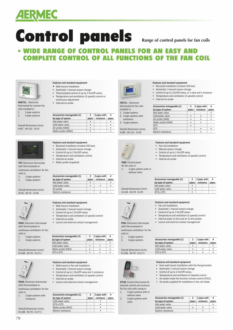
78
Control panels
Features and standard equipment• Even wall-mount installation with the fixing brackets• Automatic / manual season change • Control of up to 2 On/Off valves, • Temperature and ventilation (3 speeds) control• Air probe inside the function remote control (IFEEL)• Air probe supplied for installation in fan coil intake
Accessories manageable (1) by type of system
2 pipes
2 pipes with resistance
4 pipes
Hot water valve - - •Cold water valve • • •Electric resistance - • -
• WIDE RANGE OF CONTROL PANELS FOR AN EASY AND COMPLETE CONTROL OF ALL FUNCTIONS OF THE FAN COIL
Features and standard equipment • Wall-mount installation• Automatic / manual season change • Control of up to 2 On/Off valves • Temperature and ventilation (3 speeds) control• Internal air probe• Louvre and external contact management
Accessories manageable (1) by type of system
2 pipes
2 pipes with resistance
4 pipes
Hot water valve - - •Cold water valve • • •Water probe (SW3) • • •SIT3 e SIT5 • • •
Features and standard equipment • Fan coil installation• Automatic / manual season change • Control of up to 2 On/Off valves • Temperature and ventilation (3 speeds) control• Internal water (2.5m) and air (2.3m) probes• Louvre and external contact management
Accessories manageable (1) by type of system
2 pipes
2 pipes with resistance
4 pipes
Hot water valve • - •Cold water valve • • •SIT3 e SIT5 • • •
Accessories manageable (1) by type of system
2 pipes
2 pipes with resistance
4 pipes
Hot water valve - - •Cold water valve • • •Air probe (SWA) • • •Water probe (SWA) • • -SIT3 • - -SIT5 - • •Electric resistance - • -
Features and standard equipment • Recessed installation (module 503 box)• Automatic / manual season change • Control of up to 2 On/Off valves, or 1 valve and 1 resistance• Temperature and ventilation (3 speeds) control• Internal air probe
Features and standard equipment • Wall-mount or fan coil installation • Automatic / manual season change • Control of up to 1 On/Off valve and 1 resistance• Temperature and ventilation (3 speeds) control• Internal air probe• Louvre and external contact management
Accessories manageable (1) by type of system
2 pipes
2 pipes with resistance
4 pipes
Cold water valve - • -SIT3 e SIT5 - • -Water probe (SW3) - • -Electric resistance - • -
Features and standard equipment • Fan coil installation• Manual season change • Control of up to 1 On/Off valve, • Temperature and ventilation (3 speeds) control• Internal air probe
Accessories manageable (1) by type of system
2 pipes
2 pipes with resistance
4 pipes
Hot water valve • - -Cold water valve • - -SIT3 e SIT5 • - -
Features and standard equipment• Wall-mount installation• Automatic / manual season change • Thermostated control of up to 2 On/Off valves • Temperature and ventilation (3 speeds) control or
continuous adjustment• Internal air probe
Accessories manageable (1) by type of system
2 pipes
2 pipes with resistance
4 pipes
Hot water valve • - •Cold water valve • - •Air probe (SWAI) • - •Water probe (SWAI) • - •
Features and standard equipment• Recessed installation (module 503 box)• Automatic / manual season change • Control of up to 2 On/Off valves, • Temperature and ventilation control• Internal air probe• Water probe (supplied)
Accessories manageable (1) by type of system
2 pipes
2 pipes with resistance
4 pipes
Hot water valve • - •Cold water valve • • •Air probe - - -Electric resistance - • -
WMT21: Electronic thermostat for inverter fan coils installed in:1. 2-pipe systems 2. 4-pipe systems
Overall dimensions (mm):H=87 - W=132 - D=31
TPF: Electronic thermostat with thermostated or continuous ventilation for fan coils in:1. 2-pipe systems 2. 4-pipe systems
Overall dimensions (mm):H=45 - W=75 - D=46
PXAE: Electronic thermostat with thermostated or continuous ventilation for fan coils in:1. 2-pipe systems 2. 4-pipe systems
Overall dimensions (mm):H=148 - W=70 - D=27.5
PXBI: Control panel for fan coils in:1. 2-pipe systems with or
without valve
Overall dimensions (mm):H=145 - W=70 - D=29
FMT21 : Electronic thermostat for fan coils installed in:1. 2-pipe systems 2. 2-pipe systems with
resistance3. 4-pipe systems
Overall dimensions (mm):H=80 - W=113 - D=50
PXAI: Electronic thermostat with thermostated or continuous ventilation for fan coils in:1. 2-pipe systems 2. 4-pipe systems
Overall dimensions (mm):H=148 - W=70 - D=27.5
PXAR: Electronic thermostat with thermostated or continuous ventilation for fan coils in:1. 2-pipe systems with
resistance
Overall dimensions (mm):H=148 - W=70 - D=27.5
KTLM: Control thermostat kit (remote control and receiver) for fan coils with casing in:1. 2-pipe systems with or
without valve2. 4-pipe systems with
valve
Range of control panels for fan coils
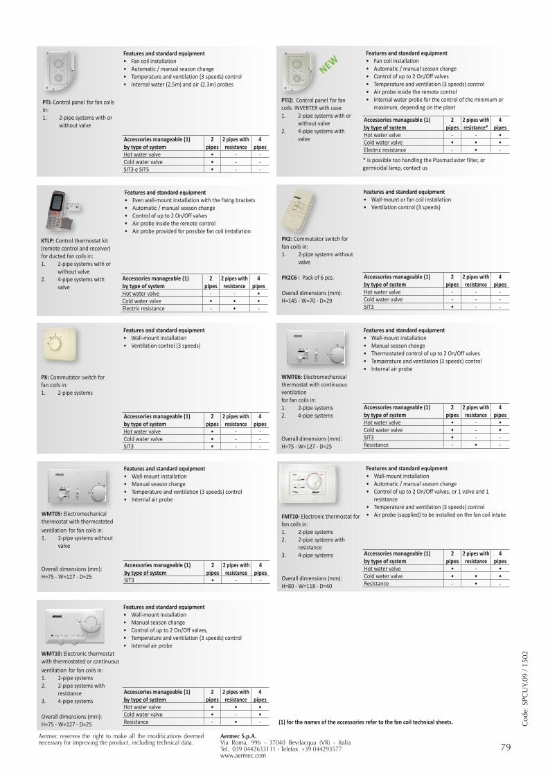
79Aermec S.p.A.Via Roma, 996 - 37040 Bevilacqua (VR) - ItaliaTel. 039 0442633111 - Telefax +39 044293577www.aermec.com
Aermec reserves the right to make all the modifications deemed necessary for improving the product, including technical data.
Cod
e: S
PCU
Y.09
/ 15
02
Features and standard equipment • Wall-mount or fan coil installation • Ventilation control (3 speeds)
Accessories manageable (1) by type of system
2 pipes
2 pipes with resistance
4 pipes
Hot water valve - - -Cold water valve - - -SIT3 • - -
Features and standard equipment• Even wall-mount installation with the fixing brackets• Automatic / manual season change • Control of up to 2 On/Off valves • Air probe inside the remote control• Air probe provided for possible fan coil installation
Accessories manageable (1) by type of system
2 pipes
2 pipes with resistance
4 pipes
Hot water valve - - •Cold water valve • • •Electric resistance - • -
KTLP: Control thermostat kit (remote control and receiver) for ducted fan coils in:1. 2-pipe systems with or
without valve2. 4-pipe systems with
valve
Features and standard equipment• Wall-mount installation• Manual season change • Thermostated control of up to 2 On/Off valves • Temperature and ventilation (3 speeds) control• Internal air probe
Accessories manageable (1) by type of system
2 pipes
2 pipes with resistance
4 pipes
Hot water valve • - •Cold water valve • - •SIT3 • - -Resistance - • -
WMT06: Electromechanical thermostat with continuous ventilationfor fan coils in:1. 2-pipe systems 2. 4-pipe systems
Overall dimensions (mm):H=75 - W=127 - D=25
Features and standard equipment• Wall-mount installation• Automatic / manual season change • Control of up to 2 On/Off valves, or 1 valve and 1
resistance• Temperature and ventilation (3 speeds) control• Air probe (supplied) to be installed on the fan coil intake
Accessories manageable (1) by type of system
2 pipes
2 pipes with resistance
4 pipes
Hot water valve • - •Cold water valve • • •Resistance - • -
FMT10: Electronic thermostat for fan coils in:1. 2-pipe systems 2. 2-pipe systems with
resistance3. 4-pipe systems
Overall dimensions (mm):H=80 - W=118 - D=40
PX2: Commutator switch for fan coils in:1. 2-pipe systems without
valve
PX2C6 : Pack of 6 pcs. Overall dimensions (mm):H=145 - W=70 - D=29
Features and standard equipment• Fan coil installation• Automatic / manual season change • Temperature and ventilation (3 speeds) control• Internal water (2.5m) and air (2.3m) probes
Accessories manageable (1) by type of system
2 pipes
2 pipes with resistance
4 pipes
Hot water valve • - -Cold water valve • - -SIT3 e SIT5 • - -
PTI: Control panel for fan coils in:1. 2-pipe systems with or
without valve
Features and standard equipment • Wall-mount installation • Ventilation control (3 speeds)
Accessories manageable (1) by type of system
2 pipes
2 pipes with resistance
4 pipes
Hot water valve • - -Cold water valve • - -SIT3 • - -
Features and standard equipment• Wall-mount installation• Manual season change • Control of up to 2 On/Off valves, • Temperature and ventilation (3 speeds) control• Internal air probe
Accessories manageable (1) by type of system
2 pipes
2 pipes with resistance
4 pipes
Hot water valve • • •Cold water valve • - •Resistance - • -
PX: Commutator switch for fan coils in:1. 2-pipe systems
Features and standard equipment• Wall-mount installation• Manual season change • Temperature and ventilation (3 speeds) control• Internal air probe
Accessories manageable (1) by type of system
2 pipes
2 pipes with resistance
4 pipes
SIT3 • - -
WMT05: Electromechanical thermostat with thermostated ventilation for fan coils in:1. 2-pipe systems without
valve
Overall dimensions (mm):H=75 - W=127 - D=25
WMT10: Electronic thermostat with thermostated or continuous ventilation for fan coils in:1. 2-pipe systems 2. 2-pipe systems with
resistance3. 4-pipe systems
Overall dimensions (mm):H=75 - W=127 - D=25 (1) for the names of the accessories refer to the fan coil technical sheets.
Features and standard equipment• Fan coil installation• Automatic / manual season change • Control of up to 2 On/Off valves • Temperature and ventilation (3 speeds) control• Air probe inside the remote control• Internal water probe for the control of the minimum or
maximum, depending on the plant
Accessories manageable (1) by type of system
2 pipes
2 pipes with resistance*
4 pipes
Hot water valve - - •Cold water valve • • •Electric resistance - • -
PTI2: Control panel for fan coils INVERTER with case:1. 2-pipe systems with or
without valve2. 4-pipe systems with
valve
NEW
* is possible too handling the Plasmacluster filter, or germicidal lamp, contact us
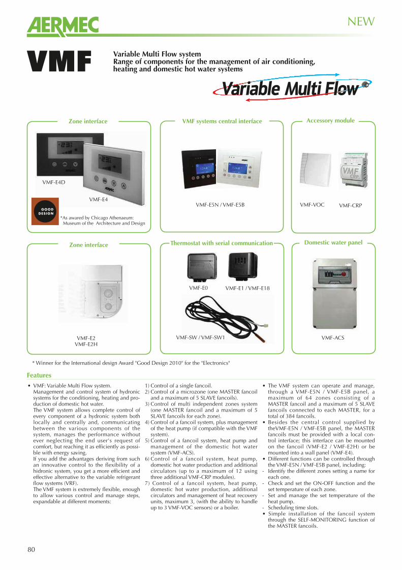
80
Variable Multi Flow systemRange of components for the management of air conditioning, heating and domestic hot water systemsVMF
• VMF: Variable Multi Flow system. Management and control system of hydronic
systems for the conditioning, heating and pro-duction of domestic hot water.
The VMF system allows complete control of every component of a hydronic system both locally and centrally and, communicating between the various components of the system, manages the performance without ever neglecting the end user's request of comfort, but reaching it as efficiently as possi-ble with energy saving.
If you add the advantages deriving from such an innovative control to the flexibility of a hidronic system, you get a more efficient and effective alternative to the variable refrigerant flow systems (VRF).
The VMF system is extremely flexible, enough to allow various control and manage steps, expandable at different moments:
1) Control of a single fancoil.2) Control of a microzone (one MASTER fancoil
and a maximum of 5 SLAVE fancoils).3) Control of multi independent zones system
(one MASTER fancoil and a maximum of 5 SLAVE fancoils for each zone).
4) Control of a fancoil system, plus management of the heat pump (if compatible with the VMF system).
5) Control of a fancoil system, heat pump and management of the domestic hot water system (VMF-ACS).
6) Control of a fancoil system, heat pump, domestic hot water production and additional circulators (up to a maximum of 12 using three additional VMF-CRP modules).
7) Control of a fancoil system, heat pump, domestic hot water production, additional circulators and management of heat recovery units, maximum 3, (with the ability to handle up to 3 VMF-VOC sensors) or a boiler.
• The VMF system can operate and manage, through a VMF-E5N / VMF-E5B panel, a maximum of 64 zones consisting of a MASTER fancoil and a maximum of 5 SLAVE fancoils connected to each MASTER, for a total of 384 fancoils.
• Besides the central control supplied by theVMF-E5N / VMF-E5B panel, the MASTER fancoils must be provided with a local con-trol interface; this interface can be mounted on the fancoil (VMF-E2 / VMF-E2H) or be mounted into a wall panel (VMF-E4).
• Different functions can be controlled through the VMF-E5N / VMF-E5B panel, including:
- Identify the different zones setting a name for each one.
- Check and set the ON-OFF function and the set temperature of each zone.
- Set and manage the set temperature of the heat pump.
- Scheduling time slots.• Simple installation of the fancoil system
through the SELF-MONITORING function of the MASTER fancoils.
Features
NEW
VMF-E5N / VMF-E5B
VMF-ACS
VMF-CRP
Zone interface
VMF-E2VMF-E2H
VMF systems central interface Accessory module
VMF-SW / VMF-SW1
VMF-E0 VMF-E1 / VMF-E18
VMF-VOC
* Winner for the International design Award "Good Design 2010" for the "Electronics"
Thermostat with serial communication
VMF-E4
*As awared by Chicago Athenaeum: Museum of the Architecture and Design
Zone interface Domestic water panel
VMF-E4D
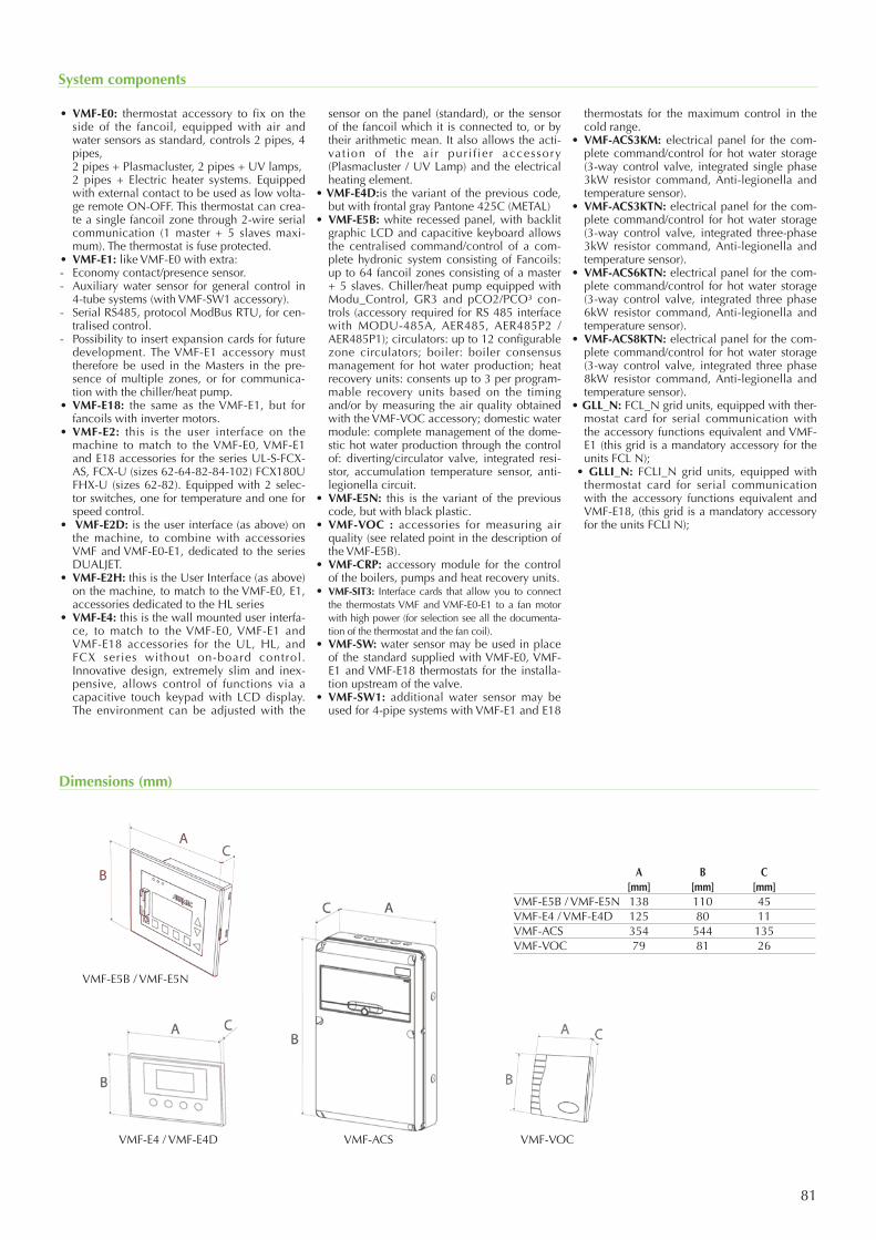
81
• VMF-E0: thermostat accessory to fix on the side of the fancoil, equipped with air and water sensors as standard, controls 2 pipes, 4 pipes,
2 pipes + Plasmacluster, 2 pipes + UV lamps, 2 pipes + Electric heater systems. Equipped
with external contact to be used as low volta-ge remote ON-OFF. This thermostat can crea-te a single fancoil zone through 2-wire serial communication (1 master + 5 slaves maxi-mum). The thermostat is fuse protected.
• VMF-E1: like VMF-E0 with extra: - Economy contact/presence sensor.- Auxiliary water sensor for general control in
4-tube systems (with VMF-SW1 accessory). - Serial RS485, protocol ModBus RTU, for cen-
tralised control.- Possibility to insert expansion cards for future
development. The VMF-E1 accessory must therefore be used in the Masters in the pre-sence of multiple zones, or for communica-tion with the chiller/heat pump.
• VMF-E18: the same as the VMF-E1, but for fancoils with inverter motors.
• VMF-E2: this is the user interface on the machine to match to the VMF-E0, VMF-E1 and E18 accessories for the series UL-S-FCX-AS, FCX-U (sizes 62-64-82-84-102) FCX180U FHX-U (sizes 62-82). Equipped with 2 selec-tor switches, one for temperature and one for speed control.
• VMF-E2D: is the user interface (as above) on the machine, to combine with accessories VMF and VMF-E0-E1, dedicated to the series DUALJET.
• VMF-E2H: this is the User Interface (as above) on the machine, to match to the VMF-E0, E1, accessories dedicated to the HL series
• VMF-E4: this is the wall mounted user interfa-ce, to match to the VMF-E0, VMF-E1 and VMF-E18 accessories for the UL, HL, and FCX series without on-board control. Innovative design, extremely slim and inex-pensive, allows control of functions via a capacitive touch keypad with LCD display. The environment can be adjusted with the
sensor on the panel (standard), or the sensor of the fancoil which it is connected to, or by their arithmetic mean. It also allows the acti-vat ion of the air puri f ier accessory (Plasmacluster / UV Lamp) and the electrical heating element.
• VMF-E4D:is the variant of the previous code, but with frontal gray Pantone 425C (METAL)
• VMF-E5B: white recessed panel, with backlit graphic LCD and capacitive keyboard allows the centralised command/control of a com-plete hydronic system consisting of Fancoils: up to 64 fancoil zones consisting of a master + 5 slaves. Chiller/heat pump equipped with Modu_Control, GR3 and pCO2/PCO³ con-trols (accessory required for RS 485 interface with MODU-485A, AER485, AER485P2 / AER485P1); circulators: up to 12 configurable zone circulators; boiler: boiler consensus management for hot water production; heat recovery units: consents up to 3 per program-mable recovery units based on the timing and/or by measuring the air quality obtained with the VMF-VOC accessory; domestic water module: complete management of the dome-stic hot water production through the control of: diverting/circulator valve, integrated resi-stor, accumulation temperature sensor, anti-legionella circuit.
• VMF-E5N: this is the variant of the previous code, but with black plastic.
• VMF-VOC : accessories for measuring air quality (see related point in the description of the VMF-E5B).
• VMF-CRP: accessory module for the control of the boilers, pumps and heat recovery units.
• VMF-SIT3: Interface cards that allow you to connect the thermostats VMF and VMF-E0-E1 to a fan motor with high power (for selection see all the documenta-tion of the thermostat and the fan coil).
• VMF-SW: water sensor may be used in place of the standard supplied with VMF-E0, VMF-E1 and VMF-E18 thermostats for the installa-tion upstream of the valve.
• VMF-SW1: additional water sensor may be used for 4-pipe systems with VMF-E1 and E18
thermostats for the maximum control in the cold range.
• VMF-ACS3KM: electrical panel for the com-plete command/control for hot water storage (3-way control valve, integrated single phase 3kW resistor command, Anti-legionella and temperature sensor).
• VMF-ACS3KTN: electrical panel for the com-plete command/control for hot water storage (3-way control valve, integrated three-phase 3kW resistor command, Anti-legionella and temperature sensor).
• VMF-ACS6KTN: electrical panel for the com-plete command/control for hot water storage (3-way control valve, integrated three phase 6kW resistor command, Anti-legionella and temperature sensor).
• VMF-ACS8KTN: electrical panel for the com-plete command/control for hot water storage (3-way control valve, integrated three phase 8kW resistor command, Anti-legionella and temperature sensor).
• GLL_N: FCL_N grid units, equipped with ther-mostat card for serial communication with the accessory functions equivalent and VMF-E1 (this grid is a mandatory accessory for the units FCL N);
• GLLI_N: FCLI_N grid units, equipped with thermostat card for serial communication with the accessory functions equivalent and VMF-E18, (this grid is a mandatory accessory for the units FCLI N);
System components
Dimensions (mm)
A B C [mm] [mm] [mm]VMF-E5B / VMF-E5N 138 110 45VMF-E4 / VMF-E4D 125 80 11VMF-ACS 354 544 135VMF-VOC 79 81 26
VMF-ACS
VMF-E5B / VMF-E5N
VMF-E4 / VMF-E4D VMF-VOC
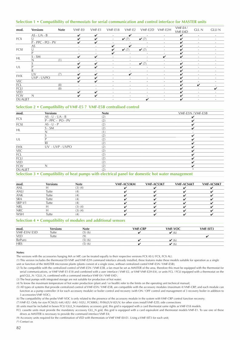
82
Notes:The versions with the accessories hanging MA or MP, can be treated equally to their respective versions FCX AS U FCX, FCX AU;(1) This version includes the thermostat E0-VMF and VMF-E2H command interface already installed, these features make these models suitable for operation as a singleunit or function of the MASTER microzone plants (plants consist of a single zone, without centralized contol VMF-E5N / VMF-E5B);(2) To be compatible with the centralized control of VMF-E5N / VMF-E5B, a fan must be set as MASTER of the area, therefore this must be equipped with the thermostat for
serial communications, or VMF VMF-E1-E18 and combined with a user interface ( VMF-E2, or VMF VMF-E2H-E4), or units FCL / FCLI equipped with a thermostat on the grid GLL_N / GLLI_N, combined with a command interface VMF-E4 / VMF-E4D ;
(3) The heat pumps with integrated storage are not suitable for production of hot water;(4) To know the maximum temperature of hot water production (plant and / or health) refer to the limits on the operating unit technical manual;(5) All types of systems that provide centralized control of VMF-E5N / VMF-E5B, are compatible with the accessory modules (maximum 4) VMF-CRP, and each module can
function as a pump controller (4 for each accessory module) or boiler control and recovery (with ON / OFF control and management of 3 recovery boiler in addition to 3 accessories VMF-VOC);
(6) The compatibility of the probe VMF-VOC is only related to the presence of the accessory module in the system with VMF-CRP control function recovery;(7) VMF-E2: Only for size FCX62U-64U-82U -84U-102U, FCXI80U, FHX62UV-82UV, for other sizes install VMF-E2D, side connections(8) units must be included in boxes FCLI GLLI_N mandatory accessory grid, this grid is equipped with a card thermostat same rights as VMF-E18 models.FCL cassette units must provide the mandatory accessory GLL_N grid, this grid is equipped with a card equivalent and thermostat models VMF-E1. To use one of these
drives as MASTER is necessary to provide the command interface VMF-E4;(9) Accessory units required for the combination of VED with thermostats or VMF VMF-E0-E1. Using a VMF-SIT3 for each unit;(*) Contact us
Selection 1 • Compatibility of thermostats for serial communication and control interface for MASTER units
Selection 2 • Compatibility of VMF-E5 7 VMF-E5B centralised control
Selection 3 • Compatibility of heat pumps with electrical panel for domestic hot water management
Selection 4 • Compatibility of modules and additional sensors
mod. Versions Note VMF-E0 VMF-E1 VMF-E18 VMF-E2 VMF-E2D VMF-E2HVMF-E4 /VMF-E4D
GLL N GLLI N
FCXAS - UA - B ✔ ✔ - ✔ - - ✔ - -U ✔ ✔ - ✔ (7) ✔ (7) - ✔ - -P - PPC - PO - PV ✔ ✔ - - - - ✔ - -
FCXIAS - - ✔ ✔ - - ✔ - -U - - ✔ ✔ (7) ✔ (7) - ✔ - -P - - ✔ - - - ✔ - -
HL S - SM ✔ ✔ - - - ✔ ✔ - -N (1) - - - - - - - - -
ULS ✔ ✔ - - ✔ (7) - ✔ - -P ✔ ✔ - - - - ✔ - -R - - - - - - ✔ - -
FHX UV (7) ✔ ✔ - ✔ - - ✔ - -UVP - UVPO ✔ ✔ - - - - ✔ - -
VEC ✔ ✔ - - - - ✔ - -FCL (8) - - - - - - ✔ ✔ -FCLI (8) - - - - - - ✔ - ✔VED ✔ ✔ - - - - ✔ - -FCW N ✔ ✔ - - - - ✔ - -DUALJET - - - - ✔ - ✔ - -
mod. Versions Note VMF-E5N / VMF-E5B
FCXAS - U - UA - B (2) ✔P - PPC - PO - PV (2) ✔
FCXI AS - U - P (2) ✔
HL S - SM (2) ✔N (1) -
ULS (2) ✔P (2) ✔RI (2) ✔
FHX UV - UVP - UVPO (2) ✔VEC (2) ✔FCL (2) ✔FCLI (2) ✔VED (2) ✔FCW N (2) ✔DUALJET (2) *
mod. Versions Note VMF-ACS3KM VMF-ACS3KT VMF-ACS6KT VMF-ACS8KTANL H (3) (4) ✔ ✔ ✔ ✔ANLI Tutte (4) ✔ ✔ ✔ ✔ANK Tutte (4) ✔ ✔ ✔ ✔SRA Tutte (4) ✔ ✔ ✔ ✔SRP-V1 Tutte (4) ✔ ✔ ✔ ✔NRL H (3) (4) ✔ ✔ ✔ ✔NRC H (3) (4) ✔ ✔ ✔ ✔WSH Tutte (4) ✔ ✔ ✔ ✔
mod. Versions Note VMF-CRP VMF-VOC VMF-SIT3VMF-E5N/ E5D Tutte (5) (6) ✔ ✔ (6) VED Tutte (9) ✔ RePuro (5) (6) ✔ ✔ (6)HRS (5) (6) ✔ ✔ (6)
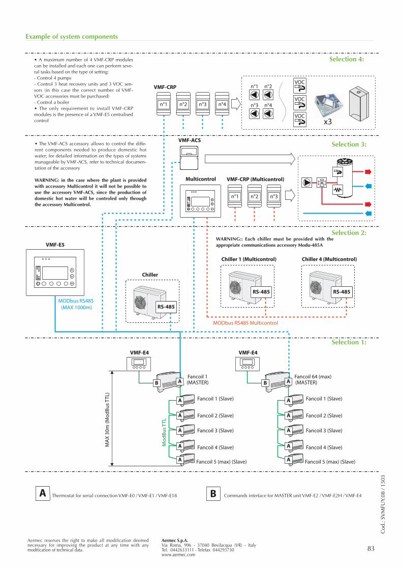
83Aermec S.p.A.Via Roma, 996 - 37040 Bevilacqua (VR) - ItalyTel. 0442633111 - Telefax 044293730www.aermec.com
Aermec reserves the right to make all modification deemed necessary for improving the product at any time with any modification of technical data.
Cod
.: SV
MFU
Y.08
/ 15
03
n°1 n°2 n°3 n°4
VMF-CRP n°1 n°2
n°3 n°4
VOC
VOC
VOCx3
VMF-ACS
Chiller
VMF-E5
B
A
A
A
A
VMF-E4
Fancoil 1(MASTER)
Fancoil 1 (Slave)
Fancoil 2 (Slave)
Fancoil 3 (Slave)
Fancoil 4 (Slave)
Fancoil 5 (max) (Slave)
B
VMF-E4
Fancoil 64 (max)(MASTER)
Fancoil 1 (Slave)
Fancoil 2 (Slave)
Fancoil 3 (Slave)
Fancoil 4 (Slave)
Fancoil 5 (max) (Slave)
A
B
MAX
30m
(Mod
Bus T
TL)
Mod
Bus T
TL
A
A A
A
A
A
A
A
MODbus RS485(MAX 1000m)
Thermostat for serial connection VMF-E0 / VMF-E1 / VMF-E18 Commands interface for MASTER unit VMF-E2 / VMF-E2H / VMF-E4
n°1 n°2 n°3 n°4
VMF-CRP n°1 n°2
n°3 n°4
VOC
VOC
VOCx3
VMF-ACS
VMF-E5
B
A
A
A
A
VMF-E4
Fancoil 1(MASTER)
Fancoil 1 (Slave)
Fancoil 2 (Slave)
Fancoil 3 (Slave)
Fancoil 4 (Slave)
Fancoil 5 (max) (Slave)
B
VMF-E4
Fancoil 64 (max)(MASTER)
Fancoil 1 (Slave)
Fancoil 2 (Slave)
Fancoil 3 (Slave)
Fancoil 4 (Slave)
Fancoil 5 (max) (Slave)
A
B
MAX
30m
(Mod
Bus T
TL)
Mod
Bus T
TL
A
A A
A
A
A
A
A
MODbus RS485 (MAX 1000m)
Chiller
RS-485RS-485
RS-485RS-485
Chiller 1 (Multicontrol)
RS-485RS-485
Chiller 4 (Multicontrol)
Multicontrol
n°1 n°2 n°3
VMF-CRP (Multicontrol)
MODbus RS485 Multicontrol
Example of system components
Selection 1:
Selection 2:
Selection 3:
Selection 4:• A maximum number of 4 VMF-CRP modules can be installed and each one can perform seve-ral tasks based on the type of setting:- Control 4 pumps- Control 3 heat recovery units and 3 VOC sen-sors (in this case the correct number of VMF-VOC accessories must be purchased)- Control a boiler• The only requirement to install VMF-CRP modules is the presence of a VMF-E5 centralised control
• The VMF-ACS accessory allows to control the diffe-rent components needed to produce domestic hot water; for detailed information on the types of systems manageable by VMF-ACS, refer to technical documen-tation of the accessory
WARNING: in the case where the plant is provided with accessory Multicontrol it will not be possible to use the accessory VMF-ACS, since the production of domestic hot water will be controled only through the accessory Multicontrol.
WARNING:: Each chiller must be provided with the appropriate communications accessory Modu-485A
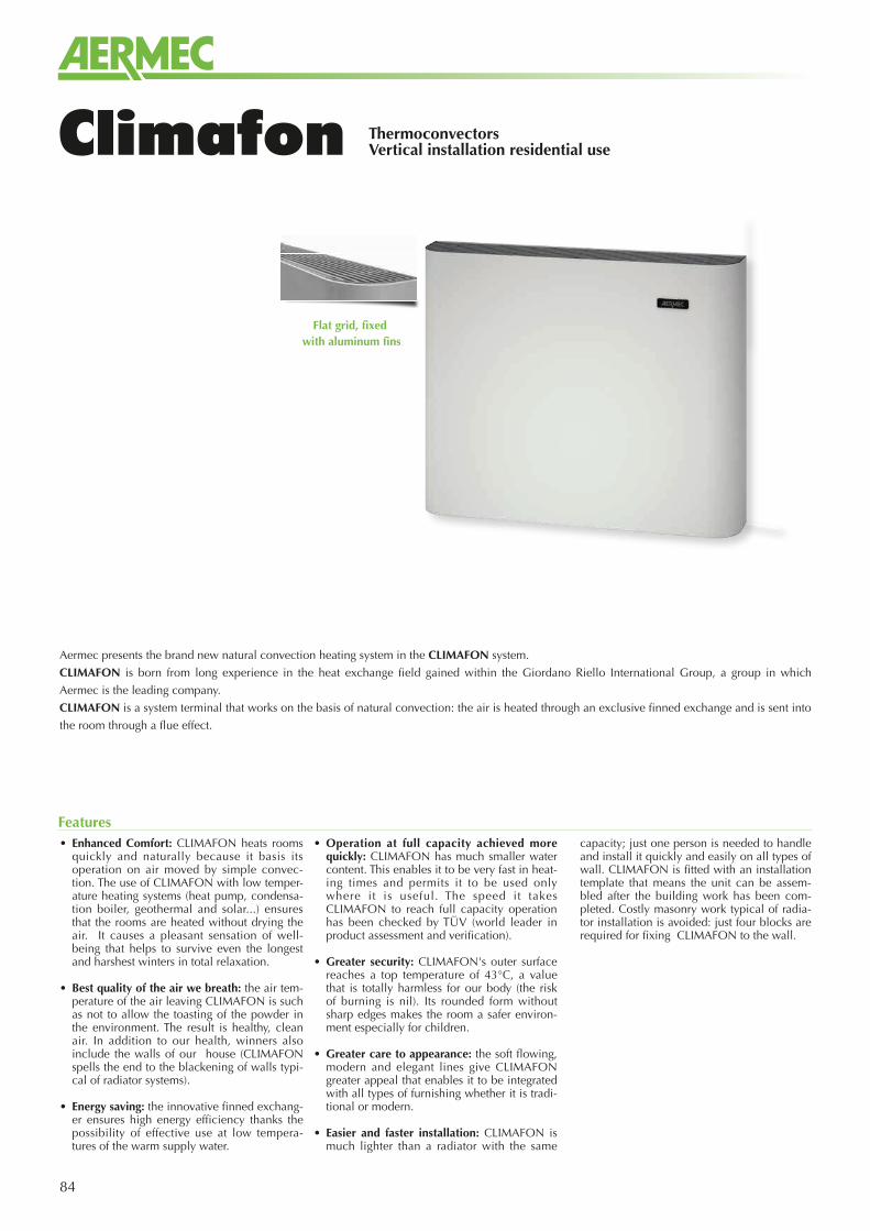
84
ThermoconvectorsVertical installation residential useClimafon
• Enhanced Comfort: CLIMAFON heats rooms quickly and naturally because it basis its operation on air moved by simple convec-tion. The use of CLIMAFON with low temper-ature heating systems (heat pump, condensa-tion boiler, geothermal and solar...) ensures that the rooms are heated without drying the air. It causes a pleasant sensation of well-being that helps to survive even the longest and harshest winters in total relaxation.
• Best quality of the air we breath: the air tem-perature of the air leaving CLIMAFON is such as not to allow the toasting of the powder in the environment. The result is healthy, clean air. In addition to our health, winners also include the walls of our house (CLIMAFON spells the end to the blackening of walls typi-cal of radiator systems).
• Energy saving: the innovative finned exchang-er ensures high energy efficiency thanks the possibility of effective use at low tempera-tures of the warm supply water.
• Operation at full capacity achieved more quickly: CLIMAFON has much smaller water content. This enables it to be very fast in heat-ing times and permits it to be used only where it is useful. The speed it takes CLIMAFON to reach full capacity operation has been checked by TÜV (world leader in product assessment and verification).
• Greater security: CLIMAFON's outer surface reaches a top temperature of 43°C, a value that is totally harmless for our body (the risk of burning is nil). Its rounded form without sharp edges makes the room a safer environ-ment especially for children.
• Greater care to appearance: the soft flowing, modern and elegant lines give CLIMAFON greater appeal that enables it to be integrated with all types of furnishing whether it is tradi-tional or modern.
• Easier and faster installation: CLIMAFON is much lighter than a radiator with the same
capacity; just one person is needed to handle and install it quickly and easily on all types of wall. CLIMAFON is fitted with an installation template that means the unit can be assem-bled after the building work has been com-pleted. Costly masonry work typical of radia-tor installation is avoided: just four blocks are required for fixing CLIMAFON to the wall.
Features
Aermec presents the brand new natural convection heating system in the CLIMAFON system.
CLIMAFON is born from long experience in the heat exchange field gained within the Giordano Riello International Group, a group in which
Aermec is the leading company.
CLIMAFON is a system terminal that works on the basis of natural convection: the air is heated through an exclusive finned exchange and is sent into
the room through a flue effect.
Flat grid, fixed with aluminum fins
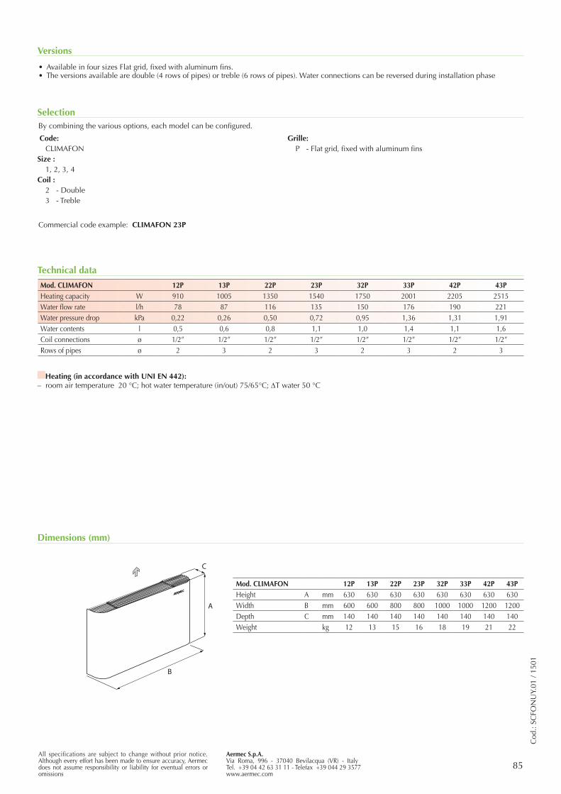
85Aermec S.p.A.Via Roma, 996 - 37040 Bevilacqua (VR) - ItalyTel. +39 04 42 63 31 11 - Telefax +39 044 29 3577www.aermec.com
All specifications are subject to change without prior notice. Although every effort has been made to ensure accuracy, Aermec does not assume responsibility or liability for eventual errors or omissions
Cod
.: SC
FON
UY.
01 /
1501
A
C
B
Versions
Technical data
Dimensions (mm)
• Available in four sizes Flat grid, fixed with aluminum fins.• The versions available are double (4 rows of pipes) or treble (6 rows of pipes). Water connections can be reversed during installation phase
Mod. CLIMAFON 12P 13P 22P 23P 32P 33P 42P 43PHeating capacity W 910 1005 1350 1540 1750 2001 2205 2515Water flow rate l/h 78 87 116 135 150 176 190 221Water pressure drop kPa 0,22 0,26 0,50 0,72 0,95 1,36 1,31 1,91Water contents l 0,5 0,6 0,8 1,1 1,0 1,4 1,1 1,6Coil connections ø 1/2” 1/2” 1/2” 1/2” 1/2” 1/2” 1/2” 1/2”Rows of pipes ø 2 3 2 3 2 3 2 3
Mod. CLIMAFON 12P 13P 22P 23P 32P 33P 42P 43PHeight A mm 630 630 630 630 630 630 630 630Width B mm 600 600 800 800 1000 1000 1200 1200Depth C mm 140 140 140 140 140 140 140 140Weight kg 12 13 15 16 18 19 21 22
Heating (in accordance with UNI EN 442): – room air temperature 20 °C; hot water temperature (in/out) 75/65°C; DT water 50 °C
By combining the various options, each model can be configured.
Commercial code example: CLIMAFON 23P
Selection
Code:CLIMAFON
Size :1, 2, 3, 4
Coil :2 - Double3 - Treble
Grille:P - Flat grid, fixed with aluminum fins
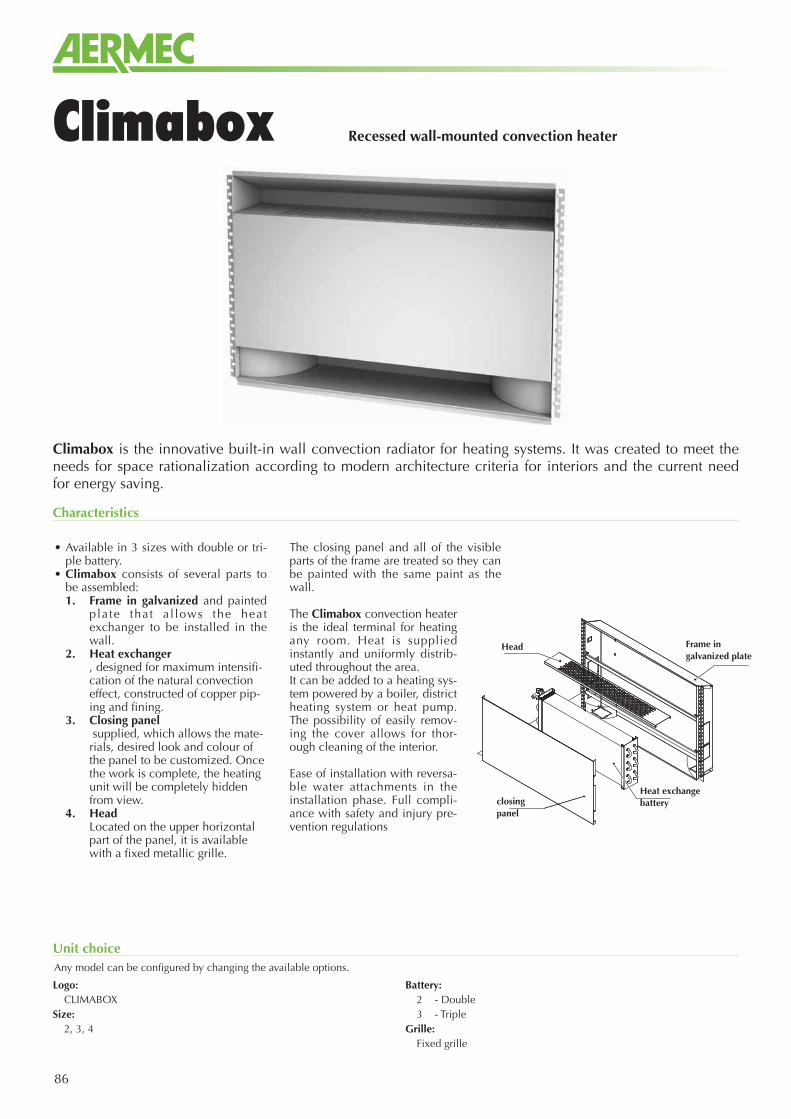
86
Climabox is the innovative built-in wall convection radiator for heating systems. It was created to meet the needs for space rationalization according to modern architecture criteria for interiors and the current need for energy saving.
Recessed wall-mounted convection heaterClimabox
• Available in 3 sizes with double or tri-ple battery.
• Climabox consists of several parts to be assembled:1. Frame in galvanized and painted
plate that a l lows the heat exchanger to be installed in the wall.
2. Heat exchanger , designed for maximum intensifi-cation of the natural convection effect, constructed of copper pip-ing and fining.
3. Closing panel supplied, which allows the mate-rials, desired look and colour of the panel to be customized. Once the work is complete, the heating unit will be completely hidden from view.
4. Head Located on the upper horizontal part of the panel, it is available with a fixed metallic grille.
The closing panel and all of the visible parts of the frame are treated so they can be painted with the same paint as the wall.
The Climabox convection heater is the ideal terminal for heating any room. Heat is supplied instantly and uniformly distrib-uted throughout the area.It can be added to a heating sys-tem powered by a boiler, district heating system or heat pump. The possibility of easily remov-ing the cover allows for thor-ough cleaning of the interior.
Ease of installation with reversa-ble water attachments in the installation phase. Full compli-ance with safety and injury pre-vention regulations
Characteristics
Any model can be configured by changing the available options.
Unit choice
Logo:CLIMABOX
Size:2, 3, 4
Battery:2 - Double3 - Triple
Grille:Fixed grille
Frame in galvanized plate
Head
Heat exchange batteryclosing
panel