Embed Size (px)
Citation preview

V A L V E S F O R H E A T I N G S Y S T E M 33
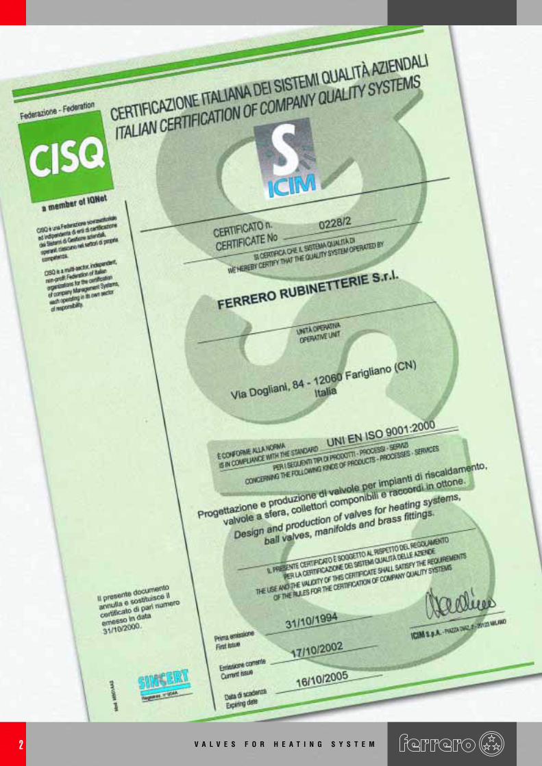
V A L V E S F O R H E A T I N G S Y S T E M2
V A L V E S F O R H E A T I N G S Y S T E M 3
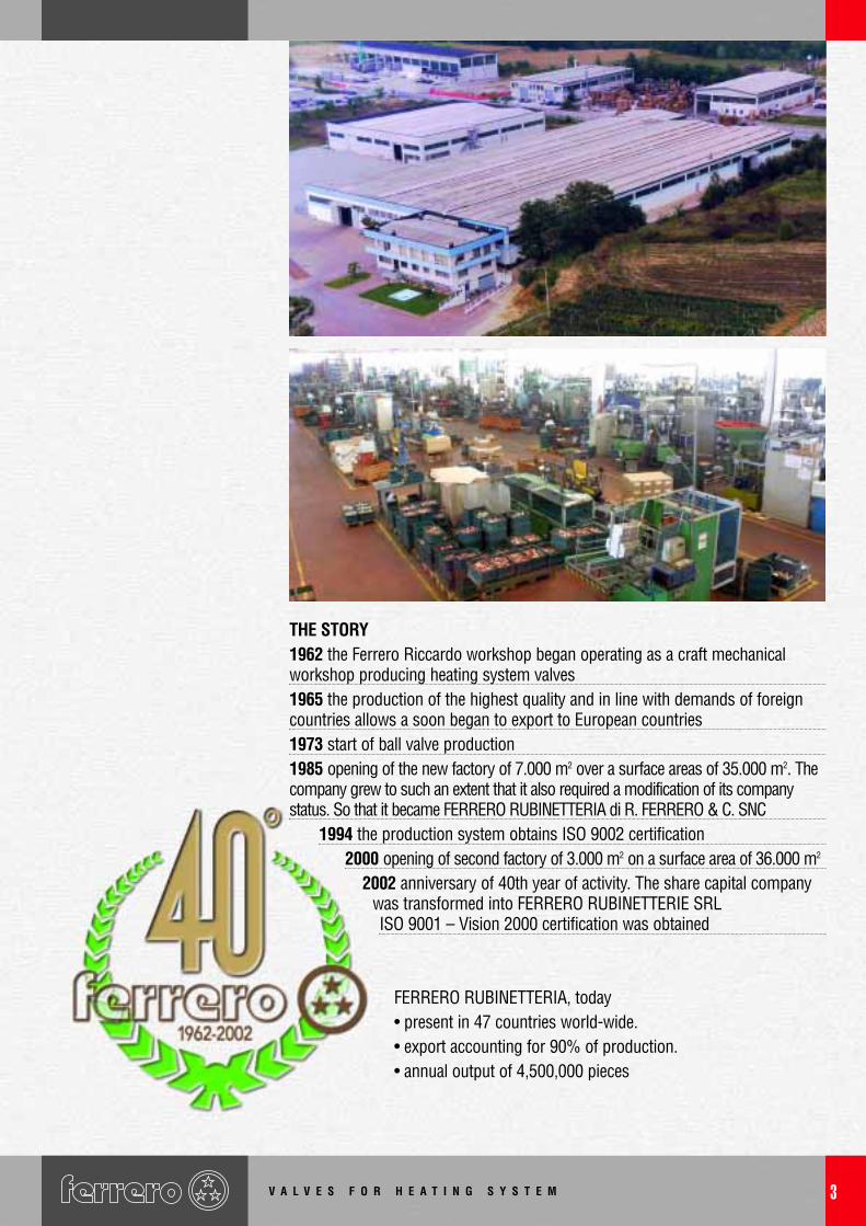
THE STORY1962 the Ferrero Riccardo workshop began operating as a craft mechanicalworkshop producing heating system valves1965 the production of the highest quality and in line with demands of foreigncountries allows a soon began to export to European countries1973 start of ball valve production1985 opening of the new factory of 7.000 m2 over a surface areas of 35.000 m2. Thecompany grew to such an extent that it also required a modification of its companystatus. So that it became FERRERO RUBINETTERIA di R. FERRERO & C. SNC
1994 the production system obtains ISO 9002 certification2000 opening of second factory of 3.000 m2 on a surface area of 36.000 m2
2002 anniversary of 40th year of activity. The share capital companywas transformed into FERRERO RUBINETTERIE SRLISO 9001 – Vision 2000 certification was obtained
FERRERO RUBINETTERIA, today• present in 47 countries world-wide.• export accounting for 90% of production.• annual output of 4,500,000 pieces
V A L V E S F O R H E A T I N G S Y S T E M4
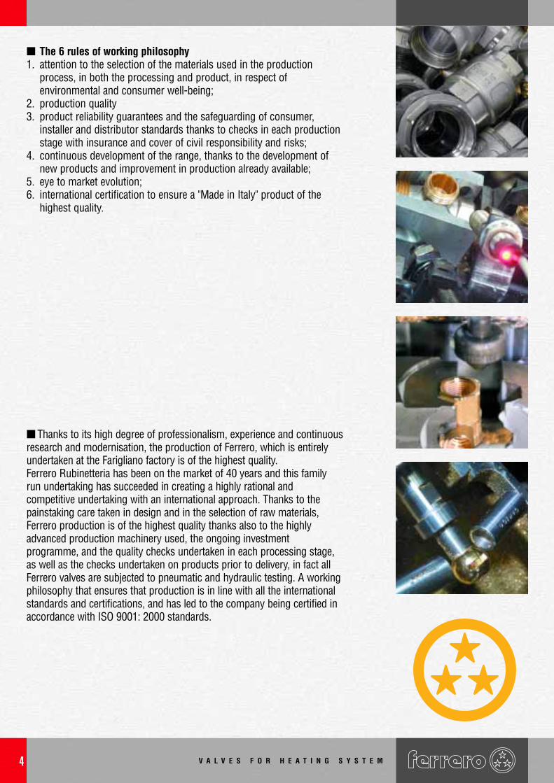
■ Thanks to its high degree of professionalism, experience and continuousresearch and modernisation, the production of Ferrero, which is entirelyundertaken at the Farigliano factory is of the highest quality.Ferrero Rubinetteria has been on the market of 40 years and this familyrun undertaking has succeeded in creating a highly rational andcompetitive undertaking with an international approach. Thanks to thepainstaking care taken in design and in the selection of raw materials,Ferrero production is of the highest quality thanks also to the highlyadvanced production machinery used, the ongoing investmentprogramme, and the quality checks undertaken in each processing stage,as well as the checks undertaken on products prior to delivery, in fact allFerrero valves are subjected to pneumatic and hydraulic testing. A workingphilosophy that ensures that production is in line with all the internationalstandards and certifications, and has led to the company being certified inaccordance with ISO 9001: 2000 standards.
■ The 6 rules of working philosophy1. attention to the selection of the materials used in the production
process, in both the processing and product, in respect ofenvironmental and consumer well-being;
2. production quality3. product reliability guarantees and the safeguarding of consumer,
installer and distributor standards thanks to checks in each productionstage with insurance and cover of civil responsibility and risks;
4. continuous development of the range, thanks to the development ofnew products and improvement in production already available;
5. eye to market evolution;6. international certification to ensure a "Made in Italy" product of the
highest quality.
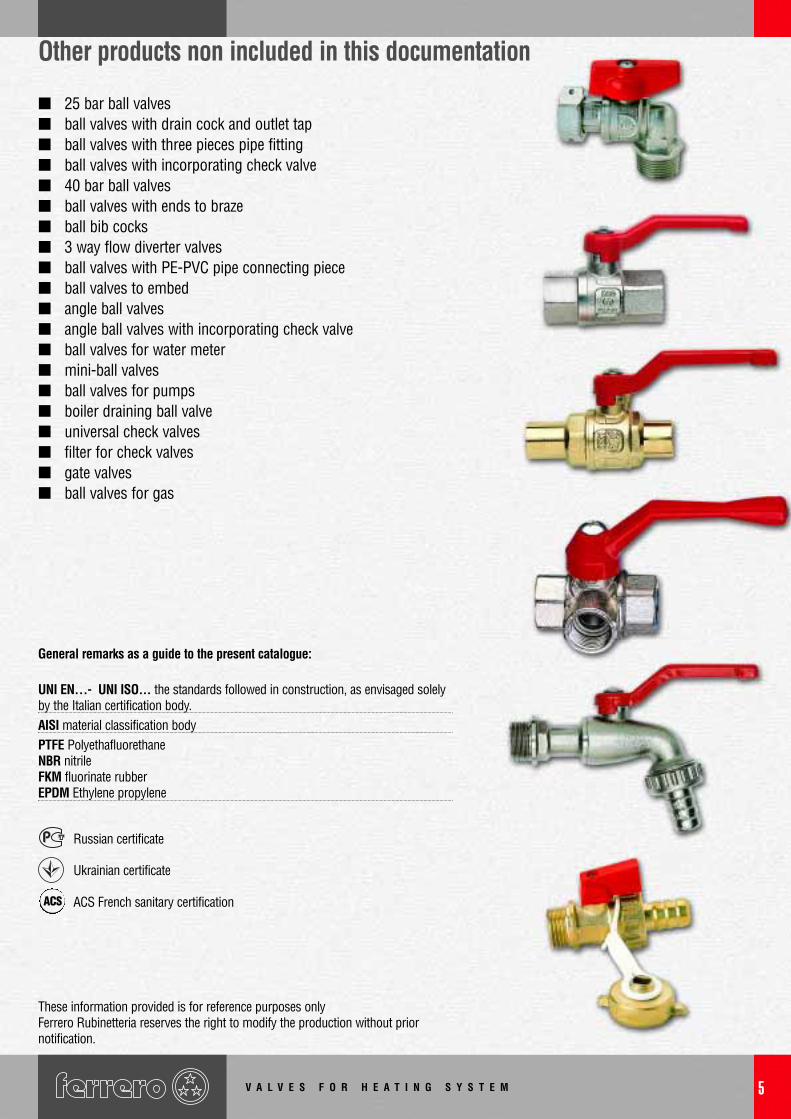
■ 25 bar ball valves■ ball valves with drain cock and outlet tap■ ball valves with three pieces pipe fitting■ ball valves with incorporating check valve■ 40 bar ball valves■ ball valves with ends to braze■ ball bib cocks■ 3 way flow diverter valves■ ball valves with PE-PVC pipe connecting piece■ ball valves to embed■ angle ball valves■ angle ball valves with incorporating check valve■ ball valves for water meter■ mini-ball valves■ ball valves for pumps■ boiler draining ball valve■ universal check valves■ filter for check valves■ gate valves■ ball valves for gas
Other products non included in this documentation
General remarks as a guide to the present catalogue:
UNI EN…- UNI ISO... the standards followed in construction, as envisaged solelyby the Italian certification body.AISI material classification bodyPTFE PolyethafluorethaneNBR nitrileFKM fluorinate rubberEPDM Ethylene propylene
Russian certificate
Ukrainian certificate
ACS French sanitary certification
These information provided is for reference purposes onlyFerrero Rubinetteria reserves the right to modify the production without priornotification.
V A L V E S F O R H E A T I N G S Y S T E M 5
ACS
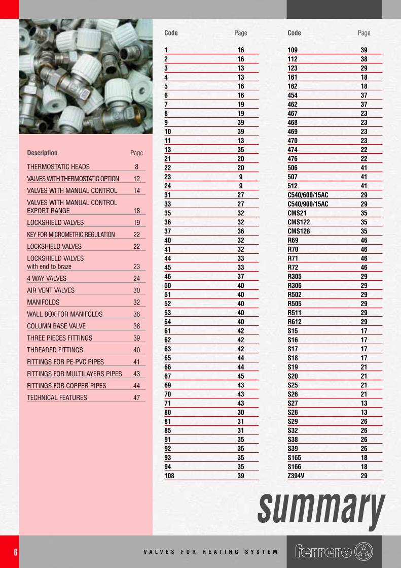
Description Page
THERMOSTATIC HEADS 8
VALVES WITH THERMOSTATIC OPTION 12
VALVES WITH MANUAL CONTROL 14
VALVES WITH MANUAL CONTROLEXPORT RANGE 18
LOCKSHIELD VALVES 19
KEY FOR MICROMETRIC REGULATION 22
LOCKSHIELD VALVES 22
LOCKSHIELD VALVESwith end to braze 23
4 WAY VALVES 24
AIR VENT VALVES 30
MANIFOLDS 32
WALL BOX FOR MANIFOLDS 36
COLUMN BASE VALVE 38
THREE PIECES FITTINGS 39
THREADED FITTINGS 40
FITTINGS FOR PE-PVC PIPES 41
FITTINGS FOR MULTILAYERS PIPES 43
FITTINGS FOR COPPER PIPES 44
TECHNICAL FEATURES 47
Code Page
1 162 163 134 135 166 167 198 199 3910 3911 1313 3521 2022 2023 924 931 2733 2735 3236 3237 3640 3241 3244 3345 3346 3750 4051 4052 4053 4054 4061 4262 4263 4265 4466 4467 4569 4370 4371 4380 3081 3185 3191 3592 3593 3594 35108 39
Code Page
109 39112 38123 29161 18162 18454 37462 37467 23468 23469 23470 23474 22476 22506 41507 41512 41C540/600/15AC 29C540/900/15AC 29CMS21 35CMS122 35CMS128 35R69 46R70 46R71 46R72 46R305 29R306 29R502 29R505 29R511 29R612 29S15 17S16 17S17 17S18 17S19 21S20 21S25 21S26 21S27 13S28 13S29 26S32 26S38 26S39 26S165 18S166 18Z394V 29
V A L V E S F O R H E A T I N G S Y S T E M6
summary
V A L V E S F O R H E A T I N G S Y S T E M 7
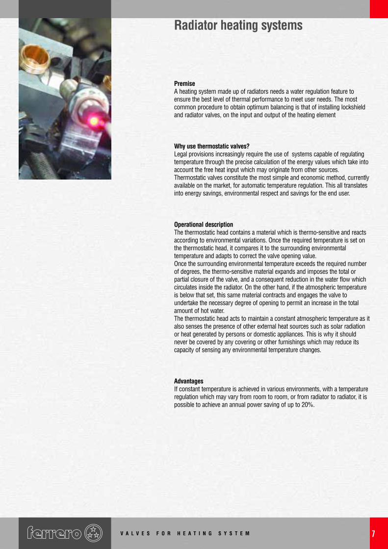
PremiseA heating system made up of radiators needs a water regulation feature toensure the best level of thermal performance to meet user needs. The mostcommon procedure to obtain optimum balancing is that of installing lockshieldand radiator valves, on the input and output of the heating element
Why use thermostatic valves?Legal provisions increasingly require the use of systems capable of regulatingtemperature through the precise calculation of the energy values which take intoaccount the free heat input which may originate from other sources.Thermostatic valves constitute the most simple and economic method, currentlyavailable on the market, for automatic temperature regulation. This all translatesinto energy savings, environmental respect and savings for the end user.
Operational description The thermostatic head contains a material which is thermo-sensitive and reactsaccording to environmental variations. Once the required temperature is set onthe thermostatic head, it compares it to the surrounding environmentaltemperature and adapts to correct the valve opening value.Once the surrounding environmental temperature exceeds the required numberof degrees, the thermo-sensitive material expands and imposes the total orpartial closure of the valve, and a consequent reduction in the water flow whichcirculates inside the radiator. On the other hand, if the atmospheric temperatureis below that set, this same material contracts and engages the valve toundertake the necessary degree of opening to permit an increase in the totalamount of hot water.The thermostatic head acts to maintain a constant atmospheric temperature as italso senses the presence of other external heat sources such as solar radiationor heat generated by persons or domestic appliances. This is why it shouldnever be covered by any covering or other furnishings which may reduce itscapacity of sensing any environmental temperature changes.
Advantages If constant temperature is achieved in various environments, with a temperatureregulation which may vary from room to room, or from radiator to radiator, it ispossible to achieve an annual power saving of up to 20%.
Radiator heating systems
V A L V E S F O R H E A T I N G S Y S T E M8
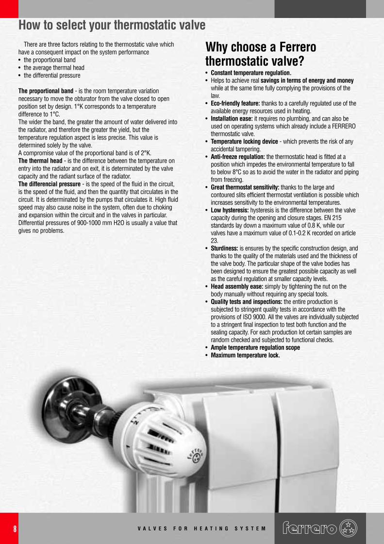
How to select your thermostatic valveThere are three factors relating to the thermostatic valve which
have a consequent impact on the system performance• the proportional band• the average thermal head• the differential pressure
The proportional band - is the room temperature variationnecessary to move the obturator from the valve closed to openposition set by design. 1°K corresponds to a temperaturedifference to 1°C.The wider the band, the greater the amount of water delivered intothe radiator, and therefore the greater the yield, but thetemperature regulation aspect is less precise. This value isdetermined solely by the valve.A compromise value of the proportional band is of 2°K. The thermal head - is the difference between the temperature onentry into the radiator and on exit, it is determinated by the valvecapacity and the radiant surface of the radiator.The differencial pressure - is the speed of the fluid in the circuit,is the speed of the fluid, and then the quantity that circulates in thecircuit. It is determinated by the pumps that circulates it. High fluidspeed may also cause noise in the system, often due to chokingand expansion within the circuit and in the valves in particular.Differential pressures of 900-1000 mm H2O is usually a value thatgives no problems.
Why choose a Ferrerothermostatic valve?• Constant temperature regulation.• Helps to achieve real savings in terms of energy and money
while at the same time fully complying the provisions of thelaw.
• Eco-friendly feature: thanks to a carefully regulated use of theavailable energy resources used in heating.
• Installation ease: it requires no plumbing, and can also beused on operating systems which already include a FERREROthermostatic valve.
• Temperature locking device - which prevents the risk of anyaccidental tampering.
• Anti-freeze regulation: the thermostatic head is fitted at aposition which impedes the environmental temperature to fallto below 8°C so as to avoid the water in the radiator and pipingfrom freezing.
• Great thermostat sensitivity: thanks to the large andcontoured slits efficient thermostat ventilation is possible whichincreases sensitivity to the environmental temperatures.
• Low hysteresis: hysteresis is the difference between the valvecapacity during the opening and closure stages. EN 215standards lay down a maximum value of 0.8 K, while ourvalves have a maximum value of 0.1-0.2 K recorded on article23.
• Sturdiness: is ensures by the specific construction design, andthanks to the quality of the materials used and the thickness ofthe valve body. The particular shape of the valve bodies hasbeen designed to ensure the greatest possible capacity as wellas the careful regulation at smaller capacity levels.
• Head assembly ease: simply by tightening the nut on thebody manually without requiring any special tools.
• Quality tests and inspections: the entire production issubjected to stringent quality tests in accordance with theprovisions of ISO 9000. All the valves are individually subjectedto a stringent final inspection to test both function and thesealing capacity. For each production lot certain samples arerandom checked and subjected to functional checks.
• Ample temperature regulation scope• Maximum temperature lock.
V A L V E S F O R H E A T I N G S Y S T E M 9
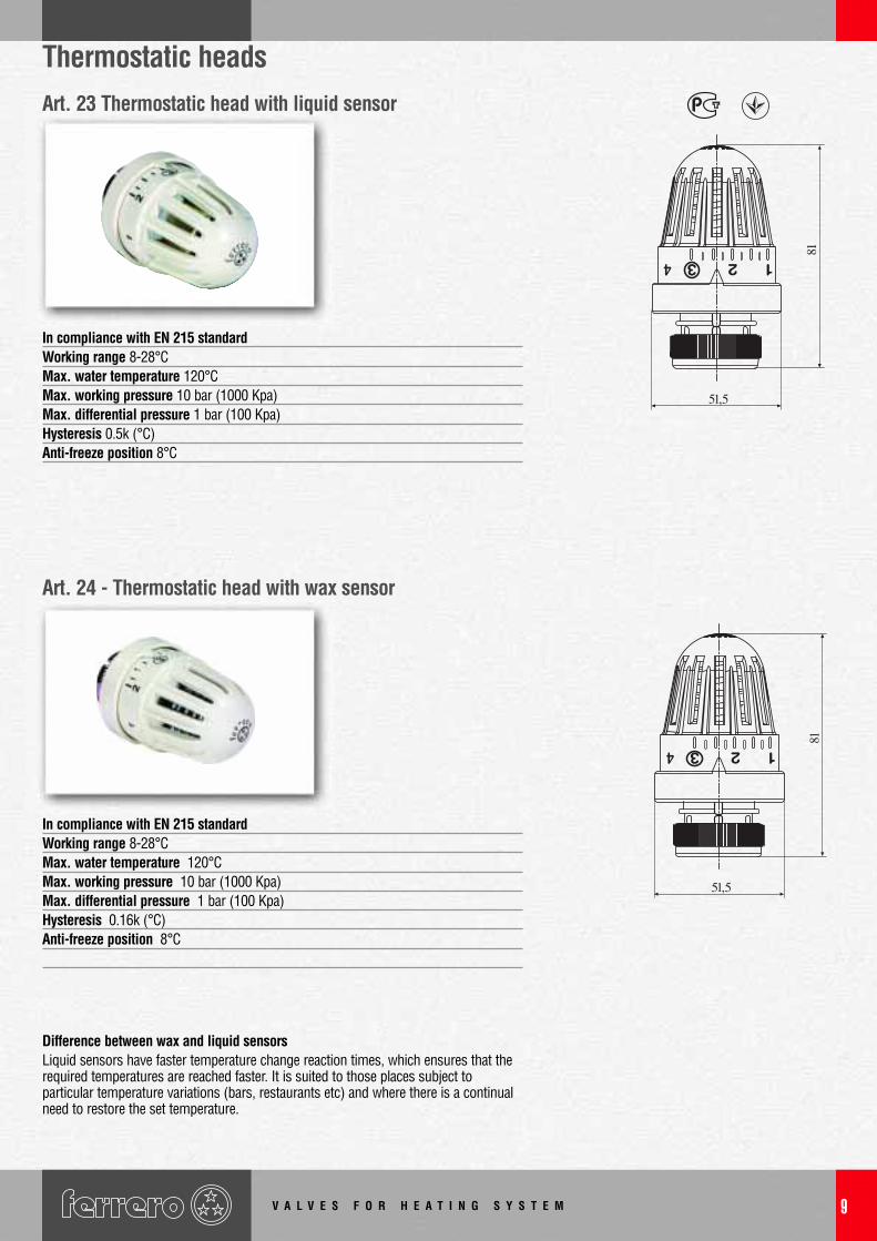
Thermostatic heads
In compliance with EN 215 standardWorking range 8-28°CMax. water temperature 120°CMax. working pressure 10 bar (1000 Kpa)Max. differential pressure 1 bar (100 Kpa)Hysteresis 0.16k (°C)Anti-freeze position 8°C
Difference between wax and liquid sensorsLiquid sensors have faster temperature change reaction times, which ensures that therequired temperatures are reached faster. It is suited to those places subject toparticular temperature variations (bars, restaurants etc) and where there is a continualneed to restore the set temperature.
In compliance with EN 215 standardWorking range 8-28°CMax. water temperature 120°CMax. working pressure 10 bar (1000 Kpa)Max. differential pressure 1 bar (100 Kpa)Hysteresis 0.5k (°C)Anti-freeze position 8°C
Art. 23 Thermostatic head with liquid sensor
Art. 24 - Thermostatic head with wax sensor
V A L V E S F O R H E A T I N G S Y S T E M10
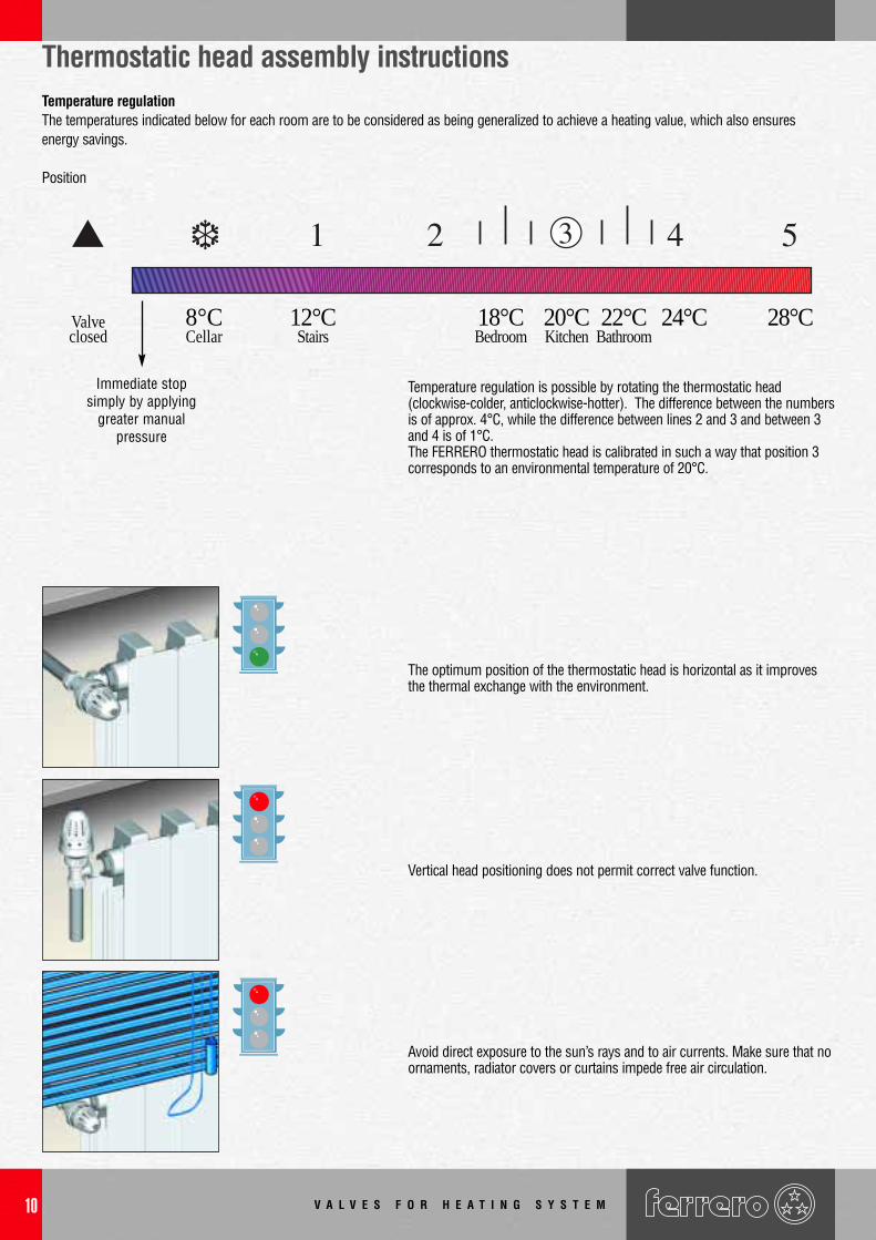
Thermostatic head assembly instructionsTemperature regulationThe temperatures indicated below for each room are to be considered as being generalized to achieve a heating value, which also ensuresenergy savings.
Position
❆▲ ●
Temperature regulation is possible by rotating the thermostatic head(clockwise-colder, anticlockwise-hotter). The difference between the numbersis of approx. 4°C, while the difference between lines 2 and 3 and between 3and 4 is of 1°C.The FERRERO thermostatic head is calibrated in such a way that position 3corresponds to an environmental temperature of 20°C.
The optimum position of the thermostatic head is horizontal as it improvesthe thermal exchange with the environment.
Vertical head positioning does not permit correct valve function.
Avoid direct exposure to the sun’s rays and to air currents. Make sure that noornaments, radiator covers or curtains impede free air circulation.
Immediate stopsimply by applying
greater manualpressure
Valveclosed
8°CCellar
12°CStairs
18°CBedroom
20°CKitchen
22°CBathroom
24°C 28°C
V A L V E S F O R H E A T I N G S Y S T E M 11
Thermostatic head assembly instructions• Dismantle the valve hand-wheel• Unscrew the manual control fixture nut (A) using a spanner of 15 mm.• Turn the thermostatic head to position no. 5• Insert the head onto the body rotating only the fixture nut (C) of the head.• Tighten the thermostatic head on the thread keeping the indicator (B) high rotating only
the fixture nut (C) of the head.• Regulation is possible by rotating the head to a position which corresponds to the
desired temperature.
1/2
“
Temperature lockTemperature locking device to prevent the risk of any accidental tampering. It isengaged by pressing the ring which positions the indicator in one’s own direction.
Head calibrationThe thermostat is regulated in such a way that position 3, under normal conditionscorresponds to an atmospheric temperature of about 20°C. This regulation may notcorrespond in the event of particular installation conditions and it may therefore benecessary to re-regulate the head. To calibrate the head proceed as follows:• measure the actual temperature on the thermostat• rotate the thermostat to position 5 and dismantlet from the body unscrewing the fixture
nut.• using a screwdriver, undertake to tighten the central screw to increase and loosen the
screw to reduce the temperature. 1/4 of a turn corresponds to 1°C. In order to avoidexcessively influence the anti-freeze position, do not regulate by over 1/4 of a turn.
• re-assemble the head onto the valve.
APosition indicator B
Fixture nut C
12
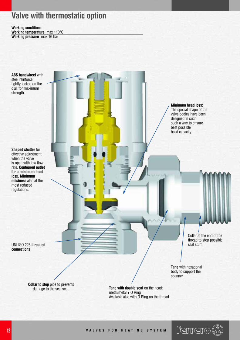
Valve with thermostatic optionWorking conditionsWorking temperature max 110°CWorking pressure max 16 bar
Tang with double seal on the head: metal/metal + O RingAvailable also with O Ring on the thread
Collar to stop pipe to preventsdamage to the seal seat.
UNI ISO 228 threadedconnections
Shaped shutter foreffective adjustmentwhen the valve is open with low flowrate. Contoured outletfor a minimum headloss. Minimumnoisiness also at themost reduced regulations.
ABS handwheel withsteel reinforcetightly locked on thedial, for maximumstrength.
V A L V E S F O R H E A T I N G S Y S T E M
Minimum head loss: The special shape of thevalve bodies have beendesigned in suchsuch a way to ensurebest possiblehead capacity.
Tang with hexagonalbody to support thespanner
Collar at the end of thethread to stop possibleseal stuff.
V A L V E S F O R H E A T I N G S Y S T E M 13
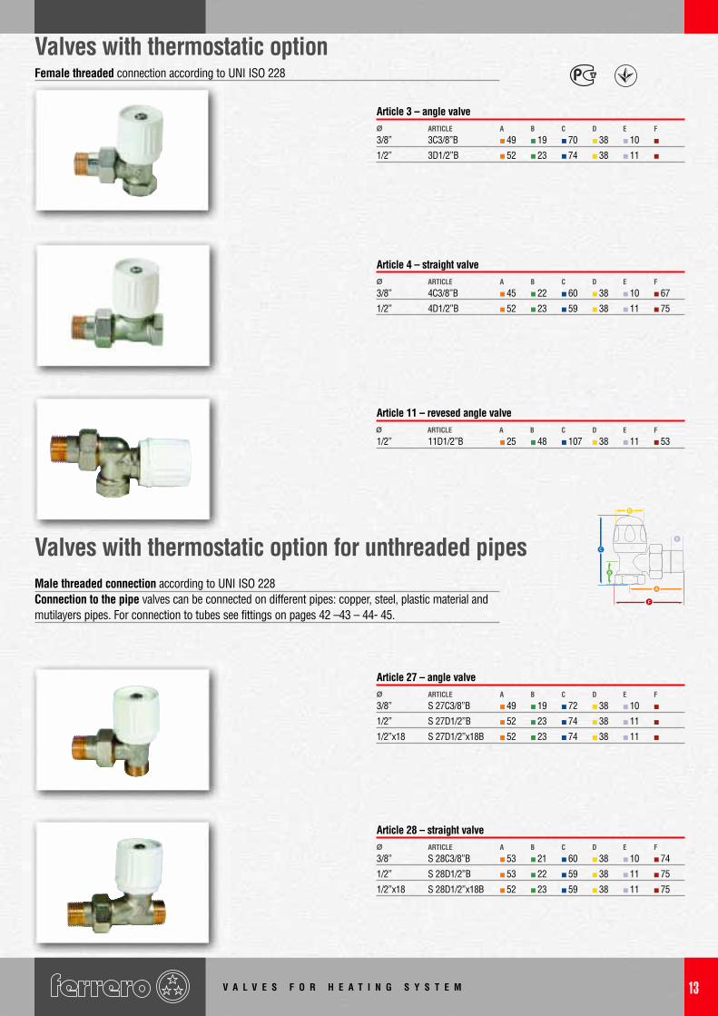
Valves with thermostatic option
Valves with thermostatic option for unthreaded pipes
3/8” 3C3/8”B 49 19 70 38 10
1/2” 3D1/2”B 52 23 74 38 11
Ø ARTICLE CBA D E F
Article 3 – angle valve
3/8” 4C3/8”B 45 22 60 38 10 67
1/2” 4D1/2”B 52 23 59 38 11 75
Ø ARTICLE CBA D E F
Article 4 – straight valve
1/2” 11D1/2”B 25 48 107 38 11 53Ø ARTICLE CBA D E F
Article 11 – revesed angle valve
3/8” S 27C3/8”B 49 19 72 38 10
1/2” S 27D1/2”B 52 23 74 38 11
1/2”x18 S 27D1/2”x18B 52 23 74 38 11
Ø ARTICLE CBA D E F
Article 27 – angle valve
3/8” S 28C3/8”B 53 21 60 38 10 74
1/2” S 28D1/2”B 53 22 59 38 11 75
1/2”x18 S 28D1/2”x18B 52 23 59 38 11 75
Ø ARTICLE CBA D E F
Article 28 – straight valve
Male threaded connection according to UNI ISO 228Connection to the pipe valves can be connected on different pipes: copper, steel, plastic material andmutilayers pipes. For connection to tubes see fittings on pages 42 –43 – 44- 45.
Female threaded connection according to UNI ISO 228
C
E
F
V A L V E S F O R H E A T I N G S Y S T E M14
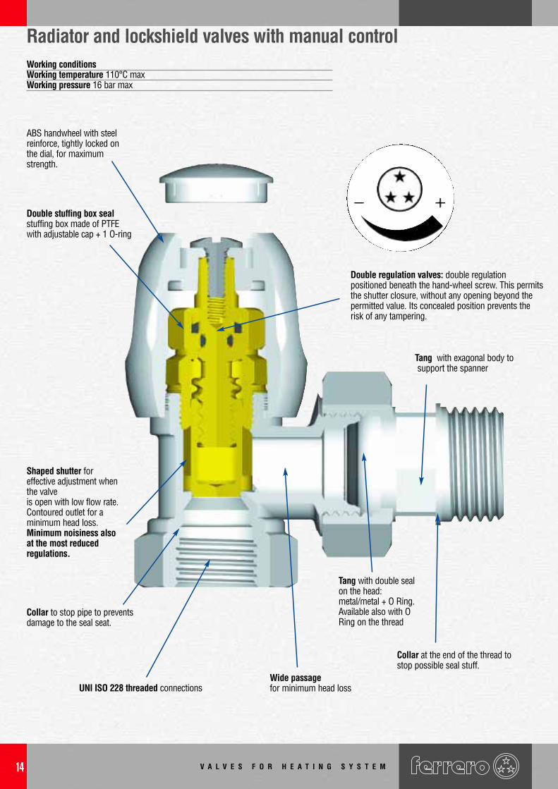
Radiator and lockshield valves with manual controlWorking conditionsWorking temperature 110°C maxWorking pressure 16 bar max
Double regulation valves: double regulationpositioned beneath the hand-wheel screw. This permitsthe shutter closure, without any opening beyond thepermitted value. Its concealed position prevents therisk of any tampering.
Shaped shutter foreffective adjustment whenthe valve is open with low flow rate.Contoured outlet for a minimum head loss.Minimum noisiness alsoat the most reduced regulations.
UNI ISO 228 threaded connections
Collar to stop pipe to preventsdamage to the seal seat.
Wide passagefor minimum head loss
Double stuffing box sealstuffing box made of PTFEwith adjustable cap + 1 O-ring
ABS handwheel with steelreinforce, tightly locked onthe dial, for maximumstrength.
Collar at the end of the thread tostop possible seal stuff.
Tang with exagonal body tosupport the spanner
Tang with double sealon the head:metal/metal + O Ring.Available also with ORing on the thread
V A L V E S F O R H E A T I N G S Y S T E M 15
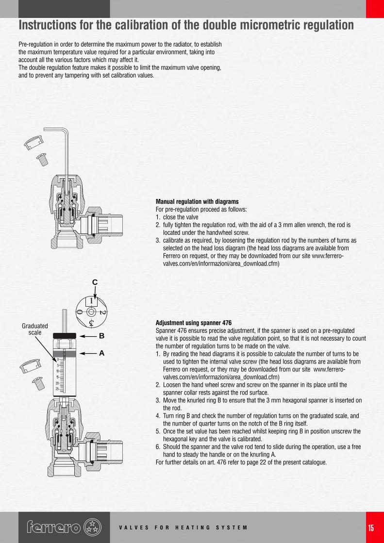
Instructions for the calibration of the double micrometric regulationPre-regulation in order to determine the maximum power to the radiator, to establishthe maximum temperature value required for a particular environment, taking intoaccount all the various factors which may affect it.The double regulation feature makes it possible to limit the maximum valve opening,and to prevent any tampering with set calibration values.
Manual regulation with diagramsFor pre-regulation proceed as follows:1. close the valve2. fully tighten the regulation rod, with the aid of a 3 mm allen wrench, the rod is
located under the handwheel screw.3. calibrate as required, by loosening the regulation rod by the numbers of turns as
selected on the head loss diagram (the head loss diagrams are available fromFerrero on request, or they may be downloaded from our site www.ferrero-valves.com/en/informazioni/area_download.cfm)
Adjustment using spanner 476Spanner 476 ensures precise adjustment, if the spanner is used on a pre-regulatedvalve it is possible to read the valve regulation point, so that it is not necessary to countthe number of regulation turns to be made on the valve.1. By reading the head diagrams it is possible to calculate the number of turns to be
used to tighten the internal valve screw (the head loss diagrams are available fromFerrero on request, or they may be downloaded from our site www.ferrero-valves.com/en/informazioni/area_download.cfm)
2. Loosen the hand wheel screw and screw on the spanner in its place until thespanner collar rests against the rod surface.
3. Move the knurled ring B to ensure that the 3 mm hexagonal spanner is inserted onthe rod.
4. Turn ring B and check the number of regulation turns on the graduated scale, andthe number of quarter turns on the notch of the B ring itself.
5. Once the set value has been reached whilst keeping ring B in position unscrew thehexagonal key and the valve is calibrated.
6. Should the spanner and the valve rod tend to slide during the operation, use a freehand to steady the handle or on the knurling A.
For further details on art. 476 refer to page 22 of the present catalogue.
C
B
A
Graduatedscale
V A L V E S F O R H E A T I N G S Y S T E M16
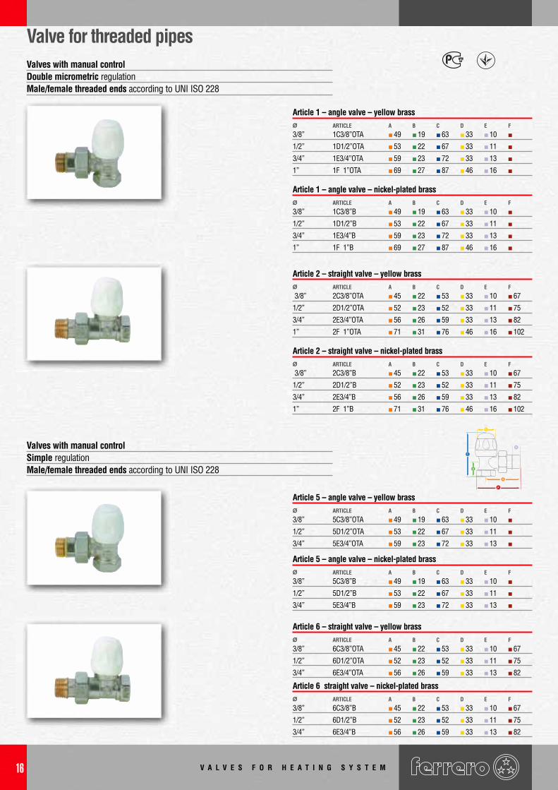
Valve for threaded pipes
3/8” 1C3/8”OTA 49 19 63 33 10
1/2” 1D1/2”OTA 53 22 67 33 11
3/4” 1E3/4”OTA 59 23 72 33 13
1” 1F 1”OTA 69 27 87 46 16
Ø ARTICLE CBA D E F
Article 1 – angle valve – yellow brass
3/8” 1C3/8”B 49 19 63 33 10
1/2” 1D1/2”B 53 22 67 33 11
3/4” 1E3/4”B 59 23 72 33 13
1” 1F 1”B 69 27 87 46 16
Ø ARTICLE CBA D E F
Article 1 – angle valve – nickel-plated brass
3/8” 2C3/8”OTA 45 22 53 33 10 67
1/2” 2D1/2”OTA 52 23 52 33 11 75
3/4” 2E3/4”OTA 56 26 59 33 13 82
1” 2F 1”OTA 71 31 76 46 16 102
Ø ARTICLE CBA D E F
Article 2 – straight valve – yellow brass
3/8” 2C3/8”B 45 22 53 33 10 67
1/2” 2D1/2”B 52 23 52 33 11 75
3/4” 2E3/4”B 56 26 59 33 13 82
1” 2F 1”B 71 31 76 46 16 102
Ø ARTICLE CBA D E F
Article 2 – straight valve – nickel-plated brass
3/8” 5C3/8”OTA 49 19 63 33 10
1/2” 5D1/2”OTA 53 22 67 33 11
3/4” 5E3/4”OTA 59 23 72 33 13
Ø ARTICLE CBA D E F
Article 5 – angle valve – yellow brass
3/8” 5C3/8”B 49 19 63 33 10
1/2” 5D1/2”B 53 22 67 33 11
3/4” 5E3/4”B 59 23 72 33 13
Ø ARTICLE CBA D E F
Article 5 – angle valve – nickel-plated brass
3/8” 6C3/8”OTA 45 22 53 33 10 67
1/2” 6D1/2”OTA 52 23 52 33 11 75
3/4” 6E3/4”OTA 56 26 59 33 13 82
Ø ARTICLE CBA D E F
Article 6 – straight valve – yellow brass
3/8” 6C3/8”B 45 22 53 33 10 67
1/2” 6D1/2”B 52 23 52 33 11 75
3/4” 6E3/4”B 56 26 59 33 13 82
Ø ARTICLE CBA D E F
Article 6 straight valve – nickel-plated brass
Valves with manual controlDouble micrometric regulationMale/female threaded ends according to UNI ISO 228
Valves with manual controlSimple regulationMale/female threaded ends according to UNI ISO 228
C
E
F
V A L V E S F O R H E A T I N G S Y S T E M 17
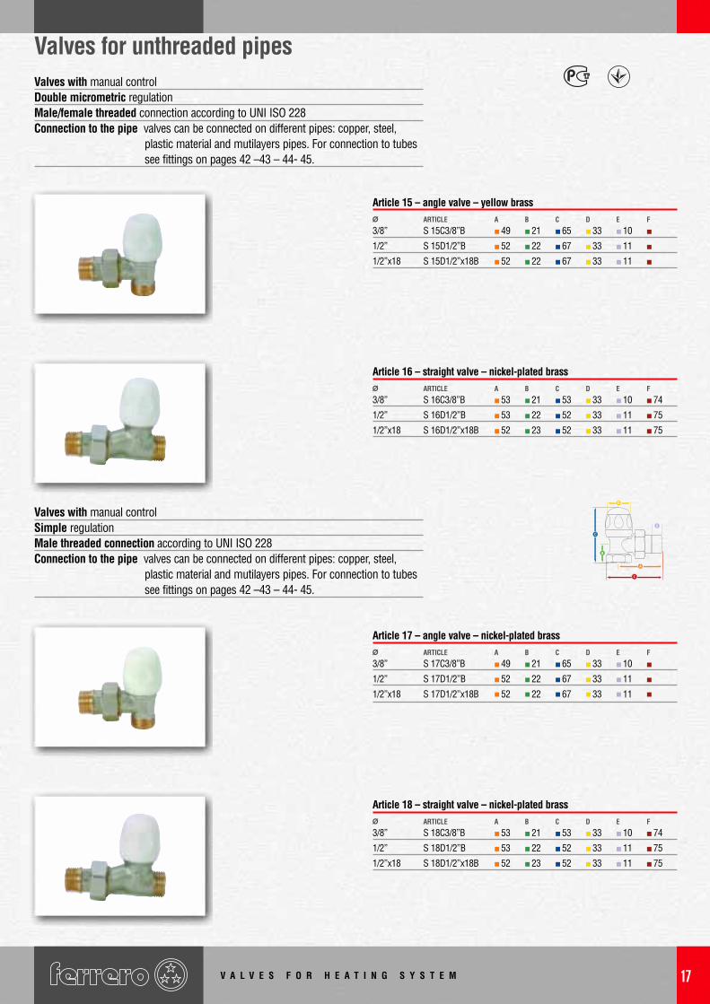
Valves for unthreaded pipes
3/8” S 15C3/8”B 49 21 65 33 10
1/2” S 15D1/2”B 52 22 67 33 11
1/2”x18 S 15D1/2”x18B 52 22 67 33 11
Ø ARTICLE CBA D E F
Article 15 – angle valve – yellow brass
3/8” S 16C3/8”B 53 21 53 33 10 74
1/2” S 16D1/2”B 53 22 52 33 11 75
1/2”x18 S 16D1/2”x18B 52 23 52 33 11 75
Ø ARTICLE CBA D E F
Article 16 – straight valve – nickel-plated brass
3/8” S 17C3/8”B 49 21 65 33 10
1/2” S 17D1/2”B 52 22 67 33 11
1/2”x18 S 17D1/2”x18B 52 22 67 33 11
Ø ARTICLE CBA D E F
Article 17 – angle valve – nickel-plated brass
3/8” S 18C3/8”B 53 21 53 33 10 74
1/2” S 18D1/2”B 53 22 52 33 11 75
1/2”x18 S 18D1/2”x18B 52 23 52 33 11 75
Ø ARTICLE CBA D E F
Article 18 – straight valve – nickel-plated brass
Valves with manual controlDouble micrometric regulationMale/female threaded connection according to UNI ISO 228Connection to the pipe valves can be connected on different pipes: copper, steel,
plastic material and mutilayers pipes. For connection to tubes see fittings on pages 42 –43 – 44- 45.
Valves with manual controlSimple regulationMale threaded connection according to UNI ISO 228Connection to the pipe valves can be connected on different pipes: copper, steel,
plastic material and mutilayers pipes. For connection to tubes see fittings on pages 42 –43 – 44- 45.
C
E
F
V A L V E S F O R H E A T I N G S Y S T E M18
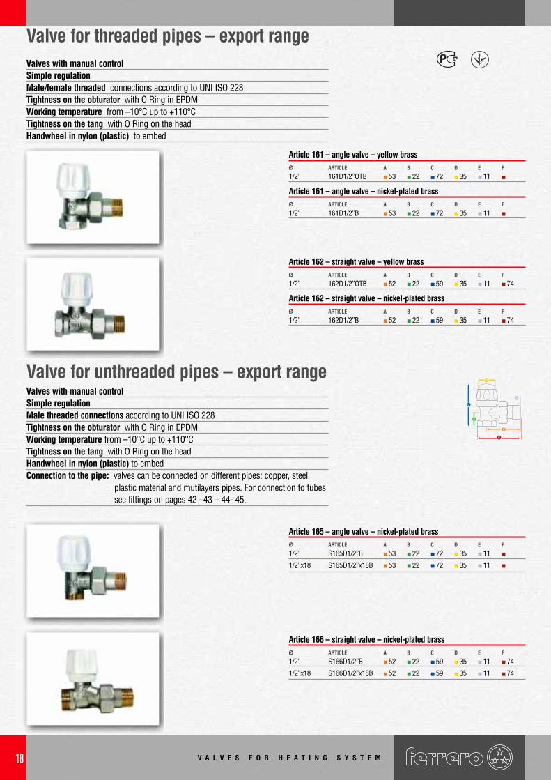
Valves with manual controlSimple regulationMale/female threaded connections according to UNI ISO 228Tightness on the obturator with O Ring in EPDMWorking temperature from –10°C up to +110°CTightness on the tang with O Ring on the headHandwheel in nylon (plastic) to embed
Valve for threaded pipes – export range
1/2” 161D1/2”OTB 53 22 72 35 11Ø ARTICLE CBA D E F
Article 161 – angle valve – yellow brass
1/2” 161D1/2”B 53 22 72 35 11Ø ARTICLE CBA D E F
Article 161 – angle valve – nickel-plated brass
1/2” 162D1/2”OTB 52 22 59 35 11 74Ø ARTICLE CBA D E F
Article 162 – straight valve – yellow brass
1/2” 162D1/2”B 52 22 59 35 11 74Ø ARTICLE CBA D E F
Article 162 – straight valve – nickel-plated brass
1/2” S165D1/2”B 53 22 72 35 11
1/2”x18 S165D1/2”x18B 53 22 72 35 11
Ø ARTICLE CBA D E F
Article 165 – angle valve – nickel-plated brass
1/2” S166D1/2”B 52 22 59 35 11 74
1/2”x18 S166D1/2”x18B 52 22 59 35 11 74
Ø ARTICLE CBA D E F
Article 166 – straight valve – nickel-plated brass
Valve for unthreaded pipes – export rangeValves with manual controlSimple regulationMale threaded connections according to UNI ISO 228Tightness on the obturator with O Ring in EPDMWorking temperature from –10°C up to +110°CTightness on the tang with O Ring on the headHandwheel in nylon (plastic) to embedConnection to the pipe: valves can be connected on different pipes: copper, steel,
plastic material and mutilayers pipes. For connection to tubes see fittings on pages 42 –43 – 44- 45.
C
E
F
V A L V E S F O R H E A T I N G S Y S T E M 19
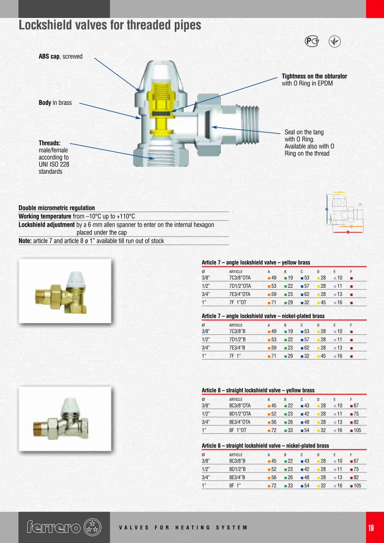
Lockshield valves for threaded pipes
3/8” 7C3/8”OTA 49 19 53 28 10
1/2” 7D1/2”OTA 53 22 57 28 11
3/4” 7E3/4”OTA 59 23 62 28 13
1” 7F 1”OT 71 29 32 45 16
Ø ARTICLE CBA D E F
Article 7 – angle lockshield valve – yellow brass
3/8” 7C3/8”B 49 19 53 28 10
1/2” 7D1/2”B 53 22 57 28 11
3/4” 7E3/4”B 59 23 62 28 13
1” 7F 1” 71 29 32 45 16
Ø ARTICLE CBA D E F
Article 7 – angle lockshield valve – nickel-plated brass
3/8” 8C3/8”OTA 45 22 43 28 10 67
1/2” 8D1/2”OTA 52 23 42 28 11 75
3/4” 8E3/4”OTA 56 26 48 28 13 82
1” 8F 1”OT 72 33 54 32 16 105
Ø ARTICLE CBA D E F
Article 8 – straight lockshield valve – yellow brass
3/8” 8C3/8”B 45 22 43 28 10 67
1/2” 8D1/2”B 52 23 42 28 11 75
3/4” 8E3/4”B 56 26 48 28 13 82
1” 8F 1” 72 33 54 32 16 105
Ø ARTICLE CBA D E F
Article 8 – straight lockshield valve – nickel-plated brass
Double micrometric regulationWorking temperature from –10°C up to +110°CLockshield adjustment by a 6 mm allen spanner to enter on the internal hexagon
placed under the capNote: article 7 and article 8 ø 1” available till run out of stock
ABS cap, screwed
Tightness on the obturatorwith O Ring in EPDM
Seal on the tang with O Ring.Available also with ORing on the thread
Threads:male/femaleaccording to UNI ISO 228standards
Body in brass
C
E
F
V A L V E S F O R H E A T I N G S Y S T E M20
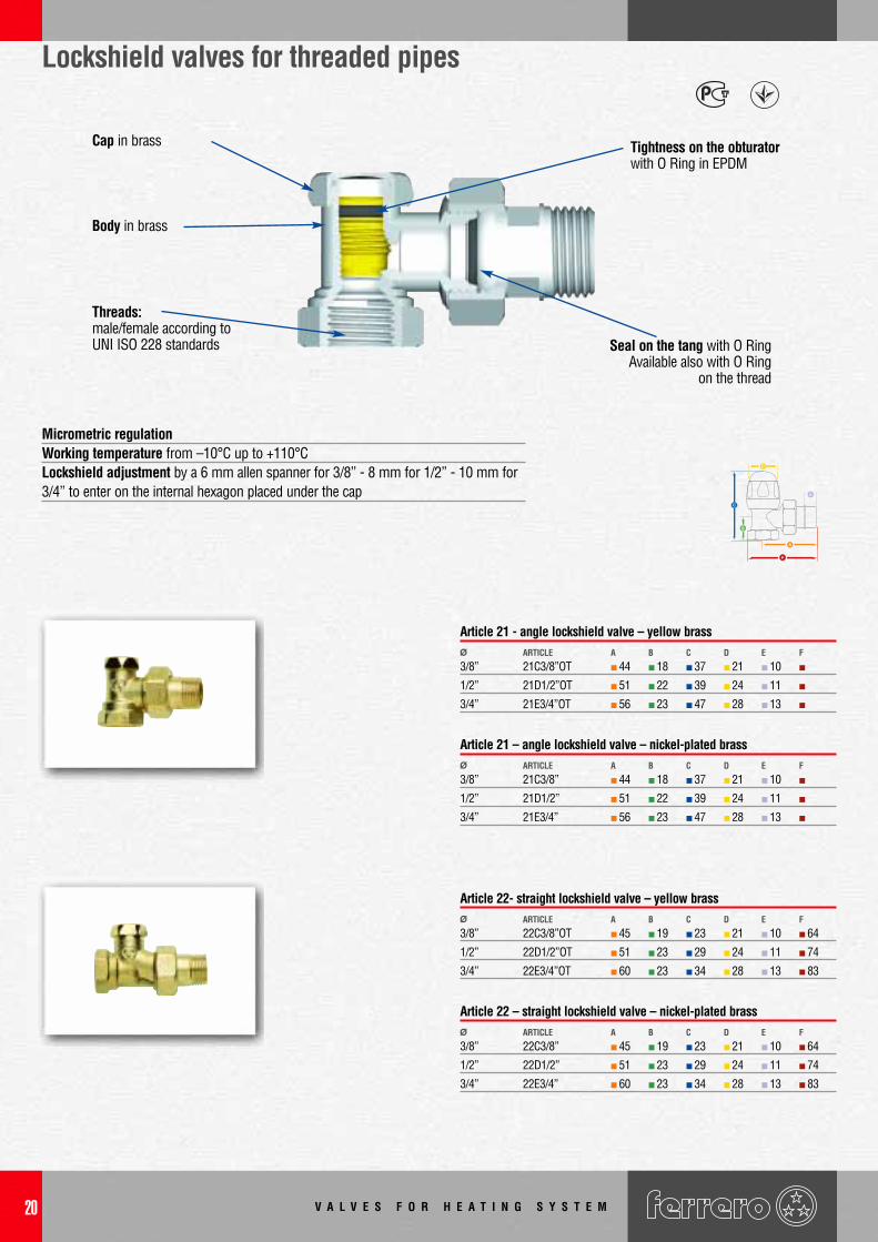
Lockshield valves for threaded pipes
3/8” 22C3/8”OT 45 19 23 21 10 64
1/2” 22D1/2”OT 51 23 29 24 11 74
3/4” 22E3/4”OT 60 23 34 28 13 83
Ø ARTICLE CBA D E F
Article 22- straight lockshield valve – yellow brass
3/8” 22C3/8” 45 19 23 21 10 64
1/2” 22D1/2” 51 23 29 24 11 74
3/4” 22E3/4” 60 23 34 28 13 83
Ø ARTICLE CBA D E F
Article 22 – straight lockshield valve – nickel-plated brass
Micrometric regulationWorking temperature from –10°C up to +110°CLockshield adjustment by a 6 mm allen spanner for 3/8” - 8 mm for 1/2” - 10 mm for3/4” to enter on the internal hexagon placed under the cap
3/8” 21C3/8”OT 44 18 37 21 10
1/2” 21D1/2”OT 51 22 39 24 11
3/4” 21E3/4”OT 56 23 47 28 13
Ø ARTICLE CBA D E F
Article 21 - angle lockshield valve – yellow brass
3/8” 21C3/8” 44 18 37 21 10
1/2” 21D1/2” 51 22 39 24 11
3/4” 21E3/4” 56 23 47 28 13
Ø ARTICLE CBA D E F
Article 21 – angle lockshield valve – nickel-plated brass
Cap in brass Tightness on the obturatorwith O Ring in EPDM
Seal on the tang with O RingAvailable also with O Ring
on the thread
Body in brass
Threads:male/female according toUNI ISO 228 standards
C
E
F
V A L V E S F O R H E A T I N G S Y S T E M 21
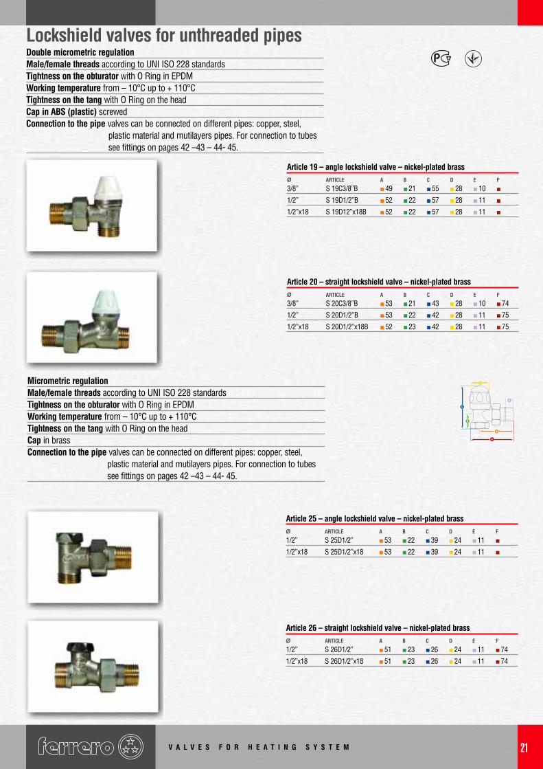
3/8” S 19C3/8”B 49 21 55 28 10
1/2” S 19D1/2”B 52 22 57 28 11
1/2”x18 S 19D12”x18B 52 22 57 28 11
Ø ARTICLE CBA D E F
Article 19 – angle lockshield valve – nickel-plated brass
3/8” S 20C3/8”B 53 21 43 28 10 74
1/2” S 20D1/2”B 53 22 42 28 11 75
1/2”x18 S 20D1/2”x18B 52 23 42 28 11 75
Ø ARTICLE CBA D E F
Article 20 – straight lockshield valve – nickel-plated brass
Lockshield valves for unthreaded pipesDouble micrometric regulationMale/female threads according to UNI ISO 228 standardsTightness on the obturator with O Ring in EPDMWorking temperature from – 10°C up to + 110°CTightness on the tang with O Ring on the headCap in ABS (plastic) screwedConnection to the pipe valves can be connected on different pipes: copper, steel,
plastic material and mutilayers pipes. For connection to tubes see fittings on pages 42 –43 – 44- 45.
1/2” S 25D1/2” 53 22 39 24 11
1/2”x18 S 25D1/2”x18 53 22 39 24 11
Ø ARTICLE CBA D E F
Article 25 – angle lockshield valve – nickel-plated brass
1/2” S 26D1/2” 51 23 26 24 11 74
1/2”x18 S 26D1/2”x18 51 23 26 24 11 74
Ø ARTICLE CBA D E F
Article 26 – straight lockshield valve – nickel-plated brass
Micrometric regulationMale/female threads according to UNI ISO 228 standardsTightness on the obturator with O Ring in EPDMWorking temperature from – 10°C up to + 110°CTightness on the tang with O Ring on the headCap in brassConnection to the pipe valves can be connected on different pipes: copper, steel,
plastic material and mutilayers pipes. For connection to tubes see fittings on pages 42 –43 – 44- 45.
C
E
F
V A L V E S F O R H E A T I N G S Y S T E M22
Once the lockshield has been calibrated the double regulator can be fixed in the settingposition so that the lockshield valve can be closed completely but only opens as far asthe calibration position.As not all the lockshield valve need calibration ad usually do not need to be closed,Ferrero designed a simple item that screwed onto the head of our items no. 21-22-25-26, transforms them into a double regulation lockshields.
Function The “double regulator” is composed of two pieces, the extension A andinternal ring nut B. To install, take off the lockschield cap C and screw on the extensionA. Screw the ring nut B with an hexagonal allen key till it touches the shutter fixing theposition. Close the lockshield without moving the screw nut B. Re-place the cap C ontoA. The shutter can be fully closed and opened to the calibrated position where it isblocked by the screw nut B.
Double regulation for lockshield valves (patented)
3/8” 474C3/8”OT 8
1/2” 474D1/2”OT 10
FOR VALVES Ø ARTICLE KEY Ø
Article 474 – yellow brass
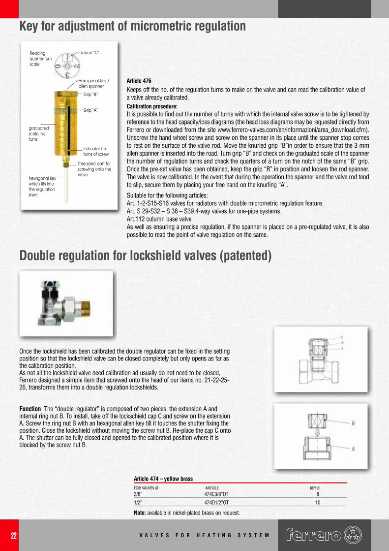
Article 476Keeps off the no. of the regulation turns to make on the valve and can read the calibration value ofa valve already calibrated.Calibration procedure:It is possible to find out the number of turns with which the internal valve screw is to be tightened byreference to the head capacity/loss diagrams (the head loss diagrams may be requested directly fromFerrero or downloaded from the site www.ferrero-valves.com/en/informazioni/area_download.cfm).Unscrew the hand wheel screw and screw on the spanner in its place until the spanner stop comesto rest on the surface of the valve rod. Move the knurled grip “B”in order to ensure that the 3 mmallen spanner is inserted into the road. Turn grip “B” and check on the graduated scale of the spannerthe number of regulation turns and check the quarters of a turn on the notch of the same “B” grip.Once the pre-set value has been obtained, keep the grip “B” in position and loosen the rod spanner.The valve is now calibrated. In the event that during the operation the spanner and the valve rod tendto slip, secure them by placing your free hand on the knurling “A”.
Suitable for the following articles:Art. 1-2-S15-S16 valves for radiators with double micrometric regulation feature.Art. S 29-S32 – S 38 – S39 4-way valves for one-pipe systems.Art.112 column base valveAs well as ensuring a precise regulation, if the spanner is placed on a pre-regulated valve, it is alsopossible to read the point of valve regulation on the same.
Hexagonal key /allen spanner
Grip “B”
Grip “A”
graduatedscale, no.turns
indicator no.turns of screw
Incision “C”.Reading quarter-turn scale
Threaded part forscrewing onto thevalve
hexagonal keywhich fits intothe regulationstem
Key for adjustment of micrometric regulation
Note: available in nickel-plated brass on request.
V A L V E S F O R H E A T I N G S Y S T E M 23
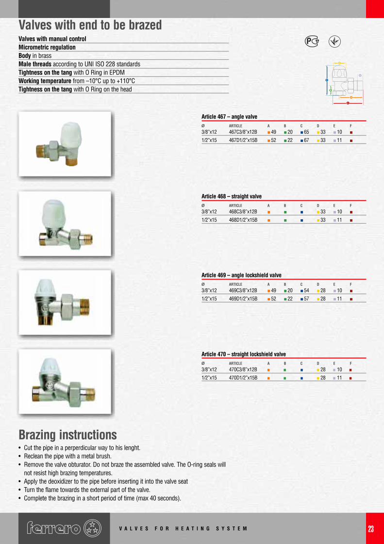
Valves with end to be brazedValves with manual controlMicrometric regulationBody in brassMale threads according to UNI ISO 228 standardsTightness on the tang with O Ring in EPDMWorking temperature from –10°C up to +110°CTightness on the tang with O Ring on the head
3/8”x12 467C3/8”x12B 49 20 65 33 10
1/2”x15 467D1/2”x15B 52 22 67 33 11
Ø ARTICLE CBA D E F
Article 467 – angle valve
3/8”x12 468C3/8”x12B 33 10
1/2”x15 468D1/2”x15B 33 11
Ø ARTICLE CBA D E F
Article 468 – straight valve
3/8”x12 469C3/8”x12B 49 20 54 28 10
1/2”x15 469D1/2”x15B 52 22 57 28 11
Ø ARTICLE CBA D E F
Article 469 – angle lockshield valve
3/8”x12 470C3/8”x12B 28 10
1/2”x15 470D1/2”x15B 28 11
Ø ARTICLE CBA D E F
Article 470 – straight lockshield valve
Brazing instructions• Cut the pipe in a perperdicular way to his lenght.• Reclean the pipe with a metal brush.• Remove the valve obturator. Do not braze the assembled valve. The O-ring seals will
not resist high brazing temperatures.• Apply the deoxidizer to the pipe before inserting it into the valve seat • Turn the flame towards the external part of the valve.• Complete the brazing in a short period of time (max 40 seconds).
C
E
F
V A L V E S F O R H E A T I N G S Y S T E M24
Installation notesFlow direction
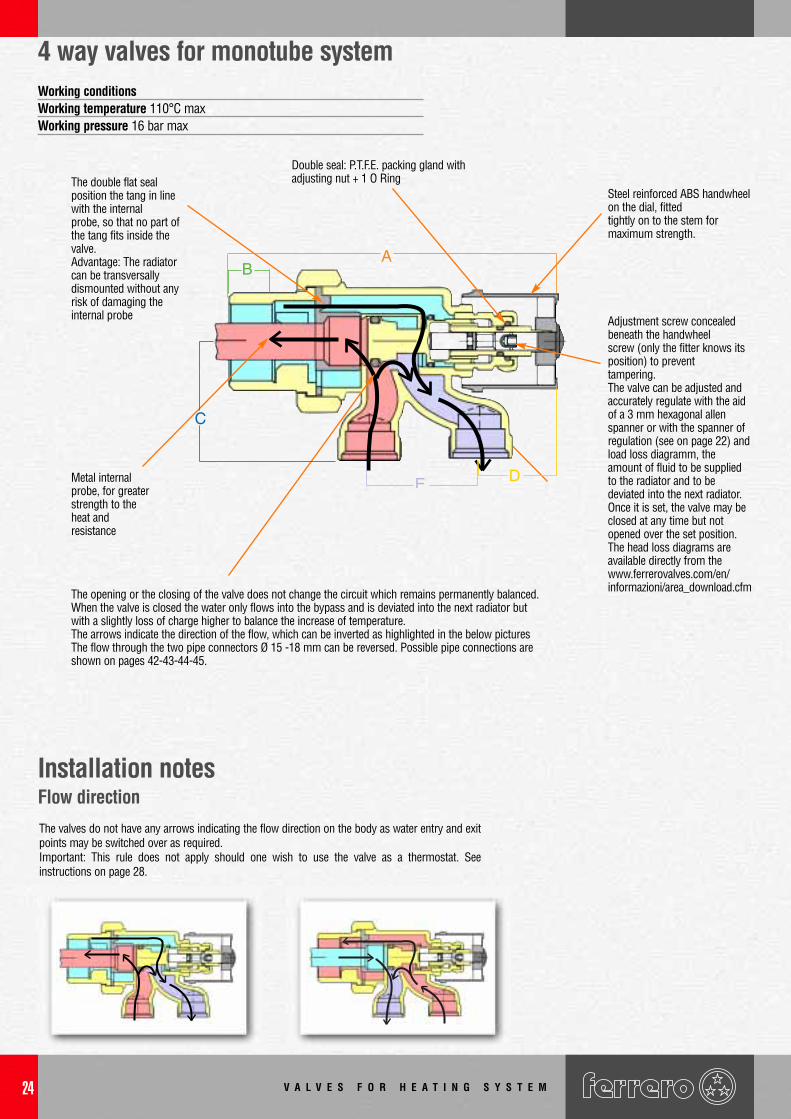
The opening or the closing of the valve does not change the circuit which remains permanently balanced.When the valve is closed the water only flows into the bypass and is deviated into the next radiator butwith a slightly loss of charge higher to balance the increase of temperature.The arrows indicate the direction of the flow, which can be inverted as highlighted in the below picturesThe flow through the two pipe connectors Ø 15 -18 mm can be reversed. Possible pipe connections areshown on pages 42-43-44-45.
Metal internalprobe, for greaterstrength to theheat andresistance
The double flat sealposition the tang in linewith the internalprobe, so that no part ofthe tang fits inside thevalve.Advantage: The radiatorcan be transversallydismounted without anyrisk of damaging theinternal probe
Double seal: P.T.F.E. packing gland withadjusting nut + 1 O Ring
Steel reinforced ABS handwheelon the dial, fittedtightly on to the stem formaximum strength.
Adjustment screw concealedbeneath the handwheelscrew (only the fitter knows itsposition) to preventtampering.The valve can be adjusted andaccurately regulate with the aidof a 3 mm hexagonal allenspanner or with the spanner ofregulation (see on page 22) andload loss diagramm, theamount of fluid to be suppliedto the radiator and to bedeviated into the next radiator. Once it is set, the valve may beclosed at any time but not opened over the set position.The head loss diagrams areavailable directly from the www.ferrerovalves.com/en/informazioni/area_download.cfm
Working conditions Working temperature 110°C maxWorking pressure 16 bar max
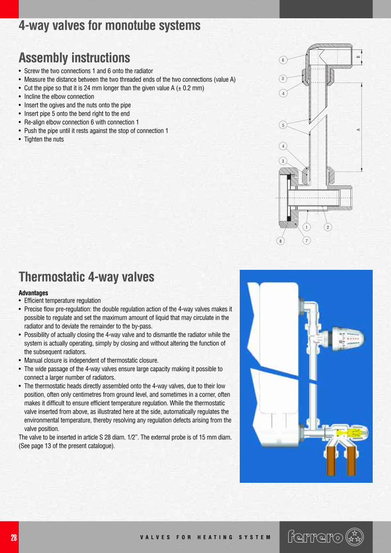
4 way valves for monotube system
The valves do not have any arrows indicating the flow direction on the body as water entry and exitpoints may be switched over as required.Important: This rule does not apply should one wish to use the valve as a thermostat. Seeinstructions on page 28.
V A L V E S F O R H E A T I N G S Y S T E M 25
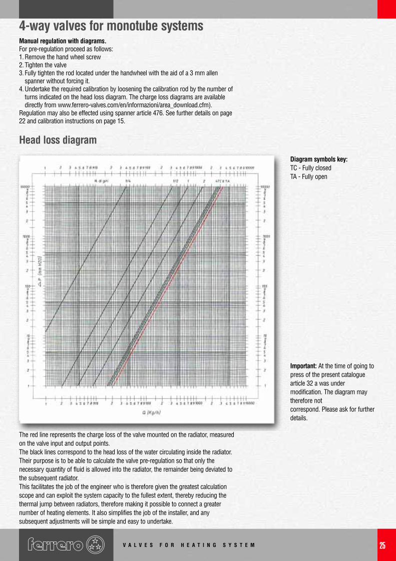
4-way valves for monotube systemsManual regulation with diagrams.For pre-regulation proceed as follows:1. Remove the hand wheel screw2. Tighten the valve3. Fully tighten the rod located under the handwheel with the aid of a 3 mm allen
spanner without forcing it.4. Undertake the required calibration by loosening the calibration rod by the number of
turns indicated on the head loss diagram. The charge loss diagrams are availabledirectly from www.ferrero-valves.com/en/informazioni/area_download.cfm).
Regulation may also be effected using spanner article 476. See further details on page22 and calibration instructions on page 15.
Diagram symbols key:TC - Fully closedTA - Fully open
Important: At the time of going topress of the present cataloguearticle 32 a was undermodification. The diagram maytherefore notcorrespond. Please ask for furtherdetails.
Head loss diagram
The red line represents the charge loss of the valve mounted on the radiator, measuredon the valve input and output points.The black lines correspond to the head loss of the water circulating inside the radiator.Their purpose is to be able to calculate the valve pre-regulation so that only thenecessary quantity of fluid is allowed into the radiator, the remainder being deviated tothe subsequent radiator.This facilitates the job of the engineer who is therefore given the greatest calculationscope and can exploit the system capacity to the fullest extent, thereby reducing thethermal jump between radiators, therefore making it possible to connect a greaternumber of heating elements. It also simplifies the job of the installer, and anysubsequent adjustments will be simple and easy to undertake.
V A L V E S F O R H E A T I N G S Y S T E M26
4 way valves for monotube system
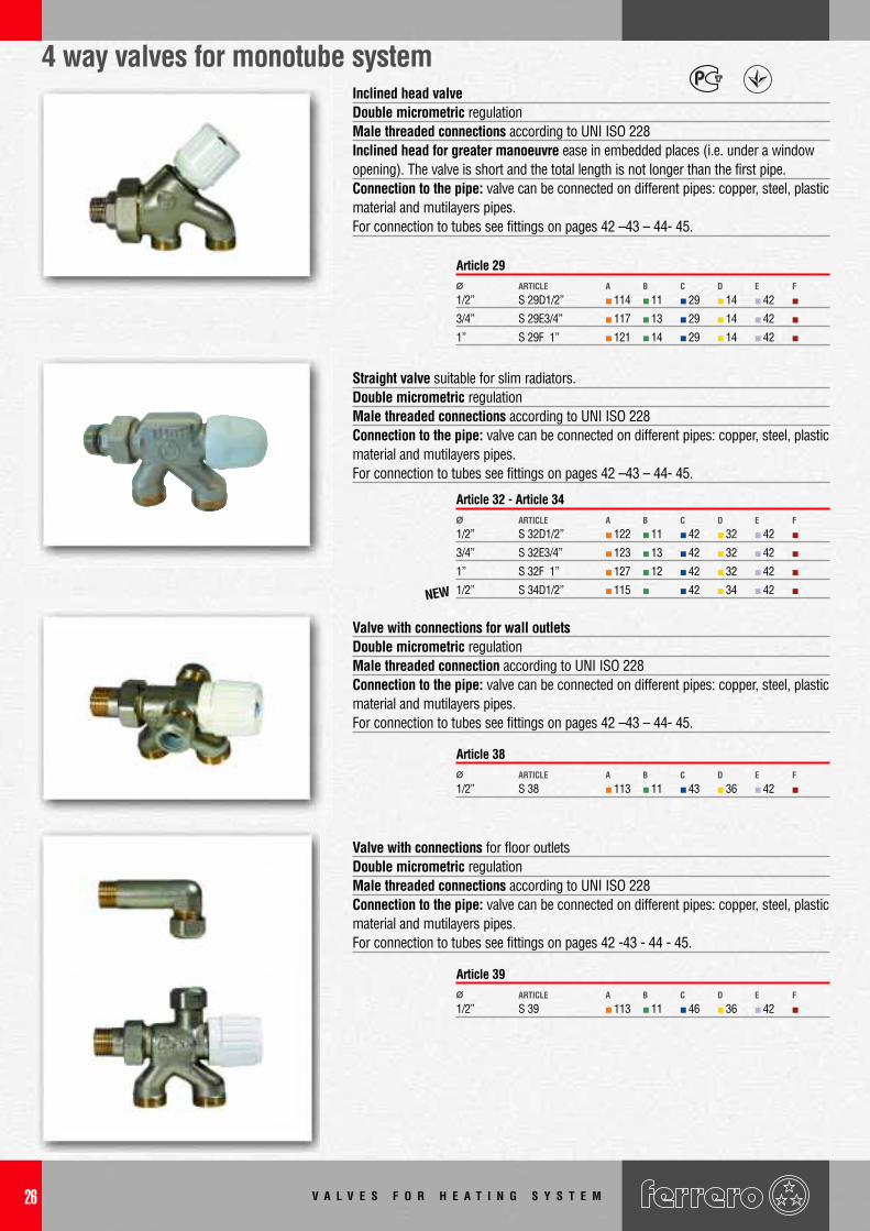
1/2” S 29D1/2” 114 11 29 14 42
3/4” S 29E3/4” 117 13 29 14 42
1” S 29F 1” 121 14 29 14 42
Ø ARTICLE CBA D E F
Article 29
1/2” S 32D1/2” 122 11 42 32 42
3/4” S 32E3/4” 123 13 42 32 42
1” S 32F 1” 127 12 42 32 42
1/2” S 34D1/2” 115 42 34 42
Ø ARTICLE CBA D E F
Article 32 - Article 34
1/2” S 38 113 11 43 36 42Ø ARTICLE CBA D E F
Article 38
Straight valve suitable for slim radiators.Double micrometric regulationMale threaded connections according to UNI ISO 228Connection to the pipe: valve can be connected on different pipes: copper, steel, plasticmaterial and mutilayers pipes. For connection to tubes see fittings on pages 42 –43 – 44- 45.
Valve with connections for wall outletsDouble micrometric regulationMale threaded connection according to UNI ISO 228Connection to the pipe: valve can be connected on different pipes: copper, steel, plasticmaterial and mutilayers pipes. For connection to tubes see fittings on pages 42 –43 – 44- 45.
1/2” S 39 113 11 46 36 42Ø ARTICLE CBA D E F
Article 39
Valve with connections for floor outletsDouble micrometric regulationMale threaded connections according to UNI ISO 228Connection to the pipe: valve can be connected on different pipes: copper, steel, plasticmaterial and mutilayers pipes. For connection to tubes see fittings on pages 42 -43 - 44 - 45.
Inclined head valveDouble micrometric regulationMale threaded connections according to UNI ISO 228Inclined head for greater manoeuvre ease in embedded places (i.e. under a window opening). The valve is short and the total length is not longer than the first pipe.Connection to the pipe: valve can be connected on different pipes: copper, steel, plasticmaterial and mutilayers pipes. For connection to tubes see fittings on pages 42 –43 – 44- 45.
NEW
V A L V E S F O R H E A T I N G S Y S T E M 27
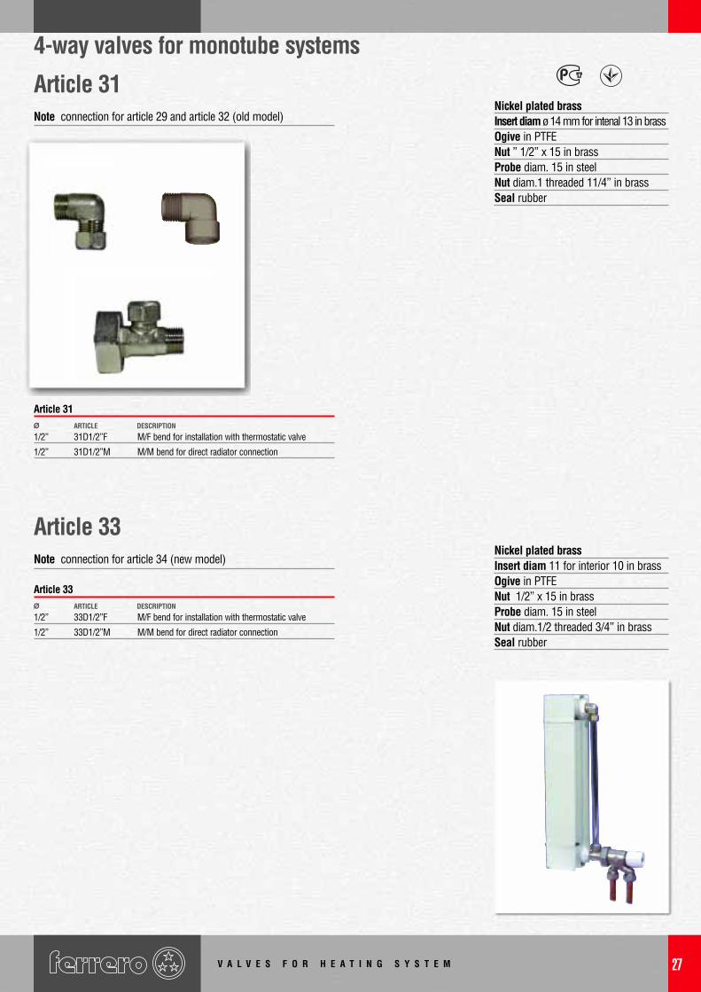
4-way valves for monotube systems
Nickel plated brassInsert diam ø 14 mm for intenal 13 in brassOgive in PTFENut ” 1/2” x 15 in brassProbe diam. 15 in steelNut diam.1 threaded 11/4” in brassSeal rubber
Nickel plated brassInsert diam 11 for interior 10 in brassOgive in PTFENut 1/2” x 15 in brassProbe diam. 15 in steelNut diam.1/2 threaded 3/4” in brassSeal rubber
Article 33Note connection for article 34 (new model)
Article 31 Note connection for article 29 and article 32 (old model)
1/2” 31D1/2”F M/F bend for installation with thermostatic valve
1/2” 31D1/2”M M/M bend for direct radiator connection
Ø ARTICLE DESCRIPTION
Article 31
1/2” 33D1/2”F M/F bend for installation with thermostatic valve
1/2” 33D1/2”M M/M bend for direct radiator connection
Ø ARTICLE DESCRIPTION
Article 33
V A L V E S F O R H E A T I N G S Y S T E M28
4-way valves for monotube systems
Assembly instructions• Screw the two connections 1 and 6 onto the radiator• Measure the distance between the two threaded ends of the two connections (value A)• Cut the pipe so that it is 24 mm longer than the given value A (± 0.2 mm)• Incline the elbow connection• Insert the ogives and the nuts onto the pipe• Insert pipe 5 onto the bend right to the end• Re-align elbow connection 6 with connection 1• Push the pipe until it rests against the stop of connection 1• Tighten the nuts
6
3
4
5
4
3
8 7
1 2
BA
Thermostatic 4-way valvesAdvantages• Efficient temperature regulation• Precise flow pre-regulation: the double regulation action of the 4-way valves makes it
possible to regulate and set the maximum amount of liquid that may circulate in theradiator and to deviate the remainder to the by-pass.
• Possibility of actually closing the 4-way valve and to dismantle the radiator while thesystem is actually operating, simply by closing and without altering the function ofthe subsequent radiators.
• Manual closure is independent of thermostatic closure.• The wide passage of the 4-way valves ensure large capacity making it possible to
connect a larger number of radiators.• The thermostatic heads directly assembled onto the 4-way valves, due to their low
position, often only centimetres from ground level, and sometimes in a corner, oftenmakes it difficult to ensure efficient temperature regulation. While the thermostaticvalve inserted from above, as illustrated here at the side, automatically regulates theenvironmental temperature, thereby resolving any regulation defects arising from thevalve position.
The valve to be inserted in article S 28 diam. 1/2”. The external probe is of 15 mm diam.(See page 13 of the present catalogue).
V A L V E S F O R H E A T I N G S Y S T E M 29
Accessories for 4 way valve
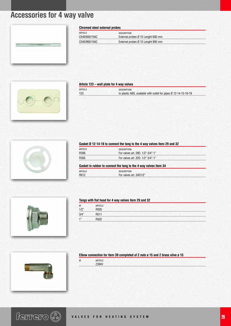
C540/600/15AC External probes Ø 15 Lenght 600 mm
C540/900/15AC External probes Ø 15 Lenght 900 mm
ARTICLE DESCRIPTION
Chromed steel external probes
123 In plastic ABS, available with outlet for pipes Ø 12-14-15-16-18ARTICLE DESCRIPTION
Article 123 – wall plate for 4 way valves
R306 For valves art. 29D. 1/2”-3/4”-1”
R305 For valves art. 32D. 1/2”-3/4”-1”
ARTICLE
ARTICLE
DESCRIPTION
Gasket Ø 12-14-18 to connect the tang to the 4 way valves item 29 and 32
1/2” R505
3/4” R511
1” R502
Ø ARTICLE
Tangs with flat head for 4 way valves item 29 and 32
Z394VØ ARTICLE
Elbow connection for item 39 completed of 2 nuts ø 15 and 2 brass olive ø 15
R612 For valves art. 34D1/2”DESCRIPTION
Gasket in rubber to connect the tang to the 4 way valves item 34
V A L V E S F O R H E A T I N G S Y S T E M30
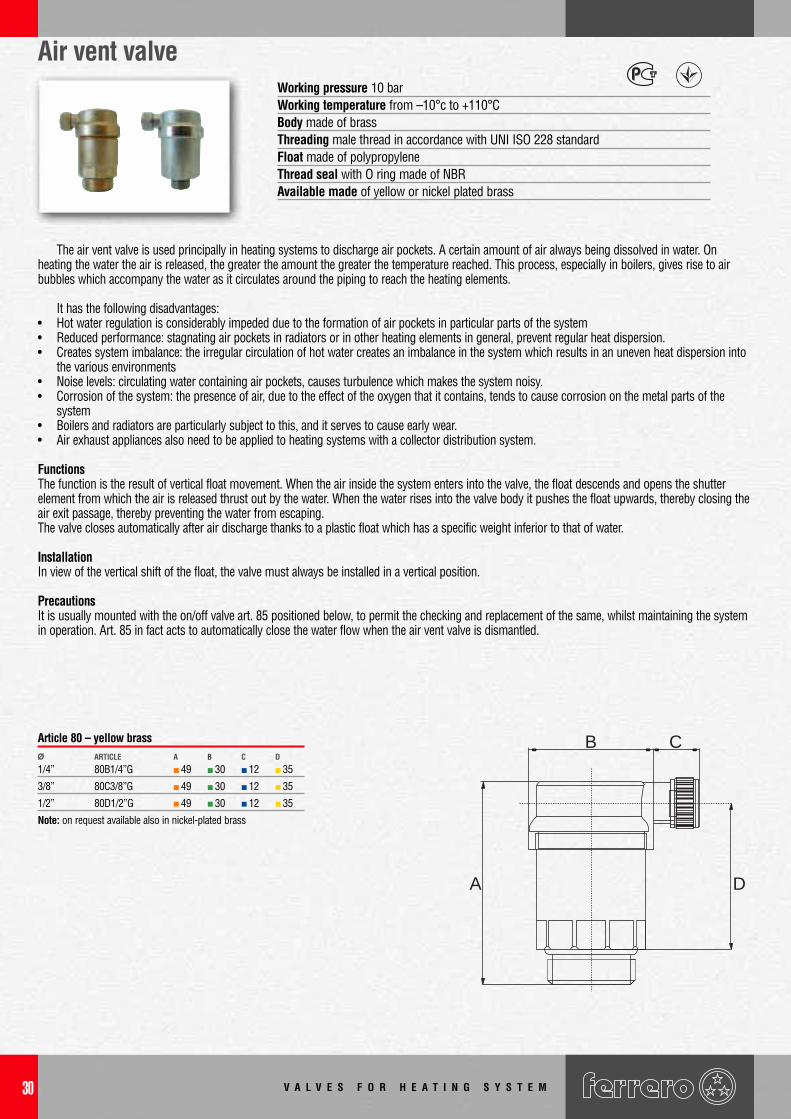
Air vent valve
The air vent valve is used principally in heating systems to discharge air pockets. A certain amount of air always being dissolved in water. Onheating the water the air is released, the greater the amount the greater the temperature reached. This process, especially in boilers, gives rise to airbubbles which accompany the water as it circulates around the piping to reach the heating elements.
It has the following disadvantages:• Hot water regulation is considerably impeded due to the formation of air pockets in particular parts of the system• Reduced performance: stagnating air pockets in radiators or in other heating elements in general, prevent regular heat dispersion.• Creates system imbalance: the irregular circulation of hot water creates an imbalance in the system which results in an uneven heat dispersion into
the various environments• Noise levels: circulating water containing air pockets, causes turbulence which makes the system noisy.• Corrosion of the system: the presence of air, due to the effect of the oxygen that it contains, tends to cause corrosion on the metal parts of the
system• Boilers and radiators are particularly subject to this, and it serves to cause early wear.• Air exhaust appliances also need to be applied to heating systems with a collector distribution system.
FunctionsThe function is the result of vertical float movement. When the air inside the system enters into the valve, the float descends and opens the shutterelement from which the air is released thrust out by the water. When the water rises into the valve body it pushes the float upwards, thereby closing theair exit passage, thereby preventing the water from escaping.The valve closes automatically after air discharge thanks to a plastic float which has a specific weight inferior to that of water.
InstallationIn view of the vertical shift of the float, the valve must always be installed in a vertical position.
PrecautionsIt is usually mounted with the on/off valve art. 85 positioned below, to permit the checking and replacement of the same, whilst maintaining the systemin operation. Art. 85 in fact acts to automatically close the water flow when the air vent valve is dismantled.
A
B C
D
Working pressure 10 barWorking temperature from –10°c to +110°CBody made of brassThreading male thread in accordance with UNI ISO 228 standardFloat made of polypropyleneThread seal with O ring made of NBRAvailable made of yellow or nickel plated brass
1/4” 80B1/4”G 49 30 12 35
3/8” 80C3/8”G 49 30 12 35
1/2” 80D1/2”G 49 30 12 35
Note: on request available also in nickel-plated brass
Ø ARTICLE CBA D
Article 80 – yellow brass
V A L V E S F O R H E A T I N G S Y S T E M 31
Air vent valve with manual control
Hand wheel and shutter made of HostaformWorking pressure max. 10 barWorking temperature max. 110°CVersions with PTFE ring on threadWithout ring on thread
Body made of brass. Nickel plated version available on requestSealing O-RING in NBRShut of element made of polyethyleneWorking pressure max 10 barWorking pressure max. 110°C
Automatic shut off adaptor valve
A
B
It is usually mounted below theautomatic air vent valve, so as topermit the checking or thereplacement of art. 80 whilstmaintaining the system in operation.Article 85 in fact automatically shutsoff the water flow on the dismantlingof the air vent valve.
1/4” 81B1/4”TFB 26 18 13
3/8” 81C3/8”TFB 26 18 17
1/2” 81D1/2”TFB 26 18 21
Ø ARTICLE CBA
Article 81- With PTFE ring on thread
1/8” 81A1/8”B 24 18 11
1/4” 81B1/4”B 25 18 13
3/8” 81C3/8”B 25 18 17
1/2” 81D1/2”B 25 18 21
Ø ARTICLE CBA
Article 81- Without ring on thread
3/8” 85C3/8”OT 19 25
1/2” 85D1/2”OT 23 25
Ø ARTICLE CBA
Article 85 – yellow brass
V A L V E S F O R H E A T I N G S Y S T E M32
3/4”x1/2”M 35E3/4”x1/2GM 89 42 24 23 26
1”x1/2”M 35F 1”x1/2GM 100 42 30 28 33
1”x24M 35F 1”xT18GM 100 42 30 28 33
1”x1/2”F 35F 1”x1/2GF 100 42 30 28 33
11/4”x1/2”M 35G11/4”x1/2GM 108 42 33 33 41
11/4”x24M 35G11/4”xT18GM 108 42 33 33 41
11/4”x1/2”F 35G11/4”x1/2GF 108 42 33 33 41
Ø ARTICLE CBA D E F
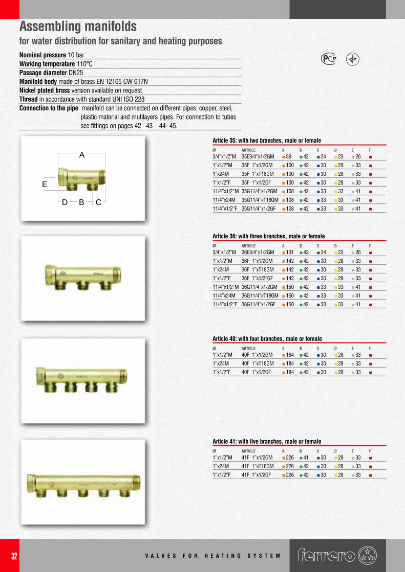
Article 35: with two branches, male or female
3/4”x1/2”M 36E3/4”x1/2GM 131 42 24 23 26
1”x1/2”M 36F 1”x1/2GM 142 42 30 28 33
1”x24M 36F 1”xT18GM 142 42 30 28 33
1”x1/2”F 36F 1”x1/2”GF 142 42 30 28 33
11/4”x1/2”M 36G11/4”x1/2GM 150 42 33 33 41
11/4”x24M 36G11/4”xT18GM 150 42 33 33 41
11/4”x1/2”F 36G11/4”x1/2GF 150 42 33 33 41
Ø ARTICLE CBA D E F
Article 36: with three branches, male or female
1”x1/2”M 40F 1”x1/2GM 184 42 30 28 33
1”x24M 40F 1”xT18GM 184 42 30 28 33
1”x1/2”F 40F 1”x1/2GF 184 42 30 28 33
Ø ARTICLE CBA D E F
Article 40: with four branches, male or female
1”x1/2”M 41F 1”x1/2GM 226 41 30 28 33
1”x24M 41F 1”xT18GM 226 42 30 28 33
1”x1/2”F 41F 1”x1/2GF 226 42 30 28 33
Ø ARTICLE CBA D E F
Article 41: with five branches, male or female
Nominal pressure 10 barWorking temperature 110°CPassage diameter DN25Manifold body made of brass EN 12165 CW 617NNickel plated brass version available on requestThread in accordance with standard UNI ISO 228Connection to the pipe manifold can be connected on different pipes: copper, steel,
plastic material and mutilayers pipes. For connection to tubes see fittings on pages 42 –43 – 44- 45.
Assembling manifoldsfor water distribution for sanitary and heating purposes
A
D B C
E
V A L V E S F O R H E A T I N G S Y S T E M 33
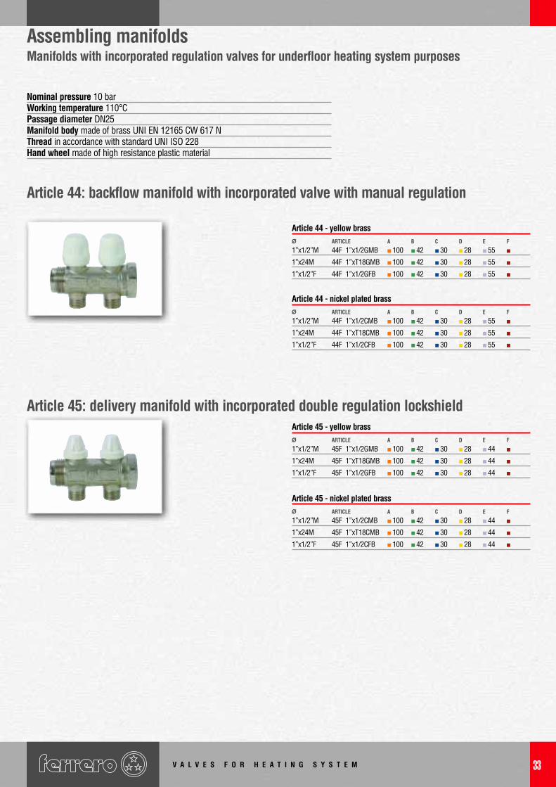
Assembling manifoldsManifolds with incorporated regulation valves for underfloor heating system purposes
1”x1/2”M 44F 1”x1/2GMB 100 42 30 28 55
1”x24M 44F 1”xT18GMB 100 42 30 28 55
1”x1/2”F 44F 1”x1/2GFB 100 42 30 28 55
Ø ARTICLE CBA D E F
Article 44 - yellow brass
1”x1/2”M 44F 1”x1/2CMB 100 42 30 28 55
1”x24M 44F 1”xT18CMB 100 42 30 28 55
1”x1/2”F 44F 1”x1/2CFB 100 42 30 28 55
Ø ARTICLE CBA D E F
Article 44 - nickel plated brass
1”x1/2”M 45F 1”x1/2GMB 100 42 30 28 44
1”x24M 45F 1”xT18GMB 100 42 30 28 44
1”x1/2”F 45F 1”x1/2GFB 100 42 30 28 44
Ø ARTICLE CBA D E F
Article 45 - yellow brass
1”x1/2”M 45F 1”x1/2CMB 100 42 30 28 44
1”x24M 45F 1”xT18CMB 100 42 30 28 44
1”x1/2”F 45F 1”x1/2CFB 100 42 30 28 44
Ø ARTICLE CBA D E F
Article 45 - nickel plated brass
Nominal pressure 10 barWorking temperature 110°CPassage diameter DN25Manifold body made of brass UNI EN 12165 CW 617 NThread in accordance with standard UNI ISO 228Hand wheel made of high resistance plastic material
Article 44: backflow manifold with incorporated valve with manual regulation
Article 45: delivery manifold with incorporated double regulation lockshield
V A L V E S F O R H E A T I N G S Y S T E M34
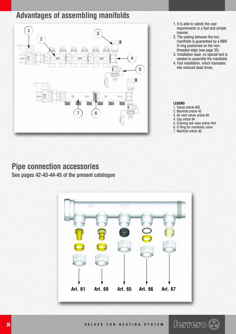
Advantages of assembling manifolds1. It is able to satisfy the user
requirements in a fast and simplemanner.
2. The sealing between the twomanifolds is guaranteed by a NBRO-ring positioned on the non-threaded edge (see page 35)
3. Installation ease: no special tool isneeded to assemble the manifolds
4. Fast installation, which translatesinto reduced dead times.
Pipe connection accessoriesSee pages 42-43-44-45 of the present catalogue
LEGEND1. Valves article 4622. Manifold article 453. Air vent valves article 804. Cap article 945. Draining ball valve article 4546. O Ring for manifolds union 7. Manifold article 36
Art. 61 Art. 69 Art. 65 Art. 66 Art. 67
1
23
4
5
67
V A L V E S F O R H E A T I N G S Y S T E M 35
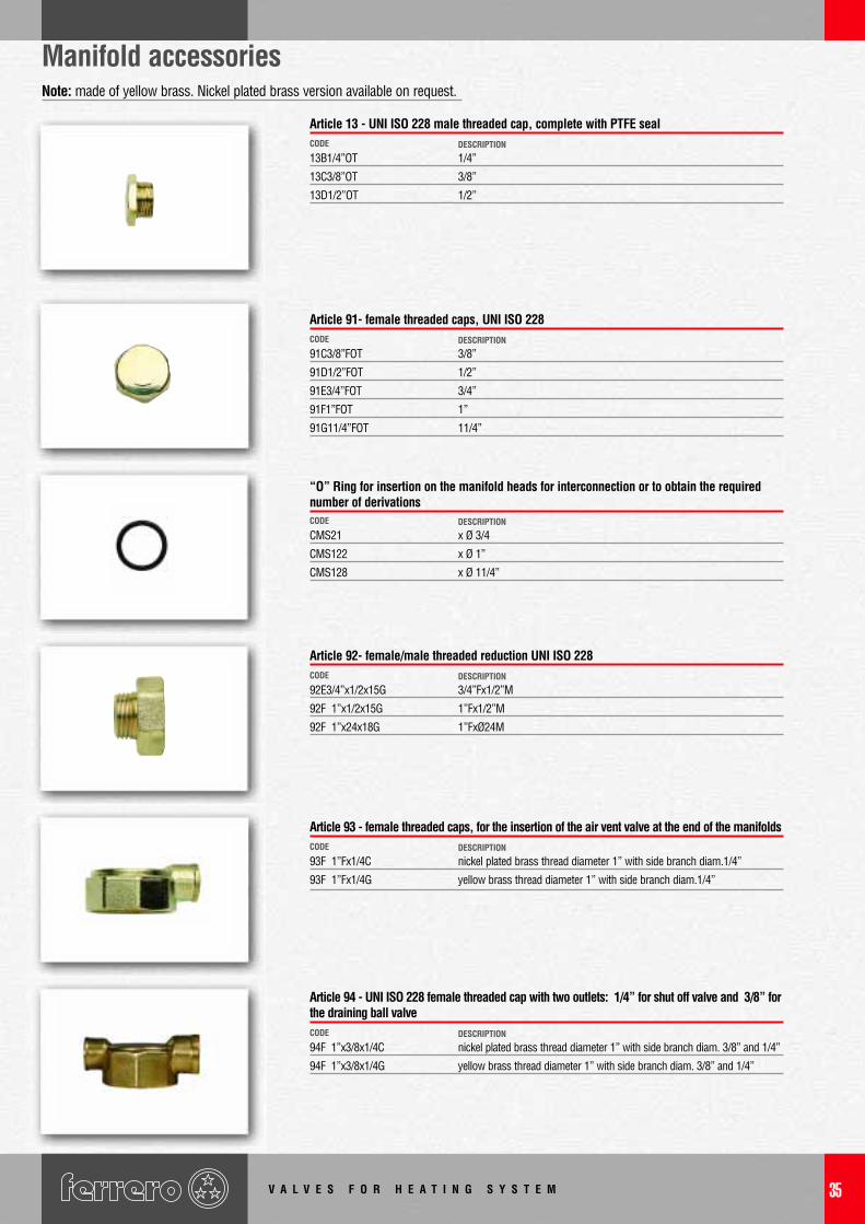
Manifold accessoriesNote: made of yellow brass. Nickel plated brass version available on request.
13B1/4”OT 1/4”
13C3/8”OT 3/8”
13D1/2”OT 1/2”
CODE DESCRIPTION
Article 13 - UNI ISO 228 male threaded cap, complete with PTFE seal
CMS21 x Ø 3/4
CMS122 x Ø 1”
CMS128 x Ø 11/4”
CODE DESCRIPTION
“O” Ring for insertion on the manifold heads for interconnection or to obtain the requirednumber of derivations
91C3/8”FOT 3/8”
91D1/2”FOT 1/2”
91E3/4”FOT 3/4”
91F1”FOT 1”
91G11/4”FOT 11/4”
CODE DESCRIPTION
Article 91- female threaded caps, UNI ISO 228
92E3/4”x1/2x15G 3/4”Fx1/2”M
92F 1”x1/2x15G 1”Fx1/2”M
92F 1”x24x18G 1”FxØ24M
CODE DESCRIPTION
Article 92- female/male threaded reduction UNI ISO 228
93F 1”Fx1/4C nickel plated brass thread diameter 1” with side branch diam.1/4”
93F 1”Fx1/4G yellow brass thread diameter 1” with side branch diam.1/4”
CODE DESCRIPTION
Article 93 - female threaded caps, for the insertion of the air vent valve at the end of the manifolds
94F 1”x3/8x1/4C nickel plated brass thread diameter 1” with side branch diam. 3/8” and 1/4”
94F 1”x3/8x1/4G yellow brass thread diameter 1” with side branch diam. 3/8” and 1/4”
CODE DESCRIPTION
Article 94 - UNI ISO 228 female threaded cap with two outlets: 1/4” for shut off valve and 3/8” forthe draining ball valve
V A L V E S F O R H E A T I N G S Y S T E M36
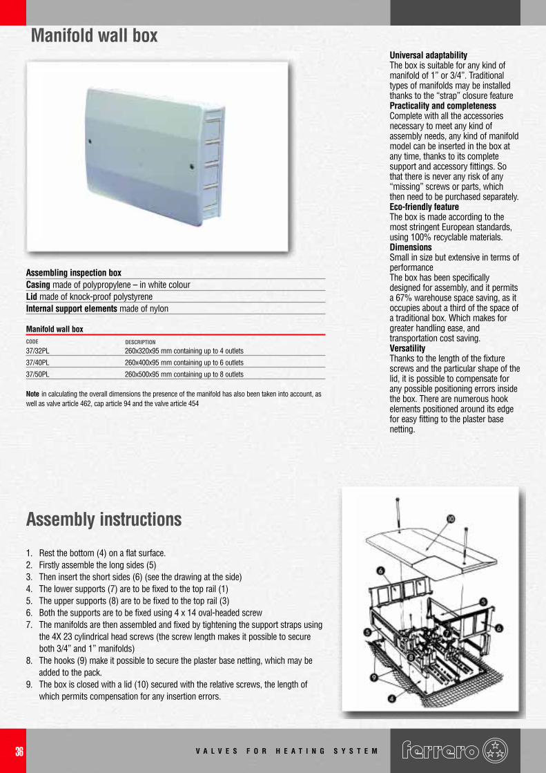
Manifold wall box
Assembling inspection boxCasing made of polypropylene – in white colourLid made of knock-proof polystyreneInternal support elements made of nylon
Assembly instructions
1. Rest the bottom (4) on a flat surface.2. Firstly assemble the long sides (5)3. Then insert the short sides (6) (see the drawing at the side)4. The lower supports (7) are to be fixed to the top rail (1)5. The upper supports (8) are to be fixed to the top rail (3)6. Both the supports are to be fixed using 4 x 14 oval-headed screw7. The manifolds are then assembled and fixed by tightening the support straps using
the 4X 23 cylindrical head screws (the screw length makes it possible to secureboth 3/4” and 1” manifolds)
8. The hooks (9) make it possible to secure the plaster base netting, which may beadded to the pack.
9. The box is closed with a lid (10) secured with the relative screws, the length ofwhich permits compensation for any insertion errors.
37/32PL 260x320x95 mm containing up to 4 outlets
37/40PL 260x400x95 mm containing up to 6 outlets
37/50PL 260x500x95 mm containing up to 8 outlets
CODE DESCRIPTION
Manifold wall box
Note in calculating the overall dimensions the presence of the manifold has also been taken into account, aswell as valve article 462, cap article 94 and the valve article 454
Universal adaptabilityThe box is suitable for any kind ofmanifold of 1” or 3/4”. Traditionaltypes of manifolds may be installedthanks to the “strap” closure feature Practicality and completenessComplete with all the accessoriesnecessary to meet any kind ofassembly needs, any kind of manifoldmodel can be inserted in the box atany time, thanks to its completesupport and accessory fittings. Sothat there is never any risk of any“missing” screws or parts, whichthen need to be purchased separately.Eco-friendly featureThe box is made according to themost stringent European standards,using 100% recyclable materials.DimensionsSmall in size but extensive in terms ofperformanceThe box has been specificallydesigned for assembly, and it permitsa 67% warehouse space saving, as itoccupies about a third of the space ofa traditional box. Which makes forgreater handling ease, andtransportation cost saving.VersatilityThanks to the length of the fixturescrews and the particular shape of thelid, it is possible to compensate forany possible positioning errors insidethe box. There are numerous hookelements positioned around its edgefor easy fitting to the plaster basenetting.
V A L V E S F O R H E A T I N G S Y S T E M 37
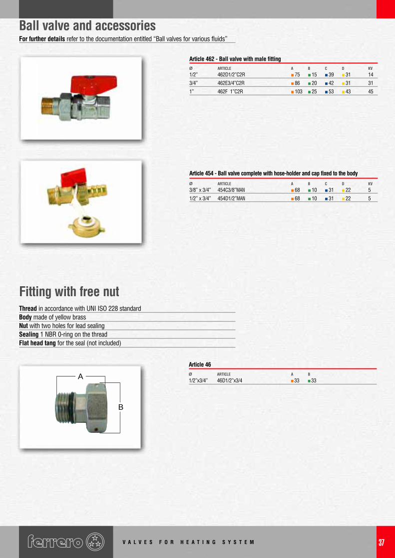
Ball valve and accessoriesFor further details refer to the documentation entitled “Ball valves for various fluids”
1/2” 462D1/2”C2R 75 15 39 31 14
3/4” 462E3/4”C2R 86 20 42 31 31
1” 462F 1”C2R 103 25 53 43 45
Ø ARTICLE A B C D KV
Article 462 - Ball valve with male fitting
3/8” x 3/4” 454C3/8”MAN 68 10 31 22 5
1/2” x 3/4” 454D1/2”MAN 68 10 31 22 5
Ø ARTICLE A B C D KV
Article 454 - Ball valve complete with hose-holder and cap fixed to the body
Fitting with free nutThread in accordance with UNI ISO 228 standardBody made of yellow brassNut with two holes for lead sealingSealing 1 NBR 0-ring on the threadFlat head tang for the seal (not included)
Ø ARTICLE A B
1/2”x3/4” 46D1/2”x3/4 33 33
Article 46
A
B
V A L V E S F O R H E A T I N G S Y S T E M38
For the balancing of the columns ofthe central heating and waterdistribution systems
1/2” 112D1/2” 28 62 43 69 60
3/4” 112E3/4” 28 66 45 72 60
1” 112F 1” 33 80 49 82 60
11/4” 112G11/4” 42 91 54 93 75
11/2” 112H11/2” 45 97 59 98 75
2” 112I 2” 57 125 62 114 75
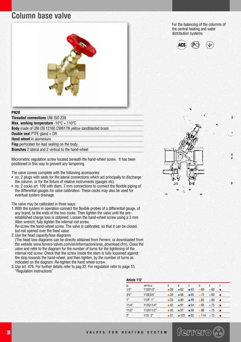
ARTICLE CBA D E F
PN20Threaded connections UNI ISO 228Max. working temperature -10°C + 110°CBody made of UNI EN 12165 CW617N yellow sandblasted brassDouble seal PTFE gland + ORHand wheel in aluminiumFlap perforated for lead sealing on the bodyBranches 2 lateral and 2 vertical to the hand-wheel
Micrometric regulation screw located beneath the hand-wheel screw. It has beenpositioned in this way to prevent any tampering.
The valve comes complete with the following accessories:• no. 2 plugs with seals for the lateral connections which act principally to discharge
the column, or for the fixture of relative instruments (gauges etc)• no. 2 cocks art. 109 with diam. 7 mm connections to connect the flexible piping of
the differential gauges for valve calibration. These cocks may also be used foreventual system drainage.
The valve may be calibrated in three ways:1.With the system in operation connect the flexible probes of a differential gauge, of
any brand, to the ends of the two cocks. Then tighten the valve until the pre-established charge loss is obtained. Loosen the hand-wheel screw using a 3 mmAllen wrench, fully tighten the internal rod screw.Re-screw the hand-wheel screw. The valve is calibrated, so that it can be closed,but not opened over the fixed value.
2.Use the head capacity/loss diagrams(The head loss diagrams can be directly obtained from Ferrero, or downloaded fromthe website www.ferrero-valves.com/en/informazioni/area_download.cfm). Close thevalve and refer to the diagram for the number of turns for the tightening of theinternal rod screw. Check that the screw inside the stem is fully loosened againstthe stop towards the hand-wheel, and then tighten, by the number of turns asindicated on the diagram. Re-tighten the hand wheel screw.
3.Use art. 476. For further details refer to pag.22. For regulation refer to page 15“Regulation instructions”
Column base valve
ACS
Article 112Ø
V A L V E S F O R H E A T I N G S Y S T E M 39
Accessories for column base valves
1/4” 108B1/4” 44 50 21Ø ARTICLE CBA D E F
Article 108 - Drainage cock with hand-wheel ø 1/4” has 1 ORing inrubber inserted on the threaded end
1/4” 109B1/4” 32 21
3/8” 109C3/8” 32 21
Ø ARTICLE CBA D E F
Article 109 - Drainage cock diam. 1/4” with 1 rubber ORing insertedon the threaded end
9C3/8”OT yellow brass
9D1/2OT yellow brass
9E3/4”OT yellow brass
9F 1”OT yellow brass
CODE DESCRIPTION
9C3/8” nickel plated brass
9D1/2” nickel plated brass
9E3/4” nickel plated brass
9F 1” nickel plated brass
CODE DESCRIPTION
10C3/8”OT yellow brass
10D1/2OT yellow brass
10E3/4”OT yellow brass
10F 1”OT yellow brass
CODE DESCRIPTION
10C3/8” nickel plated brass
10D1/2” nickel plated brass
10E3/4” nickel plated brass
10F 1” nickel plated brass
CODE DESCRIPTION
9C3/8”POT yellow brass
9D1/2POT yellow brass
9E3/4”POT yellow brass
9F 1”POT yellow brass
CODE DESCRIPTION
9C3/8”P nickel plated brass
9D1/2”P nickel plated brass
9E3/4”P nickel plated brass
9F 1”P nickel plated brass
CODE DESCRIPTION
10C3/8”POT yellow brass
10D1/2POT yellow brass
10E3/4”POT yellow brass
10F 1”POT yellow brass
CODE DESCRIPTION
10C3/8”P nickel plated brass
10D1/2”P nickel plated brass
10E3/4”P nickel plated brass
10F 1”P nickel plated brass
CODE DESCRIPTION
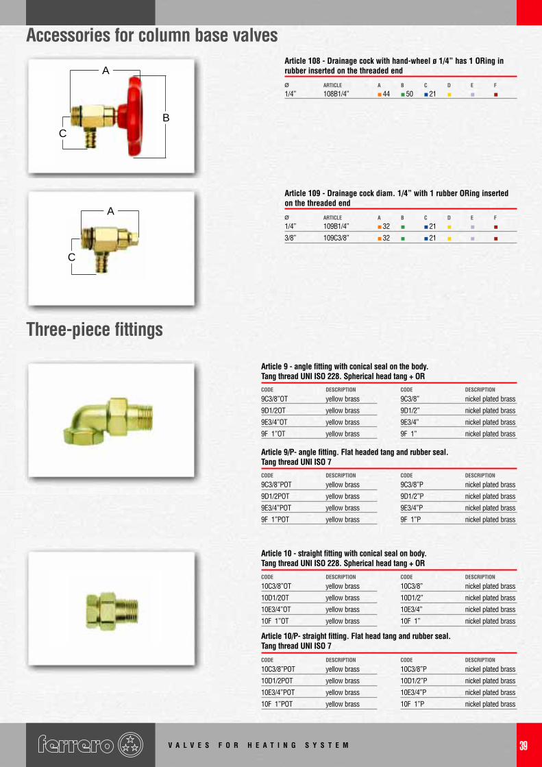
Article 9 - angle fitting with conical seal on the body.Tang thread UNI ISO 228. Spherical head tang + OR
Article 10/P- straight fitting. Flat head tang and rubber seal.Tang thread UNI ISO 7
Article 9/P- angle fitting. Flat headed tang and rubber seal.Tang thread UNI ISO 7
Article 10 - straight fitting with conical seal on body.Tang thread UNI ISO 228. Spherical head tang + OR
B
A
C
A
C
Three-piece fittings
V A L V E S F O R H E A T I N G S Y S T E M40
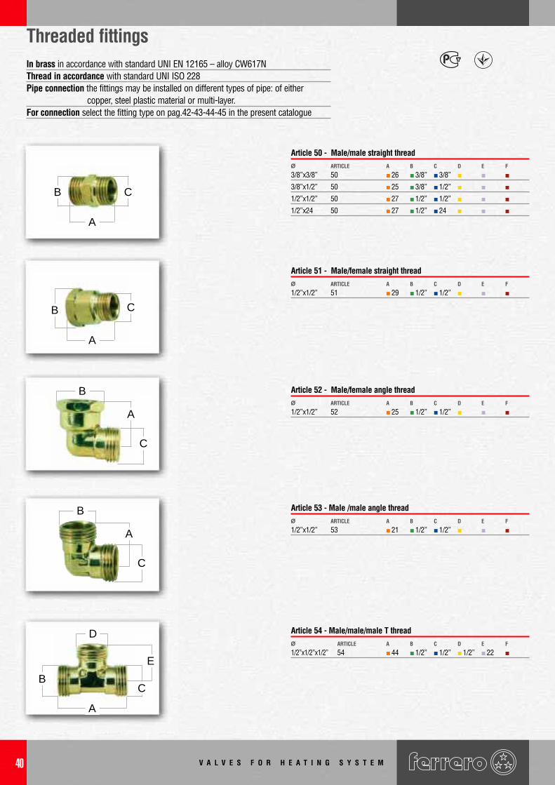
Threaded fittings
3/8”x3/8” 50 26 3/8” 3/8”
3/8”x1/2” 50 25 3/8” 1/2”
1/2”x1/2” 50 27 1/2” 1/2”
1/2”x24 50 27 1/2” 24
Ø ARTICLE CBA D E F
Article 50 - Male/male straight thread
1/2”x1/2” 51 29 1/2” 1/2”Ø ARTICLE CBA D E F
Article 51 - Male/female straight thread
1/2”x1/2” 52 25 1/2” 1/2”Ø ARTICLE CBA D E F
Article 52 - Male/female angle thread
1/2”x1/2” 53 21 1/2” 1/2”Ø ARTICLE CBA D E F
Article 53 - Male /male angle thread
1/2”x1/2”x1/2” 54 44 1/2” 1/2” 1/2” 22Ø ARTICLE CBA D E F
Article 54 - Male/male/male T thread
In brass in accordance with standard UNI EN 12165 – alloy CW617NThread in accordance with standard UNI ISO 228Pipe connection the fittings may be installed on different types of pipe: of either
copper, steel plastic material or multi-layer.For connection select the fitting type on pag.42-43-44-45 in the present catalogue
A
B C
A
A
B
B C
C
E
B
A
C
D
B
A
C
V A L V E S F O R H E A T I N G S Y S T E M 41
506D1/2”G20 1/2”x20 41 20 35
506E3/4”G25 3/4”x25 46 25 39
506F1”G32 1”x32 52 33 49
506G11/4”G40 11/4”x40 63 41 61
506H11/2”G50 11/2”x50 74 51 73
CODE Ø
Article 506 - Fitting for “PVC-PE” on one side, female threaded connection UNI ISO 228 on the other side
Plastic pipe fittingsMaximum working pressure 16 barTemperature limit from -10°C to + 110°CHydraulic testing at 25 barThe fitting is suitable for use with PE and PVC piping, for water and non-aggressiveliquid distribution.With the (compulsory) addition of reinforcement article 512 it is also suitable for thedistribution systems of certain gases.Body made of brass in accordance with UNI EN 12165 standard.O ring made of NBRFeatures: the brass ogive ensures a more secure and rigid fixture than that possible usingstandard plastic rings. The ring is sectioned in a slanting direction to guarantee sturdyfixture along the entire pipe surface. The cap nut covers and protects the entire jointthereby ensuring that no earth or foreign bodies can enter and block the thread
Assembly instructions1. Cut the pipe in a perpendicular manner, then remove any burrs or sharp edges
causes by the cut.2. Loosen the nut. DO NOT DISMANTLE THE FITTING (drawing 1).3. Securely insert the plastic pipe4. Tighten the nut• should it be necessary to completely dismantle the fitting, ensure that this operation is
undertaken in a clean environment, or in any event try and prevent any dirt, sand orfibers from damaging the fitting, which will jeopardize the seal potential. Avoid pressingor damaging the brass ring or scratching the sealing O-ring. Note: do not overturn thesealing ring, the conical side must press against the nut cone (drawing 2).
• Should it be necessary to reinforce the plastic pipe, it is possible to insert thereinforcement element article 512.
Note: to facilitate the assembly, the pipe must not be excessively oval in form
20x3,3 512D20-3,3
25x3,3 512E25-3,3
32x3,5 512F32-3,5
40x3,7 512G40-3,7
50x4,6 512H50-4,6
Ø ARTICLE
Article 512: brass inserts for thereinforcement of the plastic pipe
507D1/2”G20 1/2”x20 42 20 35
507E3/4”G25 3/4”x25 46 25 40
507F1”G32 1”x32 53 33 49
507G11/4”G40 11/4”x40 64 41 61
507H11/2”G50 11/2”x50 75 51 73
CODE Ø
Article 507 - Fitting for “PVC-PE” on one side, male threaded connection UNI ISO 228 on the other side
CHBA
CHBA
DRAWING 1
DRAWING 2
42
63D1/2”x12x8C 1/2” 12 8
63D1/2”x15x10C 1/2” 15 10
63D1/2”x15x11C 1/2” 15 11
63D1/2”x16x12C 1/2” 16 12
63D1/2”x18x13C 1/2” 18 13
63D1/2”x18x14C 1/2” 18 14
63D1/2”x20x15C 1/2” 20 15
63D1/2”x20x16C 1/2” 20 16
CODE
Article 63 - Fitting with female UNI ISO 228 thread. Complete with nut and cut brass ogive
61D1/2”x12x8C 1/2” 12 8
61D1/2”x12x10C 1/2” 12 10
61D1/2”x15x10C 1/2” 15 10
61D1/2”x15x11C 1/2” 15 11
61D1/2”x16x12C 1/2” 16 12
61D1/2”x16x13C 1/2” 16 13
61D24x14x10C 24 14 10
61D24x15x10C 24 15 10
61D24x16x12C 24 16 12
61D24x18x13C 24 18 13
61D24X18X14C 24 18 14
CODE
Article 61- for the connection of our valves to the plastic pipes.Consisting of 3 piece: an internal probe with 1 “O” R, a cut ogive and a nut
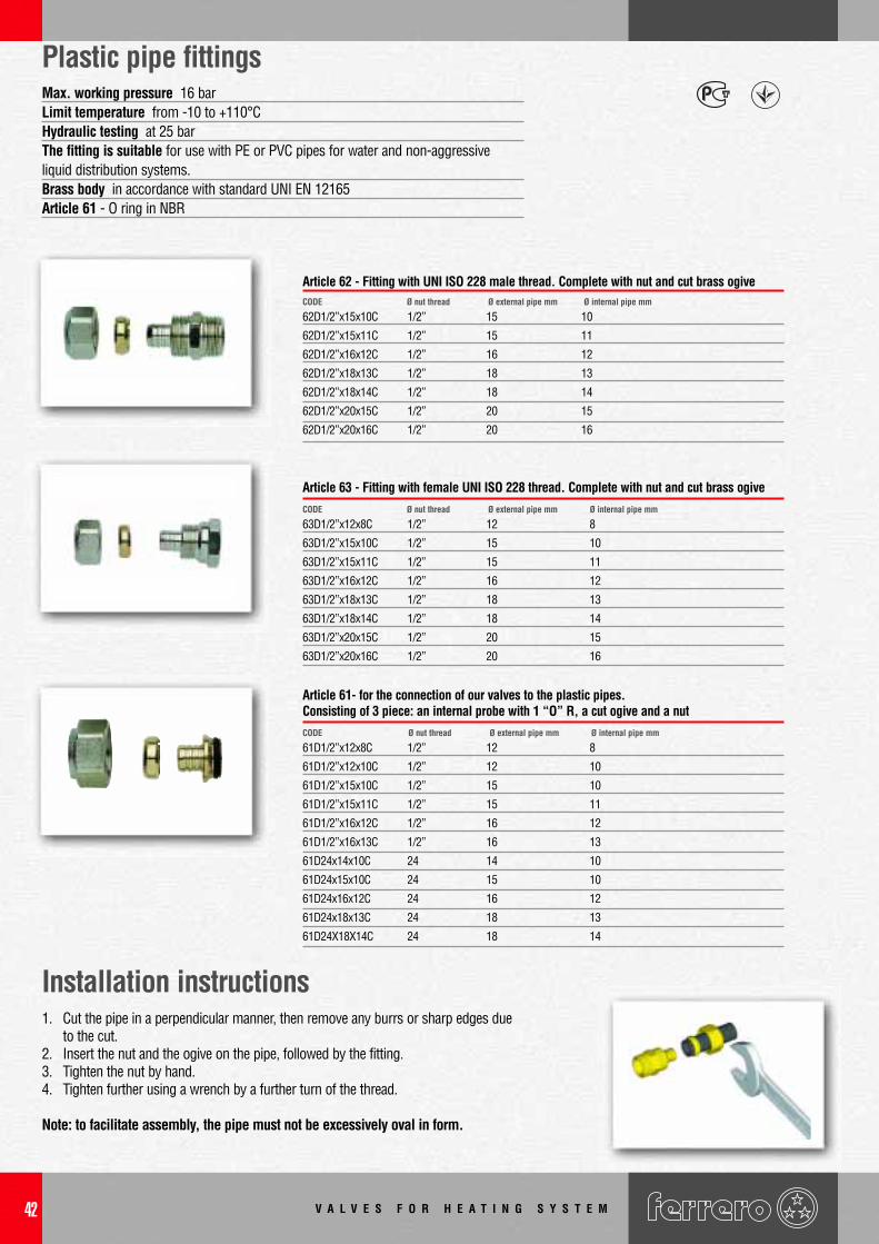
Plastic pipe fittingsMax. working pressure 16 barLimit temperature from -10 to +110°CHydraulic testing at 25 barThe fitting is suitable for use with PE or PVC pipes for water and non-aggressiveliquid distribution systems.Brass body in accordance with standard UNI EN 12165Article 61 - O ring in NBR
Installation instructions1. Cut the pipe in a perpendicular manner, then remove any burrs or sharp edges due
to the cut.2. Insert the nut and the ogive on the pipe, followed by the fitting.3. Tighten the nut by hand.4. Tighten further using a wrench by a further turn of the thread.
Note: to facilitate assembly, the pipe must not be excessively oval in form.
Ø nut thread Ø internal pipe mmØ external pipe mm
Ø nut thread Ø internal pipe mmØ external pipe mm
62D1/2”x15x10C 1/2” 15 10
62D1/2”x15x11C 1/2” 15 11
62D1/2”x16x12C 1/2” 16 12
62D1/2”x18x13C 1/2” 18 13
62D1/2”x18x14C 1/2” 18 14
62D1/2”x20x15C 1/2” 20 15
62D1/2”x20x16C 1/2” 20 16
CODE Ø nut thread Ø internal pipe mm
Article 62 - Fitting with UNI ISO 228 male thread. Complete with nut and cut brass ogiveØ external pipe mm
V A L V E S F O R H E A T I N G S Y S T E M
V A L V E S F O R H E A T I N G S Y S T E M 43
Multi-layer pipe fittings
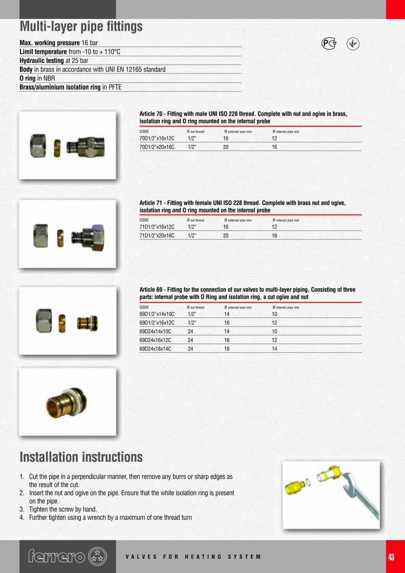
Installation instructions
Max. working pressure 16 barLimit temperature from -10 to + 110°CHydraulic testing at 25 barBody in brass in accordance with UNI EN 12165 standardO ring in NBRBrass/aluminium isolation ring in PFTE
70D1/2”x16x12C 1/2” 16 12
70D1/2”x20x16C 1/2” 20 16
CODE
Article 70 - Fitting with male UNI ISO 228 thread. Complete with nut and ogive in brass,isolation ring and O ring mounted on the internal probe
71D1/2”x16x12C 1/2” 16 12
71D1/2”x20x16C 1/2” 20 16
CODE
Article 71 - Fitting with female UNI ISO 228 thread. Complete with brass nut and ogive,isolation ring and O ring mounted on the internal probe
69D1/2”x14x10C 1/2” 14 10
69D1/2”x16x12C 1/2” 16 12
69D24x14x10C 24 14 10
69D24x16x12C 24 16 12
69D24x18x14C 24 18 14
CODE
Article 69 - Fitting for the connection of our valves to multi-layer piping, Consisting of threeparts: internal probe with O Ring and isolation ring, a cut ogive and nut
1. Cut the pipe in a perpendicular manner, then remove any burrs or sharp edges asthe result of the cut.
2. Insert the nut and ogive on the pipe. Ensure that the white isolation ring is presenton the pipe.
3. Tighten the screw by hand.4. Further tighten using a wrench by a maximum of one thread turn
Ø nut thread Ø internal pipe mmØ external pipe mm
Ø nut thread Ø internal pipe mmØ external pipe mm
Ø nut thread Ø internal pipe mmØ external pipe mm
V A L V E S F O R H E A T I N G S Y S T E M44
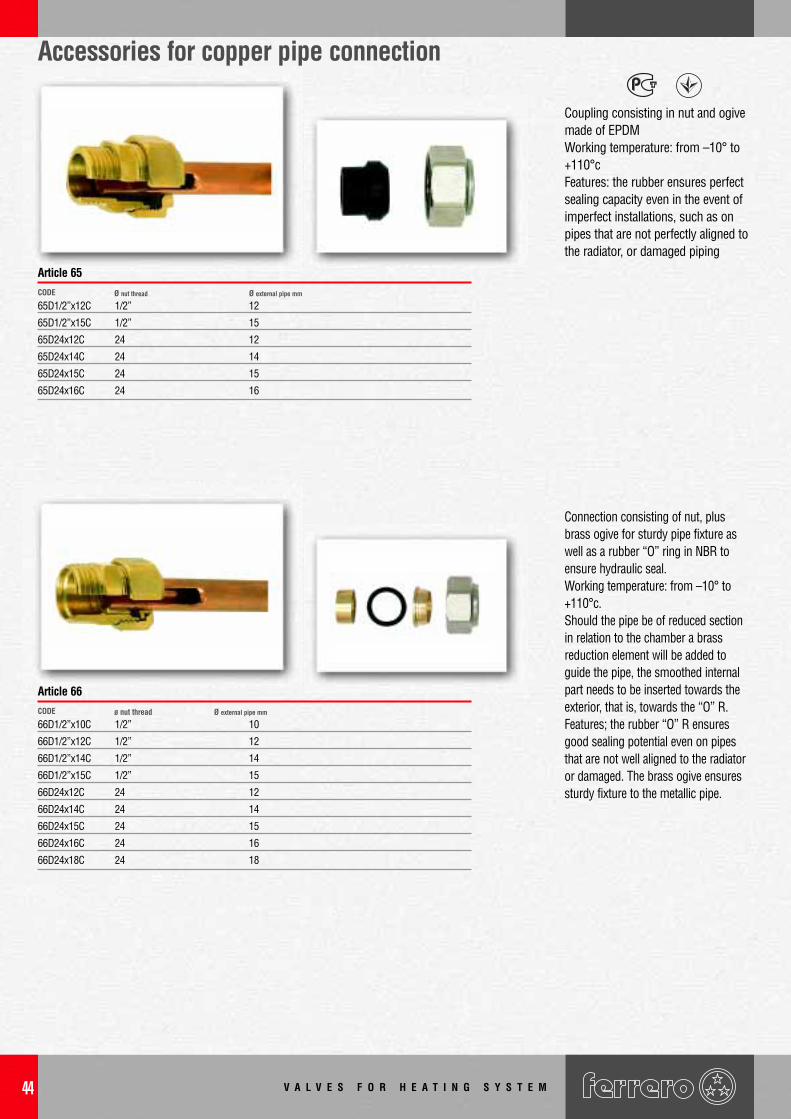
Coupling consisting in nut and ogivemade of EPDMWorking temperature: from –10° to+110°cFeatures: the rubber ensures perfectsealing capacity even in the event ofimperfect installations, such as onpipes that are not perfectly aligned tothe radiator, or damaged piping
65D1/2”x12C 1/2” 12
65D1/2”x15C 1/2” 15
65D24x12C 24 12
65D24x14C 24 14
65D24x15C 24 15
65D24x16C 24 16
CODE Ø nut thread Ø external pipe mm
Ø external pipe mm
Article 65
Connection consisting of nut, plusbrass ogive for sturdy pipe fixture aswell as a rubber “O” ring in NBR toensure hydraulic seal.Working temperature: from –10° to+110°c.Should the pipe be of reduced sectionin relation to the chamber a brassreduction element will be added toguide the pipe, the smoothed internalpart needs to be inserted towards theexterior, that is, towards the “O” R.Features; the rubber “O” R ensuresgood sealing potential even on pipesthat are not well aligned to the radiatoror damaged. The brass ogive ensuressturdy fixture to the metallic pipe.
CODE ø nut thread
Article 66
Accessories for copper pipe connection
66D1/2”x10C 1/2” 10
66D1/2”x12C 1/2” 12
66D1/2”x14C 1/2” 14
66D1/2”x15C 1/2” 15
66D24x12C 24 12
66D24x14C 24 14
66D24x15C 24 15
66D24x16C 24 16
66D24x18C 24 18
V A L V E S F O R H E A T I N G S Y S T E M 45
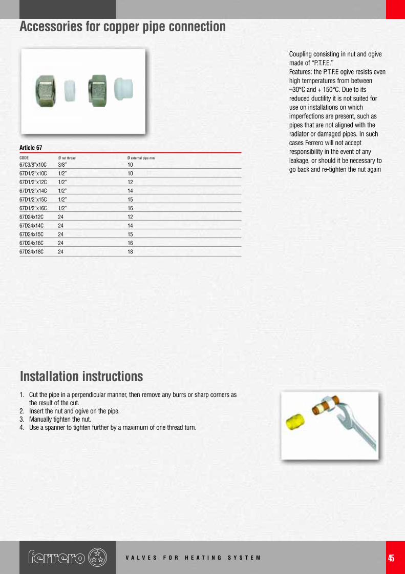
Installation instructions1. Cut the pipe in a perpendicular manner, then remove any burrs or sharp corners as
the result of the cut.2. Insert the nut and ogive on the pipe.3. Manually tighten the nut.4. Use a spanner to tighten further by a maximum of one thread turn.
CODE
Article 67
Coupling consisting in nut and ogivemade of “P.T.F.E.”Features: the P.T.F.E ogive resists evenhigh temperatures from between–30°C and + 150°C. Due to itsreduced ductility it is not suited foruse on installations on whichimperfections are present, such aspipes that are not aligned with theradiator or damaged pipes. In suchcases Ferrero will not acceptresponsibility in the event of anyleakage, or should it be necessary togo back and re-tighten the nut again
Accessories for copper pipe connection
Ø nut thread Ø external pipe mm
67C3/8”x10C 3/8” 10
67D1/2”x10C 1/2” 10
67D1/2”x12C 1/2” 12
67D1/2”x14C 1/2” 14
67D1/2”x15C 1/2” 15
67D1/2”x16C 1/2” 16
67D24x12C 24 12
67D24x14C 24 14
67D24x15C 24 15
67D24x16C 24 16
67D24x18C 24 18
V A L V E S F O R H E A T I N G S Y S T E M46
Heating valve spare parts
R69 female thread diam.1/2” for 3/8” diam. valve
R70 female thread diam.3/4” for 1/2” diam. valve
R71 female thread diam.1” for 3/4” diam. valve
R72 female thread diam. 11/4” for 1” diam. valve
CODE DESCRIPTION
Nuts
R2854/1OR 3/8”
R2319/1OR 1/2”
R2853/1OR 3/4”
R77/1OR 1”
CODE Ø
Spherical head tang with O Ring inserted on the head, UNI ISO 228 thread (UNI ISO 7 on request)
R2854 3/8”
R2319 1/2”
R2853 3/4”
CODE
Spherical head tang with O Ring inserted on the head and O Ring on the UNI ISO 228 thread (ISO 7 on request)
R460 for articles 5-6 Ø 3/8”-3/4” - art. 17-18-467-468 Ø 3/8”-1/2”
R710 for articles 1-2-15-16 Ø 3/8”-3/4” - art. 38-39
R716 for articles 1-2 Ø 1”
R94 for articles 29-32 Ø 1/2”-1” - art. 3-4-27-28
R18 for articles 161-162-165-166 Ø 3/8” -1/2”
R67 for articles 7-8-19-20-469-470 Ø 3/8” - 3/4”
CODE DESCRIPTION
Radiator valve hand-wheels
R453 for handwheel R460
R722 for handwheel R710-R716-R94
CODE DESCRIPTION
Radiator valve screws
Ø
V A L V E S F O R H E A T I N G S Y S T E M 47
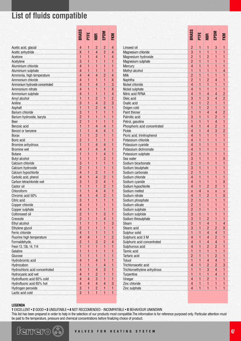
List of fluids compatible
Acetic acid, glacial 4 1 2 2 4Acetic anhydride X 1 4 2 4Acetone 1 1 4 1 4Acetylene 3 1 1 1 1Aluminium chloride 4 1 1 1 1Aluminium sulphate 4 1 1 1 1Ammonia, high temperature 4 4 4 2 4Ammonium chloride 4 1 1 1 XAmmonium hydroxide concentrated 4 1 4 1 3Ammonium nitrate 4 1 1 1 XAmmonium sulphate 4 1 1 1 4Amyl alcohol 1 1 2 1 2Aniline 3 1 4 2 3Asphalt 1 1 2 4 1Barium chloride 3 1 1 1 1Barium hydroxide, baryta 2 1 1 1 1Beer 2 1 1 1 1Benzoic acid 1 1 4 4 1Benzol or benzene 1 1 4 4 1Borax 1 1 2 1 1Boric acid 2 1 1 1 1Bromine anhydrous 1 1 4 4 1Bromine wet 4 1 4 4 1Butane 1 1 1 4 1Butyl alcohol 1 1 1 2 1Calcium chloride 3 1 1 1 1Calcium hydroxide 2 1 1 1 1Calcium hypochlorite 4 1 2 1 1Carbolic acid, phenol 4 1 4 2 1Carbon tetrachloride wet 3 1 2 4 1Castor oil 1 1 1 2 1Chloroform 1 1 4 4 1Chromic acid 50% 4 1 4 2 1Citric acid 3 1 1 1 1Copper chloride 4 1 1 1 1Copper sulphate 4 1 1 1 1Cottonseed oil 2 1 1 3 1Creosote 2 1 1 4 1Ethyl alcohol 1 1 1 1 3Ethylene glycol 2 1 1 1 1Ferric chloride 4 1 1 1 1Fluorine high temperature 4 4 1 1 2Formaldehyde, 2 1 3 2 4Freon 13, 13b, 14, 114 1 1 1 1 1Gelatine 1 1 1 1 1Glucose 1 1 1 1 1Hydrobromic acid 4 1 4 1 1Hydrocabon 1 1 1 4 1Hydrochloric acid concentrated 4 1 4 3 1Hydrocyanic acid wet 4 1 2 1 1Hydrofluoric acid 65% cold 4 4 3 1 1Hydrofluoric acid 65% hot 4 4 4 4 3Hydrogen peroxide 3 1 2 1 1Lactic acid cold 3 1 1 1 1
Linseed oil 2 1 1 3 1Magnesium chloride 3 1 1 1 1Magnesium hydroxide 2 1 2 1 1Magnesium sulphate 2 1 1 1 1Mercury 4 1 1 1 1Methyl alcohol 1 1 1 1 4Milk 2 1 1 1 1Naphtha 2 1 2 4 1Nickel chloride 4 1 1 1 1Nickel sulphate 4 1 1 1 1Nitric acid RFNA 4 1 4 4 2Oleic acid 3 1 3 4 2Oxalic acid 4 1 2 1 1Oxigen cold 1 1 2 1 1Paint thinner 1 1 4 4 2Palmitic acid 3 1 1 2 1Petrol, gasoline 1 1 1 4 1Phosphoric acid concentrated 4 1 4 2 1Pickle 4 1 4 3 2Picric acid, trinitrophenol 4 1 1 1 1Potassium chloride 4 1 1 1 1Potassium cyanide 4 1 1 1 1Potassium dichromate 4 1 1 1 1Potassium sulphate 2 1 1 1 1Sea water 3 1 1 1 XSodium bicarbonate 2 1 1 1 1Sodium bisulphate 3 1 1 1 1Sodium carbonate 2 1 1 1 1Sodium chloride 4 1 1 1 1Sodium cyanide 4 1 1 1 XSodium hypochlorite 4 1 2 2 1Sodium melted x 4 x x xSodium nitrate 4 1 2 1 XSodium phosphate 2 1 1 1 1Sodium silicate 2 1 1 1 1Sodium sulphate 2 1 1 1 1Sodium sulphide 3 1 1 1 1Sodium thiosulphate 3 1 2 1 1Steam 3 1 4 1 4Stearic acid 3 1 2 2 XSulphur solid 1 1 4 4 1Sulphuric acid 3 M 4 1 4 2 1Sulphuric acid concentrated 4 1 4 4 1Sulphurous acid 4 1 2 2 1Tannic acid 1 1 1 1 1Tartaric acid 2 1 1 2 1Toluol 1 1 4 4 1Trichloroacetic acid 4 1 2 2 3Trichloroethylene anhydrous 1 1 3 4 1Turpentine 1 1 1 4 1Vinegar 4 1 2 1 1Zinc chloride 4 1 1 1 1Zinc sulphate 4 1 1 1 1
FKM
BRAS
S
PTFE
NBR
EPDM
FKM
BRAS
S
PTFE
NBR
EPDM
LEGENDA1 EXCELLENT • 2 GOOD • 3 UNSUITABLE • 4 NOT RECCOMENDED - INCOMPATIBLE • X BEHAVIOUR UNKNOWNThis list has been prepared in order to help in the selection of our products most compatible.The information is for reference purposed only. Particular attention mustbe paid to the temperature, pressure and chemical concentrations before finalizing choice of product.
V A L V E S F O R H E A T I N G S Y S T E M48
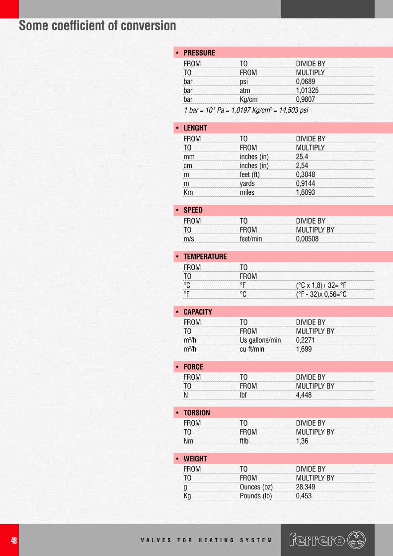
Some coefficient of conversion
• PRESSUREFROM TO DIVIDE BYTO FROM MULTIPLYbar psi 0,0689bar atm 1,01325bar Kg/cm 0,98071 bar = 10 5 Pa = 1,0197 Kg/cm2 = 14,503 psi
• LENGHTFROM TO DIVIDE BYTO FROM MULTIPLYmm inches (in) 25,4cm inches (in) 2,54m feet (ft) 0,3048m yards 0,9144Km miles 1,6093
• SPEEDFROM TO DIVIDE BYTO FROM MULTIPLY BYm/s feet/min 0,00508
• TEMPERATUREFROM TOTO FROM°C °F (°C x 1,8)+ 32= °F°F °C (°F - 32)x 0,56=°C
• CAPACITYFROM TO DIVIDE BYTO FROM MULTIPLY BY m3/h Us gallons/min 0,2271m3/h cu ft/min 1,699
• FORCEFROM TO DIVIDE BYTO FROM MULTIPLY BYN lbf 4,448
• TORSIONFROM TO DIVIDE BYTO FROM MULTIPLY BYNm ftlb 1,36
• WEIGHTFROM TO DIVIDE BYTO FROM MULTIPLY BY g Ounces (oz) 28,349Kg Pounds (lb) 0,453
V A L V E S F O R H E A T I N G S Y S T E M 49
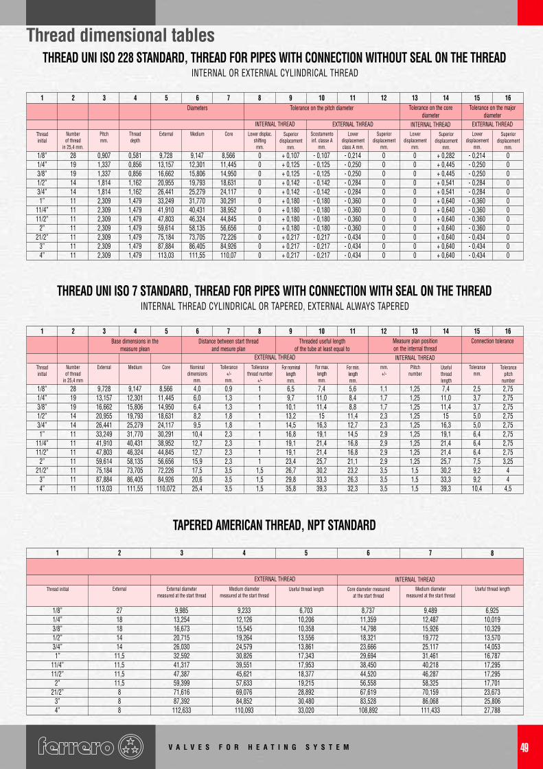
Thread dimensional tablesTHREAD UNI ISO 228 STANDARD, THREAD FOR PIPES WITH CONNECTION WITHOUT SEAL ON THE THREAD
INTERNAL OR EXTERNAL CYLINDRICAL THREAD
1Diameters
INTERNAL THREAD EXTERNAL THREAD INTERNAL THREADLower
displacementmm.
Superiordisplacement
mm.
Lowerdisplacementclass A mm.
Scostamentoinf. classe A
mm.
Superiordisplacement
mm.
Lower displac.shifting
mm.
CoreMediumExternalThreaddepth
Pitchmm.
Numberof thread
in 25,4 mm.
Threadinitial
1/8” 28 0,907 0,581 9,728 9,147 8,566 0 + 0,107 - 0,107 - 0,214 0 0 + 0,282 - 0,214 01/4” 19 1,337 0,856 13,157 12,301 11,445 0 + 0,125 - 0,125 - 0,250 0 0 + 0,445 - 0,250 03/8” 19 1,337 0,856 16,662 15,806 14,950 0 + 0,125 - 0,125 - 0,250 0 0 + 0,445 - 0,250 01/2” 14 1,814 1,162 20,955 19,793 18,631 0 + 0,142 - 0,142 - 0,284 0 0 + 0,541 - 0,284 03/4” 14 1,814 1,162 26,441 25,279 24,117 0 + 0,142 - 0,142 - 0,284 0 0 + 0,541 - 0,284 01” 11 2,309 1,479 33,249 31,770 30,291 0 + 0,180 - 0,180 - 0,360 0 0 + 0,640 - 0,360 0
11/4” 11 2,309 1,479 41,910 40,431 38,952 0 + 0,180 - 0,180 - 0,360 0 0 + 0,640 - 0,360 011/2” 11 2,309 1,479 47,803 46,324 44,845 0 + 0,180 - 0,180 - 0,360 0 0 + 0,640 - 0,360 0
2” 11 2,309 1,479 59,614 58,135 56,656 0 + 0,180 - 0,180 - 0,360 0 0 + 0,640 - 0,360 021/2” 11 2,309 1,479 75,184 73,705 72,226 0 + 0,217 - 0,217 - 0,434 0 0 + 0,640 - 0,434 0
3” 11 2,309 1,479 87,884 86,405 84,926 0 + 0,217 - 0,217 - 0,434 0 0 + 0,640 - 0,434 04” 11 2,309 1,479 113,03 111,55 110,07 0 + 0,217 - 0,217 - 0,434 0 0 + 0,640 - 0,434 0
Superiordisplacement
mm.
Lowerdisplacement
mm.
Superiordisplacement
mm.
EXTERNAL THREAD
Tolerance on the pitch diameter Tolerance on the corediameter
Tolerance on the majordiameter
2 3 4 5 6 7 8 9 10 11 12 13 14 15 16
THREAD UNI ISO 7 STANDARD, THREAD FOR PIPES WITH CONNECTION WITH SEAL ON THE THREADINTERNAL THREAD CYLINDRICAL OR TAPERED, EXTERNAL ALWAYS TAPERED
1Base dimensions in the
measure pleanEXTERNAL THREAD INTERNAL THREAD
Plitchnumber
mm.+/-
For min.lengthmm.
For max.length mm.
For nominal lengthmm.
Tollerancethread number
+/-
Tollerance+/-
mm.
Nominaldimensions
mm.
CoreMediumExternalNumberof thread
in 25,4 mm
Threadinitial
1/8” 28 9,728 9,147 8,566 4,0 0,9 1 6,5 7,4 5,6 1,1 1,25 7,4 2,5 2,751/4” 19 13,157 12,301 11,445 6,0 1,3 1 9,7 11,0 8,4 1,7 1,25 11,0 3,7 2,753/8” 19 16,662 15,806 14,950 6,4 1,3 1 10,1 11,4 8,8 1,7 1,25 11,4 3,7 2,751/2” 14 20,955 19,793 18,631 8,2 1,8 1 13,2 15 11,4 2,3 1,25 15 5,0 2,753/4” 14 26,441 25,279 24,117 9,5 1,8 1 14,5 16,3 12,7 2,3 1,25 16,3 5,0 2,751” 11 33,249 31,770 30,291 10,4 2,3 1 16,8 19,1 14,5 2,9 1,25 19,1 6,4 2,75
11/4” 11 41,910 40,431 38,952 12,7 2,3 1 19,1 21,4 16,8 2,9 1,25 21,4 6,4 2,7511/2” 11 47,803 46,324 44,845 12,7 2,3 1 19,1 21,4 16,8 2,9 1,25 21,4 6,4 2,75
2” 11 59,614 58,135 56,656 15,9 2,3 1 23,4 25,7 21,1 2,9 1,25 25,7 7,5 3,2521/2” 11 75,184 73,705 72,226 17,5 3,5 1,5 26,7 30,2 23,2 3,5 1,5 30,2 9,2 4
3” 11 87,884 86,405 84,926 20,6 3,5 1,5 29,8 33,3 26,3 3,5 1,5 33,3 9,2 44” 11 113,03 111,55 110,072 25,4 3,5 1,5 35,8 39,3 32,3 3,5 1,5 39,3 10,4 4,5
Usefulthreadlength
Tolerancemm.
Tolerancepitch
number
Distance between start threadand mesure plan
Threaded useful lengthof the tube at least equal to
Measure plan positionon the internal thread
Connection tolerance2 3 4 5 6 7 8 9 10 11 12 13 14 15 16
TAPERED AMERICAN THREAD, NPT STANDARD
1
EXTERNAL THREAD INTERNAL THREADMedium diameter
measured at the start threadCore diameter measured
at the start threadUseful thread lengthMedium diameter
measured at the start threadExternal diameter
measured at the start threadExternalThread initial
1/8” 27 9,985 9,233 6,703 8,737 9,489 6,9251/4” 18 13,254 12,126 10,206 11,359 12,487 10,0193/8” 18 16,673 15,545 10,358 14,798 15,926 10,3291/2” 14 20,715 19,264 13,556 18,321 19,772 13,5703/4” 14 26,030 24,579 13,861 23,666 25,117 14,0531” 11,5 32,592 30,826 17,343 29,694 31,461 16,787
11/4” 11,5 41,317 39,551 17,953 38,450 40,218 17,29511/2” 11,5 47,387 45,621 18,377 44,520 46,287 17,295
2” 11,5 59,399 57,633 19,215 56,558 58,325 17,70121/2” 8 71,616 69,076 28,892 67,619 70,159 23,673
3” 8 87,392 84,852 30,480 83,528 86,068 25,8064” 8 112,633 110,093 33,020 108,892 111,433 27,788
Useful thread length
2 3 4 5 6 7 8

V A L V E S F O R H E A T I N G S Y S T E M50
Notes

© 2004 - ALL RIGHTS RESERVEDAny part of this documentation can be reproduced or copied without authorization ofFerrero Rubinetterie (Italy)
& are trademarks registered by Ferrero Rubinetterie (Italy).

Ferrero Rubinetteria srlVia Dogliani, 84 - 12060 Farigliano (Cn) Italia
Tel. +39 0173 74 60 01 Fax +39 0173 76 405E-mail [email protected]:// www.ferrero-valves.com
CO
D.0
704/
INw
ww
.zet
agra
fica.
net_
stam
pa J
olly
graf