Embed Size (px)
DESCRIPTION
Reg. Reg. Reg. Reg. Reg. Reg. Reg. Reg. Reg. Reg. ALU. ALU. ALU. ALU. ALU. Ifetch. Ifetch. Ifetch. Ifetch. Ifetch. DMem. DMem. DMem. DMem. DMem. I n s t r. O r d e r. add r1 ,r2,r3. sub r4, r1 ,r3. and r6, r1 ,r7. or r8, r1 ,r9. xor r10, r1 ,r11. - PowerPoint PPT Presentation
Citation preview
CS252/PattersonLec 1.1
1/17/01
Time (clock cycles)
Forwarding to Avoid Data HazardFigure 3.10, Page 149 , CA:AQA 2e
Inst
r.
Order
add r1,r2,r3
sub r4,r1,r3
and r6,r1,r7
or r8,r1,r9
xor r10,r1,r11
Reg
ALU
DMemIfetch Reg
Reg
ALU
DMemIfetch Reg
Reg
ALU
DMemIfetch Reg
Reg
ALU
DMemIfetch Reg
Reg
ALU
DMemIfetch Reg
CS252/PattersonLec 1.2
1/17/01
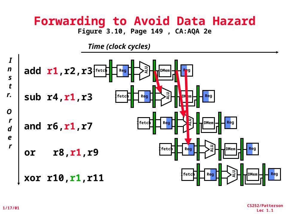
HW Change for ForwardingFigure 3.20, Page 161, CA:AQA 2e
MEM
/WR
ID/E
X
EX
/MEM
DataMemory
ALU
mux
mux
Registe
rs
NextPC
Immediate
mux
CS252/PattersonLec 1.3
1/17/01
Time (clock cycles)
Instr.
Order
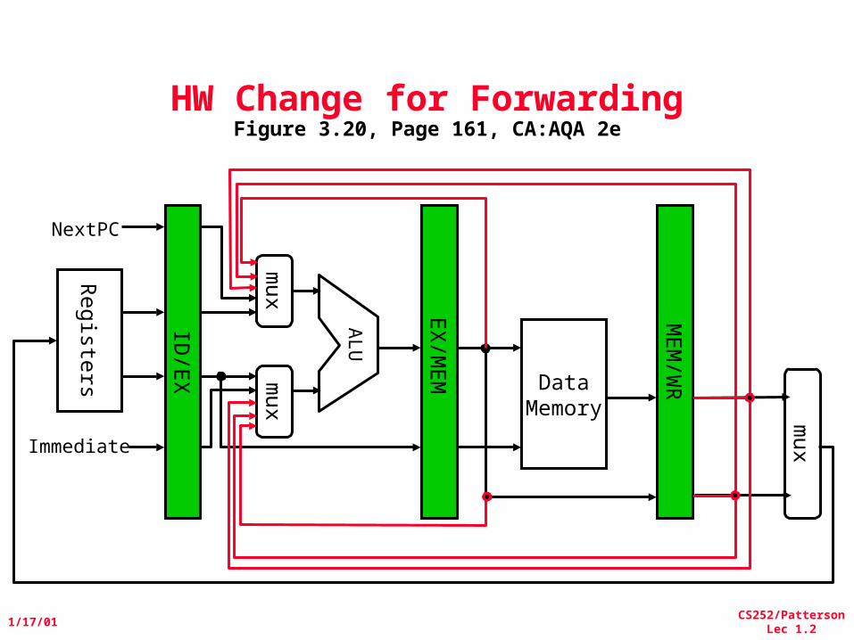
lw r1, 0(r2)
sub r4,r1,r6
and r6,r1,r7
or r8,r1,r9
Data Hazard Even with ForwardingFigure 3.12, Page 153 , CA:AQA 2e
Reg
ALU
DMemIfetch Reg
Reg
ALU
DMemIfetch Reg
Reg ALU
DMemIfetch Reg
Reg
ALU
DMemIfetch Reg
CS252/PattersonLec 1.4
1/17/01
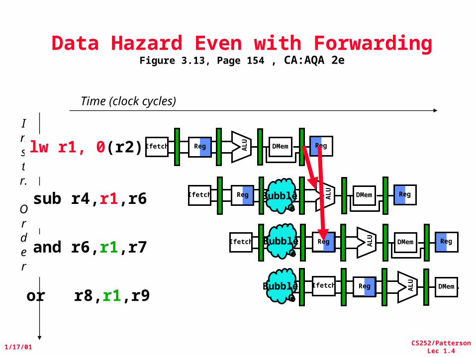
Data Hazard Even with ForwardingFigure 3.13, Page 154 , CA:AQA 2e
Time (clock cycles)
or r8,r1,r9
Instr.
Order
lw r1, 0(r2)
sub r4,r1,r6
and r6,r1,r7
Reg
ALU
DMemIfetch Reg
RegIfetch
ALU
DMem RegBubble
Ifetch
ALU
DMem RegBubble Reg
Ifetch
ALU
DMemBubble Reg
CS252/PattersonLec 1.5
1/17/01
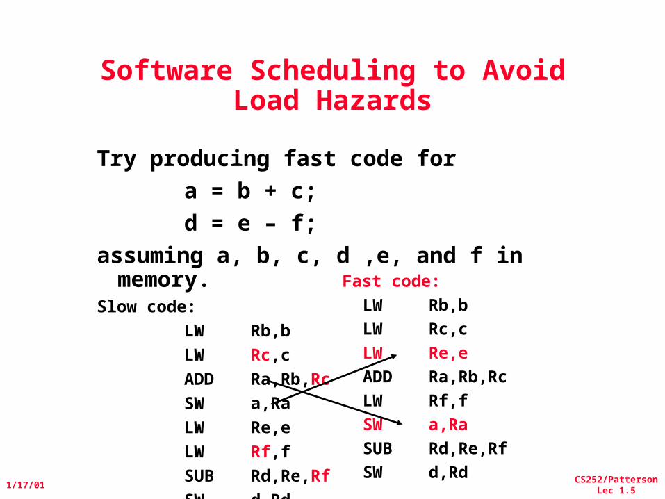
Try producing fast code for
a = b + c;
d = e – f;
assuming a, b, c, d ,e, and f in memory. Slow code:
LW Rb,b
LW Rc,c
ADD Ra,Rb,Rc
SW a,Ra
LW Re,e
LW Rf,f
SUB Rd,Re,Rf
SW d,Rd
Software Scheduling to Avoid Load Hazards
Fast code:
LW Rb,b
LW Rc,c
LW Re,e
ADD Ra,Rb,Rc
LW Rf,f
SW a,Ra
SUB Rd,Re,Rf
SW d,Rd
CS252/PattersonLec 1.6
1/17/01
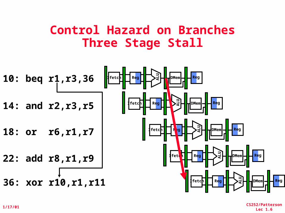
Control Hazard on BranchesThree Stage Stall
10: beq r1,r3,36
14: and r2,r3,r5
18: or r6,r1,r7
22: add r8,r1,r9
36: xor r10,r1,r11
Reg ALU
DMemIfetch Reg
Reg
ALU
DMemIfetch Reg
Reg ALU
DMemIfetch Reg
Reg
ALU
DMemIfetch Reg
Reg
ALU
DMemIfetch Reg
CS252/PattersonLec 1.7
1/17/01
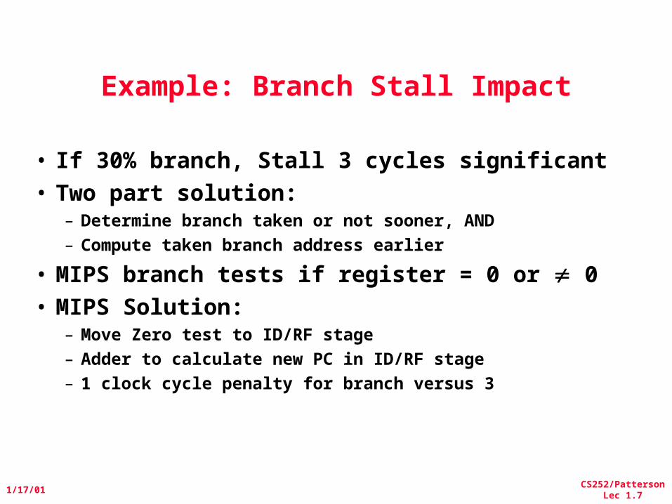
Example: Branch Stall Impact
• If 30% branch, Stall 3 cycles significant• Two part solution:
– Determine branch taken or not sooner, AND– Compute taken branch address earlier
• MIPS branch tests if register = 0 or 0• MIPS Solution:
– Move Zero test to ID/RF stage– Adder to calculate new PC in ID/RF stage– 1 clock cycle penalty for branch versus 3
CS252/PattersonLec 1.8
1/17/01
Ad
der
IF/ID
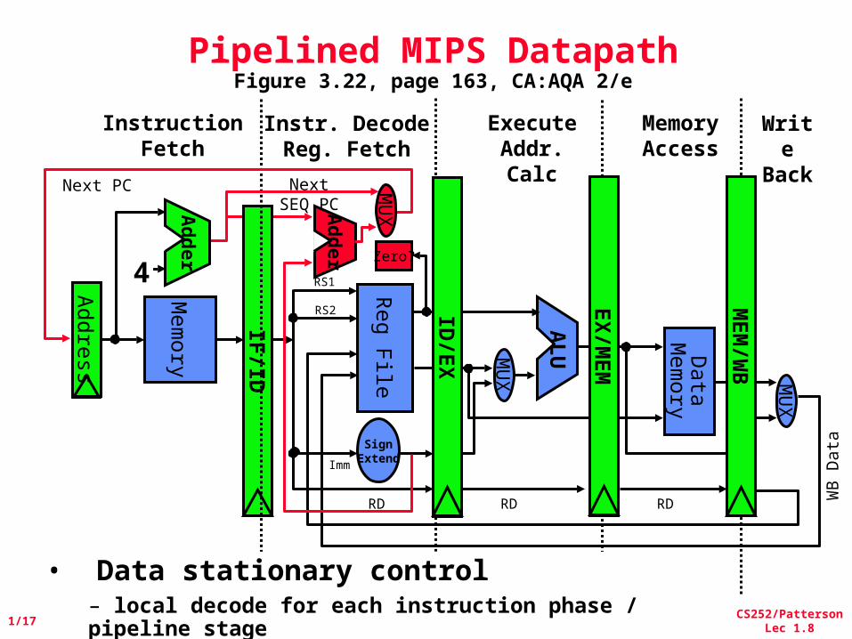
Pipelined MIPS DatapathFigure 3.22, page 163, CA:AQA 2/e
MemoryAccess
Write
Back
InstructionFetch
Instr. DecodeReg. Fetch
ExecuteAddr. Calc
ALU
Mem
ory
Reg File
MU
X
Data
Mem
ory
MU
X
SignExtend
Zero?
MEM
/WB
EX
/MEM
4
Ad
der
Next SEQ PC
RD RD RD WB
Data
• Data stationary control– local decode for each instruction phase / pipeline stage
Next PC
Addre
ss
RS1
RS2
ImmM
UX
ID/E
X
CS252/PattersonLec 1.9
1/17/01
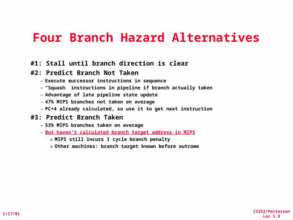
Four Branch Hazard Alternatives
#1: Stall until branch direction is clear
#2: Predict Branch Not Taken– Execute successor instructions in sequence– “Squash” instructions in pipeline if branch actually taken– Advantage of late pipeline state update– 47% MIPS branches not taken on average– PC+4 already calculated, so use it to get next instruction
#3: Predict Branch Taken– 53% MIPS branches taken on average– But haven’t calculated branch target address in MIPS
» MIPS still incurs 1 cycle branch penalty» Other machines: branch target known before outcome
CS252/PattersonLec 1.10
1/17/01
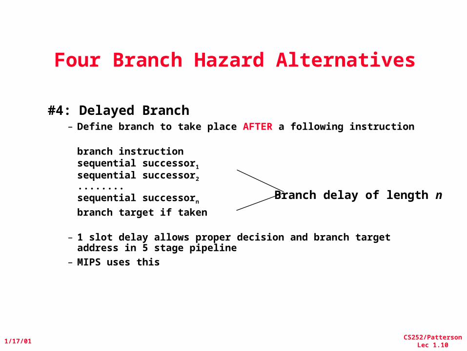
Four Branch Hazard Alternatives
#4: Delayed Branch– Define branch to take place AFTER a following instruction
branch instructionsequential successor1
sequential successor2
........sequential successorn
branch target if taken
– 1 slot delay allows proper decision and branch target address in 5 stage pipeline
– MIPS uses this
Branch delay of length n

CS252/PattersonLec 1.11
1/17/01
Delayed Branch• Where to get instructions to fill branch delay slot?
– Before branch instruction– From the target address: only valuable when branch taken– From fall through: only valuable when branch not taken– Canceling branches allow more slots to be filled
• Compiler effectiveness for single branch delay slot:– Fills about 60% of branch delay slots– About 80% of instructions executed in branch delay slots useful in
computation– About 50% (60% x 80%) of slots usefully filled
• Delayed Branch downside: 7-8 stage pipelines, multiple instructions issued per clock (superscalar)

CS252/PattersonLec 1.12
1/17/01
Now, Review of Performance
CS252/PattersonLec 1.13
1/17/01
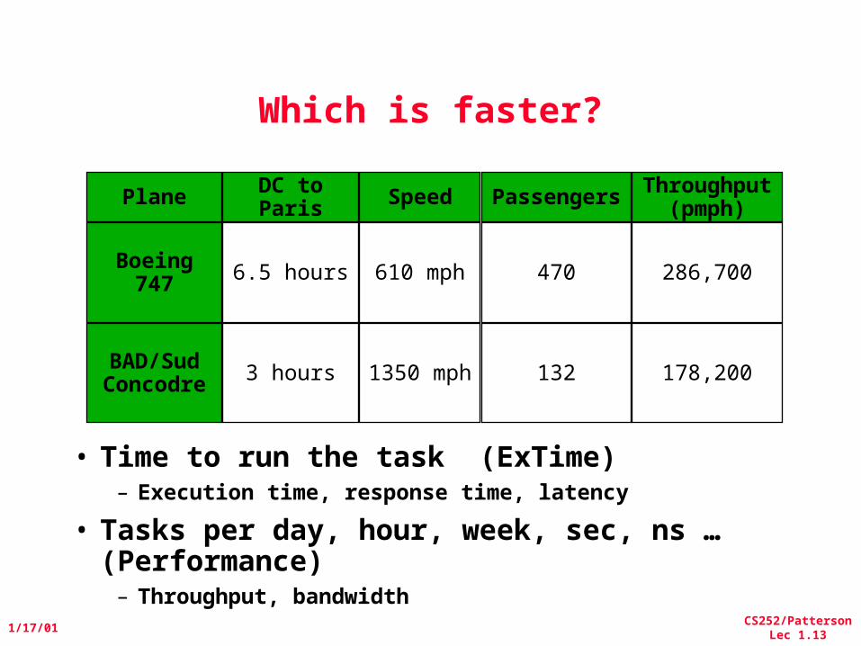
Which is faster?
• Time to run the task (ExTime)– Execution time, response time, latency
• Tasks per day, hour, week, sec, ns … (Performance)
– Throughput, bandwidth
Plane
Boeing 747
BAD/Sud Concodre
Speed
610 mph
1350 mph
DC to Paris
6.5 hours
3 hours
Passengers
470
132
Throughput (pmph)
286,700
178,200
CS252/PattersonLec 1.14
1/17/01
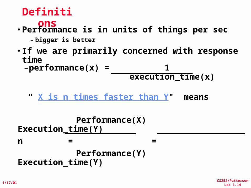
Performance(X) Execution_time(Y)
n = =
Performance(Y) Execution_time(Y)
Definitions
•Performance is in units of things per sec– bigger is better
•If we are primarily concerned with response time–performance(x) = 1
execution_time(x)
" X is n times faster than Y" means
CS252/PattersonLec 1.15
1/17/01
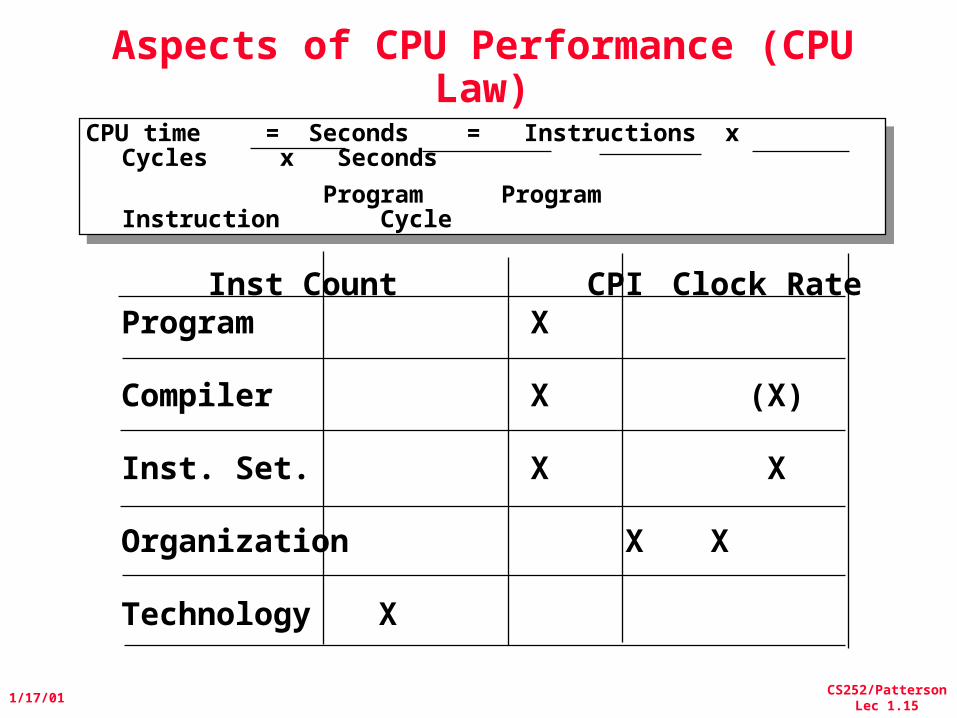
Aspects of CPU Performance (CPU Law)
CPU time = Seconds = Instructions x Cycles x Seconds
Program Program Instruction Cycle
CPU time = Seconds = Instructions x Cycles x Seconds
Program Program Instruction Cycle
Inst Count CPI Clock RateProgram X
Compiler X (X)
Inst. Set. X X
Organization X X
Technology X
CS252/PattersonLec 1.16
1/17/01
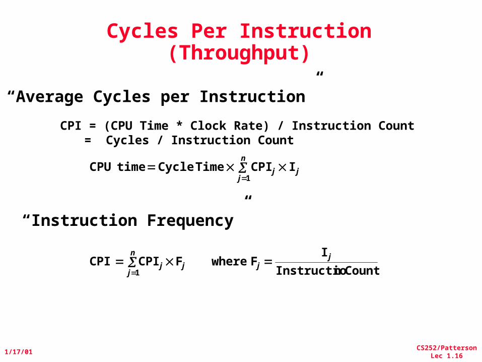
Cycles Per Instruction(Throughput)
“Instruction Frequency”
CPI = (CPU Time * Clock Rate) / Instruction Count = Cycles / Instruction Count
“Average Cycles per Instruction”
j
n
jj I CPI TimeCycle time CPU
1
Count nInstructio
I F where F CPI CPI j
j
n
jjj
1
CS252/PattersonLec 1.17
1/17/01
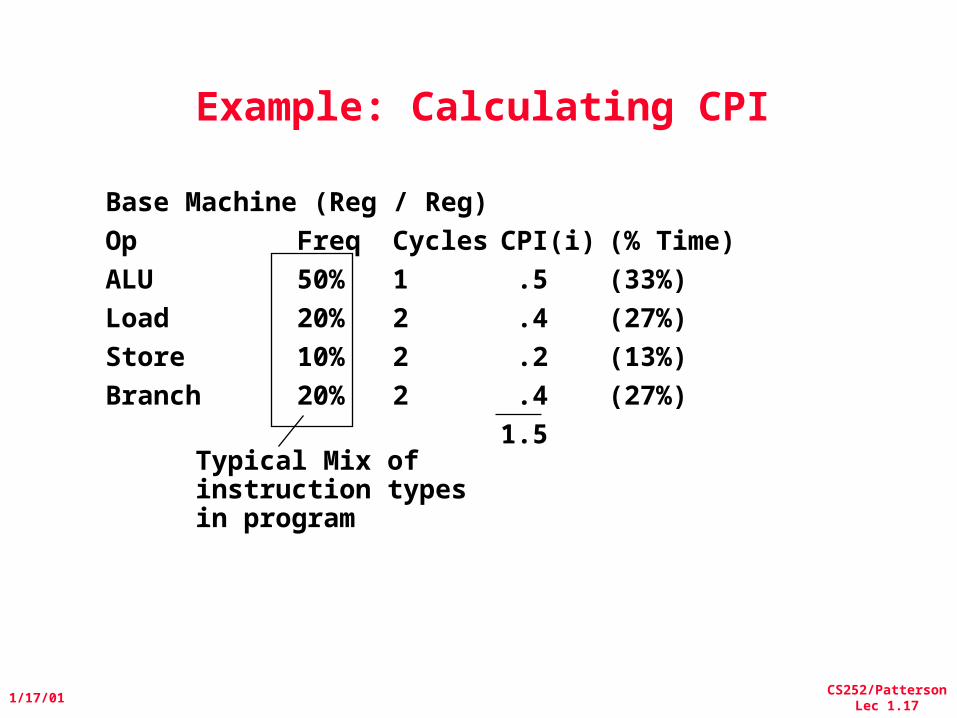
Example: Calculating CPI
Typical Mix of instruction typesin program
Base Machine (Reg / Reg)
Op Freq Cycles CPI(i) (% Time)
ALU 50% 1 .5 (33%)
Load 20% 2 .4 (27%)
Store 10% 2 .2 (13%)
Branch 20% 2 .4 (27%)
1.5
CS252/PattersonLec 1.18
1/17/01
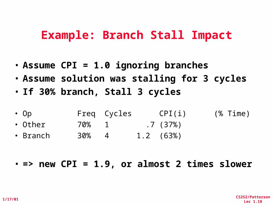
Example: Branch Stall Impact
• Assume CPI = 1.0 ignoring branches• Assume solution was stalling for 3 cycles• If 30% branch, Stall 3 cycles
• Op Freq Cycles CPI(i) (% Time)• Other 70% 1 .7 (37%)• Branch30% 4 1.2 (63%)
• => new CPI = 1.9, or almost 2 times slower
CS252/PattersonLec 1.19
1/17/01
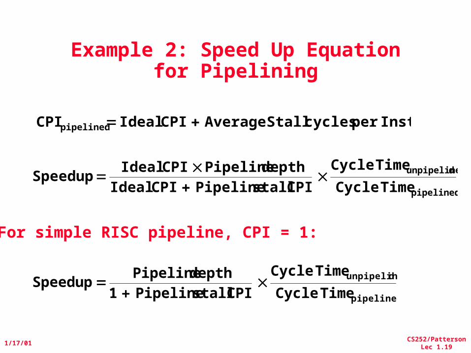
Example 2: Speed Up Equation for Pipelining
pipelined
dunpipeline
TimeCycle
TimeCycle
CPI stall Pipeline CPI Idealdepth Pipeline CPI Ideal
Speedup
pipelined
dunpipeline
TimeCycle
TimeCycle
CPI stall Pipeline 1depth Pipeline
Speedup
Instper cycles Stall Average CPI Ideal CPIpipelined
For simple RISC pipeline, CPI = 1:
CS252/PattersonLec 1.20
1/17/01
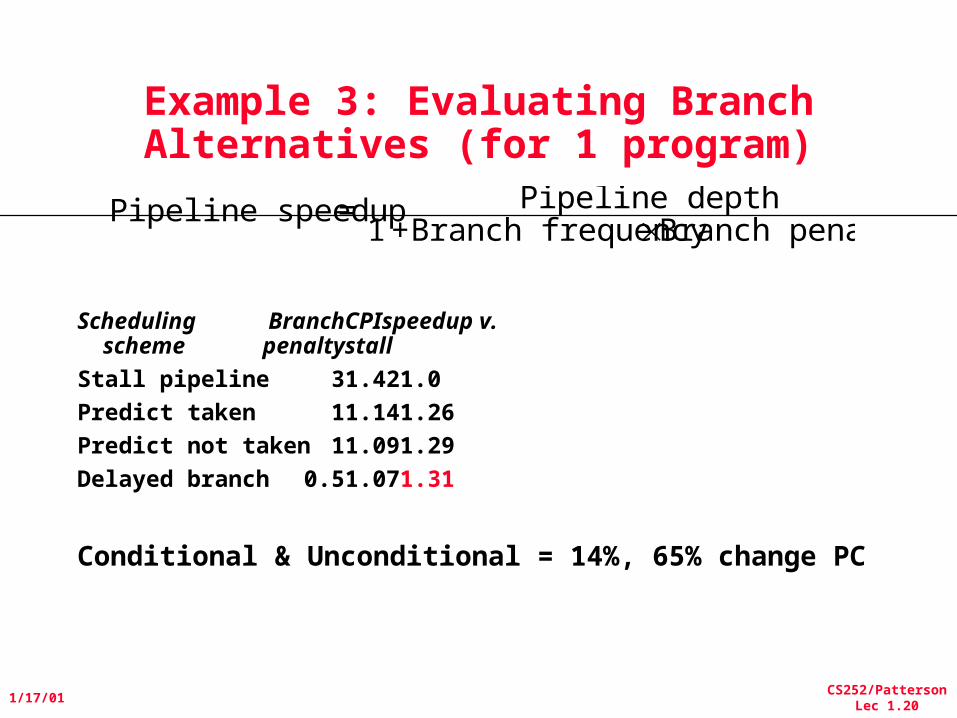
Example 3: Evaluating Branch Alternatives (for 1 program)
Scheduling Branch CPIspeedup v. scheme penalty stall
Stall pipeline 3 1.42 1.0
Predict taken 1 1.14 1.26
Predict not taken 1 1.09 1.29
Delayed branch 0.5 1.07 1.31
Conditional & Unconditional = 14%, 65% change PC
Pipeline speedup = Pipeline depth1 +Branch frequencyBranch penalty
CS252/PattersonLec 1.21
1/17/01
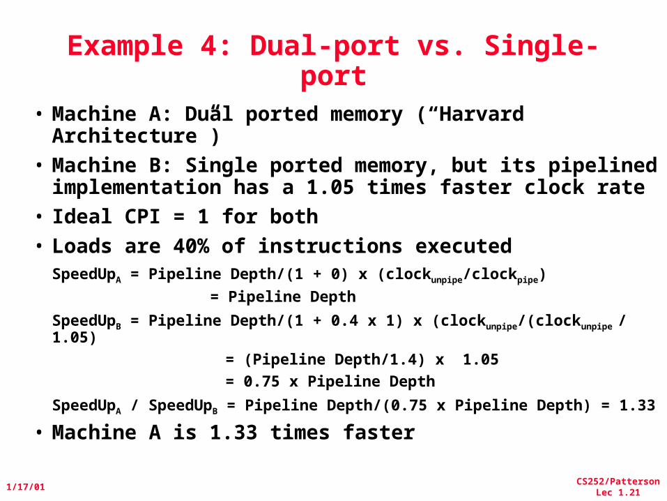
Example 4: Dual-port vs. Single-port
• Machine A: Dual ported memory (“Harvard Architecture”)
• Machine B: Single ported memory, but its pipelined implementation has a 1.05 times faster clock rate
• Ideal CPI = 1 for both• Loads are 40% of instructions executed
SpeedUpA = Pipeline Depth/(1 + 0) x (clockunpipe/clockpipe)
= Pipeline Depth
SpeedUpB = Pipeline Depth/(1 + 0.4 x 1) x (clockunpipe/(clockunpipe / 1.05)
= (Pipeline Depth/1.4) x 1.05
= 0.75 x Pipeline Depth
SpeedUpA / SpeedUpB = Pipeline Depth/(0.75 x Pipeline Depth) = 1.33
• Machine A is 1.33 times faster