Embed Size (px)
Citation preview
THE PRODUCTIVITY DEVICES
COMPANY
Hydraulic Clamping Fundamentals Rev - D 1 of 40
FUNDAMENTAL
TECHNICAL HYDRAULIC
CLAMPING INFORMATION
This is an uncontrolled document provided
for informative purposes only. Product
information contained herein is subject to
change without notification from Vektek.
Please refer to the Vektek Website, latest
VektorFlo® catalog or parts list for current
specifications.
Aug 2009
Rev D
THE PRODUCTIVITY DEVICES
COMPANY
Hydraulic Clamping Fundamentals Rev - D 2 of 40
Index Description Page Section I Hydraulic Systems & Circuits 3
• Why Hydraulics? And General Description
• Power Supplies
• Valves
• System Types
• Accumulators
• Orifices
• Filtration, Flow Requirements, Line Sizing
• Circuit Design and General Design Guides
• Sample Circuits
• Bleeding Air From System
Section II Work Supports 20 • General Description
• Sizing Work Supports and General Description
• Application information and Hydraulic Circuits
Section III Swing Clamps 25 • General Description
• General Information
• Positioning Time and Sizing
• Precautions, Hydraulic Fluid Compatibility
• Application Recommendations
Section IV Cylinders 33 • General Description and information
• Sizing
• Precautions
• Application Recommendations
Section V Position Sensing 38 • General Information, Air Logic
• Air Pressure Sensing
• Proximity Sensing. Mechanical Switches
• Magnetic Proximity Switch Sensing
THE PRODUCTIVITY DEVICES
COMPANY
Hydraulic Clamping Fundamentals Rev - D 3 of 40
SECTION I HYDRAULIC SYSTEMS & CIRCUITS
devices. For the purpose of discussion in this WHY HYDRAULICS?
Hydraulic actuators provide a consistent,
repeatable force in a relatively small weight and
size envelope. This means that in today’s
manufacturing environment, the work piece can
be secured, in less time, with more accuracy and
repeatability without sacrificing valuable fixture
space. This is especially true in systems that
operate above 2500 psi, to take an advantage of
the increased force generated from a smaller
component operating at higher pressure.
Hydraulic power clamping also provides the
manufacturer with flexibility in holding forces
and actuator functions to optimize the design for
machine operations as well as process
functionality (loading/unloading).
GENERAL DESCRIPTIONS
Hydraulics is a science that deals with the laws
governing liquids in motion. Specifically
addressed in this document is the use of liquid
hydraulic oil in motion and at rest in a system to
transmit or generate force for hydraulic
clamping applications.
Circuit is the routing and control of a confined
liquid to apply power. This power is used to
achieve a specific function resulting in work
being performed. For the discussions in this
document, the term circuit shall be intended to
indicate the planned functional components
(sort of like a document outline) as represented
in a schematic drawing.
System is often synonymous with a circuit, but
for discussion, should be additionally defined as
the components as they are physically
implemented into a working application or
circuit. This will include the actuators, fittings,
manifolds, hose and tubing routing and length of
run, as well as mounting styles of various
document, the term system shall indicate all of
the hydraulic components (sort of like a finished
printed document) of an installation as
physically implemented, or planned.
Force can be described as the amount of push or
pull between two objects. In power clamping
applications in the U.S., this force is typically
designated as pounds (lbs) and is achieved by
applying pressure to an actuator.
Pressure is the resistance to flow of a liquid,
and is in part responsible for creating the force
in a hydraulic system. In power clamping
applications, it is designated as pounds per
square inch (psi).
As water runs out of an unrestricted hose, it
flows at zero pressure (no resistance, ignoring
line losses). When you place your hand in front
of this hose, you will feel the force of the water.
This force is derived from pressure created by
the resistance of your hand to the flow. As you
move your hand closer to the end of the hose,
the resistance increases, as does the pressure,
which results in an increased force on your
hand.
Actuator is a device that uses the hydraulic
pressure to achieve mechanical movement, or
perform work. In work holding, this is
generally in the form of an applied force.
Actuators are typically broken down into two
different types, linear and rotary. For power
clamping applications, the primary focus is on
linear actuators.
Fluid Velocity is the average speed of the fluid
flowing past a given point in a specified amount
of time. In power clamping applications,
velocity is typically designated as feet per
second (fps).
Flow Rate is the measurement of a volume of
fluid flowing past a given point in a specific
THE PRODUCTIVITY DEVICES
COMPANY
Hydraulic Clamping Fundamentals Rev - D 4 of 40
amount of time. In power clamping
applications, flow rate is commonly designated
as either gallons per minute (gpm) or cubic
inches per minute (cim)
Valve is a device that directs the flow, or
operating condition of circuit. Some of the
valve types often found in power clamping is;
directional control, sequence, check, pressure
reducing, pressure limiting, shut off, and flow
control.
Orifice is a restriction in a hydraulic line or
component to help reduce the flow rate, or
create a pressure differential (inlet pressure
minus the outlet pressure)
Back Pressure is the resistance to flow
generated by the devices and the piping in a
hydraulic system. This is most often of concern,
but not limited to, systems using single acting
(spring returned) devices, as it will effect the
spring’s ability to push the hydraulic fluid from
an actuator back thru the system, allowing the
them to return to their relaxed state.
Hydraulic Pump is a device used to create
flow of a liquid in a hydraulic circuit. The
ability of a pump to produce flow against a
resistance is directly related to its’ available
input power. It may be driven by electrically,
pneumatically, hydraulically, or even manually.
HYDRAULIC POWER SUPPLIES
A hydraulic power supply is an assembly
consisting of a pump that has been configured in
such a way as to have the majority, if not all of
the ancillary components necessary to power
and control a pump as a pre-configured package.
In an effort to simplify implementation of a
hydraulic clamping system, the VektorFlo®
product line offers a variety of pre-configured
power supplies that have been designed to
provide optimum functionality for most power
clamping applications. Please refer to your
VektorFlo® catalog for specific details about
our power supply offerings and specifications.
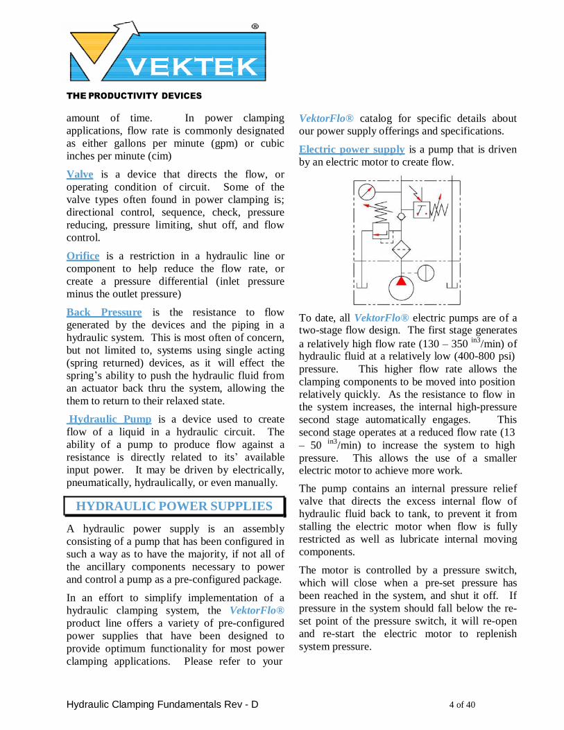
Electric power supply is a pump that is driven
by an electric motor to create flow.
To date, all VektorFlo® electric pumps are of a two-stage flow design. The first stage generates
a relatively high flow rate (130 – 350 in3
/min) of hydraulic fluid at a relatively low (400-800 psi)
pressure. This higher flow rate allows the
clamping components to be moved into position
relatively quickly. As the resistance to flow in the system increases, the internal high-pressure
second stage automatically engages. This
second stage operates at a reduced flow rate (13
– 50 in3
/min) to increase the system to high
pressure. This allows the use of a smaller electric motor to achieve more work.
The pump contains an internal pressure relief
valve that directs the excess internal flow of
hydraulic fluid back to tank, to prevent it from
stalling the electric motor when flow is fully
restricted as well as lubricate internal moving
components.
The motor is controlled by a pressure switch,
which will close when a pre-set pressure has
been reached in the system, and shut it off. If
pressure in the system should fall below the re-
set point of the pressure switch, it will re-open
and re-start the electric motor to replenish
system pressure.
THE PRODUCTIVITY DEVICES
COMPANY
Hydraulic Clamping Fundamentals Rev - D 5 of 40
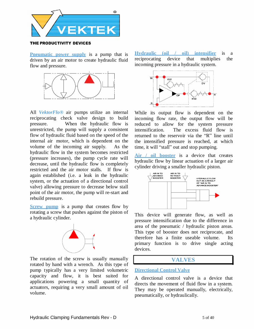
Pneumatic power supply is a pump that is
driven by an air motor to create hydraulic fluid
flow and pressure.
All VektorFlo® air pumps utilize an internal
reciprocating check valve design to build
pressure. When the hydraulic flow is
unrestricted, the pump will supply a consistent
flow of hydraulic fluid based on the speed of the
internal air motor, which is dependent on the
volume of the incoming air supply. As the
hydraulic flow in the system becomes restricted
(pressure increases), the pump cycle rate will
decrease, until the hydraulic flow is completely
restricted and the air motor stalls. If flow is
again established (i.e. a leak in the hydraulic
system, or the actuation of a directional control
valve) allowing pressure to decrease below stall
point of the air motor, the pump will re-start and
rebuild pressure.
Screw pump is a pump that creates flow by rotating a screw that pushes against the piston of
a hydraulic cylinder.
The rotation of the screw is usually manually
rotated by hand with a wrench. As this type of
pump typically has a very limited volumetric
capacity and flow, it is best suited for
applications powering a small quantity of
actuators, requiring a very small amount of oil
volume.
Hydraulic (oil / oil) intensifier is a reciprocating device that multiplies the
incoming pressure in a hydraulic system.
While its output flow is dependent on the
incoming flow rate, the output flow will be
reduced to allow for the system pressure
intensification. The excess fluid flow is
returned to the reservoir via the “R” line until
the intensified pressure is reached, at which
time, it will “stall” out and stop pumping.
Air / oil booster is a device that creates hydraulic flow by linear actuation of a larger air
cylinder driving a smaller hydraulic piston.
This device will generate flow, as well as
pressure intensification due to the difference in
area of the pneumatic / hydraulic piston areas.
This type of booster does not reciprocate, and
therefore has a finite useable volume. Its
primary function is to drive single acting
devices.
VALVES
Directional Control Valve
A directional control valve is a device that
directs the movement of fluid flow in a system.
They may be operated manually, electrically,
pneumatically, or hydraulically.
THE PRODUCTIVITY DEVICES
COMPANY
Hydraulic Clamping Fundamentals Rev - D 6 of 40
One of the most common directional control
valve designs is a type called a spool valve. By
nature of the design itself, spool valves can leak
across their various internal paths, which may
create problems with backpressure in your
system, heating of the oil in the pump’s
reservoir, as well as a clamp’s holding ability.
Vektek does not recommend using spool valves
in clamping systems and offers manual and
electrical control valves in either a poppet or a
shear seal style design.
The most common valve configurations used in
our industry are,
• Two position Three Way
• Three Position Four Way
Two-position three-way valve has two
different valve operator positions, open or
closed. It is described as a three-way valve
because there are three separate fluid flow paths,
or ports. These paths or ports are commonly
referred to as “P”, “T”, and “A”. “P” refers to
the pressure port as supplied from the pump
unit, “T” is the tank or return line to the pump
reservoir, and “A” is the working branch of the
circuit which is typically connected to the
clamp, or actuator. This type of value directs
flow in one direction at a time, from the pump
(“P”) to the actuator (“A”) in one position or
from the actuator (“A”) to the tank (“T”) in the
other position. Vektek recommends this style of
valve to control single acting devices.
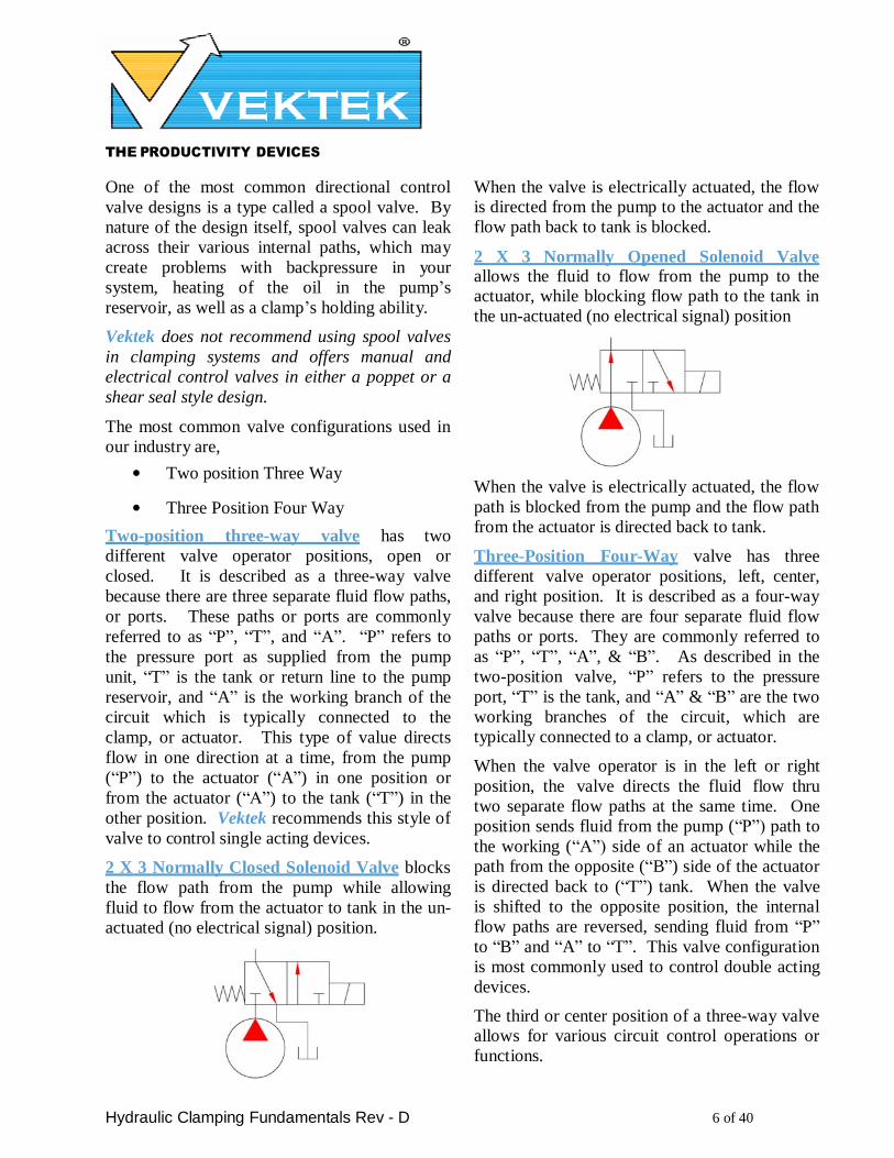
2 X 3 Normally Closed Solenoid Valve blocks
the flow path from the pump while allowing
fluid to flow from the actuator to tank in the un-
actuated (no electrical signal) position.
When the valve is electrically actuated, the flow is directed from the pump to the actuator and the
flow path back to tank is blocked.
2 X 3 Normally Opened Solenoid Valve allows the fluid to flow from the pump to the actuator, while blocking flow path to the tank in
the un-actuated (no electrical signal) position
When the valve is electrically actuated, the flow
path is blocked from the pump and the flow path
from the actuator is directed back to tank.
Three-Position Four-Way valve has three
different valve operator positions, left, center,
and right position. It is described as a four-way
valve because there are four separate fluid flow
paths or ports. They are commonly referred to
as “P”, “T”, “A”, & “B”. As described in the
two-position valve, “P” refers to the pressure
port, “T” is the tank, and “A” & “B” are the two
working branches of the circuit, which are
typically connected to a clamp, or actuator.
When the valve operator is in the left or right
position, the valve directs the fluid flow thru
two separate flow paths at the same time. One
position sends fluid from the pump (“P”) path to
the working (“A”) side of an actuator while the
path from the opposite (“B”) side of the actuator
is directed back to (“T”) tank. When the valve
is shifted to the opposite position, the internal
flow paths are reversed, sending fluid from “P”
to “B” and “A” to “T”. This valve configuration
is most commonly used to control double acting
devices.
The third or center position of a three-way valve allows for various circuit control operations or
functions.
THE PRODUCTIVITY DEVICES
COMPANY
Hydraulic Clamping Fundamentals Rev - D 7 of 40
Vektek currently offers three-position valves with two different center positions, “Closed
Center” and “P Blocked”:
3 X 4 “Closed” Center Valve blocks all
internal fluid paths (“P”, “T”, “A”, &”B”) so
that no flow is permitted from either the pump
or the actuator when in the center position.
The solenoid version of this configuration has a
mechanical spring to return the operator to the
center position when there is no electrical
signal.
3 X 4 “P” Blocked Center Valve blocks the
fluid path from the pump (“P”), but allows flow
from both sides of the actuator (“A” & “B”) to
return to tank (“T”) when in the center position.
The solenoid version of this configuration has a
mechanical spring to return the operator to the
center position when there is no electrical
signal.
Special Function Valves
Check Valve is a device that will allow flow
thru the valve in one direction only.
When the inlet flow is stopped the valve will
close and block the passage preventing the
return, or backward flow of fluid. This type of
valve requires a separate control valve, path, or
device to release the downstream fluid blocked
by the valve.
Pilot Operated Check Valve is a valve that
combines the function of a check valve as well
as an internal pilot piston to unseat the check
valve.
When pressure is applied to the pilot port, it will
open or “unseat” the check valve, allowing
return flow thru the valve. The pilot operated
valve is commonly used as an “A” or “A-B”
check valve to provide various control of the
flow in the actuator circuit.
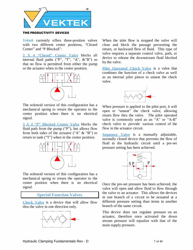
Sequence Valve is a manually adjustable,
normally closed device that prevents the flow of
fluid in the hydraulic circuit until a pre-set
pressure setting has been achieved.
Once the pre-set pressure has been achieved, the
valve will open and allow fluid to flow through
the valve to an actuator. This allows the devices
in one branch of a circuit to be actuated at a
different pressure setting than items in another
branch of the same circuit.
This device does not regulate pressure on an
actuator, therefore once activated the down
stream pressure will equalize with that of the
main supply pressure.
THE PRODUCTIVITY DEVICES
COMPANY
Hydraulic Clamping Fundamentals Rev - D 8 of 40
The amount of time required to open the valve is dependent upon the flow rate of the pump and
backpressure in the system.
When the inlet supply pressure is decreased
below the pre-set pressure, the valve will close
again and an internal check valve will open
permitting fluid flow from the actuator back
thru the valve. This will allow the sequenced
devices to return to pre-actuation condition.
Pressure Limiting Valve (PLV) is a manually
adjustable normally open valve that limits the
pressure in a branch of the circuit and will
maintain a lower pressure on that branch than
the main circuit pressure.
It will allow flow to pass from the inlet port thru
the valve to the outlet port and build pressure in
the downstream system. As the pressure in the
downstream system increases, backpressure thru
the valve causes it to close and block off flow.
The inlet pressure from the main system will
keep the flow blocked, and therefore cannot re-
open to compensate for pressure loss in the
downstream pressure limited system. When the
inlet pressure is removed, the valve will re-open
and allow the down stream fluid to return to
tank thru the valve. As this valve, by itself is
held closed by the main system pressure. It is
best suited for use with single acting actuators.
Contact your VekTorFlo® sales team for
information and recommendations when
installed in a double acting system.
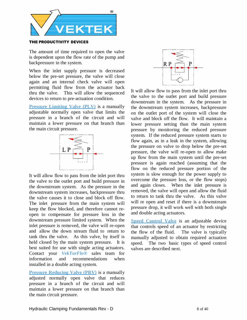
Pressure Reducing Valve (PRV) is a manually
adjusted normally open valve that reduces
pressure in a branch of the circuit and will
maintain a lower pressure on that branch than
the main circuit pressure.
It will allow flow to pass from the inlet port thru
the valve to the outlet port and build pressure
downstream in the system. As the pressure in
the downstream system increases, backpressure
on the outlet port of the system will close the
valve and block off the flow. It will maintain a
lower pressure setting than the main system
pressure by monitoring the reduced pressure
system. If the reduced pressure system starts to
flow again, as in a leak in the system, allowing
the pressure on valve to drop below the pre-set
pressure, the valve will re-open to allow make
up flow from the main system until the pre-set
pressure is again reached (assuming that the
flow on the reduced pressure portion of the
system is slow enough for the power supply to
overcome the pressure loss, or the flow stops)
and again closes. When the inlet pressure is
removed, the valve will open and allow the fluid
to return to tank thru the valve. As this valve
will re open and reset if there is a downstream
pressure drop, it will work well with both single
and double acting actuators.
Speed Control Valve is an adjustable device
that controls speed of an actuator by restricting
the flow of the fluid. The valve is typically
manually adjusted to obtain required actuation
speed. The two basic types of speed control
valves are described next.
THE PRODUCTIVITY DEVICES
COMPANY
Hydraulic Clamping Fundamentals Rev - D 9 of 40
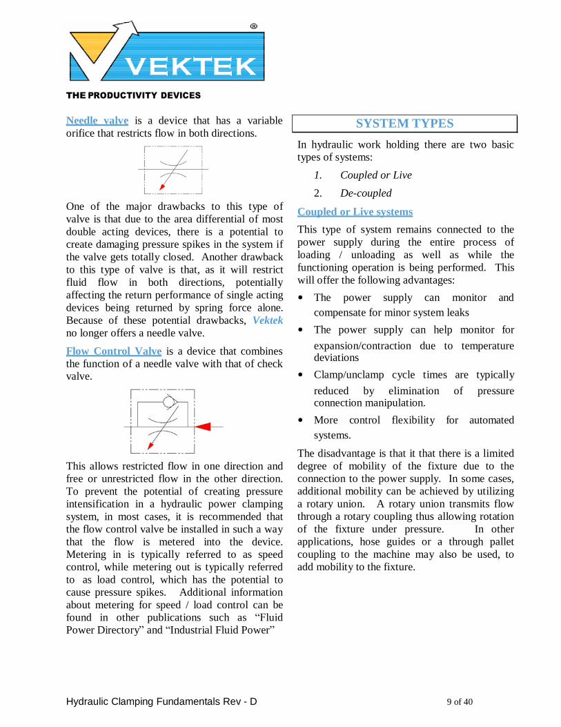
Needle valve is a device that has a variable
orifice that restricts flow in both directions.
One of the major drawbacks to this type of
valve is that due to the area differential of most
double acting devices, there is a potential to
create damaging pressure spikes in the system if
the valve gets totally closed. Another drawback
to this type of valve is that, as it will restrict
fluid flow in both directions, potentially
affecting the return performance of single acting
devices being returned by spring force alone.
Because of these potential drawbacks, Vektek
no longer offers a needle valve.
Flow Control Valve is a device that combines
the function of a needle valve with that of check valve.
This allows restricted flow in one direction and
free or unrestricted flow in the other direction.
To prevent the potential of creating pressure
intensification in a hydraulic power clamping
system, in most cases, it is recommended that
the flow control valve be installed in such a way
that the flow is metered into the device.
Metering in is typically referred to as speed
control, while metering out is typically referred
to as load control, which has the potential to
cause pressure spikes. Additional information
about metering for speed / load control can be
found in other publications such as “Fluid
Power Directory” and “Industrial Fluid Power”
SYSTEM TYPES
In hydraulic work holding there are two basic
types of systems:
1. Coupled or Live
2. De-coupled
Coupled or Live systems
This type of system remains connected to the
power supply during the entire process of
loading / unloading as well as while the
functioning operation is being performed. This
will offer the following advantages:
• The power supply can monitor and
compensate for minor system leaks
• The power supply can help monitor for
expansion/contraction due to temperature deviations
• Clamp/unclamp cycle times are typically
reduced by elimination of pressure connection manipulation.
• More control flexibility for automated
systems.
The disadvantage is that it that there is a limited
degree of mobility of the fixture due to the
connection to the power supply. In some cases,
additional mobility can be achieved by utilizing
a rotary union. A rotary union transmits flow
through a rotary coupling thus allowing rotation
of the fixture under pressure. In other
applications, hose guides or a through pallet
coupling to the machine may also be used, to
add mobility to the fixture.

THE PRODUCTIVITY DEVICES
COMPANY
Hydraulic Clamping Fundamentals Rev - D 10 of 40
De-Coupled Systems
This type of system is disconnected from the
power supply during machining operation.
Manual Shut-off Valve Decoupler
Automatic Shut-off Valve Decoupler
4 Sided Pallet Top Plate
The fluid transfer connection is made by using a
pallet de-coupler or tombstone top plate that
facilitates the connection and disconnection of
the power supply and the fixture. It has always
been Vektek’s policy that as a matter of safety
an accumulator is required in all de-coupled
systems. All VektorFlo®, pallet de-couplers
and top-plates are furnished with an
accumulator in the clamp system to help
maintain pressure, compensate for minor leaks,
as well as compensate for temperature / pressure
fluxuations.
A typical work holding circuit can contain a
mixture of both single and double acting
actuators. While coupled and de-coupled
systems can be used to control both single and
double acting actuators as well as combinations
of both, the VektorFlo® 2 sided and 4-sided
tombstone top plates will NOT work with
double acting devices.
The advantages of this type of system are:
• Maximum mobility of the fixture
• Staging of multiple fixtures on a machine line
The disadvantages are:
• Load/unload time may increased slightly because of the need to connect the hydraulic hoses
THE PRODUCTIVITY DEVICES
COMPANY
Hydraulic Clamping Fundamentals Rev - D 11 of 40
2
• Interface with automated
load/unload stations is more difficult
• Pressure loss from a leak in the system
may exceed of the accumulator’s capacity
• More susceptible to contamination into
the hydraulic system due to the repeated connection of the hydraulic supply hose(s).
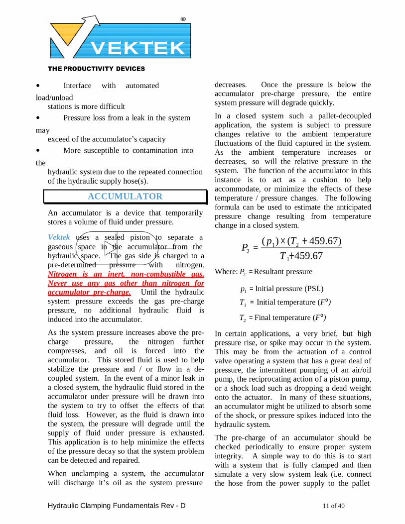
ACCUMULATOR
An accumulator is a device that temporarily
stores a volume of fluid under pressure.
decreases. Once the pressure is below the accumulator pre-charge pressure, the entire
system pressure will degrade quickly.
In a closed system such a pallet-decoupled
application, the system is subject to pressure
changes relative to the ambient temperature
fluctuations of the fluid captured in the system.
As the ambient temperature increases or
decreases, so will the relative pressure in the
system. The function of the accumulator in this
instance is to act as a cushion to help
accommodate, or minimize the effects of these
temperature / pressure changes. The following
formula can be used to estimate the anticipated
pressure change resulting from temperature
change in a closed system.
Vektek uses a sealed piston to separate a ( p ) × (T + 459.67) gaseous space in the accumulator from the
hydraulic space. The gas side is charged to a
pre-determined pressure with nitrogen.
Nitrogen is an inert, non-combustible gas.
Never use any gas other than nitrogen for
accumulator pre-charge. Until the hydraulic
system pressure exceeds the gas pre-charge
pressure, no additional hydraulic fluid is
induced into the accumulator.
As the system pressure increases above the pre-
charge pressure, the nitrogen further
compresses, and oil is forced into the
accumulator. This stored fluid is used to help
stabilize the pressure and / or flow in a de-
coupled system. In the event of a minor leak in
a closed system, the hydraulic fluid stored in the
accumulator under pressure will be drawn into
the system to try to offset the effects of that
fluid loss. However, as the fluid is drawn into
the system, the pressure will degrade until the
supply of fluid under pressure is exhausted.
This application is to help minimize the effects
of the pressure decay so that the system problem
can be detected and repaired.
When unclamping a system, the accumulator
will discharge it’s oil as the system pressure
P = 1 2
T 1+459.67
Where: P2 = Resultant pressure
p1 = Initial pressure (PSI.)
T1 = Initial temperature (F°)
T2 = Final temperature (F°)
In certain applications, a very brief, but high
pressure rise, or spike may occur in the system.
This may be from the actuation of a control
valve operating a system that has a great deal of
pressure, the intermittent pumping of an air/oil
pump, the reciprocating action of a piston pump,
or a shock load such as dropping a dead weight
onto the actuator. In many of these situations,
an accumulator might be utilized to absorb some
of the shock, or pressure spikes induced into the
hydraulic system.
The pre-charge of an accumulator should be
checked periodically to ensure proper system
integrity. A simple way to do this is to start
with a system that is fully clamped and then
simulate a very slow system leak (i.e. connect
the hose from the power supply to the pallet
THE PRODUCTIVITY DEVICES
COMPANY
Hydraulic Clamping Fundamentals Rev - D 12 of 40
decoupler and just slightly opening the handle
on a pallet decoupler allowing the hydraulic oil
to return to the pump’s reservoir). The gage in
the system will loose pressure very slowly, until
the accumulator pre-charge has been reached, at
which point the gage reading will fall to zero
almost instantaneously.
To achieve reliable performance from an
accumulator, the pre-charge of the gas on an
accumulator should be in the range of 20% to
75% of maximum hydraulic pressure.
The following formula will estimate the oil
volume for an accumulator with the Nitrogen
stabilized.
often considered constant because the
displacement is so small, and the differential
pressure changes so rapidly. While the
methodology for calculating flow through an
orifice can be tedious, it is well documented in
various technical manuals, and will not be
elaborated on here. However, because of the
nature of clamping systems, to obtain the
desired results for an individual system, it is
usually preferable to establish orifice sizing by
testing in your specific system.
• An orifice restricts flow in both directions
and therefore could possibly inhibit their return performance of single acting devices, due to an increase in back pressure.
v2 = V1 − ( ( P
1 ) ∗ (V )
1 ) ( P2 )
• The orifice is prone to plugging from system
contamination. Additional filtration maybe required to proved acceptable performance.
Where: v2 =Hyd. fluid volume. • Pressure drop is highly dependent on fluid
P1 = Accumulator pre-charge (PSI)
P2 =Max. hyd. system pres (PSI)
V 1 =Accumulator volume.
(For VektorFlo®, accumulator 10-1016-XX the
oil capacityV1 is 3.4 cubic inches and for 10-
1014-XX it is 1.2 cubic inches.)
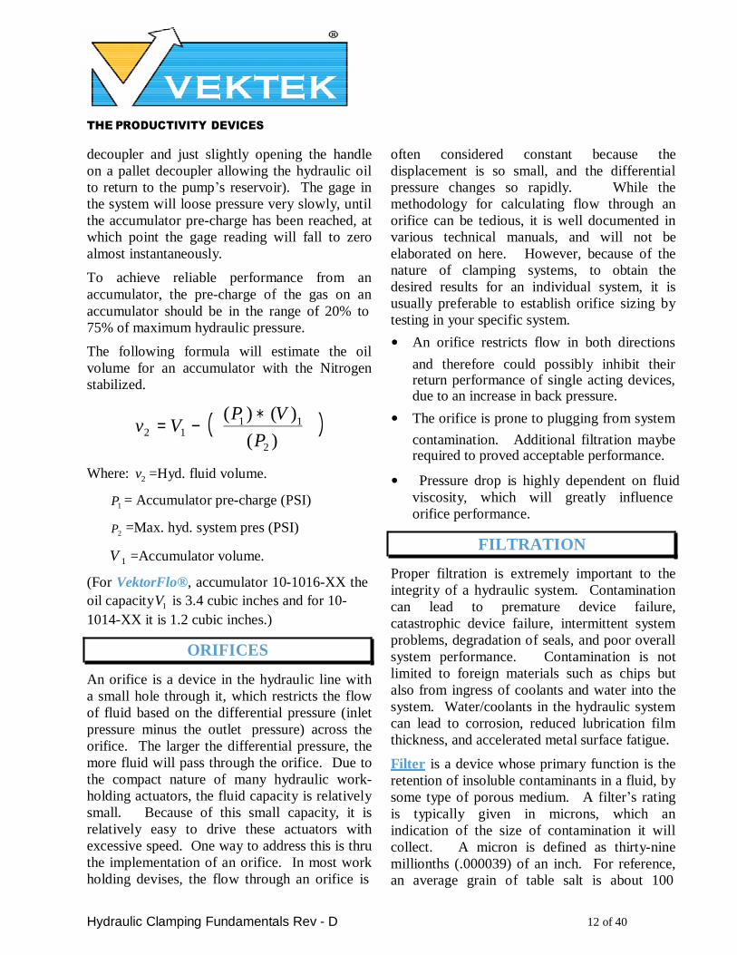
ORIFICES
An orifice is a device in the hydraulic line with
a small hole through it, which restricts the flow
of fluid based on the differential pressure (inlet
pressure minus the outlet pressure) across the
orifice. The larger the differential pressure, the
more fluid will pass through the orifice. Due to
the compact nature of many hydraulic work-
holding actuators, the fluid capacity is relatively
small. Because of this small capacity, it is
relatively easy to drive these actuators with
excessive speed. One way to address this is thru
the implementation of an orifice. In most work
holding devises, the flow through an orifice is
viscosity, which will greatly influence
orifice performance.
FILTRATION
Proper filtration is extremely important to the
integrity of a hydraulic system. Contamination
can lead to premature device failure,
catastrophic device failure, intermittent system
problems, degradation of seals, and poor overall
system performance. Contamination is not
limited to foreign materials such as chips but
also from ingress of coolants and water into the
system. Water/coolants in the hydraulic system
can lead to corrosion, reduced lubrication film
thickness, and accelerated metal surface fatigue.
Filter is a device whose primary function is the
retention of insoluble contaminants in a fluid, by
some type of porous medium. A filter’s rating
is typically given in microns, which an
indication of the size of contamination it will
collect. A micron is defined as thirty-nine
millionths (.000039) of an inch. For reference,
an average grain of table salt is about 100
THE PRODUCTIVITY DEVICES
COMPANY
Hydraulic Clamping Fundamentals Rev - D 13 of 40
microns in size; a human hair about 70, and
talcum powder is about 10. The most common
filtration recommendation for hydraulic
clamping system is 10 - 25 microns, which will
filter such things as grit, fines, and sludge.
However, to stop contaminants such as chips
from traveling in a system, a micron rating of up
to 180 (0.0070”) has proven adequate.
Screen (mesh) is a coarse strainer element that
stops larger contaminants from moving down
stream, but typically may not retain them.
LINE SIZING
It is recommended that the flow through the
lines be in the Laminar region. To keep flow in
the Laminar region requires a Reynolds number
of 2000 or less. Flows in 2000 to 4000 range
are Transitional, and above 4000 are Turbulent.
Transitional and Turbulent flows generate
higher back pressures and may interfere with
Sequence valve, PRV and PLV function,
therefore should be avoided when ever possible.
Screens are rated by U.S. Sieve No. instead of
microns. While these two ratings are not the
same, they can be compared as to the size of
N r = 3162 × Q
μ ×
d contaminates they will collect. For example,
(from the “Lightning Reference Handbook, 8th
Edition © Copyright 1990 published by Berendsen Fluid Power, Tulsa, Ok) a screen with a Sieve number of 50 has an approximate micron equivalent of 297 (0.0117” particulate); Sieve 140 is approximately 105 micron (0.0041” particulate); and Sieve 325 in
approximately 44 micron (0.0017” particulate). While a screen with a Sieve No. of 100 (0.0059”
particulate) should adequately stop chips and
debris from traveling in your system; the screen
should not be considered a replacement for a
primary filter element.
FLOW REQUIREMENT:
Where: Nr = Reynolds number
Q = Flow rate, GPM
μ =Viscosity in Centistokes,
132 for ISO 32 Hyd. fluid.
d = Inside diameter of line in
inches.
Velocity is the next consideration. For double
acting only systems, this can be as high as 33
FT/Sec. For systems containing single acting actuators, this should be limited to 10 FT/Sec.
V = .320833 × Q
A
Determine the time in seconds (T) allows for clamping. (Verify that this in the operating
ranges of the devices)
Pick the devices required for fixturing
application. Determine displacement in cubic
inches for each device. (Including volume of oil
in the accumulator and flex hose if applicable).
Add the displacement for the devices together
( D t ).
Where: A= cross sectional area =
d 2 ×.785
V=Velocity in Ft/Sec.
CIRCUIT DESIGN
Before the hydraulic circuit can be designed, the
following things must be defined:
• The type and number of each type of
hydraulic actuator to be used on fixture.
To determine required flow:
GPM = D
t × 60
T × 231
• The oil capacity of each actuator. (In cubic
inches) (231CIM = 1 GPM = 3.85 CIS)
THE PRODUCTIVITY DEVICES
COMPANY
Hydraulic Clamping Fundamentals Rev - D 14 of 40
• The operating pressures required.
See VektorFlo® catalog for pressure required for clamp force on each specific actuator.
• Required pressure reductions per circuit.
• The cycle time required to clamp
and unclamp.
• The sequence of operation.
• Type of control required.
• Coupled or de-coupled system.
GENERAL DESIGN GUIDES:
1. Unless otherwise noted in the catalog all
VektorFlo® components are rated for
5,000-psi maximum operating pressure. However, the system operating pressure is
determined by the lowest pressure rating of
a component in the system. It is important
when designing a circuit that all devices
including fittings, hoses, valves, tubing, and
manifolds have a working pressure
compatible with circuit pressure. Never
exceed the maximum operating pressure
of any device.
2. Fluid follows the course of least resistance,
so the device that has the fewest line restrictions will generally activate first.
3. Always flush hydraulic passages, tubing
lines, and hoses with a suitable safety
solvent to remove chips, dust, , dried
drawing oil, and other debris (i.e. spider
webs) before operating a system.
4. Avoid using sequence valves in series to
control operations. Erratic performance can
be expected due to valve pulsing. Since
sequence valves are pressure sensing,
plumbing them in parallel will not adversely
effect the system performance.
5. The recommended pressure differential
setting between all specialty valves is
500 psi. This is to allow enough
pressure
THE PRODUCTIVITY DEVICES
COMPANY
Hydraulic Clamping Fundamentals Rev - D 15 of 40
differential to observe expected results,
allow for variances between gage
accuracies, and some margin of error in
setting individual devices.
6. Sequence pressure setting should never be
below minimum required operating pressure of devices it is sequencing.
7. Avoid installing pressure limiting or
pressure reducing valves ahead of
directional control valves or sequence
valves.
8. Running single and double acting devices in
series (daisy chain) this will affect the return
time on single acting devices. Pay particular
attention to the plumbing installation in an
effort to minimize return flow backpressure.
9. Do not allow return flow to tank to pressurize another circuit.
10. When stacking multiple directional control
valves always use a check valve at each “P”
port (pressure inlet port) on valve to avoid
pressure drop in circuits already engaged
when additional circuits are energized.
11. Double acting devices should be used in
robotic systems wherever possible. This
will make return of actuators positive,
reducing probability of interference during
load, and unload operations, as well as
permit additional system monitoring.
12. Maximum velocity for high-pressure lines is
30 ft/sec. Maximum velocity for a return line is 10 ft/sec. It is recommended that
velocity for single acting systems be
maintained at a maximum equal to return
line velocity to reduce effect of
backpressure.
13. When considering required clamp time it is
important to keep in mind that some devices
have minimum actuation time requirements
in order to protect the integrity of individual
components. If the system flow requirement
THE PRODUCTIVITY DEVICES
COMPANY
Hydraulic Clamping Fundamentals Rev - D 16 of 40
for clamp time is established with in the
restrictions of the largest device, the
addition of a flow control will be required
to prevent over driving the smaller devices.
14. To provide smoother laminar fluid flow, use
a tubing bender and bend the tubing
whenever possible instead of using elbow
fittings.
15. Do not use flattened, wrinkled or kinked
tubing as this will have a negative effect on
flow as well as lead to premature failure of
the tubing.
16. Do not run tubing in a straight section from
one fitting to another, as this does not leave
any place for the flexure or expansion of the
tube. Provide an expansion loop or bend in
the tubing to compensate for changes in
temperature, vibration, and expansion.
17. In system designs always try to use as large
a line as feasible from power supply to
fixture in order to improve the response time
and help reduce the backpressure on single
acting devices.
18. Do not run hoses straight from port to port.
Allow the hose to loop or bend in order to
allow the hose to move or swell when
pressurized.
19. Do not exceed the manufactures' minimum bend radius on hoses, as rupture or kinking
will likely to occur.
20. When ever possible use a manifold as a
distribution point rather than “T” fittings.
This will reduce backpressure and improve
system response time.
21. When possible, avoid using equal force
opposing clamps as this will allow the work
piece to “float” between them. If this cannot
be avoided, a pilot operated check valve
must be installed in each line to prevent
plunger movement.
22. Do not use an intensifier after a pressure
reducing or a pressure-limiting valve.
23. Use a constant displacement pump on
intensified circuits. The use of a variable
displacement or a two-stage type pump can
attribute to erratic intensifier performance.
24. If using an intensifier in a decoupled system,
an accumulator needs to be installed
between the intensifier outlet and the rest of
the system.
25. Consideration should be given as to the
location of the power supply relative to the
location of the fixture. Every 5 feet of
vertical line run will increase system
backpressure on single acting devices by
approximately two (2) psi.
If using directional control valves mounted on a
decoupled pallet to control device actuation it is
recommended that a “T” port or return check be
in stalled on each valve in the circuit, This
check valve will prevent accidental actuation of
the system from another valve being switched or
from the leaking of another system to tank.
THE PRODUCTIVITY DEVICES
COMPANY
Hydraulic Clamping Fundamentals Rev - D 17 of 40
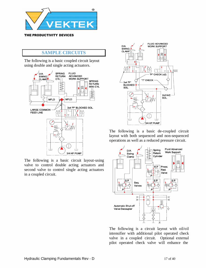
SAMPLE CIRCUITS
The following is a basic coupled circuit layout
using double and single acting actuators.
The following is a basic circuit layout-using
valve to control double acting actuators and
second valve to control single acting actuators
in a coupled circuit.
The following is a basic de-coupled circuit layout with both sequenced and non-sequenced
operations as well as a reduced pressure circuit.
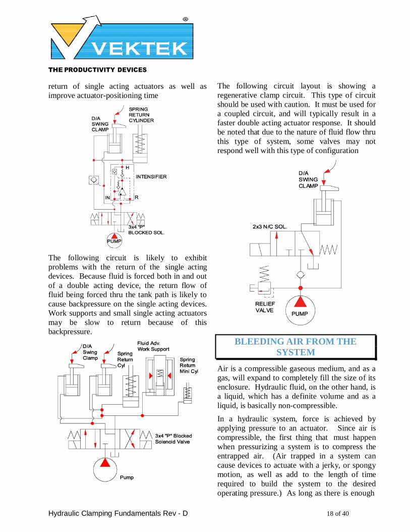
The following is a circuit layout with oil/oil
intensifier with additional pilot operated check
valve in a coupled circuit. Optional external
pilot operated check valve will enhance the
THE PRODUCTIVITY DEVICES
COMPANY
Hydraulic Clamping Fundamentals Rev - D 18 of 40
return of single acting actuators as well as
improve actuator-positioning time
The following circuit is likely to exhibit
problems with the return of the single acting
devices. Because fluid is forced both in and out
of a double acting device, the return flow of
fluid being forced thru the tank path is likely to
cause backpressure on the single acting devices.
Work supports and small single acting actuators
may be slow to return because of this
backpressure.
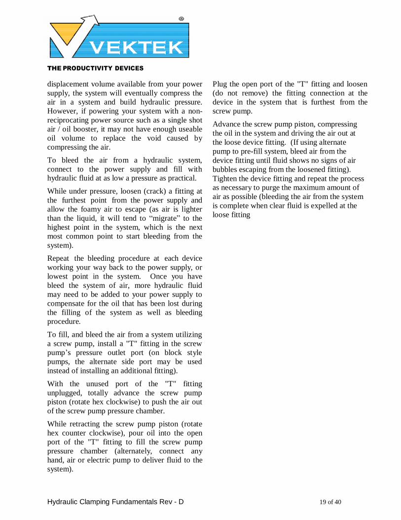
The following circuit layout is showing a
regenerative clamp circuit. This type of circuit
should be used with caution. It must be used for
a coupled circuit, and will typically result in a
faster double acting actuator response. It should
be noted that due to the nature of fluid flow thru
this type of system, some valves may not
respond well with this type of configuration
BLEEDING AIR FROM THE
SYSTEM
Air is a compressible gaseous medium, and as a
gas, will expand to completely fill the size of its
enclosure. Hydraulic fluid, on the other hand, is
a liquid, which has a definite volume and as a
liquid, is basically non-compressible.
In a hydraulic system, force is achieved by
applying pressure to an actuator. Since air is
compressible, the first thing that must happen
when pressurizing a system is to compress the
entrapped air. (Air trapped in a system can
cause devices to actuate with a jerky, or spongy
motion, as well as add to the length of time
required to build the system to the desired
operating pressure.) As long as there is enough
THE PRODUCTIVITY DEVICES
COMPANY
Hydraulic Clamping Fundamentals Rev - D 19 of 40
displacement volume available from your power
supply, the system will eventually compress the
air in a system and build hydraulic pressure.
However, if powering your system with a non-
reciprocating power source such as a single shot
air / oil booster, it may not have enough useable
oil volume to replace the void caused by
compressing the air.
To bleed the air from a hydraulic system,
connect to the power supply and fill with hydraulic fluid at as low a pressure as practical.
While under pressure, loosen (crack) a fitting at
the furthest point from the power supply and
allow the foamy air to escape (as air is lighter
than the liquid, it will tend to “migrate” to the
highest point in the system, which is the next
most common point to start bleeding from the
system).
Repeat the bleeding procedure at each device
working your way back to the power supply, or
lowest point in the system. Once you have
bleed the system of air, more hydraulic fluid
may need to be added to your power supply to
compensate for the oil that has been lost during
the filling of the system as well as bleeding
procedure.
To fill, and bleed the air from a system utilizing
a screw pump, install a "T" fitting in the screw
pump’s pressure outlet port (on block style
pumps, the alternate side port may be used
instead of installing an additional fitting).
With the unused port of the "T" fitting
unplugged, totally advance the screw pump
piston (rotate hex clockwise) to push the air out
of the screw pump pressure chamber.
While retracting the screw pump piston (rotate
hex counter clockwise), pour oil into the open
port of the "T" fitting to fill the screw pump
pressure chamber (alternately, connect any
hand, air or electric pump to deliver fluid to the
system).
Plug the open port of the "T" fitting and loosen
(do not remove) the fitting connection at the
device in the system that is furthest from the
screw pump.
Advance the screw pump piston, compressing
the oil in the system and driving the air out at
the loose device fitting. (If using alternate
pump to pre-fill system, bleed air from the
device fitting until fluid shows no signs of air
bubbles escaping from the loosened fitting).
Tighten the device fitting and repeat the process as necessary to purge the maximum amount of
air as possible (bleeding the air from the system
is complete when clear fluid is expelled at the
loose fitting
THE PRODUCTIVITY DEVICES
COMPANY
Hydraulic Clamping Fundamentals Rev - D 20 of 40
SECTION II WORK SUPPORTS
GENERAL DESCRIPTION
Work supports are supplementary support
devices to be used in conjunction with rigid
support and / or locating points in a fixture.
They also supports reduce the effects of
vibration and deflection, helping to maintain
work-piece accuracy during machining
operations.
The work support also helps compensate
automatically for minor part variations during
loading and imposed deflections during
clamping and machining operations.
Work supports use a hydraulically compressed sleeve to lock the plunger in place once it has
engaged the work-piece.
On the Fluid Advance and Spring Advance
work supports, the spring force on the plunger
determines the contact force on the work-piece.
In the case of the Air Advanced work support,
adjusting the air inlet pressure on the plunger
determines the contact force exerted against the
work piece.
TYPE AND FUNCTION
(See catalog for specific work support
dimensional, locating, and mounting data.)
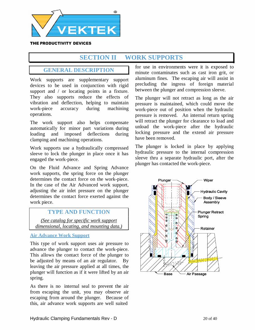
Air Advance Work Support
This type of work support uses air pressure to
advance the plunger to contact the work-piece.
This allows the contact force of the plunger to
be adjusted by means of an air regulator. By
leaving the air pressure applied at all times, the
plunger will function as if it were lifted by an air
spring.
As there is no internal seal to prevent the air
from escaping the unit, you may observe air
escaping from around the plunger. Because of
this, air advance work supports are well suited
for use in environments were it is exposed to
minute contaminates such as cast iron grit, or
aluminum fines. The escaping air will assist in
precluding the ingress of foreign material
between the plunger and compression sleeve.
The plunger will not retract as long as the air
pressure is maintained, which could move the
work-piece out of position when the hydraulic
pressure is removed. An internal return spring
will retract the plunger for clearance to load and
unload the work-piece after the hydraulic
locking pressure and the extend air pressure
have been removed.
The plunger is locked in place by applying
hydraulic pressure to the internal compression
sleeve thru a separate hydraulic port, after the
plunger has contacted the work-piece.
THE PRODUCTIVITY DEVICES
COMPANY
Hydraulic Clamping Fundamentals Rev - D 21 of 40
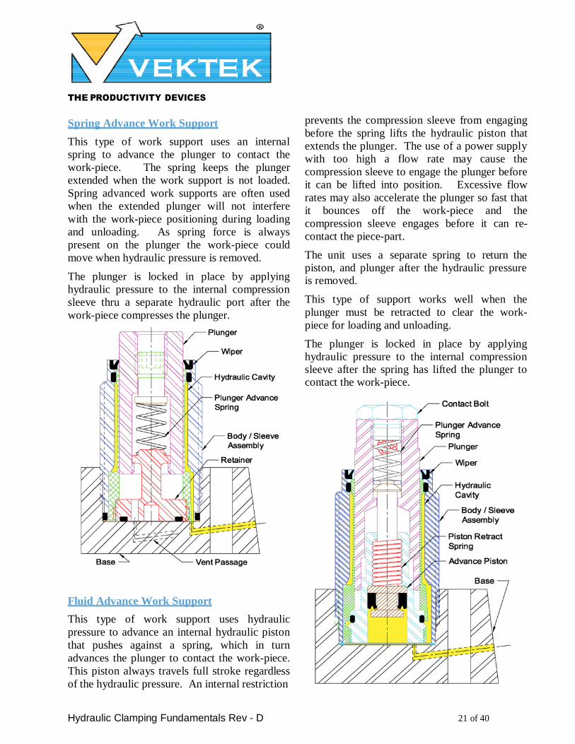
Spring Advance Work Support
This type of work support uses an internal
spring to advance the plunger to contact the
work-piece. The spring keeps the plunger
extended when the work support is not loaded.
Spring advanced work supports are often used
when the extended plunger will not interfere
with the work-piece positioning during loading
and unloading. As spring force is always
present on the plunger the work-piece could
move when hydraulic pressure is removed.
The plunger is locked in place by applying
hydraulic pressure to the internal compression
sleeve thru a separate hydraulic port after the
work-piece compresses the plunger.
Fluid Advance Work Support
This type of work support uses hydraulic
pressure to advance an internal hydraulic piston
that pushes against a spring, which in turn
advances the plunger to contact the work-piece.
This piston always travels full stroke regardless
of the hydraulic pressure. An internal restriction
prevents the compression sleeve from engaging
before the spring lifts the hydraulic piston that
extends the plunger. The use of a power supply
with too high a flow rate may cause the
compression sleeve to engage the plunger before
it can be lifted into position. Excessive flow
rates may also accelerate the plunger so fast that
it bounces off the work-piece and the
compression sleeve engages before it can re-
contact the piece-part.
The unit uses a separate spring to return the
piston, and plunger after the hydraulic pressure is removed.
This type of support works well when the
plunger must be retracted to clear the work-
piece for loading and unloading.
The plunger is locked in place by applying
hydraulic pressure to the internal compression sleeve after the spring has lifted the plunger to contact the work-piece.
THE PRODUCTIVITY DEVICES
COMPANY
Hydraulic Clamping Fundamentals Rev - D 22 of 40
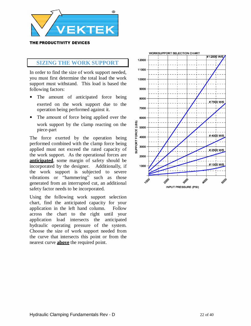
SIZING THE WORK SUPPORT
In order to find the size of work support needed,
you must first determine the total load the work
support must withstand. This load is based the
following factors:
• The amount of anticipated force being
exerted on the work support due to the operation being performed against it.
• The amount of force being applied over the
work support by the clamp reacting on the piece-part
The force exerted by the operation being
performed combined with the clamp force being
applied must not exceed the rated capacity of
the work support. As the operational forces are
anticipated, some margin of safety should be
incorporated by the designer. Additionally, if
the work support is subjected to severe
vibrations or “hammering” such as those
generated from an interrupted cut, an additional
safety factor needs to be incorporated.
Using the following work support selection
chart, find the anticipated capacity for your
application in the left hand column. Follow
across the chart to the right until your
application load intersects the anticipated
hydraulic operating pressure of the system.
Choose the size of work support needed from
the curve that intersects this point or from the
nearest curve above the required point.
THE PRODUCTIVITY DEVICES
COMPANY
Hydraulic Clamping Fundamentals Rev - D 23 of 40
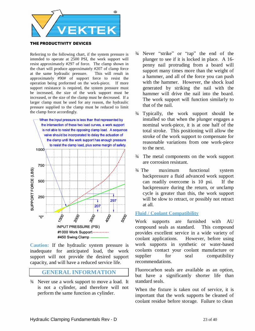
Referring to the following chart, if the system pressure is
intended to operate at 2500 PSI, the work support will
resist approximately #297 of force. The clamp shown in
the chart will produce approximately #207 of clamp force
at the same hydraulic pressure. This will result in
approximately #90# of support force to resist the
operation being preformed on the work-piece. If more
support resistance is required, the system pressure must
be increased, the size of the work support must be
increased, or the size of the clamp must be decreased. If a
larger clamp must be used for any reason, the hydraulic
pressure supplied to the clamp must be reduced to limit
the clamp force accordingly.
Caution: If the hydraulic system pressure is
inadequate for anticipated load, the work
support will not provide the desired support
capacity, and will have a reduced service life.
GENERAL INFORMATION
¾ Never use a work support to move a load. It
is not a cylinder, and therefore will not perform the same function as cylinder.
¾ Never “strike” or “rap” the end of the
plunger to see if it is locked in place. A 16-
penny nail protruding from a board will
support many times more than the weight of
a hammer, and all of the force you can push
with the hammer. However, the shock load
generated by striking the nail with the
hammer will drive the nail into the board.
The work support will function similarly to
that of the nail.
¾ Typically, the work support should be
installed so that when the plunger engages a
nominal work-piece, it is at one half of the
total stroke. This positioning will allow the
stroke of the work support to compensate for
reasonable variations from one work-piece
to the next.
¾ The metal components on the work support
are corrosion resistant.
¾ The maximum functional system
backpressure a fluid advanced work support
can readily overcome is 10 psi. If the
backpressure during the return, or unclamp
cycle is greater than this, the work support
will be slow to retract, or possibly not retract
at all.
Fluid / Coolant Compatibility
Work supports are furnished with AU
compound seals as standard. This compound
provides excellent service in a wide variety of
coolant applications. However, before using
work supports in synthetic or water-based
coolants contact your coolant manufacture or
supplier for seal compatibility
recommendations.
Fluorocarbon seals are available as an option, but have a significantly shorter life than
standard seals.
When the fixture is taken out of service, it is
important that the work supports be cleaned of
coolant residue before storage. Failure to clean

THE PRODUCTIVITY DEVICES
COMPANY
Hydraulic Clamping Fundamentals Rev - D 24 of 40
this residue may result in the work supports
sticking when returned to service.
The work supports are designed to function with
an ISO 32 grade hydraulic fluid. Contact your
fluid manufacture for seal compatibility
recommendations if use of a synthetic or water
based hydraulic fluid is intended.
APPLICATION INFORMATION
¾ Max. Hyd. Op. Pres. - 5,000 psi
¾ Min. Hyd. Op. Pres. - 750 psi
¾ Max. Op. Temp. - 160˚ F
¾ Min. Op. Temp. - 40˚ F
¾ Max. Flow Rate - 360 cu. in. per minute
¾ Hyd. Fluid Filtration - 25-micron
Application Recommendations
Work supports can be mounted in any position
relative to the work-piece, however for optimal
life and performance, the loading should be
axial to the work support. When ever possible,
avoid severe angular or offset loading
applications.
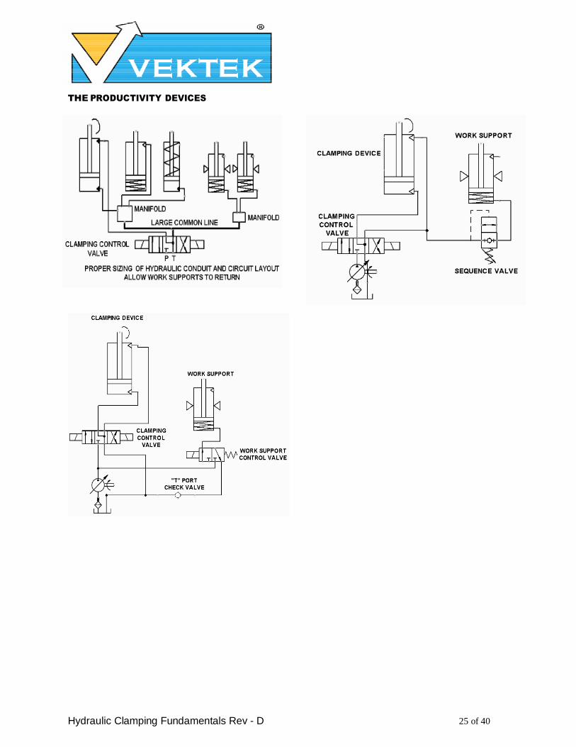
Hydraulic Circuits
For best performance, hydraulic circuits should
be designed so that the work supports are not
“daisy chained together” (or at least to a bare
minimum) and have adequate hydraulic fluid
passage size to prevent excessive backpressure.
When used in conjunction with other devices
the hydraulic fluid passages for work supports
should either be isolated from other devices or
sized so that return flow from these devices do
not prevent work supports from returning do to
induced backpressure.
Always provide enough timing or provide
proper sequencing to insure complete lock up of work support before loading. As an alternate to
this be sure the part is fully restrained before activating work support.
THE PRODUCTIVITY DEVICES
COMPANY
Hydraulic Clamping Fundamentals Rev - D 25 of 40
THE PRODUCTIVITY DEVICES
COMPANY
Hydraulic Clamping Fundamentals Rev - D 26 of 40
SECTION III SWING CLAMPS
GENERAL DESCRIPTION
Swing clamps are primary work holding devices
that are typically used to keep a work piece
stationary over locating points.
They provide axial clamping force proportional
to the hydraulic pressure applied. The clamp
arm will rise and rotate for ease of work piece
loading.
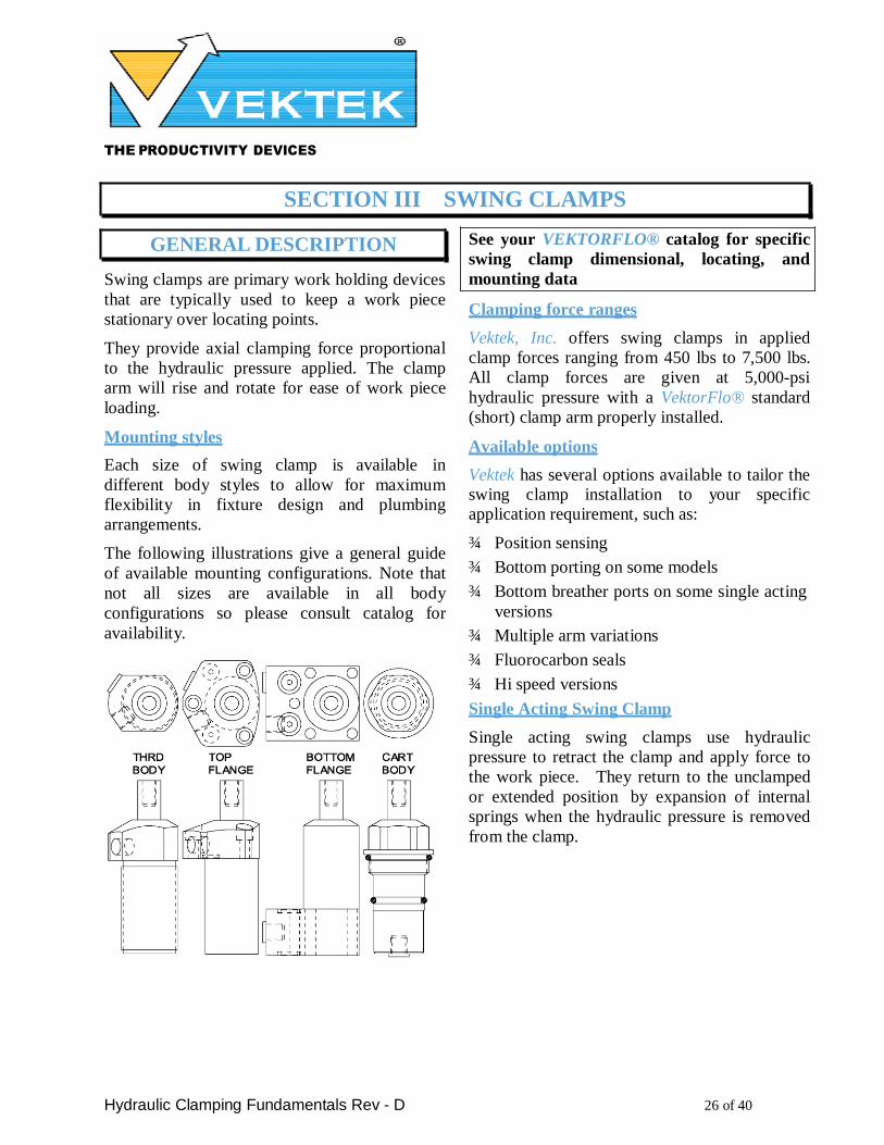
Mounting styles
Each size of swing clamp is available in
different body styles to allow for maximum
flexibility in fixture design and plumbing
arrangements.
The following illustrations give a general guide
of available mounting configurations. Note that
not all sizes are available in all body
configurations so please consult catalog for
availability.
See your VEKTORFLO® catalog for specific
swing clamp dimensional, locating, and
mounting data
Clamping force ranges
Vektek, Inc. offers swing clamps in applied
clamp forces ranging from 450 lbs to 7,500 lbs.
All clamp forces are given at 5,000-psi
hydraulic pressure with a VektorFlo® standard
(short) clamp arm properly installed.
Available options
Vektek has several options available to tailor the swing clamp installation to your specific application requirement, such as:
¾ Position sensing
¾ Bottom porting on some models
¾ Bottom breather ports on some single acting
versions
¾ Multiple arm variations
¾ Fluorocarbon seals
¾ Hi speed versions
Single Acting Swing Clamp
Single acting swing clamps use hydraulic
pressure to retract the clamp and apply force to
the work piece. They return to the unclamped
or extended position by expansion of internal
springs when the hydraulic pressure is removed
from the clamp.
THE PRODUCTIVITY DEVICES
COMPANY
Hydraulic Clamping Fundamentals Rev - D 27 of 40
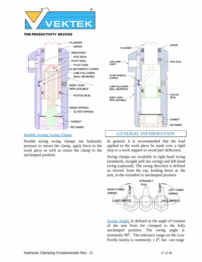
Double Acting Swing Clamp
Double acting swing clamps use hydraulic
pressure to retract the clamp, apply force to the
work piece as well as return the clamp to the
unclamped position.
GENERAL INFORMATION
In general, it is recommended that the load applied to the work piece be made over a rigid stop or a work support to avoid part deflection.
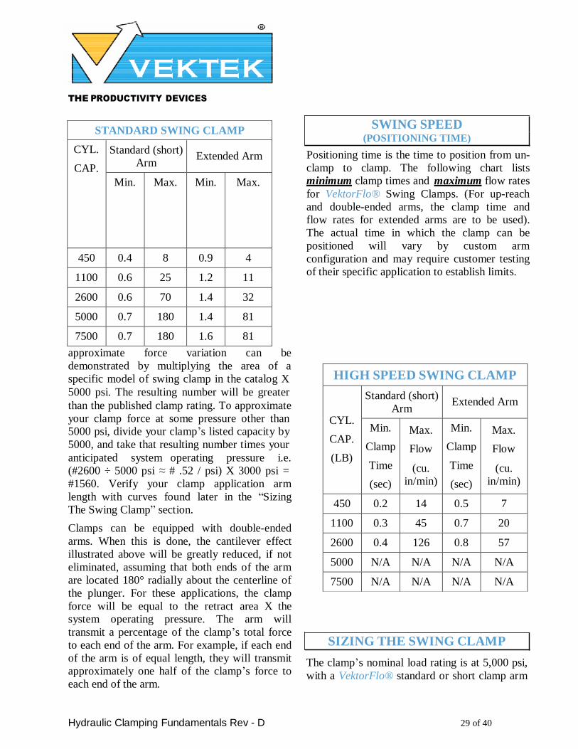
Swing clamps are available in right hand swing
(standard), straight pull (no swing) and left-hand
swing (optional). The swing direction is defined
as viewed from the top, looking down at the
arm, in the extended or unclamped position.
Swing Angle: Is defined as the angle of rotation
of the arm from the clamped to the fully
unclamped position. The swing angle is
nominally 90°. The tolerance range on the Low Profile family is commonly ± 4°, but can range
THE PRODUCTIVITY DEVICES
COMPANY
Hydraulic Clamping Fundamentals Rev - D 28 of 40
as high as ± 8° from one unit to the next. All
other families are ± 3°.
Repeatability: Is defined as the allowable angle
tolerance of the arm as it contacts the part, with
out any outside influence. Repeatability is
independent of swing angle and is ± 1½° on all families except High-Speed. Repeatability on the High-Speed swing clamp is ± ½°.
There may be instances in your application
when you do not want, or cannot tolerate clamps
rotating the full Swing Angle. Optional swing
restrictors are available that reduce the included
angle of the unclamp swing, which will reduce
the total/rotational stroke of the unit.
Typically, the swing clamp should be installed
so that when the arm engages a nominal work-
piece, it is at one half of the clamp stroke. This
will allow for compensation of work piece
dimensional variables.
The maximum functional system backpressure a
single acting swing clamp can readily overcome
is 10 psi. If the backpressure during the return,
or unclamp cycle is greater than this, the swing
clamp will be slow to extend (unclamp), or
possibly not extend at all.
In automated or robotic load and unload
applications, double acting clamps should be
used when ever possible. The hydraulic pressure
applied to the return, or unclamp side of the
piston (as opposed to a mechanical spring) will
help insure that the clamp arm is unclamped, or
“out of the way”. Double acting systems also
permit the use of devices such as pressure
switches in the unclamp line to convey feedback
information to a computer, or controller.
Large or custom arms may also require the use
of a double acting device to insure that the arm can be lifted, or unclamped.
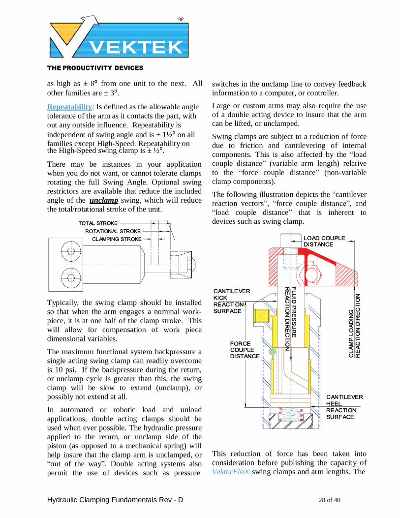
Swing clamps are subject to a reduction of force
due to friction and cantilevering of internal
components. This is also affected by the “load
couple distance” (variable arm length) relative
to the “force couple distance” (non-variable
clamp components).
The following illustration depicts the “cantilever
reaction vectors”, “force couple distance”, and
“load couple distance” that is inherent to
devices such as swing clamp.
This reduction of force has been taken into
consideration before publishing the capacity of
VektorFlo® swing clamps and arm lengths. The
THE PRODUCTIVITY DEVICES
COMPANY
Hydraulic Clamping Fundamentals Rev - D 29 of 40
STANDARD SWING CLAMP
CYL.
CAP.
Standard (short)
Arm
Extended Arm
Min. Max. Min. Max.
450 0.4 8 0.9 4
1100 0.6 25 1.2 11
2600 0.6 70 1.4 32
5000 0.7 180 1.4 81
7500 0.7 180 1.6 81
SWING SPEED (POSITIONING TIME)
Positioning time is the time to position from un-
clamp to clamp. The following chart lists
minimum clamp times and maximum flow rates
for VektorFlo® Swing Clamps. (For up-reach
and double-ended arms, the clamp time and
flow rates for extended arms are to be used).
The actual time in which the clamp can be
positioned will vary by custom arm
configuration and may require customer testing
of their specific application to establish limits.
approximate force variation can be
demonstrated by multiplying the area of a
specific model of swing clamp in the catalog X
5000 psi. The resulting number will be greater
than the published clamp rating. To approximate
your clamp force at some pressure other than
5000 psi, divide your clamp’s listed capacity by
5000, and take that resulting number times your
anticipated system operating pressure i.e.
(#2600 ÷ 5000 psi ≈ # .52 / psi) X 3000 psi =
#1560. Verify your clamp application arm
length with curves found later in the “Sizing
The Swing Clamp” section.
Clamps can be equipped with double-ended
arms. When this is done, the cantilever effect
illustrated above will be greatly reduced, if not
eliminated, assuming that both ends of the arm
are located 180° radially about the centerline of
the plunger. For these applications, the clamp
force will be equal to the retract area X the
system operating pressure. The arm will
transmit a percentage of the clamp’s total force
to each end of the arm. For example, if each end
of the arm is of equal length, they will transmit
approximately one half of the clamp’s force to
each end of the arm.
HIGH SPEED SWING CLAMP
CYL.
CAP.
(LB)
Standard (short)
Arm
Extended Arm
Min.
Clamp
Time
(sec)
Max.
Flow
(cu.
in/min)
Min.
Clamp
Time
(sec)
Max.
Flow
(cu.
in/min)
450 0.2 14 0.5 7
1100 0.3 45 0.7 20
2600 0.4 126 0.8 57
5000 N/A N/A N/A N/A
7500 N/A N/A N/A N/A
SIZING THE SWING CLAMP
The clamp’s nominal load rating is at 5,000 psi,
with a VektorFlo® standard or short clamp arm
THE PRODUCTIVITY DEVICES
COMPANY
Hydraulic Clamping Fundamentals Rev - D 30 of 40
properly attached. The clamping force being
applied is a function of:
• The length of the clamp arm from center
of clamp to point of contact on the work piece
• The hydraulic pressure applied to the clamp
• In order to find the size of swing clamp needed, you must first determine the total load the swing clamp must resist. This load is
based on the following factors:
• The anticipated force from the
operation being performed (as the work-piece retention forces are anticipated, some margin of safety should be incorporated)
• The direction of the force vectors as a
result of the operation being preformed
• The weight of the part may also be an
issue, depending on work piece orientation.
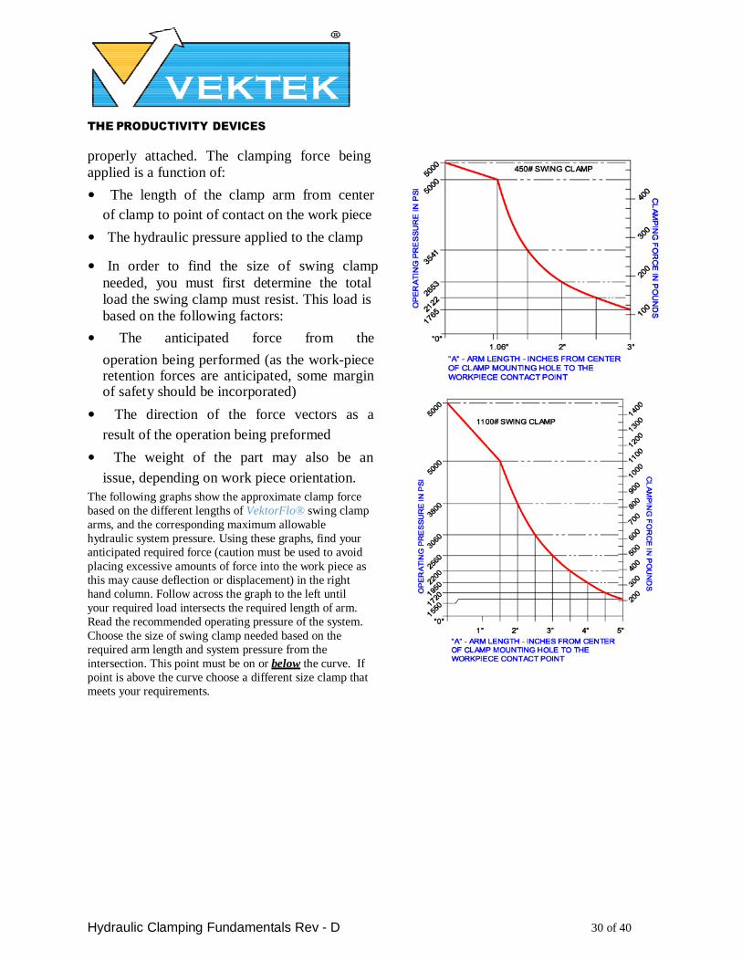
The following graphs show the approximate clamp force
based on the different lengths of VektorFlo® swing clamp
arms, and the corresponding maximum allowable
hydraulic system pressure. Using these graphs, find your
anticipated required force (caution must be used to avoid
placing excessive amounts of force into the work piece as
this may cause deflection or displacement) in the right
hand column. Follow across the graph to the left until
your required load intersects the required length of arm.
Read the recommended operating pressure of the system.
Choose the size of swing clamp needed based on the
required arm length and system pressure from the
intersection. This point must be on or below the curve. If
point is above the curve choose a different size clamp that
meets your requirements.

THE PRODUCTIVITY DEVICES
COMPANY
Hydraulic Clamping Fundamentals Rev - D 31 of 40
PRECAUTIONS
¾ Do not use single acting swing clamp to
push a load in the unclamp or extend
direction. The spring is designed to return
arm and overcome minimal backpressure
only.
¾ Never “strike” or “rap” the end of the
plunger or arm to adjust position, this can
cause damage to the rotating mechanism.
¾ Never clamp at end of straight stroke as the
end of the piston will seat at the bottom of
the clamp. This will result in no force being
transmitted to the work piece.
HYDRAULIC FLUID / COOLANT
COMPATIBILITY
Swing Clamps are furnished with AU
compound seals as standard. This compound
provides excellent service in a wide variety of
coolant applications. However, before using
swing clamps in synthetic or water-based
coolants contact your coolant manufacture or
THE PRODUCTIVITY DEVICES
COMPANY
Hydraulic Clamping Fundamentals Rev - D 32 of 40
supplier for seal compatibility
recommendations.
Fluorocarbon seals are available as an option,
but have a significantly shorter life than standard seals.
When the fixture is taken out of service, it is
important that the swing clamps be cleaned of
coolant residue before storage. Failure to clean
this residue may result in the swing clamps
sticking when returned to service.
The swing clamps are designed to function with
an ISO 32 grade hydraulic fluid. Contact your
fluid manufacture for seal compatibility
recommendations if use of a synthetic or water
based hydraulic fluid is intended.
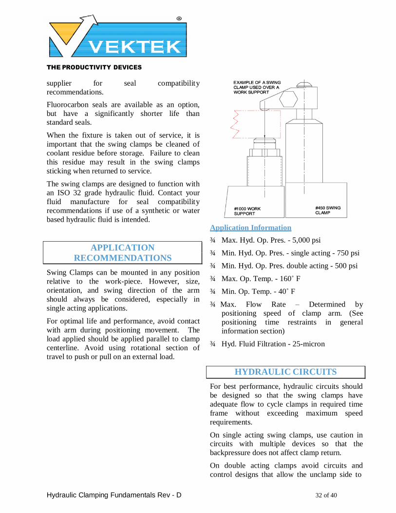
APPLICATION
RECOMMENDATIONS
Swing Clamps can be mounted in any position
relative to the work-piece. However, size,
orientation, and swing direction of the arm
should always be considered, especially in
single acting applications.
For optimal life and performance, avoid contact
with arm during positioning movement. The
load applied should be applied parallel to clamp
centerline. Avoid using rotational section of
travel to push or pull on an external load.
Application Information
¾ Max. Hyd. Op. Pres. - 5,000 psi
¾ Min. Hyd. Op. Pres. - single acting - 750 psi
¾ Min. Hyd. Op. Pres. double acting - 500 psi
¾ Max. Op. Temp. - 160˚ F
¾ Min. Op. Temp. - 40˚ F
¾ Max. Flow Rate – Determined by
positioning speed of clamp arm. (See
positioning time restraints in general
information section)
¾ Hyd. Fluid Filtration - 25-micron
HYDRAULIC CIRCUITS
For best performance, hydraulic circuits should
be designed so that the swing clamps have
adequate flow to cycle clamps in required time
frame without exceeding maximum speed
requirements.
On single acting swing clamps, use caution in circuits with multiple devices so that the
backpressure does not affect clamp return.
On double acting clamps avoid circuits and
control designs that allow the unclamp side to
THE PRODUCTIVITY DEVICES
COMPANY
Hydraulic Clamping Fundamentals Rev - D 33 of 40
be pressurized at the same time as the clamp
side; this creates a pressure intensification
situation that could prove to be detrimental to
clamp components.
In general, do not use spool valves to operate a
clamping circuit. The permissible leakage in a
spool valve can create problems with return of
clamps, pressure intensification situations and
general poor circuit performance. See your
VektorFlo® catalog for styles of valves
compatible with work holding hydraulic
circuits.
Always provide enough timing or provide
proper sequencing to insure complete
engagement of swing clamps before
manufacturing process is started.
On single acting clamps that are positioned in
the fixture so that they are either covered in
coolant or subjected to high pressure coolant
spray in the breather area, consideration should
be given to piping the breather port to a location
free from coolant saturation or to a chamber
having at least ten times the total clamp volume.
THE PRODUCTIVITY DEVICES
COMPANY
Hydraulic Clamping Fundamentals Rev - D 34 of 40
SECTION IV CYLINDERS
cylinder applying pull load (pull cylinder). They GENERAL DESCRIPTION
Cylinders are linear actuation devices that are
typically used to keep a work piece stationary or
move work piece into position.
They provide axial clamping force proportional
to the hydraulic pressure applied.
Mounting styles
Many sizes of cylinder are available in multiple
body styles to allow for maximum flexibility in
fixture design and plumbing arrangements. The
following illustration gives a general guide of
available mounting configurations. Note that not
all sizes are available in all body configurations.
Fluorocarbon seals are available for many
applications. See your VEKTORFLO® catalog
or give us a call for specific data.
Clamping force/stroke ranges
Vektek, Inc. offers cylinders in applied forces
ranging from 125 lbs to 12,000 lbs. All clamp
forces are given at 5,000-psi hydraulic
pressures. Strokes from .12 to 2.00 model
dependant.
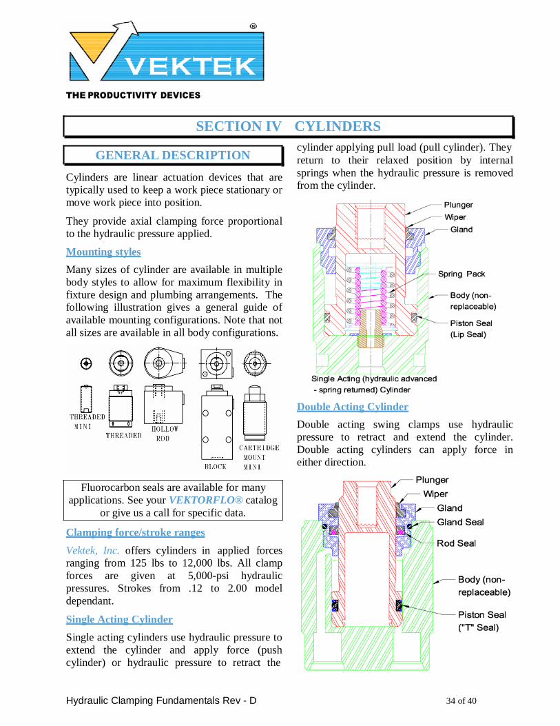
Single Acting Cylinder
Single acting cylinders use hydraulic pressure to
extend the cylinder and apply force (push
cylinder) or hydraulic pressure to retract the
return to their relaxed position by internal
springs when the hydraulic pressure is removed
from the cylinder.
Double Acting Cylinder
Double acting swing clamps use hydraulic
pressure to retract and extend the cylinder.
Double acting cylinders can apply force in
either direction.
THE PRODUCTIVITY DEVICES
COMPANY
Hydraulic Clamping Fundamentals Rev - D 35 of 40
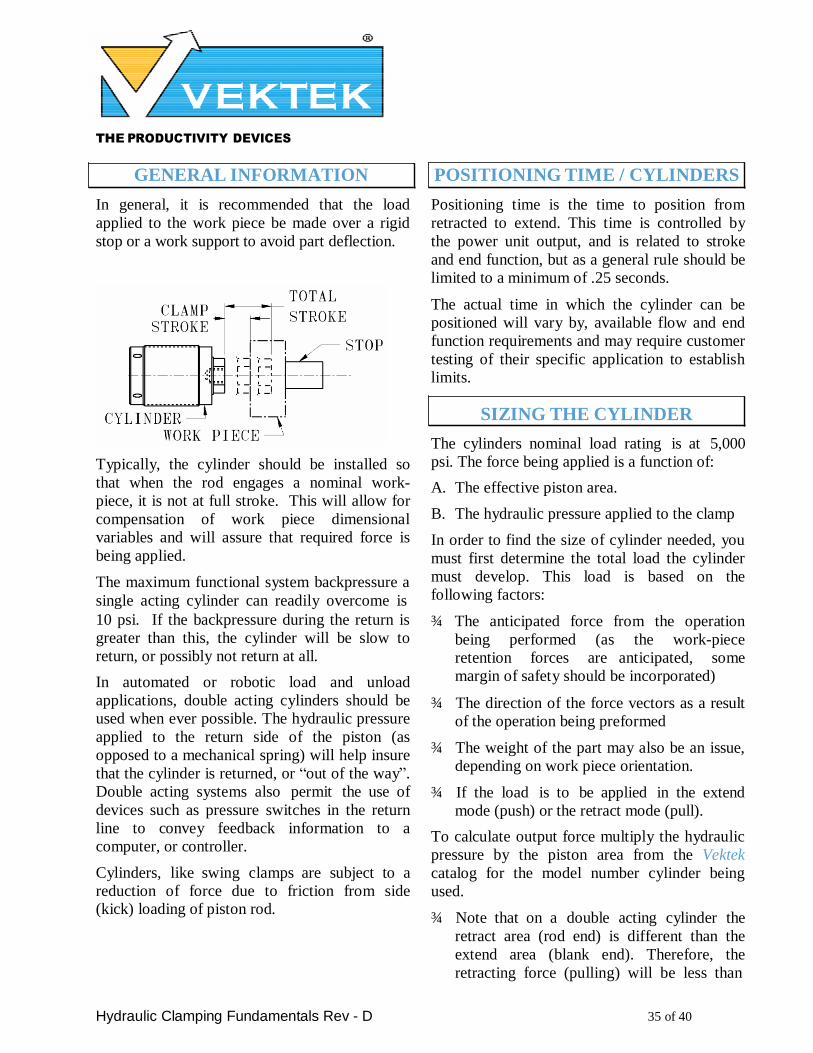
GENERAL INFORMATION
In general, it is recommended that the load
applied to the work piece be made over a rigid
stop or a work support to avoid part deflection.
Typically, the cylinder should be installed so
that when the rod engages a nominal work-
piece, it is not at full stroke. This will allow for
compensation of work piece dimensional
variables and will assure that required force is
being applied.
The maximum functional system backpressure a
single acting cylinder can readily overcome is
10 psi. If the backpressure during the return is
greater than this, the cylinder will be slow to
return, or possibly not return at all.
In automated or robotic load and unload
applications, double acting cylinders should be
used when ever possible. The hydraulic pressure
applied to the return side of the piston (as
opposed to a mechanical spring) will help insure
that the cylinder is returned, or “out of the way”.
Double acting systems also permit the use of
devices such as pressure switches in the return
line to convey feedback information to a
computer, or controller.
Cylinders, like swing clamps are subject to a
reduction of force due to friction from side (kick) loading of piston rod.
POSITIONING TIME / CYLINDERS
Positioning time is the time to position from
retracted to extend. This time is controlled by
the power unit output, and is related to stroke
and end function, but as a general rule should be
limited to a minimum of .25 seconds.
The actual time in which the cylinder can be
positioned will vary by, available flow and end
function requirements and may require customer
testing of their specific application to establish
limits.
SIZING THE CYLINDER
The cylinders nominal load rating is at 5,000
psi. The force being applied is a function of:
A. The effective piston area.
B. The hydraulic pressure applied to the clamp
In order to find the size of cylinder needed, you
must first determine the total load the cylinder
must develop. This load is based on the
following factors:
¾ The anticipated force from the operation
being performed (as the work-piece
retention forces are anticipated, some
margin of safety should be incorporated)
¾ The direction of the force vectors as a result
of the operation being preformed
¾ The weight of the part may also be an issue,
depending on work piece orientation.
¾ If the load is to be applied in the extend
mode (push) or the retract mode (pull).
To calculate output force multiply the hydraulic
pressure by the piston area from the Vektek
catalog for the model number cylinder being
used.
¾ Note that on a double acting cylinder the
retract area (rod end) is different than the
extend area (blank end). Therefore, the
retracting force (pulling) will be less than
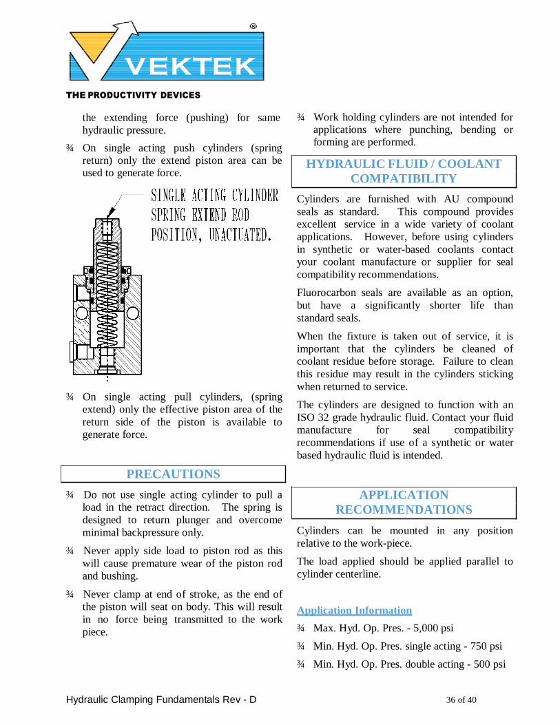
THE PRODUCTIVITY DEVICES
COMPANY
Hydraulic Clamping Fundamentals Rev - D 36 of 40
the extending force (pushing) for same
hydraulic pressure.
¾ On single acting push cylinders (spring
return) only the extend piston area can be used to generate force.
¾ On single acting pull cylinders, (spring
extend) only the effective piston area of the
return side of the piston is available to
generate force.
PRECAUTIONS
¾ Do not use single acting cylinder to pull a
load in the retract direction. The spring is
designed to return plunger and overcome
minimal backpressure only.
¾ Never apply side load to piston rod as this
will cause premature wear of the piston rod
and bushing.
¾ Never clamp at end of stroke, as the end of
the piston will seat on body. This will result
in no force being transmitted to the work
piece.
¾ Work holding cylinders are not intended for applications where punching, bending or
forming are performed.
HYDRAULIC FLUID / COOLANT
COMPATIBILITY
Cylinders are furnished with AU compound
seals as standard. This compound provides
excellent service in a wide variety of coolant
applications. However, before using cylinders
in synthetic or water-based coolants contact
your coolant manufacture or supplier for seal
compatibility recommendations.
Fluorocarbon seals are available as an option,
but have a significantly shorter life than
standard seals.
When the fixture is taken out of service, it is
important that the cylinders be cleaned of
coolant residue before storage. Failure to clean
this residue may result in the cylinders sticking
when returned to service.
The cylinders are designed to function with an
ISO 32 grade hydraulic fluid. Contact your fluid
manufacture for seal compatibility
recommendations if use of a synthetic or water
based hydraulic fluid is intended.
APPLICATION
RECOMMENDATIONS
Cylinders can be mounted in any position
relative to the work-piece.
The load applied should be applied parallel to
cylinder centerline.
Application Information
¾ Max. Hyd. Op. Pres. - 5,000 psi
¾ Min. Hyd. Op. Pres. single acting - 750 psi
¾ Min. Hyd. Op. Pres. double acting - 500 psi
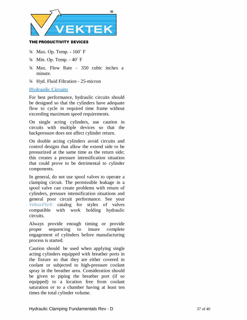
THE PRODUCTIVITY DEVICES
COMPANY
Hydraulic Clamping Fundamentals Rev - D 37 of 40
¾ Max. Op. Temp. - 160˚ F
¾ Min. Op. Temp. - 40˚ F
¾ Max. Flow Rate – 350 cubic inches a
minute.
¾ Hyd. Fluid Filtration - 25-micron
Hydraulic Circuits
For best performance, hydraulic circuits should
be designed so that the cylinders have adequate
flow to cycle in required time frame without
exceeding maximum speed requirements.
On single acting cylinders, use caution in circuits with multiple devices so that the
backpressure does not affect cylinder return.
On double acting cylinders avoid circuits and
control designs that allow the extend side to be
pressurized at the same time as the return side;
this creates a pressure intensification situation
that could prove to be detrimental to cylinder
components.
In general, do not use spool valves to operate a
clamping circuit. The permissible leakage in a
spool valve can create problems with return of
cylinders, pressure intensification situations and
general poor circuit performance. See your
VektorFlo® catalog for styles of valves
compatible with work holding hydraulic
circuits.
Always provide enough timing or provide
proper sequencing to insure complete
engagement of cylinders before manufacturing
process is started.
Caution should be used when applying single
acting cylinders equipped with breather ports in
the fixture so that they are either covered in
coolant or subjected to high-pressure coolant
spray in the breather area. Consideration should
be given to piping the breather port (if so
equipped) to a location free from coolant
saturation or to a chamber having at least ten
times the total cylinder volume.
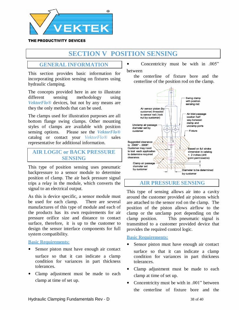
THE PRODUCTIVITY DEVICES
COMPANY
Hydraulic Clamping Fundamentals Rev - D 38 of 40
SECTION V POSITION SENSING
GENERAL INFORMATION
This section provides basic information for
incorporating position sensing on fixtures using hydraulic clamping.
The concepts provided here in are to illustrate
different sensing methodology using
VektorFlo® devices, but not by any means are
they the only methods that can be used.
The clamps used for illustration purposes are all
bottom flange swing clamps. Other mounting
styles of clamps are available with position
sensing options. Please see the VektorFlo®
catalog or contact your VektorFlo® sales
representative for additional information.
AIR LOGIC or BACK PRESSURE
SENSING
This type of position sensing uses pneumatic
backpressure to a sensor module to determine
position of clamp. The air back pressure signal
trips a relay in the module, which converts the
signal to an electrical output.
As this is device specific, a sensor module must
be used for each clamp. There are several
manufactures of this type of module and each of
the products has its own requirements for air
pressure orifice size and distance to contact
surface, therefore, it is up to the customer to
design the sensor interface components for full
system compatibility.
Basic Requirements:
• Sensor piston must have enough air contact
surface so that it can indicate a clamp condition for variances in part thickness tolerances.
• Clamp adjustment must be made to each
clamp at time of set up.
• Concentricity must be with in .005”
between the centerline of fixture bore and the centerline of the position rod on the clamp.
AIR PRESSURE SENSING
This type of sensing allows air into a cavity
around the customer provided air pistons which
are attached to the sensor rod on the clamp. The
position of the piston allows airflow to the
clamp or the unclamp port depending on the
clamp position. This pneumatic signal is
transmitted to a customer provided device that
provides the required control logic.
Basic Requirements:
• Sensor piston must have enough air contact
surface so that it can indicate a clamp condition for variances in part thickness tolerances.
• Clamp adjustment must be made to each
clamp at time of set up.
• Concentricity must be with in .001” between
the centerline of fixture bore and the

THE PRODUCTIVITY DEVICES
COMPANY
Hydraulic Clamping Fundamentals Rev - D 39 of 40
centerline of the position rod on the clamp.
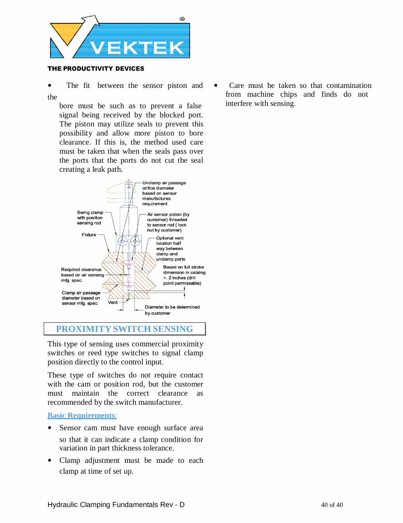
THE PRODUCTIVITY DEVICES
COMPANY
Hydraulic Clamping Fundamentals Rev - D 40 of 40
• The fit between the sensor piston and
the bore must be such as to prevent a false signal being received by the blocked port.
The piston may utilize seals to prevent this
possibility and allow more piston to bore
clearance. If this is, the method used care
must be taken that when the seals pass over
the ports that the ports do not cut the seal
creating a leak path.
PROXIMITY SWITCH SENSING
This type of sensing uses commercial proximity switches or reed type switches to signal clamp
position directly to the control input.
These type of switches do not require contact
with the cam or position rod, but the customer
must maintain the correct clearance as
recommended by the switch manufacturer.
Basic Requirements:
• Sensor cam must have enough surface area
so that it can indicate a clamp condition for variation in part thickness tolerance.
• Clamp adjustment must be made to each
clamp at time of set up.
• Care must be taken so that contamination from machine chips and finds do not interfere with sensing.
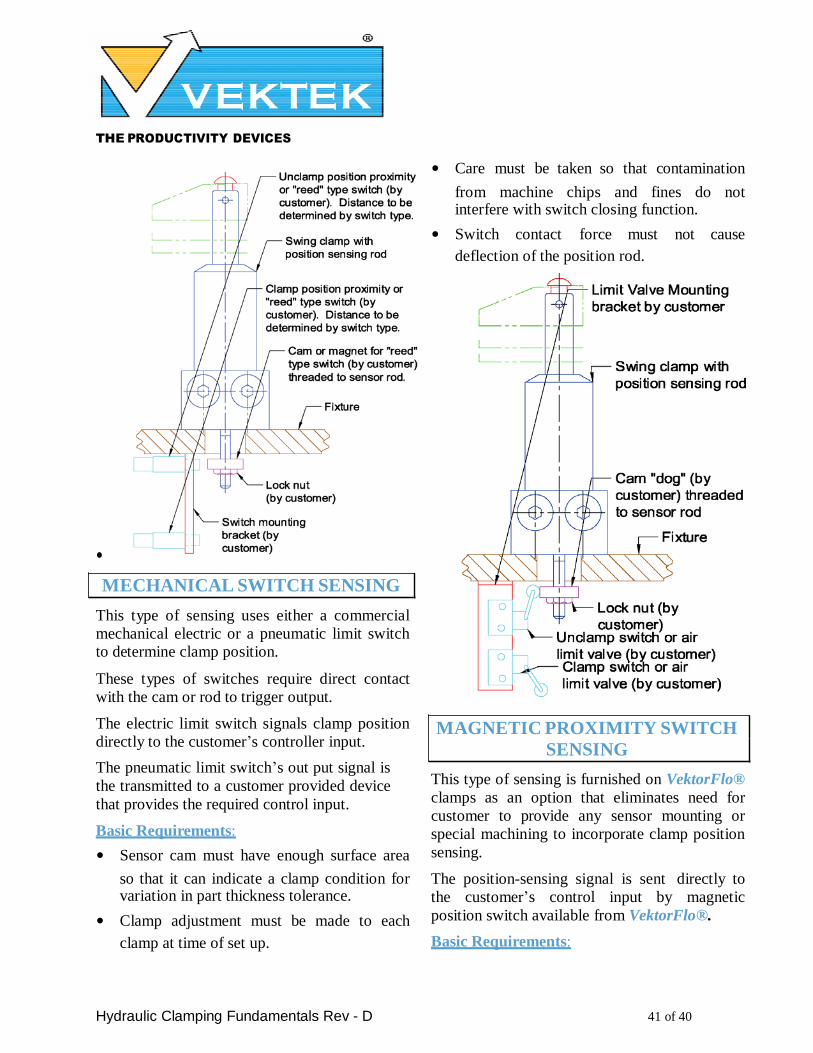
THE PRODUCTIVITY DEVICES
COMPANY
Hydraulic Clamping Fundamentals Rev - D 41 of 40
•
MECHANICAL SWITCH SENSING
This type of sensing uses either a commercial
mechanical electric or a pneumatic limit switch to determine clamp position.
These types of switches require direct contact
with the cam or rod to trigger output.
The electric limit switch signals clamp position
directly to the customer’s controller input.
The pneumatic limit switch’s out put signal is
the transmitted to a customer provided device
that provides the required control input.
Basic Requirements:
• Sensor cam must have enough surface area
so that it can indicate a clamp condition for variation in part thickness tolerance.
• Clamp adjustment must be made to each
clamp at time of set up.
• Care must be taken so that contamination
from machine chips and fines do not interfere with switch closing function.
• Switch contact force must not cause
deflection of the position rod.
MAGNETIC PROXIMITY SWITCH
SENSING
This type of sensing is furnished on VektorFlo®
clamps as an option that eliminates need for
customer to provide any sensor mounting or
special machining to incorporate clamp position
sensing.
The position-sensing signal is sent directly to
the customer’s control input by magnetic
position switch available from VektorFlo®.
Basic Requirements:
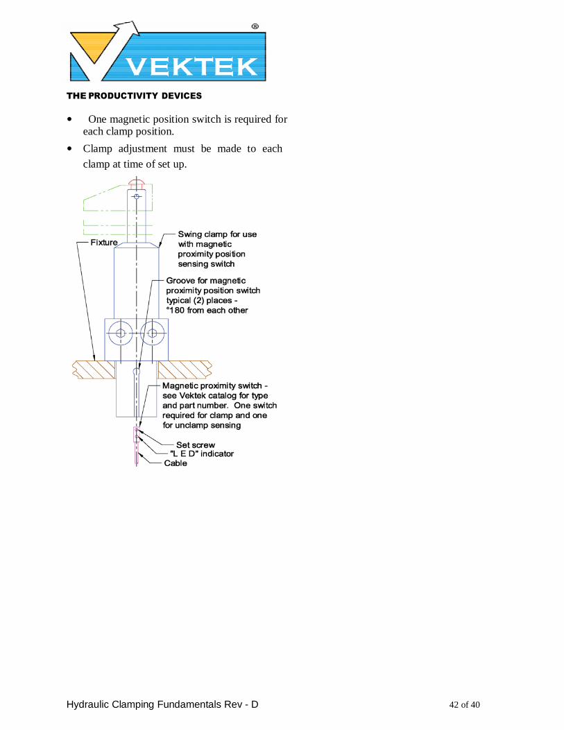
THE PRODUCTIVITY DEVICES
COMPANY
Hydraulic Clamping Fundamentals Rev - D 42 of 40
• One magnetic position switch is required for each clamp position.
• Clamp adjustment must be made to each
clamp at time of set up.