Embed Size (px)
Citation preview
Gateway Plaza Elizabeth Hostutler Wilmington, DE Structural Option October 31, 2005 Advisor: Linda Hanagan
Technical Report 2: Pro-Con Structural Study of Alternate Floor Systems
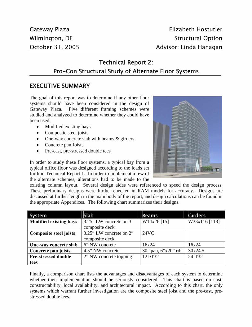
EXECUTIVE SUMMARY The goal of this report was to determine if any other floor systems should have been considered in the design of Gateway Plaza. Five different framing schemes were studied and analyzed to determine whether they could have been used.
• Modified existing bays • Composite steel joists • One-way concrete slab with beams & girders • Concrete pan Joists • Pre-cast, pre-stressed double tees
In order to study these floor systems, a typical bay from a typical office floor was designed according to the loads set forth in Technical Report 1. In order to implement a few of the alternate schemes, alterations had to be made to the existing column layout. Several design aides were referenced to speed the design process. These preliminary designs were further checked in RAM models for accuracy. Designs are discussed at further length in the main body of the report, and design calculations can be found in the appropriate Appendices. The following chart summarizes their designs. System Slab Beams Girders Modified existing bays 3.25” LW concrete on 3”
composite deck W14x26 [15] W33x116 [118]
Composite steel joists 3.25” LW concrete on 2” composite deck
24VC
One-way concrete slab 6” NW concrete 16x24 16x24 Concrete pan joists 4.5” NW concrete 30” pan, 6”x20” rib 30x24.5 Pre-stressed double tees
2” NW concrete topping 12DT32 24IT32
Finally, a comparison chart lists the advantages and disadvantages of each system to determine whether their implementation should be seriously considered. This chart is based on cost, constructability, local availability, and architectural impact. According to this chart, the only systems which warrant further investigation are the composite steel joist and the pre-cast, pre-stressed double tees.
Technical Assignment 2: Alternate Framing System
2
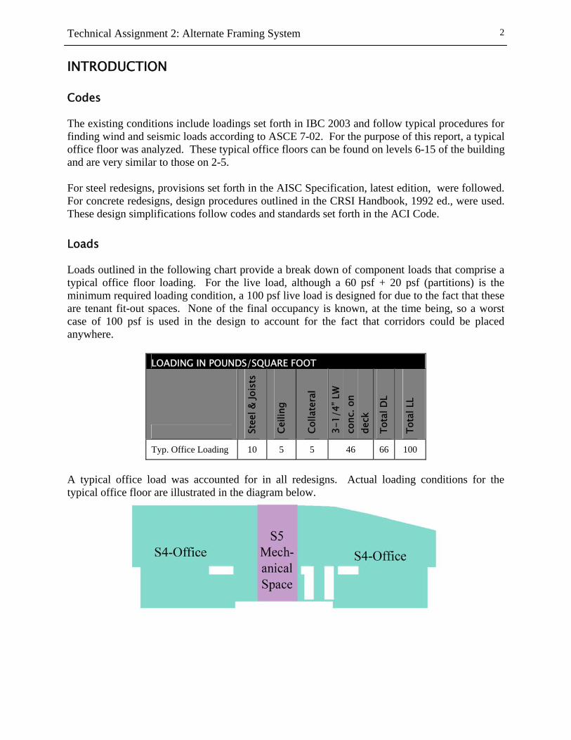
INTRODUCTION Codes The existing conditions include loadings set forth in IBC 2003 and follow typical procedures for finding wind and seismic loads according to ASCE 7-02. For the purpose of this report, a typical office floor was analyzed. These typical office floors can be found on levels 6-15 of the building and are very similar to those on 2-5. For steel redesigns, provisions set forth in the AISC Specification, latest edition, were followed. For concrete redesigns, design procedures outlined in the CRSI Handbook, 1992 ed., were used. These design simplifications follow codes and standards set forth in the ACI Code. Loads Loads outlined in the following chart provide a break down of component loads that comprise a typical office floor loading. For the live load, although a 60 psf + 20 psf (partitions) is the minimum required loading condition, a 100 psf live load is designed for due to the fact that these are tenant fit-out spaces. None of the final occupancy is known, at the time being, so a worst case of 100 psf is used in the design to account for the fact that corridors could be placed anywhere.
LOADING IN POUNDS/SQUARE FOOT
Stee
l & Jo
ists
Ceili
ng
Colla
tera
l
3-1/
4” L
W
conc
. on
deck
Tota
l DL
Tota
l LL
Typ. Office Loading 10 5 5 46 66 100
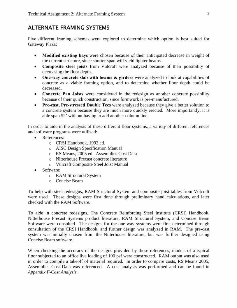
A typical office load was accounted for in all redesigns. Actual loading conditions for the typical office floor are illustrated in the diagram below.
Technical Assignment 2: Alternate Framing System
3
ALTERNATE FRAMING SYSTEMS Five different framing schemes were explored to determine which option is best suited for Gateway Plaza:
• Modified existing bays were chosen because of their anticipated decrease in weight of the current structure, since shorter span will yield lighter beams.
• Composite steel joists from Vulcraft were analyzed because of their possibility of decreasing the floor depth.
• One-way concrete slab with beams & girders were analyzed to look at capabilities of concrete as a viable framing option, and to determine whether floor depth could be decreased.
• Concrete Pan Joists were considered in the redesign as another concrete possibility because of their quick construction, since formwork is pre-manufactured.
• Pre-cast, Pre-stressed Double Tees were analyzed because they give a better solution to a concrete system because they are much more quickly erected. More importantly, it is able span 52’ without having to add another column line.
In order to aide in the analysis of these different floor systems, a variety of different references and software programs were utilized:
• References: o CRSI Handbook, 1992 ed. o AISC Design Specification Manual o RS Means, 2005 ed. Assemblies Cost Data o Nitterhouse Precast concrete literature o Vulcraft Composite Steel Joist Manual
• Software: o RAM Structural System o Concise Beam
To help with steel redesigns, RAM Structural System and composite joist tables from Vulcraft were used. These designs were first done through preliminary hand calculations, and later checked with the RAM Software. To aide in concrete redesigns, The Concrete Reinforcing Steel Institute (CRSI) Handbook, Nitterhouse Precast Systems product literature, RAM Structural System, and Concise Beam Software were consulted. The designs for the one-way systems were first determined through consultation of the CRSI Handbook, and further design was analyzed in RAM. The pre-cast system was initially chosen from the Nitterhouse literature, but was further designed using Concise Beam software. When checking the accuracy of the designs provided by these references, models of a typical floor subjected to an office live loading of 100 psf were constructed. RAM output was also used in order to compile a takeoff of material required. In order to compare costs, RS Means 2005, Assemblies Cost Data was referenced. A cost analysis was performed and can be found in Appendix F-Cost Analysis.
Technical Assignment 2: Alternate Framing System
4
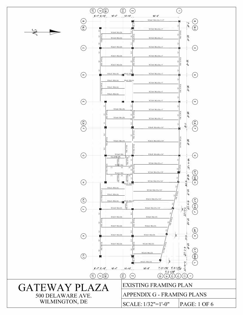
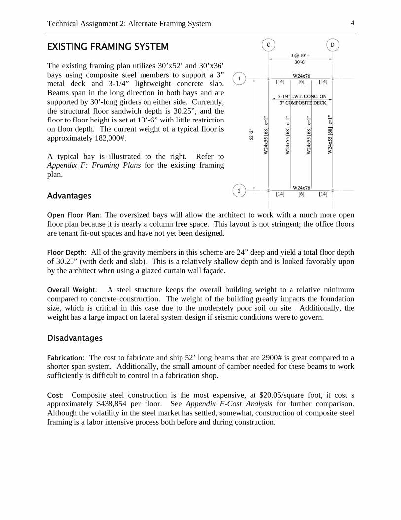
EXISTING FRAMING SYSTEM The existing framing plan utilizes 30’x52’ and 30’x36’ bays using composite steel members to support a 3” metal deck and 3-1/4” lightweight concrete slab. Beams span in the long direction in both bays and are supported by 30’-long girders on either side. Currently, the structural floor sandwich depth is 30.25”, and the floor to floor height is set at 13’-6” with little restriction on floor depth. The current weight of a typical floor is approximately 182,000#. A typical bay is illustrated to the right. Refer to Appendix F: Framing Plans for the existing framing plan. Advantages Open Floor Plan: The oversized bays will allow the architect to work with a much more open floor plan because it is nearly a column free space. This layout is not stringent; the office floors are tenant fit-out spaces and have not yet been designed. Floor Depth: All of the gravity members in this scheme are 24” deep and yield a total floor depth of 30.25” (with deck and slab). This is a relatively shallow depth and is looked favorably upon by the architect when using a glazed curtain wall façade. Overall Weight: A steel structure keeps the overall building weight to a relative minimum compared to concrete construction. The weight of the building greatly impacts the foundation size, which is critical in this case due to the moderately poor soil on site. Additionally, the weight has a large impact on lateral system design if seismic conditions were to govern. Disadvantages Fabrication: The cost to fabricate and ship 52’ long beams that are 2900# is great compared to a shorter span system. Additionally, the small amount of camber needed for these beams to work sufficiently is difficult to control in a fabrication shop. Cost: Composite steel construction is the most expensive, at $20.05/square foot, it cost s approximately $438,854 per floor. See Appendix F-Cost Analysis for further comparison. Although the volatility in the steel market has settled, somewhat, construction of composite steel framing is a labor intensive process both before and during construction.
Technical Assignment 2: Alternate Framing System
5
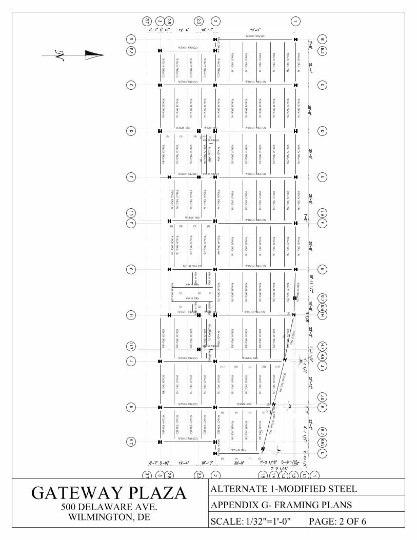
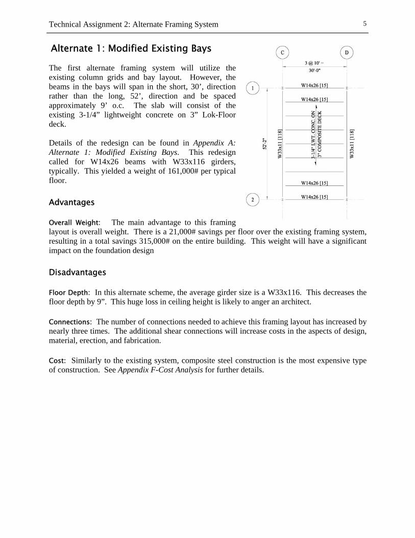
Alternate 1: Modified Existing Bays The first alternate framing system will utilize the existing column grids and bay layout. However, the beams in the bays will span in the short, 30’, direction rather than the long, 52’, direction and be spaced approximately 9’ o.c. The slab will consist of the existing 3-1/4” lightweight concrete on 3” Lok-Floor deck. Details of the redesign can be found in Appendix A: Alternate 1: Modified Existing Bays. This redesign called for W14x26 beams with W33x116 girders, typically. This yielded a weight of 161,000# per typical floor. Advantages Overall Weight: The main advantage to this framing layout is overall weight. There is a 21,000# savings per floor over the existing framing system, resulting in a total savings 315,000# on the entire building. This weight will have a significant impact on the foundation design Disadvantages Floor Depth: In this alternate scheme, the average girder size is a W33x116. This decreases the floor depth by 9”. This huge loss in ceiling height is likely to anger an architect. Connections: The number of connections needed to achieve this framing layout has increased by nearly three times. The additional shear connections will increase costs in the aspects of design, material, erection, and fabrication. Cost: Similarly to the existing system, composite steel construction is the most expensive type of construction. See Appendix F-Cost Analysis for further details.
Technical Assignment 2: Alternate Framing System
6
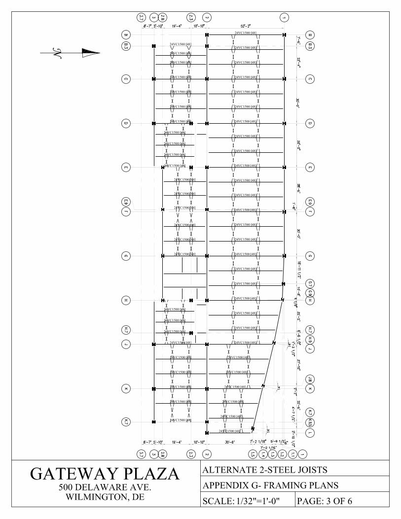
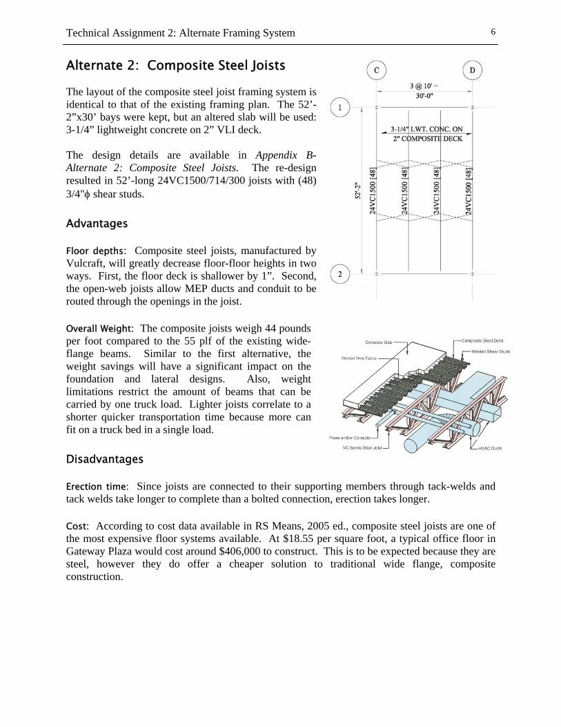
Alternate 2: Composite Steel Joists The layout of the composite steel joist framing system is identical to that of the existing framing plan. The 52’-2”x30’ bays were kept, but an altered slab will be used: 3-1/4” lightweight concrete on 2” VLI deck. The design details are available in Appendix B- Alternate 2: Composite Steel Joists. The re-design resulted in 52’-long 24VC1500/714/300 joists with (48) 3/4"φ shear studs. Advantages Floor depths: Composite steel joists, manufactured by Vulcraft, will greatly decrease floor-floor heights in two ways. First, the floor deck is shallower by 1”. Second, the open-web joists allow MEP ducts and conduit to be routed through the openings in the joist. Overall Weight: The composite joists weigh 44 pounds per foot compared to the 55 plf of the existing wide-flange beams. Similar to the first alternative, the weight savings will have a significant impact on the foundation and lateral designs. Also, weight limitations restrict the amount of beams that can be carried by one truck load. Lighter joists correlate to a shorter quicker transportation time because more can fit on a truck bed in a single load. Disadvantages Erection time: Since joists are connected to their supporting members through tack-welds and tack welds take longer to complete than a bolted connection, erection takes longer. Cost: According to cost data available in RS Means, 2005 ed., composite steel joists are one of the most expensive floor systems available. At $18.55 per square foot, a typical office floor in Gateway Plaza would cost around $406,000 to construct. This is to be expected because they are steel, however they do offer a cheaper solution to traditional wide flange, composite construction.
Technical Assignment 2: Alternate Framing System
7
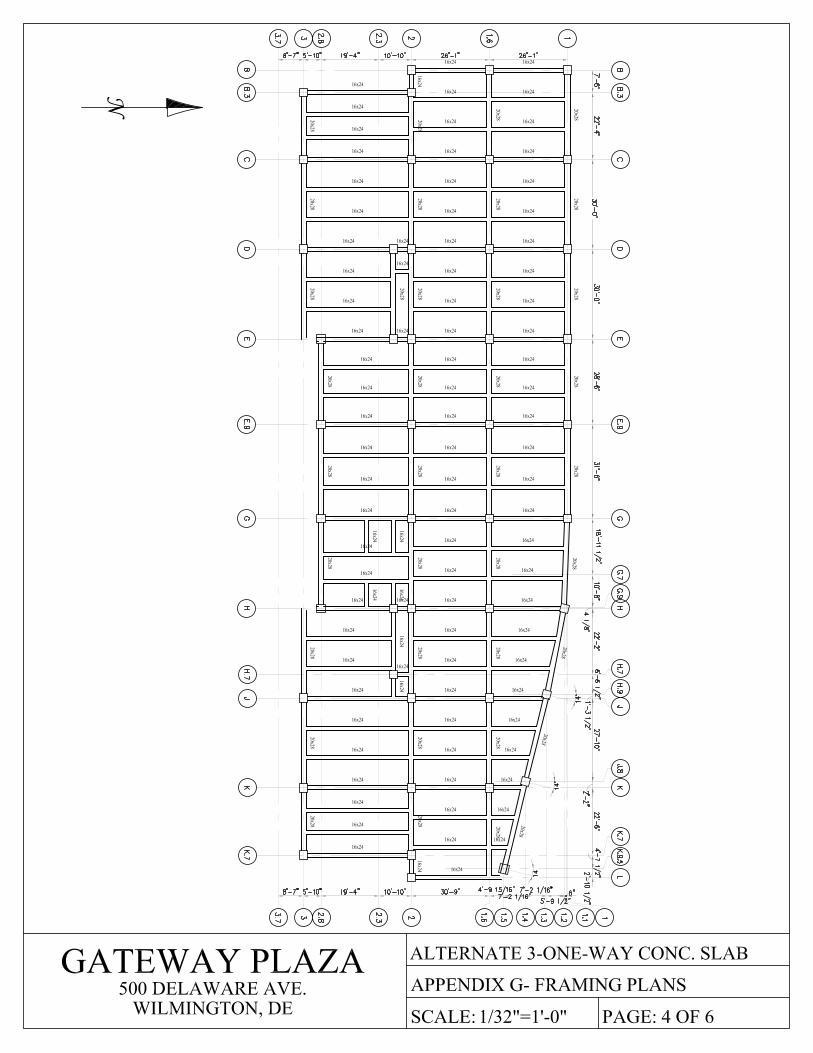
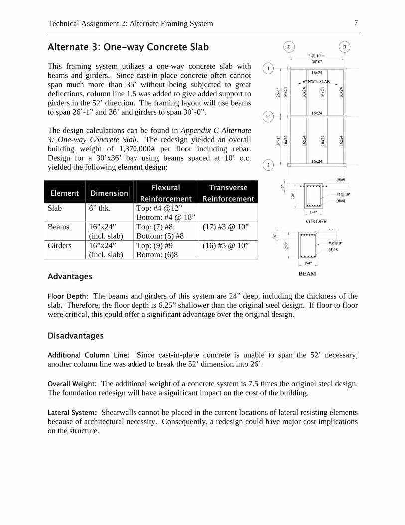
Alternate 3: One-way Concrete Slab This framing system utilizes a one-way concrete slab with beams and girders. Since cast-in-place concrete often cannot span much more than 35’ without being subjected to great deflections, column line 1.5 was added to give added support to girders in the 52’ direction. The framing layout will use beams to span 26’-1” and 36’ and girders to span 30’-0”. The design calculations can be found in Appendix C-Alternate 3: One-way Concrete Slab. The redesign yielded an overall building weight of 1,370,000# per floor including rebar. Design for a 30’x36’ bay using beams spaced at 10’ o.c. yielded the following element design:
Advantages Floor Depth: The beams and girders of this system are 24” deep, including the thickness of the slab. Therefore, the floor depth is 6.25” shallower than the original steel design. If floor to floor were critical, this could offer a significant advantage over the original design. Disadvantages Additional Column Line: Since cast-in-place concrete is unable to span the 52’ necessary, another column line was added to break the 52’ dimension into 26’. Overall Weight: The additional weight of a concrete system is 7.5 times the original steel design. The foundation redesign will have a significant impact on the cost of the building. Lateral System: Shearwalls cannot be placed in the current locations of lateral resisting elements because of architectural necessity. Consequently, a redesign could have major cost implications on the structure.
Element Dimension Flexural
Reinforcement Transverse
ReinforcementSlab 6” thk. Top: #4 @12”
Bottom: #4 @ 18”
Beams 16”x24” (incl. slab)
Top: (7) #8 Bottom: (5) #8
(17) #3 @ 10”
Girders 16”x24” (incl. slab)
Top: (9) #9 Bottom: (6)8
(16) #5 @ 10”
Technical Assignment 2: Alternate Framing System
8
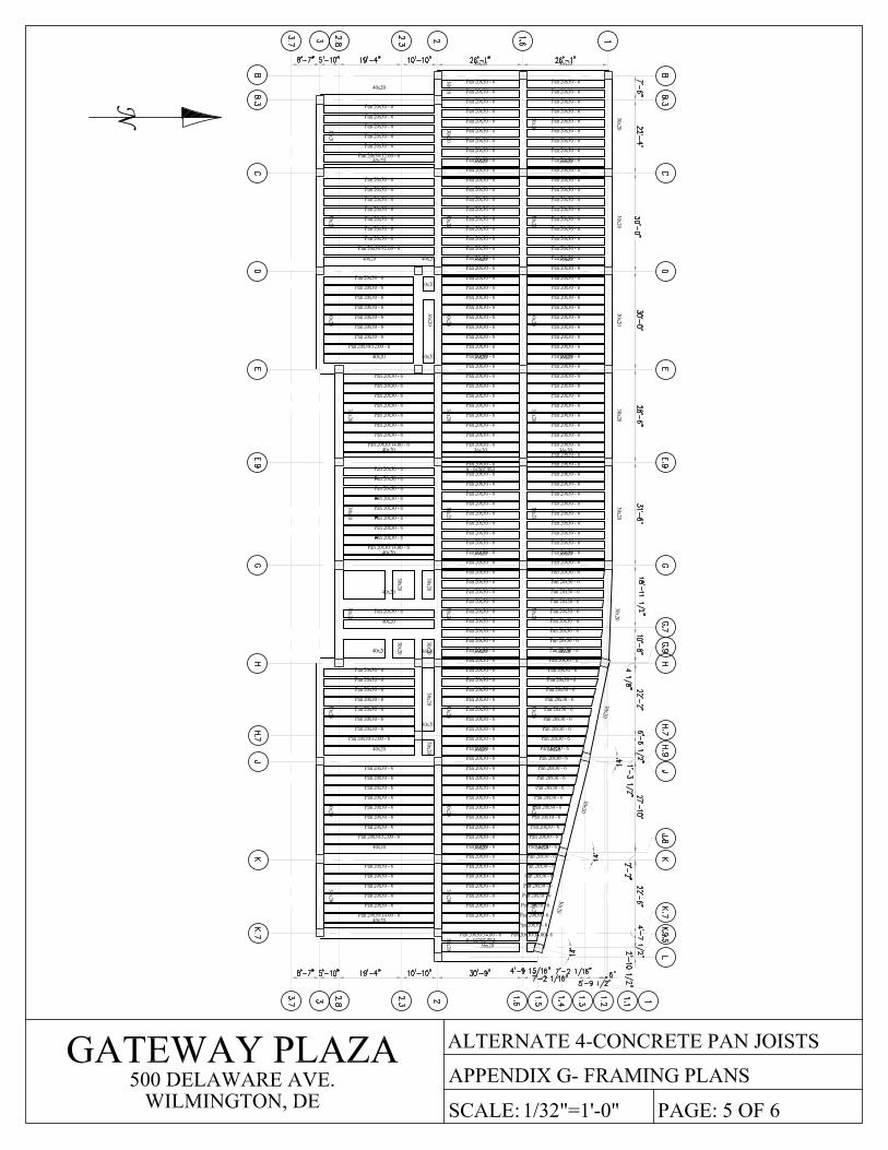
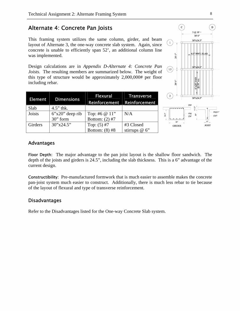
Alternate 4: Concrete Pan Joists This framing system utilizes the same column, girder, and beam layout of Alternate 3, the one-way concrete slab system. Again, since concrete is unable to efficiently span 52’, an additional column line was implemented. Design calculations are in Appendix D-Alternate 4: Concrete Pan Joists. The resulting members are summarized below. The weight of this type of structure would be approximately 2,000,000# per floor including rebar.
Advantages Floor Depth: The major advantage to the pan joist layout is the shallow floor sandwich. The depth of the joists and girders is 24.5”, including the slab thickness. This is a 6” advantage of the current design. Constructibility: Pre-manufactured formwork that is much easier to assemble makes the concrete pan-joist system much easier to construct. Additionally, there is much less rebar to tie because of the layout of flexural and type of transverse reinforcement. Disadvantages Refer to the Disadvantages listed for the One-way Concrete Slab system.
Element Dimensions Flexural
Reinforcement Transverse
ReinforcementSlab 4.5” thk. Joists 6”x20” deep rib
30” form Top: #6 @ 11” Bottom: (2) #7
N/A
Girders 30”x24.5” Top: (5) #7 Bottom: (8) #8
#3 Closed stirrups @ 6”
Technical Assignment 2: Alternate Framing System
9
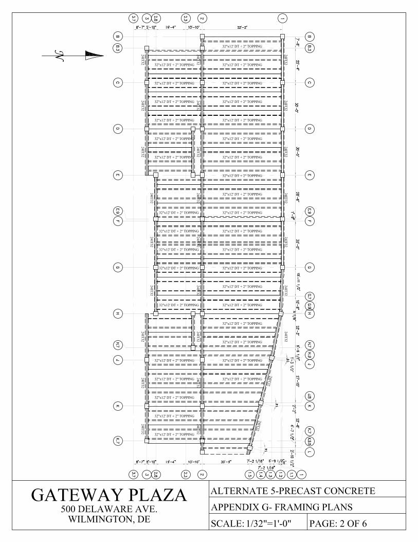
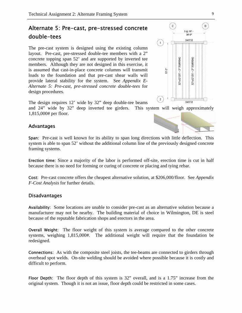
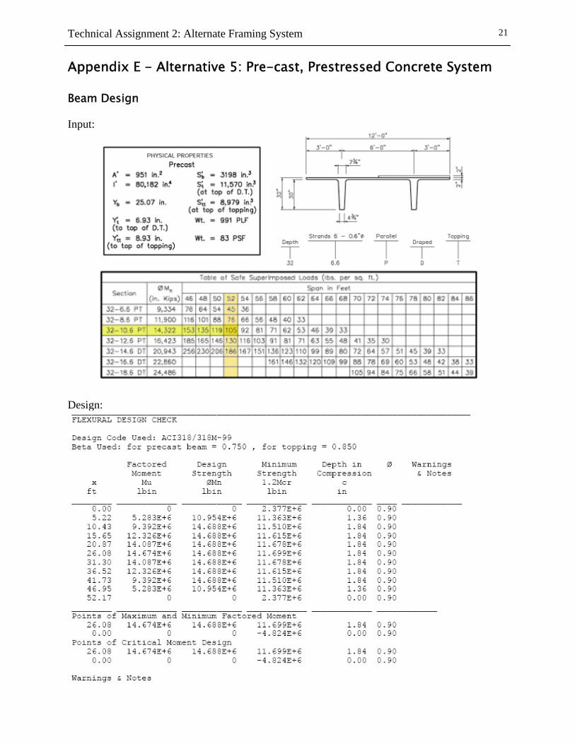
Alternate 5: Pre-cast, pre-stressed concrete double-tees The pre-cast system is designed using the existing column layout. Pre-cast, pre-stressed double-tee members with a 2” concrete topping span 52’ and are supported by inverted tee members. Although they are not designed in this exercise, it is assumed that cast-in-place concrete columns will transmit loads to the foundation and that pre-cast shear walls will provide lateral stability for the system. See Appendix E-Alternate 5: Pre-cast, pre-stressed concrete double-tees for design procedures. The design requires 12’ wide by 32” deep double-tee beams and 24” wide by 32” deep inverted tee girders. This system will weigh approximately 1,815,000# per floor. Advantages Span: Pre-cast is well known for its ability to span long directions with little deflection. This system is able to span 52’ without the additional column line of the previously designed concrete framing systems. Erection time: Since a majority of the labor is performed off-site, erection time is cut in half because there is no need for forming or curing of concrete or placing and tying rebar. Cost: Pre-cast concrete offers the cheapest alternative solution, at $206,000/floor. See Appendix F-Cost Analysis for further details. Disadvantages Availability: Some locations are unable to consider pre-cast as an alternative solution because a manufacturer may not be nearby. The building material of choice in Wilmington, DE is steel because of the reputable fabrication shops and erectors in the area. Overall Weight: The floor weight of this system is average compared to the other concrete systems, weighing 1,815,000#. The additional weight will require that the foundation be redesigned. Connections: As with the composite steel joists, the tee-beams are connected to girders through overhead spot welds. On-site welding should be avoided where possible because it is costly and difficult to perform.
Floor Depth: The floor depth of this system is 32” overall, and is a 1.75” increase from the original system. Though it is not an issue, floor depth could be restricted in some cases.
Technical Assignment 2: Alternate Framing System
10
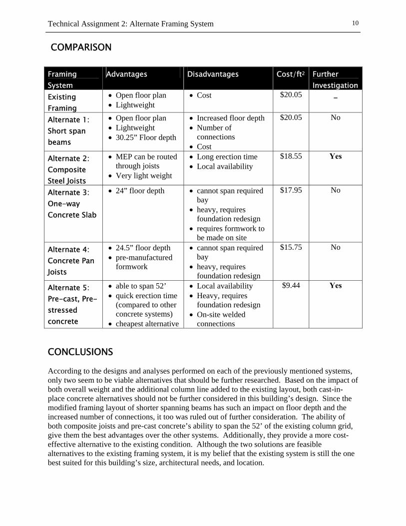
COMPARISON Framing System
Advantages Disadvantages Cost/ft2 Further Investigation
Existing Framing
• Open floor plan • Lightweight
• Cost $20.05 -
Alternate 1: Short span beams
• Open floor plan • Lightweight • 30.25” Floor depth
• Increased floor depth • Number of
connections • Cost
$20.05 No
Alternate 2: Composite Steel Joists
• MEP can be routed through joists
• Very light weight
• Long erection time • Local availability
$18.55 Yes
Alternate 3: One-way Concrete Slab
• 24” floor depth • cannot span required bay
• heavy, requires foundation redesign
• requires formwork to be made on site
$17.95 No
Alternate 4: Concrete Pan Joists
• 24.5” floor depth • pre-manufactured
formwork
• cannot span required bay
• heavy, requires foundation redesign
$15.75 No
Alternate 5: Pre-cast, Pre-stressed concrete
• able to span 52’ • quick erection time
(compared to other concrete systems)
• cheapest alternative
• Local availability • Heavy, requires
foundation redesign • On-site welded
connections
$9.44 Yes
CONCLUSIONS According to the designs and analyses performed on each of the previously mentioned systems, only two seem to be viable alternatives that should be further researched. Based on the impact of both overall weight and the additional column line added to the existing layout, both cast-in-place concrete alternatives should not be further considered in this building’s design. Since the modified framing layout of shorter spanning beams has such an impact on floor depth and the increased number of connections, it too was ruled out of further consideration. The ability of both composite joists and pre-cast concrete’s ability to span the 52’ of the existing column grid, give them the best advantages over the other systems. Additionally, they provide a more cost-effective alternative to the existing condition. Although the two solutions are feasible alternatives to the existing framing system, it is my belief that the existing system is still the one best suited for this building’s size, architectural needs, and location.
Technical Assignment 2: Alternate Framing System
11
APPENDICES
Technical Assignment 2: Alternate Framing System
12
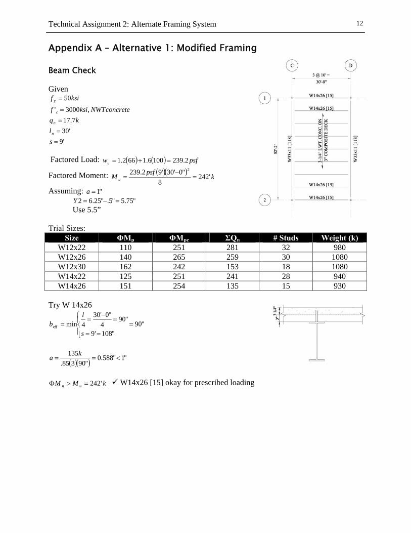
Appendix A – Alternative 1: Modified Framing Beam Check Given
'9'307.17
,3000'
50
====
=
sl
kqconcreteNWTksif
ksif
n
n
c
y
Factored Load: ( ) ( ) psfwu 2.2391006.1662.1 =+=
Factored Moment: ( )( )kpsfM u '242
8"0'30'92.239 2
=−
=
Assuming: "1=a "75.5"5."25.62 =−=Y Use 5.5” Trial Sizes:
Size ΦMp ΦMpc ΣQn # Studs Weight (k) W12x22 110 251 281 32 980 W12x26 140 265 259 30 1080 W12x30 162 242 153 18 1080 W14x22 125 251 241 28 940 W14x26 151 254 135 15 930
Try W 14x26
"90"108'9
"904
"0'304min =
⎪⎩
⎪⎨⎧
==
=−
==
s
lbeff
( )( ) "1"588.0"90385.
135<==
ka
kMM un '242=>Φ W14x26 [15] okay for prescribed loading
Technical Assignment 2: Alternate Framing System
13
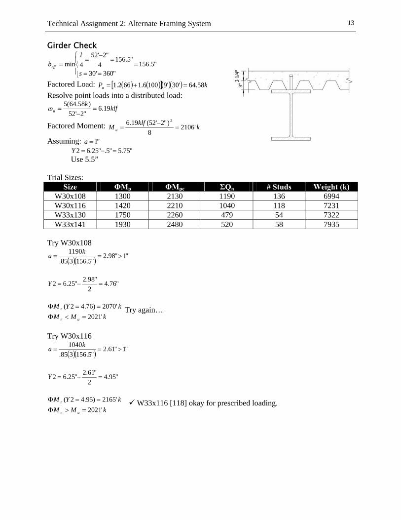
Girder Check
"5.156"360'30
"5.1564
"2'524min =
⎪⎩
⎪⎨⎧
==
=−
==
s
lbeff
Factored Load: ( ) ( )[ ]( )( ) kPu 58.64'30'91006.1662.1 =+= Resolve point loads into a distributed load:
klfku 19.6
"2'52)58.64(5=
−=ω
Factored Moment: kklfM u '21068
)"2'52(19.6 2
=−
=
Assuming: "1=a "75.5"5."25.62 =−=Y Use 5.5” Trial Sizes:
Size ΦMp ΦMpc ΣQn # Studs Weight (k) W30x108 1300 2130 1190 136 6994 W30x116 1420 2210 1040 118 7231 W33x130 1750 2260 479 54 7322 W33x141 1930 2480 520 58 7935
Try W30x108
( )( ) "1"98.2"5.156385.
1190>==
ka
"76.4
2"98.2"25.62 =−=Y
kMMkYM
un
n
'2021'2070)76.42(
=<Φ==Φ Try again…
Try W30x116
( )( ) "1"61.2"5.156385.
1040>==
ka
"95.4
2"61.2"25.62 =−=Y
kMMkYM
un
n
'2021'2165)95.42(
=>Φ==Φ W33x116 [118] okay for prescribed loading.
Technical Assignment 2: Alternate Framing System
14
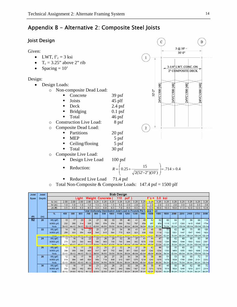
Appendix B - Alternative 2: Composite Steel Joists Joist Design Given:
• LWT, f’c = 3 ksi • Tc = 3.25” above 2” rib • Spacing = 10’
Design:
• Design Loads: o Non-composite Dead Load:
Concrete 39 psf Joists 45 plf Deck 2.4 psf Bridging 0.1 psf Total 46 psf
o Construction Live Load: 8 psf o Composite Dead Load:
Partitions 20 psf MEP 5 psf Ceiling/flooing 5 psf Total 30 psf
o Composite Live Load: Design Live Load 100 psf
Reduction: 4.0714.)'10)("2'52(2
1525.0 >=⎟⎟⎠
⎞⎜⎜⎝
⎛
−+=R
Reduced Live Load 71.4 psf o Total Non-Composite & Composite Loads: 147.4 psf = 1500 plf
Technical Assignment 2: Alternate Framing System
15
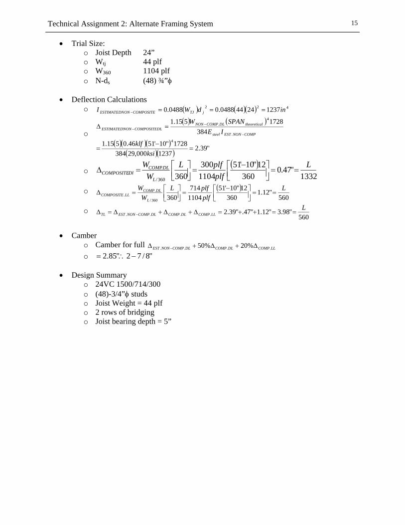
• Trial Size: o Joist Depth 24” o Wtj 44 plf o W360 1104 plf o N-ds (48) ¾”φ
• Deflection Calculations
o ( ) ( )( ) 422 123724440488.00488.0 indWI jTJCOMPOSITEONESTIMATEDN ===−
o ( ) ( )
( )( )( )( )( ) "39.2
1237000,293841728"10'5146.0515.1
3841728515.1
4.
4.
=−
=
=Δ−
−−
ksiklf
IESPANW
COMPNONESTsteel
ltheoreticaDLCOMPNONLCOMPOSITEDONESTIMATEDN
o ( )
1332"47.0
36012"10'51
1104300
360360/
..
LplfplfL
WW
L
DLCOMPDlCOMPOSITE ==⎥⎦
⎤⎢⎣⎡ −
=⎥⎦⎤
⎢⎣⎡=Δ
o ( )560
"12.1360
12"10'511104714
360360/
..
LplfplfL
WW
L
DLCOMPLLCOMPOSITE ==⎥⎦
⎤⎢⎣⎡ −
=⎥⎦⎤
⎢⎣⎡=Δ
o 560
"98.3"12.1"47."39.2....L
LLCOMPDLCOMPDLCOMPNONESTTL ==++=Δ+Δ+Δ=Δ −
• Camber
o Camber for full LLCOMPDLCOMPDLCOMPNONEST .... %20%50 Δ+Δ+Δ − o "8/72"85.2 −∴=
• Design Summary
o 24VC 1500/714/300 o (48)-3/4”φ studs o Joist Weight = 44 plf o 2 rows of bridging o Joist bearing depth = 5”
Technical Assignment 2: Alternate Framing System
16
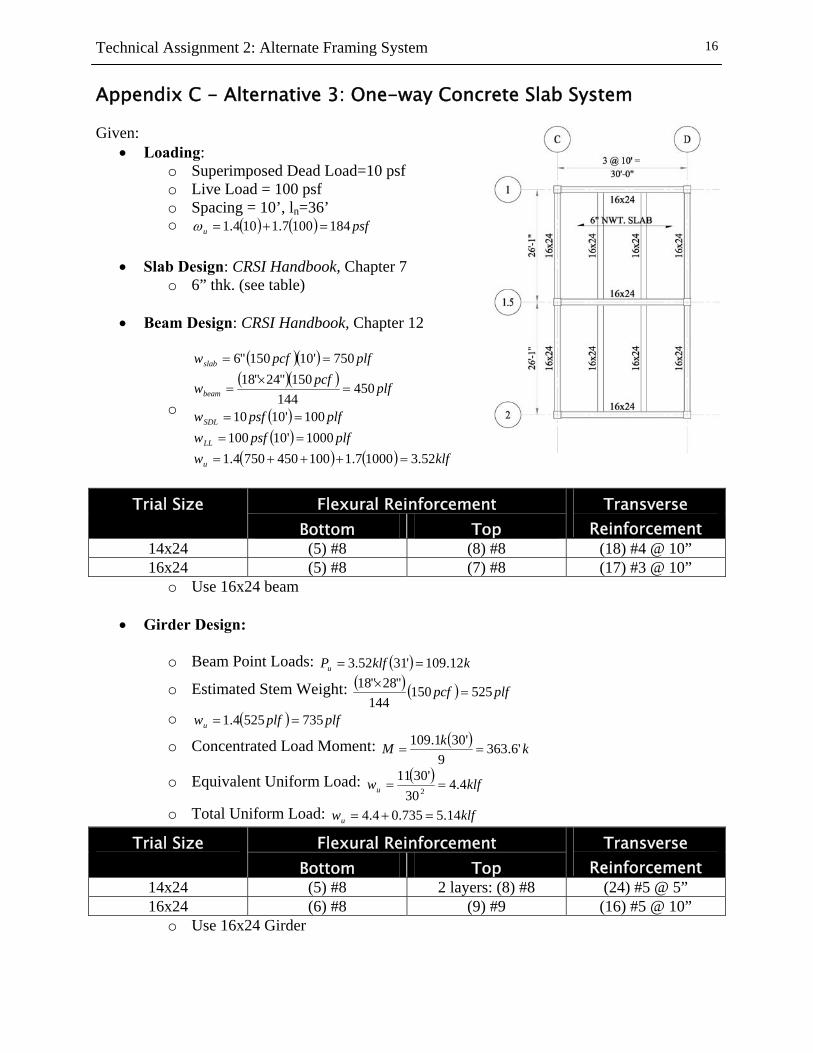
Appendix C - Alternative 3: One-way Concrete Slab System Given:
• Loading: o Superimposed Dead Load=10 psf o Live Load = 100 psf o Spacing = 10’, ln=36’ o ( ) ( ) psfu 1841007.1104.1 =+=ω
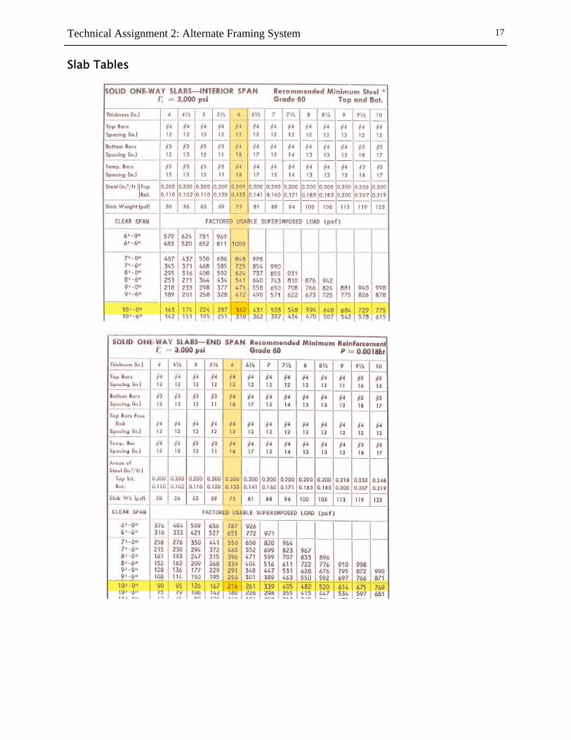
• Slab Design: CRSI Handbook, Chapter 7
o 6” thk. (see table)
• Beam Design: CRSI Handbook, Chapter 12
o
( )( )( )( )
( )( )
( ) ( ) klfwplfpsfw
plfpsfw
plfpcfw
plfpcfw
u
LL
SDL
beam
slab
52.310007.11004507504.11000'10100100'1010
450144
150"24"18750'10150"6
=+++=====
=×
=
==
Flexural Reinforcement Trial Size
Bottom Top Transverse
Reinforcement 14x24 (5) #8 (8) #8 (18) #4 @ 10” 16x24 (5) #8 (7) #8 (17) #3 @ 10”
o Use 16x24 beam
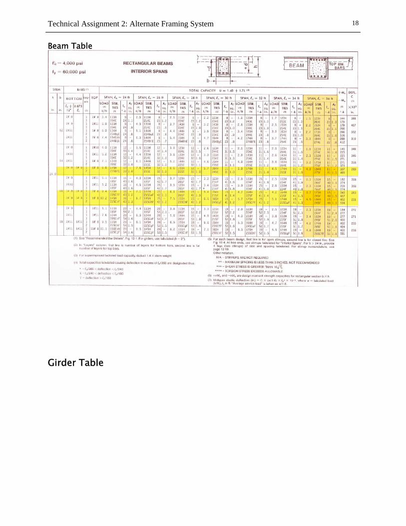
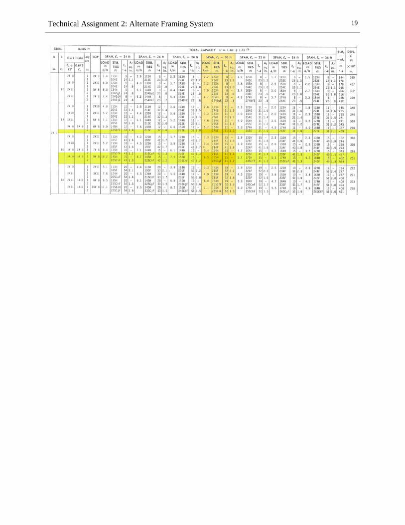
• Girder Design:
o Beam Point Loads: ( ) kklfPu 12.109'3152.3 ==
o Estimated Stem Weight: ( ) ( ) plfpcf 525150144
"28"18=
×
o ( ) plfplfwu 7355254.1 ==
o Concentrated Load Moment: ( ) kkM '6.3639
'301.109==
o Equivalent Uniform Load: ( ) klfwu 4.430
'30112 ==
o Total Uniform Load: klfwu 14.5735.04.4 =+=
Flexural Reinforcement Trial Size Bottom Top
Transverse Reinforcement
14x24 (5) #8 2 layers: (8) #8 (24) #5 @ 5” 16x24 (6) #8 (9) #9 (16) #5 @ 10”
o Use 16x24 Girder
Technical Assignment 2: Alternate Framing System
17
Slab Tables
Technical Assignment 2: Alternate Framing System
18
Beam Table
Girder Table
Technical Assignment 2: Alternate Framing System
19
Technical Assignment 2: Alternate Framing System
20
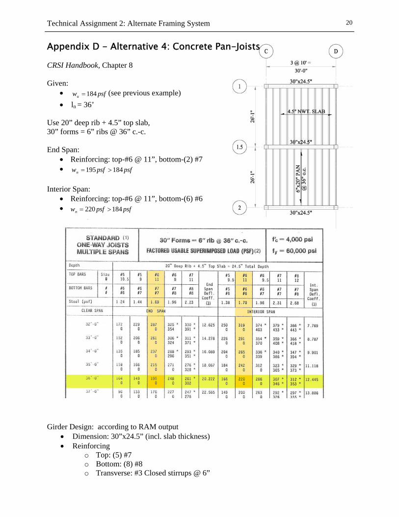
Appendix D - Alternative 4: Concrete Pan-Joists CRSI Handbook, Chapter 8 Given:
• psfwu 184= (see previous example) • ln = 36’
Use 20” deep rib + 4.5” top slab, 30” forms = 6” ribs @ 36” c.-c. End Span:
• Reinforcing: top-#6 @ 11”, bottom-(2) #7 • psfpsfwn 184195 >=
Interior Span:
• Reinforcing: top-#6 @ 11”, bottom-(6) #6 • psfpsfwn 184220 >=
Girder Design: according to RAM output
• Dimension: 30”x24.5” (incl. slab thickness) • Reinforcing
o Top: (5) #7 o Bottom: (8) #8 o Transverse: #3 Closed stirrups @ 6”
Technical Assignment 2: Alternate Framing System
21
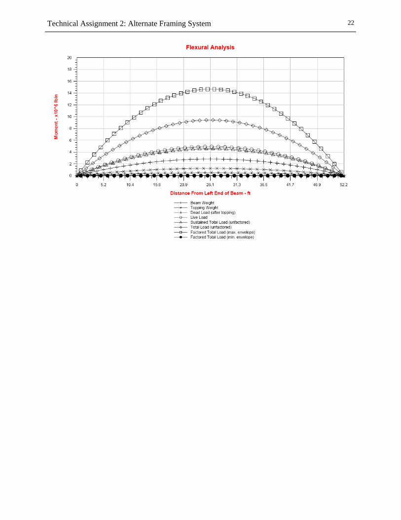
Appendix E - Alternative 5: Pre-cast, Prestressed Concrete System Beam Design Input:
Design:
Technical Assignment 2: Alternate Framing System
22
Technical Assignment 2: Alternate Framing System
23
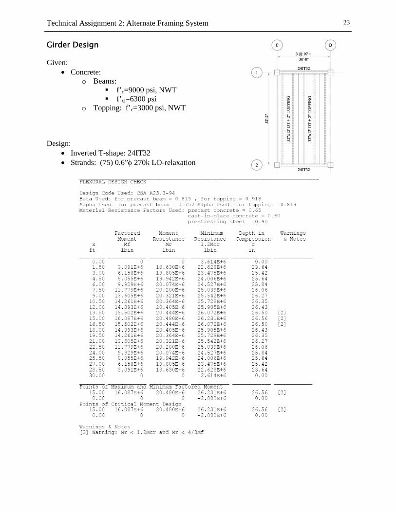
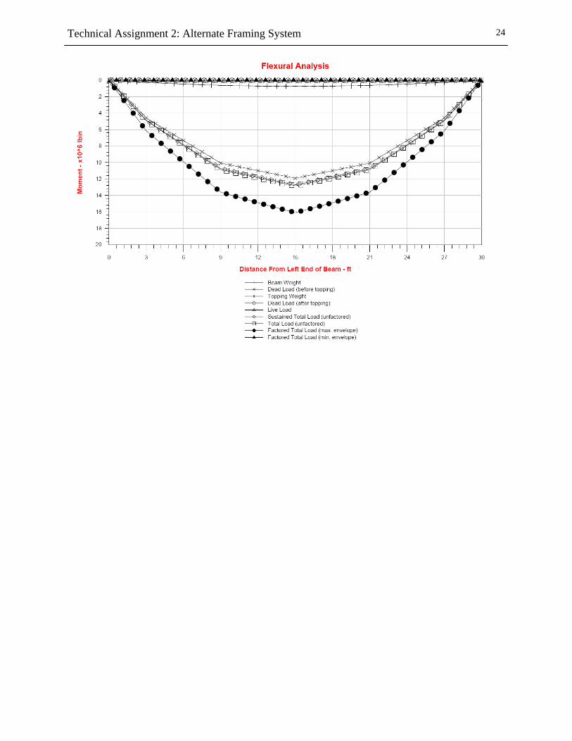
Girder Design Given:
• Concrete: o Beams:
f’c=9000 psi, NWT f’ci=6300 psi
o Topping: f’c=3000 psi, NWT Design:
• Inverted T-shape: 24IT32 • Strands: (75) 0.6”φ 270k LO-relaxation
Technical Assignment 2: Alternate Framing System
24
Technical Assignment 2: Alternate Framing System
25
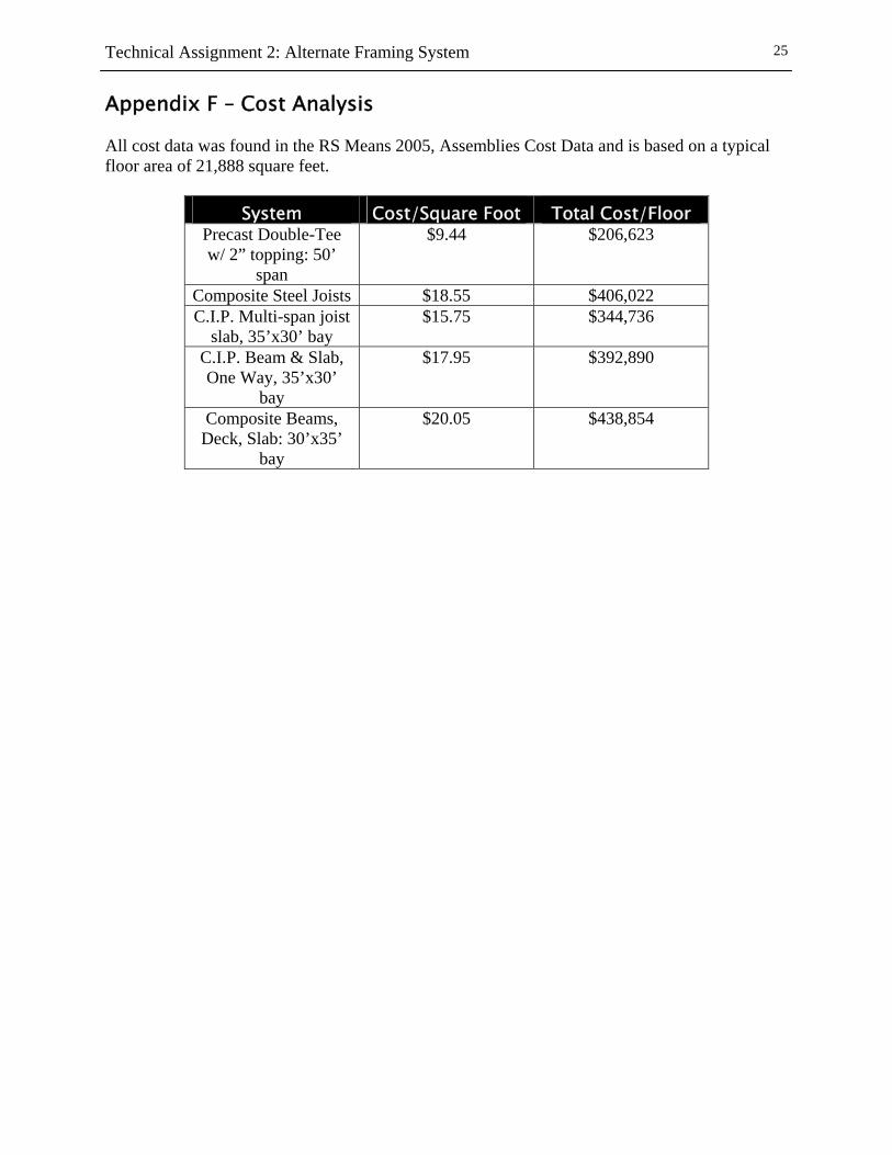
Appendix F – Cost Analysis All cost data was found in the RS Means 2005, Assemblies Cost Data and is based on a typical floor area of 21,888 square feet.
System Cost/Square Foot Total Cost/Floor Precast Double-Tee w/ 2” topping: 50’
span
$9.44 $206,623
Composite Steel Joists $18.55 $406,022 C.I.P. Multi-span joist
slab, 35’x30’ bay $15.75 $344,736
C.I.P. Beam & Slab, One Way, 35’x30’
bay
$17.95 $392,890
Composite Beams, Deck, Slab: 30’x35’
bay
$20.05 $438,854
Technical Assignment 2: Alternate Framing System
26
Appendix G – Framing Plans