Embed Size (px)
Citation preview

. - - - - N A S A TECHNICAL NOTE N A S A TN D-3583
= +" - 0e3 e,/ -I 00 - r lh 0-
I+= = T w- * n 0- = e= 4 z - * x c LOAN COPY: RET1 3B" -4 AFWL (WLIL. Ew z KIRTLAND AFB, r
GROUND EFFECTS RELATED TO LANDING OF AIRPLANES WlTH LOW-ASPECT-RATIO WINGS
by WiZZium B. Kemp, Jr., Vernurd E. Lockwood, und W. Pelhum PhiZZips
Lungley Reseurch Center LungZey Stution, Humpton, Va.
N A T I O N A L A E R O N A U T I C S A N D SPACE A D M I N I S T R A T I O N O C T O B E R 1966
f
https://ntrs.nasa.gov/search.jsp?R=19660028848 2020-02-29T22:27:40+00:00Z

TECH LIBRARY KAFB,NM
I111111111111111111111 IIIIIllllllllll11llIll1
GROUND EFFECTS RELATED TO LANDING OF AIRPLANES
WITH LOW-ASPECT-RATIO WINGS
By William B. Kemp, Jr., Vernard E. Lockwood, and W. Pelham Phillips
Langley Research Center Langley Station, Hampton, Va.
NATIONAL AERONAUTICS AND SPACE ADMINISTRATION
For sale by the Clearinghouse far Federal Scientific and Technical Information Springfield, Virginia 22151 - Price $1.00

GROUND EFFECTS RELATED TO LANDING OF AIRPLANES
WITH LOW-ASPECT-RATIOWINGS'
By William B. Kemp, Jr., Vernard E. Lockwood, and W. Pelham Phillips Langley Research Center
SUMMARY
Some results of a study of the influence of ground-induced aerodynamic effects on the landing maneuver of airplanes with low-aspect-ratiowings are presented. The fundamental mechanism of ground induction is reviewed and a simplified landing-flare analysis is used to illustrate the significance of the ground-induced pitching moment, the load factor just before touchdown, and the ground effects on the elevator characteristics. Some effects of wing planform and airplane size are shown by use of dynamic calculations of airplane motions during the landing flare. A constant-pitchattitude landing flare is shown to be possible for some large airplanes with low-aspect-ratio wings.
INTRODUCTION
Many airplane designs proposed for supersonic missions have employedlow-aspect-ratiodelta-related wing planforms. The achievement of appropriate lift coefficients for landing with these wings requires angles of attack so high that provision of adequate ground clearance is a serious problem and may possibly necessitate lower wing loadings or longer landing gears than would be desirable otherwise. Some wind-tunnel measurements on low-aspect-ratiowings have indicated that the effects of ground proximity may allow the angle of attack at a landing touchdown to be several degreesless than that required to obtain the same lift coefficient away from the ground, and thus may significantly alleviate the ground.-clearanceproblem. Furthermore, since this angle-of-attack change due to ground proximity may be of the same order of magnitude as the flight-path angle in a normal landing approach, the execution of a landing-flare maneuver without changing airplane attitude appears within the realm of possibility. The constant-attitude flare is viewed in some quarters as being considerably easier and therefore safer than a conventional landing-flare maneuver.
With these considerations in view, a study has been initiated at the NASA Langley Research Center using wind-tunnel experiments and analytical procedures to determine the influence of several configuration parameters on the ground effects on low-aspect-ratio wings. It is the purpose of this paper to present some highlights of the findings to date as they relate to the landing maneuver.
lpresented at the classified "Conference on Aircraft Aerodynamics," Langley Research Center, May 23-25, 1966, and published in NASA SP-124.

SYMBOLS
A
I
C
h
hh3
n
S
t
V
W
a
6
Mi,G
h F
B F
Y
9
A
2
wing aspect ratio
wing mean aerodynamic chord, ft
elevator chord, ft
lift coefficient
drag coefficient
pitching-moment coefficient
rate of change of lift coefficient with elevator angle at constant angle of attack, per degree
rate of change of pitching-moment coefficient with elevator angle at constant angle of attack, per degree
height above ground of a point on the wing chord plane at the longitudinal location of the center of gravity, ft
height of landing gear above ground, ft
normal load factor
wing area, sq ft
time, sec
airplane velocity, knots
airplane weight, lb
angle of attack, deg
elevator angle, deg
ground-induced increment in any coefficient Ci
angle-of-attack change during the flare, deg
elevator-angle change during the flare, deg
flight-path angle, deg
airplane pitch attitude, deg
leading-edge sweepback angle, deg

Subscripts:
A conditions in free-air approach
G conditions at ground contact
DISCUSSION
Comparison of Conventional- and Delta-Wing Airplanes
The first two figures compare the ground effects on two airplane configurations having widely different aspect ratios. Figure 1 illustrates the ground effects measured on a wind-tunnel model typical of a conventional subsonic jet transport with an aspect-ratio-6wing. Drag coefficient, angle of attack, and pitching-moment coefficient are shown as functions of lift coefficient. The solid curves represent the characteristics in free air and the dashed curves correspond to the wheels touching the ground. The data of figure lwere obtained with a tail incidence of -6O relative to the wing chord plane and a trailing-edge flap deflection of 600. The flap was designed for use with blowing at the slot lip but the data of figure 1 were measured without blowing, and thus the maximum lift coefficient is lower than would be expected from a flap system designed for use without blowing.
At the lower lift coefficients, the ground effect produces a small increase in lift at a given angle of attack. The maximum lift coefficient, however, is significantly reduced by proximity to the ground. These trends are typical Of the ground effects observed on configurations with wings of moderate to high aspect ratio. For comparison, figure 2 shows the corresponding characteristics of a tailless model having a 55' clipped delta wing with an aspect ratio of 2.26 with no twist, camber, or flap deflection. Again, the drag coefficient, angle of attack, and pitching-moment coefficient are plotted against lift coefficient for free air and for a height representative of a wheel touchdown condition. Since the low-aspect-ratiowing does not exhibit a true stall, the ground effects on maximum lift coefficient need not be considered. Lift coefficients appropriate for a landing approach are indicated for each configuration. Observe that at the approach lift coefficient, the ground effects on the low-aspect-ratiowing allow a reduction in angle of attack of more than 3O from free air to touchdown, whereas the corresponding angle-of-attack reduction for the subsonic jet configuration is only about 1/2O.
Both configurations show significant drag reductions in ground effect. Although these drag reductions would affect the speed bleed-off in a landing flare, further analysis of the ground effects on drag is beyond the scope of this paper.
The pitching-moment characteristics show that both configurations experience a modest increase in static stability in proximity to the ground, with a resultant increase in nose-down moment at the approach lift coefficient. The
3

effect of trimming out this moment change is discussed in a subsequent section. The data of figures 1 and 2 show that the angle-of-attack increment produced by ground proximity is of greatest interest for the low-aspect-ratio configuration. The present study has, therefore, emphasized the low aspect ratios.
Mechanism of Ground Induction
Consider an airplane flying in close proximity to the ground (fig. 3 ) . The effect of the ground is to prevent the existence of any vertical air velocity at the ground plane. If the ground is replaced by an inverted mirror-image airplane flying under the ground, all vertical velocities induced by the airplane and its image are canceled at the plane of symmetry. Thus, the effects of the image airplane are identical to the effects of a ground plane. Figure 4 shows the airplane in side view with a typical chordwise distribution of lift due to angle of attack. The aerodynamic center is at the centroid of this distribution. This same distribution of lift is represented on the image airplane as a system of lifting and trailing vortices. The image vortex system induces upwash velocities in the wing chord plane that may be distributed somewhat as shown in the middle sketch. The induced upwash over the region of the wing has an average value which is equivalent to an angle-of-attackchange and a gradient which is equivalent to a camber change. The equivalent camber would induce a lift whose center would be near the rear of the wing. The combined ground-induced lift may be distributed as shown by the lower sketch and its center of pressure would be expected to lie behind the aerodynamic center and produce a nose-down ground-induced pitching moment.
Experimental Program
The experimental program recognized the importance of the ground-induced pitching moment by placing some emphasis on the configuration of the elevators used to trim out the moment. Figure 5 illustrates two of the wind-tunnel models used. The wings were of delta planform with clipped tips and had leading-edge sweep angles of 55' and 70'. Some data obtained on this '35' wing were shown in figure 2. Elevators having chords of about 10 percent and 20 percent of the wing mean aerodynamic chord were examined. The models were tested in a wind tunnel at various heights above a ground plane. A moving-belt ground plane was used to remove uncertainties even though a correlation discussed in reference 1 indicates that the moving belt was unnecessary for these models.
The ground effects measured on these two models are compared in figure 6. The ground-induced increments in lift and pitching moment at zero elevator deflection, and the ground-induced increments in the elevator lift and moment parameters, are shown as functions of height above the ground. The ground-induced increments were measured at a constant angle of attack of 12O. The lift increment and the increments of the elevator parameters are each normalized by their respective free-air values.
4

For the 55' wing, shown by the solid curves, all of the parameters increase continuously with decreasing height. For the 700 wing, the lift at zero elevator and the lift due to elevator deflection also increase continuously but the two moment parameters show a reversal in the ground-effect trend at the lowest height. Although this trend reversal is not fully understood at present, it may be associated with the formation of an effective venturi throat between the ground and the wing trailing edge that may cause negative pressures on the underside of the wing near the trailing edge. It is possible that the 55' wing may also have shown some tendency toward trend reversal if it had been tested closer to the ground. The lowest points shown for each wing, however, represent heights that are appropriate for wheel touchdown. The ground-induced lift increment at touchdown is seen to be nearly the same for both wings.
Simplified Landing-Flare Analysis
In order to assess the importance of these ground effects on the landing maneuver, the analysis procedure illustrated in figure 7was used. Two flight conditions are assumed. The first is a steady-state landing approach glide out of ground effect on a straight descending flight path. The second represents the conditions at the instant of wheel contact with the ground. The flight path here may be curved end is usually at a flight-path angle less than that in the approach.
The curvature of the flight path requires a normal load factor somewhat greater than 1. The normal load factor at ground contact may be expressed approximately as the ratio of the lift coefficient at ground contact to that in the steady-state approach. Now if the approach lift coefficient is known and a value for normal load factor is assumed, the lift coefficient at ground contact may be determined. The wind-tunnel data may then be used to find the trimmed angle of attack in the approach and at ground contact corresponding to the appropriate lift coefficients and ground heights. The change in angle of attack during the flare is denoted by the symbol LhLF and is a s'ortof ground-effect figure of merit as determined in the wind tunnel.
The significance of this parameter is indicated by the second equationof figure 7,which was derived by using the angle relationships shown in the sketches. For a smooth landing, the flight-path angle at ground contact should be nearly zero. Thus, for any given value of the approach flight-path angle, the change in airplane attitude required to achieve this change in flight-path-
angle is determined by LaF. If, for example, the value of AUF were - 2 ~lo, a very reasonable landing flare could be achieved with no change in airplaneattitude. The change in elevator angle during the flare can also be determined from the wind-tunnel data and is a measure of the required pilot activity.
Application of this analysis procedure to the data for the 5 5 O delta wingyields the results given in figure 8. The angle-of-attack increment &F and the corresponding increment in elevator angle are given as functions of the approach lift coefficient with the normal load factor at ground contact as a
5
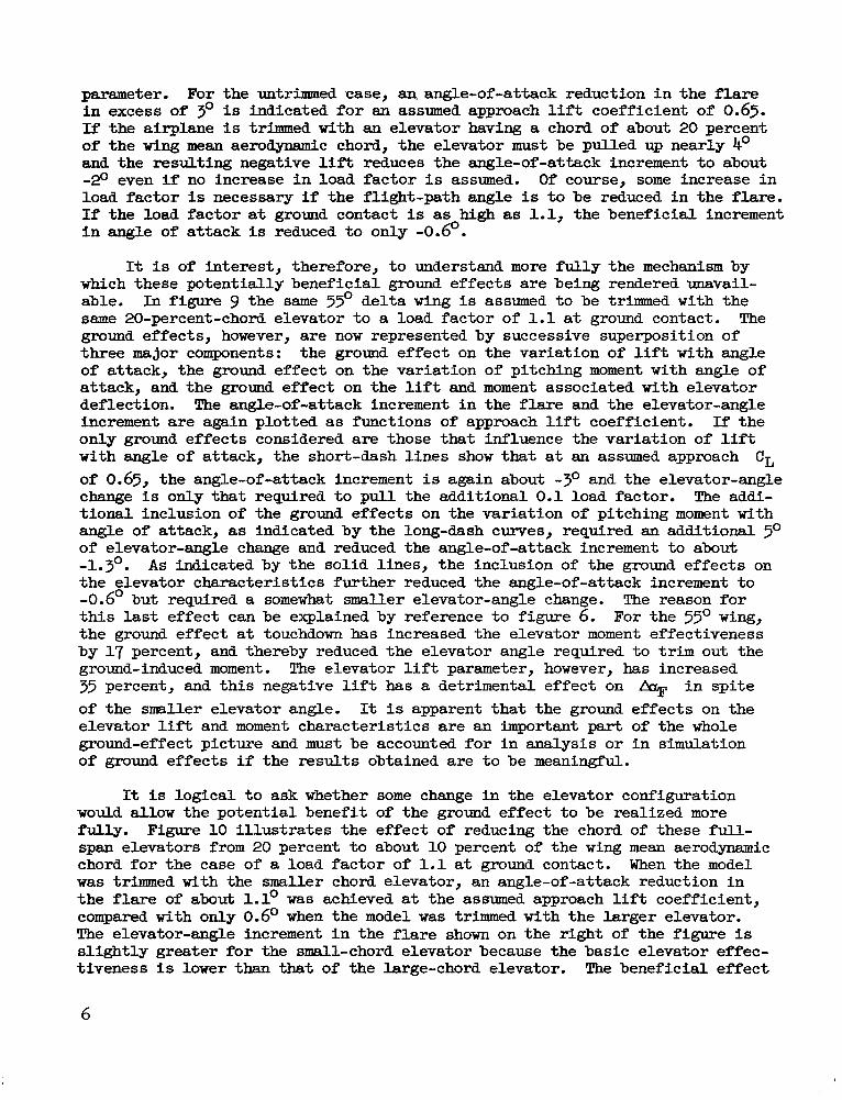
parameter. For the untrimmed case, anangle-of-attackreduction in the flare in excess of 3' is indicated for an assumed approach lift coefficient of 0.65. If the airplane is trimmed with an elevator having a chord of about 20 percent of the wing mean aerodynamic chord, the elevator must be pulled up nearly 4' and the resulting negative lift reduces the angle-of-attack increment to about -20 even if no increase in load factor is assumed. Of course, some increase in load factor is necessary if the flight-path angle is to be reduced in the flare. If the load factor at ground contact is as high as 1.1,the beneficial increment in angle of attack is reduced to only -0.6'.
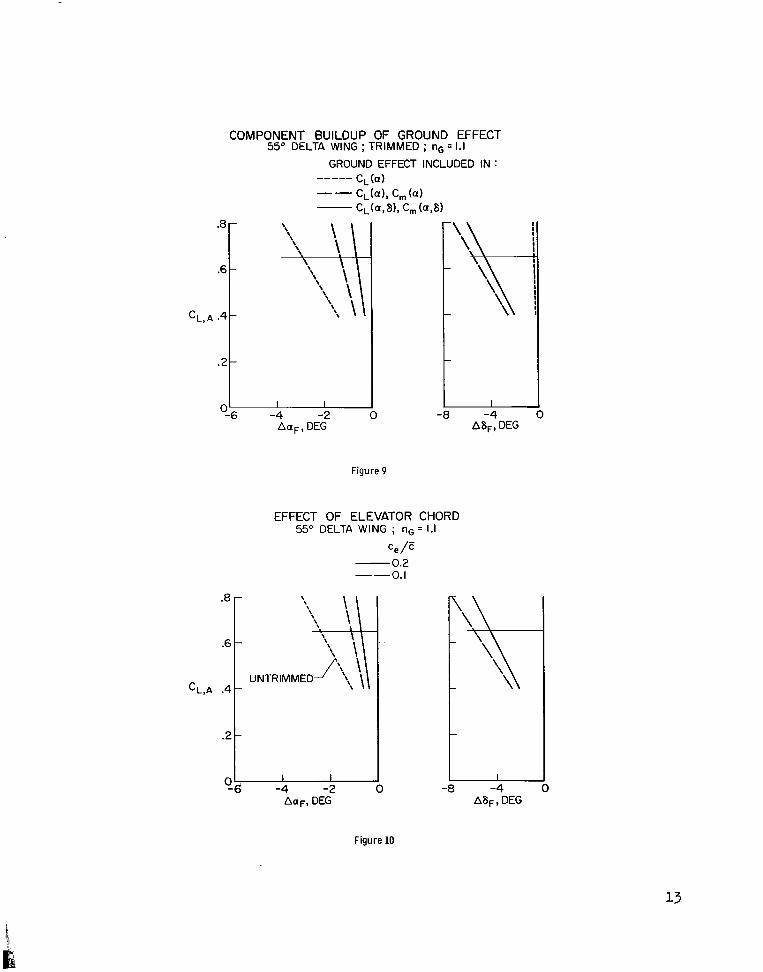
It is of interest, therefore, to understand more fully the mechanism by which these potentially beneficial ground effects are being rendered unavailable. In figure 9 the same 55' delta wing is assumed to be trimmed with the same 20-percent-chord elevator to a load factor of 1.1at ground contact. The ground effects, however, are now represented by successive superposition of three major components: the ground effect on the variation of lift with angle of attack, the ground effect on the variation of pitching moment with angle of attack, and the ground effect on the lift and moment associated with elevator deflection. The angle-of-attack increment in the flare and the elevator-angle increment are again plotted as functions of approach lift coefficient. If the only ground effects considered are those that influence the variation of lift with angle of attack, the short-dash lines show that at an assumed approach CL of 0.65, the angle-of-attack increment is again about -3O and the elevator-angle change is only that required to pull the additional 0.1load factor. The additional inclusion of the ground effects on the variation of pitching moment with angle of attack, as indicated by the long-dash curves, required an additional 5O of elevator-angle change and reduced the angle-of-attack increment to about -1.3'. As indicated by the solid lines, the inclusion of the ground effects on the elevator characteristics further reduced the angle-of-attack increment to -0.6' but required a somewhat smaller elevator-angle change. The reason for this last effect can be explained by reference to figure 6. For the 35O wing, the ground effect at touchdown has increased the elevator moment effectiveness by 17 percent, and thereby reduced the elevator angle required to trim out the ground-induced moment. The elevator lift parameter, however, has increased 35 percent, and this negative lift has a detrimental effect on % in spite of the smaller elevator angle. It is apparent that the ground effects on the elevator lift and moment characteristics are an Fmportant part of the whole ground-effect picture and must be accounted for in analysis or in simulation of ground effects if the results obtained are to be meaningful.
It is logical to ask whether some change in the elevator configuration would allow the potential benefit of the ground effect to be realized more fully. Figure 10 illustrates the effect of reducing the chord of these full-span elevators from 20 percent to about 10 percent of the wing mean aerodynamic chord for the case of a load factor of 1.1 at ground contact. When the model was trimmed with the smaller chord elevator, an angle-of-attack reduction in the flare of about 1.1' was achieved at the assumed approach lift coefficient, compared with only 0.6~when the model was trimmed with the larger elevator. The elevator-angle increment in the flare shown on the right of the figure is slightly greater for the small-chord elevator because the basic elevator effectiveness is lower than that of the large-chord elevator. The beneficial effect
6
of reducing elevator chord i s due pa r t ly t o the longer moment arm of the small elevator which allows a given moment change t o be trimmed out with l e s s l o s s i n l i f t , and par t ly t o the more rearward location of the center of pressure of the ground-induced l i f t associated with elevator deflection.
CL, GThe assumption that I-Q = -, stated on figure 7 and used i n figures 8
CL,A t o 10, ignores not only any changes i n speed but a l so the e f fec t of the component of engine thrus t acting normal t o the f l i g h t path. It i s c lear t ha t t h i s th rus t e f fec t is detrimental t o f l a r e performance i f the ground effects allow an angle of attack reduction i n the f l a r e . The following expression f o r load factor a t ground contact accounts f o r t h i s thrust effect , assuming that the thrus t required f o r equilibrium i n the steady-state approach i s held constant during the flare :
Application of t h i s expression t o the data analyzed i n figures 8 t o 10 would resu l t i n values of IIG somewhat less than those s ta ted i n the figures.
Dynamic Mot ion Calculations
In the preceding discussion, the ground ef fec ts have been examined by comparing the i n i t i a l and f i n a l conditions i n a landing f l a r e with an assumed value f o r the touchdown load factor. The actual load factor can be determined from calculations using the dynamic equations of motion through complete landing-f l a r e maneuvers. Several examples of such calculations are given i n figure 11. This f igure presents the variation of r a t e of descent, elevator angle, and normal load factor with height of the landing gear above the ground, calculated f o r landing f l a r e s assumed t o be made a t constant pi tch a t t i tude and constant thrust . The e f fec ts of speed changes, which were negligible, and thrust orient a t ion were accounted f o r i n the calculation. For a l l cases the small-chord elevator, an approach speed of 131 knots, and an approach fl ight-path angle of -2.75O w e r e assumed. The f i r s t two curves compare the TO0 and 5 5 O wings on a i r planes having a wing area representative of a fixed-wing supersonic transport airplane. The wing loadings were selected t o give approach l i f t coefficients appropriate f o r the respective wing planforms. These airplanes first enter the ground-effect region a t a height of about 60 feet , and the ground effects reduce the rate of descent from an i n i t i a l value of 10.6 f e e t per second t o
1touchdown values of 5 f ee t per second f o r the TO0 wing and $ f e e t Per second for the 55O wing. Observe tha t although both airplanes reached about the same value of load fac tor a t touchdown, the load fac tor during most of the landing f l a r e w a s somewhat higher f o r the TO0 wing. This higher load fac tor resulted i n a greater reduction i n rate of descent.
7

The short-dash curves show a landing flare for an airplane assumed to be a 1/3-scale model of the large one with a 55' delta wing. The wing loading and the initial conditions are the same as those for the large airplane. The small airplane enters ground effect at a height of about 20 feet, and although the load factor reaches a peak value considerably higher than that for the large airplane, the high load factors exist for a much shorter duration and result in much less reduction in rate of descent. This finding implies that the importance of the ground effects on a large airplane cannot be directly inferred from observations made in flight of a small airplane.
The results shown here for the TO0 wing indicate a rate of descent at touchdown which is almost low enough for a smooth landing. The data used in these calculations were obtained on a wind-tunnel model without camber or twist. There are preliminary indications that wing twist in the direction of washout at the tips can provide further reductions in the rate of descent at touchdown. Thus, a successful constant-attitude landing flare can probably be achieved. Notice, however, that the elevator angle must be changed during the flare by about 7.Thus, an automatic flare - that is, one requiring no pilot action -has not been achieved.
CONCLUDING REMARKS
The study described has indicated that a meaningful analysis of wind-tunnel ground-effect data or a realistic simulation of ground effects must utilize a complete description of the ground effects on the lift and pitching-moment characteristics due to angle of attack and elevator deflection. In addition, it was shown that the ground effects on low-aspect-ratiowings can produce significantreductions in the pitch attitude at ground contact, and constant-attitude landing flares may be possible for some large airplane configurations. The truly automatic landing flare requiring no change in elevator angle, however, is difficult to achieve.
Langley Research Center, National Aeronautics and Space Administration,
Langley Station, Hampton, Va., May 24, 1966,126-13-03-22-23.
1. Turner, Thomas R.: Endless-Belt Technique f o r Ground Simulation. Conference on V/STOL and STOL Aircraft, NASA SP-116,1966,pp. 433-446.
,
8

GROUND EFFECT ON SUBSONIC JET TRANSPORT CONFIGURATION
A z 6
-FREE AIR --TOUCHDOWN (h /E = 0.65) 1.6
-1.4
-1.2
-1.0
-.a
.6- L II L I I I I 1 I I L -I--II 0 . I .2 .3 0 5 IO 15 .2 .I 0 -.I -.2
CD a , DEG Cm
Figure 1
GROUND EFFECT ON 55O DELTA CONFIGURATION A = 2.26~~
FREE AIR TOUCHDOWN ( h / E = 0.27)
APPROACH
/ 0l!z/ 5 10 15
a, DEG
Figure 2
9
CL

IMAGE REPRESENTATION OF GROUND
IMAGE AIRCRAFT
Figure 3
MECHANISM OF GROUND INDUCTION
AIRCRAFT
GROUND-INDUCED
GROUND-INDUCED LIFT
AERODYNAMICCENTER
I
Figure 4
10

MODELS USED IN WIND-TUNNEL INVESTIGATION
A = 2.26 A = 1.24
HINGE LINE
t 70°
I
Figure 5
GROUND EFFECT ON DELTA WINGS a.12"; ce=o.zc
A, DEG -55 -U- 70
b
k- \ a b
a -2 .4 0 -.02 -.04 -.06 0 .2 .4-.2 0 .2
LO(
.a
.6 WE
.4
.2
0 ACL,G Acm,G AcL8,G "m8, G
CL,A %,A Cm8,A
Figure 6
11

BASIS OF DATA ANALYSIS
"G =-CL, G
CL. A
APPROACH,FREE AIR
GROUND CONTACT
Figure 7
EFFECT OF TRIMMING AND FLARE LOAD FACTOR 55O DELTA WING ; c, z 0.2 F
-.8 \
.6- \
-CL, A .4
-.2
" -6 -4 -2 0 -8
L0-4
A a F ,DEG ASF, DEG
Figure 8
12
----- --
--
COMPONENT BUILDUP OF GROUND EFFECT
.8
.6
CL,A .4
.2
.8
.6
CL,A .4
.2
0
55" DELTA WING ;TRIMMED ; nG = 1.1 GROUND EFFECT INCLUDED IN :
c, (a) C,(a), c, (a ) C,(a,8), C,(a,8)
\'k\
1 -8 -4
A ~ F ,DEG
Figure 9
EFFECT OF ELEVATOR CHORD 55" DELTA WING ; nG 1.1
ce /E 0.2 0.I
\k -4 -2 0 -8 -4
AaF, DEG ASF, DEG
Figure 10

---
CONSTANT-ATTITUDE LANDING FLARES ce r~ 0.1E ;VA= 131 KNOTS ;YA= -2.75O
4 WING AREA, W/S, DEG SQ Fi LWSQ FT 70 8000 35 55 8000 40 55 889 40
-10 I - 8dh FT/SEC 6,DEG n dt
Figure 11
14 NASA-Langley, 1966 L-5265

“The aeronautical and Jpace activities of the United States shall be conducted so as to contribute . . . to the expansion of human knowledge of phenomena in the atmosphere and space. The Administration shall provide for the widest practicable and appropriate dissemination of information concerning its activities and the results thereof .”
AERONAUTICS-NATIONAL AND SPACEACTOF 1958
NASA SCIENTIFIC AND TECHNICAL PUBLICATIONS
TECHNICAL REPORTS: Scientificand technical information considered important, complete, and a lasting comribution to existing knowledge.
TECHNICAL NOTES: Information less broad in scope but nevertheless of importance as a contribution to existing knowledge.
TECHNICAL MEMORANDUMS: Information receiving limited distribution because of preliminary data, security classification, or other reasons.
CONTRACTOR REPORTS: Technical information generated in connection with a NASA contract or grant and released under NASA auspices.
TECHNICAL. TRANSLATIONS: Information published in a foreign language considered to merit NASA distribution in English.
TECHNICAL REPRINTS: Information derived from NASA activities and initially published in the form of journal articles.
SPECIAL PUBLICATIONS: Information derived from or of value to NASA activities but not necessarily reporting the results ,of individual NASA-programmed scientific efforts. Publications include conference proceedings, monographs, data compilations, handbooks, sourcebooks, and special bibliographies.
Details on the availability of these publications may be obtained from:
SCIENTIFIC AND TECHNICAL INFORMATION DIVISION
NATIONAL AERONAUTICS AND SPACE ADMINISTRATION
Washington, D.C. PO546