Embed Size (px)
Citation preview
WALL & CEILINGSOLUTIONS
gtekplasterboard.com.au
APRIL 2016 TECHNICAL BROCHURE
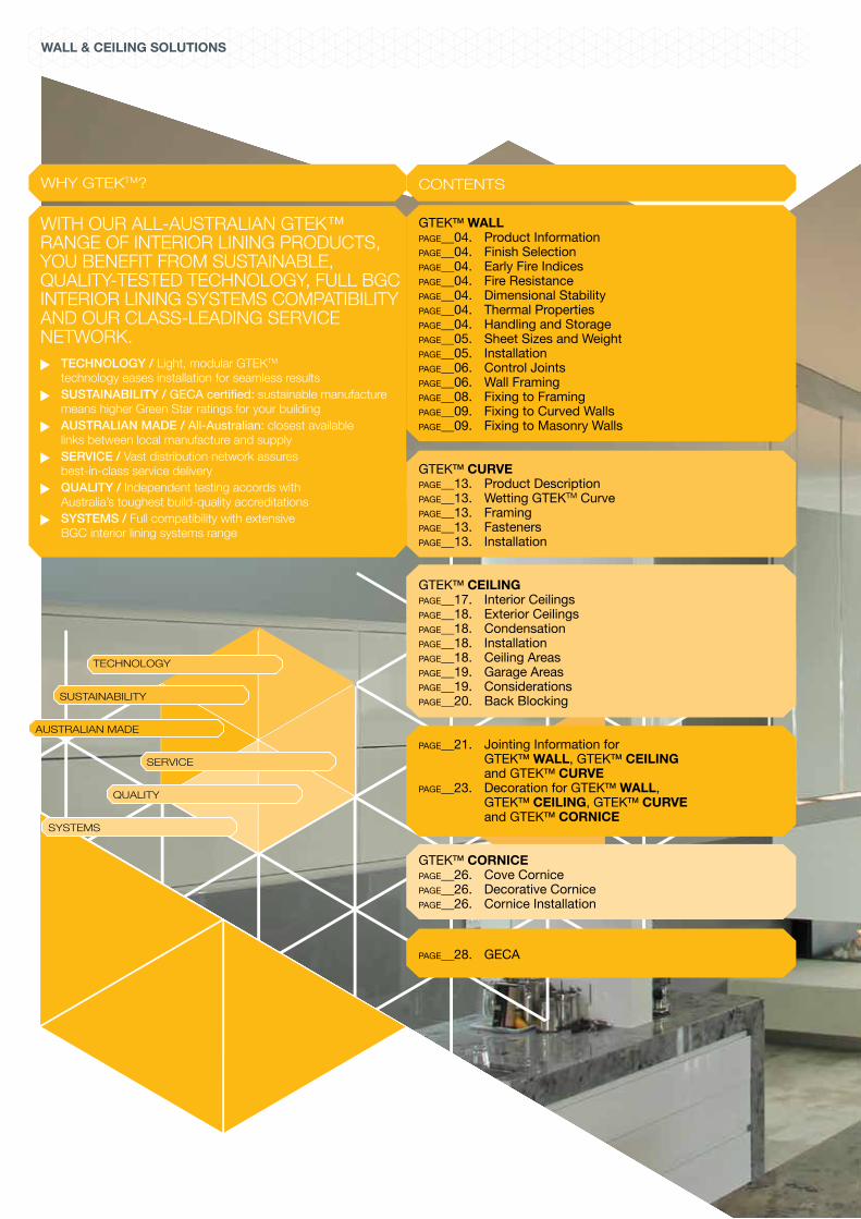
GTEKTM WALLGTEKTM CURVE GTEKTM CEILINGGTEKTM CORNICE
WALL & CEILING SOLUTIONS
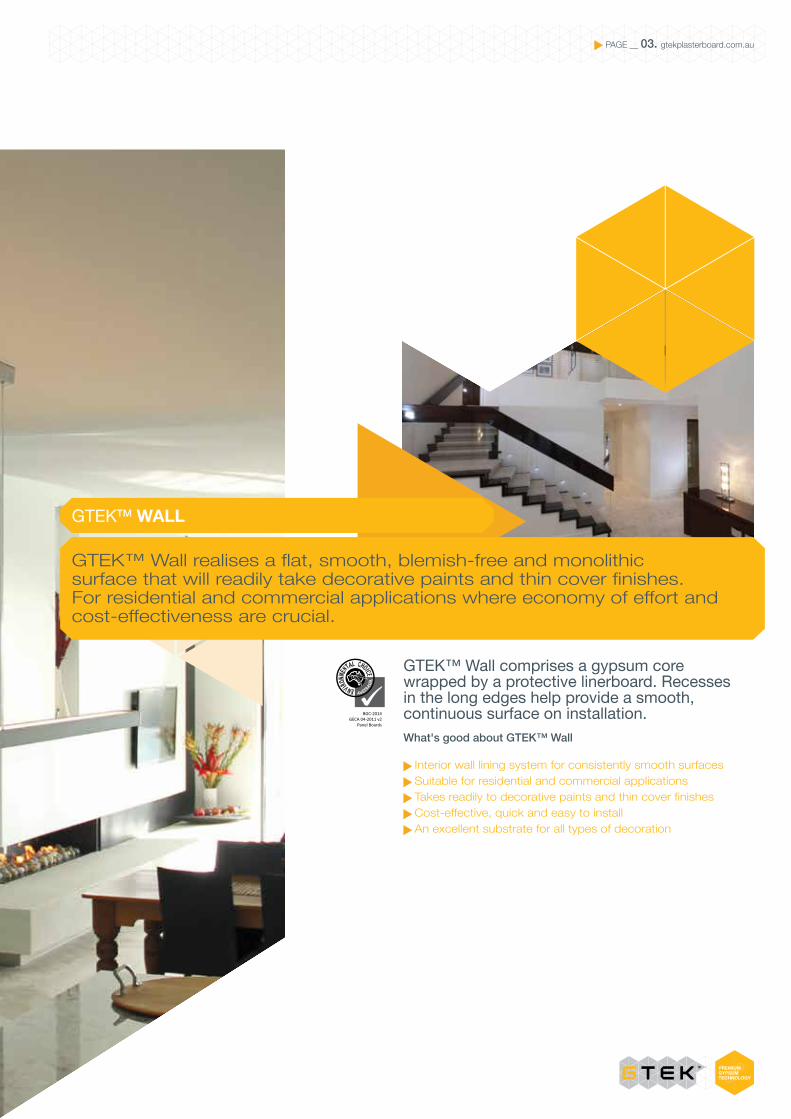
CONTENTS
GTEKTM WALLPAGE__04. Product InformationPAGE__04. Finish SelectionPAGE__04. Early Fire IndicesPAGE__04. Fire ResistancePAGE__04. Dimensional StabilityPAGE__04. Thermal PropertiesPAGE__04. Handling and StoragePAGE__05. Sheet Sizes and WeightPAGE__05. InstallationPAGE__06. Control JointsPAGE__06. Wall FramingPAGE__08. Fixing to FramingPAGE__09. Fixing to Curved WallsPAGE__09. Fixing to Masonry Walls
GTEKTM CURVEPAGE__13. Product DescriptionPAGE__13. Wetting GTEKTM CurvePAGE__13. FramingPAGE__13. FastenersPAGE__13. Installation
GTEKTM CEILINGPAGE__17. Interior CeilingsPAGE__18. Exterior CeilingsPAGE__18. CondensationPAGE__18. InstallationPAGE__18. Ceiling AreasPAGE__19. Garage AreasPAGE__19. ConsiderationsPAGE__20. Back Blocking
PAGE__21. Jointing Information for GTEKTM WALL, GTEKTM CEILING and GTEKTM CURVEPAGE__23. Decoration for GTEKTM WALL, GTEKTM CEILING, GTEKTM CURVE and GTEKTM CORNICE
GTEKTM CORNICEPAGE__26. Cove CornicePAGE__26. Decorative CornicePAGE__26. Cornice Installation
PAGE__28. GECA
WHY GTEKTM?
WITH OUR ALL-AUSTRALIAN GTEK™ RANGE OF INTERIOR LINING PRODUCTS, YOU BENEFIT FROM SUSTAINABLE, QUALITY-TESTED TECHNOLOGY, FULL BGC INTERIOR LINING SYSTEMS COMPATIBILITY AND OUR CLASS-LEADING SERVICE NETWORK.
TECHNOLOGY / Light, modular GTEKTM technology eases installation for seamless results
SUSTAINABILITY / GECA certified: sustainable manufacture means higher Green Star ratings for your building
AUSTRALIAN MADE / All-Australian: closest available links between local manufacture and supply
SERVICE / Vast distribution network assures best-in-class service delivery
QUALITY / Independent testing accords with Australia’s toughest build-quality accreditations
SYSTEMS / Full compatibility with extensive BGC interior lining systems range
SYSTEMS
AUSTRALIAN MADE
QUALITY
SUSTAINABILITY
SERVICE
TECHNOLOGY
GTEK™ Wall comprises a gypsum core wrapped by a protective linerboard. Recesses in the long edges help provide a smooth, continuous surface on installation. What's good about GTEK™ Wall
Interior wall lining system for consistently smooth surfaces Suitable for residential and commercial applications Takes readily to decorative paints and thin cover finishes Cost-effective, quick and easy to install An excellent substrate for all types of decoration
GTEK™ Wall realises a flat, smooth, blemish-free and monolithic surface that will readily take decorative paints and thin cover finishes. For residential and commercial applications where economy of effort and cost-effectiveness are crucial.
PAGE __ 03. gtekplasterboard.com.au
GTEKTM WALL
BGC-2014GECA 04-2011 v2
Panel Boards

GTEKTM WALL PAGE __ 04. gtekplasterboard.com.au
PRODUCT INFORMATION EARLY FIRE HAZARD INDICES
FIRE RESISTANCE
DIMENSIONAL STABILITY
THERMAL PROPERTIES
HANDLING AND STORAGE
FINISH SELECTION
GTEKTM Wall is purpose designed as a complete plasterboard wall and lining system, which complies with the requirements of the Building Code of Australia (BCA).
GTEKTM Wall interior lining provides a blemish free, monolithic, smooth surface ready for decorative paint and thin cover finishes for homes, offices and institutional buildings.
GTEKTM Wall is to be installed as detailed in AS 2589:2007 ‘Gypsum Linings – Application and Finishes’.
This manual is written to conform to the requirements of the Building Code of Australia (BCA) and AS 2589 Gypsum Linings - Applications and Finishes. Any deviations to these requirements can be made on the basis of an “alternate solution” as provided for by the BCA. Any “alternate solution” certifications must be provided by a certified practicing structural engineer and the responsibility for performance is then guaranteed by the engineer. Support framing must conform to the BCA and Australian Standards, be plumb, true and level, prior to the application of the plasterboard, see table 2 page 5. Refer to section 4.2.2 AS2589:2007
GTEKTM Wall may be fixed to timber or CFS (Cold-Formed Steel) light-steel framing or masonry, using plasterboard screws, nails and or adhesive.
Only screws or nails must be used for tiled areas and over existing lining or vapour barriers.
GTEKTM Wall has been tested by the NATA accredited AWTA for fire resistance in accordance with AS 1530.3; see Report Test Number: 7-518246-CN, April 2003.
Ignitability Index - 13 Spread of Flame Index - 0 Heat Evolved Index - 1 Smoke Developed Index - 3
Plasterboard is naturally fire resistant and is classified as non-com-bustible according to the Building Code of Australia (BCA) Section C1.12.
Plasterboard is dimensionally stable when compared to other building materials. Two measures of dimensional stability are:
Thermal coefficient of linear expansion (a) = 16.7 x 10⁻⁶ /˚C, measured unrestrained over the temperature range of 3˚C - 32˚C
Hygrometric coefficient of expansion 6.5 x 10⁻⁶ /%RH, measured unrestrained over the Relative Humidity (RH) range of 10% - 90%
The R value of plasterboard is a measure of its thermal insulation ability. Higher numbers indicate a better insulator. The ‘R’ values for plasterboard are:
10mm GTEKTM Wall = 0.05Km2/W 13mm GTEKTM Fire = 0.05Km2/W 16mm GTEKTM Fire = 0.06Km2/W
Plasterboard should be stacked flat, up off the ground and supported on level, equally spaced (max 450mm) gluts.
Care should be taken to ensure edges of the Plasterboard are not damaged when handling.
Plasterboard should be delivered to site immediately prior to installation to reduce the risk of damage.
As per AS/NZ2588 – The area to be lined or partitioned shall be protected from the weather and sufficiently dry to ensure that the fixed gypsum lining will not suffer subsequent deterioration due to moisture absorption.
Selecting the level of finish of the interior lining depends on the function of the space, lighting and the desired decorative surfaces required.
For most applications, Finish Levels 4 or 5 are used, as detailed in AS 2589:2007.
Level 3 is used, where heavy to medium texture finishes are applied and the lighting is non-critical.
Level 4 is most commonly used in commercial and residential work, where the finishes are satin, flat or low sheen paint systems and the lighting is non-critical.
For large area walls and ceilings, where critical and severe glancing lighting have an effect, a Level 5 finish must be used to minimise any adverse effects of harsh lighting.
GTEKTM WALL PAGE __ 05. gtekplasterboard.com.au
INSTALLATION
The cut edges should be sanded smooth to form clean joints.
When temporary fasteners are used to hold the plasterboard firmly against the framing members, they shall remain in place for a minimum of 24 hours under normal drying conditions.
Temporary fasteners may be fixed directly into the board or driven through gypsum plasterboard blocks or other methods of support that hold the board firmly against the framing members.
Fasteners are normally located so that they are separated from the positions of the daubs of adhesive. This may not be the case with temporary fasteners. Failure to remove temporary fasteners may result in the fasteners popping.
BGC Plasterboard recommends that this section should be read in conjunction with the architects’ specifications to determine the Level of Finishes.
GTEKTM Wall should be installed after all preceding trades have been completed.
Ceilings should be installed first. GTEKTM Ceiling should preferably be fixed with their long edges perpendicular to the windows or light sources, to obviate unwanted light reflections across the joints.
For the walls, GTEKTM Wall sheets should be laid with their long edges horizontal, to minimise the number of joints as well as light reflections across the joints. This is most important when Finish Levels 4 or 5 are specified, as indicated in Table 2 page 5.
GTEKTM Wall and Ceiling may be cut by scoring the face side and snapping back away from the score. Then cut the paper on the second side following the original score line. Neat straight cuts can be made using a straight edge.
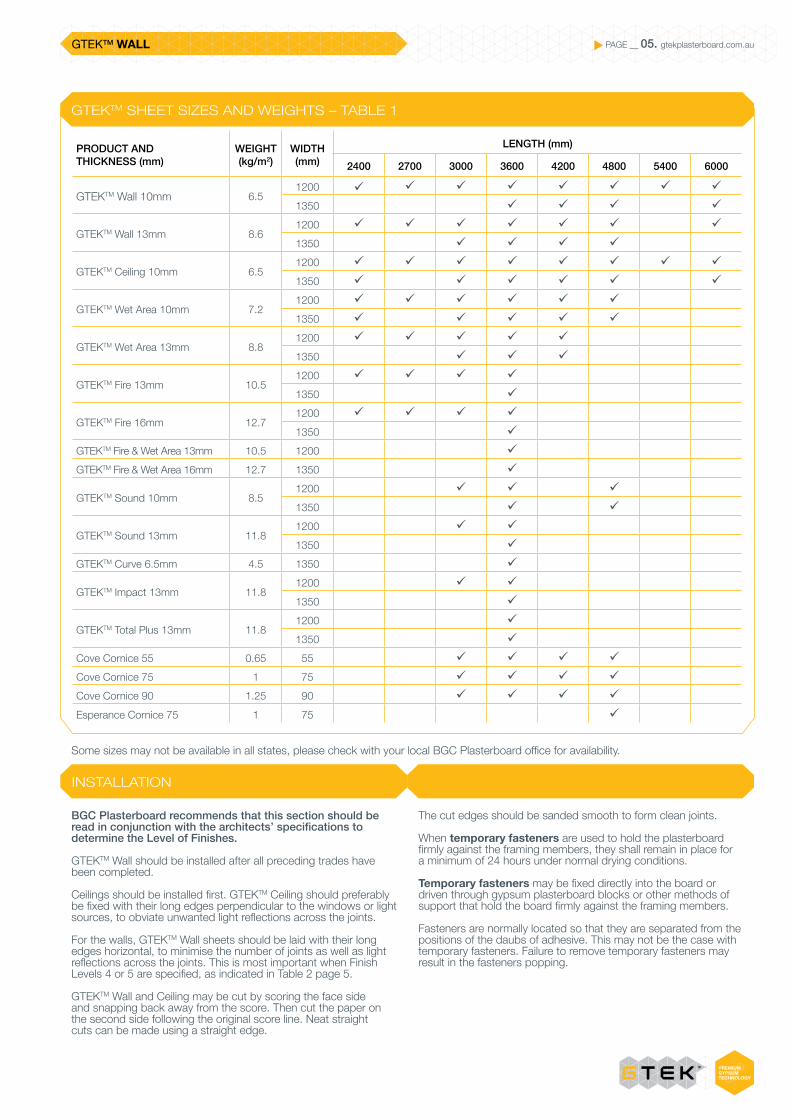
Some sizes may not be available in all states, please check with your local BGC Plasterboard office for availability.
GTEKTM SHEET SIZES AND WEIGHTS – TABLE 1
PRODUCT AND THICKNESS (mm)
WEIGHT (kg/m2)
WIDTH (mm)
LENGTH (mm)
2400 2700 3000 3600 4200 4800 5400 6000
GTEKTM Wall 10mm 6.51200 ü ü ü ü ü ü ü ü
1350 ü ü ü ü
GTEKTM Wall 13mm 8.61200 ü ü ü ü ü ü ü
1350 ü ü ü ü
GTEKTM Ceiling 10mm 6.51200 ü ü ü ü ü ü ü ü
1350 ü ü ü ü ü ü
GTEKTM Wet Area 10mm 7.21200 ü ü ü ü ü ü
1350 ü ü ü ü ü
GTEKTM Wet Area 13mm 8.81200 ü ü ü ü ü
1350 ü ü ü
GTEKTM Fire 13mm 10.51200 ü ü ü ü
1350 ü
GTEKTM Fire 16mm 12.71200 ü ü ü ü
1350 ü
GTEKTM Fire & Wet Area 13mm 10.5 1200 ü
GTEKTM Fire & Wet Area 16mm 12.7 1350 ü
GTEKTM Sound 10mm 8.51200 ü ü ü
1350 ü ü
GTEKTM Sound 13mm 11.81200 ü ü
1350 ü
GTEKTM Curve 6.5mm 4.5 1350 ü
GTEKTM Impact 13mm 11.81200 ü ü
1350 ü
GTEKTM Total Plus 13mm 11.81200 ü
1350 ü
Cove Cornice 55 0.65 55 ü ü ü ü
Cove Cornice 75 1 75 ü ü ü ü
Cove Cornice 90 1.25 90 ü ü ü ü
Esperance Cornice 75 1 75 ü

GTEKTM WALL PAGE __ 06. gtekplasterboard.com.au
CONTROL JOINTS
WALL FRAMING
AS/NZ 2589 states control joints shall be installed in walls and ceilings at a maximum spacing of 12m, or at control/ construction joints, whichever is the lesser.
External Ceilings are to be no greater than 6m spans.
Architectural features, openings, and the like may be used as control joint set out points.
Rondo ‘P35’ is suitable control/expansion joints.
Control joints are centrally located across the 15mm minimum gap between adjacent GTEKTM Wall sheets, and the flanges nailed at 300mm centres to the framing behind.
GTEKTM Wall may be fixed to timber, CFS light steel framing or furring channels, which satisfy the BCA requirements and which have been plumbed true and straight.
Timber framing must comply with the requirement of AS1684 ‘National Timber Framing Code’ and AS1720.1&.2 ‘Timber Structures’ and have a moisture content less than 16% at time of lining.
CFS light-steel framing must be in accordance with AS/NZS4600 ‘Cold-Formed Steel Structure Code’, AS3623 ‘Domestic Metal Framing’ and AS1397.
GTEKTM Wall may be fixed to CFS steel framing not exceeding 1.25mm BMT. Framing members must have a 35mm minimum face width for nail fixing and 32mm for screw fixing.
FIGURE 1 – CONTROL JOINT
FIGURE 2 – STEEL FRAME APPLICATION
GTEKTM Stud Adhesive daubs as per Table 4
Stud
Where butt joints occur, back block joint. Refer to back blocking page 18.
Top track
Framing member (joist, furring channel etc)
Additional framing member
Control joint
15mm max gap
Centre support screw at every second stud (temporary fastener)
GTEKTM Wall
Set sheets 6-10mm clear of floor

GTEKTM WALL PAGE __ 07. gtekplasterboard.com.au
WALL FRAMING
ADHESIVE, NAILS OR SCREWSFrames must be plumbed true and straight, to comply with the degree of finish required of the GTEKTM Wall.
The tolerance deviation over 1.8m spans, along and across members, for 90% of the wall and ceiling framing, shall be as set out in Table 2.
GTEKTM Wall may be fixed to the framing with either adhesive and nails or adhesive and screws as appropriate.
Water-based acrylic gypsum plaster adhesives such as GTEKTM Stud Adhesive, which comply with AS2753, are suitable for fixing GTEKTM Wall to both metal and timber framing.
Adhesive fixing is used in conjunction with fasteners, except for tiled areas, fire-rated construction, over vapour-barriers or existing work, where mechanical fasteners, nails or screws only must be used.
The position of daubs of GTEKTM Stud Adhesive ‘O’ and permanent fasteners ‘X’ should be as set out as shown in Table 4.
Ensure that contact surfaces are free from grease, oil, dust or other loose material prior to placing GTEKTM Stud Adhesive daubs (always clean down steel furring before fixing plasterboard sheeting).
Maximum spacing of framing members depends on the structural requirements for the building, in accordance with AS1170 and AS4055, however the maximum allowable spacing for studs, joists, furring channels or battens shall be as set out in the Table 3.
Trimmers are to be used where the main structural members change direction and all openings must be framed.
FRAME ALIGNMENT DEVIATION – TABLE 2
LEVEL 3 AND 4 LEVEL 5
Deviation of 90% of area
(mm)
Deviation of remaining area
(mm)
Deviation of 90% of area
(mm)
Deviation of remaining area
(mm)
4 5 3 4
POSITION AND NUMBER OF ADHESIVE DAUBS AND FASTENERS ACROSS SHEET – TABLE 4
MINIMUM NAIL FASTENER LENGTH – TABLE 5
SHEET WIDTH (mm)
WALL INTERNAL CEILINGS
GARAGE CEILINGS
EXTERIOR CEILINGS
Fasteners and Adhesive
1200 XOOOOX XOOXXOOX or XOXOXOX
XOXOXOX or XXXXX
XXXXX
1350 XOOOOOX XOOXXOOX or XOXOXOX
XOXOXOX or XXXXX
XXXXXX
Fasteners only
1200 XXXX XXXXX XXXXX XXXXX
1350 XXXXX XXXXXX XXXXX XXXXXX
THICKNESS (mm)
SUBSTRATE MATERIAL
HARDWOOD SOFTWOOD
10
2.8mm x 30mm galvanised nail or
2.8mm x 25mm ring shanked nail
2.8mm x 40mm galvanised nail or
2.8mm x 30mm ring shanked nail
13
2.8mm x 30mm galvanised nail or
2.8mm x 25mm ring shanked nail
2.8mm x 40mm galvanised nail or
2.8mm x 30mm ring shanked nail
16 2.8mm x 40mm galvanised nail
2.8mm x 50mm galvanised nail
SPACING OF FRAME MEMBER – TABLE 3
PRODUCT AND THICKNESS (mm) APPLICATION
MAX. SPACING OF FRAMING
MEMBER (mm)
GTEKTM Wall 10mmWalls 600
Ceilings 450
GTEKTM Wall 13mmWalls 600
Ceilings 600
GTEKTM Ceiling 10mmWalls 600
Ceilings 600
GTEKTM Wet Area 10mmWalls 600
Ceilings 450
GTEKTM Wet Area 13mmWalls 600
Ceilings 600
GTEKTM Fire 13mmWalls 600
Ceilings 600
GTEKTM Fire 16mmWalls 600
Ceilings 600
GTEKTM Fire & Wet Area 13mmWalls 600
Ceilings 600
GTEKTM Fire & Wet Area 16mmWalls 600
Ceilings 600
GTEKTM Sound 10mmWalls 600
Ceilings 450
GTEKTM Sound 13mmWalls 600
Ceilings 600
GTEKTM Impact 13mmWalls 600
Ceilings 600
GTEKTM Total Plus 13mmWalls 600
Ceilings 600
GTEKTM WALL PAGE __ 08. gtekplasterboard.com.au
WALL FRAMING
FIXING TO FRAMING
WALLS
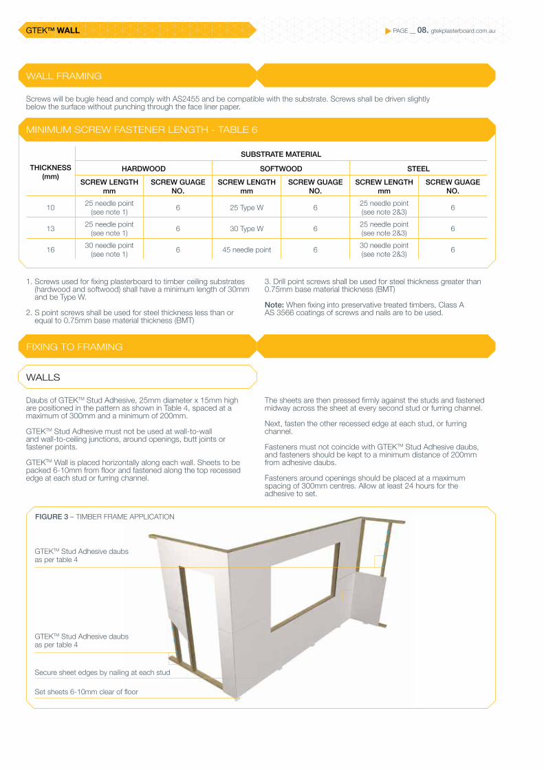
Screws will be bugle head and comply with AS2455 and be compatible with the substrate. Screws shall be driven slightly below the surface without punching through the face liner paper.
Daubs of GTEKTM Stud Adhesive, 25mm diameter x 15mm high are positioned in the pattern as shown in Table 4, spaced at a maximum of 300mm and a minimum of 200mm.
GTEKTM Stud Adhesive must not be used at wall-to-wall and wall-to-ceiling junctions, around openings, butt joints or fastener points.
GTEKTM Wall is placed horizontally along each wall. Sheets to be packed 6-10mm from floor and fastened along the top recessed edge at each stud or furring channel.
The sheets are then pressed firmly against the studs and fastened midway across the sheet at every second stud or furring channel.
Next, fasten the other recessed edge at each stud, or furring channel.
Fasteners must not coincide with GTEKTM Stud Adhesive daubs, and fasteners should be kept to a minimum distance of 200mm from adhesive daubs.
Fasteners around openings should be placed at a maximum spacing of 300mm centres. Allow at least 24 hours for the adhesive to set.
1. Screws used for fixing plasterboard to timber ceiling substrates (hardwood and softwood) shall have a minimum length of 30mm and be Type W.
2. S point screws shall be used for steel thickness less than or equal to 0.75mm base material thickness (BMT)
MINIMUM SCREW FASTENER LENGTH - TABLE 6
THICKNESS (mm)
SUBSTRATE MATERIAL
HARDWOOD SOFTWOOD STEEL
SCREW LENGTH mm
SCREW GUAGE NO.
SCREW LENGTH mm
SCREW GUAGE NO.
SCREW LENGTH mm
SCREW GUAGE NO.
10 25 needle point (see note 1) 6 25 Type W 6 25 needle point
(see note 2&3) 6
13 25 needle point (see note 1) 6 30 Type W 6 25 needle point
(see note 2&3) 6
16 30 needle point(see note 1) 6 45 needle point 6 30 needle point
(see note 2&3) 6
3. Drill point screws shall be used for steel thickness greater than 0.75mm base material thickness (BMT)
Note: When fixing into preservative treated timbers, Class A AS 3566 coatings of screws and nails are to be used.
FIGURE 3 – TIMBER FRAME APPLICATION
GTEKTM Stud Adhesive daubs as per table 4
Set sheets 6-10mm clear of floor
GTEKTM Stud Adhesive daubs as per table 4
Secure sheet edges by nailing at each stud

GTEKTM WALL PAGE __ 09. gtekplasterboard.com.au
FIXING TO CURVED WALLS
FIXING TO MASONRY WALLS
DESIGN CONSIDERATIONS
TRUE WALL SURFACES
INSTALLATION
GTEKTM Wall may be used on curved walls or ceilings where the radius is 900mm or greater.
If a tighter radius is required GTEKTM Curve is the ideal alternative.
Services should be installed prior to the GTEKTM Wall being fixed.
All wall fixtures MUST be fastened to the masonry wall. To prevent distortion of the plasterboard around the point of attachment:
(a) Apply additional daubs of GTEKTM Masonry Adhesive where the fixture is to be located.
(b) Locate metal spacers or ferrules between masonry wall and face of GTEKTM Wall.
(c) Fix packing pieces between masonry wall and back of GTEKTM Wall during installation. Control joints incorporated in a building to permit movement in the structure must be carried through all areas lined with GTEKTM Wall.
Surfaces are to be isolated from structural elements by installing control joints:
(a) When a GTEKTM Wall surface abuts any structural element or dissimilar wall assembly.
(b) In long wall runs, at not more than 12m centres.(c) Where control joints exist in masonry wall.
Basic wall systems are not to be used where they may be exposed to excessive moisture or humidity. Specific designs are available for bathroom and shower locations.
GTEKTM Wall is an alternative to solid plaster - not a means of isolating dampness.
All new masonry surfaces must be allowed to dry out to normal levels before installation of GTEKTM Wall. All contamination i.e. dust, release agents etc are to be removed to provide a suitable surface for adhesion.
When lining true wall surfaces, an allowance of about 5mm should be made for adhesive thickness (per side).
Masonry surfaces are to be firm, clean, dry and free of dust, oil, form release agents and curing compounds.
Establish the basis of a true wall plane before commencing installation. Levelling pads are to be used where irregularities in wall surface exceed 15mm.
GTEKTM Wall sheets can be fixed horizontally or vertically.
Daubs of GTEKTM Masonry Adhesive can be applied to the wall surface or to the back of the sheets.
Hold sheets in position until adhesive sets by using temporary masonry nails.
Framing Requirements
Ensure frames do not exceed maximum spacing recommendations.
Where tight radii are required ensure double studs are used at the end of the curve in order to prevent any deflection.
As an alternative to timber plates, Rondo manufactures and supplies a Flexi Track for the use and installation of studs. Refer to Rondo for more information.
Because GTEKTM Masonry Adhesive is a setting type cement, do not use mix after setting or hardening has commenced.
Mix only a sufficient quantity so that:
(a) The wall area prepared for lining at any time can be covered with one sheet of GTEKTM Wall.
(b) The GTEKTM Masonry Adhesive will maintain its working properties for the duration of the installation and final positioning of the sheets.
Check alignment of the wall with a straight edge to establish the wall alignment.
Strike a chalk line on ceiling and floor for use as a guide to align the face of the GTEKTM Wall.
If you intend to apply the daubs to the wall, mark the wall where the sheet edges fall to keep daubs 50mm away from the edges of the sheet.
Measure and cut the sheets to fit horizontally or vertically and stagger butt joints a minimum of 900mm.
Mix the GTEKTM Masonry Adhesive to a fairly thick consistency.
If the wall alignment is flat and true, using a 75mm broad knife, apply 50mm diameter daubs of adhesive, standing up a minimum of 15mm high, at not more than 50mm from all sheet edges and at 450mm maximum centres vertically and horizontally to the wall or to the back of the sheet. If the wall is out of alignment by up to 15mm, bigger daubs are recommended.
Additional daubs must be applied at butt joints, external angles and around power points, plumbing fixtures, doors, windows and skirtings.
Position boards and use a straightedge to tamp the boards into alignment both vertically and horizontally. Hold sheets in position for at least 80 to 100 minutes, to allow adhesive to set, by temporary masonry nails through sheet edges. If necessary, use temporary blocks in the field of the board.
Alternatively, if the wall alignment is flat and true, and a ‘solid wall’ effect is desired, apply GTEKTM. Masonry Adhesive over the entire board surface of the wall with a 10mm x 10mm notched trowel before positioning the sheet and aligning.

GTEKTM WALL PAGE __ 10. gtekplasterboard.com.au
FIGURE 4 – INSTALLATION TO MASONRY
FIXING TO MASONRY WALLS
IRREGULAR WALL SURFACES DIRECT ADHESIVE FIXING
Levelling pads are to be used where irregularities in the wall surface exceed 15mm.
Where the wall requires more than 25mm of packing to bring it back to a true line, a furring system should be used.
Irregular wall surfaces require straightening with a series of levelling pads, spaced to suit width of sheets.
Check the wall with string lines or straight edge to find high spots and use these as a guide for the level to be set.
Determine the true line for finished wall surface, and mark out GTEKTM Wall widths on the wall.
Position 75mm x 50mm alignment pads of GTEKTM Wall as illustrated, and attach to wall with GTEKTM Masonry Adhesive to a true line.
Space pads about 100mm from floor and at midpoints as illustrated. Alternatively, a 100mm wide GTEKTM Wall strip can be used at the skirting line.
Measure and cut sheets to fit horizontally or vertically.
Mix the GTEKTM Masonry Adhesive to a fairly thick consistency.
Apply 50mm diameter daubs of adhesive to the wall, standing up a minimum of 25mm high, at not more than 50mm from all sheet edges and at 450mm maximum centres vertically and horizontally.
Apply higher daubs where necessary.
Additional daubs must be applied at butt joints, external angles and around power points, plumbing fixtures, doors, windows and skirting.
Position boards and use a straight edge to press the boards back onto the levelling pads. Hold sheets in position for at least 80 to 100 minutes, to allow adhesive to set, by temporary masonry nails through sheet edges into the levelling pads. If necessary, use temporary blocks in the field of the board.
Sheets may be installed horizontally or vertically.
Ensure wall is:
Clean and dry Free from contaminants such as dust, oil or grease which will
prevent good bonding.
Using a good quality plaster based masonry adhesive, such as GTEKTM Masonry Adhesive, apply 50mm x 15mm high daubs of adhesive to the wall. Daubs must be applied at a maximum spacing of 450mm throughout the body of the sheet and less than 50mm from all sheet edges. It is recommended that the daubs be spaced at 200mm centres around the sheet edges, particularly if cornices or architraves are to be fitted.
Position the GTEKTM Wall sheets so that they are 6mm clear of the floor.
Press the GTEKTM Wall sheets into the adhesive, ensuring the sheet finishes flat and true; use of a straight edge is recommended.
Apply temporary restraints, either props or nails into the base wall mortar joints until the adhesive is dry – normally 24 hours. Nail the temporary restraints at about 600mm centres around the sheet perimeter and at about 1200mm centres in the body of the GTEKTM Wall.
Because GTEKTM Masonry Adhesive is a setting type cement, do not use mix after setting or hardening has commenced.
Mix only a sufficient quantity so that:
(a) The wall area prepared for lining at any time can be covered with one sheet of GTEKTMWall.
(b) The GTEKTM Masonry Adhesive will maintain its working properties for the duration of the installation and final positioning of the sheets.
Control joints should be installed:
To coincide with any movement control (expansion) joints in the structure.
At the junction of any dissimilar base wall type or construction. To break any continuous run of plasterboard greater than 4.2m.
GTEKTM Wall
Daubs of GTEKTM Masonry Adhesive 50mm diameter x 15mm thick
GTEKTM Masonry Adhesive daubs at 450mm max. in body of sheet
GTEKTM Masonry Adhesive at 200mm centres to sheet edges Set sheets 6mm above floor
Sheet fixed horizontally stagger end points
GTEKTM Masonry Adhesive daubs at 50mm max. from sheet
Set sheets 6-10mm clear of floor
GTEKTM WALL PAGE __ 11. gtekplasterboard.com.au
FIXING TO MASONRY WALLS
BATTENS AND FURRINGS
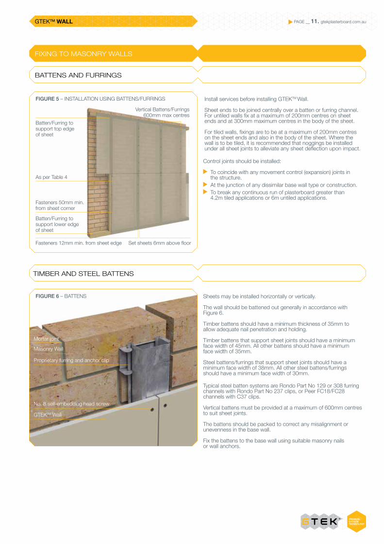
As per Table 4
Fasteners 12mm min. from sheet edge Set sheets 6mm above floor
Batten/Furring to support top edge of sheet
Batten/Furring to support lower edge of sheet
Fasteners 50mm min. from sheet corner
FIGURE 5 – INSTALLATION USING BATTENS/FURRINGS Install services before installing GTEKTM Wall.
Sheet ends to be joined centrally over a batten or furring channel. For untiled walls fix at a maximum of 200mm centres on sheet ends and at 300mm maximum centres in the body of the sheet.
For tiled walls, fixings are to be at a maximum of 200mm centres on the sheet ends and also in the body of the sheet. Where the wall is to be tiled, it is recommended that noggings be installed under all sheet joints to alleviate any sheet deflection upon impact.
Control joints should be installed:
To coincide with any movement control (expansion) joints in the structure.
At the junction of any dissimilar base wall type or construction. To break any continuous run of plasterboard greater than
4.2m tiled applications or 6m untiled applications.
TIMBER AND STEEL BATTENS
Sheets may be installed horizontally or vertically.
The wall should be battened out generally in accordance with Figure 6.
Timber battens should have a minimum thickness of 35mm to allow adequate nail penetration and holding.
Timber battens that support sheet joints should have a minimum face width of 45mm. All other battens should have a minimum face width of 35mm.
Steel battens/furrings that support sheet joints should have a minimum face width of 38mm. All other steel battens/furrings should have a minimum face width of 30mm.
Typical steel batten systems are Rondo Part No 129 or 308 furring channels with Rondo Part No 237 clips, or Peer FC18/FC28 channels with C37 clips.
Vertical battens must be provided at a maximum of 600mm centres to suit sheet joints.
The battens should be packed to correct any misalignment or unevenness in the base wall.
Fix the battens to the base wall using suitable masonry nails or wall anchors.
FIGURE 6 – BATTENS
Mortar joint
Masonry Wall
Proprietary furring and anchor clip
No. 8 self-embedding head screw
GTEKTM Wall
Vertical Battens/Furrings 600mm max centres
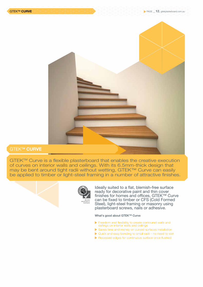
PAGE __ 12. gtekplasterboard.com.auGTEKTM CURVE
Ideally suited to a flat, blemish-free surface ready for decorative paint and thin cover finishes for homes and offices, GTEK™ Curve can be fixed to timber or CFS (Cold Formed Steel), light-steel framing or masonry using plasterboard screws, nails or adhesive.What's good about GTEK™ Curve
Freedom and flexibility to create contoured walls and ceilings on interior walls and ceilings
Saves time and money on curved surfaces installation Quick and easy bending to small radii – no need to wet Recessed edges for continuous surface once flushed
GTEKTM Curve is a flexible plasterboard that enables the creative execution of curves on interior walls and ceilings. With its 6.5mm-thick design that may be bent around tight radii without wetting, GTEK™ Curve can easily be applied to timber or light-steel framing in a number of attractive finishes.
GTEKTM CURVE
BGC-2014GECA 04-2011 v2
Panel Boards
PAGE __ 13. gtekplasterboard.com.auGTEKTM CURVE
PRODUCT DESCRIPTION
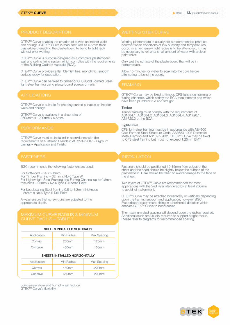
GTEKTM Curve enables the creation of curves on interior walls and ceilings. GTEKTM Curve is manufactured as 6.5mm thick plasterboard enabling the plasterboard to bend to tight radii without prior wetting.
GTEKTM Curve is purpose designed as a complete plasterboard wall and ceiling lining system which complies with the requirements of the Building Code of Australia (BCA).
GTEKTM Curve provides a flat, blemish free, monolithic, smooth surface ready for decoration.
GTEKTM Curve can be fixed to timber or CFS (Cold Formed Steel) light-steel framing using plasterboard screws or nails.
APPLICATIONS
GTEKTM Curve is suitable for creating curved surfaces on interior walls and ceilings.
GTEKTM Curve is available in a sheet size of 3600mm x 1200mm x 6.5mm.
PERFORMANCE
GTEKTM Curve must be installed in accordance with the requirements of Australian Standard AS 2589:2007 – Gypsum Linings – Application and Finish.
WETTING GTEK CURVE
Wetting plasterboard is usually not a recommended practice, however when conditions of low humidity and temperatures occur, or an extremely tight radius is to be attempted, it may be necessary to roll on a small amount of water with a clean paint roller.
Only wet the surface of the plasterboard that will be in compression.
Allow 15 minutes for water to soak into the core before attempting to bend the board.
FRAMING
GTEKTM Curve may be fixed to timber, CFS light-steel framing or furring channels, which satisfy the BCA requirements and which have been plumbed true and straight.
TimberTimber framing must comply with the requirements of AS1684.1, AS1684.2, AS1684.3, AS1684.4, AS1720.1, AS1720.2 or the BCA.
Light-SteelCFS light-steel framing must be in accordance with AS4600 Cold Formed Steel Structure Code, AS3623-1993 Domestic Metal Framing and AS1397-2001. GTEKTM Curve may be fixed to CFS steel framing but must not exceed 1.25mm BMT.
FASTENERS INSTALLATION
BGC recommends the following fasteners are used:
For Softwood – 25 x 2.8mm For Timber Framing – 32mm x No.6 Type W For Lightweight Steel Framing and Furring Channel up to 0.8mm thickness – 25mm x No.6 Type S Needle Point.
For Loadbearing Steel framing 0.8 to 1.2mm thickness – 25mm x No.6 Type S Drill Point
Always ensure that screw guns are adjusted to the appropriate depth.
Low temperature and humidity will reduce GTEKTM Curve's flexibility.
Fasteners should be positioned 10-15mm from edges of the sheet and the head should be slightly below the surface of the plasterboard. Care should be taken to avoid damage to the face of the sheet.
Two layers of GTEKTM Curve are recommended for most applications with the 2nd layer staggered by at least 200mm to avoid joint alignment.
GTEKTM Curve may be attached horizontally or vertically depending upon the framing support and application, however BGC Plasterboard recommend fixing in a horizontal direction which enables GTEKTM Curve to bend easier.
The maximum stud spacing will depend upon the radius required. Additional studs are usually required to support a tight radius. Please refer to diagrams for recommended spacing.
MAXIMUM CURVE RADIUS & MINIMUM CURVE RADIUS – TABLE 7
SHEETS INSTALLED VERTICALLY
Application Min Radius Max Spacing
Convex 250mm 125mm
Concave 450mm 150mm
SHEETS INSTALLED HORIZONTALLY
Application Min Radius Max Spacing
Convex 450mm 200mm
Concave 650mm 200mm

PAGE __ 14. gtekplasterboard.com.auGTEKTM CURVE
FIGURE 7 – VERTICAL FIX CONVEX - 1/3 SPACE METHOD
FIGURE 8 – HORIZONTAL FIX CONVEX
Fasten both layers at max. 100mm centres at start and finish of curve and at min. 200mm from edge of curve
Fasten both layers at max. 100mm centres at start and finish of curve and at min. 200mm from edge of curve
Recessed edge of second layer
Sheet bottom edge 6mm above finished floor level
Sheet bottom edge 6mm above finished floor level
No curve in this area
No curve in this area
Recessed edge of first layer
Recessed edge of second layer
First layer and second layer staggered a minimum 200mm to prevent aligned joints
Fasten both layers at top and bottom of sheets
Fasten both layers at top and bottom of sheets
100mm
100mm
200mm min.
200mm min.
125mm max.
200mm max.
Secure sheet edges by nailing at each stud
Convex curved area 250mm minimum radius
Convex curved area 450mm minimum radius
PAGE __ 15. gtekplasterboard.com.auGTEKTM CURVE
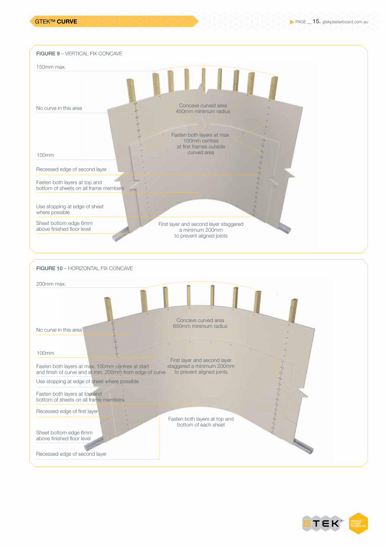
FIGURE 9 – VERTICAL FIX CONCAVE
FIGURE 10 – HORIZONTAL FIX CONCAVE
Concave curved area650mm minimum radius
Fasten both layers at top and bottom of sheets on all frame members
Fasten both layers at top and bottom of sheets on all frame members
Fasten both layers at max. 100mm centres at start and finish of curve and at min. 200mm from edge of curve
Recessed edge of second layer
Recessed edge of first layer
Recessed edge of second layer
Use stopping at edge of sheet where possible
Sheet bottom edge 6mm above finished floor level
Sheet bottom edge 6mm above finished floor level
Use stopping at edge of sheet where possible
Fasten both layers at max. 100mm centres
at first frames outside curved area
First layer and second layer staggered a minimum 200mm
to prevent aligned joints
Fasten both layers at top and bottom of each sheet
First layer and second layer staggered a minimum 200mm
to prevent aligned joints
No curve in this area
No curve in this area
150mm max.
200mm max.
100mm
100mm
Concave curved area450mm minimum radius
GTEKTM CEILING PAGE __ 16. gtekplasterboard.com.au
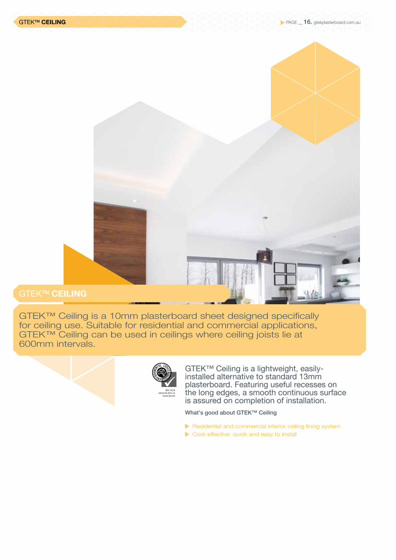
GTEK™ Ceiling is a lightweight, easily- installed alternative to standard 13mm plasterboard. Featuring useful recesses on the long edges, a smooth continuous surface is assured on completion of installation.What's good about GTEK™ Ceiling
Residential and commercial interior ceiling lining system Cost-effective: quick and easy to install
GTEK™ Ceiling is a 10mm plasterboard sheet designed specifically for ceiling use. Suitable for residential and commercial applications, GTEK™ Ceiling can be used in ceilings where ceiling joists lie at 600mm intervals.
GTEKTM CEILING
BGC-2014GECA 04-2011 v2
Panel Boards
PAGE __ 17. gtekplasterboard.com.auGTEKTM CEILING
INTERIOR CEILINGS
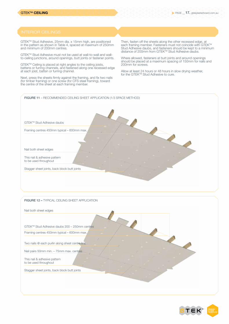
GTEKTM Stud Adhesive, 25mm dia. x 15mm high, are positioned in the pattern as shown in Table 4, spaced at maximum of 250mm and minimum of 200mm centres.
GTEKTM Stud Adhesive must not be used at wall-to-wall and wall-to-ceiling junctions, around openings, butt joints or fastener points.
GTEKTM Ceiling is placed at right angles to the ceiling joists, battens or furring channels, and fastened along one recessed edge at each joist, batten or furring channel.
Next, press the sheets firmly against the framing, and fix two nails (for timber framing) or one screw (for CFS steel framing), toward the centre of the sheet at each framing member.
Then, fasten off the sheets along the other recessed edge, at each framing member. Fasteners must not coincide with GTEKTM Stud Adhesive daubs, and fasteners should be kept to a minimum distance of 200mm from GTEKTM Stud Adhesive daubs.
Where allowed, fasteners at butt joints and around openings should be placed at a maximum spacing of 150mm for nails and 200mm for screws.
Allow at least 24 hours or 48 hours in slow drying weather, for the GTEKTM Stud Adhesive to cure.
FIGURE 11 – RECOMMENDED CEILING SHEET APPLICATION (1/3 SPACE METHOD)
FIGURE 12 – TYPICAL CEILING SHEET APPLICATION
GTEKTM Stud Adhesive daubs
GTEKTM Stud Adhesive daubs 200 – 250mm centres
Two nails @ each purlin along sheet centre line
Nail pairs 50mm min. – 75mm max. centres
Framing centres 450mm typical – 600mm max.
Framing centres 450mm typical – 600mm max.
This nail & adhesive pattern to be used throughout
This nail & adhesive pattern to be used throughout
Stagger sheet joints, back block butt joints
Stagger sheet joints, back block butt joints
Nail both sheet edges
Nail both sheet edges
GTEKTM CEILING PAGE __ 18. gtekplasterboard.com.au
EXTERNAL CEILINGS
In view of higher wind loadings and other influences on external ceilings, the industry has upgraded its specifications for these areas as follows:
Plasterboard is suitable for N1 and N2 wind zones only.
Framing members should be spaced at max 450mm centres. In areas where ceiling joists or roof trusses are spaced at more than 450mm, trimming or suitable ceiling battens should be provided at max. 450mm centres. Metal ceiling battens and furring channels should be installed in accordance with manufacturer’s specification.
Run plasterboard sheets at right angles to framing members. Provide a min 6mm gap between edges of the plasterboard sheet and adjacent walls, beams, columns and fascia’s.
Ceiling linings should be fully screw fixed at max 300mm centres, 32mm ‘W’ types screws should be used for fixing into timber framing. 25mm ‘S’ or ‘D’ type screws, as appropriate should be used for fixing into steel framing. External application corrosive resistant screws and protective coated angles should be used within coastal areas.
Back block all joints in ceiling linings as per back blocking specifications.
Control joints should be provided in external ceilings at max 6m centres in both directions.
External ceilings should be painted with a three coat external paint system in accordance with manufacturer’s recommendations.
Roof sarking and cross flow ventilations to the ceiling cavity can improve long term performance of external ceilings by reducing the possibility of condensation on top of the ceiling lining.
External ceilings require strict adherence to specification. Non-compliance will reflect in the finish.
CONDENSATION
Surface condensation and wind loads can be the main causes of lining board and jointing system failure. Insufficient protection can lead to the plasterboard distorting as well as potential mould attack.
Metal roofing is more susceptible to condensation build up than roofing tiles; if sarking or foil backed insulation is used under metal roofing ensure installation complies with the BCA and relevant Australian Standards.
It is important that ceiling cavity areas are well ventilated to prevent condensation build up. The installation of eave and gable vents, roof ventilatiors etc. can assist in this by providing permanent cross flow ventilation.
Building materials and systems may be adversely affected by these severe environmental and physical conditions, which if not installed correctly can lead to ceiling failure and or collapse.
INSTALLATION
CEILING AREAS
All perimeters must have appropriate framing/noggings etc. in order to support all sheet edges. Perimeters to be screw fixed only at 300mm centres. The perimeter may be fixed out with timber noggings, metal plasterers angle (Rondo P18) or equivalent.
Plasterboard sheets fixed to exterior ceilings must be mechanically fixed with appropriate screws at 300mm centres. Paper tape must be used in conjunction with setting type base products in the joins. Base and topping to comply with ASTM C475. Back block joints in accordance with AS/NZS 2589.
We have a range of Exterior Base and Topping compounds that are ideal for flushed joints on exterior walls and ceilings.
Plasterboard sheets to have a minimum 6-10mm space from perimeter walls.
Fascia boards/perimeter beams should continue at least 100mm below the bottom of the plasterboard ceiling or the perimeter wall/ceiling trim.
Framing centres to be at a maximum of 450mm.
Movement control (expansion) joints must occur at maximum distances of 6mtr x 6mtr in either direction.
Paint with a three coat exterior paint system applied to manufacturers’ recommendations.
RECOMMENDED GTEKTM
PLASTERBOARD MATERIALS
10mm GTEKTM Ceiling13mm GTEKTM Wall13mm GTEKTM Wet Area
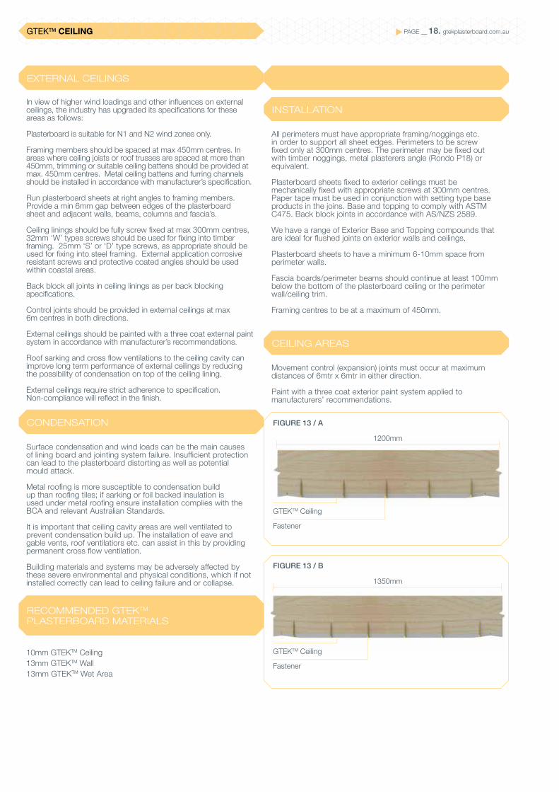
FIGURE 13 / A
FIGURE 13 / B
GTEKTM Ceiling
1200mm
1350mm
GTEKTM Ceiling
Fastener
Fastener
PAGE __ 19. gtekplasterboard.com.auGTEKTM CEILING
GARAGE CEILINGS
CONSIDERATIONS
Garage ceilings are subject to conditions that are more demanding than in any other part of the homes. This is the case even when garages are located under the same roof as the rest of the home. Garages have large doors that when open let in rain and strong wind, cars are garaged wet and these are not normally heated spaces. Garage doors also cause a large amount of constant vibration when in use that can affect board fixing and adhesion. These factors call for a more durable installation to avoid maintenance issues.
Installation requirements for Garage Ceilings:
Fix the ceiling sheets using the screw only method or the one third fixing method.
Provide additional framing around the perimeter by inserting trimmers between ceiling frames or installing a steel angle.
Fix the perimeter sheets using screws at 300mm max spacing.
Avoid windy conditions during and immediately after installation to ensure adhesives set intact.
Back block all plasterboard joints.
Roll or brush on a high quality sealer undercoat designed for exterior use and use a premium exterior paint system.
TABLE 8 – POSITION AND NUMBER OF ADHESIVE DAUBS AND FASTENEERS ACROSS SHEET
Before lining the building it is prudent to consider the following design and construction issues:
Consideration must be given to the framing, this may vary throughout Australia especially in high wind and coastal areas.
It is highly recommended to batten out the ceiling with Rondo 16mm metal battens or 16mm Furring Channel or 28mm Furring Channel or equivalent. These are to be fixed on the appropriate direct fix clips.
High-pressure differentials across a wall, may cause the wall to bend and move.
Ensure that wall and ceiling areas do not exceed maximum allowable areas, heights or lengths, and provide movement and or relief control joints where necessary.
Decoration is as important as the plasterboard installation and is vital in protecting both plasterboard and the set trowelled areas. The surface of the installed plasterboard ceiling should be decorated with an approved 3 coats exterior grade paint. Please refer to your paint manufacturer for the appropriate grade required.
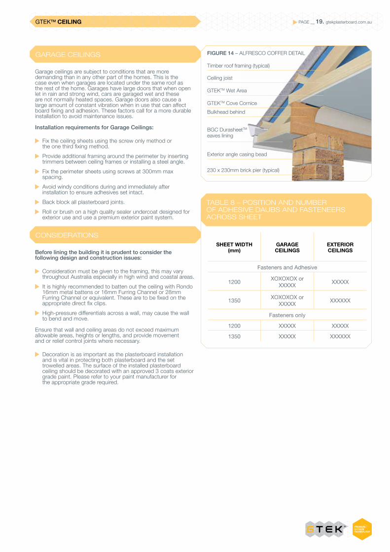
FIGURE 14 – ALFRESCO COFFER DETAIL
Timber roof framing (typical)
Ceiling joist
GTEKTM Wet Area
230 x 230mm brick pier (typical)
Bulkhead behind
Exterior angle casing bead
GTEKTM Cove Cornice
BGC DurasheetTM
eaves lining
SHEET WIDTH (mm)
GARAGE CEILINGS
EXTERIOR CEILINGS
Fasteners and Adhesive
1200 XOXOXOX or XXXXX XXXXX
1350 XOXOXOX or XXXXX XXXXXX
Fasteners only
1200 XXXXX XXXXX
1350 XXXXX XXXXXX
GTEKTM CEILING PAGE __ 20. gtekplasterboard.com.au
BACK BLOCKING
BLACK BLOCKING PROCEDURE FOR RECESSED EDGE JOINS
Back blocking is used to reinforce unsupported butt or recessed joints and must be positioned midway between supporting members, in ceilings and walls.
(a) Cut back blocks at least 200 mm wide and long enough to fit between the framing members with a gap not greater than 25mm at each end.
(b) Apply GTEKTM Back Blocking Cement over the full face of the back block. A notched spreader providing 6 mm × 6 mm beads at approximately 20mm centres at right angle to the joint would be satisfactory.
(c) Fix the plasterboard to framing members.
Back blocking must be used in open areas of ceilings (back of recessed joints) with 3 or more joints and where there is a likelihood of excessive shrinkage and movement in the structure.
(d) Place back blocks centrally along the full length of the board edge.
(e) Immediately after the back blocks are in place, fix the next sheet.
Alternatively, ceilings back blocks may be cemented into position from above the ceiling after the sheets have been fixed and before they are flush jointed.
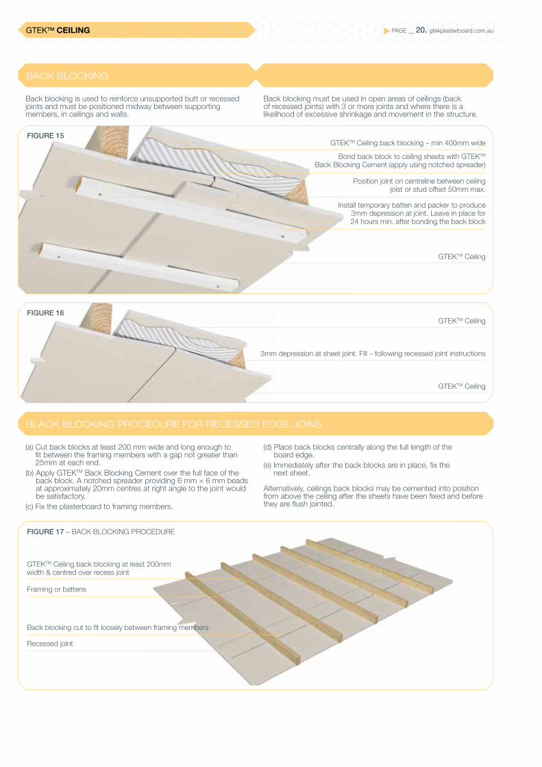
FIGURE 15
FIGURE 17 – BACK BLOCKING PROCEDURE
FIGURE 16
GTEKTM Ceiling back blocking – min 400mm wide
GTEKTM Ceiling
GTEKTM Ceiling
GTEKTM Ceiling
3mm depression at sheet joint. Fill – following recessed joint instructions
GTEKTM Ceiling back blocking at least 200mm width & centred over recess joint
Framing or battens
Recessed joint
Back blocking cut to fit loosely between framing members
Bond back block to ceiling sheets with GTEKTM Back Blocking Cement (apply using notched spreader)
Install temporary batten and packer to produce 3mm depression at joint. Leave in place for 24 hours min. after bonding the back block
Position joint on centreline between ceiling joist or stud offset 50mm max.
PAGE __ 21. gtekplasterboard.com.auGTEKTM
JOINTING APPLICATION
TAPE AND FIRST COAT
SECOND COAT
THIRD COAT
JOINTING – BUTT JOINTS
JOINTING INFORMATION FOR GTEKTM WALL, GTEKTM CEILING AND GTEKTM CURVE
Paper tape joints produce stronger and more enduring results than those that are set with fibreglass tapes.
BGC Plasterboard recommends the use of paper tapes.
Self-adhesive paper tapes should not be used.
Where fibreglass tape joints are used, they must be back blocked before the joints are set (in accordance with the instructions set out in Back Blocking, page 20).
Apply the GTEKTM Base Coat bedding cement to fully fill the recess of the joint.
Centrally bed the perforated paper tape into the bedding coat and remove any air bubbles. Apply additional cement and cover lightly with GTEKTM Base Coat.
Stop-up all fixing points and apply GTEKTM Base Coat to any damaged areas.
Allow the GTEKTM Base Coat to set and dry for a minimum of 24 hours in damp or humid conditions or 1 hour for setting type cements (or as per compound manufacturer’s recommendation).
For drying types (pre-mixed) allow a minimum of 24 hours between coats.
Lightly sand the first coat.
Check the Level of Finish prior to beginning required in the architects’ specification, before applying the second coat as detailed in Plasterboard Finish Selection (page 4).
Apply a second coat of GTEKTM Base Coat 180mm wide over the joints, making sure to feather out the edges.
Apply a second coat to all fasteners and damaged areas, feathering out by about 25mm.
Allow the second coat to set and dry for a minimum of 24 hours or 1 hour for setting type cements (or as per compound manufacturer’s recommendation).
For drying types (pre-mixed) allow a minimum of 24 hours between coats.
Lightly sand the second coat.
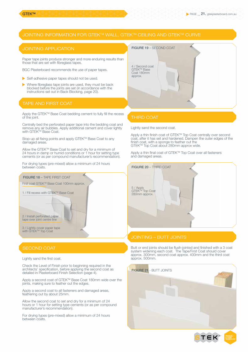
Apply a thin finish coat of GTEKTM Top Coat centrally over second coat, after it has set and hardened. Dampen the outer edges of the finish coat, with a sponge to feather out the GTEKTM Top Coat about 280mm approx wide.
Apply a thin final coat of GTEKTM Top Coat over all fasteners and damaged areas.
Butt or end joints should be flush-jointed and finished with a 3 coat system widening each coat. The Tape/First Coat should cover approx. 300mm, second coat approx. 400mm and the third coat approx. 500mm.
FIGURE 18 – TAPE FIRST COAT
FIGURE 19 – SECOND COAT
FIGURE 20 – THIRD COAT
FIGURE 21 - BUTT JOINTS
First coat GTEKTM Base Coat 100mm approx.
2 / Install perforated paper tape over joint centre line
3 / Lightly cover paper tapewith GTEKTM Top Coat
1 / Fill recess with GTEKTM Base Coat
4 / Second coat GTEKTM Base Coat 180mm approx.
5 / Apply GTEKTM Top Coat 280mm approx.
PAGE __ 22. gtekplasterboard.com.auGTEKTM
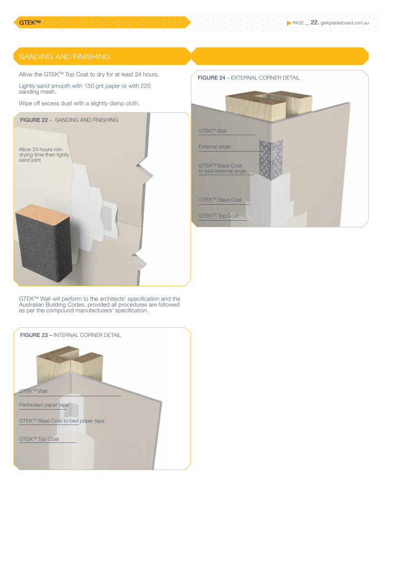
SANDING AND FINISHING
Allow the GTEKTM Top Coat to dry for at least 24 hours.
Lightly sand smooth with 150 grit paper or with 220 sanding mesh.
Wipe off excess dust with a slightly damp cloth.
GTEKTM Wall will perform to the architects’ specification and the Australian Building Codes, provided all procedures are followed as per the compound manufacturers’ specification.
FIGURE 22 – SANDING AND FINISHING
FIGURE 24 – EXTERNAL CORNER DETAIL
FIGURE 23 – INTERNAL CORNER DETAIL
Allow 24 hours min.drying time then lightlysand joint
GTEKTM Wall
External angle
GTEKTM Base Coat to bed external angle
GTEKTM Base Coat
GTEKTM Top Coat
GTEKTM Wall
Perforated paper tape
GTEKTM Base Coat to bed paper tape
GTEKTM Top Coat
PAGE __ 23. gtekplasterboard.com.auGTEKTM
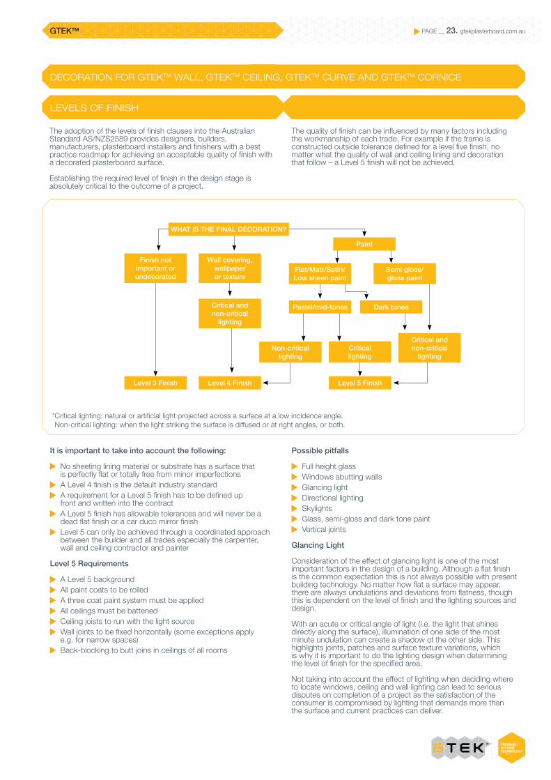
LEVELS OF FINISH
It is important to take into account the following:
No sheeting lining material or substrate has a surface that is perfectly flat or totally free from minor imperfections
A Level 4 finish is the default industry standard A requirement for a Level 5 finish has to be defined up front and written into the contract
A Level 5 finish has allowable tolerances and will never be a dead flat finish or a car duco mirror finish
Level 5 can only be achieved through a coordinated approach between the builder and all trades especially the carpenter, wall and ceiling contractor and painter
Level 5 Requirements
A Level 5 background All paint coats to be rolled A three coat paint system must be applied All ceilings must be battened Ceiling joists to run with the light source Wall joints to be fixed horizontally (some exceptions apply e.g. for narrow spaces)
Back-blocking to butt joins in ceilings of all rooms
The adoption of the levels of finish clauses into the Australian Standard AS/NZS2589 provides designers, builders, manufacturers, plasterboard installers and finishers with a best practice roadmap for achieving an acceptable quality of finish with a decorated plasterboard surface.
Establishing the required level of finish in the design stage is absolutely critical to the outcome of a project.
The quality of finish can be influenced by many factors including the workmanship of each trade. For example if the frame is constructed outside tolerance defined for a level five finish, no matter what the quality of wall and ceiling lining and decoration that follow – a Level 5 finish will not be achieved.
DECORATION FOR GTEKTM WALL, GTEKTM CEILING, GTEKTM CURVE AND GTEKTM CORNICE
Possible pitfalls
Full height glass Windows abutting walls Glancing light Directional lighting Skylights Glass, semi-gloss and dark tone paint Vertical joints
Glancing Light
Consideration of the effect of glancing light is one of the most important factors in the design of a building. Although a flat finish is the common expectation this is not always possible with present building technology. No matter how flat a surface may appear, there are always undulations and deviations from flatness, though this is dependent on the level of finish and the lighting sources and design.
With an acute or critical angle of light (i.e. the light that shines directly along the surface), illumination of one side of the most minute undulation can create a shadow of the other side. This highlights joints, patches and surface texture variations, which is why it is important to do the lighting design when determining the level of finish for the specified area.
Not taking into account the effect of lighting when deciding where to locate windows, ceiling and wall lighting can lead to serious disputes on completion of a project as the satisfaction of the consumer is compromised by lighting that demands more than the surface and current practices can deliver.
* Critical lighting: natural or artificial light projected across a surface at a low incidence angle. Non-critical lighting: when the light striking the surface is diffused or at right angles, or both.
WHAT IS THE FINAL DECORATION?
Finish not important or undecorated
Wall covering, wallpaper or texture
Critical and non-critical
lighting
Critical and non-critical
lighting
Flat/Matt/Satin/Low sheen paint
Semi gloss/ gloss paint
Paint
Dark tones
Critical lighting
Pastel/mid-tones
Level 3 Finish Level 4 Finish Level 5 Finish
Non-critical lighting
PAGE __ 24. gtekplasterboard.com.auGTEKTM
DECORATION FOR GTEKTM WALL, GTEKTM CEILING AND GTEKTM CURVE
Good choices of window placement and consideration of appropriate types of ceiling and wall lights and shades will support an even and consistent look to the surfaces.
Designers, builders and home owners should take the following into account:
Where possible ceiling and wall joints should run in the direction of the source of light e.g. at right angles to windows or large openings. Avoid butt joins where ever possible. Finished joints are subject to a variety of lighting conditions. Light intensities are constantly changing throughout the day, depending on the position of the sun, sky conditions, window, door or the location of artificial light sources and reflections from surrounding buildings, ground etc. subjecting the ceilings to diffused light from all directions.
At night, the intensity varies again. High output light sources are more severe in their effect
because they create deeper shadows. The whiter the light, the stronger the contrast, the greater the perceived imperfection.
Energy efficient fluorescent globes are non-sympathetic to plasterboard ceilings and placement is critical to control glancing light.
Light shades are some of the most effective devices for enhancing the appearance of plasterboard ceiling. By understanding the role that fittings play and the consequences of their position it is possible to minimise adverse shadowing on surfaces.
Down lights (although not the total solution) have proven excellent value for the presentation of large ceilings.
Wall mounted lights may well show up a ceiling in a kindly manner, because they are some distance below it. They will however, tend to accentuate minor imperfections in the walls.
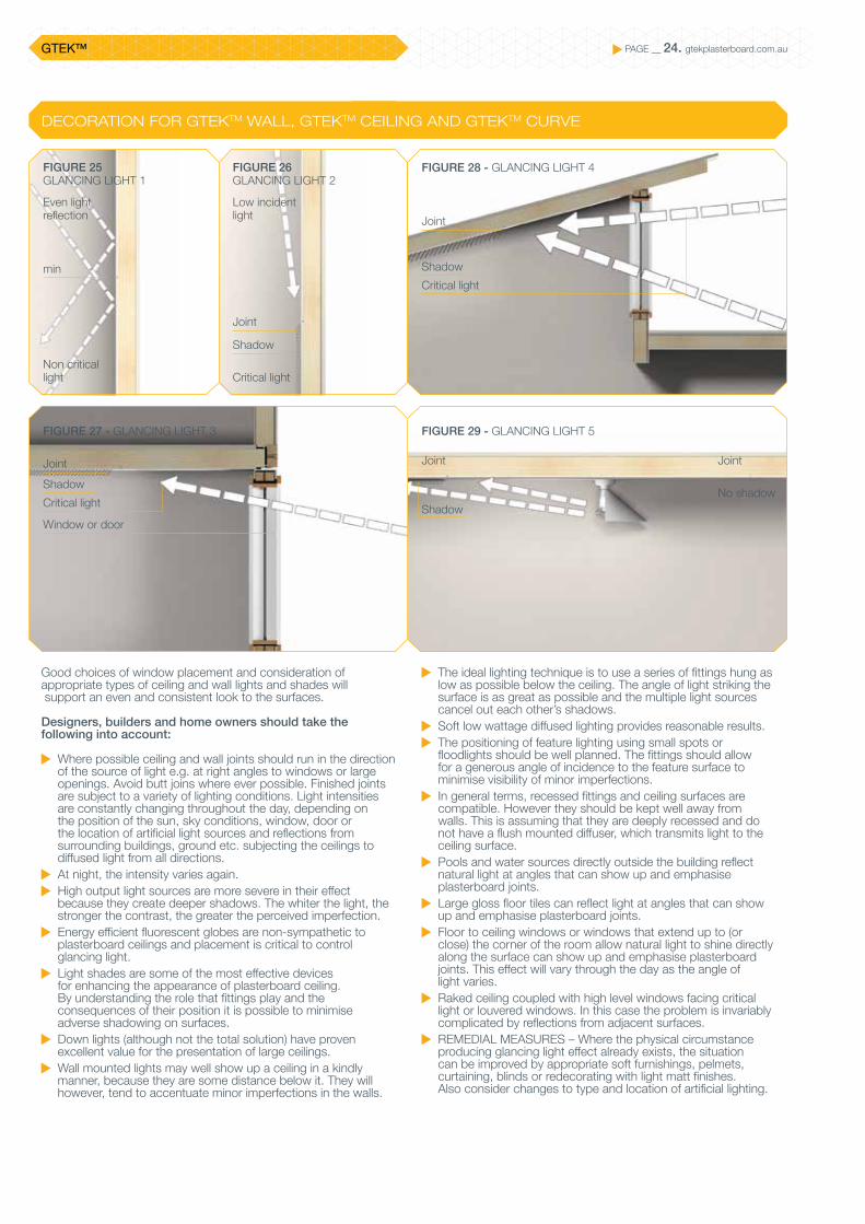
FIGURE 28 - GLANCING LIGHT 4
FIGURE 29 - GLANCING LIGHT 5
FIGURE 25GLANCING LIGHT 1
FIGURE 26GLANCING LIGHT 2
FIGURE 27 - GLANCING LIGHT 3
The ideal lighting technique is to use a series of fittings hung as low as possible below the ceiling. The angle of light striking the surface is as great as possible and the multiple light sources cancel out each other’s shadows.
Soft low wattage diffused lighting provides reasonable results. The positioning of feature lighting using small spots or
floodlights should be well planned. The fittings should allow for a generous angle of incidence to the feature surface to minimise visibility of minor imperfections.
In general terms, recessed fittings and ceiling surfaces are compatible. However they should be kept well away from walls. This is assuming that they are deeply recessed and do not have a flush mounted diffuser, which transmits light to the ceiling surface.
Pools and water sources directly outside the building reflect natural light at angles that can show up and emphasise plasterboard joints.
Large gloss floor tiles can reflect light at angles that can show up and emphasise plasterboard joints.
Floor to ceiling windows or windows that extend up to (or close) the corner of the room allow natural light to shine directly along the surface can show up and emphasise plasterboard joints. This effect will vary through the day as the angle of light varies.
Raked ceiling coupled with high level windows facing critical light or louvered windows. In this case the problem is invariably complicated by reflections from adjacent surfaces.
REMEDIAL MEASURES – Where the physical circumstance producing glancing light effect already exists, the situation can be improved by appropriate soft furnishings, pelmets, curtaining, blinds or redecorating with light matt finishes. Also consider changes to type and location of artificial lighting.
Even light reflection
Low incident light
Joint
Joint
Joint
Shadow
Shadow
Joint
No shadow
Joint
Critical light
Window or door
ShadowNon critical light Critical light
min ShadowCritical light

PAGE __ 25. gtekplasterboard.com.auGTEKTM CORNICE
GTEK™ Cove and decorative cornices are available in three profile sizes suited to all applications.What's good about GTEK™ Cove and Decorative Cornices
Designed to improve appearance of junctions at walls and ceilings
Easy-on-the-eye designs Quick and simple to install Three cove cornice profile sizes: – 55mm – 70mm – 90mm
Also GTEKTM Esperance 75mm profile
Complementing our GTEK™ plasterboard sheets, BGC offers a range of GTEK™ cove and decorative cornices, adding exciting finishing touches to interior wall and ceiling joints in new builds and renovations.
GTEKTM CORNICE
No shadow
Joint
BGC-2014GECA 04-2011 v2
Panel Boards
GTEKTM CORNICE PAGE __ 26. gtekplasterboard.com.au
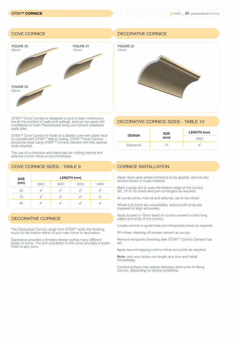
COVE CORNICE
COVE CORNICE SIZES - TABLE 9
DECORATIVE CORNICE SIZES - TABLE 10
DECORATIVE CORNICE
CORNICE INSTALLATION
DECORATIVE CORNICE
GTEKTM Cove Cornice is designed to give a clean continuous line at the junction of walls and ceilings, and can be used with confidence on both Plasterboard lining and cement plastered walls alike.
GTEKTM Cove Cornice is made of a plaster core with paper face to complement GTEKTM Wall & Ceiling. GTEKTM Cove Cornice should be fixed using GTEKTM Cornice Cement with few special tools required.
The use of a mitre box and hand saw for cutting internal and external corner mitres is recommended.
The Decorative Cornice range from GTEKTM adds the finishing touch to the interior décor of your new home or renovation.
Esperance provides a timeless design suiting many different styles of home. The soft undulation of the curve provides a stylish finish to any room.
Clean down area where cornice is to be applied, remove any excess render or loose material.
Mark a guide line to suite the bottom edge of the cornice (90, 75 or 55 down) and pre-cut lengths as required.
All corner joints, internal and external, are to be mitred.
Where butt joints are unavoidable, ensure both ends are prepared to align accurately.
Apply (butter) a 10mm bead of cornice cement to both long edges and ends of the cornice.
Locate cornice to guide lines and temporarily block as required.
Fill mitres, cleaning off excess cement as you go.
Remove temporary blocking after GTEKTM Cornice Cement has set.
Apply second topping coat to mitres and joints as required.
Note: only ever butter one length at a time and install immediately.
Contact surface may require damping down prior to fixing cornice, depending on drying conditions.
FIGURE 3375mm
DESIGN SIZE(mm)
LENGTH (mm)
4800
Esperance 75 ü
SIZE (mm)
LENGTH (mm)
3000 3600 4200 4800
55 ü ü ü ü
75 ü ü ü ü
90 ü ü ü ü
FIGURE 3175mm
FIGURE 3255mm
FIGURE 3095mm

GTEKTM WALL & CEILING SOLUTIONS PAGE __ 27. gtekplasterboard.com.au
NOTES
GTEKTM WALL & CEILING SOLUTIONS PAGE __ 28. gtekplasterboard.com.au
NOTES
GTEKTM WALL & CEILING SOLUTIONS PAGE __ 29. gtekplasterboard.com.au
NOTES

GOOD ENVIRONMENTAL CHOICE AUSTRALIA GECA PAGE __ 30. gtekplasterboard.com.au
At BGC we care about the environment and now have a range of GECA Certified Plasterboard Products available. As part of our commitment to sustainability we are offering our Environmentally Certified GTEKTM range at no extra cost to you. So now you save money whilst together we save the environment.
BGC-2014GECA 04-2011 v2
Panel Boards
GOOD ENVIRONMENTAL CHOICE AUSTRALIA GECA PAGE __ 31. gtekplasterboard.com.au
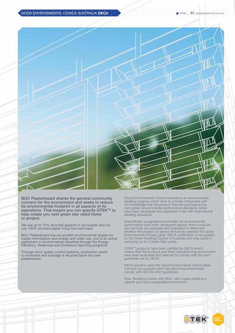
BGC Plasterboard shares the general community concern for the environment and seeks to reduce its environmental footprint in all aspects of its operations. That means you can specify GTEKTM to help create you next green star rated home or project.We use up to 15% recycled gypsum in our boards and we use 100% recycled paper lining front and back.
BGC Plasterboard has set prudent environmental targets for waste minimisation and energy and water use, and is an active participant in environmental reporting through the Energy Efficiency, Waterwise and Emissions reporting programs.
Through strict quality control systems, production waste is minimised and wastage is recycled back into new plasterboard.
Good Environmental Choice Australia is an environmental labelling program which aims to provide consumers with the knowledge that the product they are purchasing has met certain environmental performance standards which have been developed and assessed in line with International labelling standards.
Scientifically recognised benchmarks for environmental performance have been developed against which products and services are assessed and evaluated to determine whether the product or service should be awarded the Good Environmental Choice Label. GECA certification is recognised by the Green Building Council of Australia and may assist in achieving up to 3 Green Star points.
GTEKTM products have been certified by GECA which means that the products and their manufacturing environment have been evaluated and deemed to comply with the strict guidelines set by GECA
We’re proud to wear the Good Environmental Choice label, it shows our products and manufacturing environment comply with GECA’s strict guidelines.
Now ‘Building it better with BGC’ also means building a cleaner and more sustainable environment.

Design by The SHAPE Group www.theshapegroup.com.au
CONTACT
TO CONTACT YOUR NEAREST BGC STOCKIST, PLEASE CALL:
ADELAIDETELEPHONE 08 8250 4962BRISBANETELEPHONE 07 3271 1711MELBOURNETELEPHONE 03 9392 9444PERTHTELEPHONE 08 9374 2900SYDNEYTELEPHONE02 9771 9660
NEW ZEALANDTELEPHONE0011 64 9273 1457
TECHNICAL HELP LINE1300 652 242
WARRANTYGTEKTM PRODUCT RANGE
We warrant that our products are free from defects caused by faulty manufacture or materials for a period of 15 years from the date of purchase. If you acquire any defective products, we will repair or replace them, supply equivalent replacement products or refund the purchase price within 30 days of receiving a valid claim subject to product inspection and confirmation of the existence of a defect by BGC. We will bear the cost of any such repair, replacement or refund.
This warranty is given by:
BGC PLASTERBOARD PTY LTDGround Floor, 290 Bushmead Rd, Hazelmere, WA 6055 Phone: (08) 9374 2900 Fax: (08) 9374 2901
To claim under this warranty, you must provide proof of purchase as a consumer and make a written claim (including any costs of claiming) to us at the address specified above within 30 days after the defect was reasonably apparent, or if the defect was reasonably apparent prior to installation, the claim must be made prior to installation. You may not claim under this warranty for loss or damage caused by:
faulty or incorrect installation by non-BGC installers (BGC’s installation procedures are at gtekplasterboard.com.au);
failure to comply with the Building Code of Australia or any applicable legislation, regulations approvals and standards;
products not made or supplied by BGC; abnormal use of the product; or normal wear and tear.
The benefits available under this warranty are in addition to other rights and remedies of the consumer under the law. Our goods come with guarantees that cannot be excluded under the Australian Consumer Law. You are entitled to a replacement or refund for a major failure and for compensation for any other reasonably foreseeable loss or damage. You are also entitled to have the goods repaired or replaced if the goods fail to be of acceptable quality and the failure does not amount to a major failure.
GTEK™ Wall is an interior wall lining system where cost effectiveness and economy of effort is crucial.
GTEK™ Curve flexible plasterboard enables the creative execution of curves on interior walls and ceilings.
GTEK™ Ceiling is a 10mm plasterboard sheet designed specifically for ceiling use where joists are at 600mm.
GTEK™ Fire is used in fire-rated systems, consisting of single or multiple layers of board.
GTEK™ Fire & Wet Area is designed for use in wet areas governed by fire resistance limitations (FRLs).
GTEK™ Wet Area is water-resistant plasterboard for walls in such wet areas as bathrooms, laundries, toilets and cleaning rooms.
GTEK™ Sound is high-density plasterboard specifically designed to reduce unwanted noise detectable through walls and ceilings.
GTEK™ Impact is ideal for high-traffic areas where walls are subjected to regular stress.
GTEK™ Total Plus offers market- leading fire, water, sound and impact resistance, together with GECA certification in recognition of high percentages of recycled materials.
GTEK™ Cornice adds exciting finishing touches to interior wall and ceiling joints in new builds and renovations.
BGC-2014GECA 04-2011 v2
Panel Boards