Embed Size (px)
Citation preview
A GYRATORY COMPACTOR FOR MOLDING LARGE DIAMETER TRIAXIAL SPECIMENS OF GRANULAR MATERIALS
Lionel J. Milberger Research Assistant
and
Wayne A. Dunlap Assistant Research Engineer
Research Report Number 99-2 Stress Distribution in Granular Masses
Research Study Number_ 2-:8-65-99
Sponsored by The Texas Highway Department
in Cooperation with the U. S. Department of Commerce 1 Bureau of Public Roads
October, 1966
TEXAS TRANSPORTATION INSTITUTE Texas A&M University
College Station, Texas
I

TABLE OF CONTENTS
Page
LIST OF FIGURES -iii
ACKNOWLEDGEMENTS iV
tl ... : ·_ SYNOPSIS . • . . . . . . . . . . . . ) . . 1
2. INTRODUCTION 2
3. REVIEW OF LABORATORY COMPACTION PROCESSES 4
4. DESCRIPTION OF THE GYRATORY COMPACTOR .. 10
5. COMPACTOR OPERATION ...........• 18
6. DESIGN PROBLEMS AND 'RECOMMENDATIONS :-FOR FUTURE MODELS . . . . . 26
7. CONCLUSIONS 27
REFERENCES . . . • . • • • • 2 9
ii
LIST OF FIGURES
Figures
1 . Schematic Diagram Illustrating Principle of Operation
2 a Front View of Gyratory Compactor
3. Side View of Gyratory Compactor
4. Split Compaction Mold Initially Used with the Compactor
5. Hardened Steel Compaction Mold .. e ••••
6. Split Surface Hardened Steel Compaction Mold
7. Split Ce'ramic-Lined Compaction Mold ..
8o Compaction Mold Ready for Filling .
9" Assembly View of Compactor . G •• • • ~. • 8 •
10. Strain Gauge Installation on Drive Shaft of Compactor
11. Mosely Recorder and Bridge Balance Unit . . . ...
12. Recording Obtained From Strain Gauge Installation ..
13. Cross Section of Specimen Compacted by Texas Highway Department Impact Method . . . . . . . . . . . . . . . .
Page
11
12
13
. . 16
. 16
. 17
17
19
20
• 23
• 23
24
28
14 o Cross Section of Specimen Compacted in Gyratory Compactor . . . . 2 8
iii
ACKNOWLEDGEMENTS
The basic design of the gyratory compactor was conceived primarily by Messrs. Lionel J .· Milberger and Tommy L. Snow, Research Assistants, Texas Transportation Institute~ Mr. Carl Poling, Hydraquip, Inc., Houston, Texas, contributed significantly to the design of the hydraulic system.
Special thanks are due Messrs. Tom Gillis and Wayne Best, Ceramic Coatings, Inc. , Houston, Texas, for their technical and financial assistance in the design, development, and construction of the hardened steel and ceramic lined compaction molds and associated mold chuck.
Other staff members and personnel of the Texas Transportation Institute who contributed to the design of the compactor or the preparation of information contained in this report include Messrs. F. H. Scrivner, Chester Michalak, M. T. H. Al-Layla, L. E. Stark, and Richard Van Pelt.
The opinions, findings, and conclusions expressed in this publication are those of the authors and not necessarily those of the Burea ti of· Public Roads.
iv

A GYRATORY COMPACTOR FOR MOLDING LARGE DIAMETER TRIAXIAL SPECIMENS OF GRANULAR MATERIALS
1. SYNOPSIS
A mechanical gyratory compactor is described which was developed for fabricating 6-inch diameter by 12-inch high triaxial test specimens of granular materials. The apparatus was constructed after a review of existing laboratory compaction techniques and equipment which indicated that s·uitable, economical methods for this purpose were not available. A detailed description of the compactor is presented as well as a detailed discussion of the compactor operation. Fabrication drawings of the compactor are not included, . but they . are available upon requ.est.
In principle, the compactor is a. mechanical modification of the manu~l gyratory compactor developed in the early 1940's by the Texas Highway Department for molding asphaltic concrete specimens. The excessive forces required to gyrate and then level large specimens of granular materials necessitated a unique gyratory model~ but the components used in the compactor are, for the most part 1 stock items which are readily available.
Operation is semiautomatic and requires no manual effort on the part of the operator. An important feature of the compactor is the wide latitude in the applied compactive effort; it can be varied by changing the magnitude of the vertical pressure, the angle of gyration I the speed of gyration, and the number of gyrations. Electronic equipment for obtaining a measure of the compactive effort is. included on the compactor.
It is necessary to develop special compaction molds -- one being of ceramic-lined steel which represents a new and potentially valuable concept in compaction molds.
A subsequent publication will study the ability of the compactor to perform its design objectives. At this time, however, _cross- sections of compacted specimens show no particle segregation, and densities of replicate specimens are virtually identicaL
2. INTRODUCTION
,Increases in traffic volumes, and in the weights and tire pressures of commercial vehicles, have placed heavy demands on the load carrying capacities of modern highways. In particular, the near surface layers of flexi}:)le pavements (the granular base course materials) have been affected; shear failures and settlement caused by traffic compaction are not uncommon~
The factors influencing the performarice.of granular base course: materials are usually surmised from observation of field test sections or model.pavements. Laboratory investigations where the variables could be more closely controlled than in the field have been severely restricted owing to the difficulty of fabricating representative specimens of these materials ih the laboratory.
. ' ' .
Purpose of Research
One of the primary objectives of this ·project was to deve;lop a suitable method of fabricating specimens and determining laboratory compaction. characteristics of granular materials. The need for this study became apparent from the results of two other projects conducted by the Texas Transportation Institute.
Phase Three of Project 2-8-62-32, 11APPlication of the AASHO· Road T~st Results to Texas Conditions, 11 was a. field sampling and testing study. It was the intent of this study to compact the materials in the laboratory at. their in- situ moisture contents, densities, and gradations and then determine the strengths of the remolded specimens. But ;in many cases the Texas Highway Department District Laboratories found it impossible to reproduce these conditions on granular materials using the standard Texas Highway Department Laboratory compaction method.
A portion of Project 2- 8-62-2'7, 11 Distribution of Stresses -in Layered Systems Composed of Granular Materials," was devoted to determining the strength and deformation characteristics of granular materials subjected to repetitive triaxial loading in the laboratory. One of the greatest difficulties encountered in this research was the fabrication 9f suitable specimens of the materials using the Texas Highway Department compaction method modified to make 12-inch high triaxial specimens. In spite of this, the general repetitive triaxial testing program was successful enough to warrant additional testing, not only on specimens compacted at optimum moisture content, but on ones compacted at the in-situ conditions. But first it was necessary to be able to fabricate 6-inch diameter by 12-inch high triaxial specimens which would meet the following requirements:
A. Be reproducible from specimen to specimen.
-2-
B. Be uniform throughout the specimen length insofar as density, moisture content and gradation were concerned.
C. Be capable of being molded at in-situ molsture contents, densities I and gradations.
Before an attempt' was made to develop a new item of equipment to accomplish the above objectives I a review was made of available compaction methods and equipment to see if any of these were suitable or could be modified to accomplish the objectives.
Scope of Report
This publication is restricted to the design, construction, and operation of a compactor developed to accomplish the above objectives. Results of an investigation of the ability of the gyratory compactor to perform its design objectives will be the subject of a subsequent publication.
-3-
3. REVIEW OF LABORATORY COMPACTION PROCESSES
General
Below is presented a brief summary of laboratory compaction methods which are used or have been used to determine compaction characteristics of soils and to prepare disturbed specimens for subsequent testing. No attempt has been made to present a detailed discussion of these procedures G For this, the reader is referred to the excellent works by Johnson and Sallberg ( 5) 1 Johnson and Guinee ( 4), Foster ( 3), and reports of the Waterways Experiment Station ( 9). Instead I this review is confined to a short description of the more common methods~ their shortcomings and their advantages I particularly as related to the purpose and scope of this report 0
Impaction Compaction
·The first scientific approach to determine laboratory compaction characteristics of soils is generally credited to R. R. Proctor ( 1933). His procedure was slightly revised and adopted as a standard by the American Association of State Highway Officials in 1939 ( AASHO Designation: T-99 ); later it was modified to allow higher compactive efforts ( AASHO Designation: T-180). This method is generally termed impact compaction, i.e. I the soil is compacted in a rigid mold by dropping a hammer of known weight on it from a specified height.
Numerous modifications of impact compaction procedures have been developed to suit specific requirements. For example, the Texas Highway Department uses a procedure in which four 2-inch thick layers of soil are comp(lcted in a 6-inch diameter mold. An automatic compactor with a 10- pound hammer having an 18 -inch drop is used to compact the 8-inch-high specimen. As opposed to the standard and modified AASHO methods -- which now allow 3/ 4-lnch maximum size aggregate -the Texas Highway Department method allows 2-inch maximum size aggregate, thereby eliminating; in most cases the need for correcting laboratory results to compensate for larger aggregate which might be used in the field.
In the authors 1 opinion all impact methods have certain inherent disadvantages, particularly for granular materials. Some of these are:
A. Aggregate distribution and orientation are unlike those which occur in field compaction e
B. Stress-strain curves are not similar to stress-strain curves obtained from field compaction specimens. (This is undoubtedly influenced to a great extent by A. above. )
-4-
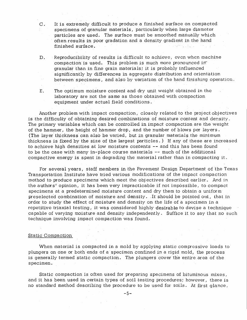
C ~ It is extremely difficult to produce a finished surface on compacted specimens ofgrariular materials, particularly when large diameter particles are used. The surface must be smoothed mari.ually which often.results in ppor gradation and a density gradient in the hand finished surface.
D. Reproducibility of results is difficult to achieve, even when machine compaction is used. This problem is much more pronounced ir1 granular than in fine grain materials; it is probably influenced significantly by differenoes in aggregate distribution and orientation between specimens I and also by variation of the hand finishing operation,
E. The optimum moisture content and dry uni~ weight obtained in the labor a tory are not the sa me as those obtained with compaction equipment under actual field conditions.
Another problem with impact compaction~ closely related to the project: objectives is the difficulty of obtaining desired c,ombinations of moisture content and density. The primary variables which can be controlled in impact compaction are the weight of the hammer, the height of hammer drop, and the number of blows per layers. (The layer. thickness can also be varied, but in granular materials the minimum thickness is fixed by the size of the largest particles. ) If any of these are increased to achieve high densities at low moisture contents -- and this has been found to be the case with many in-place course rna terials -- much of the additional compactive energy is spent in degrading the material rather than in compacting it,,
For several years, staff members in the Pavement Design Department of the Texas Transportation Institute have tried various modifications of the impact compaction method to produce specimens which meet the objectives described earlier. And tn the authors' opinion, it has been very impracticable if not impossible, to compact specimens at a predetermined moisture content and dry them: to obtain a uniform preselected combination of moisture and density .. It should be pointed out, that in order to study the effect of moisture and density on the life of a specimen in a repetitive triaxial testing, it- was considered highly ·desirable to devise a technique capable of varying moisture and density independently. Suffice it to say that no such technique involving impact compaction was found..
Static Compaction
When material is compacted in a mold by applying static compressive loads to plungers on one or both ends of a specimen confined in a rigid mold 1 the process is generally termed static compaction. The plungers cover the entire area of the specimen.
Static compaction is often used for preparing specimens of bituminous mixes u
and it has been used in certain types of soil testing procedures; however I there is no standard method describing the procedure to be used for soils. At first glance,
-5-
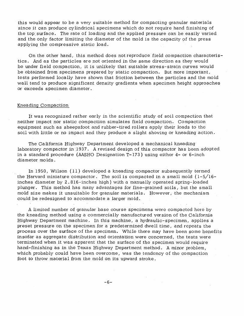
this would appear to be a very suitable method for compacting granular materials since it can produce cylindrical specimens which do not require hand finishing of the toP .. surface. The rate of loading and the applied pres sure can be easily varied and the only factor limiting the diameter of the mold is the capacity 9£ the press applying the compressive static load.
On the other hand, this method does not reproduce field compaction characteristics. And as the particles are not oriented in the same direction as they would be under field compaction, it is unlikely that suitable stress-strain curves would be obtained from specimens prepared by static compaction. But more im:portant, tests performed locally have shown that friction between the particles and the mold wall tend to produce significant density gradients when specimen height approaches or exceeds specimen diameter.
Kneading Compaction
It was recognized rather early in the scientific study of soil compaction that neither impact nor static compaction simulates field compaction. Compaction equipment such as sheepsfoot and rubber-tired rollers apply their loaos to the soil with little or no impact and they produce a slight shoving or kneading action.
The California Highway Department developed a mechanical kneading laboratory compactor in :l937. A revised design of this compactor has been apopted in a standard procedure (AASHO Designation T-173) using either 4- or 6-inch diameter molds.
In 1950, Wilson ( 11) developed a kneading compactor subsequently termed the Harvard miniature compactor. The soil is compacted in a small mold ( 1-5/16-inches diameter by 2. 816-inches high) with a manually operated spring-loade,<if plunger. This method has many advantages for fine-grained soils, but the small mold size makes it unsuitable for granular materials. However, the mechanism could be redesigned to accommodate a larger mold.
A limited number of granular base course specimens were compacted here by the kneading method using a commercially manufactured version of the California Highway Department machine. In this machine, a hydraulic-specimen, applies a preset pressure on the specimen for a predetermined dwell time, and repeats the process over the surface of the specimen. While there may have been some benefits insofar as aggregate distribution and orientation were concerned, the tests were terminated when it was apparent that the surface of the specimen would require hand-finishing as in the Texas Highway Department method. A minor problem, which probably could have been overcome! was the tendency of the compaction foot to throw material from the mold on its upward stroke.
-6-
Vibratory Compaction
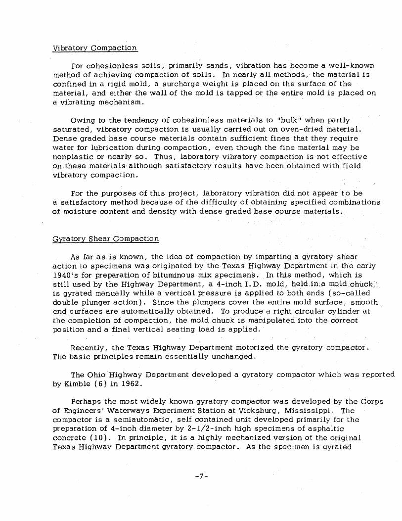
For cohesionless soils, primarily sands I vibration has become a well-known method of achieving compaction of soils~ In nearly all methods I the material is confined in a rigid mold 1 a surcharge weight is placed on the surface of the material, and either the wall of the mold is tapped or the entire mold is placed on a vibrating mechanism.
Owing to the tendency of cohesionless materials to 11 bulk n when partly saturated, vibratory compaction is usually carried out on oven-dried material. Dense graded base course materials contain sufficient fines that they require water for lubrication during compaction 1 even though the fine mat"erial may be nonplastic or nearly so. Thus, laboratory vibratory compaction is not effective on these materials although satisfactory results have heen obtained with field vibratory compaction.
For the purposes of this project, laboratory vibration did not appear to be a satisfactory method because of the difficulty of obtaining specified combinations of moisture content and density with dense graded base course materials.
Gyratory Shear Compaction
As far as is known I the idea of compaction by imparting a gyratory shear action to specimens was originated by the Texas Highway Department in the early 1940's for preparation of bituminous mix specimens. In this method, which is still used by the Highw.ay Department, a 4-inch I. D. mold, heldjn:a moJd.:chuck~~ .. is gyrated manually while a vertical pressure is applied to both ends {so-called double plunger action). Since the plungers cover the enUre mold surface I smooth end surfaces are automatically obtainedo To produce a right circular cylinder at the completion of compaction I the mold chuck is manipulated into the correct position and a final vertical seating load is appliedo
Recently 1 the Texas Highway Department motorized the ~yratory compactor o
The basic principles remain essentially unchanged o
The Ohio ·Highway Department developed a gyratory compactor which was r~ported by Kimble ( 6) in 1962 0
Perhaps the most widely known gyrato,ry compactor was developed by the Corps of Engineersg Waterways Experiment Station at Vicksburg I Mississippi. The compactor is a semiautomatic, self contained unit developed primarily for the preparation of 4-inch diameter by 2-1/2-inch high specimens of asphaltic concrete ( 10) . In principle I it is a highly mechanized version of the original Texas Highway Department gyratory compactor. As the specimen is gyrated
-7-
through a preset angle, the compactor produces a graph,. coined a 11 gyrograph. 11
The width of the gyrograph is a function of the gyratory angle through which the specimen is g:yrated. Changes in the width of the gyrograph during compaction of a specimen are produced by a change in the resistance of the specimen to gyration.
The above gyratory compactor has been modified to produce 6-inch diameter specimens and it can be further modified to produce 6-inch by 12-inch cylindrical specimens ( 7). It is now produced commercially by Engineering Developments Company, Vicksburg, Mississippi.
Recently, the Waterways Experiment Station and others have used the compactor to prepare specimens of granular base course materials. Although published results are concerned with specimens whose height is less than their diameter, the results are encouraging.
Parsons((S)·used the compactor to prepare 4-in.c_h. diameter specimens of a crushed limestone base course. He was able to produce a wide range of density and moisture content combinations by changing the compactor variables. He, and others, have detected a widening of the gyrograph band at certain combinations of moisture content and density which could be attributed to an increase in the pore pressures with increased compactive effort.
Al-Layla ( 1) compacted specimens of a crushed caliche limestone which was also used for repetitive triaxial tests conducted under Project 2-8-62-27. He was able to obtain densities nine pcf higher than those obtained with the same material compacted by the standard Texas Highway Department impact compaction method. This was achieved without significant degradation of the material, where~s, if the impact compactive effort was progressively increased, a maximum density increase of only three pcf could be obtained ( 2). It is interesting· to note that under repetitive triaxial loading, the ~ensity of the · material -- compacted initially by the standard Texas Highway, Del(Cirtmen.t method.-;:increased abqut 7 pcf or roughly the ~arne increase Al-Layla .was able to ach~eve with gyratory compaction. · ·
Both Parsons and Al-Layla observed that considerable water extruded from wet specimens prepared at high compactive efforts. This created some doubt as to whether the initial or final moisture content should be used for plotting moisture content versus density results. Otherwise, the gyratory compactor was adjusted quite satisfactory for preparing specimens of granular materials.
Summary
Impact, static, kneading, vibratory and gyratory compaction methods were examined to determine their applicability for fabricating large diameter specimens of
-8-
granular materials. These five compaction methods encompass the general range of methods which are available, but variations and combinations of each technique have been developed which, in some cases I are extensive enough to virtually disguise the basic method.
Each compaction method undoubtedly has certain advantages I but only the · gyratory shear method appears to have the prime requisites to satisfy the desired objectives outlined earlier. Impact and kneading methods require hand finishing to smooth the surface of the compacted specimen. With static compaction, the final surface is smooth but a high density gradient occurs through the length of long cylindrical specimens and there are few variables which can be changed to achieve the desired range of density and moisture content combinations. Vibratory methods certainly have their place with cohesionless materials 1 but dense graded base course materials contain sufficient fines so that they need moisture to achieve lubrication. Vibratory methods do not appear suitable ·for these rna terials.
While the gyratory method appears most suitable, there is only one commercially available gyratory compactor, and it was developed primarily to compact a specimen whose height did not exceed its diameter. Thus, the decision was made to develop a new gyratory compactor designed specifically to fabricate long cylindrical specimens of high strength granular materials. The remainder of this report is concerned with this compactor, its description and operation.
-9-

4. DESCRIPTION OF THE GYRATORY COMPACTOR
General
Once the decision was made to· use the g_yrq.tory principle for fabricating specimens, it was necessary to· deve.lop :a gyratory 1nechanism sturdy enough to withstand the large forces necessary for granular materials, but with.the capability of leveling up the specimen at the end of gyration to produce a right circular cylinder. While this might justly be regard~d ~?S t:he primary design problem, tqe development of a satisfactory compaction mold·, and a mean~ of measuring or indicating the compactive effort, also·n~qU!red careful coris.ideration o In addition, since the compactor was to be primarily an item for research, every effort was made to insure complete flexibility of operation and close control of the machine variables.
The gyratory mechanism eventually developed bears some similarity in principle to the apparatus described by Kimble, however, the method by which it operates is different. The principle of operation for the compactor is descri.bed below 8
Principle of Operation
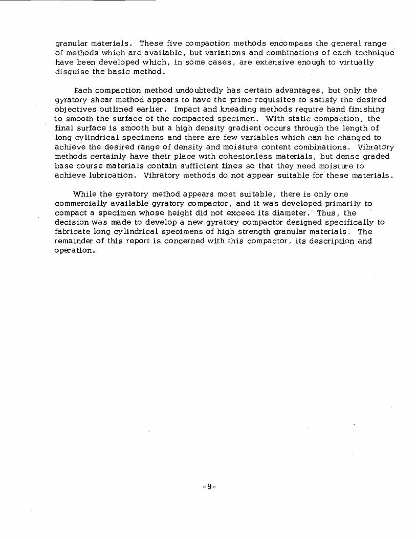
The mold is gyrated about a fixed point at the bottom of the mold so that the center line of the mold circumscribes a cone whose vertex concides with the center of the mold base~ The actual operation can be explained with respect to the schematic diagram shown in Figure 1.
Mold A, containing the soil, is clamped in the split mold chuck, B. The gyratory arm C, is affixed to the mold chuck and connected to the upper hydraulic ram by a spherical ball bearing, E. The hydraulic ram, D, forces the gyratory arm off center, tilting the mold axis to the desired gyratory angle, 9. When the rotating plate unit turns, a gyratory motion about the fixed base plate F is imparted to the entire mold chuck assembly.
Vertical pressure on the specimen is applied by the ram G. By keeping the bottom of the mold suspended off the fixed base plate assembly, F, a double plunger effect is produced. Note that the bearing plate H is free to move .in a horizontal plane; it slides on a virtually frictionless assembly, I~ attached to ram G. Pressure to the two rams is supplied by a hydraulic pump-power unit. Each ram has a separate pressure regulator 1 control valve and gauge. The rotating plate unit is powered by a variable speed drive.
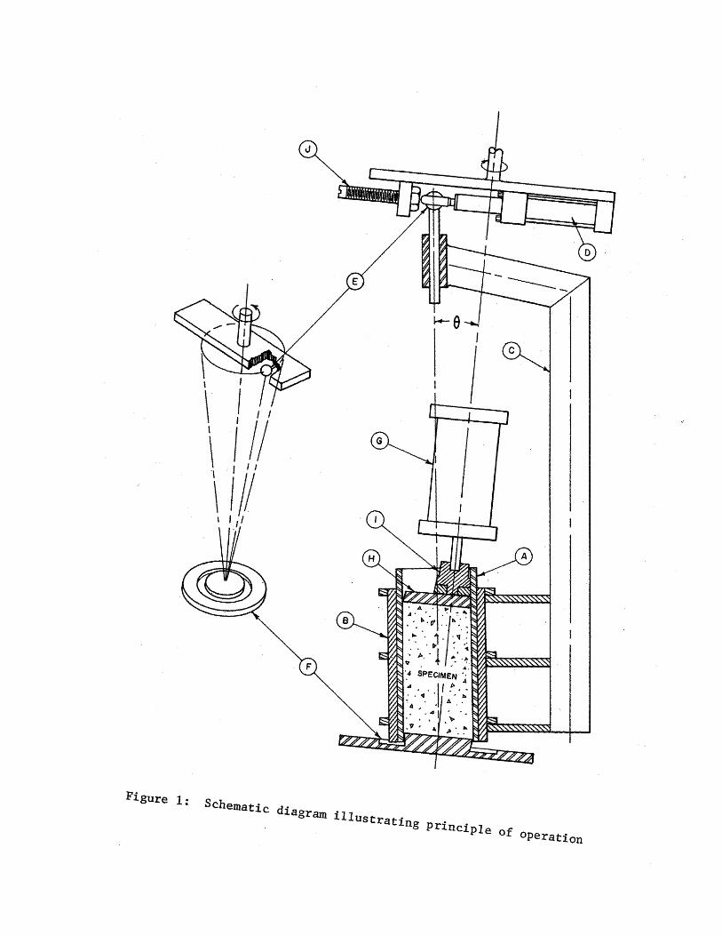
Figure 2 and 3 are front and side views of the compactor.
-10-
I
\ I I l
I I II \ I I
\ I II l I I
Figure l: Schematic diagram illustrating principle of operation
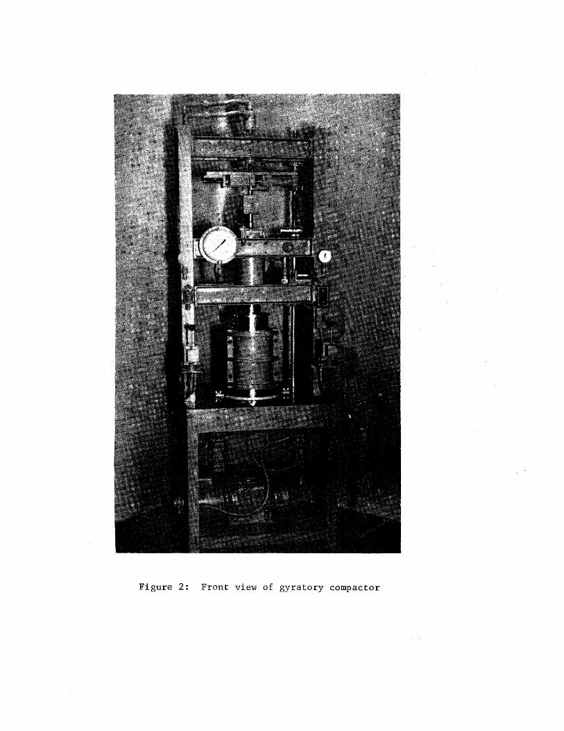
Figure 2: Front view of gyratory compactor
Figure 3: Side view of gyratory compactor
The unique feature of this compactor is that several factors influencing the degree of compaction are capable of being varied. These are:
I
A. The vertical pressure/ p/ which can be regulated from zero to 500 psi.
B. The gyratory angle I 9, which can be varied up to four degrees and then returned to zero to level up the specimep.
C. The speed of gyration/ w, which can be adjusted up to a maximum of 2 5 gyrations per minute.
D. The number of revolutions I N I which is controlled by a preset predetermined counter-switch.
In addition, there is a fifth variable I related to another operation the compactor can perform I which will be discussed later.
The key items of equipment which enable the compactor to perform satisfactorily are a rotatory union, a spherical ball bearing, and a variable speed drive. The rotatory union provides a means whereby two pressurized hydraulic lines can be transmitted through a rotating shaft to a double acting ram. Such an arrangement provides a means whereby the gyratory angle can be maintained or changed during gyration.
The spherical ball bearing, permits both rotational and angular movement so the· gyratory arm can effortlessly assume the correct position.
The variable speed drive has a calibrated dial to accurately control the speed of gyration.
Compaction Mold
The co:rifiguratio.n· of the mold and the material .from which it is made can significantly influence the compactor's ability to produce sa tis factory specimens. The large peripheral area of 6-inch diameter by 12-inch high specimens necessitates large forces to extrude the specimens from the compaction mold .. These forces can, in turn, create significant disturbance of the specimen. In addition, excessive friction between the mold walls and the specimen exterior can not only increase the extrusion force I but it can also cause density gradients by preventing the central portion of the specimen from receiving the full applied vertical force.
Obviously, the solution to these problems is a mold of smooth, hard interior surface which is also s;plit longitudinally so that the specimen can be removed easily 0
Different molds have been tried on the compac~or to secure the optimum arrangement.
-14-
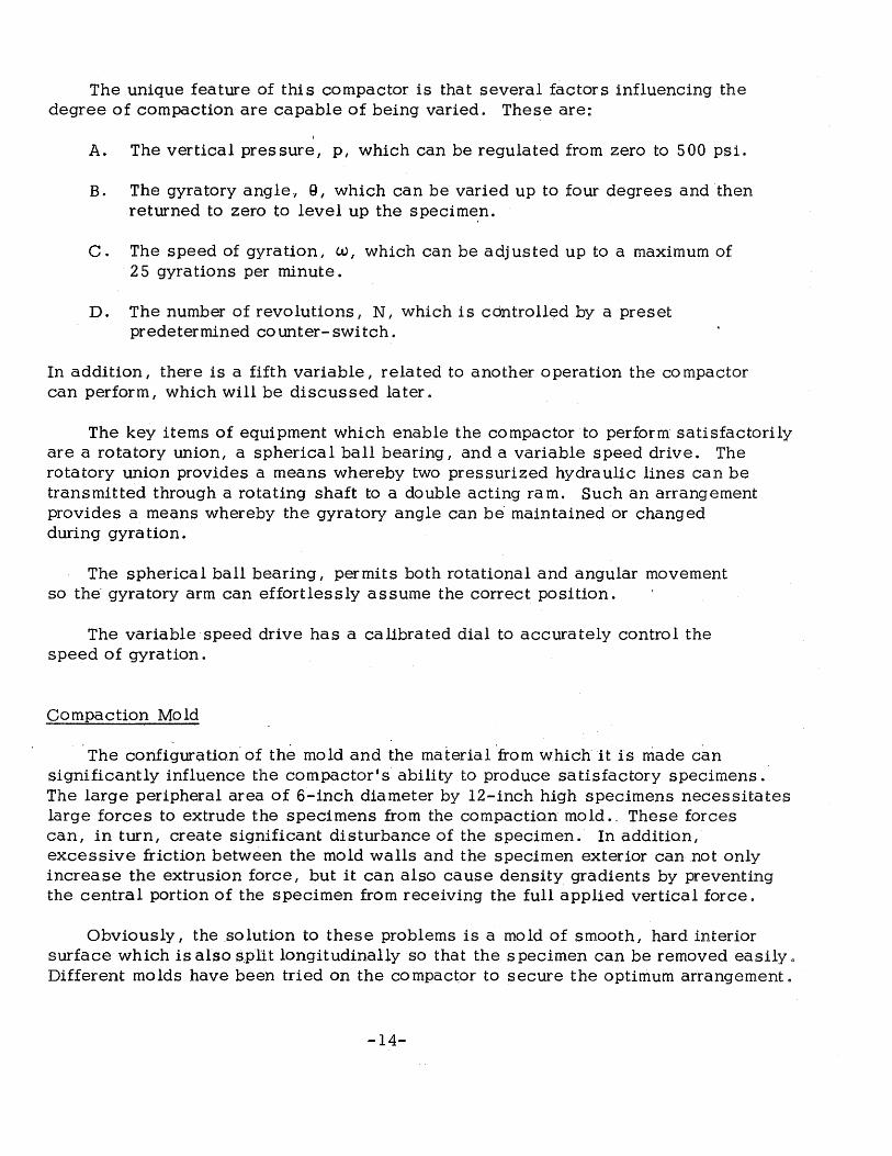
The initial mold was constructed from the same high tensile strength steel used for the present 6-inch diameter Texas Highway Department compaction molds (see Figure 4). The mold was split longitudinally (on one side only) to facilitate removal of the compacted specimen. However, the high tensile strength steel was not sufficiently hard and the interior of the mold quickly developed striations and excessive roughness.
Subsequently 1 a mold of hardened steel with a highly polished interior was obtained (see Figure 5) e The hardness of this mold was 62 on the Rockwell C scale which is roughly equivalent to the hardenss of quartz ( 7 o 5 on the Moh hardness scale) 1 the hardest natural materia 1 anticipated in granular soils. This particular mold could not be split due to its hardness; as a result high extrusion forces were required. Nevertheless 1 the mold interior showed no visible markings after many specimens were compacted in it I and it appeared promising enough to have a special split hardened mold manufactured for further trials.
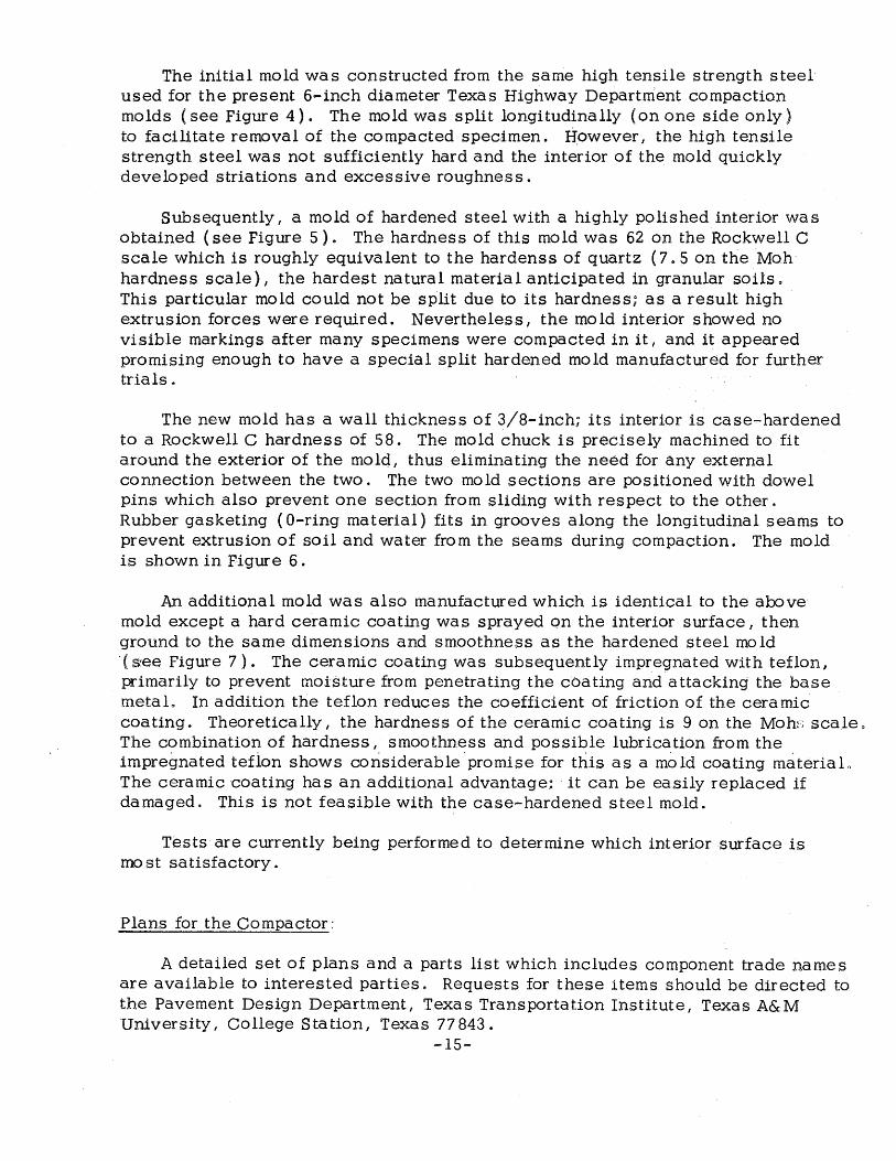
The new mold has a wall thickness of 3/8-inch; its interior is case-hardened to a Rockwell C hardness of 58. The mold chuck is precisely machined to fit around the exterior of the molql thus eliminating the need for any external connection between the two. The two mold sections are positioned with dowel pins which also prevent one section from sliding with respect to the other. Rubber gasketing ( 0-ring material) fits in grooves along the longitudinal seams to prevent extrusion of soil and water from the seams during compaction. The mold is shown in Figure 6.
An additional mold was also manufactured which is identical to the above mold except a hard ceramic coating was sprayed on the interior surface, then ground to the same dimensions and smoothness as the hardened steel mold (see Figure 7). The ceramic coating was subsequently impregnated with teflon, primarily to prevent moisture from penetrating the coating and attacking the base metaL In addition the teflon reduces the coefficient of friction of the ceramic coating. Theoretically I the hardness of the ceramic coating is 9 on the Moh}~ scale. The combination of hardness, smoothness and possible lubrication from the impregnated tefion shows considerable .promise for this as a mold coating materiaL The ceramic coating has an additional advantage: it can be easily replaced if damaged. This is not feasible with the case-hardened s tee 1 mold.
Tests are currently being performed to determine which interior surface is most satisfactory.
Plans for the Compactor:
A detailed set of plans and a parts list which includes component trade names are available to interested parties. Requests for these items should be directed to the Pavement Design Department I Texas Transportation Institute I Texas A& M University, College Station, Texas 77 843.
-15-
Figure 4: Split compaction mold initially used with the compactor ~igure 5: Hardened steel compaction mold
·Figure 6: Split surface hard~ned steel compaction mold
Figure 7: Split ceramic-lined compaction mold
5. COMPACTOR OPERATION
General
It is most convenient to place material in the mold after first removing the mold and base plate from the compactor.
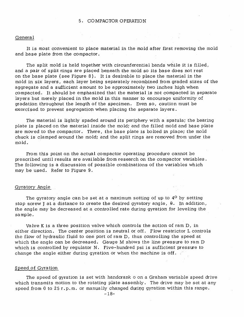
The split mold is held together with circumferential bands while it is filled I
and a pair of split rings are placed beneath the mold so its base does not rest on the base plate (see Figure 8). It is desirable to place the material in the mold in six layers I each layer being separately recombined from graded sizes of the aggregate and a sufficient amount to be approximately two inches high when compacted. It should be emphasized that the material is not compacted in separate layers but merely placed in the mold in this manner to encourage uniformity of gradation throughout the length of the specimen. Even so I caution must be exercised to prevent segregation when placing the separate layers.
The material is lightly spaded around its periphery with a spatula; the bearing plate is placed on the material inside the mold; and the filled mold and base plate are moved to the compactor. There, the base plate is bolted in place; the mold chuck is clamped around the mold; and the split rings are removed from under the mold.
From this point on the actual compactor operating procedure cannot be prescribed until results are available from research on the compactor variables. The following is a discussion of possible combinations of the variables which may be used. Refer to Figure 9 e
Gyratory Angle
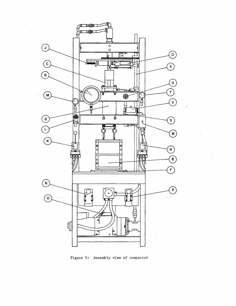
The gyratory angle can be set at a maximum setting of up to 4° by setting stop screw J at. a distance to .create the desired gyratory angle, Q. In addition I the angle may be decreased at a controlled rate during gyration for leveling the sample.
valve K is a three position valve which controls the action of ram D I in either direction. The center position is neutral or off. Flow restrictor L controls the flow of hydraulic fluid to one port of ram D 1 thus controlling the speed at which the angle can be decreased. Gauge M shows the line pressure to ram D which is controlled by regulator N. Five-hundred psi is sufficient pressure to change the angle either during gyration or when the machine -is off.
Speed of Gyration
The speed of gyration is set with handcrank o on a Graham variable speed drive which transmits motion to the rotating plate assembly. The drive may be set at any speed from 0 to 25 r.p. m. or manually changed durilJg gyration within this range.
-18-
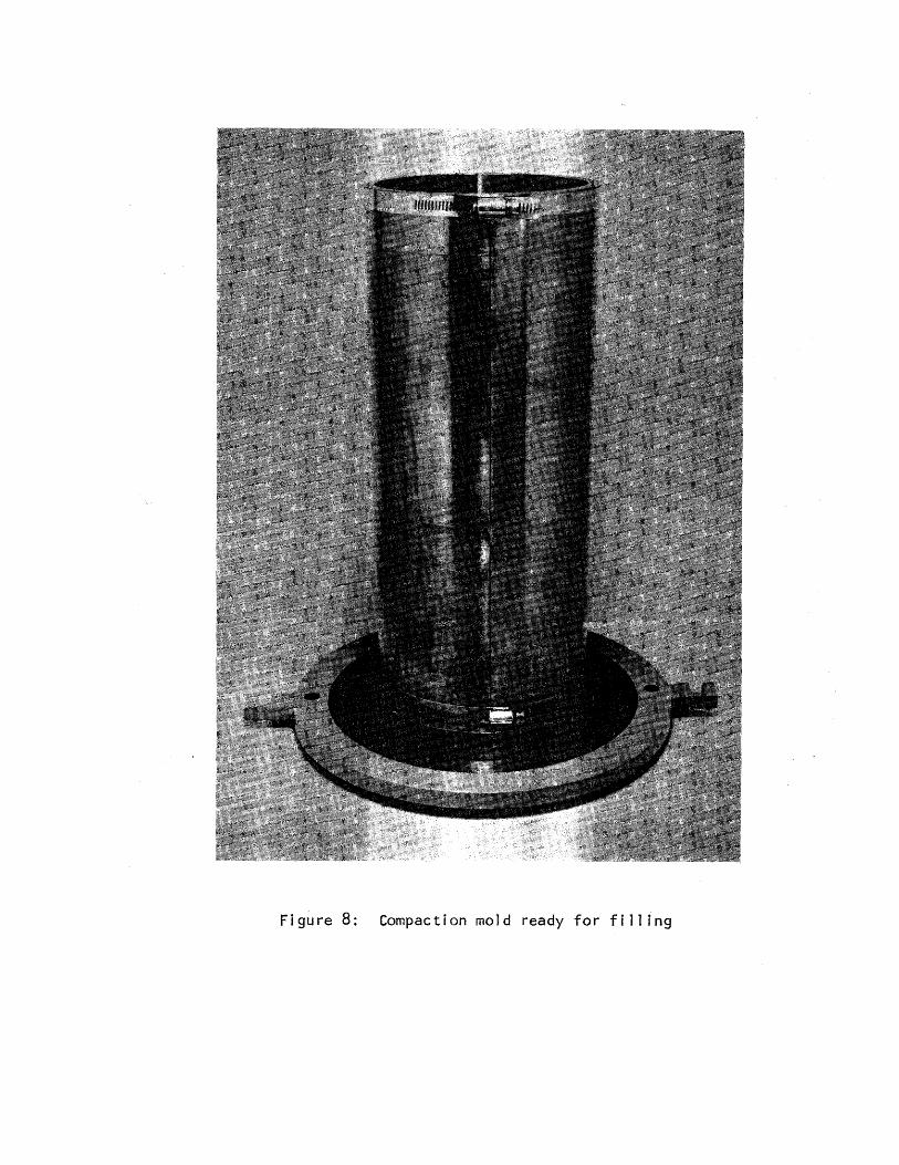
Figure 8: Compaction mold ready for filling
/
Figure 9: Assembly view of compactor
Vertical Load
A vertical load on the specimen is achieved with ram G. The hyqraulic pressure in ram G may be set from 0 to 600 psi with regulator P and accurately read on gauge Q. Valve R has three positions which control the direction of travel on ram. G .. Center position is neutral or off.
In addition, the rate of descent of ram G can be controlled by manipulating flow control valve S. When this arrangement is used full load is achieved on the specimen when downstream pressure gauge Q reads the same as upstream gauge T.
A fixed distance between the ends of the specimen can be maintained during gyration by closing valve U after an initial load has been applied.
Number of Revolutions
The desired number of gyrations for any given sample is set on counter V (a preset, predetermined revolution counter) so that when that number is reached, gyration ceases. Gyration is begun by turning switch W on.
Collection of Data
At the end of gyration, the vertic,al load is released, the mold chuck is released from the mold, and the base plate is unbolted from the frame. The entire base plate, mold and specimen are removed from the machine.
The split mold is then pulled away from the specimen, the height is measured, and the specimen is weighed. Specimens of granular material molded at high moi-sture contents may extrude water and Jines under high compactive efforts. This will be caught in the trough of the base plate; if desired, it may be recovered and also weighed.
By knowing the weight and dimensions of the molded ~pecimens I its molded density can be computed. The_ specimen is then ready for subsequent testing or for oven-drying if its molded moisture content and dry density are desired?
Discussion of Variables
To determine the most effective procedure certain variations remain to be tried. In particular, the sequence of applying the vertical pressure and gyratory action, and the number of gyrations required to level the specimen I need additional study. So far, attempts have been made to a) apply the full vertical pres sure before initiating
-21-
gyratory action I b) simultaneoulsy apply the full vertical pressure and initiate gyratory action I and c) allow the vertical pressure to slowly increase from zero to the desired maximum as gyration proceeds. The rate at which the vertical pressure increases can be controlled either with valve S, with pressure regulator P, or by a combination of both.
The rate at which the specimen should be leveled is apparently a function of the strength of the specimen. One of high strength may require several gyrations while a weaker specimen may require only a few gyrations.
In general, these are techniques which must be examined in detail and it is quite possible that different variations will be required with different materials.
Operation of the Compactor as a Variable Strain Apparatus
When the compactor is used with a constant gyratory angle it is a fixed strain apparatus. However, it is possible to adjust the regulator, N, (see Figure 9) at a low enough pressure so that the resistance of the specimen to gyration will overcome the force exerted by ram D, thereby producing a tendency for the specimen to decrease its gyratory angle and even to level itself up,. The resistance to gyration is a function of the strength of the specimen 1 thus it represents a means whereby the compactor may also serve as a testing or strength measuring device, particularly for applications involving repeated loading,.
Variation of the pressure governing the gyratory angle is· the fifth machine variable mentioned earlier in the report. (It should be mentioned that the Waterways Experiment Station gyratory compactor can also be adjusted so it performs a similar function. ) Although this is a by-product of the ·original design 1
it appears to have great potential for evaluating strength characteristics under repeated shear and it warrants further investigation.
Measurement of Compactive Effort
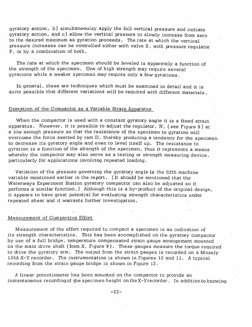
Measurement of the effort required to compact a specimen is an indication of its strength characteristics. This has been accomplished on the gyratory compactor by use of a full bridge I temperature compensated strain gauge arrangement mounted
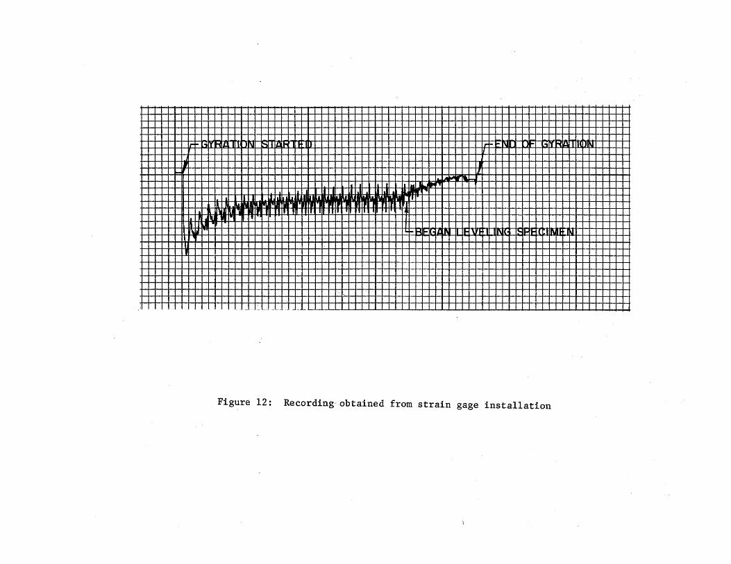
·on the main drive shaft (Item X, Flgure 9). These gauges measure the torque required to drive the gyratory arm. The output from the strain gauges is recorded on a Mosely l36A X-Y recorder. The instrumentation is shown in Figures 10 and 11. A typical recording from the strain gauge bridge is s:hown "in Figure 12.
A linear potentiometer has been mounted on the compactor to provide an instantaneous recording of ·tjhe specimen height on theX-Yrecorder o In addition to knowing
-22-
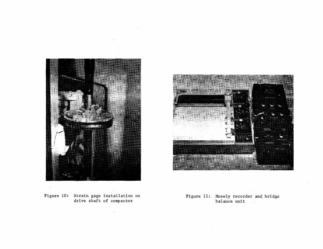
Figure 10: Strain gage installation on drive shaft of compactor
Figure 11: Mosely recorder and bridge balance unit
lr~ ~IY Hit: IJN ~· Ill.~ tH lr- ~N 1- L-IT t"CU IIU Jl~ IJ
IJI I - L Ia. A ~r 1'-~-o
Ia• I ~H't
~~ ~~-· a a 1111'1r ..
l I •• N~ 'I
II. II PI I ll I l 1111 Ul Jll'l II 1 1 r I t
11 .Jil "'"'I . ' .
ftJirl I\ I 1- ... , rt I 1\ll !~II- it'll 111\j n n1
' -
··-.
; ·-·. ---- -··-- - -·-
Figure 12: Recording-obtained from strain gage installation
how high the specimen is at any time, simultaneous records of specimen height and applied compactive effort should provide vital information for a better understanding of the relationship between compactive effort, density, and perhaps, strength of granular materials.
-25-
6.. DESIGN PROBLEMS- AND RECOMMENDATIONS FOR FUTURE MODELS
Because the actual compactive energy could not be predetermined! the compactor was, of necessity, constructed without knowledge of the forces involved. After initial trials, it was obvious that some components were overdesigned and that others needed strengthening. In particular, revisions were necessary in the gyratory drive unit and in the main hydraulic ram which applies the vertical load.
The variable speed drive, as received, did not provide sufficient torque to gyrate specimens at low speeds when high vertical pressures were used. Two gear reduction units of 10:1 ratio each, connected in series and then attached to the output shaft of the variable speed drive, have eliminated this problem. Two units were used mainly because they were readily available; a single Graham variable speed drive of 0 to 3 0 r. p. m & output, mounted vertically, would be more desirable G This would also conserve more space beneath the compactor table o
Before the upper frictionless assembly was perfected, the lateral forces transferred to the main hydraulic ram were quite high. Not only did these forces produce excessive flexure in the ram piston, but also they threatened to damage the bushings and seals. This was remedied by replacing the original piston with a high-yield strength steel of increased diameter, and by installing a linear ball bushing in the ram for the piston to travel through$ These modifications were necessary because standard hydraulic rams are not designed to w'ithstand such large lateral forces.
The over-all dimensions of the compactor are quite large and they could be reduced, particularly the heighL This could be done by inverting the rotating plate unit and gyrating arm so that the rotating plate would be located beneath the compaction table. This would also simplify power transmission from the variable speed drive to the rotating plate. In addition, the main hydraulic ram might be placed benea~h the ~ompaction table :where _it would apply pr~ssure_ against the base plate rather than at the top of the specimen.
Another modification would be the substitution of 1/ 4-inch hydraulic lines throughout the compactor in place of the present 3/8-inch lines. This should still provide ample fluid volume and would greatly reduce the cost and size of pressure regulators and valves.
-26-
7. CONCLUSIONS
The gyratory compactor reported herein was developed specifically for molding 6-inch diameter by 12-inch high specimens of granular materials for repetitive triaxial testing. Although the test results are limited at present, the compactor appears capable of achieving its design requirements as stated earlier in the report. The compactor has several variables which can be altered to produce a desired combination of dry unit weight and moisture content. A detailed investigation is now in progress to determine the influence of each of these variables on the compaction characteristics of granular materials. Presently, replicate specimens can be molded with a variation of less than 0. 5 pcf in their densities.
One of the most encouraging facets of the compactor is its ability to mold specimens of granular materials without apparent segregation. This is well illustrated in Figures 13 and 14, which show cement- stabilized specimens which were sawed after curing. The top picture is typical of a specimen molded by the impact procedure: coarse aggregate is located in the middle of each layer and an obvious layering effect is visible. The lack of coarse aggregate near the handfinished surface is also evident. Certainly this has a significant effect on both the compaction and stress-strain characteristics of the material. On the other hand, the lower picture of a gyratory compacted specimen which indicates no layers or segregation of the material. In addition, the elongated particles are oriented horizontally, consistent with observations on similar materials compacted in the field.
While the apparatus was designed for a specific purpose, it appears to have many other applications. As indicated earlier in the report it may have use as a device for measuring the ability of materials to withstand repetitive loading. Its use is not restricted to granular materials and, with modifications, it can be used to fabricate other specimen sizes & For example, it has successfully molded 6 -inch by 12-inch asphaltic concrete specimens and 6-inch by 8-inch Texas triaxial specimens of granular materials.
-27-
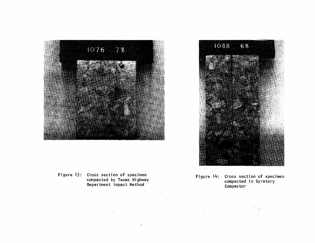
Figure 13: Cross section of specimen· compacted by Texas Highway Department lmp.act Method
Figure 14: Cross section of specimen compacted In Gyratory Compactor
REFERENCES
1. Al-Lay la, M. T. H. , "Effect of Compaction Method on the C BR Value for Crushed Gravel," unpublished M.s. Thesis, Texas A&M University, College Station, Texas, 1966.
2. Dunlap, Wayne A., "Deformation Characteristics of Granular Materials S ubj ,ected to Repetitive Triaxial Loading, " ~es.earch Report 2 7-4, .· Texas Transportation Institute~ College Station, 'texa,s, 1966.
3. Foster, C. R., "Field Problems: Compaction," Cha'pter 12; Foundation Engineering, edited by G ~ A. Leonards I McGraw~ Hill Company, New York, 1962.
4. Johnson, A. W. and Guinee, J. W. I "A Study of ~arthwprk Compaction, " Highway Research Board, National Academy of Sei'e:hces .:. National Research Council, Washington, D. C., May, l96~f.,
5. Johnson, A. W. and J. R. Sallberg, "Factors Influen,ping Compaction Test Results," Highway Research Board Bulletin :No. '319, NationalAc.ademy of Sciences - National Research Council, Washington, D. C., 1962.
6. Kimble, F. w. and Gibboney, w. B. I "Control ofFieHd Density of Bituminious Concrete with a Gyratory Compactor ,··• Proceedings, Association of Asphalt Paving Technologists·~ Ann Arbor, Michigan, February, 1961.
7. McRae, J. 1 .. , personal communication, Oct. 1, 1965·0
8. Parsons, W. H., "Compaction Characteristics of Crushed Limestone Using the Gyratory Testing Machine I" unpublished. NL S Thesis I Texas A& M University, College Station I Texas, 1963.
9. U. S. Army Engineer Waterways :B:xperiment Station, Corps of Engineers, Technical Memorandum ·3-271, Vicksburg I Mississippi~ A series of 9 reports.
10. U. S. Army Engine~r Waterways Experiment Station:, ,corps of Engineers, Technical Report 3-595 I Vicksburg I Mississippi:; Fe~ruary, 1·9()2 ..
11. Wilson I S. D., "Small Soil Compaction Apparatus Duplicates Field Results Closely," Engineering News-Record, Vol .. 145, No.·18,·. November 2, 1950.
-29-


![GB5 mix design high-performance - Sabita...- Compacting ability [NF EN 12697-31]: Gyratory compactor - Moisture resistance [NF EN 12697-12]: Duriez test - Rutting resistance at 60°C](https://img.pdfslide.net/doc/110x75/60c8683095d8fe32f1212707/gb5-mix-design-high-performance-compacting-ability-nf-en-12697-31-gyratory.jpg)