Embed Size (px)
Citation preview

5.1 Optical sensors
5.1.1 Introduction
This term is applied to those classes of gyroscope which use the properties of electro-magnetic radiation to sense rotation. Such devices often use the visible wavelengths,but it is also possible to operate in the near infrared. Some mechanical gyroscopes useoptical angle pick-off sensors, but for this discussion they are not classed as opticalgyroscopes. Optical gyroscopes use an interferometer or interferometric methods tosense angular motion. In effect, it is possible to consider the electromagnetic radiationas the inertial element of these sensors.
It was during the late nineteenth century that Michelson pioneered work withoptical interferometers, although his goal was not to produce an optical gyroscope.In 1913, the Sagnac effect was reported [1] and this is the fundamental principle onwhich optical gyroscopes are based. When light travels in opposite directions (clock-wise and anti-clockwise) around an enclosed ring, differences arise in the apparentoptical length of the two paths when the ring is rotated about an axis orthogonal to theplane containing the ring. In 1925, this concept was applied by Michelson and Gale [2]in Chicago using a ring gyroscope with a perimeter of over one mile. By sendingordinary light through evacuated water pipes, they were able to detect the shiftproduced by the rotation of the Earth.
Further impetus to produce an optical sensor resulted from the demonstration ofa laser by Maiman in 1960 [3]. These devices produce a well collimated and highlymonochromatic source of electromagnetic energy between the ultraviolet and farinfrared part of the spectrum, the wavelength being determined by the laser medium.In 1963, the first ring laser was demonstrated by workers at Sperry Gyroscope [4].This marked the beginning of the development of the ring laser gyroscope. Abouta decade later the fibre optic gyroscope was first demonstrated [5].
Clearly, the history of the development of optical gyroscopes is far more recentthan the history of the mechanical sensors. Further impetus for the development of
Chapter 5
Gyroscope technology 2
these sensors, besides the development of the laser, was the interest in the applicationof strapdown technology and the desire to capitalise on the benefits anticipated fromthe use of solid-state inertial sensors. One of the main difficulties in the application ofstrapdown technology from the point of view of gyroscope performance was the lackof adequate dynamic range of the mechanical sensors for the more accurate applica-tions. Initial estimates of performance suggested that the ring laser gyroscope couldprovide the solution.
The spectrum of performance of optical gyroscopes ranges from the very accuratewith bias of less than 0.00 l°/h, usually ring lasers, to tens of degrees per hour, oftenfrom the simpler fibre optic gyroscopes. Hence the range covered by the opticaldevices is very similar to that covered by the mechanical gyroscopes. Generally,all the types of optical gyroscopes are suitable for various strapdown applications,depending of course on the demanded accuracy of the system.
It appears that the application of optics to the sensing of angular rate can offera number of advantages over the use of the well-established mechanical technology.Some of the advantages often cited are listed below:
1. wide dynamic range;2. instant start-up;3. digital output;4. output independent of some environmental conditions (acceleration, vibration
or shock);5. high rate capability;6. easy self-test;7. system design flexibility;8. extended running life.
5.1.2 Fundamental principles
Optical gyroscopes rely upon the detection of an effective path length differencebetween two counter-propagating beams of light in a closed path. The mathematicaldevelopment given here shows how this path difference arises in the presence of anapplied turn rate about an axis perpendicular to the plane containing the light path.
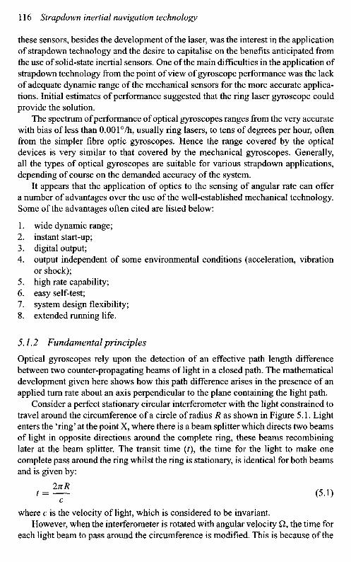
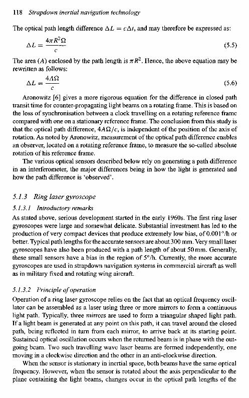
Consider a perfect stationary circular interferometer with the light constrained totravel around the circumference of a circle of radius R as shown in Figure 5.1. Lightenters the 'ring' at the point X, where there is a beam splitter which directs two beamsof light in opposite directions around the complete ring, these beams recombininglater at the beam splitter. The transit time (t), the time for the light to make onecomplete pass around the ring whilst the ring is stationary, is identical for both beamsand is given by:
-ZZ (5.0C
where c is the velocity of light, which is considered to be invariant.However, when the interferometer is rotated with angular velocity £2, the time for
each light beam to pass around the circumference is modified. This is because of the

Figure 5.1 Circular rotating (Sagnac) interferometer
motion of the beam splitter during the time taken for the light to pass around the ring.As shown in the figure, the beam splitter will have moved to position Y. Therefore,light travelling in a clockwise direction will have to travel further than the distancetravelled when stationary. The converse is also true for the anticlockwise beam. Moregenerally, with respect to inertial space, light travelling with the direction of rotationmust travel further than when the interferometer is stationary. Light travelling againstthe direction of rotation will have its path length reduced when compared with thestationary condition. Hence, the single pass transit time for the two beams is givenby the following equations.
Clockwise path, t\ =C (5.2)
A - I i . 1. InR-AL-Anti-clockwise path, t2 =c
Now, AL+ = RQt\ and AL_ = RQt2 are the increment and decrement in thepath length respectively. As reported by Aronowitz [6], this can also be interpretedas the velocity of light being different for the two counter-propagating beams and thepath length being invariant.
From the above equations, the difference in transit time, At, is given by:
At = t1-t2= 2TTR \ l— - —^—1 (5.3)lc — QR c + QR J
To first order approximation, this becomes:
AnR2QAt = j — (5.4)
The optical path length difference AL = cAt, and may therefore be expressed as:
AL = ^ (5.5)C
The area (A) enclosed by the path length is TtR2. Hence, the above equation may berewritten as follows:
AL = I ^ (5.6)C
Aronowitz [6] gives a more rigorous equation for the difference in closed pathtransit time for counter-propagating light beams on a rotating frame. This is based onthe loss of synchronisation between a clock travelling on a rotating reference framecompared with one on a stationary reference frame. The conclusion from this study isthat the optical path difference, 4AQ/c, is independent of the position of the axis ofrotation. As noted by Aronowitz, measurement of the optical path difference enablesan observer, located on a rotating reference frame, to measure the so-called absoluterotation of his reference frame.
The various optical sensors described below rely on generating a path differencein an interferometer, the major differences being in how the light is generated andhow the path difference is 'observed'.
5.1.3 Ring laser gyroscope
5.1.3.1 Introductory remarks
As stated above, serious development started in the early 1960s. The first ring lasergyroscopes were large and somewhat delicate. Substantial investment has led to theproduction of very compact devices that produce extremely low bias, of 0.001 °/h orbetter. Typical path lengths for the accurate sensors are about 300 mm. Very small lasergyroscopes have also been produced with a path length of about 50 mm. Generally,these small sensors have a bias in the region of 5°Ih. Currently, the more accurategyroscopes are used in strapdown navigation systems in commercial aircraft as wellas in military fixed and rotating wing aircraft.
5.1.3.2 Principle of operation
Operation of a ring laser gyroscope relies on the fact that an optical frequency oscil-lator can be assembled as a laser using three or more mirrors to form a continuouslight path. Typically, three mirrors are used to form a triangular shaped light path.If a light beam is generated at any point on this path, it can travel around the closedpath, being reflected in turn from each mirror, to arrive back at its starting point.Sustained optical oscillation occurs when the returned beam is in phase with the out-going beam. Two such travelling wave laser beams are formed independently, onemoving in a clockwise direction and the other in an anti-clockwise direction.
When the sensor is stationary in inertial space, both beams have the same opticalfrequency. However, when the sensor is rotated about the axis perpendicular to theplane containing the light beams, changes occur in the optical path lengths of the

two beams. The frequency of each beam changes to maintain the resonant conditionrequired for laser action such that the frequency of the beam with the longer path lengthdecreases whilst the frequency of the other beam increases. This path difference is verysmall, no more than 1 nm, thus a source with high spectral purity and stability, suchas a helium-neon gas laser, is required to make the laser gyroscope concept feasible.
Maintenance of laser action requires a constant phase at a given mirror surfaceafter every round trip in order to maintain the resonant condition.
Hence, if La is the anti-clockwise path length and Lc the clockwise path length,then the resonant condition is given by:
L;=pk; (5.7)L0 = pkc
where p is the mode number, typically of the order of a million, and A.a and Xc arethe two wavelengths of laser energy. When this interferometer is rotated at a rate £2,these path lengths differ and are given by:
2AQL/% — /?Aa — L i
° (5.8)2AQ.
LC = /7AC = LC
where L is the perimeter length and the path difference AL = 4AQ/c.Now if va and vc are the optical frequencies of the two beams, vaAa = ^ c = c.
Substituting for wavelength in the above equations, we have,
V3 = ^ and vc = ^ (5.9)^a L c
Hence, small changes in path length result in small changes in frequency, Av, givenby the relation,
^ = ^ (MHv L
Substituting for AL in this equation, this beat frequency can be expressed as:
AAQ 4AQA v = - — v = — — (5.11)
cL Lkwhere
. K + A-c , Va + Vc
X = — - — and v = — - — (5.12)
It follows from eqn. (5.11) that the turn rate (Q) may be determined from the frequencydifference (A v) generated in its presence. The scale-factor of the sensor is directly pro-portional to the area (A) enclosed by the optical path. Changes in A result from varia-tions in the cavity length. Use of active laser gain control and cavity path length controlusually contain these excursions to a few parts per million or less for most designs.
Substitution of typical values into eqn. 5.11 shows the beat frequency to be froma few hertz up to megahertz. This beat frequency can be detected, even for very slow
rotation rates. As noted by Aronowitz, thermal and mechanical instabilities can causefrequency variations in the individual beams that are far greater than the rotationalbeat frequency, as can be deduced from eqns. (5.9)—(5.11). The successful operationof this type of sensor is achieved since both beams occupy the same laser cavity andtherefore are subject to identical perturbations.
In order to detect the rotational motion, a small amount of light from each beamis allowed to 'escape' through one of the mirrors, known as the output mirror, andthe two beams are combined using a prism to form an interference pattern on aset of photo-diodes. The frequency difference between the two beams causes theinterference fringes to move across the detectors at a rate equal to the difference infrequency between the two beams which is also proportional to the rotational motion.
Hence, the movement of a single fringe past the detector corresponds to anincremental rotation, A0, where,
A*=£ (5.13)
This equation can be used to determine the sensitivity of a ring laser gyroscope. Fora device having an equilateral triangular path of total length L, the area is given by:
1 /L\2
A = - I - sin 60° (5.14)2 \ 3 /
Substituting in the preceding equation, it can be shown that the sensitivity is inverselyproportional to the path length, viz.
A O = ^ (5.15,
For instance, considering a helium-neon laser in which the optical wavelength is0.6328 |xm (632.8 nm), the sensitivity of a 30 cm path length device is 2.25 arcsper fringe. For the smallest ring caser gyroscope, with a 50 mm path length, thesensitivity is 13.5 acrs per fringe.
5.1.3.3 The lock-in phenomenon
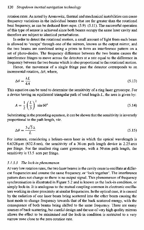
At very low rotation rates, the two laser beams in the cavity cease to oscillate at differ-ent frequencies and assume the same frequency, or iock together'. The interferencepattern does not change so there is no output signal. This phenomenon of frequencysynchronisation is illustrated in Figure 5.2 and is known as the lock-in condition, orsimply lock-in. It is analogous to the mutual coupling common in electronic oscilla-tors working in close proximity at similar frequencies. In the optical case, it is causedby the radiation of one laser beam being scattered into the other beam causing thehost mode to change frequency towards that of the back scattered energy, with theconsequence of both beams being shifted to the same frequency. There are manysources of back scattering, but careful design and the use of very high quality mirrorsallows the effect to be minimised and the lock-in condition is restricted to a verynarrow zone close to the zero rotation rate.

Figure 5.2 Laser gyroscope input/output characteristic
Alleviation of lock-inOne of the most common methods used to alleviate the lock-in problem is the use ofmechanical oscillation. Mechanical dithering consists of applying angular vibrationsto the entire cavity at high frequency but at low amplitude and through small angles,thereby avoiding low frequency outputs. Through the use of a so-called large ditherproduct (dither frequency multiplied by the amplitude), having a high frequencymotion but small displacement, very little time is spent by the sensor in the lock-inregion, hence greater accuracy is achieved through missing fewer pulses.
The dither frequency has a random frequency component superimposed on itwhich randomises slightly the motion of the cavity. The result of this randomisationis that the motion has a randomised rate noise rather than a mean bias which wouldbe produced by a sinusoidal motion of the cavity block [7]. This motion producesa random walk in angle which appears on the output of the sensor.
The use of mechanical dither causes an increase in size, weight and complexity.It is necessary to subtract the dither motion from the gyroscope's output and this maybe accomplished either optically or electronically. Any difference between the actualand compensated output is termed dither spill over which leads to a scale-factor error.
Another technique that is currently being applied is called magnetic mirrorbiasing. This electro-optical technique uses a non-reciprocal magneto-optical effect(the transverse Kerr effect [8]). One of the highly reflective mirrors has a magneticcoating on its top surface. The magnetic coating, when saturated by an applied mag-netic field, causes a difference in phase delay between the two counter-propagating
Key:Q1=Lock-in rate
Output beamfrequencydifference
Input rate
Lock-in region
laser beams, biasing the frequencies away from the lock-in zone. In order to preventany drifts in bias voltage being interpreted as a rotation rate, it is necessary to switchbetween two bias points so any drifts average to zero. A potential disadvantage withmagnetic mirrors is the introduction of higher cavity losses which may exclude it fromhigh accuracy applications. However, it is a genuine solid-state sensor [9] which issmaller and less complex than the mechanically dithered ring laser gyroscope.
Multi-oscillator concepts have been demonstrated [10-12] where more than asingle pair of beams propagate in the same cavity, usually four beams in a squareconfiguration. Independent lasing of left and right polarised modes are propagated ineach direction in the cavity, giving a total of four modes. Avoiding the phenomenonof lock-in still applies, so it is necessary to bias the modes away from this zone. Thereciprocal splitting between the right-hand and left-hand circularly polarised modescan be several hundred megahertz, achieved by using a quartz retarder plate, or a non-planar cavity configuration. The real difficulty is to achieve adequate biasing of thedirection dependent (non-reciprocal) modes, that is, the clockwise and anti-clockwiseright-hand circularly polarised modes, and similarly with the opposite handed modes.
Three methods have shown promise: use of a Faraday rotation element in the lasercavity; a mirror with a magneto-optic coating that uses either the polar or transverseKerr effect; application of a Zeeman field to the discharge to induce a frequencychange. Sometimes the ring laser gyroscope that has a Faraday cell in its cavity iscalled the differential laser gyroscope or DILAG; the other name is the four-frequencygyroscope. One distinct advantage that this form of gyroscope has over the conven-tional ring laser gyroscope is an enhanced scale-factor; giving a sensitivity that istwice that of the equivalent sized conventional laser gyroscope.
5.1.3.4 Detailed description of the sensor
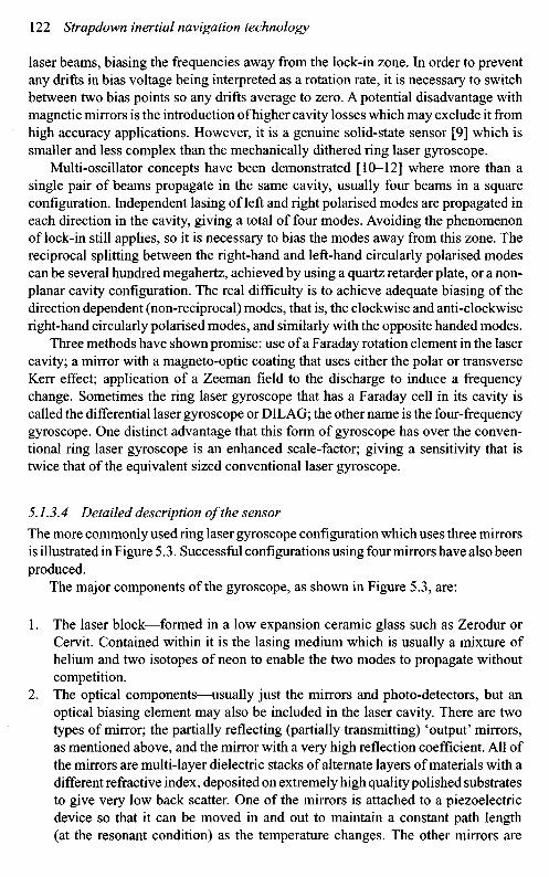
The more commonly used ring laser gyroscope configuration which uses three mirrorsis illustrated in Figure 5.3. Successful configurations using four mirrors have also beenproduced.
The major components of the gyroscope, as shown in Figure 5.3, are:
1. The laser block—formed in a low expansion ceramic glass such as Zerodur orCervit. Contained within it is the lasing medium which is usually a mixture ofhelium and two isotopes of neon to enable the two modes to propagate withoutcompetition.
2. The optical components—usually just the mirrors and photo-detectors, but anoptical biasing element may also be included in the laser cavity. There are twotypes of mirror; the partially reflecting (partially transmitting) 'output' mirrors,as mentioned above, and the mirror with a very high reflection coefficient. All ofthe mirrors are multi-layer dielectric stacks of alternate layers of materials with adifferent refractive index, deposited on extremely high quality polished substratesto give very low back scatter. One of the mirrors is attached to a piezoelectricdevice so that it can be moved in and out to maintain a constant path length(at the resonant condition) as the temperature changes. The other mirrors are
Read-outdetector
Partiallytransmitting
mirror
Anode
Cornerprism
Counter-propagatinglaser beams
Anode
Ceramicblock
Mirror(very high R)
Pathlengthcontrol
transducer
Dither wheel
CathodeMirror
(partially transmitting)
Pathlengthcontrol
detector
Figure 5.3 Schematic diagram of a ring laser gyroscope
firmly bonded directly to the laser block. A variety of techniques are used includ-ing optical contacting, using soft metal seals such as gold and indium, and analternative bonding technique known as frit sealing.
3. The non-optical components—the usual configuration is to have one cathode andtwo anodes which produce a discharge when a high voltage is applied to theseelectrodes. This discharge then provides the source of excitation for the laseraction. The usual laser wavelengths that are used are either the red line at 632.8 nmor the 1.152 |xm line in the infrared part of the electromagnetic spectrum.
4. The biasing mechanism required to overcome the lock-in phenomenon describedin detail above. A bias can be applied by various techniques such as mechanicaldither, magnetic mirror or the use of optical elements within the laser cavity.
A photograph of a mechanically dithered ring laser gyroscope is shown inFigure 5.4.
The primary disadvantage of this technology is the precision engineering that isrequired to make and polish the faces of the laser block and the high technologyrequired to produce the mirrors. This tends to make the cost of the sensor quite high,although techniques for reducing this are being sought. A further anticipated problemis the potential for helium to leak out of the cavity through one of the many seals.Radio frequency pumping of the laser cavity has been demonstrated and is a methodof reducing the number of components fitted into the block and hence reducing thenumber of orifices and seals through which this gas can leak.
Mirror quality assessment prior to assembly of the sensor is crucial to theperformance and yield achieved in production of these devices. It is usual to evaluate
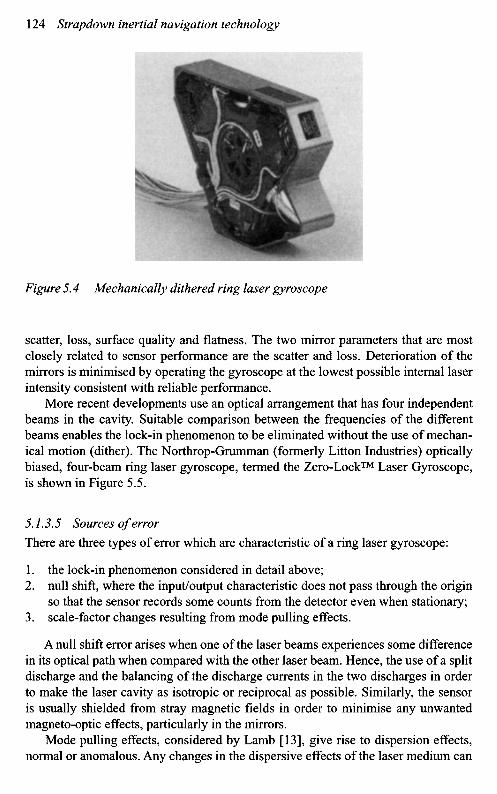
Figure 5.4 Mechanically dithered ring laser gyroscope
scatter, loss, surface quality and flatness. The two mirror parameters that are mostclosely related to sensor performance are the scatter and loss. Deterioration of themirrors is minimised by operating the gyroscope at the lowest possible internal laserintensity consistent with reliable performance.
More recent developments use an optical arrangement that has four independentbeams in the cavity. Suitable comparison between the frequencies of the differentbeams enables the lock-in phenomenon to be eliminated without the use of mechan-ical motion (dither). The Northrop-Grumman (formerly Litton Industries) opticallybiased, four-beam ring laser gyroscope, termed the Zero-Lock™ Laser Gyroscope,is shown in Figure 5.5.
5.1.3.5 Sources of error
There are three types of error which are characteristic of a ring laser gyroscope:
1. the lock-in phenomenon considered in detail above;2. null shift, where the input/output characteristic does not pass through the origin
so that the sensor records some counts from the detector even when stationary;3. scale-factor changes resulting from mode pulling effects.
A null shift error arises when one of the laser beams experiences some differencein its optical path when compared with the other laser beam. Hence, the use of a splitdischarge and the balancing of the discharge currents in the two discharges in orderto make the laser cavity as isotropic or reciprocal as possible. Similarly, the sensoris usually shielded from stray magnetic fields in order to minimise any unwantedmagneto-optic effects, particularly in the mirrors.
Mode pulling effects, considered by Lamb [13], give rise to dispersion effects,normal or anomalous. Any changes in the dispersive effects of the laser medium can
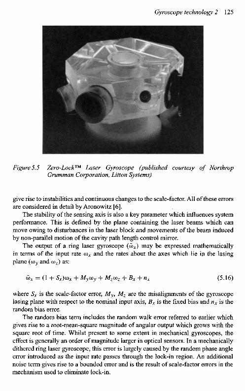
Figure 5.5 Zero-Lock™ Laser Gyroscope (published courtesy of NorthropGrumman Corporation, Litton Systems)
give rise to instabilities and continuous changes to the scale-factor. All of these errorsare considered in detail by Aronowitz [6].
The stability of the sensing axis is also a key parameter which influences systemperformance. This is defined by the plane containing the laser beams which canmove owing to disturbances in the laser block and movements of the beam inducedby non-parallel motion of the cavity path length control mirror.
The output of a ring laser gyroscope (65J may be expressed mathematicallyin terms of the input rate GO* and the rates about the axes which lie in the lasingplane (a)y and ooz) as:
tix = (1 + Sx)Vx + My(Oy + Mzcoz + Bx + nx (5.16)
where Sx is the scale-factor error, My, Mz are the misalignments of the gyroscopelasing plane with respect to the nominal input axis, Bx is the fixed bias and nx is therandom bias error.
The random bias term includes the random walk error referred to earlier whichgives rise to a root-mean-square magnitude of angular output which grows with thesquare root of time. Whilst present to some extent in mechanical gyroscopes, theeffect is generally an order of magnitude larger in optical sensors. In a mechanicallydithered ring laser gyroscope, this error is largely caused by the random phase angleerror introduced as the input rate passes through the lock-in region. An additionalnoise term gives rise to a bounded error and is the result of scale-factor errors in themechanism used to eliminate lock-in.
5.1.3.6 Typical performance characteristics
With careful design, this form of gyroscope does not exhibit any significant acceler-ation or vibration sensitivity. The typical range of performance that can be achievedfrom these devices is as follows:
^-Independent drift (bias)g-Sensitive biasg2-Sensitive biasScale-factor errors
BandwidthMaximum input rateRandom walk
<0.001-10°/hUsually insignificant for most applicationsUsually insignificant for most applicationsFew parts per million to 0.01%
(of maximum rotation rate)>200 Hz (can be made very large)Several thousand degrees per second0.001-0.01°/h
Hence, the key parameters are the bias repeatability, random noise, scale-factorrepeatability and sensing axis stability.
5.1.4 Three-axis ring laser gyroscope configuration
Various schemes have been proposed and implemented to produce a single sensorwith three sensitive axes using ring laser technology. Such devices are commonlycalled triads. These configurations are generally based on the use of three mutuallyorthogonal square laser cavities within a single cubic block. This arrangement enableseach mirror to be shared by two of the laser cavities so only six mirrors are requiredfor this device [14]. Similarly, the cathode is shared between discharges. The use ofmechanical dither, applied about a body diagonal of the laser block, enables a biasto be applied simultaneously to each of the individual sensors within the monolith,and hence alleviate the lock-in problem for each of the axes.
Use of such a configuration can be very attractive for a number of applications as itprovides great stability between the axes. The cost and complexity can also be reducedcompared with the use of three independent sensors by using one dither mechanism,one discharge circuit and reducing the number of mirrors required through sharing.
The major disadvantage of such a system is the care needed and difficulty inmachining the laser block to the necessary accuracy as well as avoiding damageduring production, that is, achieving a high yield. Additionally, a single fault couldmean that all three axes of angular motion information is lost.
A schematic diagram of a triad is shown in Figure 5.6.
5.1.5 Fibre optic gyroscope
5.1.5.1 Introductory remarks
Work at the US Naval Research Laboratories in the late 1960s suggested that multiplecirculations of a Sagnac interferometer may give sufficient sensitivity to enableangular rotation to be detected and measured. By the mid-1970s, research progressed

Key:Laser path (axis 1)Laser path (axis 2)Laser path (axis 3)
Inputaxis 3
Anode
Outputmirror
Detector
Pathlengthcontrolmirror
A Input• axis 1
Ditheraxis
Inputaxis 2
Cathode
Pathlengthcontrolmirror
Combinerprism Anode
withfill tube
Figure 5.6 Schematic diagram of a triad
significantly on the use of passive interferometric techniques to sense angular motion,by applying optical fibre technology to form the light path [5]. This approach wasseen as offering a far cheaper alternative to the ring laser technique, as the needto machine and polish surfaces to fractions of an optical wavelength would not berequired. However, it was recognised that this approach was thought unlikely to pro-duce a sensor with true high performance inertial performance characteristics, that is,drift values in the region of 0.01°/h or better. Application of modern technology andtechnique has enabled this goal to be achieved.
In contrast with the ring laser technology, the fibre optic gyroscope senses angularmotion by detecting the phase difference between the two beams passing round thelight path in opposite directions. The gyroscope can be constructed as a genuine solid-state sensor, even in a closed loop mode, by the use of integrated optical components(chips). Use of this technology means that this type of inertial instrument can be verycompact. However, extreme care and good design is required with the necessary fibreconnections to avoid failure in harsh environments. Currently this is the subject ofvarious research projects in many parts of the world [15].
These sensors have found many applications, particularly in the roboticsand automobile industries. Aerospace applications are developing, especially forstabilisation and inertial navigation.
5.1.5.2 Principle of operation
Operation of the fibre optic gyroscope is dependent on the formation of a Sagnacinterferometer [16]. In its simplest form, light from a broad band source is splitinto two beams that propagate in opposite directions around an optical fibre coil.
These two beams are combined at a second beam splitter to form an interferencepattern where the resultant intensity is observed using a photo-detector. When theinterferometer is stationary, the path length of the two counter-rotating beams isidentical so there is no phase difference resulting in maximum amplitude. However,when the fibre coil is rotated about an axis normal to the fibre coil, the light travellingin the same direction as the rotation travels slightly further than the light travelling inthe opposing direction. The resulting phase difference results in a change in amplitudeof the interference pattern formed when the two beams are recombined.
For a rotating fibre gyroscope with a single turn of fibre, the phase difference(AO) between the counter-propagating beams of light may be expressed in terms ofthe path difference (AL) generated when the device rotates as:
A O = 2 T T — (5.17)A
Substituting for AL from eqn. (5.6) gives:
SnAQAO = (5.18)
ck
where A is the area enclosed by the fibre coil, £2 is the applied rotation rate andc is the velocity of light.
For a coil of TV turns, this becomes:
STTANQA<t> = (5.19)
cX
This may be expressed in terms of the length of the fibre (L = 2nRN) as:
4nRLQAO = (5.20)
ck
Consider a coil of radius 40 mm containing a 100 m length of fibre. If the opticalwavelength is 850 nm, the phase differences which occur for rotation rates of (a) 15°/hand (b) 5007s are as follows:
(a) AO = 0.0008°
(b) AO = 98.6°
Clearly, if a sensor is going to be capable of detecting Earth's rate or comparablerotations, a high level of dimensional stability will be necessary. Hence, light trav-elling one way around the fibre coil must travel exactly the same path as the lightwhich travels in the opposite direction, that is, reciprocity must be maintained.
Comparing this equation with eqn. 5.11 for the ring laser gyroscope, the differencein sensitivity between the two sensors is obvious owing to the occurrence of thevelocity of light in the denominator of the above equation. Hence, it is necessaryto measure minute phase shifts to achieve high performance, which is a non-trivialtask, but application of modern techniques enables this measurement accuracy to beachieved.

Figure 5.7 Open-loop fibre optic gyroscope
5.1.5.3 Detailed description of the sensor
The fundamental optical components of a fibre optical gyroscope, as illustratedschematically in Figure 5.7, are:
1. A light source, usually a broad band source with a coherence length chosen tominimise the scattering effects within the fibre.
2. Couplers to link energy into and out of the fibre. It is usual to use 3 dB couplersso they act as beam splitters.
3. The fibre coil, the angular motion sensing element. As a small single coil isunlikely to provide sufficient sensitivity, multiple turns are used. Depending onthe desired sensitivity, high birefringence mono-mode or polarisation maintainingfibre may be used.
4. The detector, a photo-diode used to detect the changes in the fringe pattern.
The non-optical components include the former on which the fibre coil is wound andthe electronic components.
The fibre optic gyroscope can be operated in either an open-loop mode or aclosed loop mode [16-18]. When it is used in the simple open-loop configuration,it is particularly sensitive to any non-reciprocal effects, consequently reducing thesensitivity of the device.
Fibre opticcoil
Couplinglens
Detector
Beam splitter
Lightsource

Open-loop operationA scheme was devised that ensured that both of the returning waves had propagatedalong the identical path, but in opposite directions. This was achieved by projectingpolarised light into the interferometer through a single mode waveguide, such as amono-mode optical fibre, and observing the returning interference wave which hadbeen filtered by the same waveguide prior to detection. This arrangement is knownas the reciprocal or minimum configuration gyroscope, and is shown schematicallyin Figure 5.8.
The returning light beams from the fibre coil are combined at the second beamsplitter and emerge from the so-called reciprocal port. These two beams are exactly
Fibre opticcoil
Couplinglens
Beam splitter
Lightsource
Zero rotationrate
Mode filter
Polariser
Detector
OutputUnmodulated
signal
Maximumsensitivity
Phasedifference
Figure 5.8 Reciprocal configuration fibre gyroscope and detector response
in phase when the fibre coil is at rest, but the resultant intensity varies sinusoidallywith the rate of angular rotation of the coil. The major disadvantage of this form offibre gyroscope is the lack of sensitivity at small applied input rates, owing to theco-sinusoidal shape of the fringe pattern, as shown in Figure 5.8.
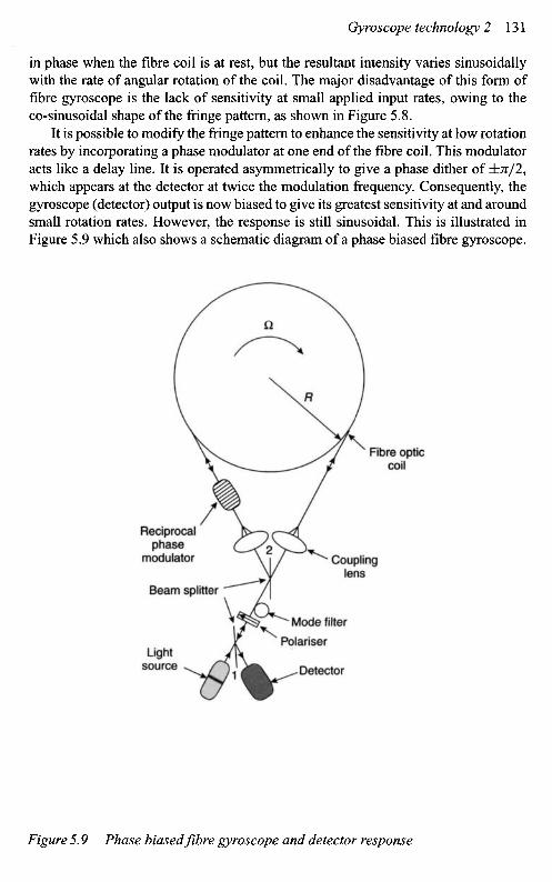
It is possible to modify the fringe pattern to enhance the sensitivity at low rotationrates by incorporating a phase modulator at one end of the fibre coil. This modulatoracts like a delay line. It is operated asymmetrically to give a phase dither of ±7t/2,which appears at the detector at twice the modulation frequency. Consequently, thegyroscope (detector) output is now biased to give its greatest sensitivity at and aroundsmall rotation rates. However, the response is still sinusoidal. This is illustrated inFigure 5.9 which also shows a schematic diagram of a phase biased fibre gyroscope.
Fibre opticcoil
Reciprocalphase
modulator
Beam splitter
Lightsource
Couplinglens
Mode filter
Detector
Stablezero
Output
Open loopbiased signal
Phasedifference
Figure 5.9 Phase biased fibre gyroscope and detector response
Polariser
The phase modulator can be made by winding a few turns of optical fibreround a piezoelectric cylinder. A square wave signal may be applied to this cylin-der to make it change shape and consequently to modulate the optical path length ofthe fibre coil.
Closed loop operationThere are many applications that require good accuracy over a wide angular rate range,possibly up to hundreds of degrees per second, and not merely at or close to 'zero rate'.It is generally desirable that the scale-factor linking the perceived angular motion tothe actual motion should have good stability, be linear and be independent of thereturning optical power. This can be achieved using a closed loop signal processingapproach. Two techniques, or architectures, have been demonstrated, namely phasenulling and frequency nulling.
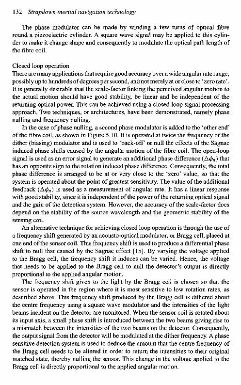
In the case of phase nulling, a second phase modulator is added to the 'other end'of the fibre coil, as shown in Figure 5.10. It is operated at twice the frequency of thedither (biasing) modulator and is used to 'back-off or null the effects of the Sagnacinduced phase shifts caused by the angular motion of the fibre coil. The open-loopsignal is used as an error signal to generate an additional phase difference (AcJ)n) thathas an opposite sign to the rotation induced phase difference. Consequently, the totalphase difference is arranged to be at or very close to the 'zero' value, so that thesystem is operated about the point of greatest sensitivity. The value of the additionalfeedback (AcJ)n) is used as a measurement of angular rate. It has a linear responsewith good stability, since it is independent of the power of the returning optical signaland the gain of the detection system. However, the accuracy of the scale-factor doesdepend on the stability of the source wavelength and the geometric stability of thesensing coil.
An alternative technique for achieving closed loop operation is through the use ofa frequency shift generated by an acousto-optical modulator, or Bragg cell, placed atone end of the sensor coil. This frequency shift is used to produce a differential phaseshift to null that caused by the Sagnac effect [15]. By varying the voltage appliedto the Bragg cell, the frequency shift it induces can be varied. Hence, the voltagethat needs to be applied to the Bragg cell to null the detector's output is directlyproportional to the applied angular motion.
The frequency shift given to the light by the Bragg cell is chosen so that thesensor is operated in the region where it is most sensitive to low rotation rates, asdescribed above. This frequency shift produced by the Bragg cell is dithered aboutthe centre frequency using a square wave modulator and the intensities of the lightbeams incident on the detector are monitored. When the sensor coil is rotated aboutits input axis, a small phase shift is introduced between the two beams giving rise toa mismatch between the intensities of the two beams on the detector. Consequently,the output signal from the detector will be modulated at the dither frequency. A phasesensitive detection system is used to deduce the amount that the centre frequency ofthe Bragg cell needs to be altered in order to return the intensities to their originalmatched state, thereby nulling the sensor. This change in the voltage applied to theBragg cell is directly proportional to the applied angular motion.
Figure 5.10 Closed loop (phase nulled) fibre gyroscope and detector response
The principal drawback of this architecture is the generation of a suitablebandwidth of frequencies in the modulator. This can be achieved by using two acousto-optical modulators at opposite ends of the sensor coil and dithering their frequenciesabout a centre frequency. An alternative approach is to use two modulators in oppo-sition at one end of the fibre coil. With both arrangements, great care is required toachieve satisfactory mechanical stability of the whole assembly.
One technique that is currently used is the so-called phase ramp, serrodyne mod-ulation [16], which relies on the fact that a frequency can be considered to be a timederivative of phase. In practice, a sawtooth waveform is used to modulate the appliedphase shift, with a very fast 'flyback' at the reset positions. An alternative method thatalleviates the 'flyback' problem is the digital phase ramp. In this case, 'phase steps'are generated with a duration equal to the group delay difference in time between
Fibre opticcoil
DithermodulatorPhase
nullingmodulator Coupling
lens
Beam splitter
Lightsource
Mode filter
Polariser
Detector
OutputStablezero
Open loopsignal Feedback
Phasedifference

the long and short paths that connect the phase modulator and the beam splitter.These 'phase steps' and the resets can be synchronised with a square-wave biasingmodulation. The use of digital logic enables this technique to be implemented easily.
One of the current developments of the fibre optic gyroscope is the demonstrationof the so-called integrated fibre optic gyroscope. In this device, all the bulk optical,or fibre, components are replaced with components fused into a lithium niobatesubstrate [16]; it is used to produce the beam splitter or couplers, optical wave-guides and the necessary modulation to the light required to measure the rotation rateaccurately. Fibre 'leads' are used to connect the source and detector to this so-calledintegrated optics 'chip'. This form of gyroscope has the potential to be compact,rugged and have a long shelf-life whilst retaining the advantages of optical sensorslisted earlier in Section 5.1. Currently these sensors are about 70-80 mm in diameter;a size which is a compromise between producing a compact sensor and avoidingexcessive biases induced by the strain in the fibre when bent into a small radius ofcurvature. Photographs of a commercially available fibre optic inertial measurementunit are shown in Figure 5.11.
As perceived, the use of a reciprocal path in optical sensors like the fibre opticgyroscope should be free from errors associated with the environment, such as tem-perature, acceleration and vibration. However, regrettably these devices do exhibitsome sensitivity to these effects. Fortunately, through careful design, particularly thewinding of the sensor coil, these sensitivities can be minimised. These effects areconsidered below.
5.1.5.4 Sources of error
Changes in ambient temperature can cause a bias or drift to be observed because of amultitude of effects within the sensor, temperature gradients within the sensor beinga particular problem. As the ambient temperature changes, the source wavelengthchanges and the sensitivity of the sensor is inversely proportional to the source wave-length. Temperature changes result in variation of the refractive index of the opticalfibre leading to changes in the modulation. If possible, the expansion coefficient ofthe fibre and the coil former should be well matched, or else differential stresses areinduced by thermal expansion which result in measurement errors. Thermal changesalso alter the size of the coil resulting in changes in the scale-factor of the gyroscope.
A bias occurs when there is a time-dependent thermal gradient along the opticalfibre as a result of a temperature gradient across the coil. This results in a non-reciprocity occurring when corresponding wave fronts of the counter-rotating beamscross the same region at different times. This is known as the Shupe effect [19].Anti-Shupe windings have been devised so that parts of the optical fibre that areequal distances from the centre of the coil are adjacent.
When an acceleration is applied to a coil, it can result in the distortion of the coilproducing a change in the scale-factor of the gyroscope. Distortions also change thebirefringence of the fibre and hence, the bias of the sensor. Additionally, distortionscan lead to changes in the direction of the sensitive axis and, in the case of a three-axisconfiguration, changes in the relative orientation or alignment of the three input axes.
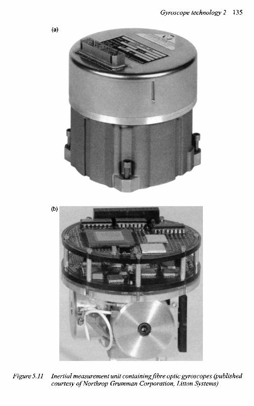
Figure 5.11 Inertial measurement unit containing fibre optic gyroscopes (publishedcourtesy of Northrop Grumman Corporation, Litton Systems)
Application of vibratory motion to a coil of fibre, or length of fibre, can lead to adistortion of the coil and the fibre, depending on the amplitude of the input motion.As discussed earlier, this leads to errors in the angular motion measurements madeby the sensor.
The presence of stray magnetic fields also can have an adverse effect owingto interaction with the non-optical components. Magnetic fields can also producechanges in the state of polarisation of the light in the optical fibre through the Faradayeffect. These sensitivities lead to a bias in the output signal from the device. The useof magnetic shielding can minimise this effect.
The bias and drift in the output signal is a consequence mainly of birefringence inthe optical fibre and propagation of cladding modes, as well as polarisation modulationof the optical signals. The problem is essentially one of many modes existing withinthe fibre, each with a different phase and with a lack of coherence, so fading occurs.One method of overcoming spurious coherent effects, including scattering within thefibre, is to use a low coherence source, i.e. one with a short coherence length. A super-luminescent diode fulfils this criterion. Use of this source also minimises the bias gen-erated by the Kerr electro-optic effect, caused by changes in the refractive index of theoptical medium through variations in the power of the two counter-propagating beams.
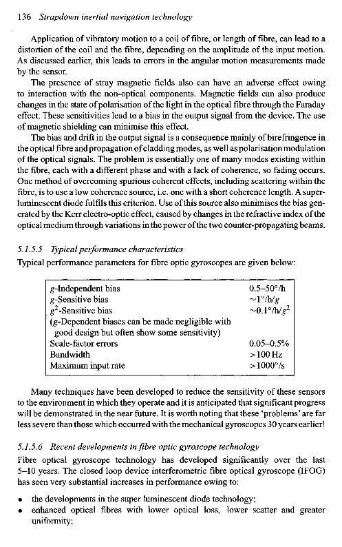
5.1.5.5 Typical performance characteristics
Typical performance parameters for fibre optic gyroscopes are given below:
g-Independent bias 0.5-50°/hg-Sensitive bias ~ 1 °/h/gg2-Sensitive bias ~0. l°/h/g2
(g-Dependent biases can be made negligible withgood design but often show some sensitivity)
Scale-factor errors 0.05-0.5%Bandwidth > 100 HzMaximum input rate > 1000°/s
Many techniques have been developed to reduce the sensitivity of these sensorsto the environment in which they operate and it is anticipated that significant progresswill be demonstrated in the near future. It is worth noting that these 'problems' are farless severe than those which occurred with the mechanical gyroscopes 30 years earlier!
5.7.5.6 Recent developments in fibre optic gyroscope technology
Fibre optical gyroscope technology has developed significantly over the last5-10 years. The closed loop device interferometric fibre optical gyroscope (IFOG)has seen very substantial increases in performance owing to:
• the developments in the super luminescent diode technology;• enhanced optical fibres with lower optical loss, lower scatter and greater
uniformity;

• the perfection of the functions of the integrated circuit chip, such as the polarisa-tion of the light, the splitting of the beam into the clockwise and counter-clockwisebeams, the recombination and control of the frequency shifting process;
• the development of microprocessor technology that can be combined withinthe sensor to give real-time accurate compensation of systematic errors.
Modern technology enables each sensor to be calibrated and appropriate com-pensation techniques applied, particularly for the effects of changes in temperature.Moreover, it allows the same architecture to be used in different performance sen-sors, by reducing the length of optical fibre needed for the lower performance devices.However, the modulation frequency still has to be tracked to the actual length of fibreto give the optimum performance for the chosen fibre length.
The measurement accuracy of these IFOGs is now approaching, if not com-parable with, that of a standard inertial-quality ring laser gyroscope. The IFOGdevices have yet to supersede the ring laser gyroscope in the high performanceapplications owing to the industrial investment in this technology base. However,as the cost of the IFOG technology decreases they are very likely to replace ringlaser gyroscopes. A high-performance IFOG can have the following performancecharacteristics.
Parameter Value
Bias stability <0.0003°/hRandom walk <0.00008°/v/hScale-factor error <0.5ppm
IFOG technology has been used in many lower-grade applications. Examplesinclude: unmanned air vehicles, unmanned underwater vehicles, many types ofstabilisation, gyrocompasses, and attitude and heading reference systems.
The major thrust is cost and size reduction. Atypical example is the development ofa fibre optical gyroscope triad system, a system being produced by the Litef companyin Germany. In this system the cost of the super luminescent diode was identified asa major cost driver in any FOG-based system. The solution was to use a single super-luminescent diode and share the light with the three fibre coils via their integratedoptical chips. This class of optical device is reported to have a bias stability in the0.05°/h class. Changes to the coil design enables lower-grade performance to beachieved, but still maintaining a very high-quality linear scale-factor. A schematic ofthis arrangement is shown in Figure 5.12.
5.1.6 Photonic crystal optical fibre gyroscope
New optical fibre technology [20] is being developed that gives superior light-guidingproperties compared with traditional step-index fibres. These new optical fibres havea periodic array of holes in the structure that provide very high-quality light-guiding

(b)
I/O Processor PROM Power
:^m^
Figure 5.12 (a) Fibre optical gyroscope triad structure, (b) Sensor block (publishedcourtesy of Lite/GmbH)
Depolariser PMF SMF
1:3-SM-Coupler
Fibre splices
2:2-SM-Coupler PMF:Optical filter
ASIC
PMF
Temp, sensors
mmm •Hi

properties with very low optical losses. In fact they are sometimes known as holeyfibres and come in two forms depending on the construction of the core:
• photonic crystal fibres have a solid core, to transmit the light, that is surrounded byan array of holes that give a reduced refractive index to the surrounding medium;
• photonic band gap devices with a void or defect in the centre of the core for thetransmission of light, so the light passes along a hollow core. The array of holescreates a band gap analogue to a semiconductor allowing the light to propagatein only certain parts of the structure, trapping it in others.
These classes of fibre provide very tight mode confinement of the propagatinglight, and single mode propagation is possible over many wavelengths. Additionally,the polarisation maintaining versions of these fibres have demonstrated ten timesthe birefringence of the conventional fibres.
The tight mode confinement results in much smaller bend losses so tighter coilscan be produced leading to much smaller packages. Additionally, the smaller claddingstructure also allows small devices to be made without impeding performance.
It is possible to embody dispersion compensation into these fibres to reduce theeffects of spectral distortion of the propagating light on the performance of the sensor.Additionally, the micro-structured fibres could be used with light having a wavelengthin the 1-2 |xm waveband.
Figure 5.13 shows two types of micro-structured optical fibre.
Photonic band gap fibre
Photonic crystal fibre
Figure 5.13 Micro-structured fibres
Frequencyshifter
(b)Intensity
at the detector
99:1 Fibre coupler
Key:— Sensor stationary
Second resonancefrom rotation
Sagnacfrequency
split
Frequency
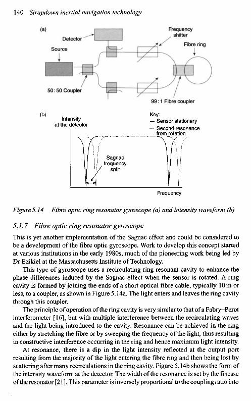
Figure 5.14 Fibre optic ring resonator gyroscope (a) and intensity waveform (b)
5.1.7 Fibre optic ring resonator gyroscope
This is yet another implementation of the Sagnac effect and could be considered tobe a development of the fibre optic gyroscope. Work to develop this concept startedat various institutions in the early 1980s, much of the pioneering work being led byDr Ezikiel at the Massachusetts Institute of Technology.
This type of gyroscope uses a recirculating ring resonant cavity to enhance thephase differences induced by the Sagnac effect when the sensor is rotated. A ringcavity is formed by joining the ends of a short optical fibre cable, typically 10 m orless, to a coupler, as shown in Figure 5.14a. The light enters and leaves the ring cavitythrough this coupler.
The principle of operation of the ring cavity is very similar to that of a Fabry-Perotinterferometer [16], but with multiple interference between the recirculating wavesand the light being introduced to the cavity. Resonance can be achieved in the ringeither by stretching the fibre or by sweeping the frequency of the light, thus resultingin constructive interference occurring in the ring and hence maximum light intensity.
At resonance, there is a dip in the light intensity reflected at the output portresulting from the majority of the light entering the fibre ring and then being lost byscattering after many recirculations in the ring cavity. Figure 5.14b shows the form ofthe intensity waveform at the detector. The width of the resonance is set by the finesseof the resonator [21]. This parameter is inversely proportional to the coupling ratio into
Detector
Source
50:50 Coupler
Fibre ring

the ring. Hence, it is necessary to have a high coupling ratio. The quality of the cavity,and its sensitivity, is defined by the finesse, which is the ratio of the free spectral rangeto the linewidth of the resonance. The resonant condition is observed by detectingthe energy reflected by the coupler linking the fibre ring to the source and detector.
When the sensor is stationary, the resonant frequencies of the two counter-propagating beams are identical. When the ring is rotated about its sensitive axis,the resonant frequencies of the two counter-propagating beams differ. This results ina shift in the positions of the resonances and hence, in the light intensity from theoutput port.
Equation (5.19), derived earlier, for the fibre optic gyroscope gives thephase difference for the two beams. Because the two counter-propagating beamsexperience different loop paths, there is a different resonance frequency (vd) gener-ated in each direction. It is given in terms of the radius of the coil by substitution forA (=7iR2) and L (=2TTR) in eqn. (5.11). Hence:
M - ^ (MOA
where R is the radius of the coil, Q1 is the applied rate and k is the wavelength.Clearly, the number of turns of fibre does not influence its sensitivity, as this is
dependent on the radius of the loop for a given wavelength and rotation rate. Hence,given practical considerations, the length of optical fibre required is very much less,typically of the order of 10 m.
This sensor is used in a feedback mode so the frequency of the two counter-propagating beams is shifted when the sensor is rotated, thus keeping the twobeams at resonance simultaneously even under rotation. Sinusoidal phase modulationwith frequency modulation can be applied to the two counter-propagating beams.The difference between the two modulations required to maintain resonance in thetwo beams is proportional to the applied rotation rate.
The fundamental requirement for the light energy used in this sensor is that it hasa narrow bandwidth and a high coherence. Hence, a light source is needed that isvery stable in order to maintain the narrow width resonance in the ring. Currently, thelasers that fulfil this requirement are expensive, but with the development of quantumwell lasers the price should reduce. Careful design is required to avoid incoherentback-scattering from one beam to the other and the consequent onset of the familiar'lock-in' problem. It is usual to control the polarisation of the light before it entersthe ring to avoid intensity fading.
As in the case of the fibre optic gyroscope, the bulk optical components can bereplaced with integrated optical materials using guided waves. Hence this, togetherwith the very short length of fibre, typically 10 m or less, can lead to a very compactsensor.
Currently, this sensor is being developed by a number of companies but definiteperformance and error data are not available. However, it is expected to have a similarperformance to the fibre gyroscope; data for that sensor are given in Section 5.1.5.5.Generally, it is considered to be more sensitive than the fibre gyroscope, possiblyby a factor of 3 [22].
5.1.7.1 Ring resonator rotation rate sensors - non-linear modeCurrently the measurement of rotation rate by the exploitation of non-linear effects,induced in the energy in the ring resonator, has been investigated. These non-lineareffects occur when there is only a small loss, of the order of 5 percent, in the ring,leading to about a 20-fold increase in power. The non-linear interactions are usuallydivided into two groups, intensity dependent refractive index effects and scatteringphenomena. In the case of the fibre optic gyroscope, these non-linear effects areconsidered detrimental as they degrade performance.
The non-linear refractive index effect makes use of the Kerr effect [8]. The electricfield of the optical energy propagating through a medium produces a refractive indexchange. Now, when a ring resonator, operating in a resonant condition, is rotated,the intensity in one direction decreases whilst the intensity in the other directiondecreases. Additionally, the refractive index in each direction also changes, ampli-fying the intensity change. This amplification can be varied by changing both theparameters of the resonant ring and the Kerr material, which, in turn, improves thesensitivity of the resonator.
The propagation of a high power optical beam through a dense medium producesphonons; energy is transferred to these phonons resulting in a change in frequencyof the beam. This results in a scattered optical wave with a modified frequency. Thetwo major types of non-linear scattering are called Brillouin and Raman [23], andare threshold effects; Brillouin occurs at lower power levels. Brillouin scattering hasa characteristic linewidth which requires a source with a coherence length shorterthan the life time of a phonon. Consequently, a coherent source produces Brillouinscattering in preference to Raman.
It has been suggested [24] that a ring laser, exhibiting Brillouin scattering, pumpedfrom both directions will produce a frequency difference between Brillouin scatteredenergy that is directly proportional to the rotation rate. This sensor should producea signal that is similar to that produced by a ring laser gyroscope, that is, a rotationrate dependent frequency. However, there should not be any lock-in as the two scattermechanisms should be independent.
A sensor has also been proposed based on the Raman scatter phenomena usinghigh power pulses from a mode locked laser [25]. It appears that the major drawbackwill be the size of the sensor. Currently, there are no reports indicating that any ofthese sensors have been demonstrated.
5.1.8 Ring resonator gyroscope
This sensor is very similar to the fibre optic ring resonator, but the fibre ring isreplaced with an optical waveguide which can be etched into a suitable substrate [26].The principle of operation is very similar to that described for the fibre optic ringresonator. Typical rings are about 50 mm in diameter. Hence, when the problemsassociated with scattering and coupling can be overcome, the prospect of a gyroscopeon a 'chip' can become a reality, along with all the advantages of optical sensors.
This type of sensor has been developed by Northrop in the United States[7] and is known as the micro-optic gyroscope (MOG). Rugged sensors with a
diameter of about 25 mm have been produced with performance in the l-100°/hcategory.
5.1.9 Integrated optical gyroscope
There have been developments in this highly desirable sensor, as it is a 'gyroscopeon a chip'. The sensing element is an optical waveguide on a substrate with the lighttravelling in opposite directions. The relative position of the resonance within thering is a measure of the applied optical rotation rate about an axis that is perpendic-ular to the ring. The fundamental operation of this device is described more fully inSection 5.1.7.
These integrated optical gyroscopes are created on wafers and combine micro-machined electromechanical system processes and integrated optical fabricationprocesses. Speciality glasses are formed by highly specialised techniques such asflame hydrolysed deposition, radio frequency and reactive sputtering. The flamehydrolysed deposition allows the refractive index of the medium to be controlled sothat the glass can be doped with rare earth laser ions, such as neodymium, ytterbiumor erbium, creating lasers and laser amplifiers within the chip.
The definition of the waveguide is still quite a challenge, as vertical sidewallswith very low roughness are required to minimise losses. Clearly, the etching processis potentially the limiting process in the fabrication as there are likely to be variouscompositions of glass with varying dopant concentrations.
Currently, the performance goal is to meet applications requiring perfor-mance in the 0.1-l°/h regime. This class of sensor offers significant size and massreduction, of the order of a factor of 20 compared with conventional fibre gyroscopes.Additionally, the power consumption is likely to be reduced by a factor of 5 or 6 alongwith a significantly lower cost owing to the reduced number of optical components.
5.2 Cold atom sensors
5.2.1 Introduction
This is an approach or technique for measuring inertial properties; such devicesare also known as atom interferometer devices and owe much to the excellentwork of Professor Chu of Stanford University. The technique is in the early stagesof practical development and offers the prospect of a route to the most accurateaccelerometers, gyroscopes, precision clocks and gravity gradiometers therefore per-formance enhancements of several orders of magnitude are predicted. If successfuldevices can be devised then, given precise knowledge of the gravity field, there isthe prospect of a sub lOm/h navigation capability without using global positioningsystem (GPS) or other external aiding techniques.
The sensor relies on the super cooling of an atom or molecule by techniquessuch as laser cooling and uses the de Broglie wavelength of an atom, which is about3 x 104 smaller than the wavelength of visible light. The physical principle relies on
Next Page