Embed Size (px)
Citation preview

H O T R U N N E R T E C H N O L O G Y
G24 Temperature Controller
2
Prec
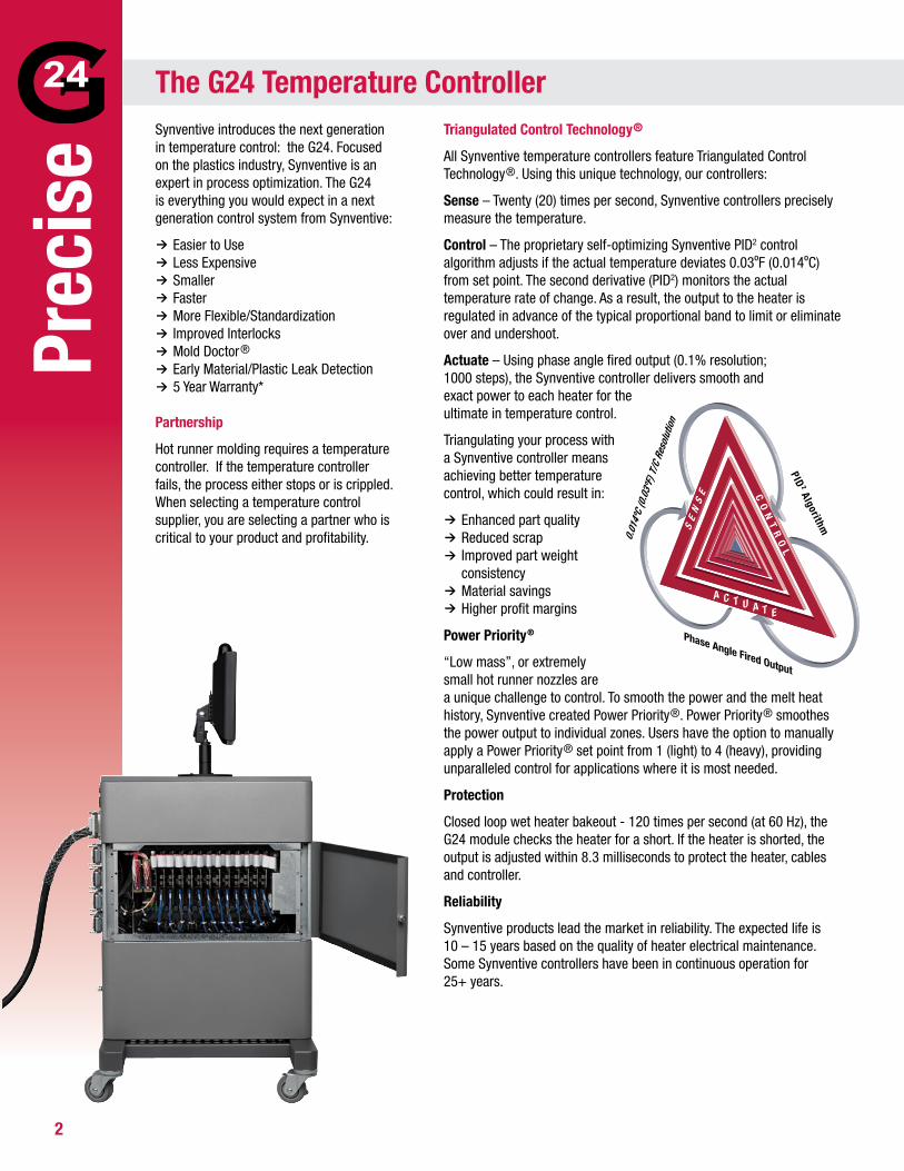
ise Synventive introduces the next generation
in temperature control: the G24. Focused on the plastics industry, Synventive is an expert in process optimization. The G24 is everything you would expect in a next generation control system from Synventive:
Easier to Use Less Expensive Smaller Faster More Flexible/Standardization Improved Interlocks Mold Doctor® Early Material/Plastic Leak Detection 5 Year Warranty*
Partnership
Hot runner molding requires a temperature controller. If the temperature controller fails, the process either stops or is crippled. When selecting a temperature control supplier, you are selecting a partner who is critical to your product and profitability.
Triangulated Control Technology®
All Synventive temperature controllers feature Triangulated Control Technology®. Using this unique technology, our controllers:
Sense – Twenty (20) times per second, Synventive controllers precisely measure the temperature.
Control – The proprietary self-optimizing Synventive PID2 control algorithm adjusts if the actual temperature deviates 0.03ºF (0.014ºC) from set point. The second derivative (PID2) monitors the actual temperature rate of change. As a result, the output to the heater is regulated in advance of the typical proportional band to limit or eliminate over and undershoot.
Actuate – Using phase angle fired output (0.1% resolution; 1000 steps), the Synventive controller delivers smooth and exact power to each heater for the ultimate in temperature control.
Triangulating your process with a Synventive controller means achieving better temperature control, which could result in:
Enhanced part quality Reduced scrap Improved part weight consistency Material savings Higher profit margins
Power Priority®
“Low mass”, or extremely small hot runner nozzles are a unique challenge to control. To smooth the power and the melt heat history, Synventive created Power Priority®. Power Priority® smoothes the power output to individual zones. Users have the option to manually apply a Power Priority® set point from 1 (light) to 4 (heavy), providing unparalleled control for applications where it is most needed.
Protection
Closed loop wet heater bakeout - 120 times per second (at 60 Hz), the G24 module checks the heater for a short. If the heater is shorted, the output is adjusted within 8.3 milliseconds to protect the heater, cables and controller.
Reliability
Synventive products lead the market in reliability. The expected life is 10 – 15 years based on the quality of heater electrical maintenance. Some Synventive controllers have been in continuous operation for 25+ years.
The G24 Temperature Controller
CO
NT
RO
L
Phase Angle Fired Output
A C T U A T E
PID2 AlgorithmS
EN
SE
3
Easier to Use
Best industry practices and actual operation are often not the same. The G24 is designed to be understood with 5 minutes of training, and programmable to automatically operate according to the industry’s best practices. An optional Sequence Start can be activated to only power the manifold/sprue zones, wait until they reach temperature, start a soak period countdown timer and finally heat the smaller, faster heating nozzle zones. This practice is always recommended but seldom done in the industry. The primary benefits include maintaining the integrity of the manifold seal by controlling heat expansion and preventing material degradation caused by excessive nozzle heater material residence time.
Less Expensive
By leveraging the global electronics supply chain with new components that take the place of multiple previous components, Synventive has been able to reduce the price of the G24 product line in relation to existing Synventive products. Synventive, long known as the reliability and control leader in the industry, combines a competitive price with superior performance in the G24 controller.
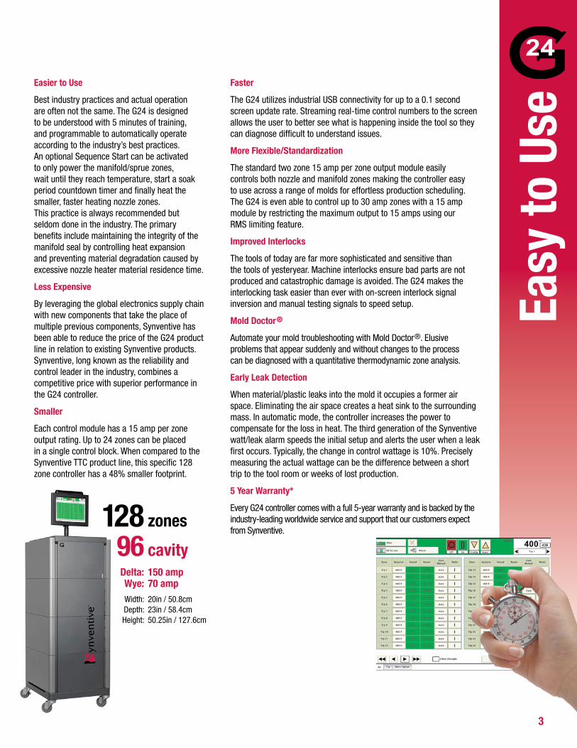
Smaller
Each control module has a 15 amp per zone output rating. Up to 24 zones can be placed in a single control block. When compared to the Synventive TTC product line, this specific 128 zone controller has a 48% smaller footprint.
Faster
The G24 utilizes industrial USB connectivity for up to a 0.1 second screen update rate. Streaming real-time control numbers to the screen allows the user to better see what is happening inside the tool so they can diagnose difficult to understand issues.
More Flexible/Standardization
The standard two zone 15 amp per zone output module easily controls both nozzle and manifold zones making the controller easy to use across a range of molds for effortless production scheduling. The G24 is even able to control up to 30 amp zones with a 15 amp module by restricting the maximum output to 15 amps using our RMS limiting feature.
Improved Interlocks
The tools of today are far more sophisticated and sensitive than the tools of yesteryear. Machine interlocks ensure bad parts are not produced and catastrophic damage is avoided. The G24 makes the interlocking task easier than ever with on-screen interlock signal inversion and manual testing signals to speed setup.
Mold Doctor®
Automate your mold troubleshooting with Mold Doctor®. Elusive problems that appear suddenly and without changes to the process can be diagnosed with a quantitative thermodynamic zone analysis.
Early Leak Detection
When material/plastic leaks into the mold it occupies a former air space. Eliminating the air space creates a heat sink to the surrounding mass. In automatic mode, the controller increases the power to compensate for the loss in heat. The third generation of the Synventive watt/leak alarm speeds the initial setup and alerts the user when a leak first occurs. Typically, the change in control wattage is 10%. Precisely measuring the actual wattage can be the difference between a short trip to the tool room or weeks of lost production.
5 Year Warranty*
Every G24 controller comes with a full 5-year warranty and is backed by the industry-leading worldwide service and support that our customers expect from Synventive.
Easy
to U
se 128 zones
96 cavity Delta: 150 amp Wye: 70 amp Width: 20in / 50.8cm Depth: 23in / 58.4cm Height: 50.25in / 127.6cm
4
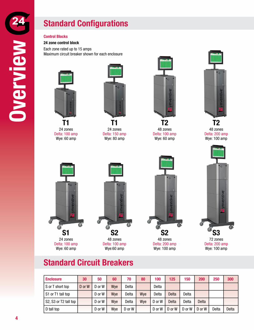
Control Blocks24 zone control blockEach zone rated up to 15 amps Maximum circuit breaker shown for each enclosure
T124 zones
Delta: 100 ampWye: 60 amp
S372 zones
Delta: 200 ampWye: 100 amp
S124 zones
Delta: 100 ampWye: 60 amp
S248 zones
Delta: 100 ampWye:60 amp
S248 zones
Delta: 200 ampWye: 100 amp
T124 zones
Delta: 150 ampWye: 80 amp
T248 zones
Delta: 100 ampWye: 60 amp
T248 zones
Delta: 200 ampWye: 100 amp
Over
view
Standard Configurations
Standard Circuit Breakers
Enclosure 30 50 60 70 80 100 125 150 200 250 300
S or T short top D or W D or W Wye Delta Delta
S1 or T1 tall top D or W Wye Delta Wye Delta Delta Delta
S2, S3 or T2 tall top D or W Wye Delta Wye D or W Delta Delta Delta
D tall top D or W Wye D or W D or W D or W D or W D or W Delta Delta
5
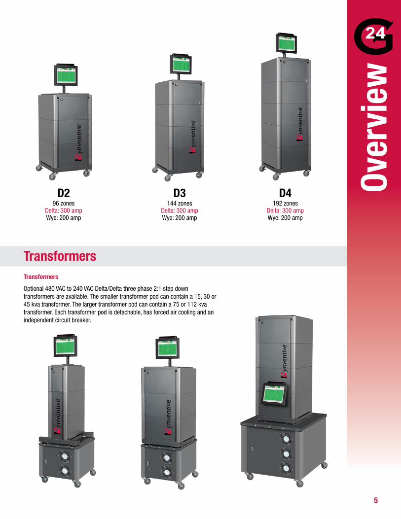
Transformers
Optional 480 VAC to 240 VAC Delta/Delta three phase 2:1 step down transformers are available. The smaller transformer pod can contain a 15, 30 or 45 kva transformer. The larger transformer pod can contain a 75 or 112 kva transformer. Each transformer pod is detachable, has forced air cooling and an independent circuit breaker.
D296 zones
Delta: 300 ampWye: 200 amp
D3144 zones
Delta: 300 ampWye: 200 amp
D4192 zones
Delta: 300 ampWye: 200 amp
Over
view
Transformers
6
(-)(+)123456789101112
123456789101112
131415161718192021222324
131415161718192021222324
Zone 1Zone 2Zone 3Zone 4Zone 5Zone 6Zone 7Zone 8Zone 9Zone 10Zone 11Zone 12
123456789
123456789
123456789
123456789
Zone 1Zone 5Zone 2
Zone 3Zone 7
Zone 6
Zone 4
Zone 8
Zone 9
Zone 10
Zone 11Zone 12
Zone 8
Zone 9
Zone 10
Zone 11Zone 12
(-)(+)123456789101112
252627282930313233343536
131415161718192021222324
373839404142434445464748
Zone 1Zone 2Zone 3Zone 4Zone 5Zone 6Zone 7Zone 8Zone 9Zone 10Zone 11Zone 12
(+)(-)
123456789101112
131415161718192021222324
Z1 PwrZ2 PwrZ3 PwrZ4 PwrZ5 PwrZ6 PwrZ1 T/CZ2 T/CZ3 T/CZ4 T/CZ5 T/CZ6 T/C
123456789101112
131415161718192021222324
Z1 Pwr
Z2 Pwr
Z3 Pwr
Z4 Pwr
Z5 Pwr
Z6 Pwr
Z1 T/C
Z2 T/C
Z3 T/C
Z4 T/C
Z5 T/C
Z6 T/C
(+)(-)
123456789101112
131415161718192021222324
Z7 PwrZ8 PwrZ9 PwrZ10 PwrZ11 PwrZ12 PwrZ7 T/CZ8 T/CZ9 T/CZ10 T/CZ11 T/CZ12 T/C
123456789101112
131415161718192021222324
Z7 Pwr
Z8 Pwr
Z9 Pwr
Z10 Pwr
Z11 Pwr
Z12 Pwr
Z7 T/C
Z8 T/C
Z9 T/C
Z10 T/C
Z11 T/C
Z12 T/C
ThermocouplePower
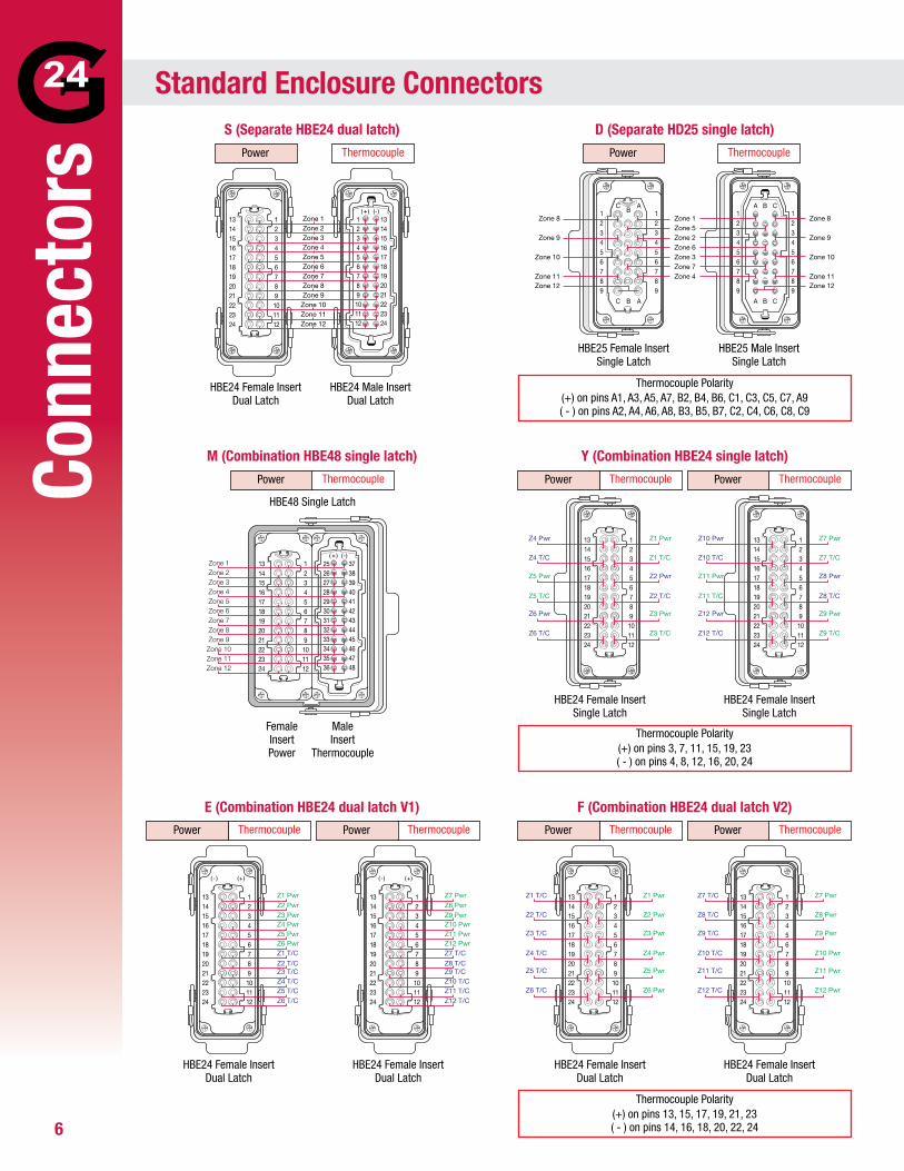
S (Separate HBE24 dual latch)
M (Combination HBE48 single latch)
E (Combination HBE24 dual latch V1)
D (Separate HD25 single latch)
Y (Combination HBE24 single latch)
F (Combination HBE24 dual latch V2)
Thermocouple ThermocouplePower Power
HBE24 Female Insert Dual Latch
Female Insert Power
123456789101112
131415161718192021222324
Z1 Pwr
Z1 T/C
Z2 Pwr
Z2 T/C
Z3 Pwr
Z3 T/C
Z4 Pwr
Z4 T/C
Z5 Pwr
Z5 T/C
Z6 Pwr
Z6 T/C
ThermocouplePower
ThermocouplePower ThermocouplePower
HBE24 Female Insert Single Latch
123456789101112
131415161718192021222324
Z7 Pwr
Z7 T/C
Z8 Pwr
Z8 T/C
Z9 Pwr
Z9 T/C
Z10 Pwr
Z10 T/C
Z11 Pwr
Z11 T/C
Z12 Pwr
Z12 T/C
ThermocouplePower
ThermocouplePower ThermocouplePower
HBE24 Female Insert Single Latch
HBE25 Female Insert Single Latch
HBE24 Female Insert Dual Latch
HBE24 Female Insert Dual Latch
Thermocouple Polarity(+) on pins A1, A3, A5, A7, B2, B4, B6, C1, C3, C5, C7, A9 ( - ) on pins A2, A4, A6, A8, B3, B5, B7, C2, C4, C6, C8, C9
Thermocouple Polarity(+) on pins 3, 7, 11, 15, 19, 23( - ) on pins 4, 8, 12, 16, 20, 24
Thermocouple Polarity(+) on pins 13, 15, 17, 19, 21, 23( - ) on pins 14, 16, 18, 20, 22, 24
HBE24 Male Insert Dual Latch
HBE48 Single Latch
Male Insert
Thermocouple
HBE25 Male Insert Single Latch
HBE24 Female Insert Dual Latch
HBE24 Female Insert Dual Latch
Conn
ecto
rsStandard Enclosure Connectors
7
(-)(+)252627282930313233343536
373839404142434445464748
(-)(+)252627282930313233343536
373839404142434445464748
123456789101112
131415161718192021222324
123456789101112
131415161718192021222324
Zone 13Zone 14Zone 15Zone 16Zone 17Zone 18Zone 19Zone 20Zone 21Zone 22Zone 23Zone 24
Zone 13Zone 14Zone 15Zone 16Zone 17Zone 18Zone 19Zone 20Zone 21Zone 22Zone 23Zone 24
Zone 1Zone 2Zone 3Zone 4Zone 5Zone 6Zone 7Zone 8Zone 9Zone 10Zone 11Zone 12
Zone 1Zone 2Zone 3Zone 4Zone 5Zone 6Zone 7Zone 8Zone 9Zone 10Zone 11Zone 12
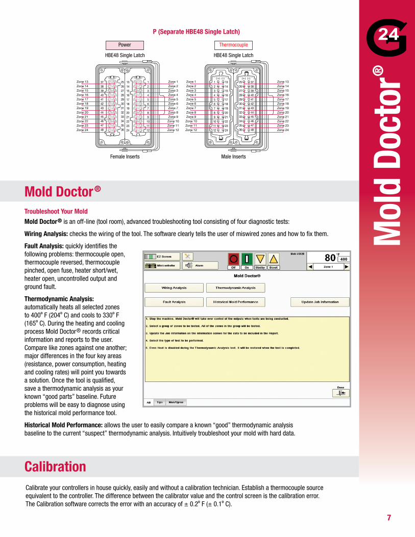
P (Separate HBE48 Single Latch)
ThermocouplePower
HBE48 Single Latch
Female Inserts
HBE48 Single Latch
Male Inserts
Troubleshoot Your MoldMold Doctor® is an off-line (tool room), advanced troubleshooting tool consisting of four diagnostic tests:
Wiring Analysis: checks the wiring of the tool. The software clearly tells the user of miswired zones and how to fix them.
Fault Analysis: quickly identifies the following problems: thermocouple open, thermocouple reversed, thermocouple pinched, open fuse, heater short/wet, heater open, uncontrolled output and ground fault.
Thermodynamic Analysis: automatically heats all selected zones to 400º F (204º C) and cools to 330º F (165º C). During the heating and cooling process Mold Doctor® records critical information and reports to the user. Compare like zones against one another; major differences in the four key areas (resistance, power consumption, heating and cooling rates) will point you towards a solution. Once the tool is qualified, save a thermodynamic analysis as your known “good parts” baseline. Future problems will be easy to diagnose using the historical mold performance tool.
Historical Mold Performance: allows the user to easily compare a known “good” thermodynamic analysis baseline to the current “suspect” thermodynamic analysis. Intuitively troubleshoot your mold with hard data.
Calibrate your controllers in house quickly, easily and without a calibration technician. Establish a thermocouple source equivalent to the controller. The difference between the calibrator value and the control screen is the calibration error. The Calibration software corrects the error with an accuracy of ± 0.2º F (± 0.1º C).
Mol
d Do
ctor
®
Mold Doctor®
Calibration
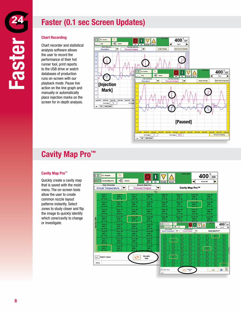
Chart Recording
Chart recorder and statistical analysis software allows the user to record the performance of their hot runner tool, print reports to the USB drive or watch databases of production runs on-screen with our playback mode. Pause live action on the line graph and manually or automatically place injection marks on the screen for in-depth analysis.
Cavity Map Pro™
Quickly create a cavity map that is saved with the mold menu. The on-screen tools allow the user to create common nozzle layout patterns instantly. Select zones to study closer and flip the image to quickly identify which zone/cavity to change or investigate.
Fast
erFaster (0.1 sec Screen Updates)
Cavity Map Pro™
[Injection Mark]
[Paused]
8
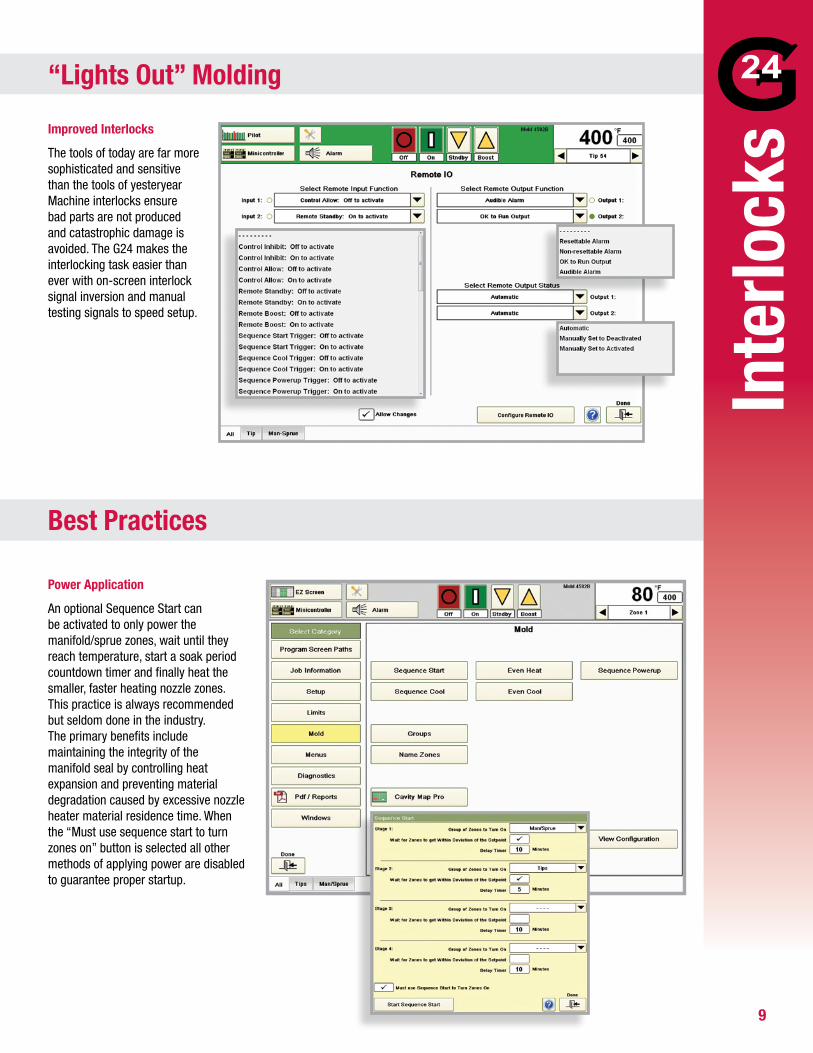
Improved Interlocks
The tools of today are far more sophisticated and sensitive than the tools of yesteryear Machine interlocks ensure bad parts are not produced and catastrophic damage is avoided. The G24 makes the interlocking task easier than ever with on-screen interlock signal inversion and manual testing signals to speed setup.
Power Application
An optional Sequence Start can be activated to only power the manifold/sprue zones, wait until they reach temperature, start a soak period countdown timer and finally heat the smaller, faster heating nozzle zones. This practice is always recommended but seldom done in the industry. The primary benefits include maintaining the integrity of the manifold seal by controlling heat expansion and preventing material degradation caused by excessive nozzle heater material residence time. When the “Must use sequence start to turn zones on” button is selected all other methods of applying power are disabled to guarantee proper startup.
“Lights Out” Molding
Best Practices
Inte
rlock
s
9
10
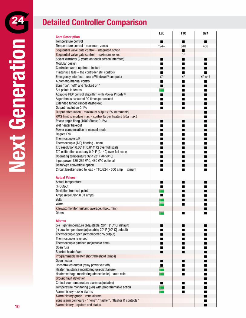
LEC TTC G24 Core DescriptionTemperature control Q� Q� QTemperature control - maximum zones *24+ 640 480Sequential valve gate control - integrated option QSequential valve gate control - maximum zones 325 year warranty (2 years on touch screen interface) Q� Q� QModular design Q� Q� QController warm up time - instant Q� Q� QIf interface fails – the controller still controls Q� Q� QEmergency interface - use a Windows® computer XP XP� XP or 7Automatic/manual control Q� Q� QZone “on”, “off” and “locked off” Q� Q� QSet points in tenths Q� QAdaptive PID2 control algorithm with Power Priority® Q� Q� QAlgorithm is executed 20 times per second Q� Q� QExtended tuning ranges (fast/slow) Q� Q� QOutput resolution 0.1% Q� Q� QOutput attenuation - maximum output (1% increments) QRMS limit to module max. - control larger heaters (30a max.) QPhase angle firing (1000 Steps; 0.1%) Q� Q� QWet heater bakeout Q� Q� QPower compensation in manual mode Q� Q� QDegree F/C Q� Q� QThermocouple J/K Q� Q� QThermocouple (T/C) filtering - none Q� Q� QT/C resolution 0.03o F (0.014o C) over full scale Q� Q� QT/C calibration accuracy 0.2o F (0.1o C) over full scale Q� Q� QOperating temperature 32-122o F (0-50o C) Q� Q� QInput power 180-265 VAC; 480 VAC optional Q� Q� QDelta/wye convertible option Q� Q� QCircuit breaker sized to load - TTC/G24 - 300 amp ximum Q� Q� Q
Actual ValuesActual temperature Q� Q� Q% Output Q� Q� QDeviation from set point Q� QAmps (resolution 0.01 amps) Q� Q� QVolts Q� QWatts Q� QKilowatt monitor (instant, average, max., min.) QOhms Q� Q
Alarms(+) High temperature (adjustable; 20º F [10º C] default) Q� Q� Q(-) Low temperature (adjustable; 20º F [10º C] default) Q� Q� QThermocouple open (remembered % output) Q� Q� QThermocouple reversed Q� Q� QThermocouple pinched (adjustable time) Q� Q� QOpen fuse Q� Q� QShorted heater/wet Q� Q� QProgrammable heater short threshold (amps) � � QOpen heater Q� Q� QUncontrolled output (relay power cut off) Q� Q� QHeater resistance monitoring (predict failure) Q� QHeater wattage monitoring (detect leaks) - auto calc. Q� QGround fault detection � � QCritical over temperature alarm (adjustable) Q� Q� Q Temperature monitoring (J/K) with programmable action Q� QAlarm history - zone alarms Q� QAlarm history graph - zone alarms QZone alarm configure - “none”, “flasher”, “flasher & contacts” QAlarm history - system and status � � Q
Next
Gen
erat
ion
Detailed Controller Comparison
11
Next
Gen
erat
ion
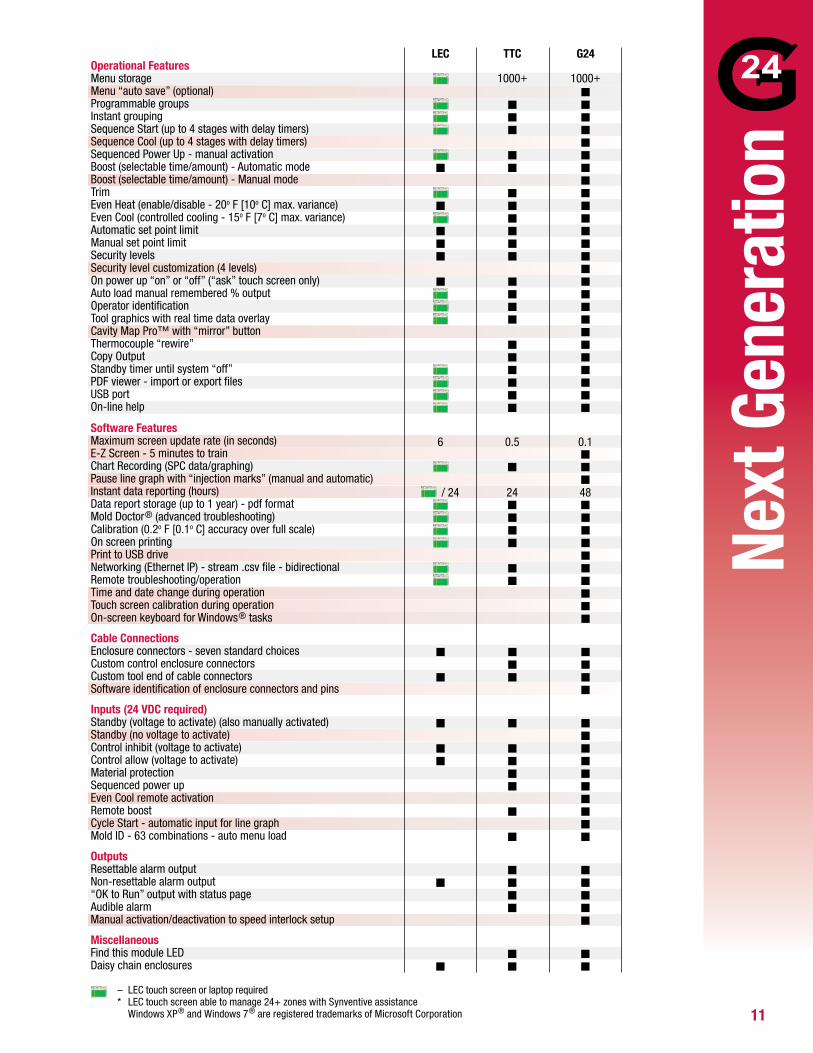
LEC TTC G24 Operational FeaturesMenu storage 1000+ 1000+Menu “auto save” (optional) QProgrammable groups Q� QInstant grouping Q� QSequence Start (up to 4 stages with delay timers) Q� QSequence Cool (up to 4 stages with delay timers) QSequenced Power Up - manual activation Q� QBoost (selectable time/amount) - Automatic mode Q� Q� QBoost (selectable time/amount) - Manual mode QTrim Q� QEven Heat (enable/disable - 20o F [10o C] max. variance) Q� Q� QEven Cool (controlled cooling - 15o F [7o C] max. variance) Q� QAutomatic set point limit Q� Q� QManual set point limit Q� Q� QSecurity levels Q� Q� QSecurity level customization (4 levels) QOn power up “on” or “off” (“ask” touch screen only) Q� Q� QAuto load manual remembered % output Q� QOperator identification Q� QTool graphics with real time data overlay Q� QCavity Map Pro™ with “mirror” button QThermocouple “rewire” Q� QCopy Output Q� QStandby timer until system “off” Q� QPDF viewer - import or export files Q� QUSB port Q� QOn-line help Q� Q
Software FeaturesMaximum screen update rate (in seconds) 6 0.5 0.1E-Z Screen - 5 minutes to train QChart Recording (SPC data/graphing) Q� QPause line graph with “injection marks” (manual and automatic) QInstant data reporting (hours) / 24 24 48Data report storage (up to 1 year) - pdf format Q� QMold Doctor® (advanced troubleshooting) Q� QCalibration (0.2o F [0.1o C] accuracy over full scale) Q� QOn screen printing Q� QPrint to USB drive QNetworking (Ethernet IP) - stream .csv file - bidirectional Q� QRemote troubleshooting/operation Q� QTime and date change during operation QTouch screen calibration during operation QOn-screen keyboard for Windows® tasks Q
Cable ConnectionsEnclosure connectors - seven standard choices Q� Q� QCustom control enclosure connectors Q� QCustom tool end of cable connectors Q� Q� QSoftware identification of enclosure connectors and pins Q
Inputs (24 VDC required)Standby (voltage to activate) (also manually activated) Q� Q� QStandby (no voltage to activate) QControl inhibit (voltage to activate) Q� Q� QControl allow (voltage to activate) Q� Q� QMaterial protection Q� QSequenced power up Q� QEven Cool remote activation QRemote boost Q� QCycle Start - automatic input for line graph QMold ID - 63 combinations - auto menu load Q� Q
OutputsResettable alarm output Q� QNon-resettable alarm output Q� Q� Q“OK to Run” output with status page Q� QAudible alarm Q� QManual activation/deactivation to speed interlock setup Q
MiscellaneousFind this module LED Q� QDaisy chain enclosures Q� Q� Q
– LEC touch screen or laptop required * LEC touch screen able to manage 24+ zones with Synventive assistance Windows XP® and Windows 7® are registered trademarks of Microsoft Corporation
12
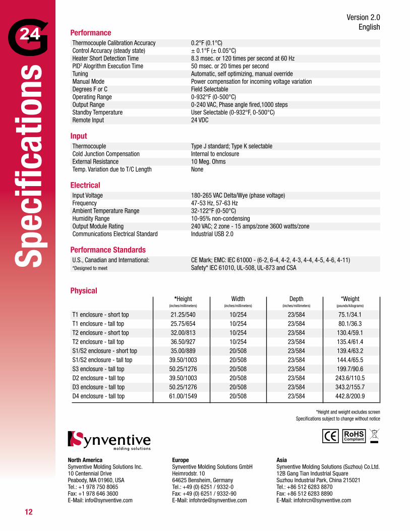
Performance Thermocouple Calibration Accuracy 0.2°F (0.1°C) Control Accuracy (steady state) ± 0.1°F (± 0.05°C) Heater Short Detection Time 8.3 msec. or 120 times per second at 60 Hz PID2 Alogrithm Execution Time 50 msec. or 20 times per second Tuning Automatic, self optimizing, manual override Manual Mode Power compensation for incoming voltage variation Degrees F or C Field Selectable Operating Range 0-932°F (0-500°C) Output Range 0-240 VAC, Phase angle fired,1000 steps Standby Temperature User Selectable (0-932°F, 0-500°C) Remote Input 24 VDC
Input Thermocouple Type J standard; Type K selectable Cold Junction Compensation Internal to enclosure External Resistance 10 Meg. Ohms Temp. Variation due to T/C Length None
Electrical Input Voltage 180-265 VAC Delta/Wye (phase voltage) Frequency 47-53 Hz, 57-63 Hz Ambient Temperature Range 32-122°F (0-50°C) Humidity Range 10-95% non-condensing Output Module Rating 240 VAC; 2 zone - 15 amps/zone 3600 watts/zone Communications Electrical Standard Industrial USB 2.0
Performance Standards U.S., Canadian and International: CE Mark; EMC: IEC 61000 - (6-2, 6-4, 4-2, 4-3, 4-4, 4-5, 4-6, 4-11) *Designed to meet Safety* IEC 61010, UL-508, UL-873 and CSA
Physical *Height Width Depth *Weight (inches/millimeters) (inches/millimeters) (inches/millimeters) (pounds/kilograms)
T1 enclosure - short top 21.25/540 10/254 23/584 75.1/34.1T1 enclosure - tall top 25.75/654 10/254 23/584 80.1/36.3T2 enclosure - short top 32.00/813 10/254 23/584 130.4/59.1T2 enclosure - tall top 36.50/927 10/254 23/584 135.4/61.4S1/S2 enclosure - short top 35.00/889 20/508 23/584 139.4/63.2S1/S2 enclosure - tall top 39.50/1003 20/508 23/584 144.4/65.5S3 enclosure - tall top 50.25/1276 20/508 23/584 199.7/90.6D2 enclosure - tall top 39.50/1003 20/508 23/584 243.6/110.5D3 enclosure - tall top 50.25/1276 20/508 23/584 343.2/155.7D4 enclosure - tall top 61.00/1549 20/508 23/584 442.8/200.9
*Height and weight excludes screenSpecifications subject to change without notice
Spec
ifica
tions
Version 2.0English
North AmericaSynventive Molding Solutions Inc.10 Centennial DrivePeabody, MA 01960, USATel.: +1 978 750 8065Fax: +1 978 646 3600E-Mail: [email protected]
EuropeSynventive Molding Solutions GmbHHeimrodstr. 1064625 Bensheim, GermanyTel.: +49 (0) 6251 / 9332-0Fax: +49 (0) 6251 / 9332-90E-Mail: [email protected]
AsiaSynventive Molding Solutions (Suzhou) Co.Ltd.12B Gang Tian Industrial SquareSuzhou Industrial Park, China 215021Tel.: +86 512 6283 8870Fax: +86 512 6283 8890E-Mail: [email protected]