Embed Size (px)
Citation preview
Halo calculations in ATF DR
Dou Wang (IHEP), Philip Bambade (LAL), Kaoru Yokoya (KEK), Theo Demma (LAL),
Jie Gao (IHEP)
FJPPL-FKPPL Workshop on ATF2 Accelerator
R&D
March 17-19, 2014, Annecy-le-Vieux, France
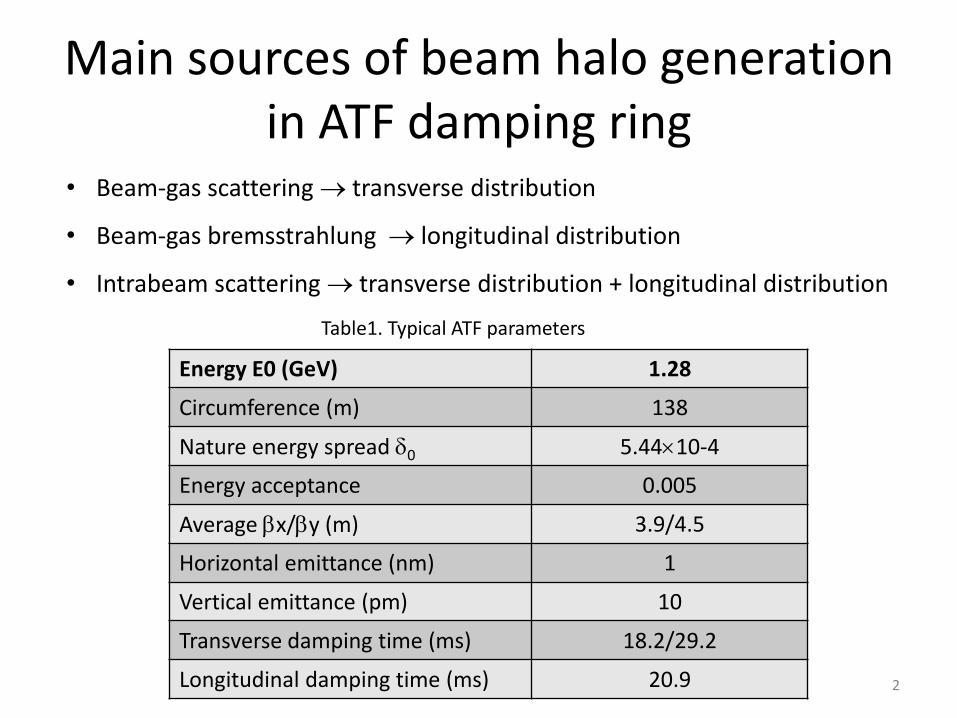
Main sources of beam halo generation in ATF damping ring
• Beam-gas scattering transverse distribution
• Beam-gas bremsstrahlung longitudinal distribution
• Intrabeam scattering transverse distribution + longitudinal distribution
Energy E0 (GeV) 1.28
Circumference (m) 138
Nature energy spread 0 5.4410-4
Energy acceptance 0.005
Average x/y (m) 3.9/4.5
Horizontal emittance (nm) 1
Vertical emittance (pm) 10
Transverse damping time (ms) 18.2/29.2
Longitudinal damping time (ms) 20.9
Table1. Typical ATF parameters
2
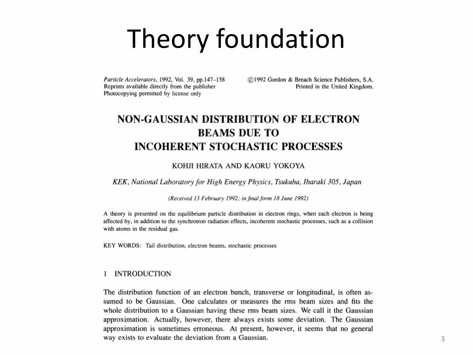
Theory foundation
3
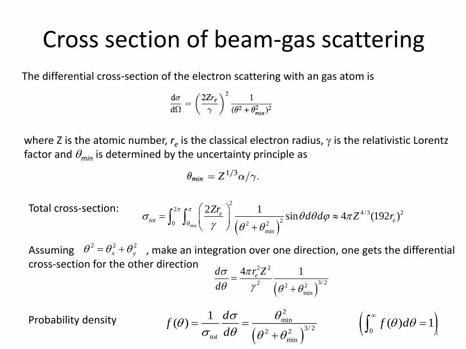
Cross section of beam-gas scattering
min
22
4 / 3 2
20 2 2
min
2 1sin 4 (192 )e
tot e
Zrd d Z r
2 2 2
x y
2 2
3/ 22 2 2
min
4 1ed r Z
d
The differential cross-section of the electron scattering with an gas atom is
where Z is the atomic number, re is the classical electron radius, is the relativistic Lorentz factor and min is determined by the uncertainty principle as
Total cross-section:
Assuming , make an integration over one direction, one gets the differential cross-section for the other direction
2
min
3/ 2 02 2
min
1( ) ( ) 1
tot
df f d
d
Probability density 4
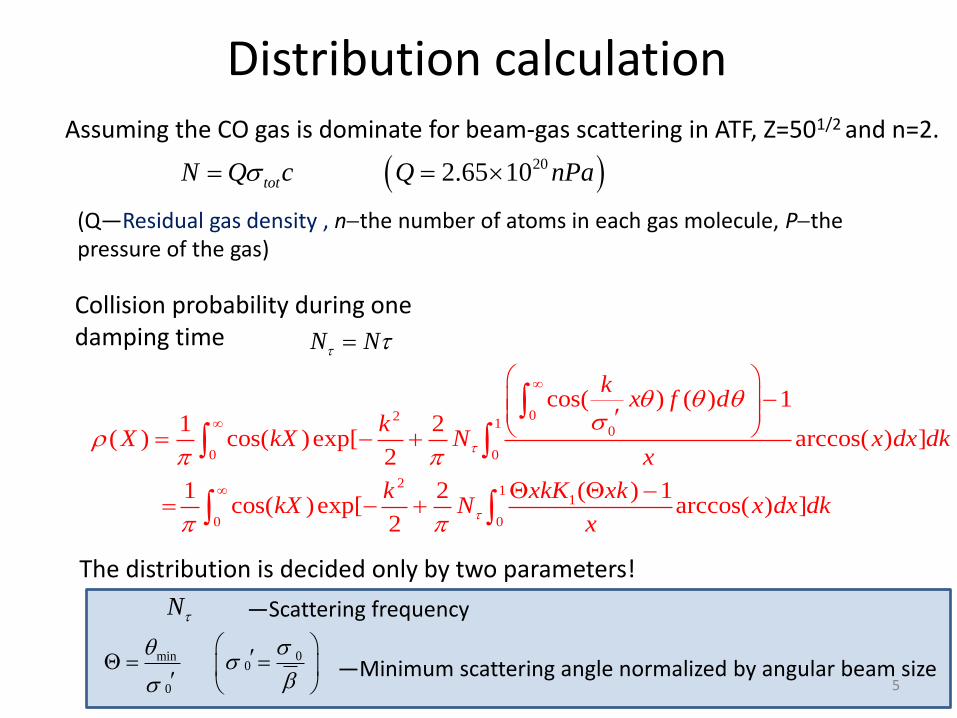
Distribution calculation Assuming the CO gas is dominate for beam-gas scattering in ATF, Z=501/2 and n=2.
202.65 10totN Q c Q nPa
(Q—Residual gas density , nthe number of atoms in each gas molecule, Pthe pressure of the gas)
N N
021
0
0 0
21
1
0 0
cos( ) ( ) 11 2
( ) cos( )exp[ arccos( ) ]2
1 2 ( ) 1cos( )exp[ arccos( ) ]
2
kx f d
kX kX N x dx dk
x
k xkK xkkX N x dx dk
x
Collision probability during one damping time
The distribution is decided only by two parameters!
N
0min0
0
—Scattering frequency
—Minimum scattering angle normalized by angular beam size 5
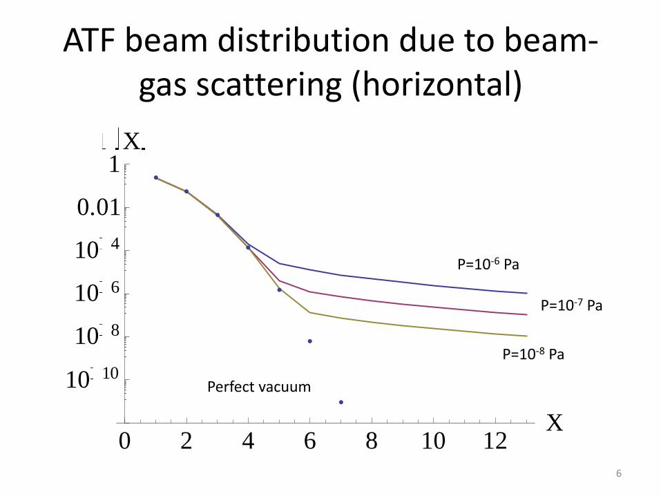
ATF beam distribution due to beam-gas scattering (horizontal)
0 2 4 6 8 10 12X
10 10
10 8
10 6
10 4
0.01
1X
P=10-6 Pa
P=10-7 Pa
P=10-8 Pa
Perfect vacuum
6
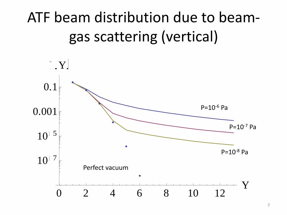
ATF beam distribution due to beam-gas scattering (vertical)
0 2 4 6 8 10 12Y
10 7
10 5
0.001
0.1
Y
P=10-8 Pa
P=10-7 Pa
P=10-6 Pa
Perfect vacuum
7
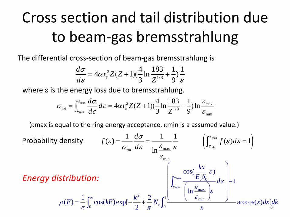
Cross section and tail distribution due to beam-gas bremsstrahlung
2
1/3
4 183 1 14 ( 1)( ln )
3 9e
dr Z Z
d Z
max
min
2 max
1/3
min
4 183 14 ( 1)( ln ) ln
3 9tot e
dd r Z Z
d Z
max
minmax
min
1 1 1( ) ( ) 1
lntot
df f d
d
max
min
0 0
max
21 min
0 0
cos( )
1
ln1 2
( ) cos( )exp[ arccos( ) ]2
kx
Ed
kE kE N x dx dk
x
The differential cross-section of beam-gas bremsstrahlung is
where is the energy loss due to bremsstrahlung.
(max is equal to the ring energy acceptance, min is a assumed value.)
Probability density
Energy distribution:
8
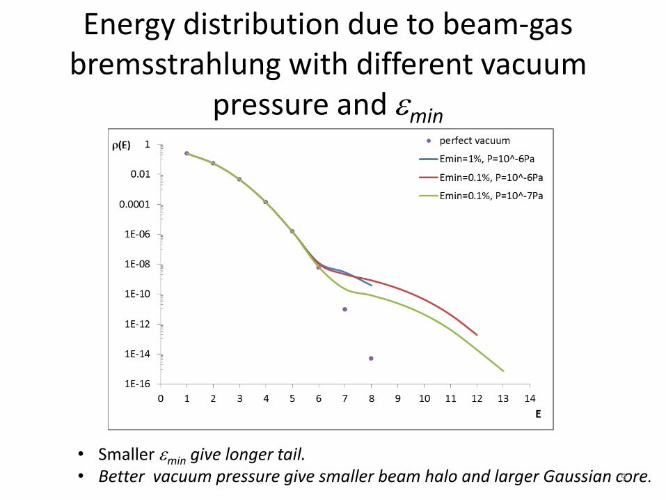
Energy distribution due to beam-gas bremsstrahlung with different vacuum
pressure and min
• Smaller min give longer tail. • Better vacuum pressure give smaller beam halo and larger Gaussian core. 9
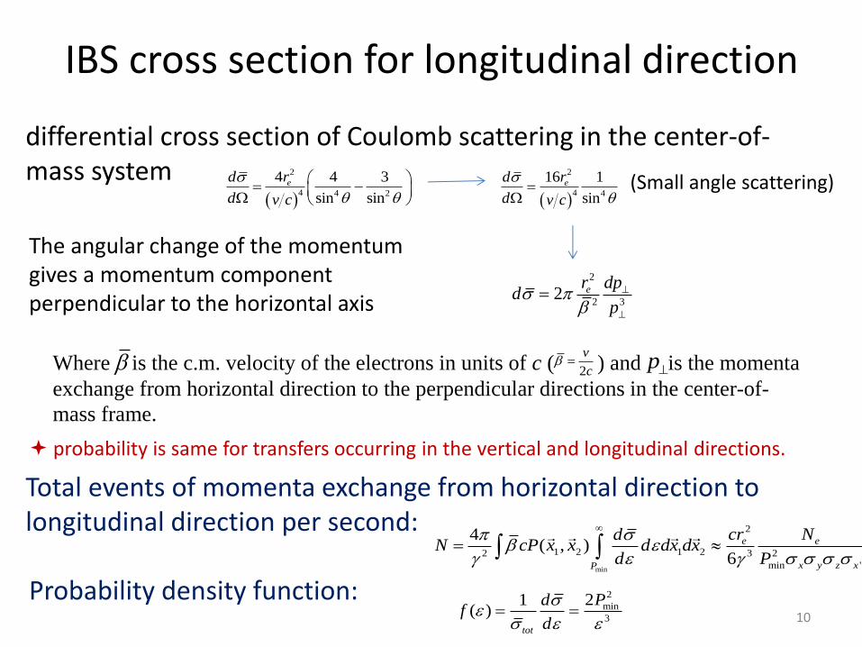
IBS cross section for longitudinal direction
2
4 4 2
4 4 3
sin sin
ed r
d v c
2
4 4
16 1
sin
ed r
d v c
2
2 32 er dp
dp
min
2
1 2 1 22 3 2
min '
4( , )
6
e e
x y z xP
cr NdN cP x x d dx dx
d P
2
min
3
21( )
tot
d
differential cross section of Coulomb scattering in the center-of-mass system (Small angle scattering)
The angular change of the momentum gives a momentum component perpendicular to the horizontal axis
Where is the c.m. velocity of the electrons in units of c ( ) and is the momenta
exchange from horizontal direction to the perpendicular directions in the center-of-
mass frame.
2
v
c p
Total events of momenta exchange from horizontal direction to longitudinal direction per second:
Probability density function:
probability is same for transfers occurring in the vertical and longitudinal directions.
10
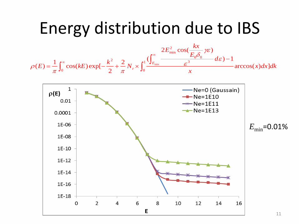
Energy distribution due to IBS
min
2
min
0 02 31
0 0
2 cos( )
( ) 11 2
( ) cos( )exp[ arccos( ) ]2
E
kxE
Ed
kE kE N x dx dk
x
Emin=0.01%
11
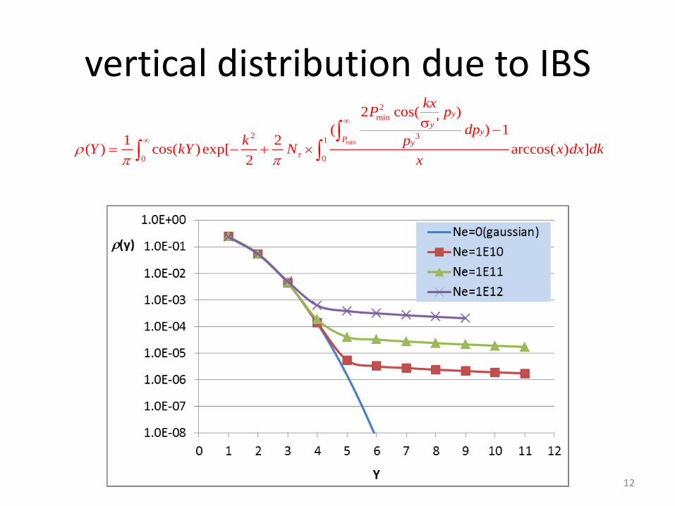
vertical distribution due to IBS
min
2
min
2 31
0 0
2 cos( )'
( ) 11 2
( ) cos( )exp[ arccos( ) ]2
y
yy
P y
kxP p
dpk p
Y kY N x dx dkx
12
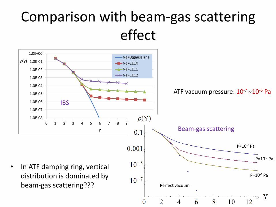
Comparison with beam-gas scattering effect
ATF vacuum pressure: 10-7 10-6 Pa
IBS
Beam-gas scattering
• In ATF damping ring, vertical distribution is dominated by beam-gas scattering???
13
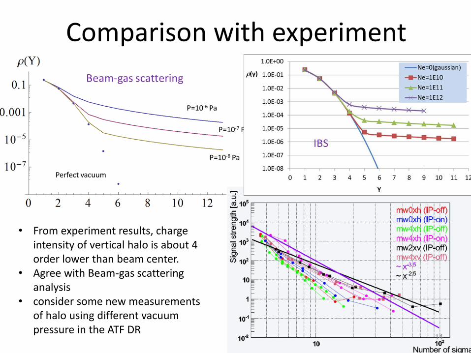
Comparison with experiment
• From experiment results, charge intensity of vertical halo is about 4 order lower than beam center.
• Agree with Beam-gas scattering analysis
• consider some new measurements of halo using different vacuum pressure in the ATF DR
14
IBS simulations by CMAD -check converge time and emittance
• Input equilibrium horizontal emittance x=1.08E-09 mrad, vertical emittance y=5.8E-12 mrad, bunch length z=6.0E-03 m, energy spread =6.0E-04 and bunch charge Ne=1E10
• We did 4 modes simulations to get convergence for:
1) 1000 times shorter damping time and 1000 times higher charge,
2) 100 times shorter damping time and 100 times higher charge,
3) 50 times shorter damping time and 50 times higher charge,
4) 10 times shorter damping time and 10 times higher charge.
By this way we could check if the values of the emittance become closer to the expected ones. If they do, it could be a useful parameter set for future testing, including for the halo tails.
15
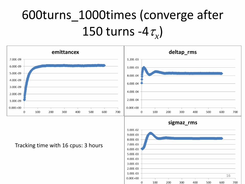
600turns_1000times (converge after 150 turns -4x)
Tracking time with 16 cpus: 3 hours
16
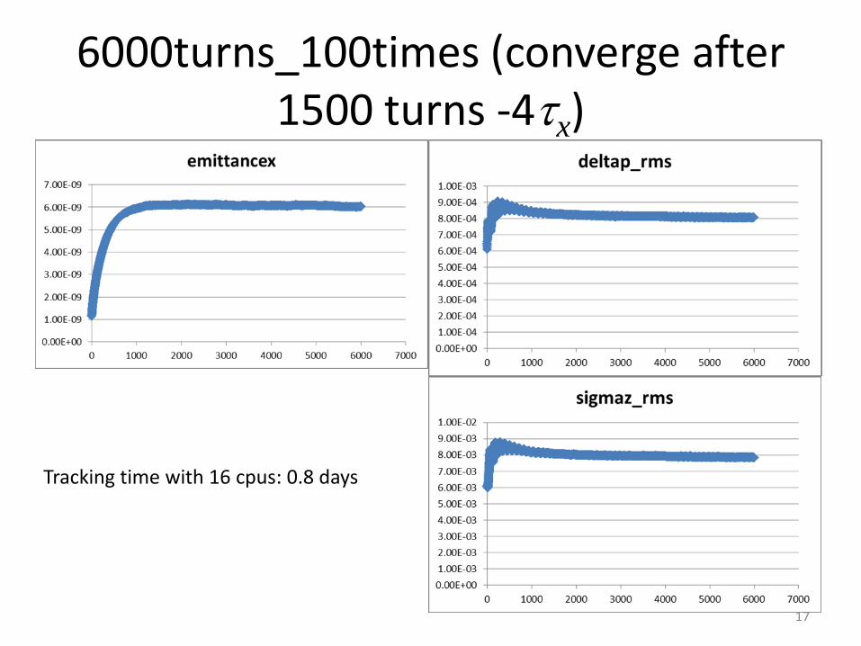
6000turns_100times (converge after 1500 turns -4x)
Tracking time with 16 cpus: 0.8 days
17
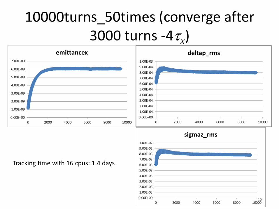
10000turns_50times (converge after 3000 turns -4x)
Tracking time with 16 cpus: 1.4 days
18
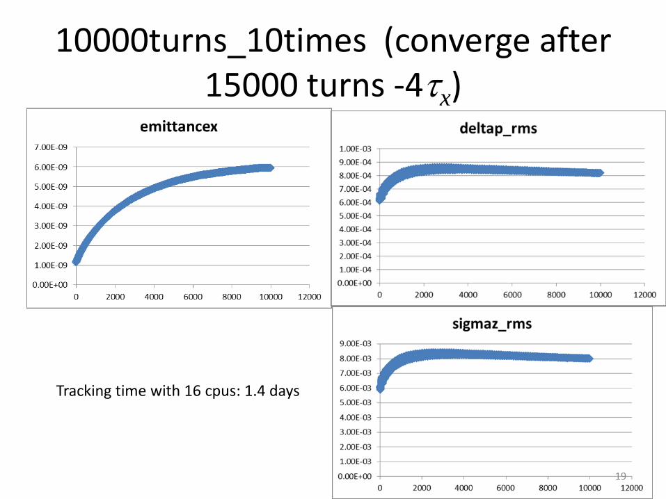
10000turns_10times (converge after 15000 turns -4x)
Tracking time with 16 cpus: 1.4 days
19
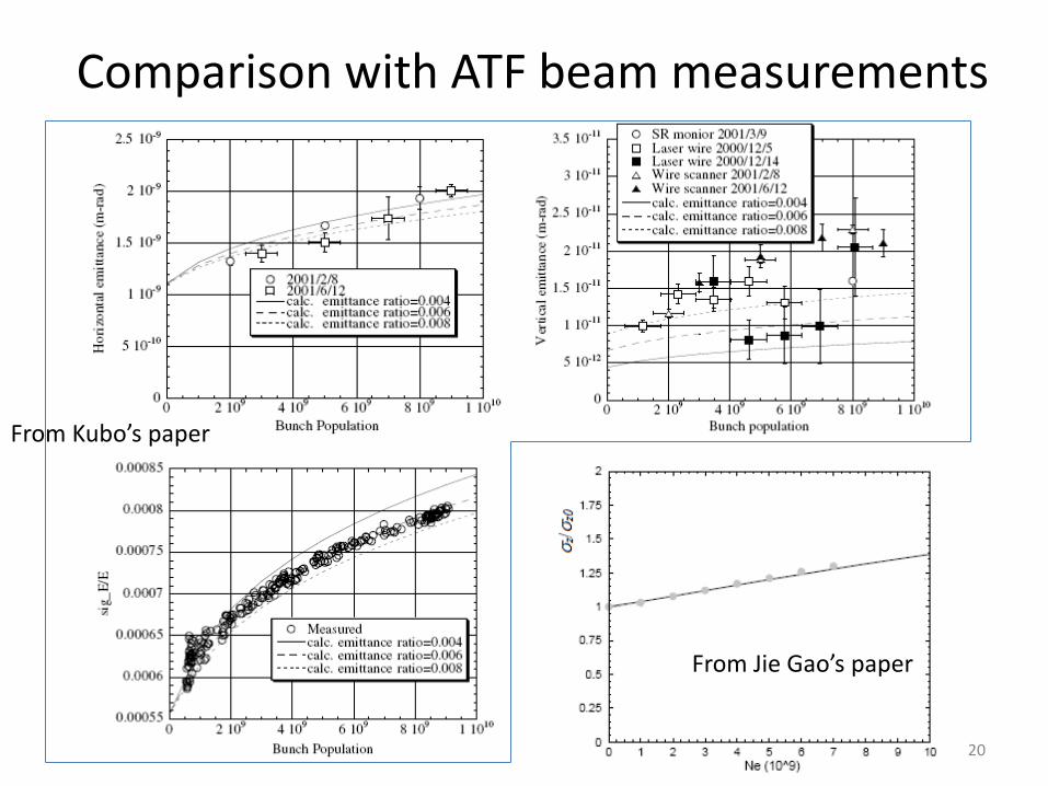
Comparison with ATF beam measurements
From Jie Gao’s paper
From Kubo’s paper
20
Summary and future plan • An analytical method to give the estimation of ATF beam halo
distribution due to beam-gas scattering, beam-gas bremsstrahlung and intra-beam scattering, based on K. Hirata and K. Yokoya’s theory, was developed. This method is rather common and can be applied on other electron rings.
• The study of IBS effect with different horizontal emittance is going on.
• Horizontal distribution due to IBS needs further study. For horizontal distribution, it’s more difficult because there is coupling effect between longitudinal and horizontal.
• IBS simulations were done by CMAD. Horizontal emittance does not agree with the experiments. We are trying to understand and update the source code.
• How can we use CMAD to make halo study? … 21
References
1. Dou Wang, Philip Bambade, Kaoru Yokoya, Jie Gao, “Analytical
estimation of ATF beam halo distribution”,
http://arxiv.org/abs/1311.1267v2.
2. Kohji Hirata and Kaoru Yokoya, “Non-Gaussian Distribution of
Electron Beams due to Incoherent Stochastic Processes”, Pariticle
Accelerators, 1992, Vol. 39, pp. 147-158.
3. Taikan Suehara et. al., “Design of a Nanometer Beam Size
Monitor for ATF2”, http://arxiv.org/abs/0810.5467v1.
22