Embed Size (px)
Citation preview
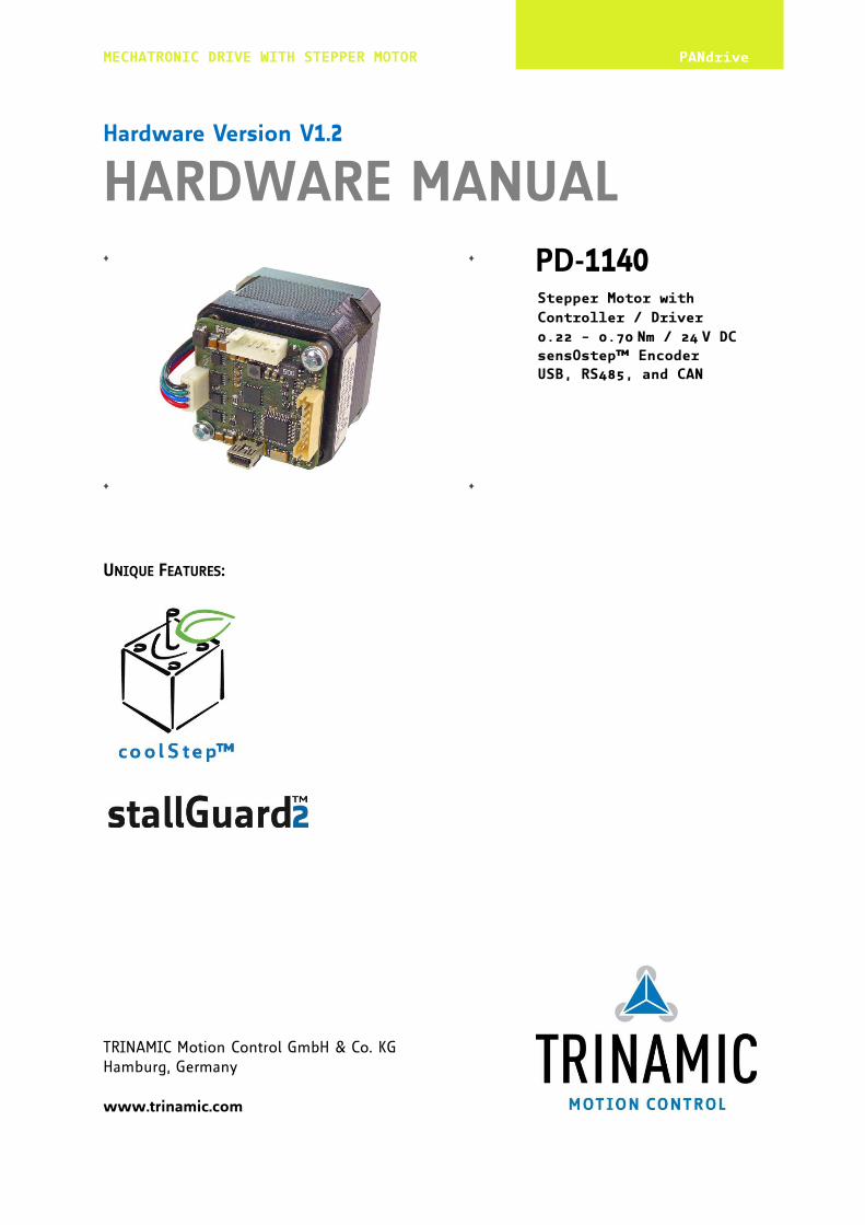
MECHATRONIC DRIVE WITH STEPPER MOTOR PANdrive
TRINAMIC Motion Control GmbH & Co. KG Hamburg, Germany www.trinamic.com
Hardware Version V1.2
HARDWARE MANUAL
+ + PD-1140
+ +
UNIQUE FEATURES:
Stepper Motor with
Controller / Driver
0.22 - 0.70 Nm / 24 V DC
sensOstep™ Encoder
USB, RS485, and CAN
PD-1140 Hardware Manual (Rev. 1.02 / 2013-MAR-26) 2
www.trinamic.com
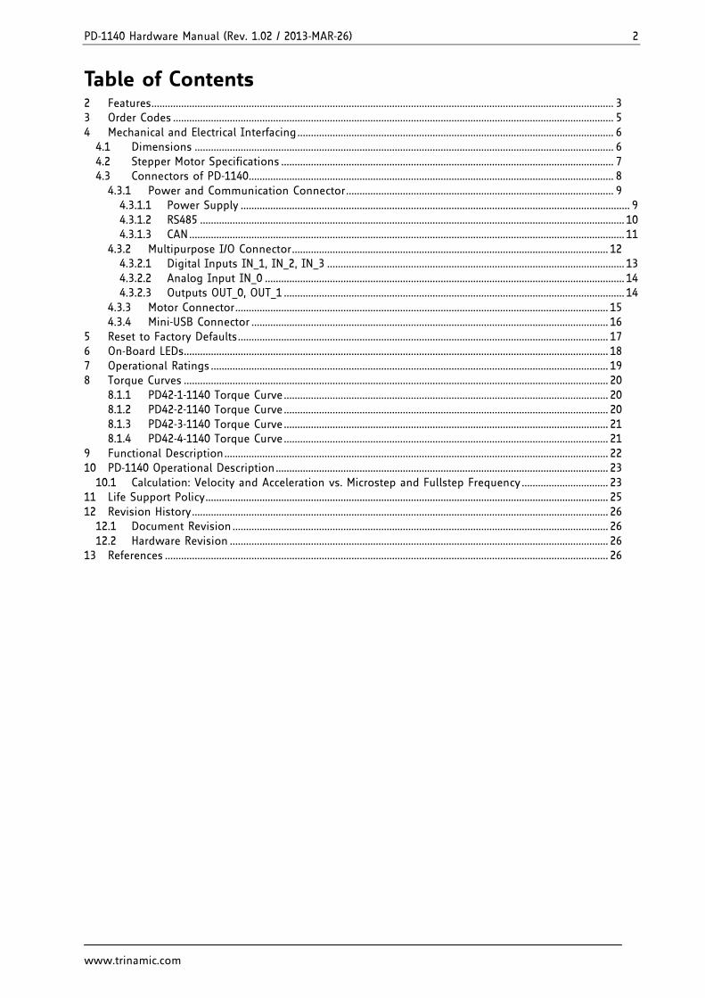
Table of Contents 2 Features ........................................................................................................................................................................... 3 3 Order Codes ................................................................................................................................................................... 5 4 Mechanical and Electrical Interfacing ..................................................................................................................... 6
4.1 Dimensions ........................................................................................................................................................... 6 4.2 Stepper Motor Specifications ........................................................................................................................... 7 4.3 Connectors of PD-1140 ....................................................................................................................................... 8
4.3.1 Power and Communication Connector ................................................................................................... 9 4.3.1.1 Power Supply ................................................................................................................................................ 9 4.3.1.2 RS485 ............................................................................................................................................................. 10 4.3.1.3 CAN ................................................................................................................................................................. 11
4.3.2 Multipurpose I/O Connector ..................................................................................................................... 12 4.3.2.1 Digital Inputs IN_1, IN_2, IN_3 .............................................................................................................. 13 4.3.2.2 Analog Input IN_0 ..................................................................................................................................... 14 4.3.2.3 Outputs OUT_0, OUT_1 .............................................................................................................................. 14
4.3.3 Motor Connector .......................................................................................................................................... 15 4.3.4 Mini-USB Connector .................................................................................................................................... 16
5 Reset to Factory Defaults ......................................................................................................................................... 17 6 On-Board LEDs............................................................................................................................................................. 18 7 Operational Ratings ................................................................................................................................................... 19 8 Torque Curves ............................................................................................................................................................. 20
8.1.1 PD42-1-1140 Torque Curve ........................................................................................................................ 20 8.1.2 PD42-2-1140 Torque Curve ........................................................................................................................ 20 8.1.3 PD42-3-1140 Torque Curve ........................................................................................................................ 21 8.1.4 PD42-4-1140 Torque Curve ........................................................................................................................ 21
9 Functional Description .............................................................................................................................................. 22 10 PD-1140 Operational Description ........................................................................................................................... 23
10.1 Calculation: Velocity and Acceleration vs. Microstep and Fullstep Frequency ................................ 23 11 Life Support Policy ..................................................................................................................................................... 25 12 Revision History .......................................................................................................................................................... 26
12.1 Document Revision ........................................................................................................................................... 26 12.2 Hardware Revision ............................................................................................................................................ 26
13 References .................................................................................................................................................................... 26
PD-1140 Hardware Manual (Rev. 1.02 / 2013-MAR-26) 3
www.trinamic.com
2 Features The PANdrive™ PD-1140 is a full mechatronic solution with state of the art feature set. It is highly integrated and offers a convenient handling. The PD-1140 includes a stepper motor, controller/driver electronics, and TRINAMICs sensOstep™ encoder. It can be used in many decentralized applications and has been designed for 0.20… 0.70 Nm max. holding torque and 24V DC nominal supply voltage. With its high energy efficiency from TRINAMICs coolStep technology cost for power consumption is kept down. The TMCL™ firmware allows for standalone operation and direct mode.
MAIN CHARACTERISTICS
Motion controller Motion profile calculation in real-time On the fly alteration of motor parameters (e.g. position, velocity, acceleration) High performance microcontroller for overall system control and serial communication protocol
handling Bipolar stepper motor driver Up to 256 microsteps per full step High-efficient operation, low power dissipation Dynamic current control Integrated protection stallGuard2 feature for stall detection coolStep feature for reduced power consumption and heat dissipation Encoder sensOstep magnetic encoder (1024 increments per rotation) e.g. for step-loss detection under all
operating conditions and positioning supervision Interfaces RS485 2-wire communication interface CAN 2.0B communication interface USB full speed (12Mbit/s) device interface 4 multipurpose inputs:
- 3x general-purpose digital inputs (Alternate functions: STOP_L / STOP_R / HOME switch inputs or A/B/N encoder input)
- 1x dedicated analog input 2 general purpose outputs
- 1x open-drain 1A max. - 1x +5V supply output (can be switched on/off in software)
Software TMCL: standalone operation or remote controlled operation,
program memory (non volatile) for up to 2048 TMCL commands, and PC-based application development software TMCL-IDE available for free.
Electrical and mechanical data Supply voltage: +24 V DC nominal (9… 28 V DC) Motor current: up to 2 A RMS / 2.8 A peak (programmable) 0.22… 0.70 Nm max. holding torque (depends on motor) Refer to separate TMCL Firmware Manual, too.
PD-1140 Hardware Manual (Rev. 1.02 / 2013-MAR-26) 4
www.trinamic.com
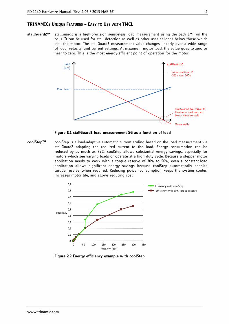
TRINAMICS UNIQUE FEATURES – EASY TO USE WITH TMCL stallGuard2™ stallGuard2 is a high-precision sensorless load measurement using the back EMF on the
coils. It can be used for stall detection as well as other uses at loads below those which stall the motor. The stallGuard2 measurement value changes linearly over a wide range of load, velocity, and current settings. At maximum motor load, the value goes to zero or near to zero. This is the most energy-efficient point of operation for the motor.
Load [Nm]
stallGuard2
Initial stallGuard2 (SG) value: 100%
Max. load
stallGuard2 (SG) value: 0Maximum load reached. Motor close to stall.
Motor stalls
Figure 2.1 stallGuard2 load measurement SG as a function of load coolStep™ coolStep is a load-adaptive automatic current scaling based on the load measurement via
stallGuard2 adapting the required current to the load. Energy consumption can be reduced by as much as 75%. coolStep allows substantial energy savings, especially for motors which see varying loads or operate at a high duty cycle. Because a stepper motor application needs to work with a torque reserve of 30% to 50%, even a constant-load application allows significant energy savings because coolStep automatically enables torque reserve when required. Reducing power consumption keeps the system cooler, increases motor life, and allows reducing cost.
0
0,1
0,2
0,3
0,4
0,5
0,6
0,7
0,8
0,9
0 50 100 150 200 250 300 350
Efficiency
Velocity [RPM]
Efficiency with coolStep
Efficiency with 50% torque reserve
Figure 2.2 Energy efficiency example with coolStep
PD-1140 Hardware Manual (Rev. 1.02 / 2013-MAR-26) 5
www.trinamic.com
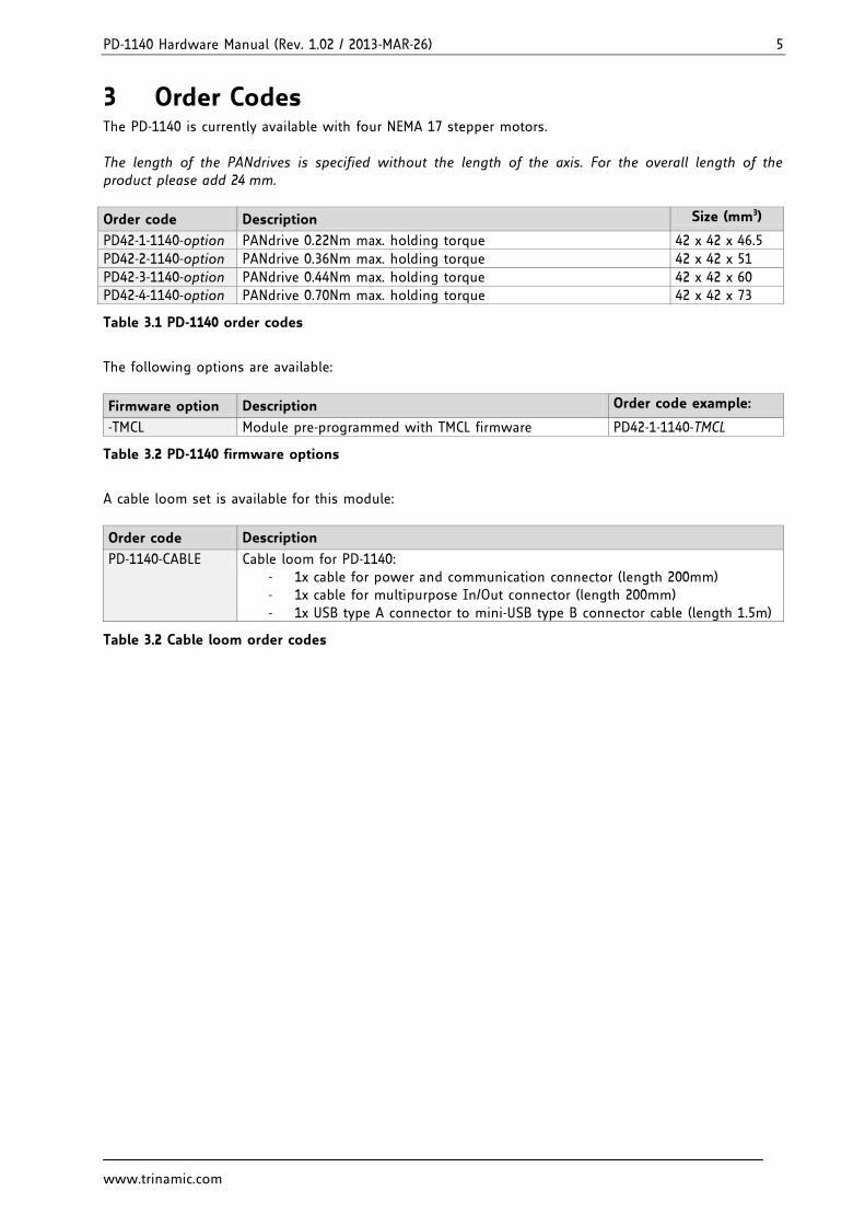
3 Order Codes The PD-1140 is currently available with four NEMA 17 stepper motors. The length of the PANdrives is specified without the length of the axis. For the overall length of the product please add 24 mm.
Order code Description Size (mm3)
PD42-1-1140-option PANdrive 0.22Nm max. holding torque 42 x 42 x 46.5
PD42-2-1140-option PANdrive 0.36Nm max. holding torque 42 x 42 x 51
PD42-3-1140-option PANdrive 0.44Nm max. holding torque 42 x 42 x 60
PD42-4-1140-option PANdrive 0.70Nm max. holding torque 42 x 42 x 73
Table 3.1 PD-1140 order codes
The following options are available:
Firmware option Description Order code example:
-TMCL Module pre-programmed with TMCL firmware PD42-1-1140-TMCL
Table 3.2 PD-1140 firmware options
A cable loom set is available for this module:
Order code Description
PD-1140-CABLE Cable loom for PD-1140: 1x cable for power and communication connector (length 200mm) - 1x cable for multipurpose In/Out connector (length 200mm) - 1x USB type A connector to mini-USB type B connector cable (length 1.5m)
Table 3.2 Cable loom order codes
PD-1140 Hardware Manual (Rev. 1.02 / 2013-MAR-26) 6
www.trinamic.com
4 Mechanical and Electrical Interfacing
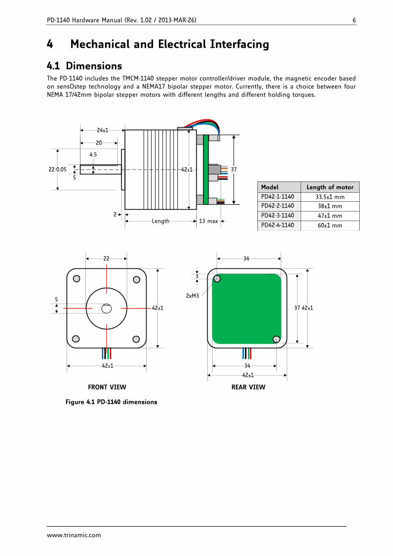
4.1 Dimensions The PD-1140 includes the TMCM-1140 stepper motor controller/driver module, the magnetic encoder based on sensOstep technology and a NEMA17 bipolar stepper motor. Currently, there is a choice between four NEMA 17/42mm bipolar stepper motors with different lengths and different holding torques.
Length
42±1
2
22-0.05
24±1
20
5
4.5
13 max
37
22
42±1
42±1
5
42±1
34
2xM3
42±1
37
34
3
FRONT VIEW REAR VIEW
Figure 4.1 PD-1140 dimensions
Model Length of motor
PD42-1-1140 33.5±1 mm
PD42-2-1140 38±1 mm
PD42-3-1140 47±1 mm
PD42-4-1140 60±1 mm
PD-1140 Hardware Manual (Rev. 1.02 / 2013-MAR-26) 7
www.trinamic.com
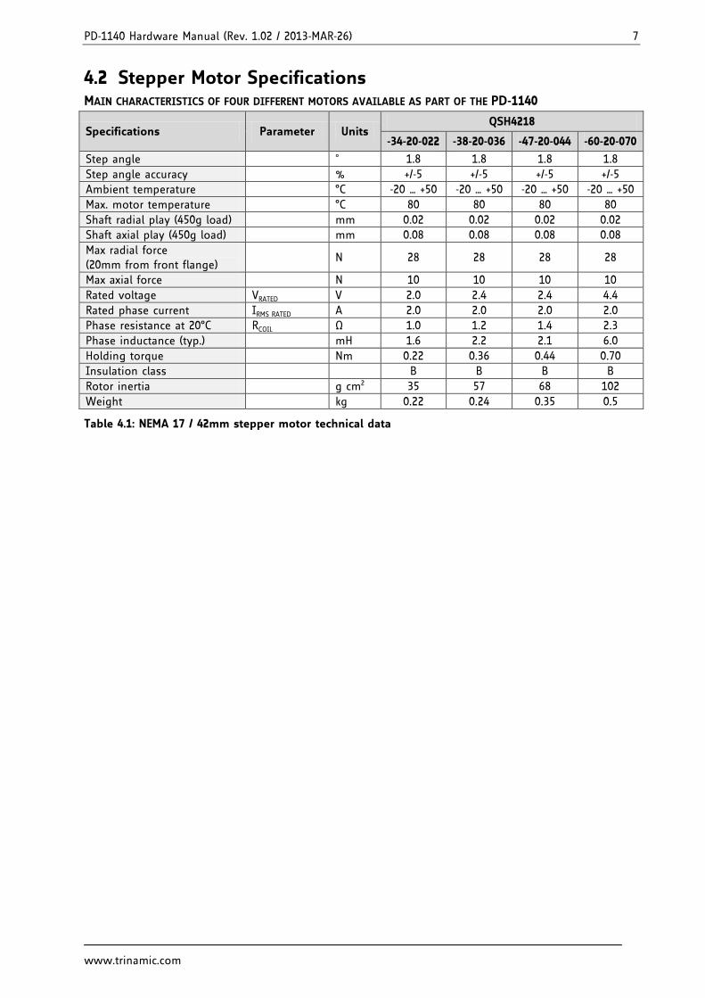
4.2 Stepper Motor Specifications MAIN CHARACTERISTICS OF FOUR DIFFERENT MOTORS AVAILABLE AS PART OF THE PD-1140
Specifications Parameter Units QSH4218
-34-20-022 -38-20-036 -47-20-044 -60-20-070
Step angle ˚ 1.8 1.8 1.8 1.8
Step angle accuracy % +/-5 +/-5 +/-5 +/-5
Ambient temperature °C -20 … +50 -20 … +50 -20 … +50 -20 … +50
Max. motor temperature °C 80 80 80 80
Shaft radial play (450g load) mm 0.02 0.02 0.02 0.02
Shaft axial play (450g load) mm 0.08 0.08 0.08 0.08
Max radial force (20mm from front flange)
N 28 28 28 28
Max axial force N 10 10 10 10
Rated voltage VRATED V 2.0 2.4 2.4 4.4
Rated phase current IRMS RATED A 2.0 2.0 2.0 2.0
Phase resistance at 20°C RCOIL Ω 1.0 1.2 1.4 2.3
Phase inductance (typ.) mH 1.6 2.2 2.1 6.0
Holding torque Nm 0.22 0.36 0.44 0.70
Insulation class B B B B
Rotor inertia g cm2 35 57 68 102
Weight kg 0.22 0.24 0.35 0.5
Table 4.1: NEMA 17 / 42mm stepper motor technical data
PD-1140 Hardware Manual (Rev. 1.02 / 2013-MAR-26) 8
www.trinamic.com
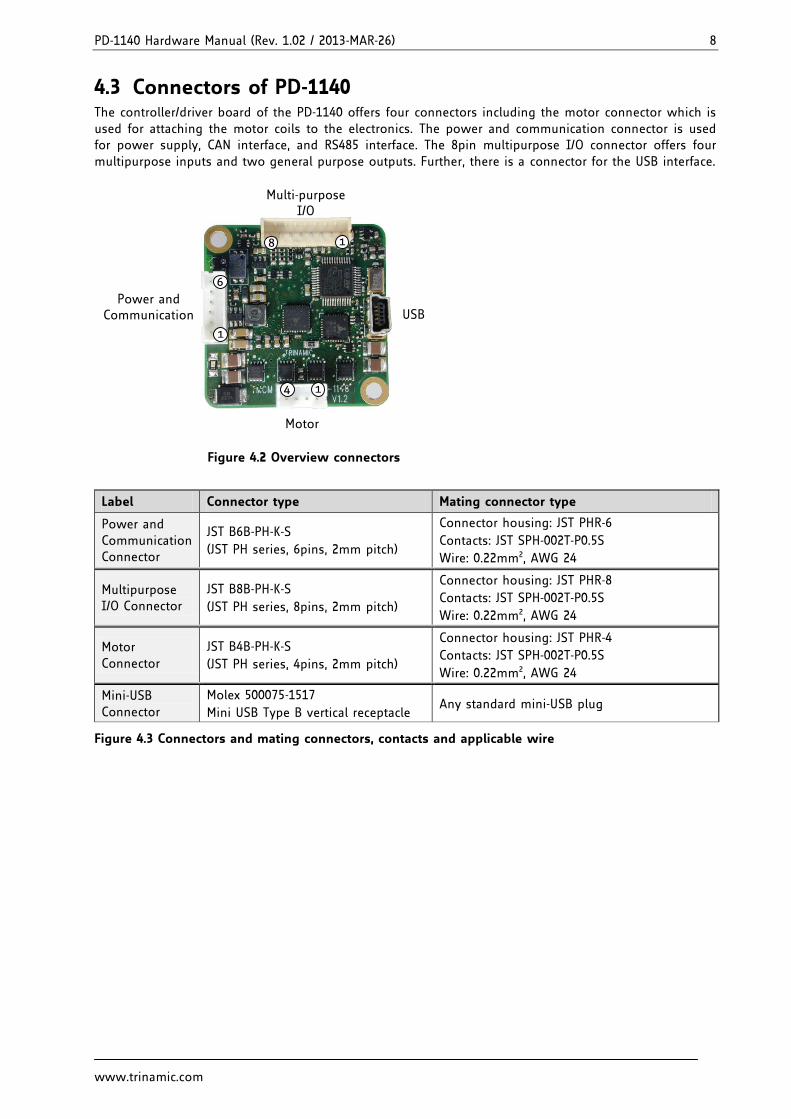
4.3 Connectors of PD-1140 The controller/driver board of the PD-1140 offers four connectors including the motor connector which is used for attaching the motor coils to the electronics. The power and communication connector is used for power supply, CAN interface, and RS485 interface. The 8pin multipurpose I/O connector offers four multipurpose inputs and two general purpose outputs. Further, there is a connector for the USB interface.
USB
Motor
14
Multi-purposeI/O
18
Power andCommunication
1
6
Figure 4.2 Overview connectors
Label Connector type Mating connector type
Power and Communication Connector
JST B6B-PH-K-S
(JST PH series, 6pins, 2mm pitch)
Connector housing: JST PHR-6
Contacts: JST SPH-002T-P0.5S
Wire: 0.22mm2, AWG 24
Multipurpose I/O Connector
JST B8B-PH-K-S
(JST PH series, 8pins, 2mm pitch)
Connector housing: JST PHR-8
Contacts: JST SPH-002T-P0.5S
Wire: 0.22mm2, AWG 24
Motor Connector
JST B4B-PH-K-S
(JST PH series, 4pins, 2mm pitch)
Connector housing: JST PHR-4
Contacts: JST SPH-002T-P0.5S
Wire: 0.22mm2, AWG 24
Mini-USB Connector
Molex 500075-1517
Mini USB Type B vertical receptacle Any standard mini-USB plug
Figure 4.3 Connectors and mating connectors, contacts and applicable wire
PD-1140 Hardware Manual (Rev. 1.02 / 2013-MAR-26) 9
www.trinamic.com
4.3.1 Power and Communication Connector A 6pin JST PH-series 2mm pitch single row connector is used for power supply, RS485 and CAN serial communication. Please note the additional power supply information in chapter 4.3.1.1.
Note: CAN interface will be de-activated in case USB is connected due to internal sharing of hardware resources.
61
Pin Label Direction Description
1 GND Power (GND) System and signal ground
2 VDD Power (Supply) VDD (+9V…+28V)
3 RS485+ Bidirectional RS485 interface, diff. signal (non-inverting)
4 RS485- Bidirectional RS485 interface, diff. signal (inverting)
5 CAN_H Bidirectional CAN interface, diff. signal (non-inverting)
6 CAN_L Bidirectional CAN interface, diff. signal (inverting)
Table 4.1 Connector for power supply and interfaces
4.3.1.1 Power Supply For proper operation care has to be taken with regard to power supply concept and design. Due to space restrictions the TMCM-1140 includes about 40µF/35V of supply filter capacitors. These are ceramic capacitors which have been selected for high reliability and long life time. The module includes a 28V suppressor diode for over-voltage protection. There is no reverse polarity protection. The module will short any reversed supply voltage due to the suppressor diode (uni-directional version) and the internal diodes of the driver transistors. It is important that the power supply voltage is kept below the upper limit of 28V (please see also chapter 6, operating values). Otherwise the driver electronics might be seriously damaged! Especially, when the selected operating voltage is near the upper limit a regulated power supply is highly recommended.
It is recommended to connect an electrolytic capacitor of significant size (e.g. 470µF/35V) to the power supply lines next to the PD42-1140!
In addition to power stabilization (buffer) and filtering this added capacitor will also reduce any voltage spikes which might otherwise occur from a combination of high inductance power supply wires and the ceramic capacitors. In addition it will limit slew-rate of power supply voltage at the module. The low ESR of ceramic-only filter capacitors may cause stability problems with some switching power supplies.
PD-1140 Hardware Manual (Rev. 1.02 / 2013-MAR-26) 10
www.trinamic.com
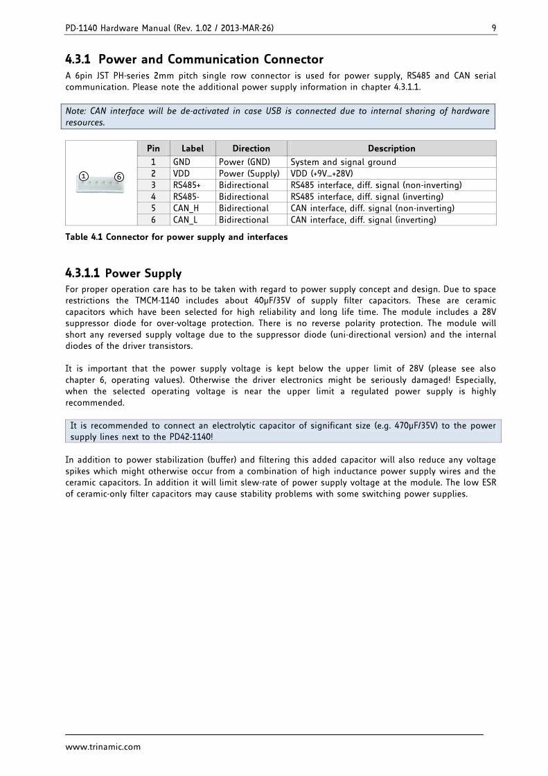
4.3.1.2 RS485 For remote control and communication with a host system the TMCM-1140 provides a two wire RS485 bus interface. For proper operation the following items should be taken into account when setting up an RS485 network:
1. BUS STRUCTURE: The network topology should follow a bus structure as closely as possible. That is, the connection between each node and the bus itself should be as short as possible. Basically, it should be short compared to the length of the bus.
c:>node
1noden - 1
noden
HostSlave Slave Slave
RS485
terminationresistor
(120 Ohm)
terminationresistor
(120 Ohm)
keep distance asshort as possible
Figure 4.4 Bus structure
2. BUS TERMINATION:
Especially for longer busses and/or multiple nodes connected to the bus and/or high communication speeds, the bus should be properly terminated at both ends. The TMCM-1140 does not integrate any termination resistor. Therefore, 120 Ohm termination resistors at both ends of the bus have to be added externally.
3. NUMBER OF NODES:
The RS485 electrical interface standard (EIA-485) allows up to 32 nodes to be connected to a single bus. The bus transceiver used on the PD-1140 units (SN65HVD3082ED) has just 1/8th of the standard bus load and allows a maximum of 256 units to be connected to a single RS485 bus.
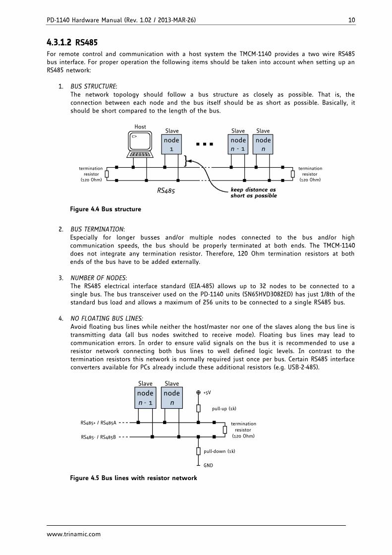
4. NO FLOATING BUS LINES:
Avoid floating bus lines while neither the host/master nor one of the slaves along the bus line is transmitting data (all bus nodes switched to receive mode). Floating bus lines may lead to communication errors. In order to ensure valid signals on the bus it is recommended to use a resistor network connecting both bus lines to well defined logic levels. In contrast to the termination resistors this network is normally required just once per bus. Certain RS485 interface converters available for PCs already include these additional resistors (e.g. USB-2-485).
noden - 1
noden
Slave Slave
terminationresistor
(120 Ohm)
+5V
GND
pull-up (1k)
pull-down (1k)
RS485- / RS485B
RS485+ / RS485A
Figure 4.5 Bus lines with resistor network
PD-1140 Hardware Manual (Rev. 1.02 / 2013-MAR-26) 11
www.trinamic.com
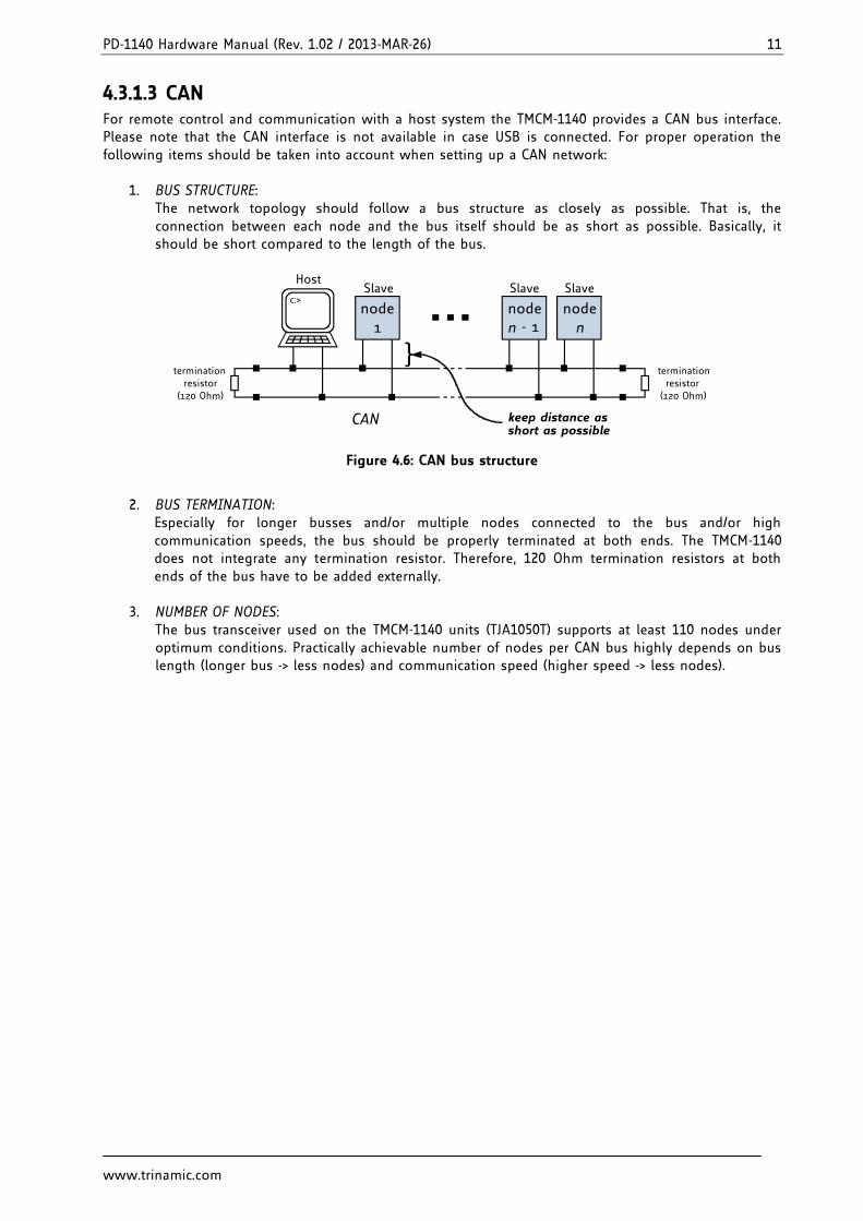
4.3.1.3 CAN For remote control and communication with a host system the TMCM-1140 provides a CAN bus interface. Please note that the CAN interface is not available in case USB is connected. For proper operation the following items should be taken into account when setting up a CAN network:
1. BUS STRUCTURE: The network topology should follow a bus structure as closely as possible. That is, the connection between each node and the bus itself should be as short as possible. Basically, it should be short compared to the length of the bus.
c:>node
1noden - 1
noden
HostSlave Slave Slave
CAN
terminationresistor
(120 Ohm)
terminationresistor
(120 Ohm)
keep distance asshort as possible
Figure 4.6: CAN bus structure
2. BUS TERMINATION:
Especially for longer busses and/or multiple nodes connected to the bus and/or high communication speeds, the bus should be properly terminated at both ends. The TMCM-1140 does not integrate any termination resistor. Therefore, 120 Ohm termination resistors at both ends of the bus have to be added externally.
3. NUMBER OF NODES:
The bus transceiver used on the TMCM-1140 units (TJA1050T) supports at least 110 nodes under optimum conditions. Practically achievable number of nodes per CAN bus highly depends on bus length (longer bus -> less nodes) and communication speed (higher speed -> less nodes).
PD-1140 Hardware Manual (Rev. 1.02 / 2013-MAR-26) 12
www.trinamic.com
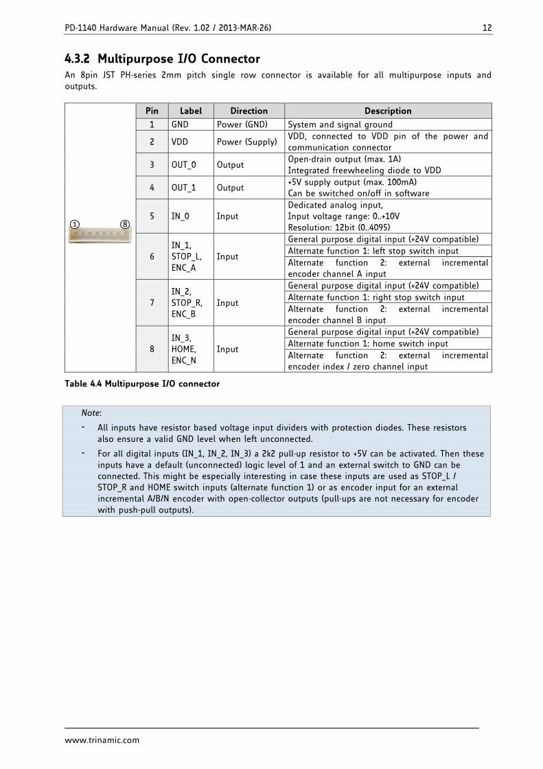
4.3.2 Multipurpose I/O Connector An 8pin JST PH-series 2mm pitch single row connector is available for all multipurpose inputs and outputs.
81
Pin Label Direction Description
1 GND Power (GND) System and signal ground
2 VDD Power (Supply) VDD, connected to VDD pin of the power and communication connector
3 OUT_0 Output Open-drain output (max. 1A) Integrated freewheeling diode to VDD
4 OUT_1 Output +5V supply output (max. 100mA) Can be switched on/off in software
5 IN_0 Input Dedicated analog input, Input voltage range: 0..+10V Resolution: 12bit (0..4095)
6 IN_1, STOP_L, ENC_A
Input
General purpose digital input (+24V compatible)
Alternate function 1: left stop switch input
Alternate function 2: external incremental encoder channel A input
7 IN_2, STOP_R, ENC_B
Input
General purpose digital input (+24V compatible)
Alternate function 1: right stop switch input
Alternate function 2: external incremental encoder channel B input
8 IN_3, HOME, ENC_N
Input
General purpose digital input (+24V compatible)
Alternate function 1: home switch input
Alternate function 2: external incremental encoder index / zero channel input
Table 4.4 Multipurpose I/O connector
Note:
- All inputs have resistor based voltage input dividers with protection diodes. These resistors also ensure a valid GND level when left unconnected.
- For all digital inputs (IN_1, IN_2, IN_3) a 2k2 pull-up resistor to +5V can be activated. Then these inputs have a default (unconnected) logic level of 1 and an external switch to GND can be connected. This might be especially interesting in case these inputs are used as STOP_L / STOP_R and HOME switch inputs (alternate function 1) or as encoder input for an external incremental A/B/N encoder with open-collector outputs (pull-ups are not necessary for encoder with push-pull outputs).
PD-1140 Hardware Manual (Rev. 1.02 / 2013-MAR-26) 13
www.trinamic.com
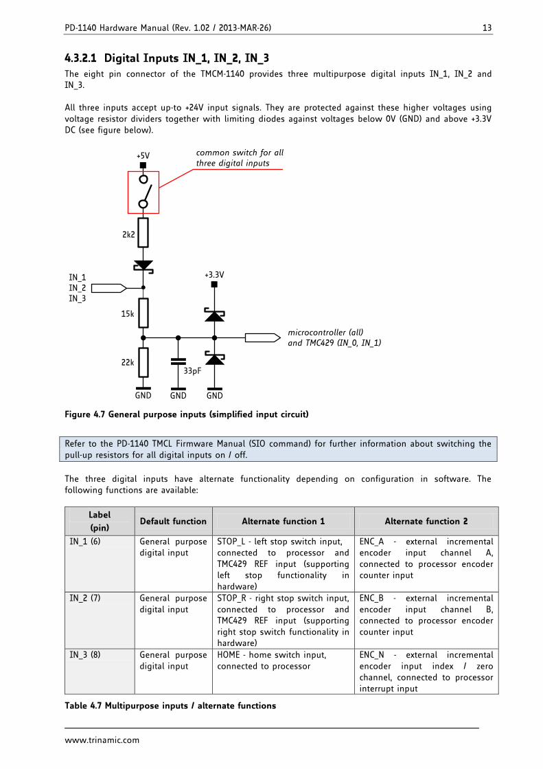
4.3.2.1 Digital Inputs IN_1, IN_2, IN_3
The eight pin connector of the TMCM-1140 provides three multipurpose digital inputs IN_1, IN_2 and IN_3. All three inputs accept up-to +24V input signals. They are protected against these higher voltages using voltage resistor dividers together with limiting diodes against voltages below 0V (GND) and above +3.3V DC (see figure below).
+3.3VIN_1IN_2IN_3
microcontroller (all)and TMC429 (IN_0, IN_1)
15k
22k33pF
GND GND GND
common switch for allthree digital inputs
2k2
+5V
Figure 4.7 General purpose inputs (simplified input circuit)
Refer to the PD-1140 TMCL Firmware Manual (SIO command) for further information about switching the pull-up resistors for all digital inputs on / off.
The three digital inputs have alternate functionality depending on configuration in software. The following functions are available:
Label
(pin) Default function Alternate function 1 Alternate function 2
IN_1 (6) General purpose digital input
STOP_L - left stop switch input, connected to processor and TMC429 REF input (supporting left stop functionality in hardware)
ENC_A - external incremental encoder input channel A, connected to processor encoder counter input
IN_2 (7) General purpose digital input
STOP_R - right stop switch input, connected to processor and TMC429 REF input (supporting right stop switch functionality in hardware)
ENC_B - external incremental encoder input channel B, connected to processor encoder counter input
IN_3 (8) General purpose digital input
HOME - home switch input, connected to processor
ENC_N - external incremental encoder input index / zero channel, connected to processor interrupt input
Table 4.7 Multipurpose inputs / alternate functions
PD-1140 Hardware Manual (Rev. 1.02 / 2013-MAR-26) 14
www.trinamic.com
All three digital inputs are connected to the on-board processor and can be used as general purpose digital inputs (default).
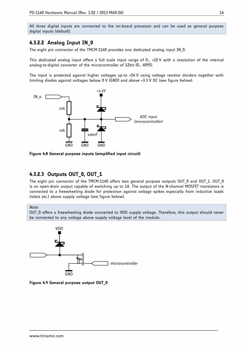
4.3.2.2 Analog Input IN_0 The eight pin connector of the TMCM-1140 provides one dedicated analog input IN_0. This dedicated analog input offers a full scale input range of 0… +10 V with a resolution of the internal analog-to-digital converter of the microcontroller of 12bit (0… 4095). The input is protected against higher voltages up-to +24 V using voltage resistor dividers together with limiting diodes against voltages below 0 V (GND) and above +3.3 V DC (see figure below).
+3.3V
IN_0
ADC input (microcontroller)
22k
10k100nF
GND GND GND
Figure 4.8 General purpose inputs (simplified input circuit)
4.3.2.3 Outputs OUT_0, OUT_1 The eight pin connector of the TMCM-1140 offers two general purpose outputs OUT_0 and OUT_1. OUT_0 is an open-drain output capable of switching up to 1A. The output of the N-channel MOSFET transistors is connected to a freewheeling diode for protection against voltage spikes especially from inductive loads (relais etc.) above supply voltage (see figure below).
Note: OUT_0 offers a freewheeling diode connected to VDD supply voltage. Therefore, this output should never be connected to any voltage above supply voltage level of the module.
VDD
microcontroller
GND
Figure 4.9 General purpose output OUT_0
PD-1140 Hardware Manual (Rev. 1.02 / 2013-MAR-26) 15
www.trinamic.com
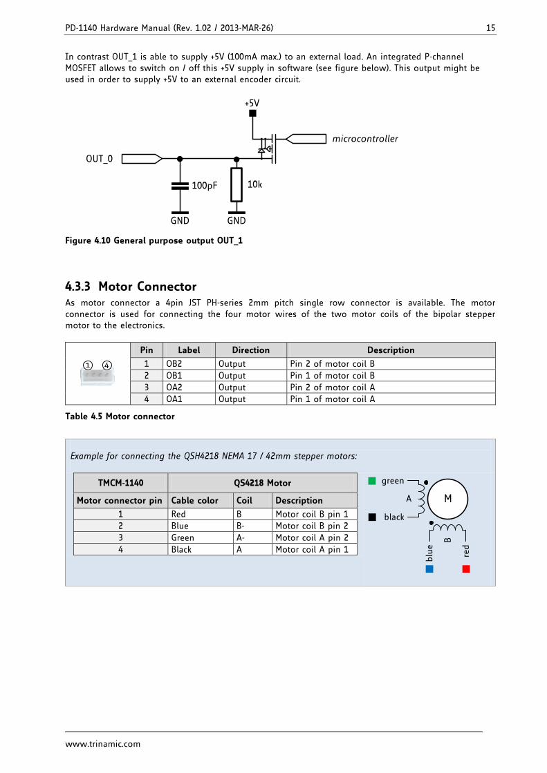
In contrast OUT_1 is able to supply +5V (100mA max.) to an external load. An integrated P-channel MOSFET allows to switch on / off this +5V supply in software (see figure below). This output might be used in order to supply +5V to an external encoder circuit.
+5V
microcontroller
GND
OUT_0
GND
100pF 10k
Figure 4.10 General purpose output OUT_1
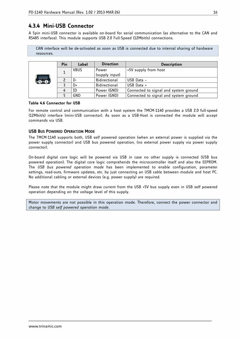
4.3.3 Motor Connector As motor connector a 4pin JST PH-series 2mm pitch single row connector is available. The motor connector is used for connecting the four motor wires of the two motor coils of the bipolar stepper motor to the electronics.
41
Pin Label Direction Description
1 OB2 Output Pin 2 of motor coil B
2 OB1 Output Pin 1 of motor coil B
3 OA2 Output Pin 2 of motor coil A
4 OA1 Output Pin 1 of motor coil A
Table 4.5 Motor connector
Example for connecting the QSH4218 NEMA 17 / 42mm stepper motors:
MA
black
green
B
blu
e
red
TMCM-1140 QS4218 Motor
Motor connector pin Cable color Coil Description
1 Red B Motor coil B pin 1
2 Blue B- Motor coil B pin 2
3 Green A- Motor coil A pin 2
4 Black A Motor coil A pin 1
PD-1140 Hardware Manual (Rev. 1.02 / 2013-MAR-26) 16
www.trinamic.com
4.3.4 Mini-USB Connector A 5pin mini-USB connector is available on-board for serial communication (as alternative to the CAN and RS485 interface). This module supports USB 2.0 Full-Speed (12Mbit/s) connections.
CAN interface will be de-activated as soon as USB is connected due to internal sharing of hardware resources.
15
Pin Label Direction Description
1 VBUS Power
(supply input) +5V supply from host
2 D- Bidirectional USB Data –
3 D+ Bidirectional USB Data +
4 ID Power (GND) Connected to signal and system ground
5 GND Power (GND) Connected to signal and system ground
Table 4.6 Connector for USB
For remote control and communication with a host system the TMCM-1140 provides a USB 2.0 full-speed (12Mbit/s) interface (mini-USB connector). As soon as a USB-Host is connected the module will accept commands via USB.
USB BUS POWERED OPERATION MODE
The TMCM-1140 supports both, USB self powered operation (when an external power is supplied via the power supply connector) and USB bus powered operation, (no external power supply via power supply connector). On-board digital core logic will be powered via USB in case no other supply is connected (USB bus powered operation). The digital core logic comprehends the microcontroller itself and also the EEPROM. The USB bus powered operation mode has been implemented to enable configuration, parameter settings, read-outs, firmware updates, etc. by just connecting an USB cable between module and host PC. No additional cabling or external devices (e.g. power supply) are required. Please note that the module might draw current from the USB +5V bus supply even in USB self powered operation depending on the voltage level of this supply.
Motor movements are not possible in this operation mode. Therefore, connect the power connector and change to USB self powered operation mode.
PD-1140 Hardware Manual (Rev. 1.02 / 2013-MAR-26) 17
www.trinamic.com
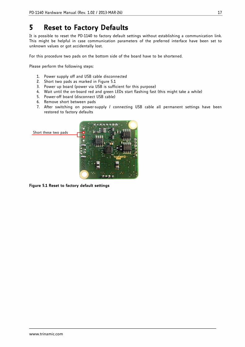
5 Reset to Factory Defaults It is possible to reset the PD-1140 to factory default settings without establishing a communication link. This might be helpful in case communication parameters of the preferred interface have been set to unknown values or got accidentally lost. For this procedure two pads on the bottom side of the board have to be shortened. Please perform the following steps:
1. Power supply off and USB cable disconnected 2. Short two pads as marked in Figure 5.1 3. Power up board (power via USB is sufficient for this purpose) 4. Wait until the on-board red and green LEDs start flashing fast (this might take a while) 5. Power-off board (disconnect USB cable) 6. Remove short between pads 7. After switching on power-supply / connecting USB cable all permanent settings have been
restored to factory defaults
Short these two pads
Figure 5.1 Reset to factory default settings
PD-1140 Hardware Manual (Rev. 1.02 / 2013-MAR-26) 18
www.trinamic.com
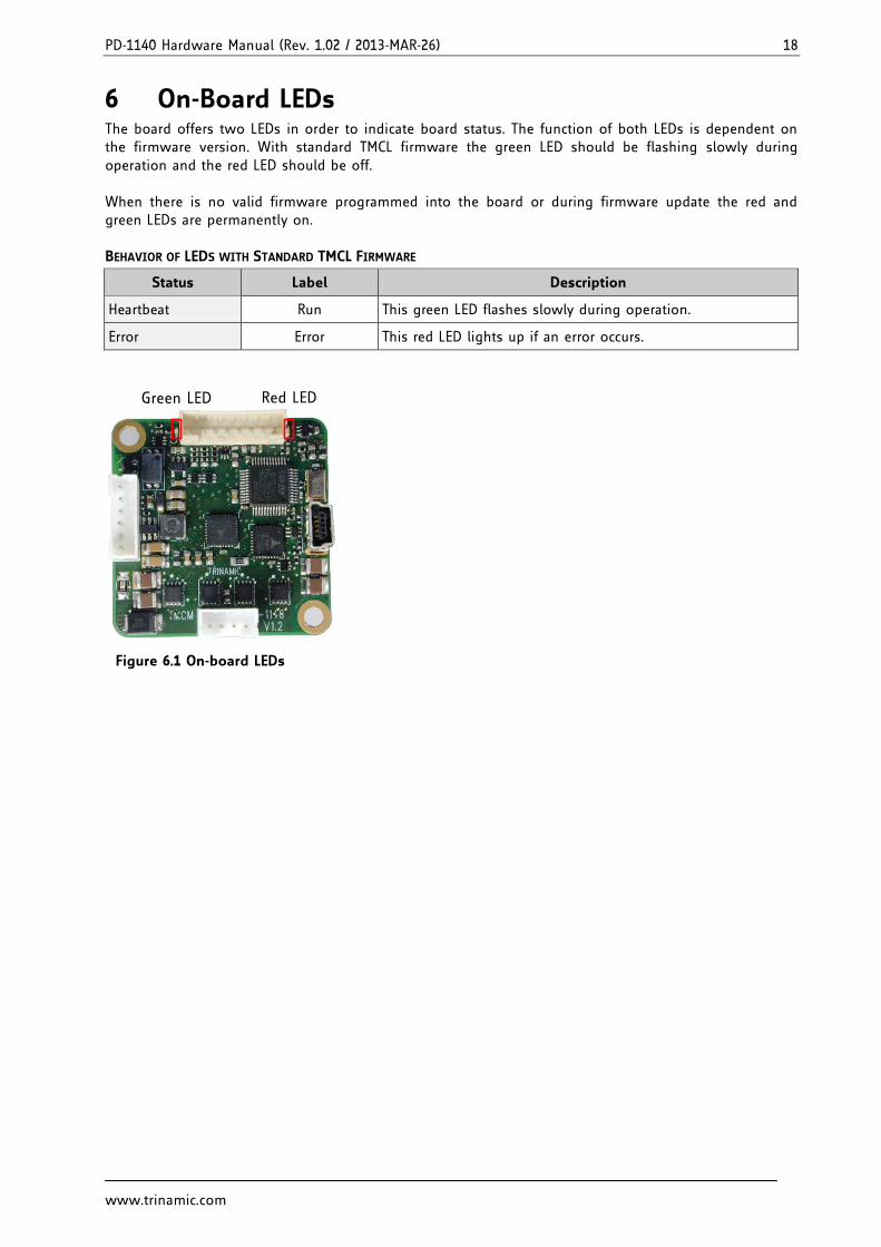
6 On-Board LEDs The board offers two LEDs in order to indicate board status. The function of both LEDs is dependent on the firmware version. With standard TMCL firmware the green LED should be flashing slowly during operation and the red LED should be off. When there is no valid firmware programmed into the board or during firmware update the red and green LEDs are permanently on. BEHAVIOR OF LEDS WITH STANDARD TMCL FIRMWARE
Status Label Description
Heartbeat Run This green LED flashes slowly during operation.
Error Error This red LED lights up if an error occurs.
Red LEDGreen LED
Figure 6.1 On-board LEDs
PD-1140 Hardware Manual (Rev. 1.02 / 2013-MAR-26) 19
www.trinamic.com
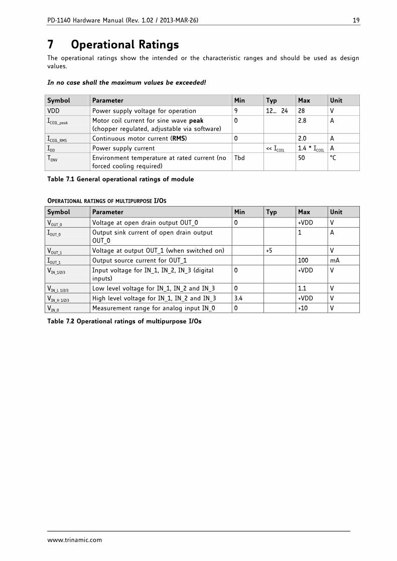
7 Operational Ratings The operational ratings show the intended or the characteristic ranges and should be used as design values. In no case shall the maximum values be exceeded!
Symbol Parameter Min Typ Max Unit
VDD Power supply voltage for operation 9 12… 24 28 V
ICOIL_peak Motor coil current for sine wave peak (chopper regulated, adjustable via software)
0 2.8 A
ICOIL_RMS Continuous motor current (RMS) 0 2.0 A
IDD Power supply current << ICOIL 1.4 * ICOIL A
TENV Environment temperature at rated current (no forced cooling required)
Tbd 50 °C
Table 7.1 General operational ratings of module
OPERATIONAL RATINGS OF MULTIPURPOSE I/OS
Symbol Parameter Min Typ Max Unit
VOUT_0 Voltage at open drain output OUT_0 0 +VDD V
IOUT_0 Output sink current of open drain output OUT_0
1 A
VOUT_1 Voltage at output OUT_1 (when switched on) +5 V
IOUT_1 Output source current for OUT_1 100 mA
VIN_1/2/3 Input voltage for IN_1, IN_2, IN_3 (digital inputs)
0 +VDD V
VIN_L 1/2/3 Low level voltage for IN_1, IN_2 and IN_3 0 1.1 V
VIN_H 1/2/3 High level voltage for IN_1, IN_2 and IN_3 3.4 +VDD V
VIN_0 Measurement range for analog input IN_0 0 +10 V
Table 7.2 Operational ratings of multipurpose I/Os
PD-1140 Hardware Manual (Rev. 1.02 / 2013-MAR-26) 20
www.trinamic.com
8 Torque Curves
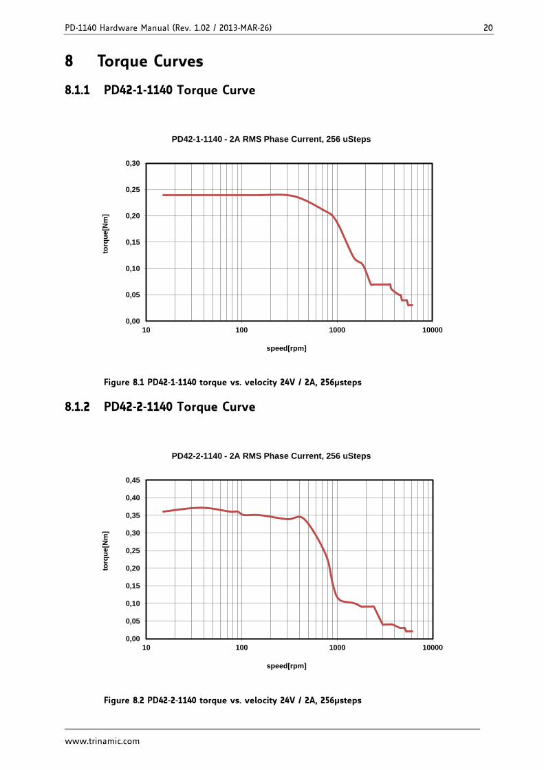
8.1.1 PD42-1-1140 Torque Curve
Figure 8.1 PD42-1-1140 torque vs. velocity 24V / 2A, 256µsteps
8.1.2 PD42-2-1140 Torque Curve
Figure 8.2 PD42-2-1140 torque vs. velocity 24V / 2A, 256µsteps
0,00
0,05
0,10
0,15
0,20
0,25
0,30
10 100 1000 10000
torq
ue
[Nm
]
speed[rpm]
PD42-1-1140 - 2A RMS Phase Current, 256 uSteps
0,00
0,05
0,10
0,15
0,20
0,25
0,30
0,35
0,40
0,45
10 100 1000 10000
torq
ue
[Nm
]
speed[rpm]
PD42-2-1140 - 2A RMS Phase Current, 256 uSteps
PD-1140 Hardware Manual (Rev. 1.02 / 2013-MAR-26) 21
www.trinamic.com
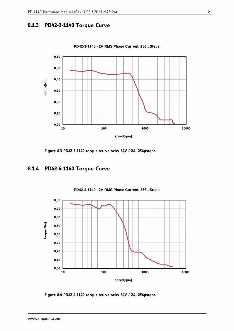
8.1.3 PD42-3-1140 Torque Curve
Figure 8.3 PD42-3-1140 torque vs. velocity 24V / 2A, 256µsteps
8.1.4 PD42-4-1140 Torque Curve
Figure 8.4 PD42-4-1140 torque vs. velocity 24V / 2A, 256µsteps
0,00
0,10
0,20
0,30
0,40
0,50
0,60
10 100 1000 10000
torq
ue
[Nm
]
speed[rpm]
PD42-3-1140 - 2A RMS Phase Current, 256 uSteps
0,00
0,10
0,20
0,30
0,40
0,50
0,60
0,70
0,80
10 100 1000 10000
torq
ue
[Nm
]
speed[rpm]
PD42-4-1140 - 2A RMS Phase Current, 256 uSteps
PD-1140 Hardware Manual (Rev. 1.02 / 2013-MAR-26) 22
www.trinamic.com
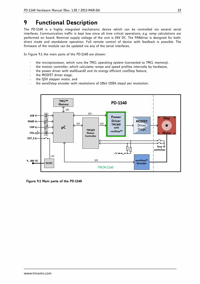
9 Functional Description The PD-1140 is a highly integrated mechatronic device which can be controlled via several serial interfaces. Communication traffic is kept low since all time critical operations, e.g. ramp calculations are performed on board. Nominal supply voltage of the unit is 24V DC. The PANdrive is designed for both: direct mode and standalone operation. Full remote control of device with feedback is possible. The firmware of the module can be updated via any of the serial interfaces. In Figure 9.1 the main parts of the PD-1140 are shown:
- the microprocessor, which runs the TMCL operating system (connected to TMCL memory), - the motion controller, which calculates ramps and speed profiles internally by hardware, - the power driver with stallGuard2 and its energy efficient coolStep feature, - the MOSFET driver stage, - the QSH stepper motor, and - the sensOstep encoder with resolutions of 10bit (1024 steps) per revolution.
9… 28V DC
µC
TMCL™Memory
5I/Os
Step
Motor
RS485 MOSFETDriverStage
SPI
PD-1140
TMCM-1140
SPIUSB
SPI
S/D
CAN
DC/DC
OUT_0
+5V
sensOstep™
EncoderSPI
TMC429Motion
Controller
Energy Efficient
DriverTMC262
Power DriverTMC262 with
coolStep™
+5V
Stop
switches
S/D
Figure 9.1 Main parts of the PD-1140
PD-1140 Hardware Manual (Rev. 1.02 / 2013-MAR-26) 23
www.trinamic.com
10 PD-1140 Operational Description
10.1 Calculation: Velocity and Acceleration vs. Microstep and Fullstep Frequency
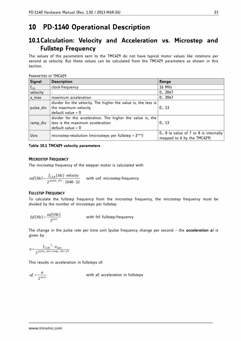
The values of the parameters sent to the TMC429 do not have typical motor values like rotations per second as velocity. But these values can be calculated from the TMC429 parameters as shown in this section. PARAMETERS OF TMC429
Signal Description Range
fCLK clock-frequency 16 MHz
velocity - 0… 2047
a_max maximum acceleration 0… 2047
pulse_div divider for the velocity. The higher the value is, the less is the maximum velocity default value = 0
0… 13
ramp_div divider for the acceleration. The higher the value is, the less is the maximum acceleration default value = 0
0… 13
Usrs microstep-resolution (microsteps per fullstep = 2usrs) 0… 8 (a value of 7 or 8 is internally mapped to 6 by the TMC429)
Table 10.1 TMC429 velocity parameters
MICROSTEP FREQUENCY
The microstep frequency of the stepper motor is calculated with
3220482
][][
_
divpulse
CLK velocityHzfHzusf with usf: microstep-frequency
FULLSTEP FREQUENCY
To calculate the fullstep frequency from the microstep frequency, the microstep frequency must be divided by the number of microsteps per fullstep.
usrs
HzusfHzfsf
2
][][ with fsf: fullstep-frequency
The change in the pulse rate per time unit (pulse frequency change per second – the acceleration a) is given by
29__
max2
2
divrampdivpulse
CLK afa
This results in acceleration in fullsteps of:
usrs
aaf
2 with af: acceleration in fullsteps
PD-1140 Hardware Manual (Rev. 1.02 / 2013-MAR-26) 24
www.trinamic.com
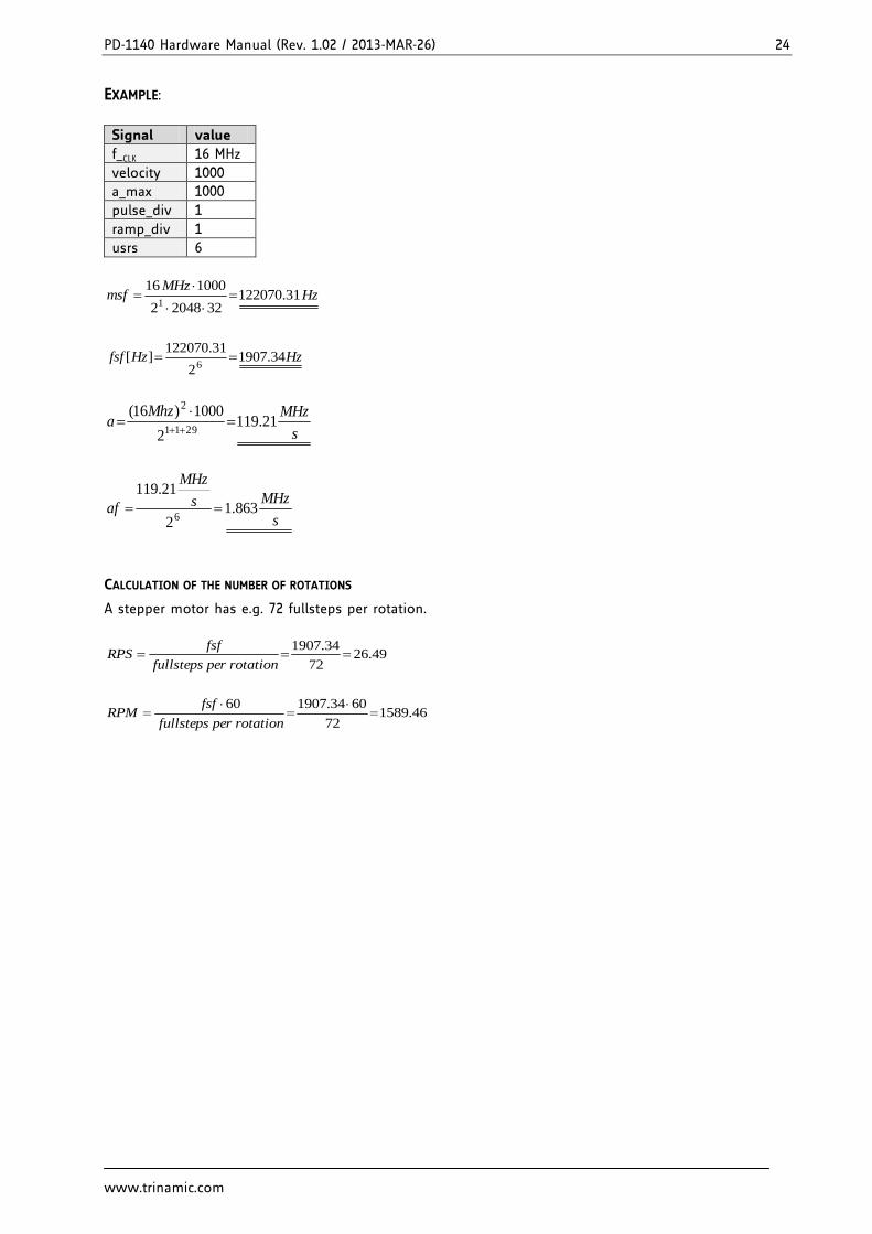
EXAMPLE:
Signal value
f_CLK 16 MHz
velocity 1000
a_max 1000
pulse_div 1
ramp_div 1
usrs 6
HzMHz
msf 31.1220703220482
1000161
HzHzfsf 34.19072
31.122070][
6
s
MHzMhza 21.119
2
1000)16(2911
2
s
MHzs
MHz
af 863.12
21.119
6
CALCULATION OF THE NUMBER OF ROTATIONS
A stepper motor has e.g. 72 fullsteps per rotation.
49.2672
34.1907
rotationperfullsteps
fsfRPS
46.158972
6034.190760
rotationperfullsteps
fsfRPM
PD-1140 Hardware Manual (Rev. 1.02 / 2013-MAR-26) 25
www.trinamic.com
11 Life Support Policy TRINAMIC Motion Control GmbH & Co. KG does not authorize or warrant any of its products for use in life support systems, without the specific written consent of TRINAMIC Motion Control GmbH & Co. KG. Life support systems are equipment intended to support or sustain life, and whose failure to perform, when properly used in accordance with instructions provided, can be reasonably expected to result in personal injury or death. © TRINAMIC Motion Control GmbH & Co. KG 2013 Information given in this data sheet is believed to be accurate and reliable. However neither responsibility is assumed for the consequences of its use nor for any infringement of patents or other rights of third parties, which may result from its use. Specifications are subject to change without notice. All trademarks used are property of their respective owners.
PD-1140 Hardware Manual (Rev. 1.02 / 2013-MAR-26) 26
www.trinamic.com
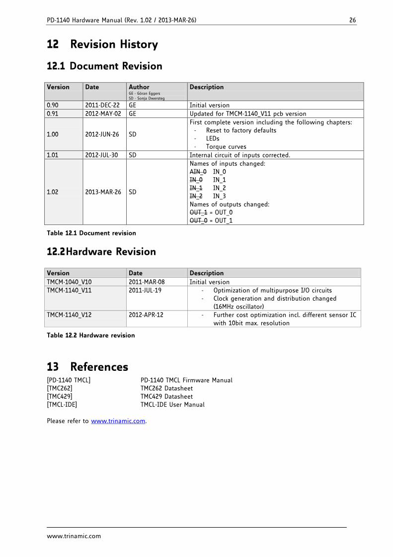
12 Revision History
12.1 Document Revision
Version Date Author GE - Göran Eggers SD - Sonja Dwersteg
Description
0.90 2011-DEC-22 GE Initial version
0.91 2012-MAY-02 GE Updated for TMCM-1140_V11 pcb version
1.00 2012-JUN-26 SD
First complete version including the following chapters: - Reset to factory defaults - LEDs - Torque curves
1.01 2012-JUL-30 SD Internal circuit of inputs corrected.
1.02 2013-MAR-26 SD
Names of inputs changed: AIN_0 IN_0 IN_0 IN_1 IN_1 IN_2 IN_2 IN_3 Names of outputs changed: OUT_1 = OUT_0 OUT_0 = OUT_1
Table 12.1 Document revision
12.2 Hardware Revision
Version Date Description
TMCM-1040_V10 2011-MAR-08 Initial version
TMCM-1140_V11 2011-JUL-19 - Optimization of multipurpose I/O circuits - Clock generation and distribution changed
(16MHz oscillator)
TMCM-1140_V12 2012-APR-12 - Further cost optimization incl. different sensor IC with 10bit max. resolution
Table 12.2 Hardware revision
13 References [PD-1140 TMCL] PD-1140 TMCL Firmware Manual [TMC262] TMC262 Datasheet [TMC429] TMC429 Datasheet [TMCL-IDE] TMCL-IDE User Manual Please refer to www.trinamic.com.