Embed Size (px)
Citation preview
0900381 Rev: G (10/12) Page 1 of 12
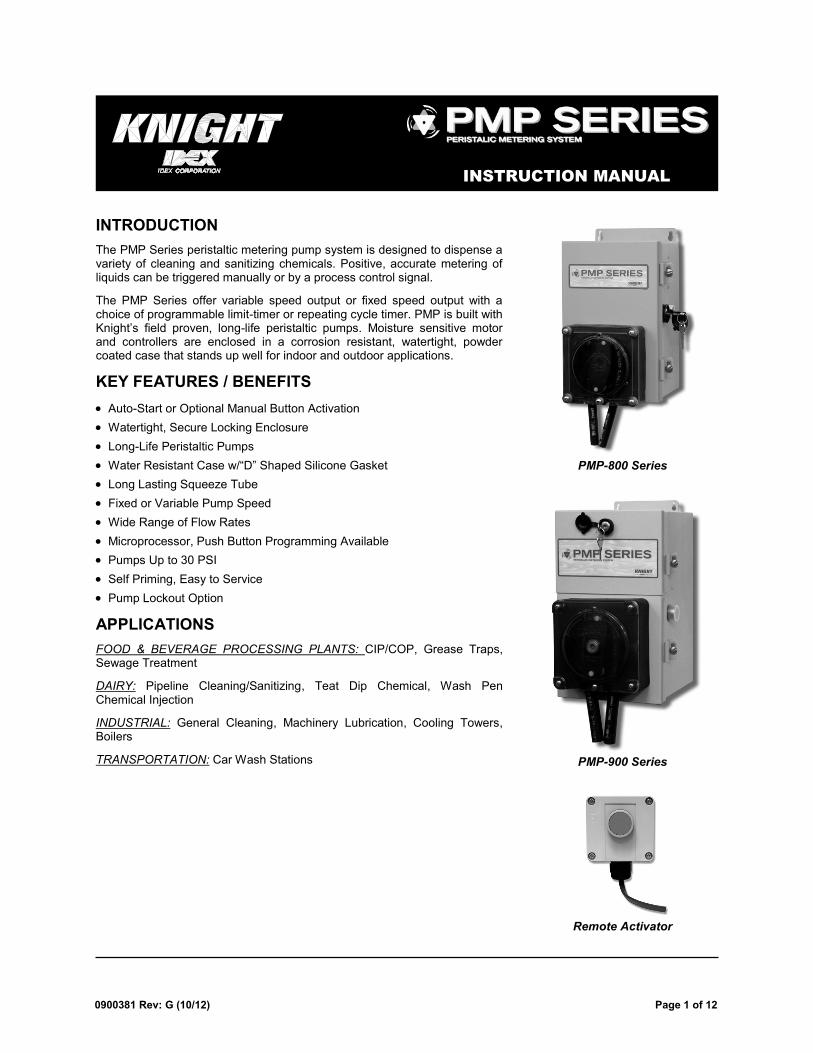
INSTRUCTION MANUAL
INTRODUCTION
The PMP Series peristaltic metering pump system is designed to dispense a variety of cleaning and sanitizing chemicals. Positive, accurate metering of liquids can be triggered manually or by a process control signal.
The PMP Series offer variable speed output or fixed speed output with a choice of programmable limit-timer or repeating cycle timer. PMP is built with Knight’s field proven, long-life peristaltic pumps. Moisture sensitive motor and controllers are enclosed in a corrosion resistant, watertight, powder coated case that stands up well for indoor and outdoor applications.
KEY FEATURES / BENEFITS
Auto-Start or Optional Manual Button Activation
Watertight, Secure Locking Enclosure
Long-Life Peristaltic Pumps
Water Resistant Case w/―D‖ Shaped Silicone Gasket
Long Lasting Squeeze Tube
Fixed or Variable Pump Speed
Wide Range of Flow Rates
Microprocessor, Push Button Programming Available
Pumps Up to 30 PSI
Self Priming, Easy to Service
Pump Lockout Option
APPLICATIONS
FOOD & BEVERAGE PROCESSING PLANTS: CIP/COP, Grease Traps, Sewage Treatment
DAIRY: Pipeline Cleaning/Sanitizing, Teat Dip Chemical, Wash Pen Chemical Injection
INDUSTRIAL: General Cleaning, Machinery Lubrication, Cooling Towers, Boilers
TRANSPORTATION: Car Wash Stations
PMP-800 Series
PMP-900 Series
Remote Activator
Page 2 of 12 0900381 Rev: G (10/12)
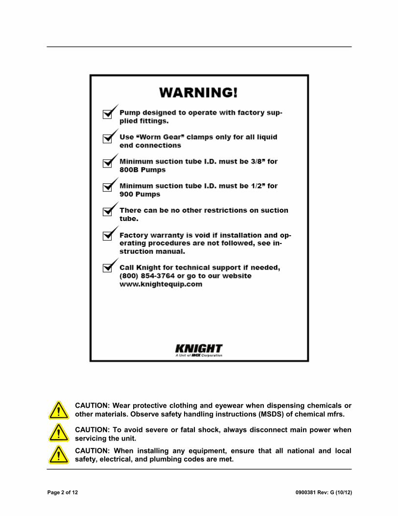
CAUTION: Wear protective clothing and eyewear when dispensing chemicals or
other materials. Observe safety handling instructions (MSDS) of chemical mfrs.
CAUTION: To avoid severe or fatal shock, always disconnect main power when
servicing the unit.
CAUTION: When installing any equipment, ensure that all national and local safety, electrical, and plumbing codes are met.
0900381 Rev: G (10/12) Page 3 of 12
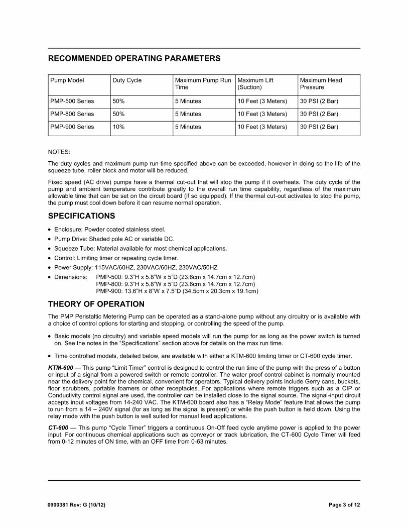
Pump Model Duty Cycle Maximum Pump Run Time
Maximum Lift (Suction)
Maximum Head Pressure
PMP-500 Series 50% 5 Minutes 10 Feet (3 Meters) 30 PSI (2 Bar)
PMP-800 Series 50% 5 Minutes 10 Feet (3 Meters) 30 PSI (2 Bar)
PMP-900 Series 10% 5 Minutes 10 Feet (3 Meters) 30 PSI (2 Bar)
RECOMMENDED OPERATING PARAMETERS
NOTES:
The duty cycles and maximum pump run time specified above can be exceeded, however in doing so the life of the squeeze tube, roller block and motor will be reduced.
Fixed speed (AC drive) pumps have a thermal cut-out that will stop the pump if it overheats. The duty cycle of the pump and ambient temperature contribute greatly to the overall run time capability, regardless of the maximum allowable time that can be set on the circuit board (if so equipped). If the thermal cut-out activates to stop the pump, the pump must cool down before it can resume normal operation.
SPECIFICATIONS
Enclosure: Powder coated stainless steel.
Pump Drive: Shaded pole AC or variable DC.
Squeeze Tube: Material available for most chemical applications.
Control: Limiting timer or repeating cycle timer.
Power Supply: 115VAC/60HZ, 230VAC/60HZ, 230VAC/50HZ
Dimensions: PMP-500: 9.3‖H x 5.8‖W x 5‖D (23.6cm x 14.7cm x 12.7cm)
PMP-800: 9.3‖H x 5.8‖W x 5‖D (23.6cm x 14.7cm x 12.7cm) PMP-900: 13.6‖H x 8‖W x 7.5‖D (34.5cm x 20.3cm x 19.1cm)
THEORY OF OPERATION
The PMP Peristaltic Metering Pump can be operated as a stand-alone pump without any circuitry or is available with a choice of control options for starting and stopping, or controlling the speed of the pump.
Basic models (no circuitry) and variable speed models will run the pump for as long as the power switch is turned
on. See the notes in the ―Specifications‖ section above for details on the max run time.
Time controlled models, detailed below, are available with either a KTM-600 limiting timer or CT-600 cycle timer.
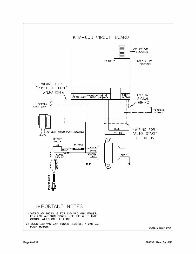
KTM-600 — This pump ―Limit Timer‖ control is designed to control the run time of the pump with the press of a button or input of a signal from a powered switch or remote controller. The water proof control cabinet is normally mounted near the delivery point for the chemical, convenient for operators. Typical delivery points include Gerry cans, buckets, floor scrubbers, portable foamers or other receptacles. For applications where remote triggers such as a CIP or Conductivity control signal are used, the controller can be installed close to the signal source. The signal-input circuit accepts input voltages from 14-240 VAC. The KTM-600 board also has a ―Relay Mode‖ feature that allows the pump to run from a 14 – 240V signal (for as long as the signal is present) or while the push button is held down. Using the relay mode with the push button is well suited for manual feed applications.
CT-600 — This pump ―Cycle Timer‖ triggers a continuous On-Off feed cycle anytime power is applied to the power input. For continuous chemical applications such as conveyor or track lubrication, the CT-600 Cycle Timer will feed from 0-12 minutes of ON time, with an OFF time from 0-63 minutes.
Page 4 of 12 0900381 Rev: G (10/12)
INSTALLATION
(1) Check voltage of installation with a voltmeter and compare with voltage inputs of pump unit before mounting. Application of incorrect voltage will permanently damage unit and is not covered under warranty.
(2) Mount unit on wall or shelf in a convenient location near both injection point and chemical supply. Do not mount unit in direct path of steam. This can short circuit and permanently damage your system.
(3) Install power leads. Most systems include a power cord for easy connection. Variable speed systems have an internal transformer which steps down the incoming voltage. Rigid or flexible conduit should be used to ensure safety and continued operation without shorts. The green ground wire must be applied to ground. Failure to do so will void warranty.
(4) 500 Series: Install poly tubing between the discharge (right) tube side of the peristaltic pump and the injection point. Use tie wraps to secure flow tubing to squeeze tube. Bulkhead fittings and in-line injection fittings can be provided for various installations. 800/900 Series: Install braided tubing between the discharge (right) tube side of the peristaltic pump and the injection point. Use the provided stainless steel hose clamps and barb fittings to secure braided tubing to squeeze tube.
(5) 500 Series: Install poly tubing between the suction (left) tube side and the PVC product pickup tube provided. Use tie wraps to secure flow tubing to squeeze tube. Be sure to draw the tubing through the end of the pickup tube. 800/900 Series: Install braided tubing between the suction (left) tube side and the barb fitting on the PVC pickup tube provided. Use the provided stainless steel hose clamps and barb fittings to secure braided tubing to squeeze tube.
(6) Some units are equipped with an optional prime switch which can be used to fill the suction and discharge tubing connected to the pump. Depending on the model, the pump will either run as long as the prime switch is depressed, or will trigger a timed injection set on the control circuit board (if so equipped).
MAINTENANCE
The PMP Series of Metering Pumps require a minimal amount of maintenance to achieve optimal performance. Periodically check the squeeze tube for cracks, deterioration, or swelling. The squeeze tube will typically need to be replaced about every 6 months (chemical compatibility and duty cycle can cause this interval to vary).
Applying lube to the squeeze tube once a month will extend the life of the tube, minimize wear on other contacting parts, and promote smoother pump operation. Use Knight Tube Lube (P/N 7506621) or an equivalent silicone-based lubricant.
(1) Remove the faceplate of the pump.
(2) Apply a thin bead of Tube Lube to the inner surface (the side that the rollers contact) of the squeeze tube between the 9 o’clock and 3 o’clock positions. Avoid getting lube near the pinch points where the bottom of the faceplate grips the tube.
(3) Put the faceplate back on the pump.
(4) Activate the pump under normal operation — the lubricant will be evenly distributed as the pump rotates.
0900381 Rev: G (10/12) Page 5 of 12
MODELS WITH KTM-600
Pump Run Time: (max run time is 12 minutes and 42 seconds)
(1) Locate the dip-switch pack on the circuit board — set switch #6 to SIGNAL, set switch #7 to RUN TIME and set switch #8 to PROGRAM MODE.
(2) Using a measuring cup or beaker, press Start switch and release when pump starts. Let the pump run until desired amount of chemical is dispensed then press Start switch again to stop. The run time is now programmed. Repeat step if new volume is required.
(3) Set mode switch #8 to RUN MODE.
Delay Time: (max delay time is 12 minutes and 42 seconds)
(1) Locate the dip-switch pack on the circuit board — set switch #6 to SIGNAL, set switch #7 to DELAY TIME and set switch #8 to PROGRAM MODE.
(2) Press Start switch and release when the LED begins flashing. When the desired delay time has passed, press the Start switch again. The delay time is now programmed. Repeat step if new delay time is required.
(3) Set mode switch #8 to RUN MODE.
Lock-Out Time: (max lock-out time is 31 minutes)
This feature defeats consecutive dispensing of product for a pre-determined interval. Select a combination of switches 1 – 5 to program total lock-out time. Example: For 10 minute lock-out, set switches #2 and #4 to ON with all other switches OFF. For maximum lock-out (31 min) set all switches ON. For no lock-out, set all switches OFF.
OPERATION
Manual activation: Press the Start button for 1 full second. The unit will begin counting down the delay time (if used) and will then run the pump for the amount of time programmed. Once the lock-out time expires (if used) the pump will be ready to restart.
Signal activation: When the signal input on the circuit board receives a 14-240VAC trigger signal for at least 5 seconds, the delay time (if used) will begin counting down. Then the pump will run for the amount of time programmed. Once the lock-out time expires (if used) the pump will be ready to restart.
Relay Mode: Set switch #6 to RELAY. The pump will activate for as long as an external trigger signal is present, or for as long as the manual button is depressed. All other board functions (such as delay time and lock-out time) are by-passed in relay mode.
DISABLING THE START BUTTON
There is a jumper marked ―JP1‖ on the circuit board that can be used to prevent manual activation in certain applications, or to allow manual activation by remote push-button only. This jumper only affects the on-board start button. A remote start button, or trigger signal, can always be used to activate the pump.
When the jumper is ON, the on-board start button is functional.
When the jumper OFF, the on-board start button is disabled.
PRIMING
(1) Locate the dip-switch pack on the circuit board and set switch #6 to RELAY.
(2) Press and hold the Start button until the chemical line is fully primed, then release the button.
(3) Set switch #6 to SIGNAL (unless you intend to use relay mode).
Page 6 of 12 0900381 Rev: G (10/12)
0900381 Rev: G (10/12) Page 7 of 12
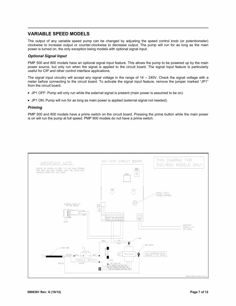
VARIABLE SPEED MODELS
The output of any variable speed pump can be changed by adjusting the speed control knob (or potentiometer) clockwise to increase output or counter-clockwise to decrease output. The pump will run for as long as the main power is turned on, the only exception being models with optional signal input.
Optional Signal Input
PMP 500 and 800 models have an optional signal input feature. This allows the pump to be powered up by the main power source, but only run when the signal is applied to the circuit board. The signal input feature is particularly useful for CIP and other control interface applications.
The signal input circuitry will accept any signal voltage in the range of 14 – 240V. Check the signal voltage with a meter before connecting to the circuit board. To activate the signal input feature, remove the jumper marked ―JP1‖ from the circuit board.
JP1 OFF: Pump will only run while the external signal is present (main power is assumed to be on).
JP1 ON: Pump will run for as long as main power is applied (external signal not needed).
Priming
PMP 500 and 800 models have a prime switch on the circuit board. Pressing the prime button while the main power is on will run the pump at full speed. PMP 900 models do not have a prime switch.
Page 8 of 12 0900381 Rev: G (10/12)
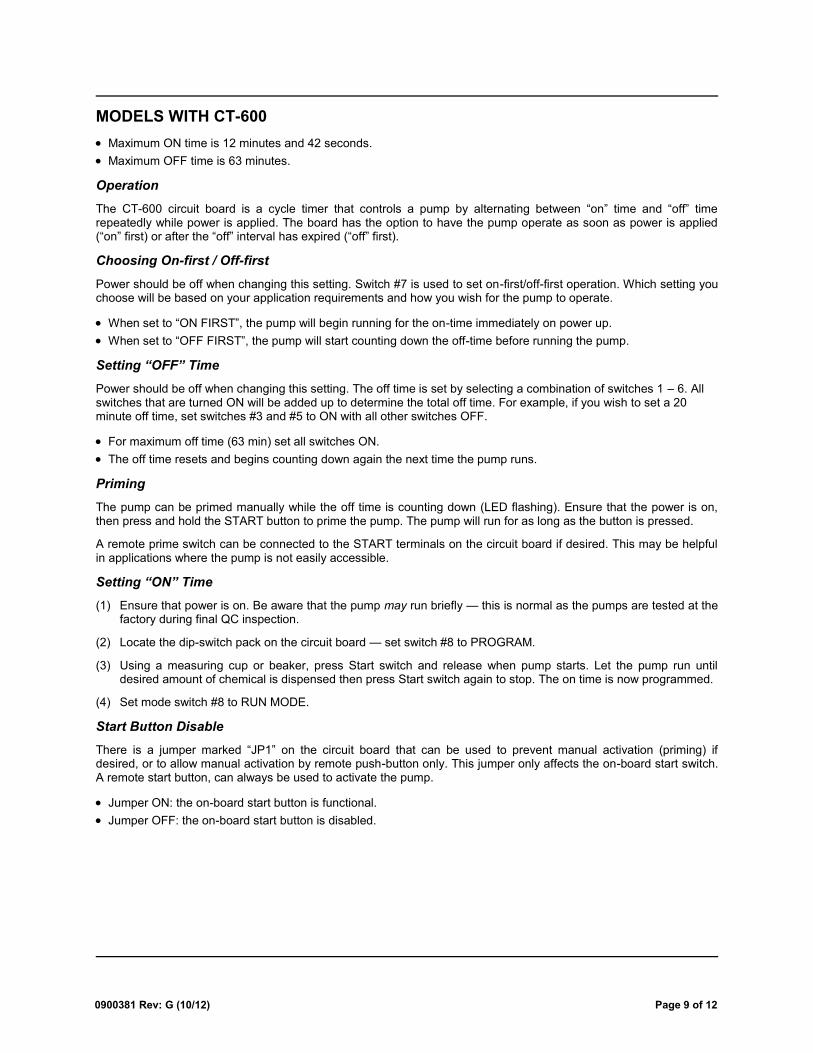
0900381 Rev: G (10/12) Page 9 of 12
MODELS WITH CT-600
Maximum ON time is 12 minutes and 42 seconds.
Maximum OFF time is 63 minutes.
Operation
The CT-600 circuit board is a cycle timer that controls a pump by alternating between ―on‖ time and ―off‖ time repeatedly while power is applied. The board has the option to have the pump operate as soon as power is applied (―on‖ first) or after the ―off‖ interval has expired (―off‖ first).
Choosing On-first / Off-first
Power should be off when changing this setting. Switch #7 is used to set on-first/off-first operation. Which setting you choose will be based on your application requirements and how you wish for the pump to operate.
When set to ―ON FIRST‖, the pump will begin running for the on-time immediately on power up.
When set to ―OFF FIRST‖, the pump will start counting down the off-time before running the pump.
Setting “OFF” Time
Power should be off when changing this setting. The off time is set by selecting a combination of switches 1 – 6. All switches that are turned ON will be added up to determine the total off time. For example, if you wish to set a 20 minute off time, set switches #3 and #5 to ON with all other switches OFF.
For maximum off time (63 min) set all switches ON.
The off time resets and begins counting down again the next time the pump runs.
Priming
The pump can be primed manually while the off time is counting down (LED flashing). Ensure that the power is on, then press and hold the START button to prime the pump. The pump will run for as long as the button is pressed.
A remote prime switch can be connected to the START terminals on the circuit board if desired. This may be helpful in applications where the pump is not easily accessible.
Setting “ON” Time
(1) Ensure that power is on. Be aware that the pump may run briefly — this is normal as the pumps are tested at the factory during final QC inspection.
(2) Locate the dip-switch pack on the circuit board — set switch #8 to PROGRAM.
(3) Using a measuring cup or beaker, press Start switch and release when pump starts. Let the pump run until desired amount of chemical is dispensed then press Start switch again to stop. The on time is now programmed.
(4) Set mode switch #8 to RUN MODE.
Start Button Disable
There is a jumper marked ―JP1‖ on the circuit board that can be used to prevent manual activation (priming) if desired, or to allow manual activation by remote push-button only. This jumper only affects the on-board start switch. A remote start button, can always be used to activate the pump.
Jumper ON: the on-board start button is functional.
Jumper OFF: the on-board start button is disabled.
Page 10 of 12 0900381 Rev: G (10/12)
0900381 Rev: G (10/12) Page 11 of 12
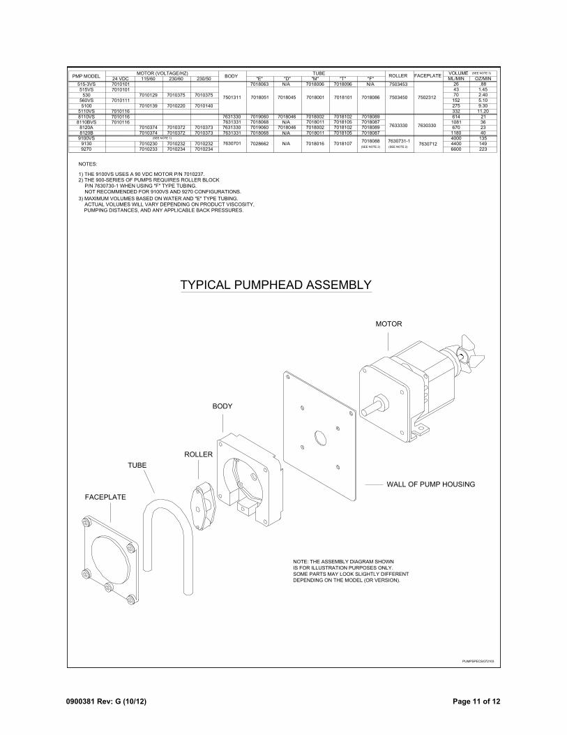
TUBE
ROLLER
FACEPLATE
BODY
MOTOR
91309100VS8120B8120A
8110VS
5110VS5100
560VS530
515VS515-3VS
7010129
7010139
70103747010374
70102307010233 7010234
7010232
70103727010372
7010220
7010375
7630701
7631331
7631330
7501311
7028662
7018068
7019060
7018051
7018016
7018011
7018002
7018001
7018107
7018105
7018102
7018101
7018088
7018087
7018089
7018086
7630731-1
7633330
7503450
7630712
7630330
7502312
115/60 230/60 230/50 "E" "M" "T" "F"
9270
N/A
BODY ROLLER FACEPLATEMOTOR (VOLTAGE/HZ) TUBE
701010124 VDC
7010101
7010116
7010116
7010111
7018063 7018006 7018096 7503453
PMP MODELVOLUME
6600440040001180670
614
332275152704326
ML/MIN OZ/MIN.88
1.452.405.109.30
11.20
21
2340
135149223
NOTES:
1) THE 9100VS USES A 90 VDC MOTOR P/N 7010237.2) THE 900-SERIES OF PUMPS REQUIRES ROLLER BLOCK
P/N 7630730-1 WHEN USING "F" TYPE TUBING.
7010375
7010140
70103737010373
70102327010234
(SEE NOTE 1)
(SEE NOTE 2) (SEE NOTE 2)
3) MAXIMUM VOLUMES BASED ON WATER AND "E" TYPE TUBING. ACTUAL VOLUMES WILL VARY DEPENDING ON PRODUCT VISCOSITY, PUMPING DISTANCES, AND ANY APPLICABLE BACK PRESSURES.
WALL OF PUMP HOUSING
NOT RECOMMENDED FOR 9100VS AND 9270 CONFIGURATIONS.
PUMPSPECS/072103
7631330 7019060 7018002 7018102 70180898110BVS 7010116 1081 367631331 7018068 7018011 7018105 7018087
"D"N/A
7018045
7018046
7018046N/A
N/A
N/A
(SEE NOTE 3)
TYPICAL PUMPHEAD ASSEMBLY
IS FOR ILLUSTRATION PURPOSES ONLY.
NOTE: THE ASSEMBLY DIAGRAM SHOWN
SOME PARTS MAY LOOK SLIGHTLY DIFFERENT
DEPENDING ON THE MODEL (OR VERSION).
Page 12 of 12 0900381 Rev: G (10/12)
DISCLAIMER
Knight LLC does not accept responsibility for the mishandling, misuse, or non-performance of the described items when used for purposes other than those specified in the instructions. For hazardous materials information consult label, MSDS, or Knight LLC. Knight products are not for use in potentially explosive environments. Any use of our equipment in such an environment is at the risk of the user, Knight does not accept any liability in such circumstances.
WARRANTY
All Knight controls and pump systems are warranted against defects in material and workmanship for a period of ONE year. All electronic control boards have a TWO year warranty. Warranty applies only to the replacement or repair of such parts when returned to factory with a Knight Return Authorization (KRA) number, freight prepaid, and found to be defective upon factory authorized inspection. Bearings and pump seals or rubber and synthetic rubber parts such as ―O‖ rings, diaphragms, squeeze tubing, and gaskets are considered expendable and are not covered under warranty. Warranty does not cover liability resulting from performance of this equipment nor the labor to replace this equipment. Product abuse or misuse voids warranty.
World Headquarters 20531 Crescent Bay Drive
Lake Forest, CA 92630 Tel: 949.595.4800 Fax: 949.595.4801
www.knightequip.com
USA Toll Free Tel: 800.854.3764 Fax: 800.752.9518
Canada
Tel: 905.542.2333 Fax: 905.542.1536
Australia Tel: 61.2.9725.2588 Fax: 61.2.9725.2025
UK
Tel: 44.1293.615.570 Fax: 44.1293.615.585
North Europe Tel: 31.53.428.5800 Fax: 31.53.428.5809
South Europe
Tel: 34.93.487.1015 Fax: 34.93.215.2019
North Asia Pacific Tel: 82.2.3481.6683 Fax: 82.2.3482.5742
Southeast Asia
Tel: 65.9170.0984 Fax: 65.6489.6723
KNIGHT LLC, A Unit of IDEX Corporation