Embed Size (px)
Citation preview
February 2021
By Hitachi Vantara
Implementation Guide
Hitachi Solution for Databases - Oracle Real Application Clusters Database 19c with Hitachi Advanced Server DS220 and Global-active Device using Virtual Storage Platform E990 and Hitachi Ops Center Protector

Feedback
Hitachi Vantara welcomes your feedback. Please share your thoughts by sending an email message to [email protected]. To assist the routing of this message, use the paper number in the subject and the title of this white paper in the text.
Revision History
Revision Changes Date
MK-SL-218-00 Initial release February 9, 2021
Table of ContentsIntroduction 2
Tested Solution Components 3Server and Application Architecture 13
SAN Architecture 14
Network Architecture 17
Global-active Device Setup Pre-configuration 20
Solution Implementation 21Solution Tests 27

1
1
Hitachi Solution for Databases - Oracle Real Application Clusters Database 19c with Hitachi Advanced Server DS220 and Global-active Device using Virtual Storage Platform E990 and Hitachi Ops Center ProtectorImplementation Guide
Use this implementation guide to design a solution with Hitachi Ops Center Protector to protect Hitachi Solution for Databases for Oracle Real Application Clusters (Oracle RAC). This solution is for Oracle RAC on Extended Distance Clusters (stretched) in a two-site environment using global-active device in Hitachi Virtual Storage Platform.
This guide explains the following:
How to use Hitachi Ops Center Protector to deploy global-active device to add backup and recovery capabilities in an Oracle environment to achieve zero recovery point objective (RPO) and recovery time objective (RTO).
How to use global-active device without using an external storage system for quorum configuration in a two-site replication environment with Virtual Storage Platform E990 series to provide data protection for Oracle Database.
How to use Hitachi Ops Center Protector to perform automated two-datacenter swap global-active device replication on demand and automated recovery of global-active device replication in an error or suspended state.
How Hitachi Ops Center Protector integrates with Oracle RMAN using the SBT interface. The practices in this guide are valid for all storage systems that support global-active device and are not limited to the storage environment used to validate this implementation.
This guide is written for IT professionals charged with the following roles:
Database administrator
Storage administrator
Database performance analyzer
IT professional with the responsibility of planning and deploying an Oracle Database solution
2
2
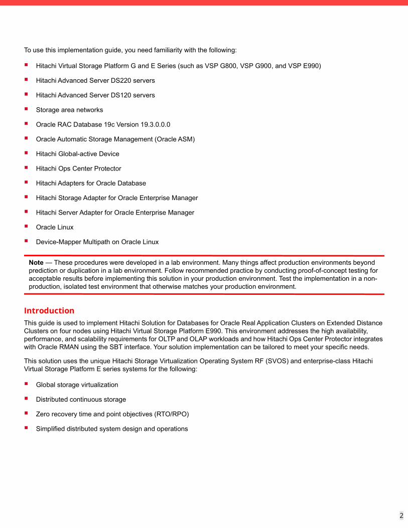
To use this implementation guide, you need familiarity with the following:
Hitachi Virtual Storage Platform G and E Series (such as VSP G800, VSP G900, and VSP E990)
Hitachi Advanced Server DS220 servers
Hitachi Advanced Server DS120 servers
Storage area networks
Oracle RAC Database 19c Version 19.3.0.0.0
Oracle Automatic Storage Management (Oracle ASM)
Hitachi Global-active Device
Hitachi Ops Center Protector
Hitachi Adapters for Oracle Database
Hitachi Storage Adapter for Oracle Enterprise Manager
Hitachi Server Adapter for Oracle Enterprise Manager
Oracle Linux
Device-Mapper Multipath on Oracle Linux
Note — These procedures were developed in a lab environment. Many things affect production environments beyond prediction or duplication in a lab environment. Follow recommended practice by conducting proof-of-concept testing for acceptable results before implementing this solution in your production environment. Test the implementation in a non- production, isolated test environment that otherwise matches your production environment.
IntroductionThis guide is used to implement Hitachi Solution for Databases for Oracle Real Application Clusters on Extended Distance Clusters on four nodes using Hitachi Virtual Storage Platform E990. This environment addresses the high availability, performance, and scalability requirements for OLTP and OLAP workloads and how Hitachi Ops Center Protector integrates with Oracle RMAN using the SBT interface. Your solution implementation can be tailored to meet your specific needs.
This solution uses the unique Hitachi Storage Virtualization Operating System RF (SVOS) and enterprise-class Hitachi Virtual Storage Platform E series systems for the following:
Global storage virtualization
Distributed continuous storage
Zero recovery time and point objectives (RTO/RPO)
Simplified distributed system design and operations
3
3
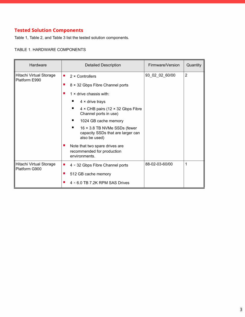
Tested Solution ComponentsTable 1, Table 2, and Table 3 list the tested solution components.
TABLE 1. HARDWARE COMPONENTS
Hardware Detailed Description Firmware/Version Quantity
Hitachi Virtual Storage Platform E990
2 × Controllers
8 × 32 Gbps Fibre Channel ports
1 × drive chassis with:
4 × drive trays
4 × CHB pairs (12 × 32 Gbps Fibre Channel ports in use)
1024 GB cache memory
16 × 3.8 TB NVMe SSDs (fewer capacity SSDs that are larger can also be used)
Note that two spare drives are recommended for production environments.
93_02_02_60/00 2
Hitachi Virtual Storage Platform G900
4 × 32 Gbps Fibre Channel ports
512 GB cache memory
4 × 6.0 TB 7.2K RPM SAS Drives
88-02-03-60/00 1
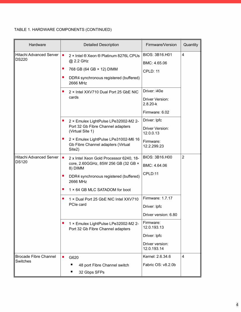
4
4
Hitachi Advanced Server DS220
2 × Intel ® Xeon ® Platinum 8276L CPUs @ 2.2 GHz
768 GB (64 GB × 12) DIMM
DDR4 synchronous registered (buffered) 2666 MHz
BIOS: 3B16.H01
BMC: 4.65.06
CPLD: 11
4
2 × Intel XXV710 Dual Port 25 GbE NIC cards
Driver: i40e
Driver Version: 2.8.20-k
Firmware: 6.02
2 × Emulex LightPulse LPe32002-M2 2-Port 32 Gb Fibre Channel adapters (Virtual Site 1)
2 × Emulex LightPulse LPe31002-M6 16 Gb Fibre Channel adapters (Virtual Site2)
Driver: lpfc
Driver Version: 12.0.0.13
Firmware: 12.2.299.23
Hitachi Advanced Server DS120
2 x Intel Xeon Gold Processor 6240, 18-core, 2.60GGHz, 85W 256 GB (32 GB × 8) DIMM
DDR4 synchronous registered (buffered) 2666 MHz
1 × 64 GB MLC SATADOM for boot
BIOS: 3B16.H00
BMC: 4.64.06
CPLD:11
2
1 × Dual Port 25 GbE NIC Intel XXV710 PCIe card
Firmware: 1.7.17
Driver: lpfc
Driver version: 6.80
1 × Emulex LightPulse LPe32002-M2 2-Port 32 Gb Fibre Channel adapters
Firmware: 12.0.193.13
Driver: lpfc
Driver version: 12.0.193.14
Brocade Fibre Channel Switches
G620
48 port Fibre Channel switch
32 Gbps SFPs
Kernel: 2.6.34.6
Fabric OS: v8.2.0b
4
TABLE 1. HARDWARE COMPONENTS (CONTINUED)
Hardware Detailed Description Firmware/Version Quantity
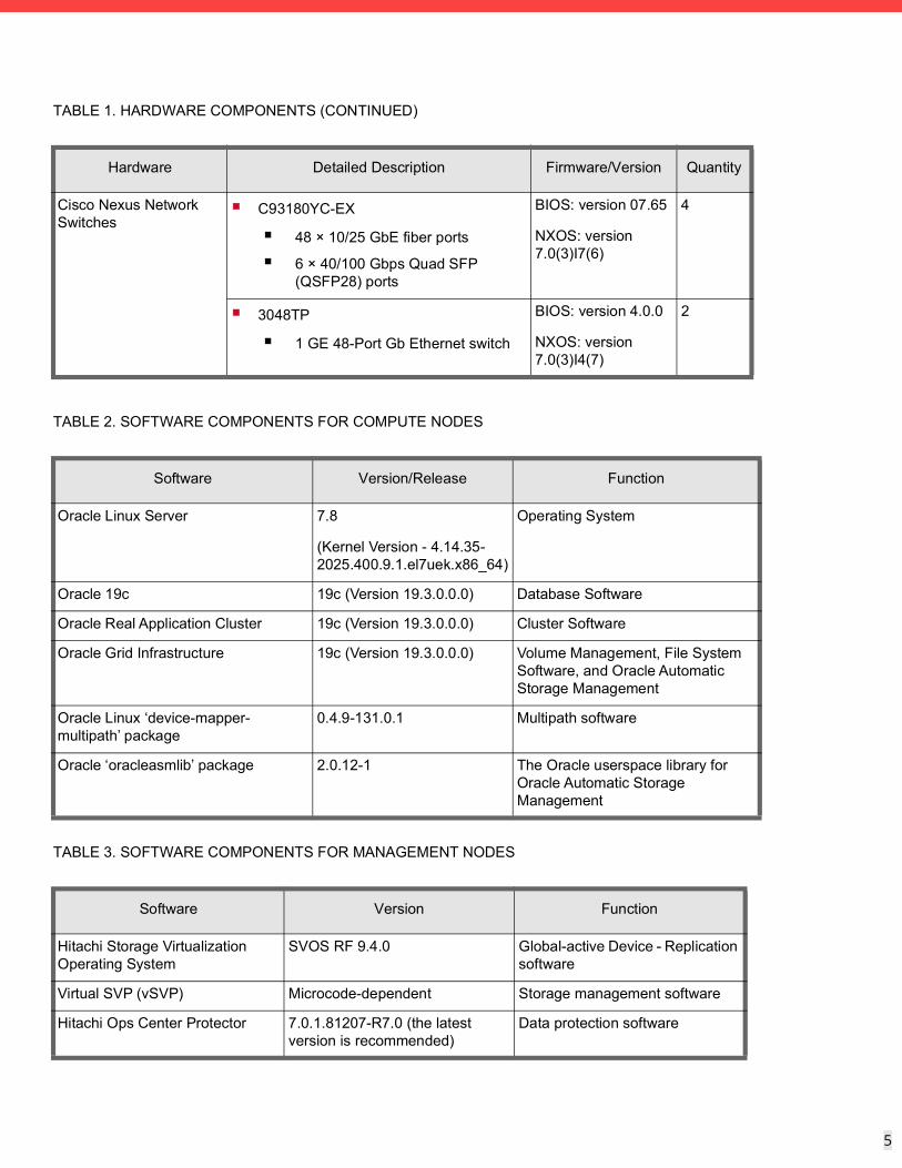
5
5
Cisco Nexus Network Switches
C93180YC-EX
48 × 10/25 GbE fiber ports
6 × 40/100 Gbps Quad SFP (QSFP28) ports
BIOS: version 07.65
NXOS: version 7.0(3)I7(6)
4
3048TP
1 GE 48-Port Gb Ethernet switch
BIOS: version 4.0.0
NXOS: version 7.0(3)I4(7)
2
TABLE 2. SOFTWARE COMPONENTS FOR COMPUTE NODES
Software Version/Release Function
Oracle Linux Server 7.8
(Kernel Version - 4.14.35-2025.400.9.1.el7uek.x86_64)
Operating System
Oracle 19c 19c (Version 19.3.0.0.0) Database Software
Oracle Real Application Cluster 19c (Version 19.3.0.0.0) Cluster Software
Oracle Grid Infrastructure 19c (Version 19.3.0.0.0) Volume Management, File System Software, and Oracle Automatic Storage Management
Oracle Linux ‘device-mapper-multipath’ package
0.4.9-131.0.1 Multipath software
Oracle ‘oracleasmlib’ package 2.0.12-1 The Oracle userspace library for Oracle Automatic Storage Management
TABLE 3. SOFTWARE COMPONENTS FOR MANAGEMENT NODES
Software Version Function
Hitachi Storage Virtualization Operating System
SVOS RF 9.4.0 Global-active Device - Replication software
Virtual SVP (vSVP) Microcode-dependent Storage management software
Hitachi Ops Center Protector 7.0.1.81207-R7.0 (the latest version is recommended)
Data protection software
TABLE 1. HARDWARE COMPONENTS (CONTINUED)
Hardware Detailed Description Firmware/Version Quantity
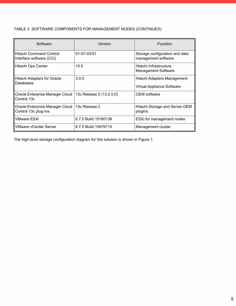
6
6
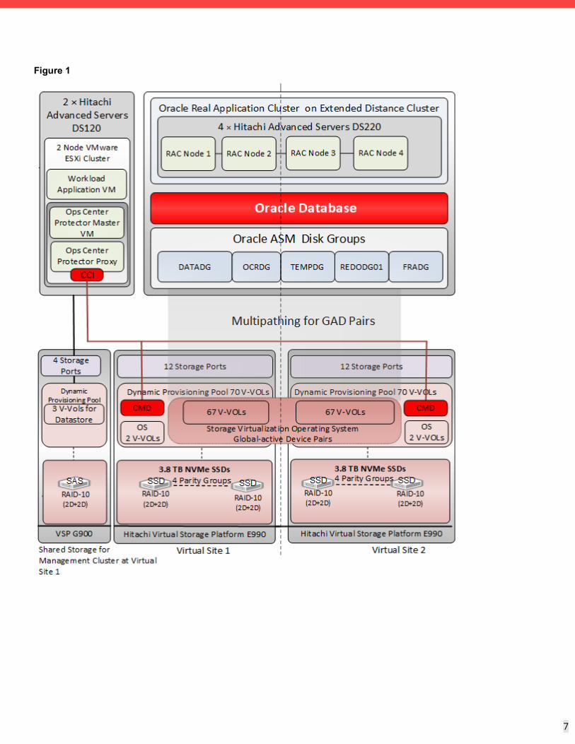
The high-level storage configuration diagram for this solution is shown in Figure 1.
Hitachi Command Control Interface software (CCI)
01-57-03/01 Storage configuration and data management software
Hitachi Ops Center 10.5 Hitachi Infrastructure Management Software
Hitachi Adapters for Oracle Databases
3.0.0 Hitachi Adapters Management
Virtual Appliance Software
Oracle Enterprise Manager Cloud Control 13c
13c Release 2 (13.2.0.0) OEM software
Oracle Enterprise Manager Cloud Control 13c plug-ins
13c Release 2 Hitachi Storage and Server OEM plugins
VMware ESXi 6.7.0 Build 15160138 ESXi for management nodes
VMware vCenter Server 6.7.0 Build 15976714 Management cluster
TABLE 3. SOFTWARE COMPONENTS FOR MANAGEMENT NODES (CONTINUED)
Software Version Function
7
7
Figure 1
8
8
Table 4 lists the storage pool configuration used for this solution. In the current configuration a single pool is used for Operating System (OS), command device (CMD) and Oracle LDEVs. However, you can create OS, CMD and Oracle LDEVs in different storage pools, as needed.
TABLE 4. STORAGE POOL CONFIGURATION
Site Site 1 Site 2
Pool Name Oracle_Pool Oracle_Pool
Pool Type Dynamic Provisioning Dynamic Provisioning
RAID Group 1-11 – 1-14 1-11 – 1-14
RAID Level RAID-10 (2D+2D) RAID-10 (2D+2D)
Drive Type 3.8 TB SSDs 3.8 TB SSDs
Number of Drives 16 16
Number of Pool Volume LDEVs
32 32
Pool Volume LDEV size 880 GB 880 GB
Pool Capacity 27.5 TB 27.5 TB
9
9
Table 5 lists the logical storage configuration used in this solution.
TABLE 5. LOGICAL STORAGE CONFIGURATION
Site Site 1 Site 2
Pool ID Oracle_Pool Oracle_Pool
Number of vVols
1 2 67 P-VOLs 1 2 67 S-VOLs
vVOL Size
100 MB 380 GB 3 × 15 GB, 32 × 200 GB, 16 × 20 GB, 8 × 240 GB, 8 x 2.0 TB
100 MB 380 GB 3 × 15 GB, 32 × 200 GB, 16 × 20 GB, 8 × 240 GB, 8 x 2.0 TB
Purpose Command Device
OS Oracle ASM Disk Groups
OCRDG
DATADG
REDODG
TEMPDG
FRADG
Command Device
OS Oracle ASM Disk Groups
OCRDG
DATADG
REDODG
TEMPDG
FRADG
Storage Port
5C, 6C 1A, 1B, 1C, 1D, 2A, 2B, 2C, 2D
5C, 6C 1A, 1B, 1C, 1D, 2A, 2B, 2C, 2D
TABLE 6. VSP G900 CONFIGURATION FOR MANAGEMENT SERVERS
Item Value/Description
Purpose VMware Datastores
CCI device
RAID level RAID-10 (2D+2D)
Drive type 6.0 TB 7.2K RPM SAS
Number of drives 4
Number of spare drives 2
Number of LDEVs 3
LDEV size(s) 3000 GB
Number and size of CCI devices 1 × 100 MB
Storage port for management servers 7A, 7B, 8A, 8B
10
10
An additional RAID group consisting of four 3 TB 7.2k RPM SAS drives configured as RAID-10 (2D+2D) was used as shared storage for the management server cluster. A 3 TB LUN and a command device were mapped to four storage ports.
Additional LUNs can be mapped, if required. While the test environment was configured using a dedicated SAS RAID group for the management server cluster, this can be configured as a dedicated SSD RAID group, a dedicated HDP pool, or it can use capacity on the HDP pool configured for the Oracle environment depending on customer requirements.
Database LayoutThe database layout design follows the recommended best practices from Hitachi Vantara when using Hitachi Virtual Storage Platform E990 for small random I/O traffic, such as OLTP transactions, and for large I/O traffic, such as OLAP. The layout also considers the Oracle ASM best practices when using Hitachi storage systems. Base the storage design for the database layout on the requirements of your specific application implementation. The design can vary greatly from one implementation to another based on the RAID configuration and number of drives used during the implementation. The components in this solution can be used in various deployment scenarios to provide the right balance between performance and ease of management for a given scenario.
Oracle ASM Configuration
Data and Indexes Tablespace — Assign an ASM disk group with external redundancy for the data and index tablespaces.
TEMP Tablespace — Place the TEMP tablespace in the Data ASM disk group.
UNDO Tablespace — Create an UNDO tablespace in this configuration within the Oracle Data ASM disk group. Assign one UNDO tablespace for each node in the Oracle RAC environment.
Online REDO Logs — Create an ASM disk group with external redundancy for Oracle online REDO logs.
Oracle Cluster Registry and Voting Disk — Create an ASM disk group with normal redundancy to contain the OCR and voting disks and to protect against single disk failure to avoid loss of cluster availability. Place each of these files in this configuration in the OCR ASM disk groups.
Database Block Size Settings — Set the database block size to 8 KB.
ASM FILE SYSTEM I/O Settings — Set the Oracle ASM I/O operations for database files as follows:
RAC configuration — Yes
ASM — Yes, Oracle RAC Database
Table 7 shows the Oracle Environment Parameters.
TABLE 7. ORACLE ASM AND DATABASE PARAMETERS
Category Item Value
Oracle RAC option RAC configuration Yes
ASM Yes – to support Oracle RAC database
11
11
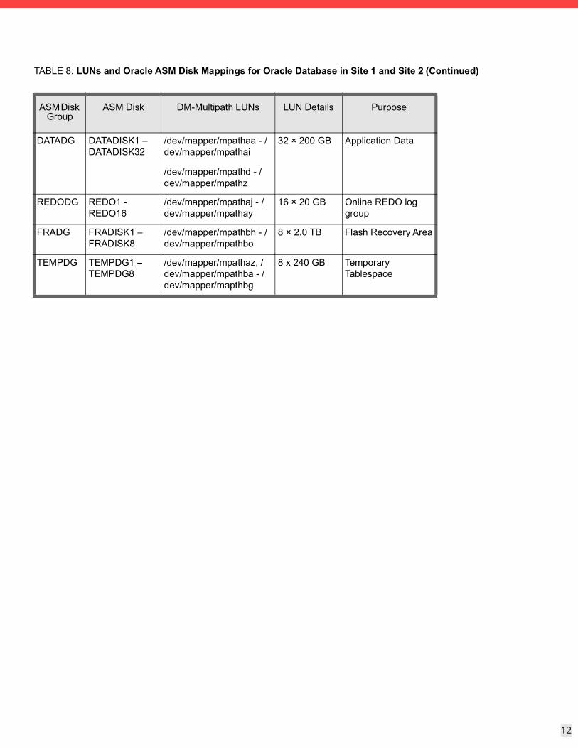
Table 8 shows the details of the disk mappings from the LUNs to the ASM disk groups for Oracle RAC Database tablespaces.
Oracle ASM environment parameters
OCR 3 × 15 GB
DATA 32 × 200 GB
REDO 16 × 20 GB
TEMP 8 × 240 GB
FRA 8 × 2,000 GB
Oracle Database environment parameters
SGA_TARGET 384 GB
PGA_AGGREGATE_TARGET 154 GB
DB_CACHE_SIZE 172 GB
DB_KEEP_CACHE_SIZE 76 GB
DB_RECYCLE_CACHE_SIZE 20 GB
LOG_BUFFER 512 MB
USE_LARGE_PAGES TRUE
FILESYSTEMIO_OPTIONS SETALL
DB_FILE_MULTIBLOCK_READ_COUNT
128
DISK_ASYNCH_IO TRUE
TABLE 8. LUNs and Oracle ASM Disk Mappings for Oracle Database in Site 1 and Site 2
ASM Disk Group
ASM Disk DM-Multipath LUNs LUN Details Purpose
NA NA /dev/mapper/mpatha 4 × 380 GB OS and Oracle RAC cluster ware and database binary
OCRDG OCR1 - OCR3 /dev/mapper/mpathaa - /dev/mapper/mpathac
3 × 15 GB Oracle Cluster Registry and Voting Disk
TABLE 7. ORACLE ASM AND DATABASE PARAMETERS (CONTINUED)
Category Item Value
12
12
DATADG DATADISK1 – DATADISK32
/dev/mapper/mpathaa - /dev/mapper/mpathai
/dev/mapper/mpathd - /dev/mapper/mpathz
32 × 200 GB Application Data
REDODG REDO1 - REDO16
/dev/mapper/mpathaj - /dev/mapper/mpathay
16 × 20 GB Online REDO log group
FRADG FRADISK1 – FRADISK8
/dev/mapper/mpathbh - /dev/mapper/mpathbo
8 × 2.0 TB Flash Recovery Area
TEMPDG TEMPDG1 – TEMPDG8
/dev/mapper/mpathaz, /dev/mapper/mpathba - /dev/mapper/mapthbg
8 x 240 GB Temporary Tablespace
TABLE 8. LUNs and Oracle ASM Disk Mappings for Oracle Database in Site 1 and Site 2 (Continued)
ASM Disk Group
ASM Disk DM-Multipath LUNs LUN Details Purpose
13
13
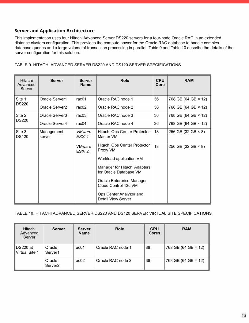
Server and Application ArchitectureThis implementation uses four Hitachi Advanced Server DS220 servers for a four-node Oracle RAC in an extended distance clusters configuration. This provides the compute power for the Oracle RAC database to handle complex database queries and a large volume of transaction processing in parallel. Table 9 and Table 10 describe the details of the server configuration for this solution.
TABLE 9. HITACHI ADVANCED SERVER DS220 AND DS120 SERVER SPECIFICATIONS
Hitachi Advanced
Server
Server Server Name
Role CPU Core
RAM
Site 1 DS220
Oracle Server1 rac01 Oracle RAC node 1 36 768 GB (64 GB × 12)
Oracle Server2 rac02 Oracle RAC node 2 36 768 GB (64 GB × 12)
Site 2 DS220
Oracle Server3 rac03 Oracle RAC node 3 36 768 GB (64 GB × 12)
Oracle Server4 rac04 Oracle RAC node 4 36 768 GB (64 GB × 12)
Site 3 DS120
Management server
VMware ESXi 1
Hitachi Ops Center Protector Master VM
Hitachi Ops Center Protector Proxy VM
Workload application VM
Manager for Hitachi Adapters for Oracle Database VM
Oracle Enterprise Manager Cloud Control 13c VM
Ops Center Analyzer and Detail View Server
18 256 GB (32 GB × 8)
VMware ESXi 2
18 256 GB (32 GB × 8)
TABLE 10. HITACHI ADVANCED SERVER DS220 AND DS120 SERVER VIRTUAL SITE SPECIFICATIONS
Hitachi Advanced
Server
Server Server Name
Role CPU Cores
RAM
DS220 at Virtual Site 1
Oracle Server1
rac01 Oracle RAC node 1 36 768 GB (64 GB × 12)
Oracle Server2
rac02 Oracle RAC node 2 36 768 GB (64 GB × 12)
14
14
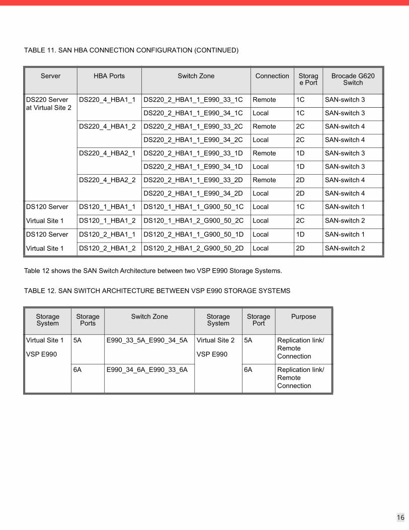
SAN ArchitectureMap the provisioned LDEVs to multiple ports on two Hitachi Virtual Storage Platform E990 storage systems. These LDEV port assignments provide multiple paths to the storage system from the host for high availability. Table 11 lists SAN HBA connections for mapping the provisioned LDEVs.
Virtual Site 1
12 SAN switch connections for VSP E990 storage ports
8 SAN switch connections for server HBA ports
Management cluster connections
4 SAN switch connections for VSP G900 storage ports
4 SAN switch connections for server HBA ports
Virtual Site 2
12 SAN switch connections for VSP E990 storage ports
8 SAN switch connections for server HBA ports
DS220 at Virtual Site 2
Oracle Server3
rac03 Oracle RAC node 3 36 768 GB (64 GB × 12)
Oracle Server4
rac04 Oracle RAC node 4 36 768 GB (64 GB × 12)
DS120 at Virtual Site 1
Management server
VMware ESXi 1
Hitachi Ops Center Protector Master VM
Hitachi Ops Center Protector Proxy VM
Workload application VM
Manager for Hitachi Adapters for Oracle Database VM
Oracle Enterprise Manager Cloud Control 13c VM
Ops Center Analyzer and Detail View Server
Ops Center Probe VM
18 256 GB (32 GB × 8)
VMware ESXi 2
18 256 GB (32 GB × 8)
TABLE 10. HITACHI ADVANCED SERVER DS220 AND DS120 SERVER VIRTUAL SITE SPECIFICATIONS
Hitachi Advanced
Server
Server Server Name
Role CPU Cores
RAM
15
15
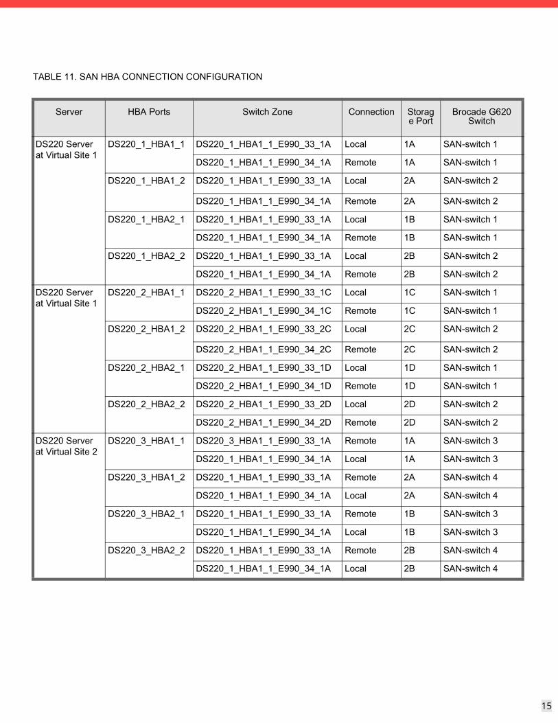
TABLE 11. SAN HBA CONNECTION CONFIGURATION
Server HBA Ports Switch Zone Connection Storage Port
Brocade G620 Switch
DS220 Server at Virtual Site 1
DS220_1_HBA1_1 DS220_1_HBA1_1_E990_33_1A Local 1A SAN-switch 1
DS220_1_HBA1_1_E990_34_1A Remote 1A SAN-switch 1
DS220_1_HBA1_2 DS220_1_HBA1_1_E990_33_1A Local 2A SAN-switch 2
DS220_1_HBA1_1_E990_34_1A Remote 2A SAN-switch 2
DS220_1_HBA2_1 DS220_1_HBA1_1_E990_33_1A Local 1B SAN-switch 1
DS220_1_HBA1_1_E990_34_1A Remote 1B SAN-switch 1
DS220_1_HBA2_2 DS220_1_HBA1_1_E990_33_1A Local 2B SAN-switch 2
DS220_1_HBA1_1_E990_34_1A Remote 2B SAN-switch 2
DS220 Server at Virtual Site 1
DS220_2_HBA1_1 DS220_2_HBA1_1_E990_33_1C Local 1C SAN-switch 1
DS220_2_HBA1_1_E990_34_1C Remote 1C SAN-switch 1
DS220_2_HBA1_2 DS220_2_HBA1_1_E990_33_2C Local 2C SAN-switch 2
DS220_2_HBA1_1_E990_34_2C Remote 2C SAN-switch 2
DS220_2_HBA2_1 DS220_2_HBA1_1_E990_33_1D Local 1D SAN-switch 1
DS220_2_HBA1_1_E990_34_1D Remote 1D SAN-switch 1
DS220_2_HBA2_2 DS220_2_HBA1_1_E990_33_2D Local 2D SAN-switch 2
DS220_2_HBA1_1_E990_34_2D Remote 2D SAN-switch 2
DS220 Server at Virtual Site 2
DS220_3_HBA1_1 DS220_3_HBA1_1_E990_33_1A Remote 1A SAN-switch 3
DS220_1_HBA1_1_E990_34_1A Local 1A SAN-switch 3
DS220_3_HBA1_2 DS220_1_HBA1_1_E990_33_1A Remote 2A SAN-switch 4
DS220_1_HBA1_1_E990_34_1A Local 2A SAN-switch 4
DS220_3_HBA2_1 DS220_1_HBA1_1_E990_33_1A Remote 1B SAN-switch 3
DS220_1_HBA1_1_E990_34_1A Local 1B SAN-switch 3
DS220_3_HBA2_2 DS220_1_HBA1_1_E990_33_1A Remote 2B SAN-switch 4
DS220_1_HBA1_1_E990_34_1A Local 2B SAN-switch 4
16
16
Table 12 shows the SAN Switch Architecture between two VSP E990 Storage Systems.
DS220 Server at Virtual Site 2
DS220_4_HBA1_1 DS220_2_HBA1_1_E990_33_1C Remote 1C SAN-switch 3
DS220_2_HBA1_1_E990_34_1C Local 1C SAN-switch 3
DS220_4_HBA1_2 DS220_2_HBA1_1_E990_33_2C Remote 2C SAN-switch 4
DS220_2_HBA1_1_E990_34_2C Local 2C SAN-switch 4
DS220_4_HBA2_1 DS220_2_HBA1_1_E990_33_1D Remote 1D SAN-switch 3
DS220_2_HBA1_1_E990_34_1D Local 1D SAN-switch 3
DS220_4_HBA2_2 DS220_2_HBA1_1_E990_33_2D Remote 2D SAN-switch 4
DS220_2_HBA1_1_E990_34_2D Local 2D SAN-switch 4
DS120 Server
Virtual Site 1
DS120_1_HBA1_1 DS120_1_HBA1_1_G900_50_1C Local 1C SAN-switch 1
DS120_1_HBA1_2 DS120_1_HBA1_2_G900_50_2C Local 2C SAN-switch 2
DS120 Server
Virtual Site 1
DS120_2_HBA1_1 DS120_2_HBA1_1_G900_50_1D Local 1D SAN-switch 1
DS120_2_HBA1_2 DS120_2_HBA1_2_G900_50_2D Local 2D SAN-switch 2
TABLE 12. SAN SWITCH ARCHITECTURE BETWEEN VSP E990 STORAGE SYSTEMS
Storage System
Storage Ports
Switch Zone Storage System
Storage Port
Purpose
Virtual Site 1
VSP E990
5A E990_33_5A_E990_34_5A Virtual Site 2
VSP E990
5A Replication link/ Remote Connection
6A E990_34_6A_E990_33_6A 6A Replication link/ Remote Connection
TABLE 11. SAN HBA CONNECTION CONFIGURATION (CONTINUED)
Server HBA Ports Switch Zone Connection Storage Port
Brocade G620 Switch
17
17
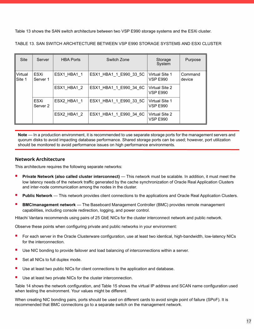
Table 13 shows the SAN switch architecture between two VSP E990 storage systems and the ESXi cluster.
Note — In a production environment, it is recommended to use separate storage ports for the management servers and quorum disks to avoid impacting database performance. Shared storage ports can be used; however, port utilization should be monitored to avoid performance issues on high performance environments.
Network ArchitectureThis architecture requires the following separate networks:
Private Network (also called cluster interconnect) — This network must be scalable. In addition, it must meet the low latency needs of the network traffic generated by the cache synchronization of Oracle Real Application Clusters and inter-node communication among the nodes in the cluster.
Public Network — This network provides client connections to the applications and Oracle Real Application Clusters.
BMC/management network — The Baseboard Management Controller (BMC) provides remote management capabilities, including console redirection, logging, and power control.
Hitachi Vantara recommends using pairs of 25 GbE NICs for the cluster interconnect network and public network.
Observe these points when configuring private and public networks in your environment:
For each server in the Oracle Clusterware configuration, use at least two identical, high-bandwidth, low-latency NICs for the interconnection.
Use NIC bonding to provide failover and load balancing of interconnections within a server.
Set all NICs to full duplex mode.
Use at least two public NICs for client connections to the application and database.
Use at least two private NICs for the cluster interconnection.
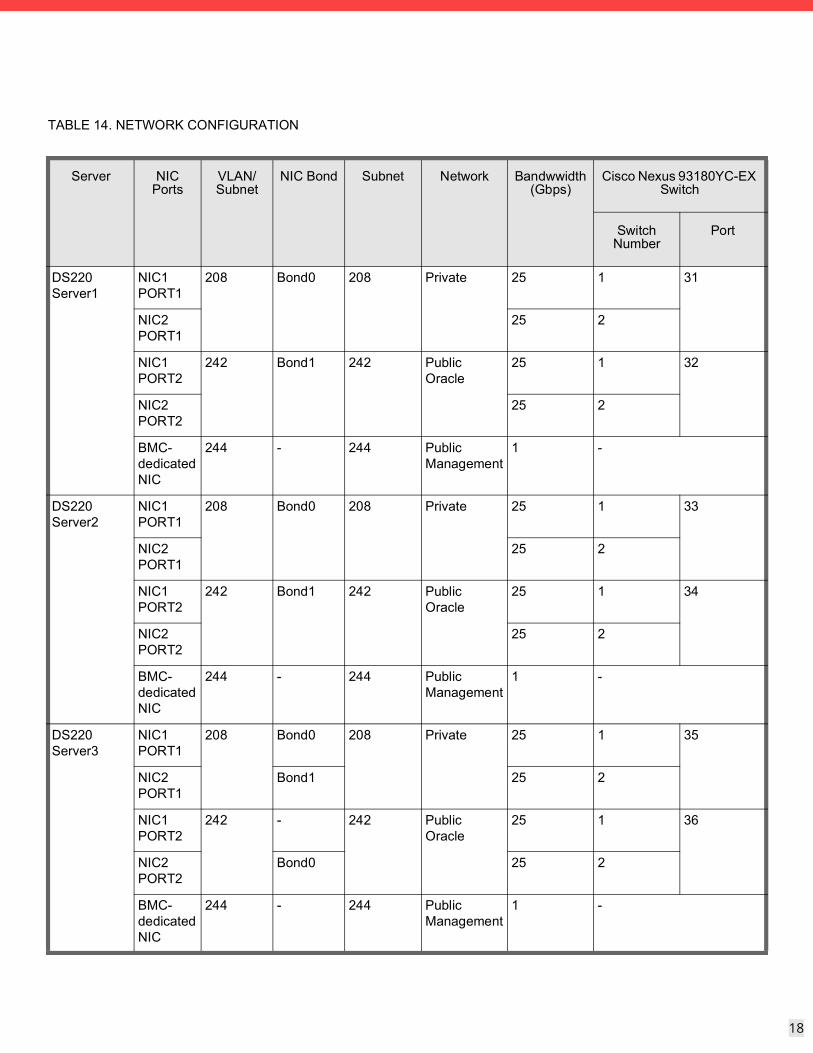
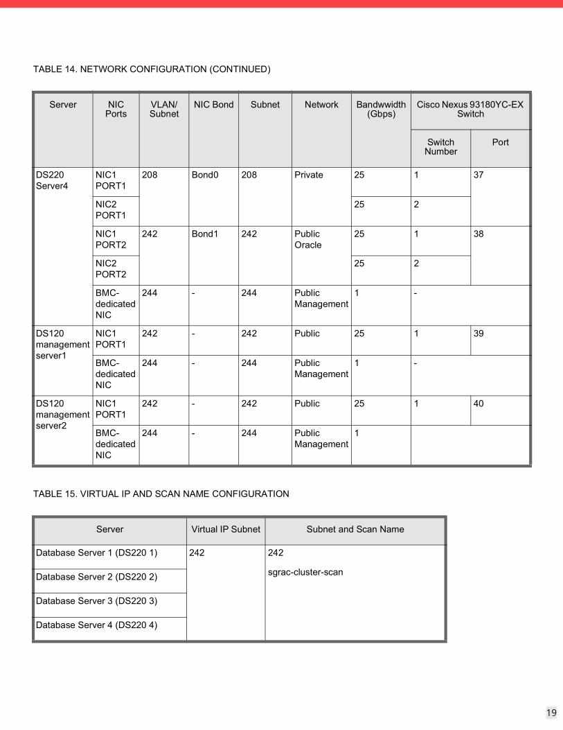
Table 14 shows the network configuration, and Table 15 shows the virtual IP address and SCAN name configuration used when testing the environment. Your values might be different.
When creating NIC bonding pairs, ports should be used on different cards to avoid single point of failure (SPoF). It is recommended that BMC connections go to a separate switch on the management network.
TABLE 13. SAN SWITCH ARCHITECTURE BETWEEN VSP E990 STORAGE SYSTEMS AND ESXI CLUSTER
Site Server HBA Ports Switch Zone Storage System
Purpose
Virtual Site 1
ESXi Server 1
ESX1_HBA1_1 ESX1_HBA1_1_E990_33_5C Virtual Site 1 VSP E990
Command device
ESX1_HBA1_2 ESX1_HBA1_1_E990_34_6C Virtual Site 2 VSP E990
ESXi Server 2
ESX2_HBA1_1 ESX1_HBA1_1_E990_33_5C Virtual Site 1 VSP E990
ESX2_HBA1_2 ESX1_HBA1_1_E990_34_6C Virtual Site 2 VSP E990
18
18
TABLE 14. NETWORK CONFIGURATION
Server NIC Ports
VLAN/Subnet
NIC Bond Subnet Network Bandwwidth (Gbps)
Cisco Nexus 93180YC-EX Switch
Switch Number
Port
DS220 Server1
NIC1 PORT1
208 Bond0 208 Private 25 1 31
NIC2 PORT1
25 2
NIC1 PORT2
242 Bond1 242 Public Oracle
25 1 32
NIC2 PORT2
25 2
BMC- dedicated NIC
244 - 244 Public Management
1 -
DS220 Server2
NIC1 PORT1
208 Bond0 208 Private 25 1 33
NIC2 PORT1
25 2
NIC1 PORT2
242 Bond1 242 Public Oracle
25 1 34
NIC2 PORT2
25 2
BMC- dedicated NIC
244 - 244 Public Management
1 -
DS220 Server3
NIC1 PORT1
208 Bond0 208 Private 25 1 35
NIC2 PORT1
Bond1 25 2
NIC1 PORT2
242 - 242 Public Oracle
25 1 36
NIC2 PORT2
Bond0 25 2
BMC- dedicated NIC
244 - 244 Public Management
1 -
19
19
DS220 Server4
NIC1 PORT1
208 Bond0 208 Private 25 1 37
NIC2 PORT1
25 2
NIC1 PORT2
242 Bond1 242 Public Oracle
25 1 38
NIC2 PORT2
25 2
BMC- dedicated NIC
244 - 244 Public Management
1 -
DS120 management server1
NIC1 PORT1
242 - 242 Public 25 1 39
BMC- dedicated NIC
244 - 244 Public Management
1 -
DS120 management server2
NIC1 PORT1
242 - 242 Public 25 1 40
BMC- dedicated NIC
244 - 244 Public Management
1
TABLE 15. VIRTUAL IP AND SCAN NAME CONFIGURATION
Server Virtual IP Subnet Subnet and Scan Name
Database Server 1 (DS220 1) 242 242
sgrac-cluster-scanDatabase Server 2 (DS220 2)
Database Server 3 (DS220 3)
Database Server 4 (DS220 4)
TABLE 14. NETWORK CONFIGURATION (CONTINUED)
Server NIC Ports
VLAN/Subnet
NIC Bond Subnet Network Bandwwidth (Gbps)
Cisco Nexus 93180YC-EX Switch
Switch Number
Port
20
20
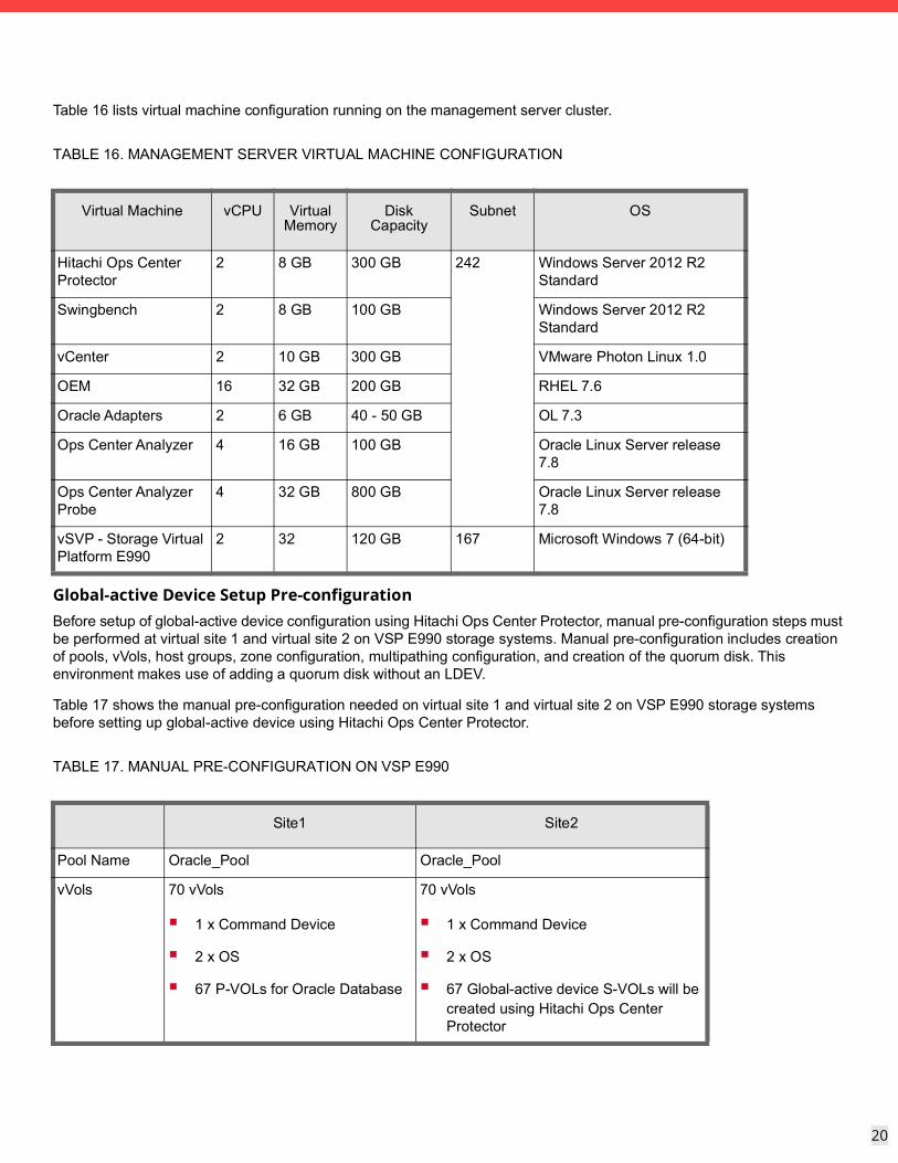
Table 16 lists virtual machine configuration running on the management server cluster.
Global-active Device Setup Pre-configurationBefore setup of global-active device configuration using Hitachi Ops Center Protector, manual pre-configuration steps must be performed at virtual site 1 and virtual site 2 on VSP E990 storage systems. Manual pre-configuration includes creation of pools, vVols, host groups, zone configuration, multipathing configuration, and creation of the quorum disk. This environment makes use of adding a quorum disk without an LDEV.
Table 17 shows the manual pre-configuration needed on virtual site 1 and virtual site 2 on VSP E990 storage systems before setting up global-active device using Hitachi Ops Center Protector.
TABLE 16. MANAGEMENT SERVER VIRTUAL MACHINE CONFIGURATION
Virtual Machine vCPU Virtual Memory
Disk Capacity
Subnet OS
Hitachi Ops Center Protector
2 8 GB 300 GB 242 Windows Server 2012 R2 Standard
Swingbench 2 8 GB 100 GB Windows Server 2012 R2 Standard
vCenter 2 10 GB 300 GB VMware Photon Linux 1.0
OEM 16 32 GB 200 GB RHEL 7.6
Oracle Adapters 2 6 GB 40 - 50 GB OL 7.3
Ops Center Analyzer 4 16 GB 100 GB Oracle Linux Server release 7.8
Ops Center Analyzer Probe
4 32 GB 800 GB Oracle Linux Server release 7.8
vSVP - Storage Virtual Platform E990
2 32 120 GB 167 Microsoft Windows 7 (64-bit)
TABLE 17. MANUAL PRE-CONFIGURATION ON VSP E990
Site1 Site2
Pool Name Oracle_Pool Oracle_Pool
vVols 70 vVols
1 x Command Device
2 x OS
67 P-VOLs for Oracle Database
70 vVols
1 x Command Device
2 x OS
67 Global-active device S-VOLs will be created using Hitachi Ops Center Protector
21
21
Solution ImplementationImplementing this solution requires doing the following high-level procedures using the Hitachi Ops Center Protector Web user interface.
Deploy and Configure Hitachi Ops Center Protector1. Install the Hitachi Ops Center Protector Master Node
2. Create the Hitachi Ops Center Protector Nodes
3. Define the Hitachi Ops Center Protector Policy
4. Define Hitachi Ops Center Protector Data Flow
Your checklist might vary based on your environment.
Host Groups 22 Host Groups
16 x Oracle ASM Disks
(8 x Local, 8x Remote)
2 x Remote Paths
2 x Operating Systems
2 x Command Device
22 Host Groups
16 x Oracle ASM Disks
(8 x Local, 8x Remote)
2 x Remote Paths
2 x Operating Systems
2 x Command Device
Zone configuration
22 Zones 22 Zones
Quorum disk Add quorum disk without using LDEV Add quorum disk without using LDEV
Multipathing 4 owner paths per server for Oracle database P-VOLs
4 owner paths per server for Oracle database P-VOLs
(4 non-owner paths will be added after global-active device setup, with a total 8 of paths per server Oracle database P-VOLs)
See Table 11, “SAN HBA Connection Configuration,” on page 15 for details of owner (local) and non-owner (remote) paths
(4 non-owner paths will be added after global-active device setup, with a total of 8 paths per server Oracle database S-VOLs)
See Table 11, “SAN HBA Connection Configuration,” on page 15 for details of owner (local) and non-owner (remote) paths
TABLE 17. MANUAL PRE-CONFIGURATION ON VSP E990 (CONTINUED)
Site1 Site2
22
22
Install the Hitachi Ops Center Protector Master Node
The Hitachi Ops Center Protector Installation Guide and User Guide are in the documentation folder, and the Hitachi Ops Center Protector installable is in the Linux/Windows folder of the Hitachi Ops Center Protector ISO image. Download the latest version of the media kit to get the Hitachi Ops Center Protector ISO image. Go to https://knowledge.hitachivantara.com/Documents/Management_Software/Ops_Center or contact your local Hitachi Vantara representative.
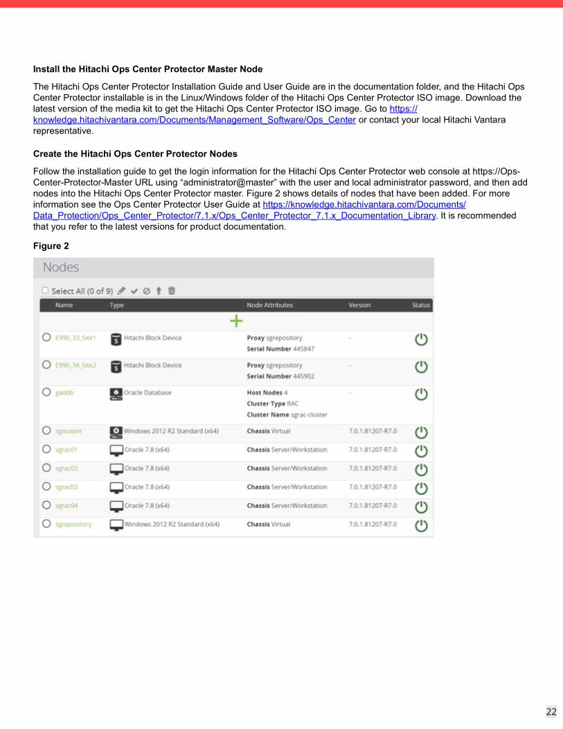
Create the Hitachi Ops Center Protector Nodes
Follow the installation guide to get the login information for the Hitachi Ops Center Protector web console at https://Ops-Center-Protector-Master URL using “administrator@master” with the user and local administrator password, and then add nodes into the Hitachi Ops Center Protector master. Figure 2 shows details of nodes that have been added. For more information see the Ops Center Protector User Guide at https://knowledge.hitachivantara.com/Documents/Data_Protection/Ops_Center_Protector/7.1.x/Ops_Center_Protector_7.1.x_Documentation_Library. It is recommended that you refer to the latest versions for product documentation.
Figure 2
23
23
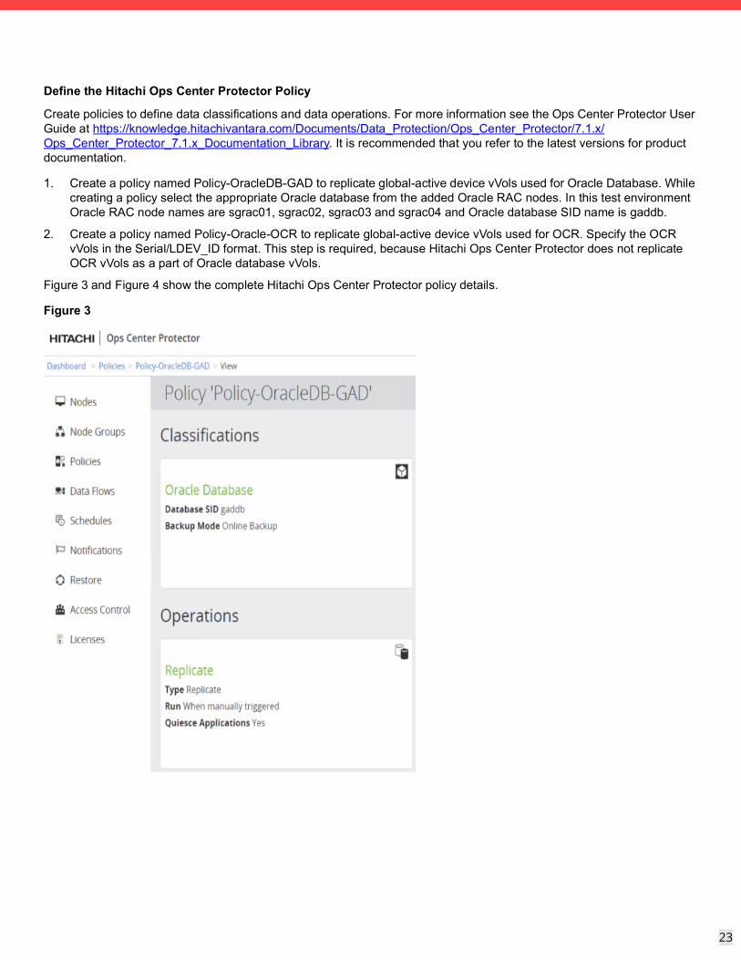
Define the Hitachi Ops Center Protector Policy
Create policies to define data classifications and data operations. For more information see the Ops Center Protector User Guide at https://knowledge.hitachivantara.com/Documents/Data_Protection/Ops_Center_Protector/7.1.x/Ops_Center_Protector_7.1.x_Documentation_Library. It is recommended that you refer to the latest versions for product documentation.
1. Create a policy named Policy-OracleDB-GAD to replicate global-active device vVols used for Oracle Database. While creating a policy select the appropriate Oracle database from the added Oracle RAC nodes. In this test environment Oracle RAC node names are sgrac01, sgrac02, sgrac03 and sgrac04 and Oracle database SID name is gaddb.
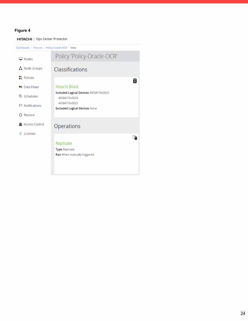
2. Create a policy named Policy-Oracle-OCR to replicate global-active device vVols used for OCR. Specify the OCR vVols in the Serial/LDEV_ID format. This step is required, because Hitachi Ops Center Protector does not replicate OCR vVols as a part of Oracle database vVols.
Figure 3 and Figure 4 show the complete Hitachi Ops Center Protector policy details.
Figure 3
24
24
Figure 4
25
25
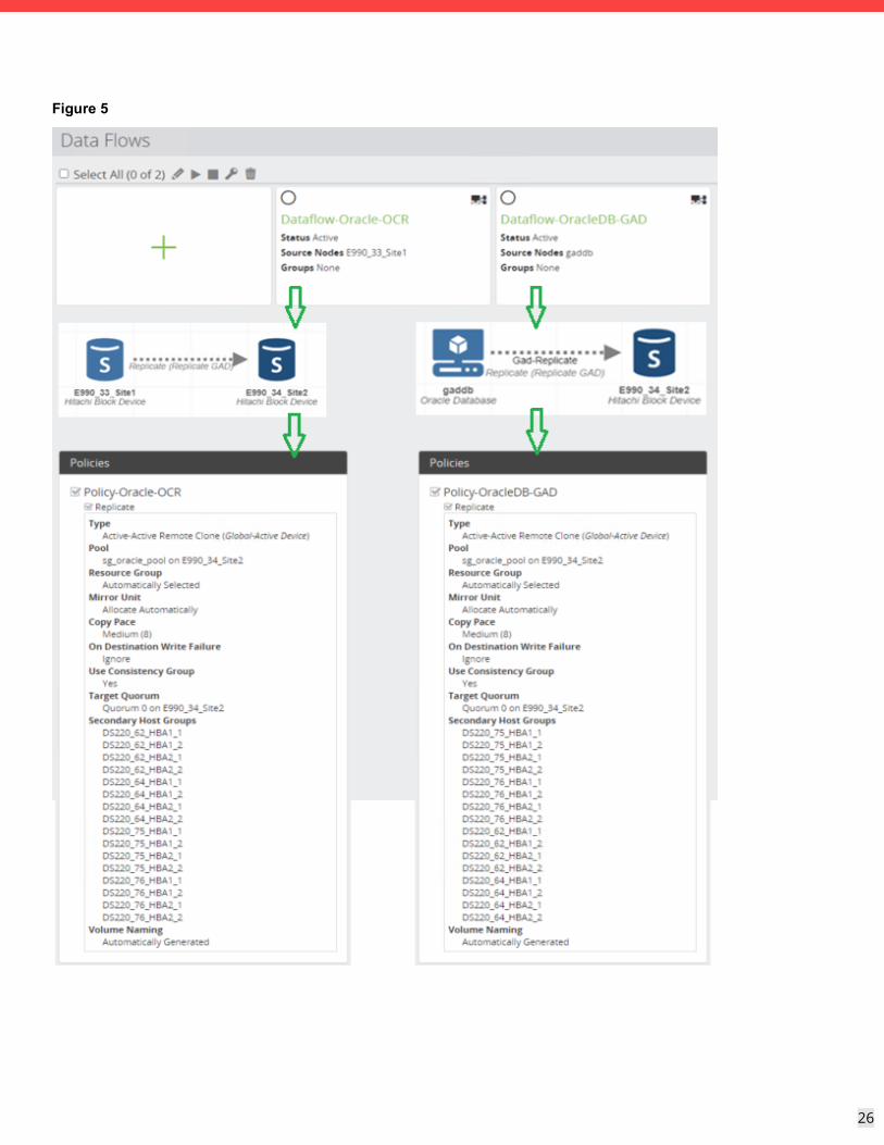
Define Hitachi Ops Center Protector Data Flow
Data flow diagrams identify both physical and logical entities and the connections between them. The data that is to be protected flows from a Source Node to a Destination Node during the data protection process. For more information refer Ops Center Protector user guide to know on core concepts for creating data flows find the Ops Center Protector user guide for version 7.1 at https://knowledge.hitachivantara.com/Documents/Data_Protection/Ops_Center_Protector/7.1.x/Ops_Center_Protector_7.1.x_Documentation_Library. It is recommended to refer to the latest versions for product documentation. Below are the steps to create dataflow to achieve global-active device replication. Create a data flow named ‘Dataflow-OracleDB-GAD’ to global-active device replication for Oracle database vVols.
1. Select the node gaddb and assign the policy Policy-OracleDB-GAD. Select the appropriate node that is type Oracle Database for your environment.
2. Select the replication mover type to Continuous.
3. For the node E990_34_Site2, select Creation Mode as Configure New Replication and replication type as Active-Active Remote Clone on the next page, and then click Next.
4. Select the target pool where global-active device replicated vVols will be created.
5. Select the quorum disk from the available quorum disks and then click Next.
In this environment Quorum 0 was used as the quorum disk.
Note that the Quorum disk is created on both VSP E990 storage systems without using LDEVs from an external storage system.
6. Select Automatically Selected for the resource group and then click Next.
7. Select secondary host groups where vVols will be mapped and then click Next.
8. Select Match Origin for secondary LDEVs naming options.
9. Create a data flow named Dataflow-Oracle-OCR to global-active device replication for Oracle OCR vVols.
10. Select node E990_33-Site1 and assign the policy Policy-Oracle-OCR.
11. Select the replication mover type to Continuous.
For E990_34_Site2 select Select Creation Mode as Configure New Replication and replication type as Active-Active Remote Clone on the next page and click Next.
12. Select the target pool where global-active device replication vVols will be created.
13. Select the Quorum disk from the available quorum disks and click Next.
In this environment Quorum 0 was used as the quorum disk.
14. Select Automatically Selected for the resource group and click Next.
15. Select secondary host groups where vVols will be mapped and click Next.
16. Select Match Origin for secondary LDEVs naming options.
Figure 5 shows the complete Hitachi Ops Center Protector data flow details.
26
26
Figure 5
27
27
Solution TestsTesting this solution consisted of the following procedures:
Perform Global-active Device Replication for the Oracle Database and OCR Disks to the Secondary VSP E990 Storage.
This procedure explains how to deploy global-active device to add backup and recovery capabilities in an Oracle environment to achieve zero recovery point objective (RPO) and recovery time objective (RTO). The test environment makes use of global-active device without using an external storage system for quorum configuration in a two-site replication environment with Virtual Storage Platform E990 series to provide data protection for Oracle Database.
Recover Oracle Database After Storage Links Failure at Site 2 Storage System.
This procedure explains protecting the Oracle environment against storage link failures. No services are impacted after failure or during recovery time.
Storage Replication Operations using Hitachi Ops Center Protector
This procedure explains how to use Hitachi Ops Center Protector to perform automated two-datacenter swap global-active device replication on demand and automated recovery of global-active device replication in an error or suspended state.
Perform Backup and Recovery Operations using Hitachi Ops Center Protector and Oracle RMAN SBT Integration
Perform Global-active Device Replication for the Oracle Database and OCR Disks to the Secondary VSP E990 StorageThis is how to perform global-active device replication for the Oracle database and OCR disks to the secondary storage using Hitachi Ops Center Protector.
To run the Hitachi Ops Center Protector data flow do the following.
1. Select the appropriate Data Flow and click Activate. The Activate Data Flow(s) dialog box displays with data flow compilation details.
2. Click Activate to run the data flow.
28
28
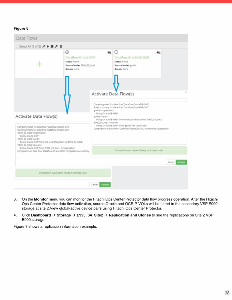
Figure 6
3. On the Monitor menu you can monitor the Hitachi Ops Center Protector data flow progress operation. After the Hitachi Ops Center Protector data flow activation, source Oracle and OCR P-VOLs will be tiered to the secondary VSP E990 storage at site 2.View global-active device pairs using Hitachi Ops Center Protector.
4. Click Dashboard Storage E990_34_Site2 Replication and Clones to see the replications on Site 2 VSP E990 storage.
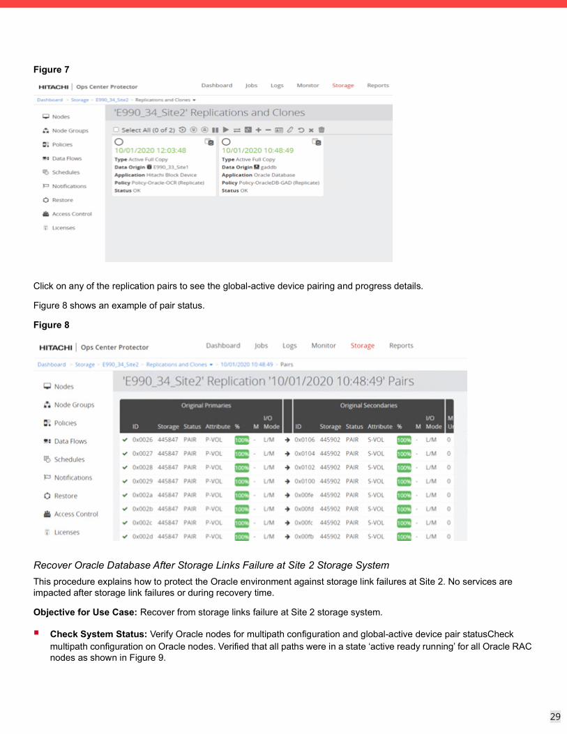
Figure 7 shows a replication information example.
29
29
Figure 7
Click on any of the replication pairs to see the global-active device pairing and progress details.
Figure 8 shows an example of pair status.
Figure 8
Recover Oracle Database After Storage Links Failure at Site 2 Storage SystemThis procedure explains how to protect the Oracle environment against storage link failures at Site 2. No services are impacted after storage link failures or during recovery time.
Objective for Use Case: Recover from storage links failure at Site 2 storage system.
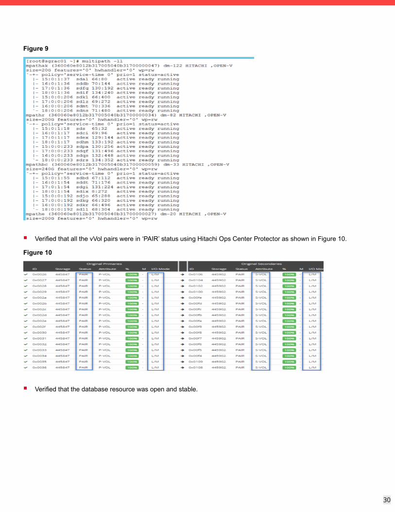
Check System Status: Verify Oracle nodes for multipath configuration and global-active device pair statusCheck multipath configuration on Oracle nodes. Verified that all paths were in a state ‘active ready running’ for all Oracle RAC nodes as shown in Figure 9.
30
30
Figure 9
Verified that all the vVol pairs were in ‘PAIR’ status using Hitachi Ops Center Protector as shown in Figure 10.
Figure 10
Verified that the database resource was open and stable.
31
31
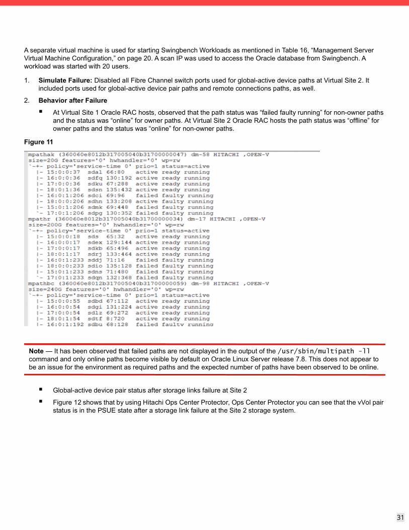
A separate virtual machine is used for starting Swingbench Workloads as mentioned in Table 16, “Management Server Virtual Machine Configuration,” on page 20. A scan IP was used to access the Oracle database from Swingbench. A workload was started with 20 users.
1. Simulate Failure: Disabled all Fibre Channel switch ports used for global-active device paths at Virtual Site 2. It included ports used for global-active device pair paths and remote connections paths, as well.
2. Behavior after Failure
At Virtual Site 1 Oracle RAC hosts, observed that the path status was “failed faulty running” for non-owner paths and the status was “online” for owner paths. At Virtual Site 2 Oracle RAC hosts the path status was “offline” for owner paths and the status was “online” for non-owner paths.
Figure 11
Note — It has been observed that failed paths are not displayed in the output of the /usr/sbin/multipath -ll command and only online paths become visible by default on Oracle Linux Server release 7.8. This does not appear to be an issue for the environment as required paths and the expected number of paths have been observed to be online.
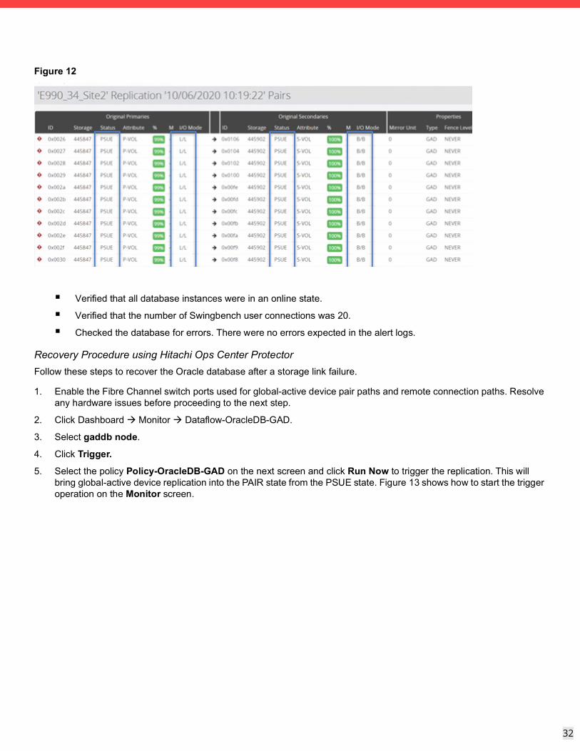
Global-active device pair status after storage links failure at Site 2
Figure 12 shows that by using Hitachi Ops Center Protector, Ops Center Protector you can see that the vVol pair status is in the PSUE state after a storage link failure at the Site 2 storage system.
32
32
Figure 12
Verified that all database instances were in an online state.
Verified that the number of Swingbench user connections was 20.
Checked the database for errors. There were no errors expected in the alert logs.
Recovery Procedure using Hitachi Ops Center ProtectorFollow these steps to recover the Oracle database after a storage link failure.
1. Enable the Fibre Channel switch ports used for global-active device pair paths and remote connection paths. Resolve any hardware issues before proceeding to the next step.
2. Click Dashboard Monitor Dataflow-OracleDB-GAD.
3. Select gaddb node.
4. Click Trigger.
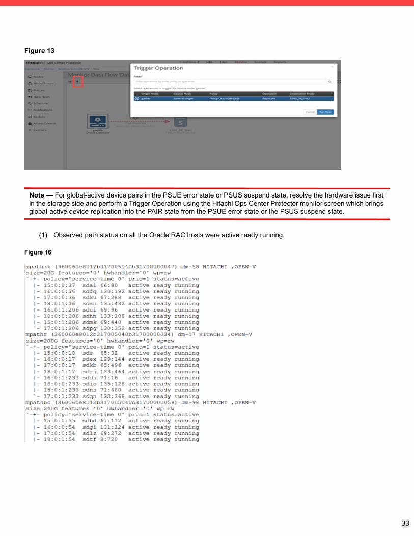
5. Select the policy Policy-OracleDB-GAD on the next screen and click Run Now to trigger the replication. This will bring global-active device replication into the PAIR state from the PSUE state. Figure 13 shows how to start the trigger operation on the Monitor screen.
33
33
Figure 13
Note — For global-active device pairs in the PSUE error state or PSUS suspend state, resolve the hardware issue first in the storage side and perform a Trigger Operation using the Hitachi Ops Center Protector monitor screen which brings global-active device replication into the PAIR state from the PSUE error state or the PSUS suspend state.
(1) Observed path status on all the Oracle RAC hosts were active ready running.
Figure 16
34
34
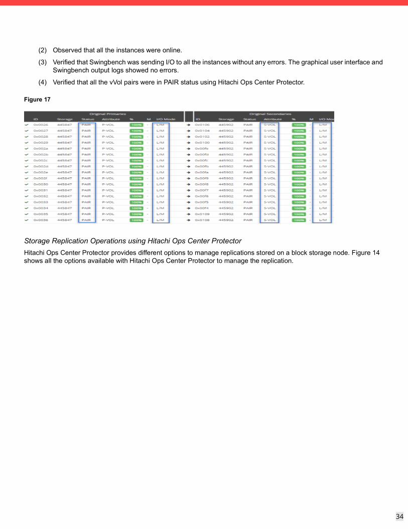
(2) Observed that all the instances were online.
(3) Verified that Swingbench was sending I/O to all the instances without any errors. The graphical user interface and Swingbench output logs showed no errors.
(4) Verified that all the vVol pairs were in PAIR status using Hitachi Ops Center Protector.
Figure 17
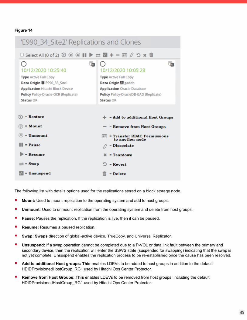
Storage Replication Operations using Hitachi Ops Center ProtectorHitachi Ops Center Protector provides different options to manage replications stored on a block storage node. Figure 14 shows all the options available with Hitachi Ops Center Protector to manage the replication.
35
35
Figure 14
The following list with details options used for the replications stored on a block storage node.
Mount: Used to mount replication to the operating system and add to host groups.
Unmount: Used to unmount replication from the operating system and delete from host groups.
Pause: Pauses the replication. If the replication is live, then it can be paused.
Resume: Resumes a paused replication.
Swap: Swaps direction of global-active device, TrueCopy, and Universal Replicator.
Unsuspend: If a swap operation cannot be completed due to a P-VOL or data link fault between the primary and secondary device, then the replication will enter the SSWS state (suspended for swapping) indicating that the swap is not yet complete. Unsuspend enables the replication process to be re-established once the cause has been resolved.
Add to additional Host groups: This enables LDEVs to be added to host groups in addition to the default HDIDProvisionedHostGroup_RG1 used by Hitachi Ops Center Protector.
Remove from Host Groups: This enables LDEVs to be removed from host groups, including the default HDIDProvisionedHostGroup_RG1 used by Hitachi Ops Center Protector.
36
36
Transfer RBAC permissions to another node: Allows RBAC ownership to be transferred from the current node to another node.
Dissociate: Dissociates a replication that was previously adopted by Hitachi Ops Center Protector. Removes the selected replications from Hitachi Ops Center Protector including state information such as direction and mount location. The replication remains active on the hardware devices.
Revert: Reverts the replication to perform Oracle recovery operation.
Teardown: Tears down a replication using HDID removes the volume pairings on the storage system.
Delete: Deletes the replication record from HDID. The replication is also removed from the block storage device.
Hitachi Block-based Two-datacenter Replication Swapping (Takeover/Takeback) Using Hitachi Ops Center Pro-tector
Hitachi Ops Center Protector allows users to swap the direction of global-active device, TrueCopy, and Universal Replicator. When a replication is swapped, the S-VOL takes over the role of the primary volume and the P-VOL takes over the role of the secondary volume. A swapped replication can be swapped back to its normal state with the P-VOL as the primary and S-VOL as the secondary. A swap operation is typically performed either because maintenance is required, an application failure has occurred, a storage device has failed, or a disaster has occurred at the primary site. Failover to the secondary site is therefore necessary.
Active-active replication using global-active device:
A swap operation can be performed to move the storage system processing load from the primary to the secondary device. If both P-VOL and S-VOL are operable and the link between the two sites is available, the secondary storage system will assume the higher processing load.
If the replication cannot be established because the pair has entered an error or suspended state, after the problem is resolved, the site with the most recent data must be used to re-establish the replication. Because the replication is active-active and cross-path set-ups are possible, depending on the nature of the fault, the P-VOL or S-VOL could contain the most recent data:
If the P-VOL contains the most recent data, no swap is required:
i. If necessary, unsuspend and resume the replication.
ii. Resynchronize the replication (via manual trigger or data flow reactivation).
If the S-VOL contains the most recent data:
iii. Swap the replication to copy the data from the S-VOL to the P-VOL.
iv. Swap the replication again to restore the original direction. This is optional, but highly recommended.
The swap operation will result in the P-VOL and the S-VOL remaining writable.
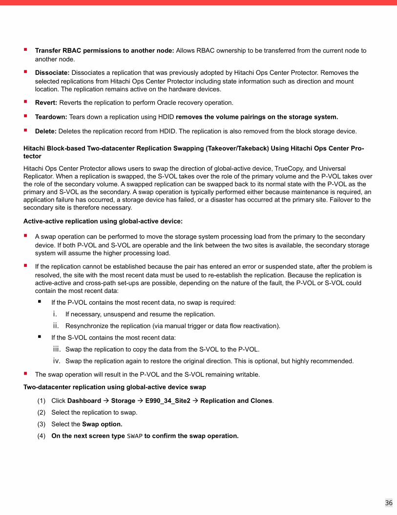
Two-datacenter replication using global-active device swap
(1) Click Dashboard Storage E990_34_Site2 Replication and Clones.
(2) Select the replication to swap.
(3) Select the Swap option.
(4) On the next screen type SWAP to confirm the swap operation.
37
37
Figure 15
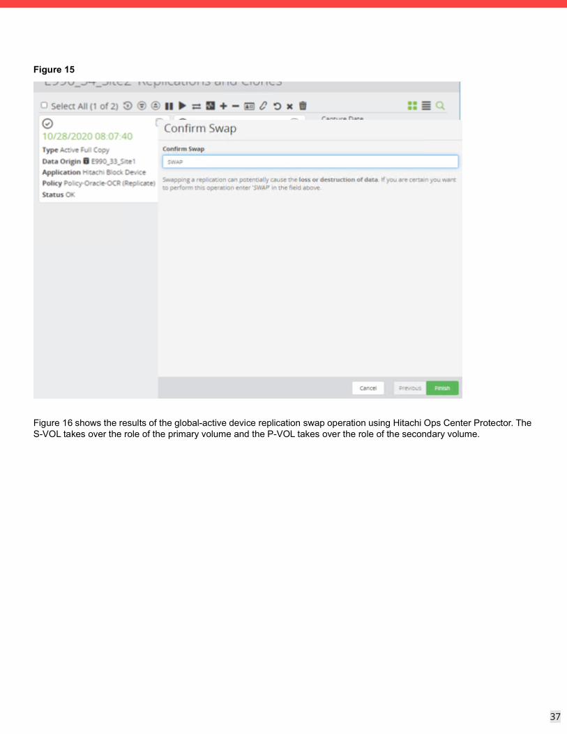
Figure 16 shows the results of the global-active device replication swap operation using Hitachi Ops Center Protector. The S-VOL takes over the role of the primary volume and the P-VOL takes over the role of the secondary volume.
38
38
Figure 16
Perform Backup and Recovery Operations using Hitachi Ops Center Protector and Oracle RMAN SBT IntegrationOracle RMAN (Oracle Recovery Manager) is a backup and recovery tool built in to Oracle databases. Database administrators use RMAN to protect data on Oracle databases by using RMAN capabilities to automate administration of backup strategies and ensure database integrity.
Oracle RMAN handles the underlying maintenance tasks that must be performed before or after any database backup or recovery. The following are some of the RMAN capabilities:
Full/Incremental backups
Transaction logs
Special files (e.g. control files)
Block media recovery
Binary Compression
Encrypted backups
Automated database duplication
Cross-platform data conversion
39
39
Hitachi Ops Center Protector’s RMAN SBT integration allows backup and restore of any data supported by Oracle RMAN for SBT targets. Hitachi Ops Center Protector integrates with Oracle RMAN using the SBT interface, which allows the database administrator to store data in datastores managed by Hitachi Ops Center Protector. The integration leverages Protectors Unified Backup Infrastructure to enable the RMAN backup to both on-site and cloud targets in a flexible and efficient way.
Note — The Oracle RMAN SBT integration supports the full RMAN SBT feature set, including the backup of databases, archive logs, and control files. The only exception to this is proxy backups which are not supported.
To configure the integration in Protector the following configurations are required:
Create a new Oracle Database node and new destination node.
Create a policy using the Oracle RMAN Classification and Access operation. Specify allowed databases and level of access.
Create a dataflow connecting all nodes that should have access to the data.
Create a channel in RMAN to use the SBT channel.
Complete Procedure for Oracle RMAN Integration
Locate the source OS Host node in the Nodes Inventory and verify that it is authorized and online. This node represents the Protector Client installed on the Oracle server.
Create a new Oracle Database node using the Oracle Application Node Wizard and check that the node it is authorized and online. The Oracle Database node type is grouped under Application in the Node Type Wizard. This node will be used in the dataflow to represent the Oracle Database setup to be protected.
Create a new destination node, for example a repository, using the Repository Storage Node Wizard and verify that it is authorized and online.
Destination nodes, like the repository node are grouped under Storage in the Node Type Wizard. You can direct data from multiple nodes to a single repository so there is no need to create a new repository if a suitable one already exists. If a new repository node is being created choose the default Generation 2 type.
To create a node to be used as a backup target, select an existing proxy node, and specify repository directories. Click Finish if values on the summary page are appropriate. Figure 17 shows an example summary page.
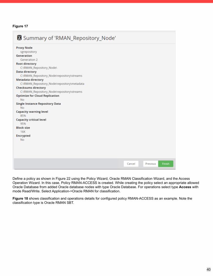
40
40
Figure 17
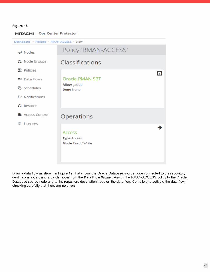
Define a policy as shown in Figure 22 using the Policy Wizard, Oracle RMAN Classification Wizard, and the Access Operation Wizard. In this case, Policy RMAN-ACCESS is created. While creating the policy select an appropriate allowed Oracle Database from added Oracle database nodes with type Oracle Database. For operations select type Access with mode Read/Write. Select Application->Oracle RMAN for classification.
Figure 18 shows classification and operations details for configured policy RMAN-ACCESS as an example. Note the classification type is Oracle RMAN SBT.
41
41
Figure 18
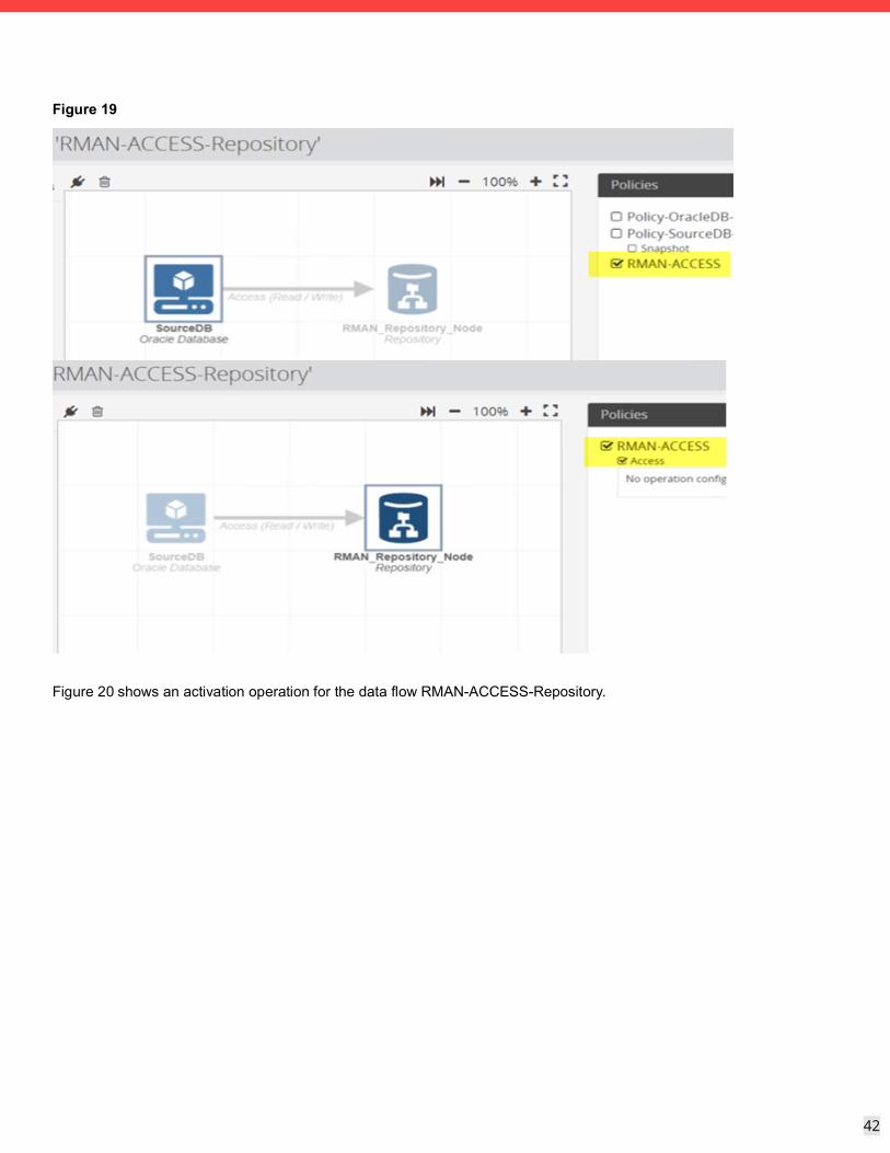
Draw a data flow as shown in Figure 19, that shows the Oracle Database source node connected to the repository destination node using a batch mover from the Data Flow Wizard. Assign the RMAN-ACCESS policy to the Oracle Database source node and to the repository destination node on the data flow. Compile and activate the data flow, checking carefully that there are no errors.
42
42
Figure 19
Figure 20 shows an activation operation for the data flow RMAN-ACCESS-Repository.
43
43
Figure 20
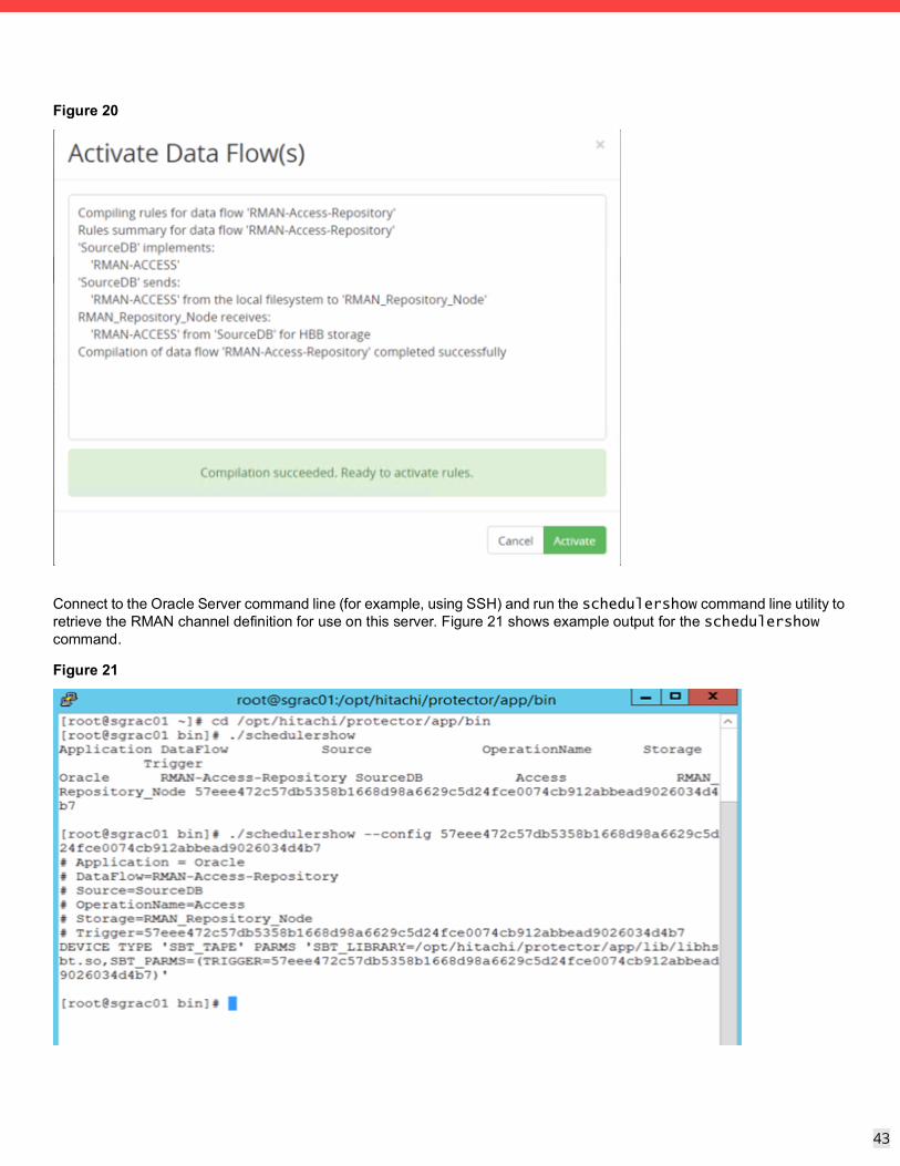
Connect to the Oracle Server command line (for example, using SSH) and run the schedulershow command line utility to retrieve the RMAN channel definition for use on this server. Figure 21 shows example output for the schedulershow command.
Figure 21
44
44
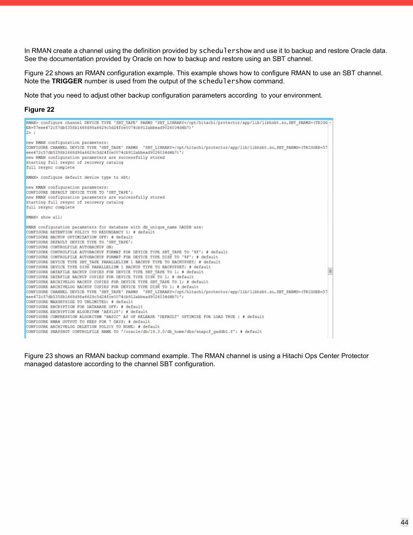
In RMAN create a channel using the definition provided by schedulershow and use it to backup and restore Oracle data. See the documentation provided by Oracle on how to backup and restore using an SBT channel.
Figure 22 shows an RMAN configuration example. This example shows how to configure RMAN to use an SBT channel. Note the TRIGGER number is used from the output of the schedulershow command.
Note that you need to adjust other backup configuration parameters according to your environment.
Figure 22
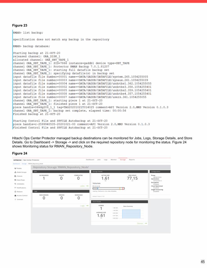
Figure 23 shows an RMAN backup command example. The RMAN channel is using a Hitachi Ops Center Protector managed datastore according to the channel SBT configuration.
45
45
Figure 23
Hitachi Ops Center Protector managed backup destinations can be monitored for Jobs, Logs, Storage Details, and Store Details. Go to Dashboard -> Storage -> and click on the required repository node for monitoring the status. Figure 24 shows Monitoring status for RMAN_Repository_Node.
Figure 24
46
46
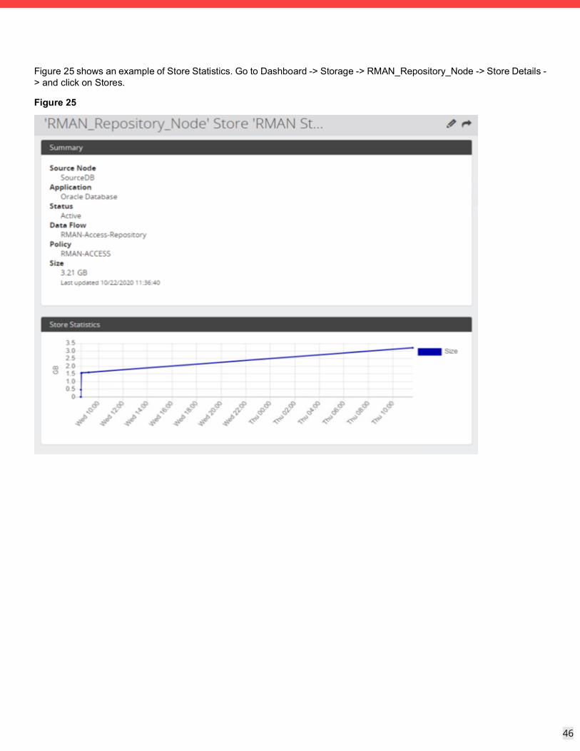
Figure 25 shows an example of Store Statistics. Go to Dashboard -> Storage -> RMAN_Repository_Node -> Store Details -> and click on Stores.
Figure 25

For More InformationHitachi Vantara Global Services offers experienced storage consultants, proven methodologies and a comprehensive services portfolio to assist you in implementing Hitachi products and solutions in your environment. For more information, see the Services website.
Demonstrations and other resources are available for many Hitachi products. To schedule a live demonstration, contact a sales representative or partner. To view on-line informational resources, see the Resources website.
Hitachi Academy is your education destination to acquire valuable knowledge and skills on Hitachi products and solutions. Our Hitachi Certified Professional program establishes your credibility and increases your value in the IT marketplace. For more information, see the Hitachi Vantana Training and Certification website.
For more information about Hitachi products and services, contact your sales representative, partner, or visit the Hitachi Vantara website.

1
Corporate Headquarters2535 Augustine DriveSanta Clara, CA 95054 USAwww.HitachiVantara.com | community.HitachiVantara.com
Regional Contact InformationUSA: 1-800-446-0744Global: 1-858-547-4526HitachiVantara.com/contact
Hitachi Vantara
© Hitachi Vantara LLC, 2021. All rights reserved. HITACHI is a trademark or registered trademark of Hitachi, Ltd. VSP is a trademark or registered trademark of Hitachi Vantara LLC. Microsoft, Windows Server, and Microsoft Office are trademarks or registered trademarks of Microsoft Corporation. All other trademarks, service marks, and company names are properties of their respective owners.
Notice: This document is for informational purposes only, and does not set forth any warranty, expressed or implied, concerning any equipment or service offered or to be offered by Hitachi Vantara LLC.
MK-SL-218-00, February 2021