Embed Size (px)
Citation preview
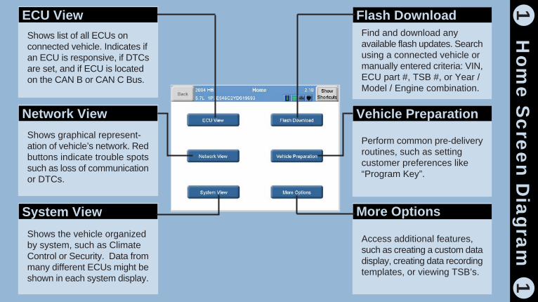
Home Screen Diagram
Shortcuts Toolbar Diagram
Network View Diagram
Read and Clear DTCs
View and Graph Data
Start an Actuator
Set Customer Preferences
Download Flash Updates
Install Flash Updates
Create a Custom Display
Cable Connections Diagram
Update Tool
Calibrate Touch Screen
Care of the StarSCAN Tool
Ho
me
Sc
ree
n D
iag
ram
11
Shows list of all ECUs onconnected vehicle. Indicates ifan ECU is responsive, if DTCsare set, and if ECU is locatedon the CAN B or CAN C Bus.
ECU View
Shows graphical represent-ation of vehicle’s network. Redbuttons indicate trouble spotssuch as loss of communicationor DTCs.
Network View
Shows the vehicle organizedby system, such as ClimateControl or Security. Data frommany different ECUs might beshown in each system display.
System View
Find and download anyavailable flash updates. Searchusing a connected vehicle ormanually entered criteria: VIN,ECU part #, TSB #, or Year /Model / Engine combination.
Flash Download
Perform common pre-deliveryroutines, such as settingcustomer preferences like“Program Key”.
Vehicle Preparation
Access additional features,such as creating a custom datadisplay, creating data recordingtemplates, or viewing TSB’s.
More Options

Print paper copy ofcurrent screen
Print ScreenS
ho
rtcu
ts Ba
r Dia
gra
m2
2Display Home screen
Home
Adjust tool settings
Tool Menu
Closes the Shortcutstoolbar
Hide Shortcuts
Download and installsoftware updates
Update ToolView electronic usermanual
Help

Touch to display StarSCANstatus. Turns red to indicatea serious malfunction in theStarSCAN tool itself.
StarSCAN
Touch to display vehiclecommunication status. Turnsred to indicate CAN electricalfaults such as short to grounds,power, and opens.
Diag CAN C
Touch to display a list of theconnected vehicle’s ECUs andother configuration information.Turns red to indicate thatStarSCAN can’t communcatewith the gateway.
Gateway
Touch to display CAN B orCAN C Bus status. Turns redto indicate electrical faults suchas short to grounds, power,and opens.
CAN B / CAN C Bus
Touch to display a list ofproblem ECUs. Turns red toindicate problem ECUs suchas non-responsive ECUs orECUs with DTCs set.
Powertrain / Chassis
Touch to display a list ofproblem ECUs. Turns red toindicate problem ECUs suchas non-responsive ECUs orECUs with DTCs set.
Body / Interior / Safety
Touch to display detailednetwork communication DTC’sreport.
Advanced
Ne
two
rk V
iew
Dia
gra
m3
3
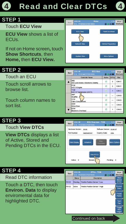
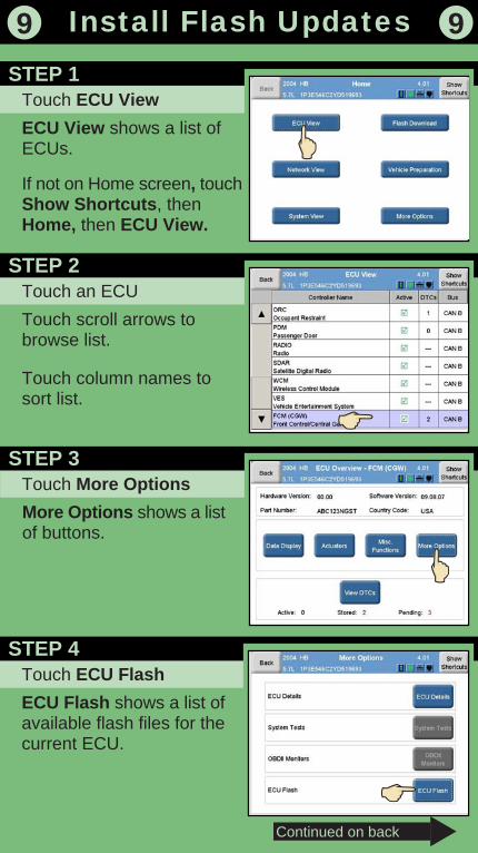
ECU View shows a list ofECUs.
If not on Home screen, touchShow Shortcuts, thenHome, then ECU View.
Touch ECU View
Read and Clear DTCs4 4
STEP 1
Touch an ECU
Touch scroll arrows tobrowse list.
Touch column names tosort list.
STEP 2
Touch View DTCs
View DTCs displays a listof Active, Stored andPending DTCs in the ECU.
STEP 3
Read DTC information
Touch a DTC, then touchEnviron. Data to displayenviromental data forhighlighted DTC.
STEP 4
Continued on back
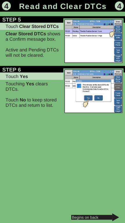
Touch Clear Stored DTCs
Read and Clear DTCs
Clear Stored DTCs showsa Confirm message box.
Active and Pending DTCswill not be cleared.
4 4
STEP 5
Touch Yes
Touching Yes clearsDTCs.
Touch No to keep storedDTCs and return to list.
STEP 6
Begins on back

Data Display shows a listof status and sensor valuesfor the selected ECU.
Most recent DTC set is atbottom of screen.
Touch ECU View
ECU View shows a list ofECUs.
If not on Home screen, touchShow Shortcuts, thenHome, then ECU View.
5 5
STEP 1
Touch an ECU
Touch scroll arrows tobrowse list.
Touch column names tosort list.
STEP 2
Touch Data DisplaySTEP 3
Read data
Touch scroll arrows tobrowse list.
Touch column names tosort list.
STEP 4
Continued on back
View and Graph Data
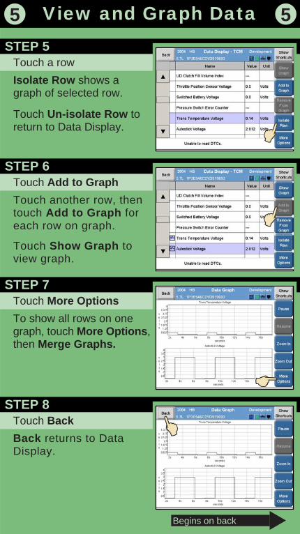
Touch a row
Isolate Row shows agraph of selected row.
Touch Un-isolate Row toreturn to Data Display.
5 5
STEP 5
Touch Add to Graph
Touch another row, thentouch Add to Graph foreach row on graph.
Touch Show Graph toview graph.
STEP 6
Begins on back
View and Graph Data
Touch More Options
To show all rows on onegraph, touch More Options,then Merge Graphs.
STEP 7
Touch Back
Back returns to DataDisplay.
STEP 8
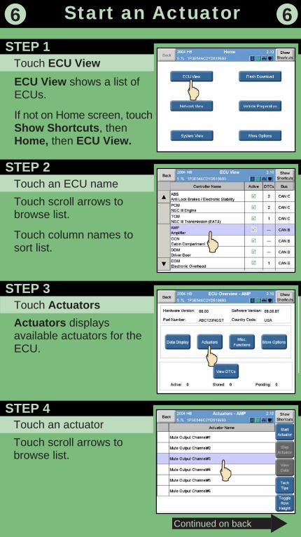
Touch Actuators
Actuators displaysavailable actuators for theECU.
Touch an ECU name
Touch scroll arrows tobrowse list.
Touch column names tosort list.
ECU View shows a list ofECUs.
If not on Home screen, touchShow Shortcuts, thenHome, then ECU View.
Touch ECU View
6 6
STEP 1
STEP 2
STEP 3
Touch an actuator
Touch scroll arrows tobrowse list.
STEP 4
Continued on back
Start an Actuator
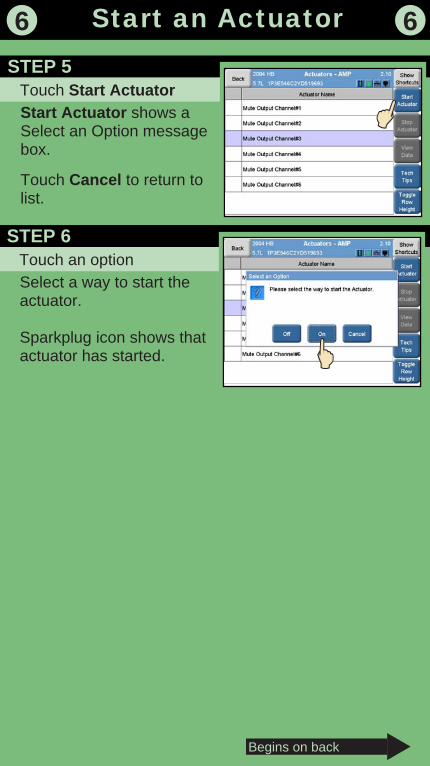
Start Actuator shows aSelect an Option messagebox.
Touch Cancel to return tolist.
Touch Start Actuator
6 6
STEP 5
Begins on back
Start an Actuator
Select a way to start theactuator.
Sparkplug icon shows thatactuator has started.
Touch an optionSTEP 6
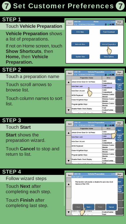
Touch scroll arrows tobrowse list.
Touch column names to sortlist.
Touch Vehicle Preparation
Vehicle Preparation showsa list of preparations.If not on Home screen, touchShow Shortcuts, thenHome, then VehiclePreparation.
7 7
STEP 1
Touch a preparation nameSTEP 2
Touch Start
Start shows thepreparation wizard.
Touch Cancel to stop andreturn to list.
STEP 3
Set Customer Preferences
Follow wizard steps
Touch Next aftercompleting each step.
Touch Finish aftercompleting last step.
STEP 4

Wizard downloads updateand stores it on USB device.
Click Next after completingeach step. Touch Finish aftercompleting last step.
Obtain Update Kit
The StarSCAN update kitcontains a CD-ROM, a USBstorage device, and a USBadapter. You can use the kitwith TechCONNECT or a PC.
8 8
STEP 1
Insert CD-ROM
Insert CD-ROM intoTechCONNECT or PC.Software starts automatically.
Click Controller Flash.
STEP 2
Follow wizard stepsSTEP 3
Connect USB deviceRemove USB device fromTechCONNECT / PC.
With tool powered off,connect USB device toStarSCAN tool using suppliedadapter.
STEP 4
Continued on back
Download Flash Updates
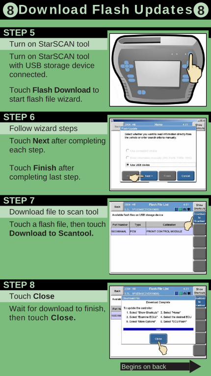
Turn on StarSCAN tool
Turn on StarSCAN toolwith USB storage deviceconnected.
Touch Flash Download tostart flash file wizard.
8 8
STEP 5
Follow wizard steps
Touch Next after completingeach step.
Touch Finish aftercompleting last step.
STEP 6
Begins on back
Download Flash Updates
Download file to scan tool
Touch a flash file, then touchDownload to Scantool.
STEP 7
Touch Close
Wait for download to finish,then touch Close.
STEP 8
More Options shows a listof buttons.
Touch ECU View
ECU View shows a list ofECUs.
If not on Home screen, touchShow Shortcuts, thenHome, then ECU View.
9 9
STEP 1
Touch an ECU
Touch scroll arrows tobrowse list.
Touch column names tosort list.
STEP 2
Touch More OptionsSTEP 3
Touch ECU Flash
ECU Flash shows a list ofavailable flash files for thecurrent ECU.
STEP 4
Continued on back
Install Flash Updates
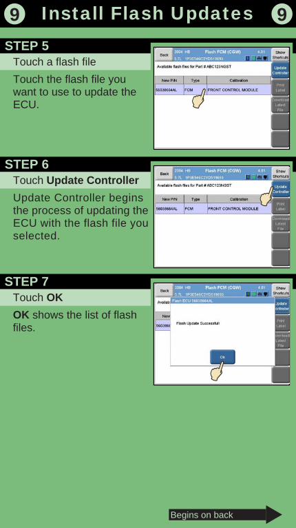
Touch a flash file
Touch the flash file youwant to use to update theECU.
9 9
STEP 5
Touch Update Controller
Update Controller beginsthe process of updating theECU with the flash file youselected.
STEP 6
Begins on back
Install Flash Updates
Touch OK
OK shows the list of flashfiles.
STEP 7

More Options shows a listof buttons.
If not on Home screen,touch Show Shortcuts,Home, then More Options.
Touch More Options
10 10
STEP 1
Touch Custom Display
Custom Display shows alist of custom displaychoices.
Touch column names tosort list.
STEP 2
Touch Create New Display
Create New Displaydisplays a list of ECUs.
STEP 3
Touch an ECU
ECU shows a list of DDEs(data elements) within thatECU.
Touch column names tosort list.
STEP 4
Continued on back
Create a Custom Display
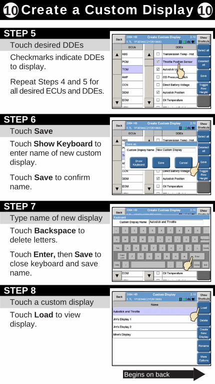
Checkmarks indicate DDEsto display.
Repeat Steps 4 and 5 forall desired ECUs and DDEs.
Touch desired DDEs
10 10
STEP 5
Touch Save
Touch Show Keyboard toenter name of new customdisplay.
Touch Save to confirmname.
STEP 6
Type name of new display
Touch Backspace todelete letters.
Touch Enter, then Save toclose keyboard and savename.
STEP 7
Begins on back
Create a Custom Display
Touch a custom display
Touch Load to viewdisplay.
STEP 8
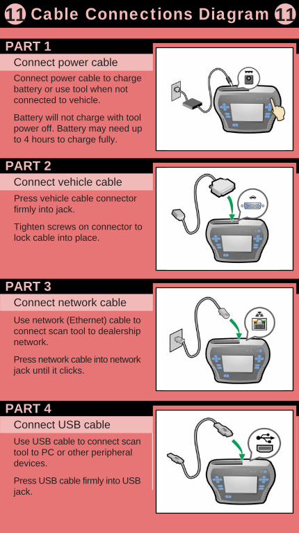
Press vehicle cable connectorfirmly into jack.
Tighten screws on connector tolock cable into place.
Connect power cableConnect power cable to chargebattery or use tool when notconnected to vehicle.
Battery will not charge with toolpower off. Battery may need upto 4 hours to charge fully.
11 11
PART 1
Connect vehicle cablePART 2
Connect network cableUse network (Ethernet) cable toconnect scan tool to dealershipnetwork.
Press network cable into networkjack until it clicks.
PART 3
Cable Connections Diagram
Connect USB cableUse USB cable to connect scantool to PC or other peripheraldevices.
Press USB cable firmly into USBjack.
PART 4
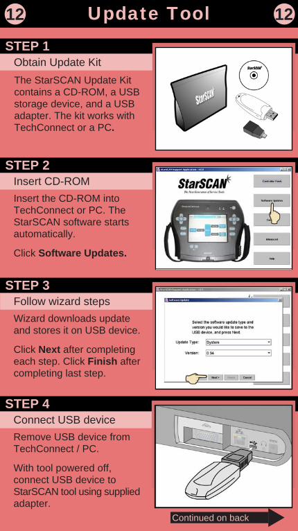
The StarSCAN Update Kitcontains a CD-ROM, a USBstorage device, and a USBadapter. The kit works withTechConnect or a PC.
Obtain Update Kit
12 12
STEP 1
Insert CD-ROMInsert the CD-ROM intoTechConnect or PC. TheStarSCAN software startsautomatically.
Click Software Updates.
STEP 2
Follow wizard stepsWizard downloads updateand stores it on USB device.
Click Next after completingeach step. Click Finish aftercompleting last step.
STEP 3
Connect USB deviceRemove USB device fromTechConnect / PC.
With tool powered off,connect USB device toStarSCAN tool using suppliedadapter.
STEP 4
Continued on back
Update Tool
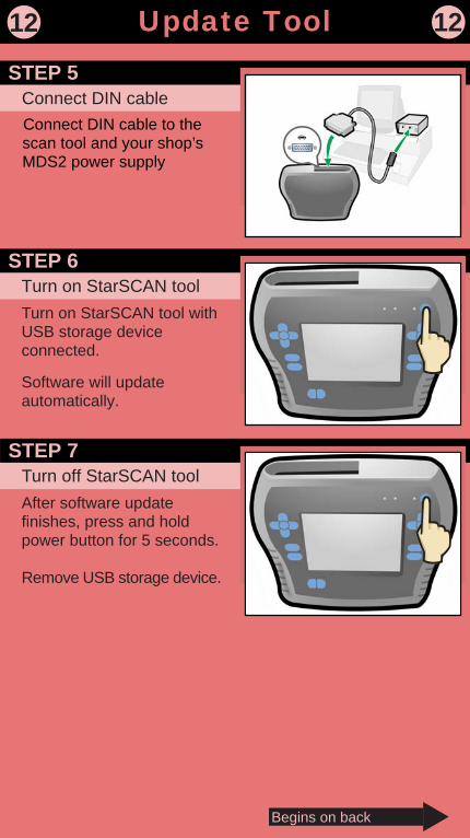
Connect DIN cable to thescan tool and your shop’sMDS2 power supply
Connect DIN cable
12 12
STEP 5
Turn on StarSCAN toolTurn on StarSCAN tool withUSB storage deviceconnected.
Software will updateautomatically.
STEP 6
Begins on back
Update Tool
Turn off StarSCAN toolAfter software updatefinishes, press and holdpower button for 5 seconds.
Remove USB storage device.
STEP 7
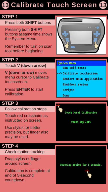
Pressing both SHIFTbuttons at same time showsthe System Menu.
Remember to turn on scantool before beginning.
Press both SHIFT buttons
13 13
STEP 1
Touch V (down arrow)
V (down arrow) movesmenu cursor to Calibratetouchscreen.
Press ENTER to startcalibration.
STEP 2
Follow calibration steps
Touch red crosshairs asinstructed on screen.
Use stylus for betterprecision, but finger alsomay be used.
STEP 3
Check motion tracking
Drag stylus or fingeraround screen.
Calibration is complete atend of 5-secondcountdown.
STEP 4
Calibrate Touch Screen

Follow standard guidelinesThe StarSCAN tool has been designed to operate in a typical shopenvironment, but treating it with care will ensure its long life.
Clean the tool regularly and avoid long-term contact with harsh materialsor temperatures.
Avoid using StarSCAN tool for long periods in temperatures above 104F (40 C).
14 14
PART 1
Care of the touch screenPART 2
Care of the enclosureUse a clean (damp) non-abrasive cloth towel and a mild cleaning solutionto clean the enclosure’s surface.
Apply cleaning solutions to the towel rather than directly to the toolenclosure.
PART 3
Care of the StarSCAN Tool
Cautions and warningsDo not allow the StarSCAN tool to come into contact with strong solventssuch as throttle body cleaner, brake cleaner, contact cleaner, xylene,or acetone.
Avoid exposure to brake fluid, antifreeze, and petroleum products. Ifexposed, remove all traces of the chemical as described above.
Avoid contact of the tool’s case with high temperatures. version 1.0 11/06/03
PART 4
Use a clean (damp) non-abrasive cloth towel and glass cleaner (suchas Mopar Window Cleaner) to clean the touchscreen surface whennecessary.
Apply the cleaning solution to the towel rather than directly to thetouchscreen.