Embed Size (px)
Citation preview
How to Trap:Steam Distribution
System
North America • Latin America • India • Europe / Middle East / Africa • China • Pacific Rimarmstronginternational.com
Designs, materials, weights and performance ratings are approximate and subject to change without notice. Visit armstronginternational.com for up-to-date information.2
IMPORTANT: This section is intended to summarize general principles of installation and operation of steam traps, as outlined above. Actual installation and operation of steam trapping equipment should be performed only by experienced personnel. Selection or installation should always be accompanied by competent technical assistance or advice. This data should never be used as a substitute for such technical advice or assistance. We encourage you to contact Armstrong or its local representative for further details.
Bringing Energy Down to Earth
Say energy. Think environment. And vice versa.Any company that is energy conscious is also environmentally conscious. Less energy consumed means less waste, fewer emissions and a healthier environment.
In short, bringing energy and environment together lowers the cost industry must pay for both. By helping companies manage energy, Armstrong products and services are also helping to protect the environment.
Armstrong has been sharing know-how since we invented the energy-efficient inverted bucket steam trap in 1911. In the years since, customers’ savings have proven again and again that knowledge not shared is energy wasted.
Armstrong’s developments and improvements in steam trap design and function have led to countless savings in energy, time and money. This section has grown out of our decades of sharing and expanding what we’ve learned. It deals with the operating principles of steam traps and outlines their specific applications to a wide variety of products and industries. You’ll find it a useful complement to other Armstrong literature and the Armstrong Steam-A-ware™ software program for sizing and selecting steam traps, pressure reducing valves and water heaters, which can be requested through Armstrong’s Web site, armstronginternational.com.
This section also includes Recommendation Charts that summarize our findings on which type of trap will give optimum performance in a given situation and why.
North America • Latin America • India • Europe / Middle East / Africa • China • Pacific Rimarmstronginternational.com
Designs, materials, weights and performance ratings are approximate and subject to change without notice. Visit armstronginternational.com for up-to-date information.3
Chart 3-1. Recommendation Chart (See chart below for “Feature Code” References.)
Equipment Being Trapped 1st Choice and Feature
Code Alternate Choice
Jacketed Kettles Gravity Drain
IBLV B, C, E, K, N F&T or Thermostatic
Jacketed Kettles Syphon Drain
DC B, C, E, G, H, K, N, P IBLV
Chart 3-2. How Various Types of Steam Traps Meet Specific Operating Requirements Feature
CodeCharacteristic IB BM F&T Disc
Thermostatic Wafer
DC Orifice
A Method of Operation (1) Intermittent (2) Intermittent Continuous Intermittent (2) Intermittent Continuous Continuous
B Energy Conservation (Time in Service) Excellent Excellent Good Poor Fair (3) Excellent Poor
C Resistance to Wear Excellent Excellent Good Poor Fair Excellent Poor
D Corrosion Resistance Excellent Excellent Good Excellent Good Excellent Good
E Resistance to Hydraulic Shock Excellent Excellent Poor Excellent (4) Poor Excellent Good
F Vents Air and CO2 at Steam Temperature Yes No No No No Yes Poor
G Ability to Vent Air at Very Low Pressure (1/4 psig) Poor (5) NR Excellent (5) NR Good Excellent Poor
H Ability to Handle Start-Up Air Loads Fair Excellent Excellent Poor Excellent Excellent Poor
I Operation Against Back Pressure Excellent Excellent Excellent Poor Excellent Excellent Poor
J Resistance to Damage From Freezing (6) Good Good Poor Good Good Good Excellent
K Ability to Purge System Excellent Good Fair Excellent Good Excellent Poor
L Performance on Very Light Loads Excellent Excellent Excellent Poor Excellent Excellent Poor
M Responsiveness to Slugs of Condensate Immediate Delayed Immediate Delayed Delayed Immediate Poor
N Ability to Handle Dirt Excellent Fair Poor Poor Fair Excellent Poor
O Comparative Physical Size (7) Large Small Large Small Small Large Small
P Ability to Handle“Flash Steam” Fair Poor Poor Poor Poor Excellent Poor
Q Mechanical Failure (Open or Closed) Open Open Closed (8) Open (9) Open NA
Instructions for Using the Recommendation Charts
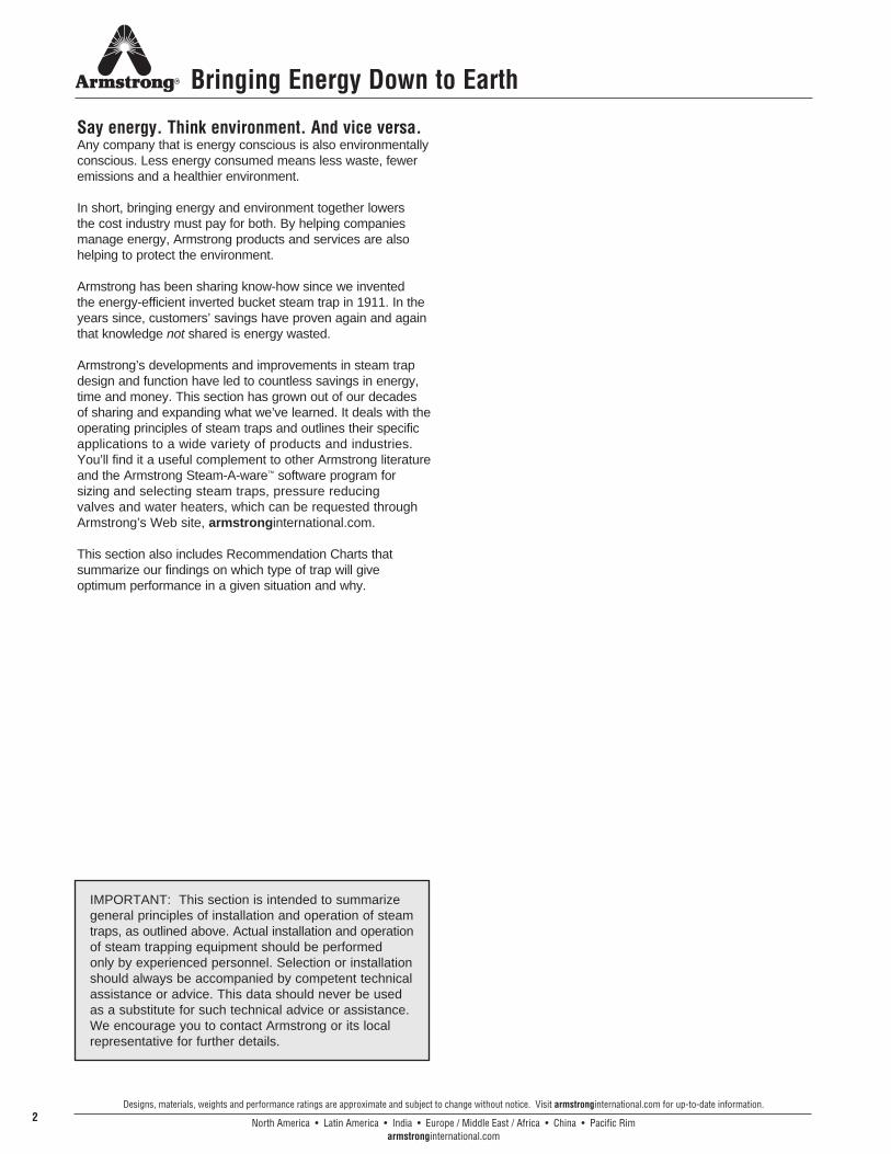
A quick reference Recommendation Chart appears throughout the “HOW TO TRAP” brochures (857-EN - 868-EN).
A feature code system (ranging from A to Q) supplies you with “at-a-glance” information.
The chart covers the type of steam traps and the major advantages that Armstrong feels are superior for each particular application.
For example, assume you are looking for information concerning the proper trap to use on a gravity drained jacketed kettle. You would:
1. Turn to the “How to Trap Jacketed Kettles” brochure, 864-EN, and look in the lower right-hand corner of page 10. The Recommendation Chart located there is reprinted below for your convenience. (Each section has a Recommendation Chart.)
2. Find “Jacketed Kettles, Gravity Drain” in the first column under “Equipment Being Trapped” and read to the right for Armstrong’s “1st Choice and Feature Code.” In this case, the first choice is an IBLV and the feature code letters B, C, E, K, N are listed.
3. Now refer to Chart 3-2 below, titled “How Various Types of Steam Traps Meet Specific Operating Requirements” and read down the extreme left-hand column to each of the letters B, C, E, K, N. The letter “B,” for example, refers to the trap’s ability to provide energy-conserving operation.
4. Follow the line for “B” to the right until you reach the column that corresponds to our first choice, in this case the inverted bucket. Based on tests and actual operating conditions, the energy-conserving performance of the inverted bucket steam trap has been rated “Excellent.” Follow this same procedure for the remaining letters.
Abbreviations IB Inverted Bucket Trap IBLV Inverted Bucket Large Vent BM Bimetallic Trap F&T Float and Thermostatic Trap CD Controlled Disc Trap DC Automatic Differential Condensate Controller CV Check Valve T Thermic Bucket PRV Pressure Reducing Valve
(1) Drainage of condensate is continuous. Discharge is intermittent. (2) Can be continuous on low load. (3) Excellent when “secondary steam” is utilized. (4) Bimetallic and wafer traps – good. (5) Not recommended for low pressure operations.
(6) Cast iron traps not recommended.(7) In welded stainless steel construction – medium.(8) Can fail closed due to dirt.(9) Can fail either open or closed, depending upon the design of the bellows.
North America • Latin America • India • Europe / Middle East / Africa • China • Pacific Rimarmstronginternational.com
Designs, materials, weights and performance ratings are approximate and subject to change without notice. Visit armstronginternational.com for up-to-date information.4
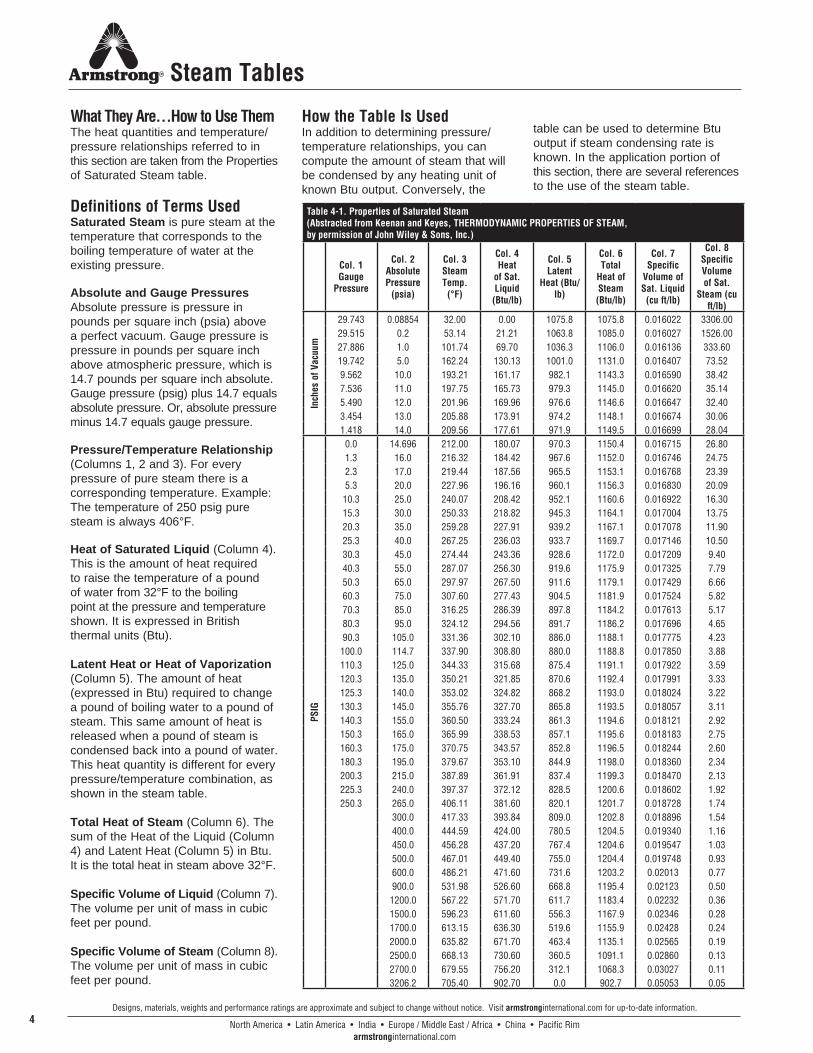
What They Are…How to Use ThemThe heat quantities and temperature/ pressure relationships referred to in this section are taken from the Properties of Saturated Steam table.
Definitions of Terms UsedSaturated Steam is pure steam at the temperature that corresponds to the boiling temperature of water at the existing pressure.
Absolute and Gauge Pressures Absolute pressure is pressure in pounds per square inch (psia) above a perfect vacuum. Gauge pressure is pressure in pounds per square inch above atmospheric pressure, which is 14.7 pounds per square inch absolute. Gauge pressure (psig) plus 14.7 equals absolute pressure. Or, absolute pressure minus 14.7 equals gauge pressure.
Pressure/Temperature Relationship (Columns 1, 2 and 3). For every pressure of pure steam there is a corresponding temperature. Example: The temperature of 250 psig pure steam is always 406°F.
Heat of Saturated Liquid (Column 4). This is the amount of heat required to raise the temperature of a pound of water from 32°F to the boiling point at the pressure and temperature shown. It is expressed in British thermal units (Btu).
Latent Heat or Heat of Vaporization (Column 5). The amount of heat (expressed in Btu) required to change a pound of boiling water to a pound of steam. This same amount of heat is released when a pound of steam is condensed back into a pound of water. This heat quantity is different for every pressure/temperature combination, as shown in the steam table.
Total Heat of Steam (Column 6). The sum of the Heat of the Liquid (Column 4) and Latent Heat (Column 5) in Btu. It is the total heat in steam above 32°F.
Specific Volume of Liquid (Column 7). The volume per unit of mass in cubic feet per pound.
Specific Volume of Steam (Column 8). The volume per unit of mass in cubic feet per pound.
How the Table Is UsedIn addition to determining pressure/ temperature relationships, you can compute the amount of steam that will be condensed by any heating unit of known Btu output. Conversely, the
table can be used to determine Btu output if steam condensing rate is known. In the application portion of this section, there are several references to the use of the steam table.
Table 4-1. Properties of Saturated Steam (Abstracted from Keenan and Keyes, THERMODYNAMIC PROPERTIES OF STEAM, by permission of John Wiley & Sons, Inc.)
Col. 1 Gauge
Pressure
Col. 2 Absolute Pressure
(psia)
Col. 3 Steam Temp.
(°F)
Col. 4 Heat
of Sat. Liquid
(Btu/lb)
Col. 5 Latent
Heat (Btu/lb)
Col. 6 Total
Heat of Steam (Btu/lb)
Col. 7 Specific
Volume of Sat. Liquid
(cu ft/lb)
Col. 8 Specific Volume of Sat.
Steam (cu ft/lb)
Inch
es o
f Vac
uum
29.743 0.08854 32.00 0.00 1075.8 1075.8 0.016022 3306.0029.515 0.2 53.14 21.21 1063.8 1085.0 0.016027 1526.0027.886 1.0 101.74 69.70 1036.3 1106.0 0.016136 333.6019.742 5.0 162.24 130.13 1001.0 1131.0 0.016407 73.529.562 10.0 193.21 161.17 982.1 1143.3 0.016590 38.427.536 11.0 197.75 165.73 979.3 1145.0 0.016620 35.145.490 12.0 201.96 169.96 976.6 1146.6 0.016647 32.403.454 13.0 205.88 173.91 974.2 1148.1 0.016674 30.061.418 14.0 209.56 177.61 971.9 1149.5 0.016699 28.04
PSIG
0.0 14.696 212.00 180.07 970.3 1150.4 0.016715 26.801.3 16.0 216.32 184.42 967.6 1152.0 0.016746 24.752.3 17.0 219.44 187.56 965.5 1153.1 0.016768 23.395.3 20.0 227.96 196.16 960.1 1156.3 0.016830 20.09
10.3 25.0 240.07 208.42 952.1 1160.6 0.016922 16.3015.3 30.0 250.33 218.82 945.3 1164.1 0.017004 13.7520.3 35.0 259.28 227.91 939.2 1167.1 0.017078 11.9025.3 40.0 267.25 236.03 933.7 1169.7 0.017146 10.5030.3 45.0 274.44 243.36 928.6 1172.0 0.017209 9.4040.3 55.0 287.07 256.30 919.6 1175.9 0.017325 7.7950.3 65.0 297.97 267.50 911.6 1179.1 0.017429 6.6660.3 75.0 307.60 277.43 904.5 1181.9 0.017524 5.8270.3 85.0 316.25 286.39 897.8 1184.2 0.017613 5.1780.3 95.0 324.12 294.56 891.7 1186.2 0.017696 4.6590.3 105.0 331.36 302.10 886.0 1188.1 0.017775 4.23100.0 114.7 337.90 308.80 880.0 1188.8 0.017850 3.88110.3 125.0 344.33 315.68 875.4 1191.1 0.017922 3.59120.3 135.0 350.21 321.85 870.6 1192.4 0.017991 3.33125.3 140.0 353.02 324.82 868.2 1193.0 0.018024 3.22130.3 145.0 355.76 327.70 865.8 1193.5 0.018057 3.11140.3 155.0 360.50 333.24 861.3 1194.6 0.018121 2.92150.3 165.0 365.99 338.53 857.1 1195.6 0.018183 2.75160.3 175.0 370.75 343.57 852.8 1196.5 0.018244 2.60180.3 195.0 379.67 353.10 844.9 1198.0 0.018360 2.34200.3 215.0 387.89 361.91 837.4 1199.3 0.018470 2.13225.3 240.0 397.37 372.12 828.5 1200.6 0.018602 1.92250.3 265.0 406.11 381.60 820.1 1201.7 0.018728 1.74
300.0 417.33 393.84 809.0 1202.8 0.018896 1.54400.0 444.59 424.00 780.5 1204.5 0.019340 1.16450.0 456.28 437.20 767.4 1204.6 0.019547 1.03500.0 467.01 449.40 755.0 1204.4 0.019748 0.93600.0 486.21 471.60 731.6 1203.2 0.02013 0.77900.0 531.98 526.60 668.8 1195.4 0.02123 0.50
1200.0 567.22 571.70 611.7 1183.4 0.02232 0.361500.0 596.23 611.60 556.3 1167.9 0.02346 0.281700.0 613.15 636.30 519.6 1155.9 0.02428 0.242000.0 635.82 671.70 463.4 1135.1 0.02565 0.192500.0 668.13 730.60 360.5 1091.1 0.02860 0.132700.0 679.55 756.20 312.1 1068.3 0.03027 0.113206.2 705.40 902.70 0.0 902.7 0.05053 0.05
Steam Tables
North America • Latin America • India • Europe / Middle East / Africa • China • Pacific Rimarmstronginternational.com
Designs, materials, weights and performance ratings are approximate and subject to change without notice. Visit armstronginternational.com for up-to-date information.5
Steam Tables
400
300
200
100
0 100 200 300 400
PRESSURE AT WHICH CONDENSATEIS FORMED—LBS/SQ IN
CU
FT
FL
AS
H S
TE
AM
PE
R C
U F
T O
F C
ON
DE
NS
AT
E
30
0
5
10
15
20
25
– 20 300250200150100500
PE
RC
EN
TAG
E O
F F
LA
SH
ST
EA
M
PSI FROM WHICH CONDENSATE IS DISCHARGED
CURVEBACK PRESS.
LBS/SQ IN
ABCDEFG
105010203040
––
B
C
DE
F
A
G
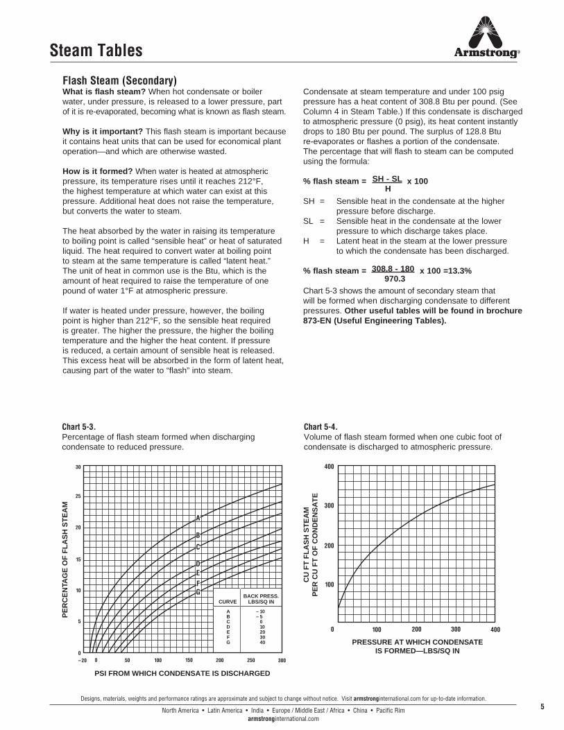
Flash Steam (Secondary)What is flash steam? When hot condensate or boiler water, under pressure, is released to a lower pressure, part of it is re-evaporated, becoming what is known as flash steam.
Why is it important? This flash steam is important because it contains heat units that can be used for economical plant operation—and which are otherwise wasted.
How is it formed? When water is heated at atmospheric pressure, its temperature rises until it reaches 212°F, the highest temperature at which water can exist at this pressure. Additional heat does not raise the temperature, but converts the water to steam.
The heat absorbed by the water in raising its temperature to boiling point is called “sensible heat” or heat of saturated liquid. The heat required to convert water at boiling point to steam at the same temperature is called “latent heat.” The unit of heat in common use is the Btu, which is the amount of heat required to raise the temperature of one pound of water 1°F at atmospheric pressure.
If water is heated under pressure, however, the boiling point is higher than 212°F, so the sensible heat required is greater. The higher the pressure, the higher the boiling temperature and the higher the heat content. If pressure is reduced, a certain amount of sensible heat is released. This excess heat will be absorbed in the form of latent heat, causing part of the water to “flash” into steam.
Condensate at steam temperature and under 100 psig pressure has a heat content of 308.8 Btu per pound. (See Column 4 in Steam Table.) If this condensate is discharged to atmospheric pressure (0 psig), its heat content instantly drops to 180 Btu per pound. The surplus of 128.8 Btu re-evaporates or flashes a portion of the condensate. The percentage that will flash to steam can be computed using the formula:
% flash steam = x 100 SH = Sensible heat in the condensate at the higher pressure before discharge.SL = Sensible heat in the condensate at the lower pressure to which discharge takes place.H = Latent heat in the steam at the lower pressure to which the condensate has been discharged.
% flash steam = x 100 =13.3%
Chart 5-3 shows the amount of secondary steam that will be formed when discharging condensate to different pressures. Other useful tables will be found in brochure 873-EN (Useful Engineering Tables).
SH - SL H
308.8 - 180 970.3
Chart 5-3.Percentage of flash steam formed when discharging condensate to reduced pressure.
Chart 5-4.Volume of flash steam formed when one cubic foot of condensate is discharged to atmospheric pressure.
North America • Latin America • India • Europe / Middle East / Africa • China • Pacific Rimarmstronginternational.com
Designs, materials, weights and performance ratings are approximate and subject to change without notice. Visit armstronginternational.com for up-to-date information.6
Steam…Basic Concepts
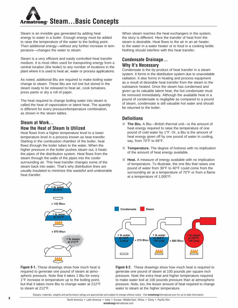
Steam is an invisible gas generated by adding heat energy to water in a boiler. Enough energy must be added to raise the temperature of the water to the boiling point. Then additional energy—without any further increase in tem-perature—changes the water to steam.
Steam is a very efficient and easily controlled heat transfer medium. It is most often used for transporting energy from a central location (the boiler) to any number of locations in the plant where it is used to heat air, water or process applications.
As noted, additional Btu are required to make boiling water change to steam. These Btu are not lost but stored in the steam ready to be released to heat air, cook tomatoes, press pants or dry a roll of paper.
The heat required to change boiling water into steam is called the heat of vaporization or latent heat. The quantity is different for every pressure/temperature combination, as shown in the steam tables.
Steam at Work…How the Heat of Steam Is UtilizedHeat flows from a higher temperature level to a lower temperature level in a process known as heat transfer. Starting in the combustion chamber of the boiler, heat flows through the boiler tubes to the water. When the higher pressure in the boiler pushes steam out, it heats the pipes of the distribution system. Heat flows from the steam through the walls of the pipes into the cooler surrounding air. This heat transfer changes some of the steam back into water. That’s why distribution lines are usually insulated to minimize this wasteful and undesirable heat transfer.
When steam reaches the heat exchangers in the system, the story is different. Here the transfer of heat from the steam is desirable. Heat flows to the air in an air heater, to the water in a water heater or to food in a cooking kettle. Nothing should interfere with this heat transfer.
Condensate Drainage…Why It’s NecessaryCondensate is the by-product of heat transfer in a steam system. It forms in the distribution system due to unavoidable radiation. It also forms in heating and process equipment as a result of desirable heat transfer from the steam to the substance heated. Once the steam has condensed and given up its valuable latent heat, the hot condensate must be removed immediately. Although the available heat in a pound of condensate is negligible as compared to a pound of steam, condensate is still valuable hot water and should be returned to the boiler.
Definitionsn The Btu. A Btu—British thermal unit—is the amount of
heat energy required to raise the temperature of one pound of cold water by 1°F. Or, a Btu is the amount of heat energy given off by one pound of water in cooling, say, from 70°F to 69°F.
n Temperature. The degree of hotness with no implication of the amount of heat energy available.
n Heat. A measure of energy available with no implication of temperature. To illustrate, the one Btu that raises one pound of water from 39°F to 40°F could come from the surrounding air at a temperature of 70°F or from a flame at a temperature of 1,000°F.
Figure 6-1. These drawings show how much heat is required to generate one pound of steam at atmo-spheric pressure. Note that it takes 1 Btu for every 1°F increase in temperature up to the boiling point, but that it takes more Btu to change water at 212°F to steam at 212°F.
Figure 6-2. These drawings show how much heat is required to generate one pound of steam at 100 pounds per square inch pressure. Note the extra heat and higher temperature required to make water boil at 100 pounds pressure than at atmospheric pressure. Note, too, the lesser amount of heat required to change water to steam at the higher temperature.
North America • Latin America • India • Europe / Middle East / Africa • China • Pacific Rimarmstronginternational.com
Designs, materials, weights and performance ratings are approximate and subject to change without notice. Visit armstronginternational.com for up-to-date information.7
Steam…Basic Concepts
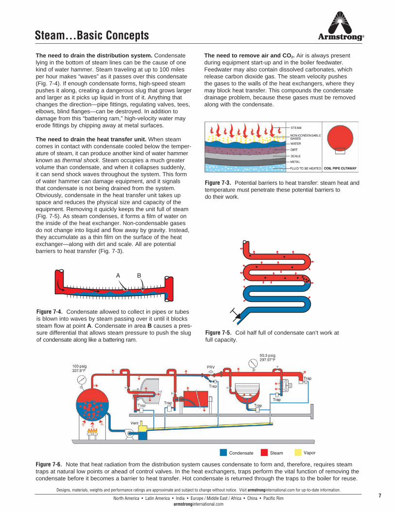
The need to drain the distribution system. Condensate lying in the bottom of steam lines can be the cause of one kind of water hammer. Steam traveling at up to 100 miles per hour makes “waves” as it passes over this condensate (Fig. 7-4). If enough condensate forms, high-speed steam pushes it along, creating a dangerous slug that grows larger and larger as it picks up liquid in front of it. Anything that changes the direction—pipe fittings, regulating valves, tees, elbows, blind flanges—can be destroyed. In addition to damage from this “battering ram,” high-velocity water may erode fittings by chipping away at metal surfaces.
The need to drain the heat transfer unit. When steam comes in contact with condensate cooled below the temper-ature of steam, it can produce another kind of water hammer known as thermal shock. Steam occupies a much greater volume than condensate, and when it collapses suddenly, it can send shock waves throughout the system. This form of water hammer can damage equipment, and it signals that condensate is not being drained from the system.Obviously, condensate in the heat transfer unit takes up space and reduces the physical size and capacity of the equipment. Removing it quickly keeps the unit full of steam (Fig. 7-5). As steam condenses, it forms a film of water on the inside of the heat exchanger. Non-condensable gases do not change into liquid and flow away by gravity. Instead, they accumulate as a thin film on the surface of the heat exchanger—along with dirt and scale. All are potential barriers to heat transfer (Fig. 7-3).
The need to remove air and CO2. Air is always present during equipment start-up and in the boiler feedwater. Feedwater may also contain dissolved carbonates, which release carbon dioxide gas. The steam velocity pushes the gases to the walls of the heat exchangers, where they may block heat transfer. This compounds the condensate drainage problem, because these gases must be removed along with the condensate.
Figure 7-3. Potential barriers to heat transfer: steam heat and temperature must penetrate these potential barriers to do their work.
Figure 7-6. Note that heat radiation from the distribution system causes condensate to form and, therefore, requires steam traps at natural low points or ahead of control valves. In the heat exchangers, traps perform the vital function of removing the condensate before it becomes a barrier to heat transfer. Hot condensate is returned through the traps to the boiler for reuse.
Figure 7-5. Coil half full of condensate can’t work at full capacity.
Figure 7-4. Condensate allowed to collect in pipes or tubes is blown into waves by steam passing over it until it blocks steam flow at point A. Condensate in area B causes a pres-sure differential that allows steam pressure to push the slug of condensate along like a battering ram.

North America • Latin America • India • Europe / Middle East / Africa • China • Pacific Rimarmstronginternational.com
Designs, materials, weights and performance ratings are approximate and subject to change without notice. Visit armstronginternational.com for up-to-date information.8
450
425
400
375
350
325
300
275
250
225
200
150
100
300 250 200 150 100 75 50 25 0 100 90 80
70 60 5
0 40 3
0 20 1
0 0
100 90 80 7
0 60 5
0 40
30 20 1
0 0
PERCENT AIR BY VOLUME–% PRESSURE–PSIG300 250 200 150 100 75 50 25 0
0
450
425400
375
350
325
300
275250
225
200
150
100
0
TE
MP
ER
AT
UR
E F
Steam…Basic Concepts
Effect of Air on Steam TemperatureWhen air and other gases enter the steam system, they consume part of the volume that steam would otherwise occupy. The temperature of the air/steam mixture falls below that of pure steam. Figure 8-7 explains the effect of air in steam lines. Table 8-2 and Chart 8-5 show the various temperature reductions caused by air at various percentages and pressures.
Effect of Air on Heat TransferThe normal flow of steam toward the heat exchanger surface carries air and other gases with it. Since they do not condense and drain by gravity, these non-condensable gases set up a barrier between the steam and the heat exchanger surface. The excellent insulating properties of air reduce heat transfer. In fact, under certain conditions as little as 1/2 of 1% by volume of air in steam can reduce heat transfer efficiency by 50% (Fig. 9-8).
When non-condensable gases (primarily air) continue to accumulate and are not removed, they may gradually fill the heat exchanger with gases and stop the flow of steam altogether. The unit is then “air bound.”
CorrosionTwo primary causes of scale and corrosion are carbon dioxide (CO2) and oxygen. CO2 enters the system as carbonates dissolved in feedwater and, when mixed with cooled condensate, creates carbonic acid. Extremely corrosive, carbonic acid can eat through piping and heat exchangers (Fig. 9-9). Oxygen enters the system as gas dissolved in the cold feedwater. It aggravates the action of carbonic acid, speeding corrosion and pitting iron and steel surfaces (Fig. 9-10).
Eliminating the UndesirablesTo summarize, traps must drain condensate because it can reduce heat transfer and cause water hammer. Traps should evacuate air and other non-condensable gases because they can reduce heat transfer by reducing steam temperature and insulating the system. They can also foster destructive corrosion. It’s essential to remove condensate, air and CO2 as quickly and completely as possible. A steam trap, which is simply an automatic valve that opens for condensate, air and CO2 and closes for steam, does this job. For economic reasons, the steam trap should do its work for long periods with minimum attention.
Chart 8-5. Air Steam MixtureTemperature reduction caused by various percentages of air at differing pressures. This chart determines the percentage of air with known pressure and temperature by determining the point of intersection between pressure, temperature and percentage of air by volume. As an example, assume system pressure of 250 psig with a temperature at the heat exchanger of 375°F. From the chart, it is determined that there is 30% air by volume in the steam.
Figure 8-7. Chamber containing air and steam delivers only the heat of the par-tial pressure of the steam, not the total pressure.
Steam chamber 100% steamTotal pressure 100 psia
Steam pressure 100 psiaSteam temperature 327.8°F
Steam chamber 90% steam and 10% airTotal pressure 100 psiaSteam pressure 90 psia
Steam temperature 320.3°F
Pressure (psig)
Temp. of Steam, No Air Present (°F)
10% 20% 30%10.3 240.1 234.3 228.0 220.925.3 267.3 261.0 254.1 246.450.3 298.0 291.0 283.5 275.175.3 320.3 312.9 304.8 295.9
100.3 338.1 330.3 321.8 312.4
Temp. of Steam Mixed With Various Percentages of Air (by Volume) (°F)
Table 8-2. Temperature Reduction Caused by Air
North America • Latin America • India • Europe / Middle East / Africa • China • Pacific Rimarmstronginternational.com
Designs, materials, weights and performance ratings are approximate and subject to change without notice. Visit armstronginternational.com for up-to-date information.9
Table 9-3. Cost of Various Sized Steam Leaks at 100 psi (Assuming steam costs $10.00/1,000 lbs)
Size of Orifice Lbs Steam Wasted
Per Month Total Cost Per Month
(USD)Total Cost Per Year
(USD
1/2" 12, 7 mm 553,000 $5,530.00 $66,360.007/16" 11, 2 mm 423,500 4,235.00 50,820.003/8" 9, 5 mm 311,000 3,110.00 37,320.005/16" 7, 9 mm 216,000 2,160.00 25,920.001/4" 6, 4 mm 138,000 1,380.00 16,560.003/16" 4, 8 mm 78,000 780.00 9,360.001/8" 3, 2 mm 34,500 345.00 4,140.00
The steam loss values assume typical condensate load for drip trap applications.Armstrong methodology for steam trap management and condensate return is sanctioned by the Clean DevelopmentMechanism of the United Nations Framework Convention on Climate Change.
Steam…Basic Concepts
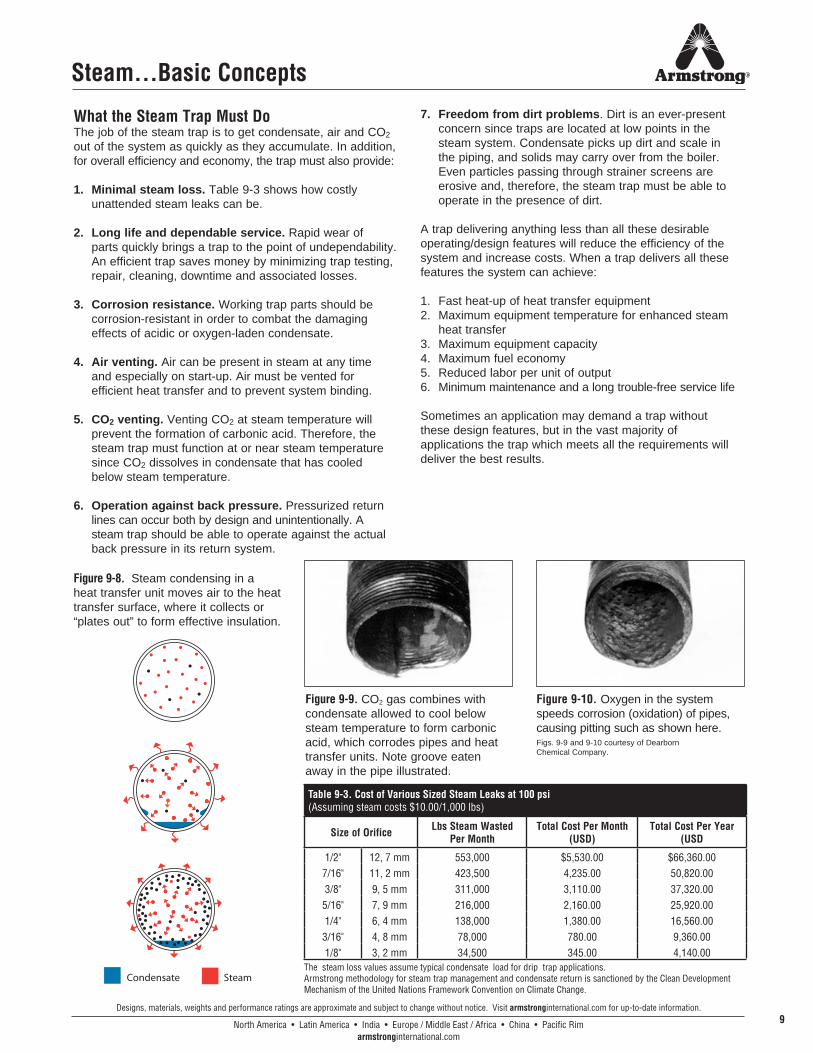
What the Steam Trap Must DoThe job of the steam trap is to get condensate, air and CO2 out of the system as quickly as they accumulate. In addition, for overall efficiency and economy, the trap must also provide:
1. Minimal steam loss. Table 9-3 shows how costly unattended steam leaks can be.
2. Long life and dependable service. Rapid wear of parts quickly brings a trap to the point of undependability. An efficient trap saves money by minimizing trap testing, repair, cleaning, downtime and associated losses.
3. Corrosion resistance. Working trap parts should be corrosion-resistant in order to combat the damaging effects of acidic or oxygen-laden condensate.
4. Air venting. Air can be present in steam at any time and especially on start-up. Air must be vented for efficient heat transfer and to prevent system binding.
5. CO2 venting. Venting CO2 at steam temperature will prevent the formation of carbonic acid. Therefore, the steam trap must function at or near steam temperature since CO2 dissolves in condensate that has cooled below steam temperature.
6. Operation against back pressure. Pressurized return lines can occur both by design and unintentionally. A steam trap should be able to operate against the actual back pressure in its return system.
7. Freedom from dirt problems. Dirt is an ever-present concern since traps are located at low points in the steam system. Condensate picks up dirt and scale in the piping, and solids may carry over from the boiler. Even particles passing through strainer screens are erosive and, therefore, the steam trap must be able to operate in the presence of dirt.
A trap delivering anything less than all these desirable operating/design features will reduce the efficiency of the system and increase costs. When a trap delivers all these features the system can achieve:
1. Fast heat-up of heat transfer equipment2. Maximum equipment temperature for enhanced steam heat transfer3. Maximum equipment capacity4. Maximum fuel economy5. Reduced labor per unit of output6. Minimum maintenance and a long trouble-free service life
Sometimes an application may demand a trap without these design features, but in the vast majority of applications the trap which meets all the requirements will deliver the best results.
Figure 9-9. CO2 gas combines with condensate allowed to cool below steam temperature to form carbonic acid, which corrodes pipes and heat transfer units. Note groove eaten away in the pipe illustrated.
Figure 9-8. Steam condensing in a heat transfer unit moves air to the heat transfer surface, where it collects or “plates out” to form effective insulation.
Figure 9-10. Oxygen in the system speeds corrosion (oxidation) of pipes, causing pitting such as shown here. Figs. 9-9 and 9-10 courtesy of Dearborn Chemical Company.
SteamCondensate
North America • Latin America • India • Europe / Middle East / Africa • China • Pacific Rimarmstronginternational.com
Designs, materials, weights and performance ratings are approximate and subject to change without notice. Visit armstronginternational.com for up-to-date information.10
Equipment Being Trapped
1st Choice, Feature Code and Alternate
Choice(s)
0 - 30 psig
Above 30 psig
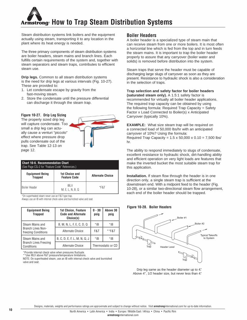
Steam Mains and Branch Lines Non-freezing Conditions
B, M, N, L, F, E, C, D, Q *IB *IB
Alternate Choice F&T **F&T
Steam Mains and Branch Lines Freezing Conditions
B, C, D, E, F, L, M, N, Q, J *IB *IB
Alternate Choice Thermostatic or CD
*Provide internal check valve when pressures fluctuate.**Use IBLV above F&T pressure/temperature limitations.NOTE: On superheated steam, use an IB with internal check valve and burnished valve and seat.
How to Trap Steam Distribution Systems
Steam distribution systems link boilers and the equipment actually using steam, transporting it to any location in the plant where its heat energy is needed.
The three primary components of steam distribution systems are boiler headers, steam mains and branch lines. Each fulfills certain requirements of the system and, together with steam separators and steam traps, contributes to efficient steam use.
Drip legs. Common to all steam distribution systems is the need for drip legs at various intervals (Fig. 10-27). These are provided to:1. Let condensate escape by gravity from the
fast-moving steam. 2. Store the condensate until the pressure differential
can discharge it through the steam trap.
Boiler HeadersA boiler header is a specialized type of steam main that can receive steam from one or more boilers. It is most often a horizontal line which is fed from the top and in turn feeds the steam mains. It is important to trap the boiler header properly to assure that any carryover (boiler water and solids) is removed before distribution into the system.
Steam traps that serve the header must be capable of discharging large slugs of carryover as soon as they are present. Resistance to hydraulic shock is also a consideration in the selection of traps.
Trap selection and safety factor for boiler headers (saturated steam only). A 1.5:1 safety factor is recommended for virtually all boiler header applications. The required trap capacity can be obtained by using the following formula: Required Trap Capacity = Safety Factor x Load Connected to Boiler(s) x Anticipated Carryover (typically 10%).
EXAMPLE: What size steam trap will be required on a connected load of 50,000 lbs/hr with an anticipated carryover of 10%? Using the formula: Required Trap Capacity = 1.5 x 50,000 x 0.10 = 7,500 lbs/hr.
The ability to respond immediately to slugs of condensate, excellent resistance to hydraulic shock, dirt-handling ability and efficient operation on very light loads are features that make the inverted bucket the most suitable steam trap for this application.
Installation. If steam flow through the header is in one direction only, a single steam trap is sufficient at the downstream end. With a midpoint feed to the header (Fig. 10-28), or a similar two-directional steam flow arrangement, each end of the boiler header should be trapped.
Figure 10-28. Boiler Headers
Drip leg same as the header diameter up to 4..’’ Above 4’’, 1/2 header size, but never less than 4.’’
Figure 10-27. Drip Leg SizingThe properly sized drip leg will capture condensate. Too small a drip leg can actu-ally cause a venturi “piccolo” effect where pressure drop pulls condensate out of the trap. See Table 12-13 on page 12.
Equipment Being Trapped
1st Choice and Feature Code Alternate Choice
Boiler Header IBLV *F&T
*On superheated steam never use an F&T type trap.Always use an IB with internal check valve and burnished valve and seat.
Chart 10-6. Recommendation Chart(See Page CG-2 for “Feature Code” References.)
M, E, L, N, B, Q
North America • Latin America • India • Europe / Middle East / Africa • China • Pacific Rimarmstronginternational.com
Designs, materials, weights and performance ratings are approximate and subject to change without notice. Visit armstronginternational.com for up-to-date information.11
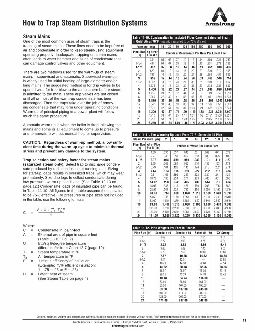
Steam MainsOne of the most common uses of steam traps is the trapping of steam mains. These lines need to be kept free of air and condensate in order to keep steam-using equipment operating properly. Inadequate trapping on steam mains often leads to water hammer and slugs of condensate that can damage control valves and other equipment.
There are two methods used for the warm-up of steam mains—supervised and automatic. Supervised warm-up is widely used for initial heating of large-diameter and/or long mains. The suggested method is for drip valves to be opened wide for free blow to the atmosphere before steam is admitted to the main. These drip valves are not closed until all or most of the warm-up condensate has been discharged. Then the traps take over the job of remov-ing condensate that may form under operating conditions. Warm-up of principal piping in a power plant will follow much the same procedure.
Automatic warm-up is when the boiler is fired, allowing the mains and some or all equipment to come up to pressure and temperature without manual help or supervision.
CAUTION: Regardless of warm-up method, allow suffi-cient time during the warm-up cycle to minimize thermal stress and prevent any damage to the system.
Trap selection and safety factor for steam mains (saturated steam only). Select trap to discharge conden-sate produced by radiation losses at running load. Sizing for start-up loads results in oversized traps, which may wear prematurely. Size drip legs to collect condensate during low-pressure, warm-up conditions. (See Table 12-13 on page 12.) Condensate loads of insulated pipe can be found in Table 11-10. All figures in the table assume the insulation to be 75% effective. For pressures or pipe sizes not included in the table, use the following formula:
C =
Where:C = Condensate in lbs/hr-footA = External area of pipe in square feet (Table 11-10, Col. 2)U = Btu/sq ft/degree temperature difference/hr from Chart 12-7 (page 12)T1 = Steam temperature in °FT2 = Air temperature in °FE = 1 minus efficiency of insulation
(Example: 75% efficient insulation: 1 - .75 = .25 or E = .25)H = Latent heat of steam (See Steam Table on page 4)
How to Trap Steam Distribution Systems
A x U x (T1- T2)EH
Table 11-11. The Warming-Up Load From 70°F, Schedule 40 Pipe2 15 30 60 125 180 250
Pipe Size (in)
wt of Pipe Per ft (lbs)
1 1.69 .030 .037 .043 .051 .063 .071 .0791-1/4 2.27 .040 .050 .057 .068 .085 .095 .1061-1/2 2.72 .048 .059 .069 .082 .101 .114 .127
2 3.65 .065 .080 .092 .110 .136 .153 .1712-1/2 5.79 .104 .126 .146 .174 .215 .262 .271
3 7.57 .133 .165 .190 .227 .282 .316 .3543-1/2 9.11 .162 .198 .229 .273 .339 .381 .426
4 10.79 .190 .234 .271 .323 .400 .451 .5055 14.62 .258 .352 .406 .439 .544 .612 .6846 18.97 .335 .413 .476 .569 .705 .795 .8828 28.55 .504 .620 .720 .860 1.060 1.190 1.340
10 40.48 .714 .880 1.020 1.210 1.500 1.690 1.89012 53.60 .945 1.170 1.350 1.610 2.000 2.240 2.51014 63.00 1.110 1.370 1.580 1.890 2.340 2.640 2.94016 83.00 1.460 1.810 2.080 2.490 3.080 3.470 3.88018 105.00 1.850 2.280 2.630 3.150 3.900 4.400 4.90020 123.00 2.170 2.680 3.080 3.690 4.570 5.150 5.75024 171.00 3.020 3.720 4.290 5.130 6.350 7.150 8.000
Steam Pressure, psig
Pounds of Water Per Lineal Foot
Table 11-10. Condensation in Insulated Pipes Carrying Saturated Steamin Quiet Air at 70°F (Insulation assumed to be 75% efficient.)
15 30 60 125 180 250 450 600 900
Pipe Size (in)
sq ft Per Lineal ft
1 .344 .05 .06 .07 .10 .12 .14 .186 .221 .2891-1/4 .434 .06 .07 .09 .12 .14 .17 .231 .273 .3591-1/2 .497 .07 .08 .10 .14 .16 .19 .261 .310 .406
2 .622 .08 .10 .13 .17 .20 .23 .320 .379 .4982-1/2 .753 .10 .12 .15 .20 .24 .28 .384 .454 .596
3 .916 .12 .14 .18 .24 .28 .33 .460 .546 .7143-1/2 1.047 .13 .16 .20 .27 .32 .38 .520 .617 .807
4 1.178 .15 .18 .22 .30 .36 .43 .578 .686 .8975 1.456 .18 .22 .27 .37 .44 .51 .698 .826 1.0786 1.735 .20 .25 .32 .44 .51 .59 .809 .959 1.2538 2.260 .27 .32 .41 .55 .66 .76 1.051 1.244 1.628
10 2.810 .32 .39 .51 .68 .80 .94 1.301 1.542 2.01912 3.340 .38 .46 .58 .80 .92 1.11 1.539 1.821 2.39314 3.670 .42 .51 .65 .87 1.03 1.21 1.688 1.999 2.62416 4.200 .47 .57 .74 .99 1.19 1.38 1.927 2.281 2.99718 4.710 .53 .64 .85 1.11 1.31 1.53 2.151 2.550 3.35120 5.250 .58 .71 .91 1.23 1.45 1.70 2.387 2.830 3.72524 6.280 .68 .84 1.09 1.45 1.71 2.03 2.833 3.364 4.434
Pounds of Condensate Per Hour Per Lineal Foot
Pressure, psig
Table 11-12. Pipe Weights Per Foot in PoundsPipe Size (in) Schedule 40 Schedule 80 Schedule 160 XX Strong
1 1.69 2.17 2.85 3.661-1/4 2.27 3.00 3.76 5.211-1/2 2.72 3.63 4.86 6.41
2 3.65 5.02 7.45 9.032-1/2 5.79 7.66 10.01 13.69
3 7.57 10.25 14.32 18.583-1/2 9.11 12.51 — 22.85
4 10.79 14.98 22.60 27.545 14.62 20.78 32.96 38.556 18.97 28.57 45.30 53.168 28.55 43.39 74.70 72.42
10 40.48 54.74 116.00 —12 53.60 88.60 161.00 —14 63.00 107.00 190.00 —16 83.00 137.00 245.00 —18 105.00 171.00 309.00 —20 123.00 209.00 379.00 —24 171.00 297.00 542.00 —
North America • Latin America • India • Europe / Middle East / Africa • China • Pacific Rimarmstronginternational.com
Designs, materials, weights and performance ratings are approximate and subject to change without notice. Visit armstronginternational.com for up-to-date information.12
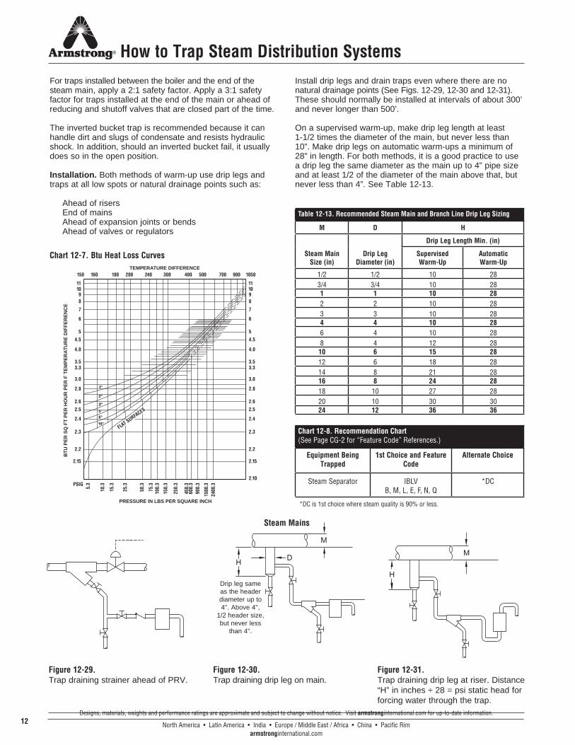
Table 12-13. Recommended Steam Main and Branch Line Drip Leg Sizing
M D H
Steam Main Size (in)
Drip Leg Diameter (in)
Drip Leg Length Min. (in)
Supervised Warm-Up
Automatic Warm-Up
1/2 1/2 10 283/4 3/4 10 281 1 10 282 2 10 283 3 10 284 4 10 286 4 10 288 4 12 2810 6 15 2812 6 18 2814 8 21 2816 8 24 2818 10 27 2820 10 30 3024 12 36 36
Chart 12-8. Recommendation Chart (See Page CG-2 for “Feature Code” References.)
Equipment Being Trapped
1st Choice and Feature Code
Alternate Choice
Steam Separator IBLV B, M, L, E, F, N, Q
*DC
*DC is 1st choice where steam quality is 90% or less.
111098
7
6
5
4.5
4.0
3.53.3
3.0
2.8
2.6
2.5
2.4
2.3
2.2
2.15
PSIG
111098
7
6
5
4.5
4.0
3.53.3
3.0
2.8
2.6
2.5
2.4
2.3
2.2
2.15
2.10
5.3
10.3
15.3
25.3
50.3
75.3
100.
3
150.
3
250.
3
450.
360
0.3
900.
3
1500
.324
00.3
PRESSURE IN LBS PER SQUARE INCH
BT
U P
ER
SQ
FT
PE
R H
OU
R P
ER
F T
EM
PE
RA
TU
RE
DIF
FE
RE
NC
E
TEMPERATURE DIFFERENCE150 160 180 200 240 300 400 500 700 900 1050
1"
2"
3"
5"
2"
5"
6"
10"FLAT SURFACES
How to Trap Steam Distribution Systems
For traps installed between the boiler and the end of the steam main, apply a 2:1 safety factor. Apply a 3:1 safety factor for traps installed at the end of the main or ahead of reducing and shutoff valves that are closed part of the time.
The inverted bucket trap is recommended because it can handle dirt and slugs of condensate and resists hydraulic shock. In addition, should an inverted bucket fail, it usually does so in the open position.
Installation. Both methods of warm-up use drip legs and traps at all low spots or natural drainage points such as:
Ahead of risers End of mains Ahead of expansion joints or bends Ahead of valves or regulators
Install drip legs and drain traps even where there are no natural drainage points (See Figs. 12-29, 12-30 and 12-31). These should normally be installed at intervals of about 300’ and never longer than 500’.
On a supervised warm-up, make drip leg length at least 1-1/2 times the diameter of the main, but never less than 10”. Make drip legs on automatic warm-ups a minimum of 28” in length. For both methods, it is a good practice to use a drip leg the same diameter as the main up to 4” pipe size and at least 1/2 of the diameter of the main above that, but never less than 4”. See Table 12-13.
Chart 12-7. Btu Heat Loss Curves
Figure 12-29. Trap draining strainer ahead of PRV.
Figure 12-30. Trap draining drip leg on main.
Figure 12-31. Trap draining drip leg at riser. Distance “H” in inches ÷ 28 = psi static head for forcing water through the trap.
Drip leg same as the header diameter up to 4''. Above 4'',
1/2 header size, but never less
than 4''.
Steam Mains
North America • Latin America • India • Europe / Middle East / Africa • China • Pacific Rimarmstronginternational.com
Designs, materials, weights and performance ratings are approximate and subject to change without notice. Visit armstronginternational.com for up-to-date information.13
How to Trap Steam Distribution Systems
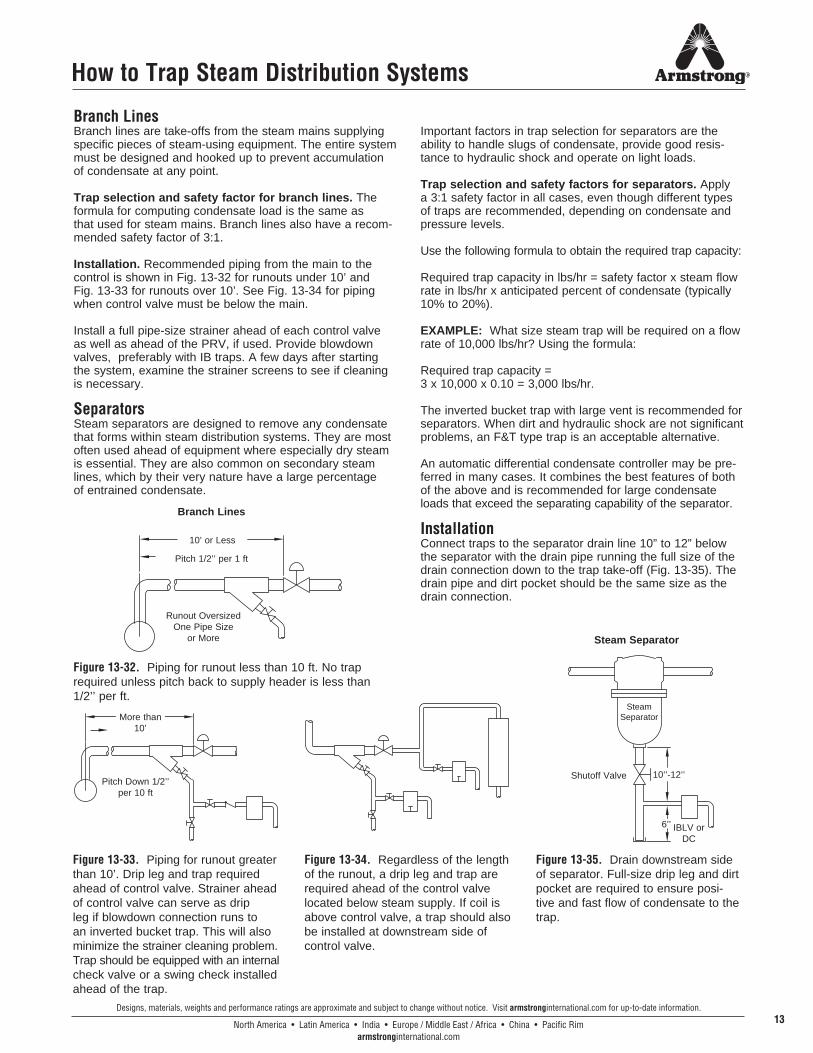
Branch LinesBranch lines are take-offs from the steam mains supplying specific pieces of steam-using equipment. The entire system must be designed and hooked up to prevent accumulation of condensate at any point.
Trap selection and safety factor for branch lines. The formula for computing condensate load is the same as that used for steam mains. Branch lines also have a recom-mended safety factor of 3:1.
Installation. Recommended piping from the main to the control is shown in Fig. 13-32 for runouts under 10’ and Fig. 13-33 for runouts over 10’. See Fig. 13-34 for piping when control valve must be below the main.
Install a full pipe-size strainer ahead of each control valve as well as ahead of the PRV, if used. Provide blowdown valves, preferably with IB traps. A few days after starting the system, examine the strainer screens to see if cleaning is necessary.
SeparatorsSteam separators are designed to remove any condensate that forms within steam distribution systems. They are most often used ahead of equipment where especially dry steam is essential. They are also common on secondary steam lines, which by their very nature have a large percentage of entrained condensate.
Important factors in trap selection for separators are the ability to handle slugs of condensate, provide good resis-tance to hydraulic shock and operate on light loads.
Trap selection and safety factors for separators. Apply a 3:1 safety factor in all cases, even though different types of traps are recommended, depending on condensate and pressure levels.
Use the following formula to obtain the required trap capacity:
Required trap capacity in lbs/hr = safety factor x steam flow rate in lbs/hr x anticipated percent of condensate (typically 10% to 20%).
EXAMPLE: What size steam trap will be required on a flow rate of 10,000 lbs/hr? Using the formula:
Required trap capacity = 3 x 10,000 x 0.10 = 3,000 lbs/hr.
The inverted bucket trap with large vent is recommended for separators. When dirt and hydraulic shock are not significant problems, an F&T type trap is an acceptable alternative.
An automatic differential condensate controller may be pre-ferred in many cases. It combines the best features of both of the above and is recommended for large condensate loads that exceed the separating capability of the separator.
InstallationConnect traps to the separator drain line 10” to 12” below the separator with the drain pipe running the full size of the drain connection down to the trap take-off (Fig. 13-35). The drain pipe and dirt pocket should be the same size as the drain connection.
Figure 13-33. Piping for runout greater than 10’. Drip leg and trap required ahead of control valve. Strainer ahead of control valve can serve as drip leg if blowdown connection runs to an inverted bucket trap. This will also minimize the strainer cleaning problem. Trap should be equipped with an internal check valve or a swing check installed ahead of the trap.
Figure 13-34. Regardless of the length of the runout, a drip leg and trap are required ahead of the control valve located below steam supply. If coil is above control valve, a trap should also be installed at downstream side of control valve.
Figure 13-35. Drain downstream side of separator. Full-size drip leg and dirt pocket are required to ensure posi-tive and fast flow of condensate to the trap.
Figure 13-32. Piping for runout less than 10 ft. No trap required unless pitch back to supply header is less than 1/2’’ per ft.
10’ or Less
Pitch 1/2’’ per 1 ft
Runout Oversized One Pipe Size
or More
More than 10’
Pitch Down 1/2’’ per 10 ft
Steam Separator
Shutoff Valve 10’’-12’’
IBLV or DC
Steam Separator
Branch Lines
6’’

Armstrong provides intelligent system solutions that improve utility performance, lower energy consumption,and reduce environmental emissions while providing an “enjoyable experience.”
Armstrong InternationalNorth America • Latin America • India • Europe / Middle East / Africa • China • Pacific Rim
857-ENPrinted in U.S.A. - 4/15
© 2015 Armstrong International, Inc.
armstronginternational.com


![steam trap performance[1]](https://img.pdfslide.net/doc/110x75/551b18ab4a795911748b45cc/steam-trap-performance1.jpg)