Embed Size (px)
Citation preview
How to Use a Breadboard a learn.sparkfun.comtutorial
Available online at: http://sfe.io/t47
Contents
IntroductionHistoryWhy Use Breadboards?Anatomy of a BreadboardProviding Power to a BreadboardBuilding Your First Breadboard CircuitPurchasing a BreadboardResources and Going Further
Introduction
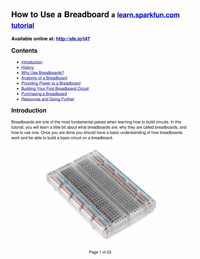
Breadboards are one of the most fundamental pieces when learning how to build circuits. In thistutorial, you will learn a little bit about what breadboards are, why they are called breadboards, andhow to use one. Once you are done you should have a basic understanding of how breadboardswork and be able to build a basic circuit on a breadboard.
Page 1 of 23
Suggested Reading
Here are some tutorials and concepts you may want to explore before learning about breadboards:
V,C,R, and Ohm’s LawWhat is a circuitWorking with wireReading SchematicsCommon ConnectorsHow to Use a Multimeter
History
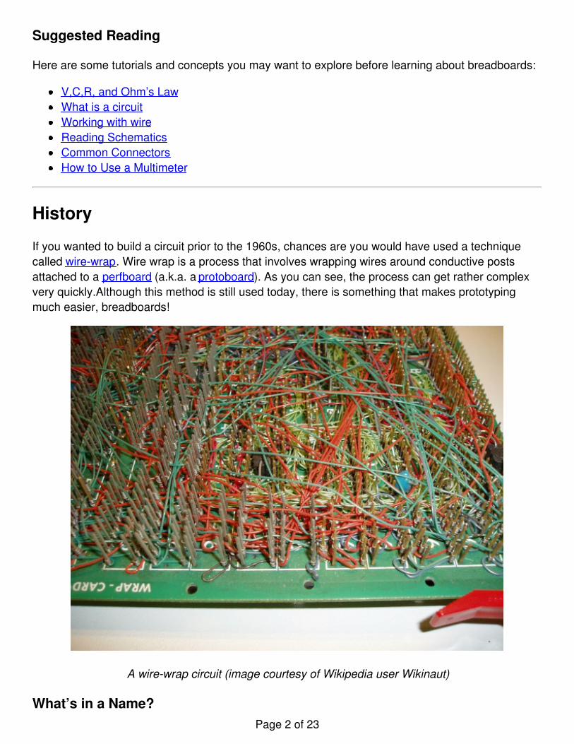
If you wanted to build a circuit prior to the 1960s, chances are you would have used a techniquecalled wire-wrap. Wire wrap is a process that involves wrapping wires around conductive postsattached to a perfboard (a.k.a. a protoboard). As you can see, the process can get rather complexvery quickly.Although this method is still used today, there is something that makes prototypingmuch easier, breadboards!
A wire-wrap circuit (image courtesy of Wikipedia user Wikinaut)
What’s in a Name?Page 2 of 23
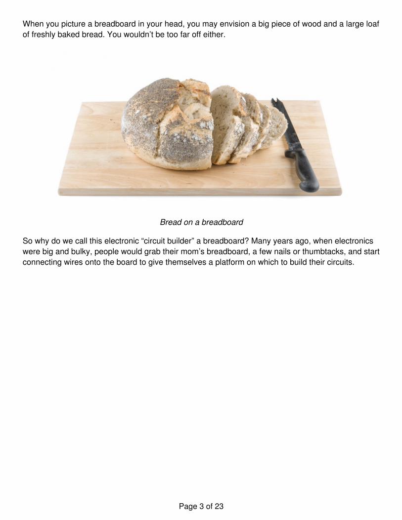
When you picture a breadboard in your head, you may envision a big piece of wood and a large loafof freshly baked bread. You wouldn’t be too far off either.
Bread on a breadboard
So why do we call this electronic “circuit builder” a breadboard? Many years ago, when electronicswere big and bulky, people would grab their mom’s breadboard, a few nails or thumbtacks, and startconnecting wires onto the board to give themselves a platform on which to build their circuits.
Page 3 of 23
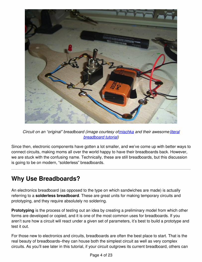
Circuit on an “original” breadboard (image courtesy of mischka and their awesome literalbreadboard tutorial)
Since then, electronic components have gotten a lot smaller, and we’ve come up with better ways toconnect circuits, making moms all over the world happy to have their breadboards back. However,we are stuck with the confusing name. Technically, these are still breadboards, but this discussionis going to be on modern, “solderless” breadboards.
Why Use Breadboards?
An electronics breadboard (as opposed to the type on which sandwiches are made) is actuallyreferring to a solderless breadboard. These are great units for making temporary circuits andprototyping, and they require absolutely no soldering.
Prototyping is the process of testing out an idea by creating a preliminary model from which otherforms are developed or copied, and it is one of the most common uses for breadboards. If youaren’t sure how a circuit will react under a given set of parameters, it’s best to build a prototype andtest it out.
For those new to electronics and circuits, breadboards are often the best place to start. That is thereal beauty of breadboards–they can house both the simplest circuit as well as very complexcircuits. As you’ll see later in this tutorial, if your circuit outgrows its current breadboard, others can
Page 4 of 23
be be attached to accommodate circuits of all sizes and complexities.
Another common use of breadboards is testing out new parts, such as Integrated circuits (ICs).When you are trying to figure out how a part works and constantly rewiring things, you don’t want tohave to solder your connections each time.
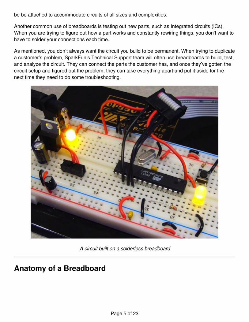
As mentioned, you don’t always want the circuit you build to be permanent. When trying to duplicatea customer’s problem, SparkFun’s Technical Support team will often use breadboards to build, test,and analyze the circuit. They can connect the parts the customer has, and once they’ve gotten thecircuit setup and figured out the problem, they can take everything apart and put it aside for thenext time they need to do some troubleshooting.
A circuit built on a solderless breadboard
Anatomy of a Breadboard
Page 5 of 23
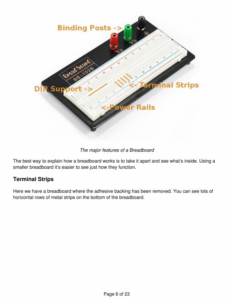
The major features of a Breadboard
The best way to explain how a breadboard works is to take it apart and see what’s inside. Using asmaller breadboard it’s easier to see just how they function.
Terminal Strips
Here we have a breadboard where the adhesive backing has been removed. You can see lots ofhorizontal rows of metal strips on the bottom of the breadboard.
Page 6 of 23
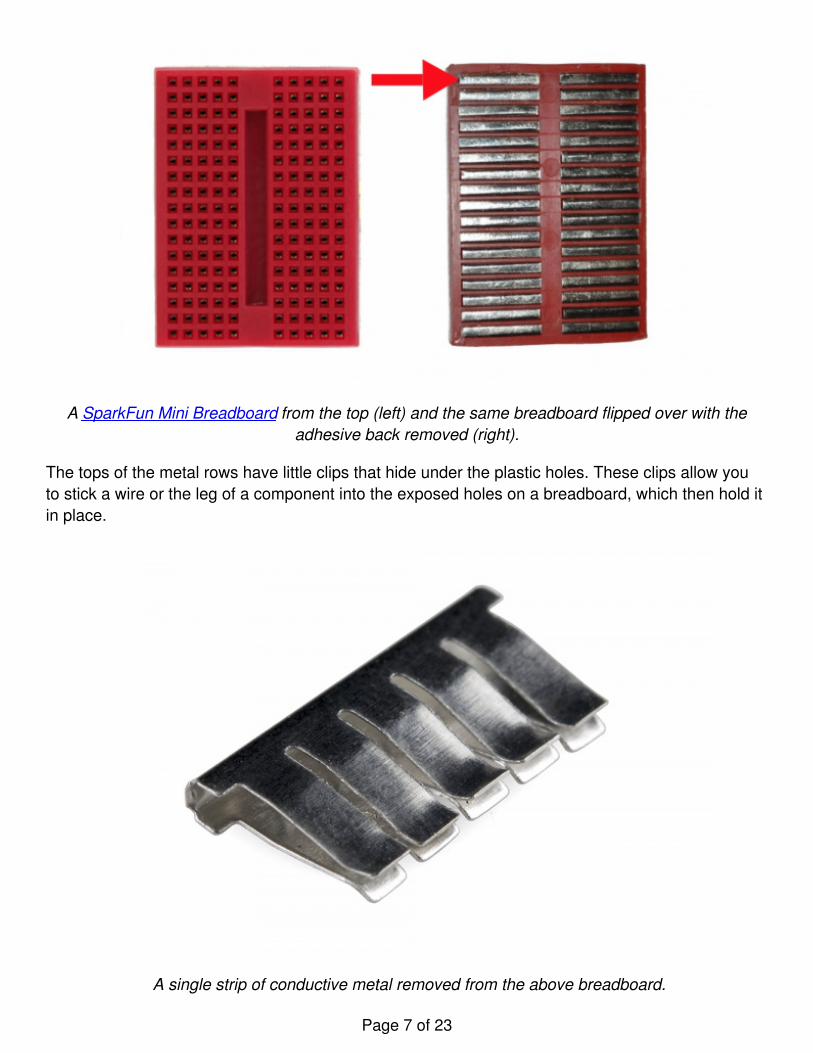
A SparkFun Mini Breadboard from the top (left) and the same breadboard flipped over with theadhesive back removed (right).
The tops of the metal rows have little clips that hide under the plastic holes. These clips allow youto stick a wire or the leg of a component into the exposed holes on a breadboard, which then hold itin place.
A single strip of conductive metal removed from the above breadboard.
Page 7 of 23
Once inserted that component will be electrically connected to anything else placed in that row.This is because the metal rows are conductive and allow current to flow from any point in that strip.
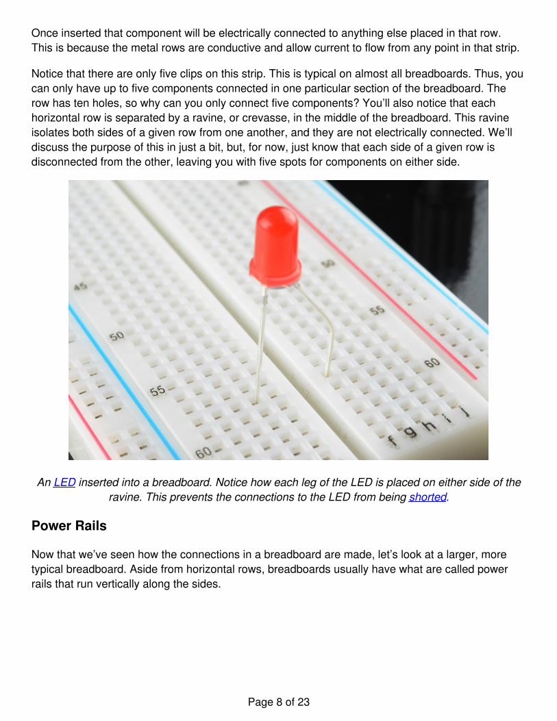
Notice that there are only five clips on this strip. This is typical on almost all breadboards. Thus, youcan only have up to five components connected in one particular section of the breadboard. Therow has ten holes, so why can you only connect five components? You’ll also notice that eachhorizontal row is separated by a ravine, or crevasse, in the middle of the breadboard. This ravineisolates both sides of a given row from one another, and they are not electrically connected. We’lldiscuss the purpose of this in just a bit, but, for now, just know that each side of a given row isdisconnected from the other, leaving you with five spots for components on either side.
An LED inserted into a breadboard. Notice how each leg of the LED is placed on either side of theravine. This prevents the connections to the LED from being shorted.
Power Rails
Now that we’ve seen how the connections in a breadboard are made, let’s look at a larger, moretypical breadboard. Aside from horizontal rows, breadboards usually have what are called powerrails that run vertically along the sides.
Page 8 of 23
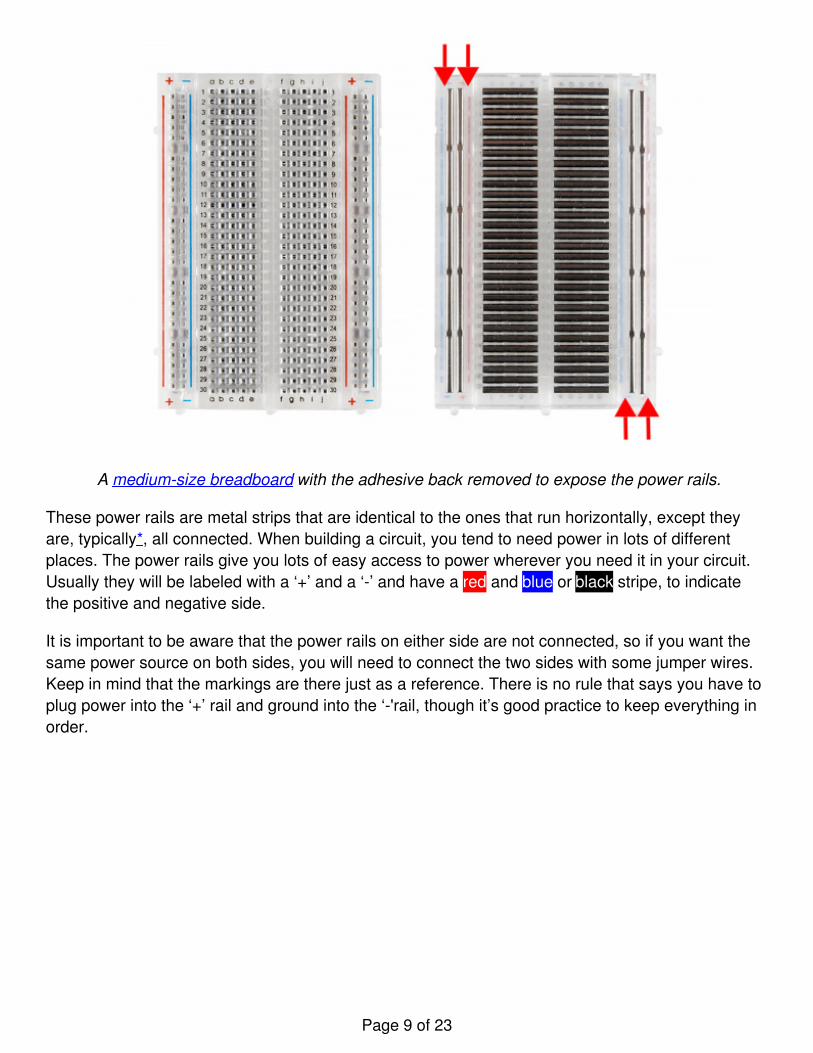
A medium-size breadboard with the adhesive back removed to expose the power rails.
These power rails are metal strips that are identical to the ones that run horizontally, except theyare, typically*, all connected. When building a circuit, you tend to need power in lots of differentplaces. The power rails give you lots of easy access to power wherever you need it in your circuit.Usually they will be labeled with a ‘+’ and a ‘-’ and have a red and blue or black stripe, to indicatethe positive and negative side.
It is important to be aware that the power rails on either side are not connected, so if you want thesame power source on both sides, you will need to connect the two sides with some jumper wires.Keep in mind that the markings are there just as a reference. There is no rule that says you have toplug power into the ‘+’ rail and ground into the ‘-'rail, though it’s good practice to keep everything inorder.
Page 9 of 23
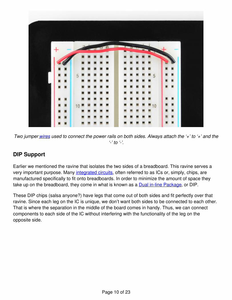
Two jumper wires used to connect the power rails on both sides. Always attach the ‘+’ to ‘+’ and the‘-’ to ‘-’.
DIP Support
Earlier we mentioned the ravine that isolates the two sides of a breadboard. This ravine serves avery important purpose. Many integrated circuits, often referred to as ICs or, simply, chips, aremanufactured specifically to fit onto breadboards. In order to minimize the amount of space theytake up on the breadboard, they come in what is known as a Dual in-line Package, or DIP.
These DIP chips (salsa anyone?) have legs that come out of both sides and fit perfectly over thatravine. Since each leg on the IC is unique, we don’t want both sides to be connected to each other.That is where the separation in the middle of the board comes in handy. Thus, we can connectcomponents to each side of the IC without interfering with the functionality of the leg on theopposite side.
Page 10 of 23
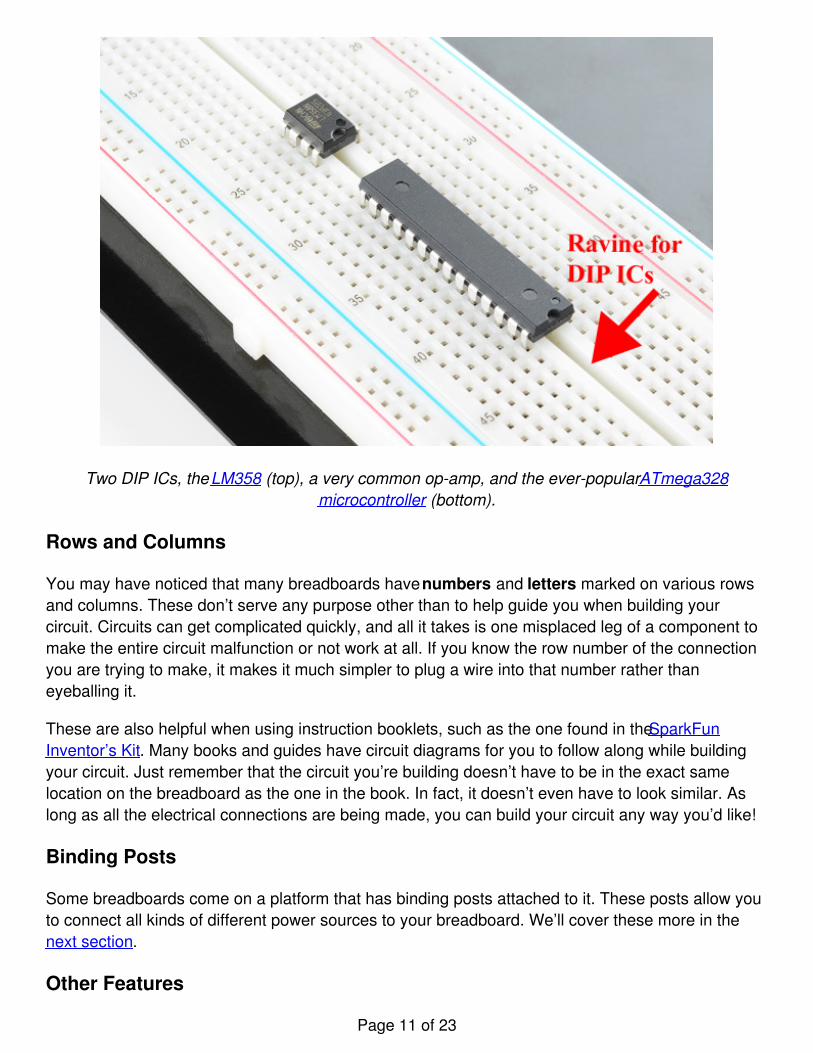
Two DIP ICs, the LM358 (top), a very common op-amp, and the ever-popular ATmega328microcontroller (bottom).
Rows and Columns
You may have noticed that many breadboards have numbers and letters marked on various rowsand columns. These don’t serve any purpose other than to help guide you when building yourcircuit. Circuits can get complicated quickly, and all it takes is one misplaced leg of a component tomake the entire circuit malfunction or not work at all. If you know the row number of the connectionyou are trying to make, it makes it much simpler to plug a wire into that number rather thaneyeballing it.
These are also helpful when using instruction booklets, such as the one found in the SparkFunInventor’s Kit. Many books and guides have circuit diagrams for you to follow along while buildingyour circuit. Just remember that the circuit you’re building doesn’t have to be in the exact samelocation on the breadboard as the one in the book. In fact, it doesn’t even have to look similar. Aslong as all the electrical connections are being made, you can build your circuit any way you’d like!
Binding Posts
Some breadboards come on a platform that has binding posts attached to it. These posts allow youto connect all kinds of different power sources to your breadboard. We’ll cover these more in thenext section.
Other Features
Page 11 of 23
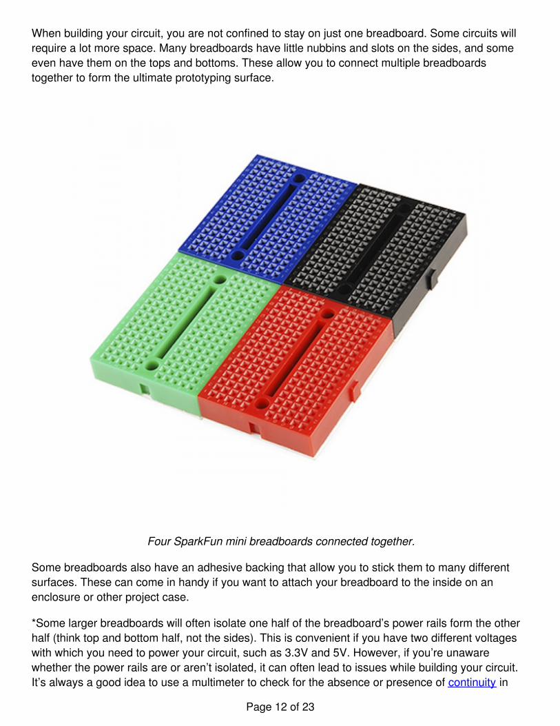
When building your circuit, you are not confined to stay on just one breadboard. Some circuits willrequire a lot more space. Many breadboards have little nubbins and slots on the sides, and someeven have them on the tops and bottoms. These allow you to connect multiple breadboardstogether to form the ultimate prototyping surface.
Four SparkFun mini breadboards connected together.
Some breadboards also have an adhesive backing that allow you to stick them to many differentsurfaces. These can come in handy if you want to attach your breadboard to the inside on anenclosure or other project case.
*Some larger breadboards will often isolate one half of the breadboard’s power rails form the otherhalf (think top and bottom half, not the sides). This is convenient if you have two different voltageswith which you need to power your circuit, such as 3.3V and 5V. However, if you’re unawarewhether the power rails are or aren’t isolated, it can often lead to issues while building your circuit.It’s always a good idea to use a multimeter to check for the absence or presence of continuity in
Page 12 of 23
your breadboard’s power rails.
Providing Power to a Breadboard
When it comes to providing power to you breadboard, there are numerous options.
Borrowing from Other Power Sources
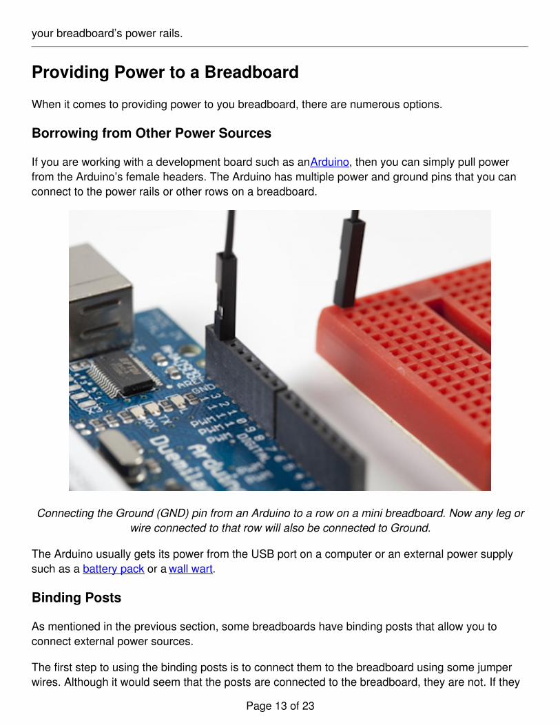
If you are working with a development board such as an Arduino, then you can simply pull powerfrom the Arduino’s female headers. The Arduino has multiple power and ground pins that you canconnect to the power rails or other rows on a breadboard.
Connecting the Ground (GND) pin from an Arduino to a row on a mini breadboard. Now any leg orwire connected to that row will also be connected to Ground.
The Arduino usually gets its power from the USB port on a computer or an external power supplysuch as a battery pack or a wall wart.
Binding Posts
As mentioned in the previous section, some breadboards have binding posts that allow you toconnect external power sources.
The first step to using the binding posts is to connect them to the breadboard using some jumperwires. Although it would seem that the posts are connected to the breadboard, they are not. If they
Page 13 of 23
were, you would be limited to where you could and couldn’t provide power. As we’ve seen,breadboards are meant to be totally customizable, so it would make sense that the binding postsare no different.
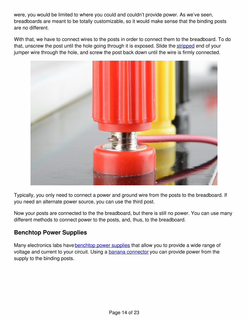
With that, we have to connect wires to the posts in order to connect them to the breadboard. To dothat, unscrew the post until the hole going through it is exposed. Slide the stripped end of yourjumper wire through the hole, and screw the post back down until the wire is firmly connected.
Typically, you only need to connect a power and ground wire from the posts to the breadboard. Ifyou need an alternate power source, you can use the third post.
Now your posts are connected to the the breadboard, but there is still no power. You can use manydifferent methods to connect power to the posts, and, thus, to the breadboard.
Benchtop Power Supplies
Many electronics labs have benchtop power supplies that allow you to provide a wide range ofvoltage and current to your circuit. Using a banana connector you can provide power from thesupply to the binding posts.
Page 14 of 23
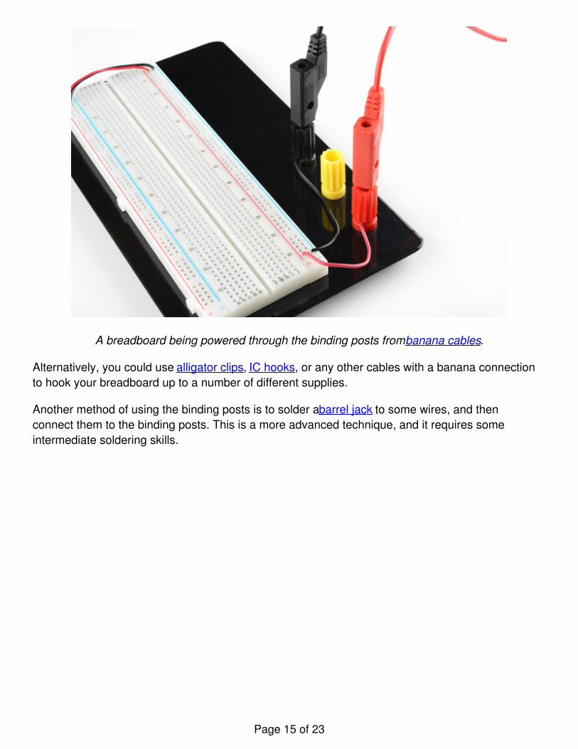
A breadboard being powered through the binding posts from banana cables.
Alternatively, you could use alligator clips, IC hooks, or any other cables with a banana connectionto hook your breadboard up to a number of different supplies.
Another method of using the binding posts is to solder a barrel jack to some wires, and thenconnect them to the binding posts. This is a more advanced technique, and it requires someintermediate soldering skills.
Page 15 of 23
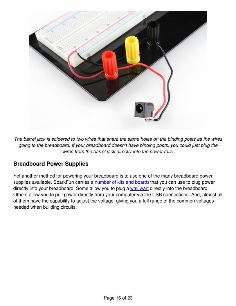
The barrel jack is soldered to two wires that share the same holes on the binding posts as the wiresgoing to the breadboard. If your breadboard doesn’t have binding posts, you could just plug the
wires from the barrel jack directly into the power rails.
Breadboard Power Supplies
Yet another method for powering your breadboard is to use one of the many breadboard powersupplies available. SparkFun carries a number of kits and boards that you can use to plug powerdirectly into your breadboard. Some allow you to plug a wall wart directly into the breadboard.Others allow you to pull power directly from your computer via the USB connections. And, almost allof them have the capability to adjust the voltage, giving you a full range of the common voltagesneeded when building circuits.
Page 16 of 23
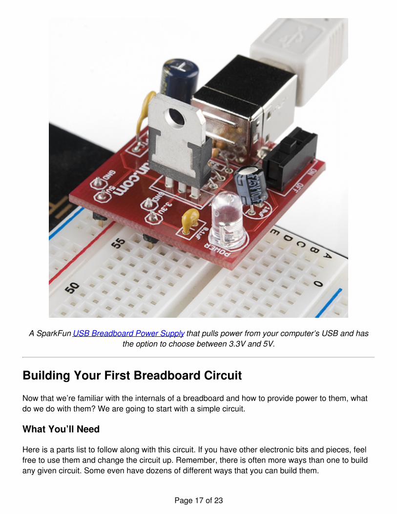
A SparkFun USB Breadboard Power Supply that pulls power from your computer’s USB and hasthe option to choose between 3.3V and 5V.
Building Your First Breadboard Circuit
Now that we’re familiar with the internals of a breadboard and how to provide power to them, whatdo we do with them? We are going to start with a simple circuit.
What You’ll Need
Here is a parts list to follow along with this circuit. If you have other electronic bits and pieces, feelfree to use them and change the circuit up. Remember, there is often more ways than one to buildany given circuit. Some even have dozens of different ways that you can build them.
Page 17 of 23
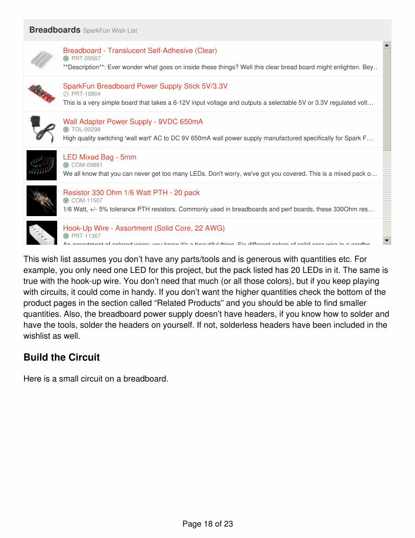
Breadboards SparkFun Wish List
Breadboard - Translucent Self-Adhesive (Clear)PRT-09567
**Description**: Ever wonder what goes on inside these things? Well this clear bread board might enlighten. Bey…
SparkFun Breadboard Power Supply Stick 5V/3.3VPRT-10804
This is a very simple board that takes a 6-12V input voltage and outputs a selectable 5V or 3.3V regulated volt…
Wall Adapter Power Supply - 9VDC 650mATOL-00298
High quality switching 'wall wart' AC to DC 9V 650mA wall power supply manufactured specifically for Spark F…
LED Mixed Bag - 5mmCOM-09881
We all know that you can never get too many LEDs. Don't worry, we've got you covered. This is a mixed pack o…
Resistor 330 Ohm 1/6 Watt PTH - 20 packCOM-11507
1/6 Watt, +/- 5% tolerance PTH resistors. Commonly used in breadboards and perf boards, these 330Ohm res…
Hook-Up Wire - Assortment (Solid Core, 22 AWG)PRT-11367
An assortment of colored wires: you know it's a beautiful thing. Six different colors of solid core wire in a cardbo…
Momentary Pushbutton Switch - 12mm SquareCOM-09190
This is a standard 12mm square momentary button. What we really like is the large button head and good tact…
Wire Strippers 30AWGTOL-08696
These are good quality 6" wire strippers with 6 gauge settings. We really wanted to stock these because they s…
Solderless Headers - 10-pin StraightPRT-10527
These are just what they sound like, solderless pin headers! Great for throwing together a quick prototype or if…
View Breadboards on SparkFun.com
This wish list assumes you don’t have any parts/tools and is generous with quantities etc. Forexample, you only need one LED for this project, but the pack listed has 20 LEDs in it. The same istrue with the hook-up wire. You don’t need that much (or all those colors), but if you keep playingwith circuits, it could come in handy. If you don’t want the higher quantities check the bottom of theproduct pages in the section called “Related Products” and you should be able to find smallerquantities. Also, the breadboard power supply doesn’t have headers, if you know how to solder andhave the tools, solder the headers on yourself. If not, solderless headers have been included in thewishlist as well.
Build the Circuit
Here is a small circuit on a breadboard.
Page 18 of 23
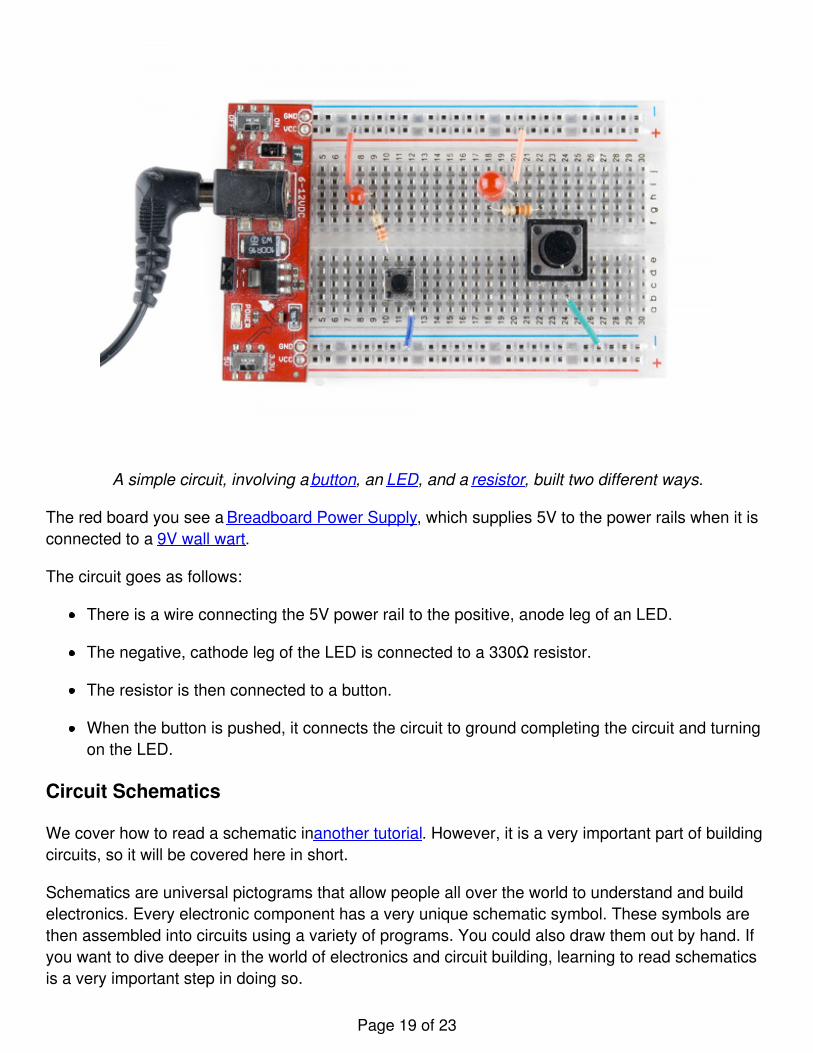
A simple circuit, involving a button, an LED, and a resistor, built two different ways.
The red board you see a Breadboard Power Supply, which supplies 5V to the power rails when it isconnected to a 9V wall wart.
The circuit goes as follows:
There is a wire connecting the 5V power rail to the positive, anode leg of an LED.
The negative, cathode leg of the LED is connected to a 330Ω resistor.
The resistor is then connected to a button.
When the button is pushed, it connects the circuit to ground completing the circuit and turningon the LED.
Circuit Schematics
We cover how to read a schematic in another tutorial. However, it is a very important part of buildingcircuits, so it will be covered here in short.
Schematics are universal pictograms that allow people all over the world to understand and buildelectronics. Every electronic component has a very unique schematic symbol. These symbols arethen assembled into circuits using a variety of programs. You could also draw them out by hand. Ifyou want to dive deeper in the world of electronics and circuit building, learning to read schematicsis a very important step in doing so.
Page 19 of 23
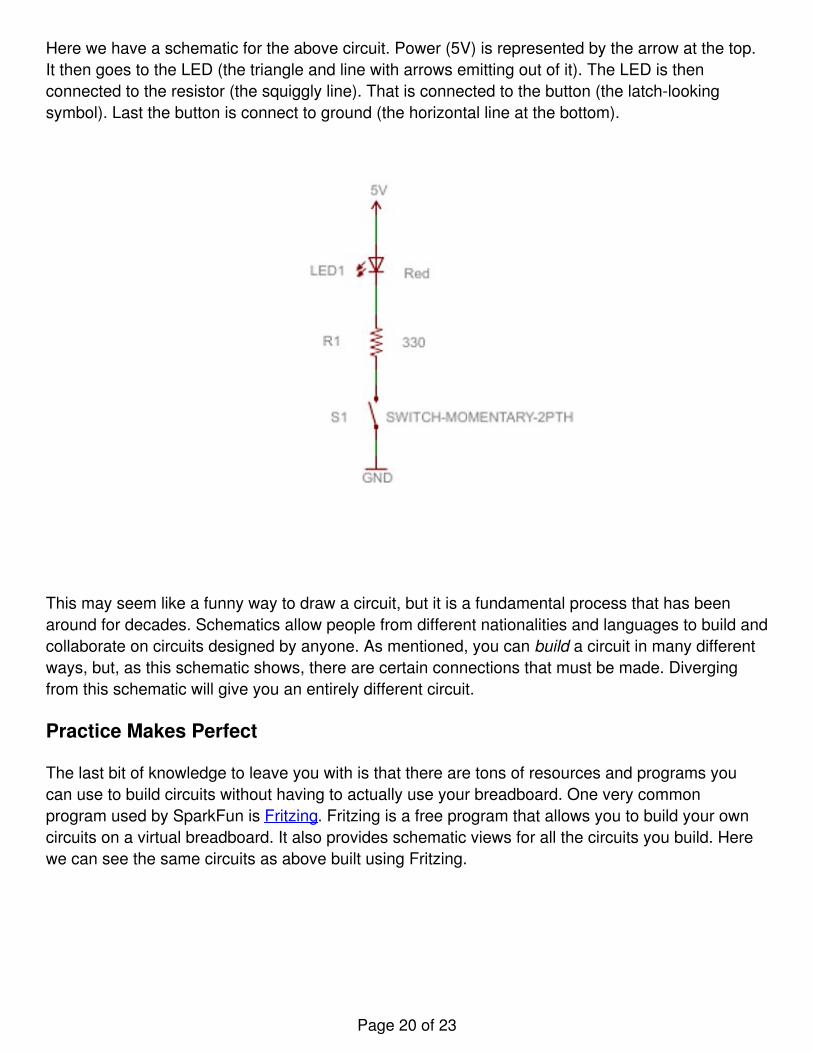
Here we have a schematic for the above circuit. Power (5V) is represented by the arrow at the top.It then goes to the LED (the triangle and line with arrows emitting out of it). The LED is thenconnected to the resistor (the squiggly line). That is connected to the button (the latch-lookingsymbol). Last the button is connect to ground (the horizontal line at the bottom).
This may seem like a funny way to draw a circuit, but it is a fundamental process that has beenaround for decades. Schematics allow people from different nationalities and languages to build andcollaborate on circuits designed by anyone. As mentioned, you can build a circuit in many differentways, but, as this schematic shows, there are certain connections that must be made. Divergingfrom this schematic will give you an entirely different circuit.
Practice Makes Perfect
The last bit of knowledge to leave you with is that there are tons of resources and programs youcan use to build circuits without having to actually use your breadboard. One very commonprogram used by SparkFun is Fritzing. Fritzing is a free program that allows you to build your owncircuits on a virtual breadboard. It also provides schematic views for all the circuits you build. Herewe can see the same circuits as above built using Fritzing.
Page 20 of 23
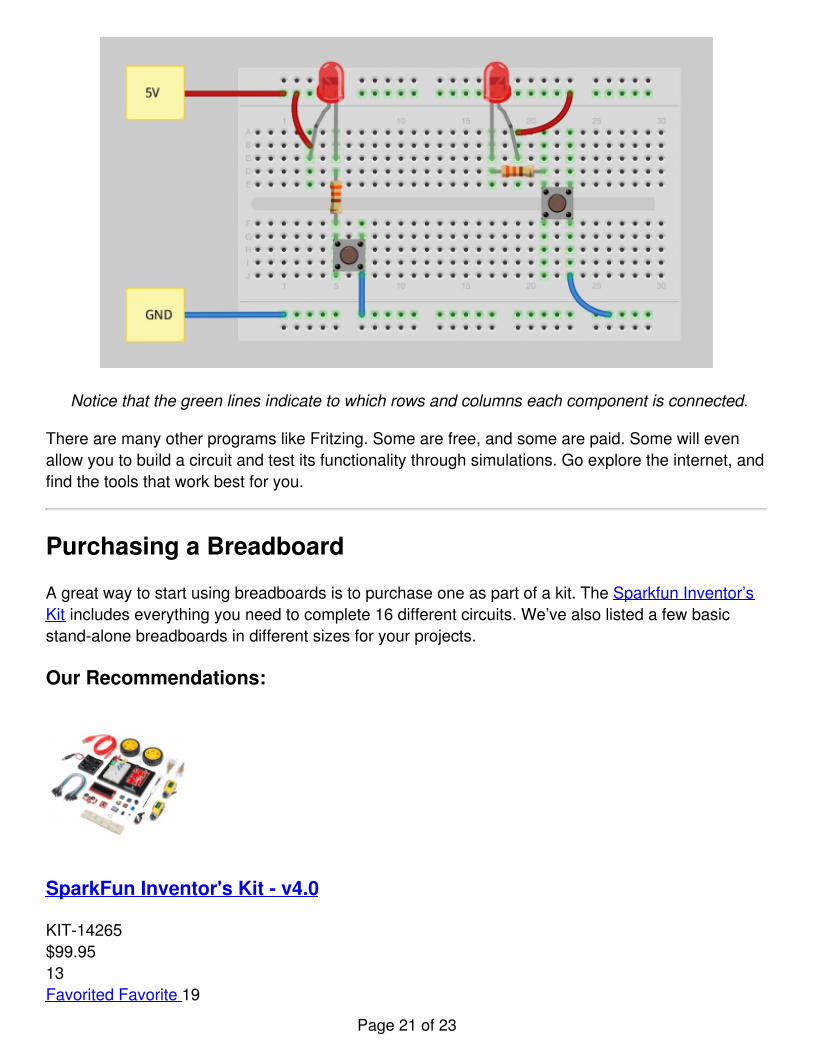
Notice that the green lines indicate to which rows and columns each component is connected.
There are many other programs like Fritzing. Some are free, and some are paid. Some will evenallow you to build a circuit and test its functionality through simulations. Go explore the internet, andfind the tools that work best for you.
Purchasing a Breadboard
A great way to start using breadboards is to purchase one as part of a kit. The Sparkfun Inventor’sKit includes everything you need to complete 16 different circuits. We’ve also listed a few basicstand-alone breadboards in different sizes for your projects.
Our Recommendations:
SparkFun Inventor's Kit - v4.0
KIT-14265$99.9513Favorited Favorite 19
Page 21 of 23

Wish List
Breadboard - Translucent Self-Adhesive (Clear)
PRT-09567$4.9514Favorited Favorite 19Wish List
Breadboard - Classic
PRT-00112$9.9510Favorited Favorite 15Wish List
STEMTera (Black)
DEV-14082$45.00
Page 22 of 23
8Favorited Favorite 30Wish List
Resources and Going Further
Hopefully you now have a better understanding of what a breadboard is and how it works. Now thereal fun begins. We’ve barely scratched the surface of building circuits on breadboards. Here aresome other tutorials you can check out to learn more about components and how to integrate theminto your breadboard circuits.
ResistorsCapacitorsDiodesLEDsShift RegistersIntegrated Circuits
Educators may be interested in these links.
Building Giant BreadboardsUsing the SIK to Teach Breadboard Circuits
Or, if you have mastered your circuit building skills and want to move to the next level, check outthese tutorials.
How to SolderSolderable Breadboard Hookup GuidePCB BasicsElectronics AssemblyHow to use Eagle the PCB Layout Editor
learn.sparkfun.com | CC BY-SA 3.0 | SparkFun Electronics | Niwot, Colorado
Page 23 of 23


![How To Use a Breadboard - Universiti Teknologi …...How To Use a Breadboard — 4/5 Figure 10. Holes in a row are connected together [4]. To interconnect the selected row (node A)](https://img.pdfslide.net/doc/110x75/5f15aabf09fdea40cb364e8e/how-to-use-a-breadboard-universiti-teknologi-how-to-use-a-breadboard-a-45.jpg)