Embed Size (px)
DESCRIPTION
HP-19C & 29C Solutions Electrical Engineering 1977
Citation preview


INTRODUCTION
This HP-19C/HP-29C Solutions book was written to help you get the most from your calculator. The programs were chosen to provide useful calculations for many of the common problems encountered. They will provide you with immediate capabilities in your everyday calculations and you will find them useful as guides to programming techniques for writing your own customized software. The comments on each program listing describe the approach used to reac~ the solution and help you follow the programmer's logic as you become an expert on your HP calculator.
You will find general information on how to key in and run programs under "A Word about Program Usage" in the Applications book you received with your calculator.
We hope that this Solutions book will be a valuable tool in your work and would appreciate your comments about it.
The program material contained herein is supplied without representation or warranty of any kind. Hewlett-Packard Company therefore assumes no responsibility and shall have no liability, consequential or otherwise, of any kind arising from the use of this program material or any part thereof.
© HEWLETT-PACKARD COMPANY 1977
I
t
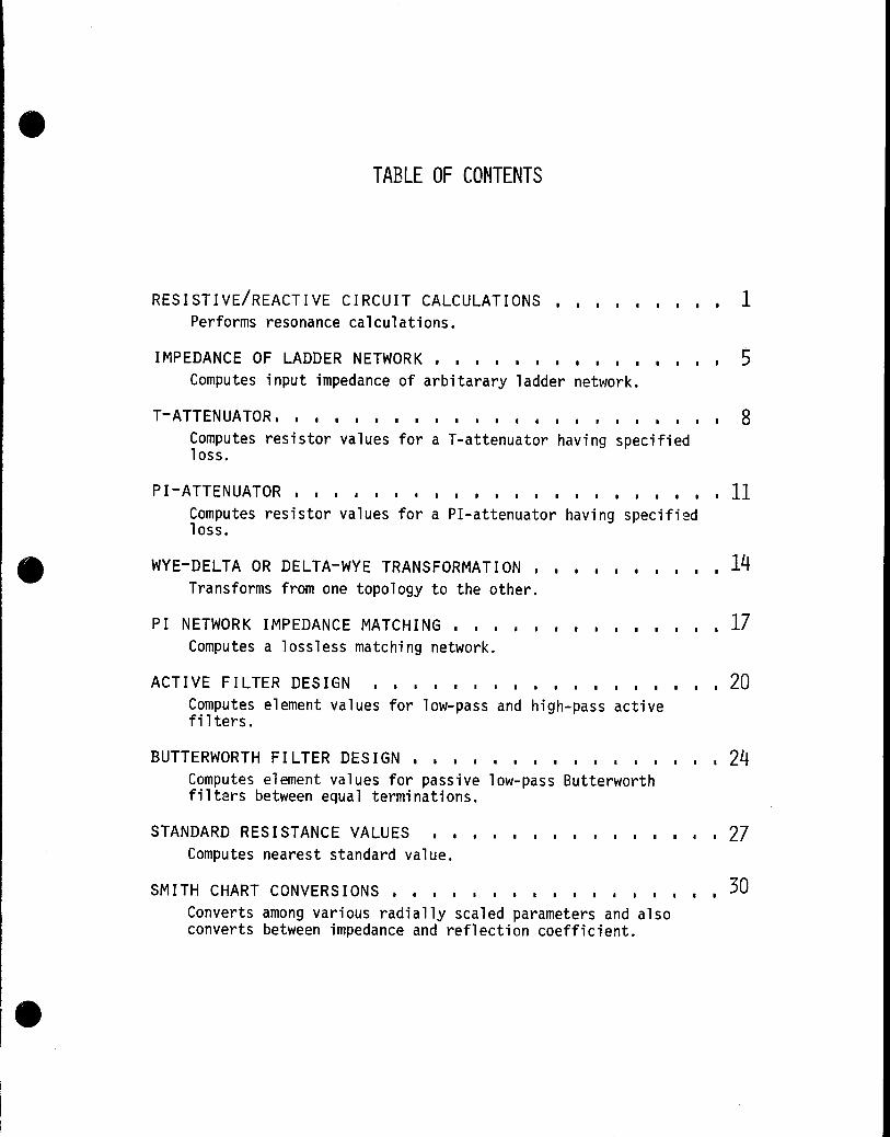
TABLE OF CONTENTS
RESISTIVE/REACTIVE CIRCUIT CALCULATIONS Performs resonance calculations.
I I I I I I I I • 1
IMPEDANCE OF LADDER NETWORK . . I I I I I I I I I I I I I 5 Computes input impedance of arbitarary ladder network.
T-ATTENUATOR. • • . • • • • • • . • • • . • . . . • . . • 8 Computes resistor values for a T-attenuator having specified loss.
PI-ATTENUATOR ••..••••.............. 11 Computes resistor values for a PI-attenuator having specified loss.
WYE-DELTA OR DELTA-WYE TRANSFORMATION • Transforms from one topology to the other.
PI NETWORK IMPEDANCE MATCHING • • . • • Computes a lossless matching network.
I I I I I I I I
I • I I I I I I
ACTIVE FILTER DESIGN • • I I I I • I I I I I I I I I I
Computes element values for low-pass and high-pass active filters.
· 14
· 17
· 20
BUTTERWORTH FILTER DESIGN .•.... I I I I • I I . .. 24 Computes element values for passive low-pass Butterworth filters between equal terminations.
STANDARD RESISTANCE VALUES • • I • I I I I I I I I I I I 27 Computes nearest standard value.
SMITH CHART CONVERSIONS ••.• I I • I I I I I I I I
Converts among various radially scaled parameters and also converts between impedance and reflection coefficient.
• • 30

RESISTIVE/REACTIVE CIRCUIT CALCULATIONS
This program performs resonance calculations for R-L-C circuits, calculates the reactance of inductive and capacitive branches, the equivalent value of series capacitors or parallel resistors and inductors,and performs power calculations for resistive branches using straightforward manipulations of the following equations:
f = - 1 r 21T/[C""""
x = 1 C 21TfC
AiA2 -- = A3 Ai+A2
where
fr = resonant frequency in hertz
L = inductance in henrys
C = capacitance in farads
Xc capacitive reactance in Q
XL = inductive reactance in Q
P = power in watts
I = current in amps
R = resistance in Q
E = voltage in volts
Ai ,A 2 = the values of two parallel resistors in ohms, two parallel inductors in henrys, or two series capacitors in farads
A3 = the resultant, equivalent resistance in ohms, inductance in henrys, or capacitance in farads
NOTE: Given a resistance or capacitance, Ai' the value of the circuit element required to produce a desired resultant resistance or capacitance may be calculated by entering Ai as a negative value.
EXAMPLES: 1. C = .Ol~F, L = 160~h.
Calculate fr
2. L = 2.Sh, fr = 60Hz Calculate C and XL at fr
3. E = 34Sv, R = 1.2SMQ Calculate P and I
4. Ri= 120Q, R2 = 240Q a. Find the equivalent
resistance of these two resistors in parallel,R 3.
b. Parallel R3 with SOQ. c. Find the resistance re
quired for a resultant resistance of 2SQ.

2
SOLUTION:
0.61-136 G5L 125,82 ... 83 :f::q
66. aeee n;~; 2.5888 r;SE2
2.8145-86 ;f.~:.f:
66.8a88 EN-:: 2.58&13 GS5~
942.4&+88 tf . .f.
c
345.138ee EN-:-: 1.25+86 G555
95.226-83 hI. P
1.25+06 bSE-; 27£.813-86 f¥f I
1a.8613& ENT; 248.8Boe G·5B3
89.888+88 t.ft R3
56.aeBe GSE ::0. :'69+ee :;:i··I. 4b
. ""-. "-" , ....
25.0(1ge E53 13?,3?+~8 :f··'f:·f 4c
T
1-I
_.-: I
3
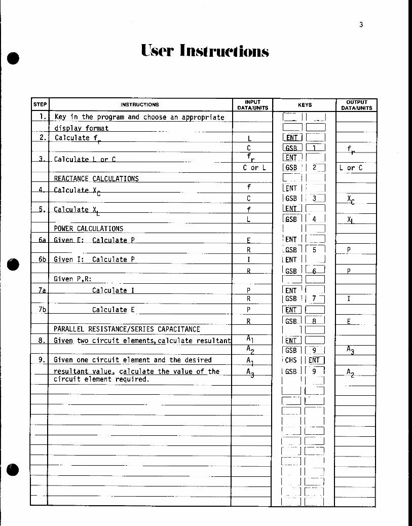
STEP INSTRUCTIONS INPUT KEYS
OUTPUT DATA/UNITS DATA/UNITS
l. Key in the program and choose an appropriate CJCJ disolav format l=:J CJ
2. Calculate f L [ENT] LJ C CGSiLJ CLJ f
3 r.ill l'uli'ltp I nr r fr lENT) L_J C or L U~SBJ [ 2 J L or C
REACTANCE CALCULATIONS C~[ ) 4 r""rll'",t~ "
f WIT] L:~J -l-
C IGSB ) O-J X~
5 Ca 1 cu 1 a t~ X. f LENT] C~ L
L [GSBJ L~~ XI POWER CALCULATIONS C~I-J
fit! Givpn F' rt!ll'ult!tp P E lEn] C"J R [GSBJ [~ P
6b Given I: Calculate P I wuJCJ R L:GSBJ l-U P
Given P,R: l_.=-.J CJ 7a Calculate I P WITJ c=J
R ~c:z=J I 7b Calculate E P [(NT] CJ
R [ill] ca::=J E PARALLEL RESISTANCE/SERIES CAPACITANCE 1- -lCJ
8. Given two circuit elements,calculate resultant Al [lNYl [- ] A? [GSIf] L9.=J A3
9. Given one circuit element and the desired A, [~HSJ [1~[]
resultant value. calculate the value of the A., CGSBJ ~l A" circuit element required. .J
CJ[~ ....
C] [_~J C----.J [-~ [=::-J em] [----l L=-J I-_-~] L~~J [-_ J [=--.J [_ .. J L==l r.ll __ J r - ... l L ---] [ . J [--] I
.' JI J
I J L J

4
o 6
.2
18
24
~J '[\' 04 G;-Or B!5 *LK2 6£ X:Y 137 fSBC
139 16
V"" V ii+-J
II ,~.·S
12 ~:LK:? 1 J ,', 14 GTDB 15 ,:LPL4
17 GSPB O(~, ., ,,·v le, ,i.,' ,'j
19 R ..... E· 26 *LBL~ 21 1 . ...-g 22 tLSL6 ~7 x'''' v ,", ... , 24 ".~ .... , ...
25 .x:
26 F. .... 'S 27 tL8:..? 28 1./X 29 *LBL8 3B ,x.'
J1 32 R··"S 33 *LBLe 34 ' 35 X
36 Pi "":'7 ,:{ ~'/
J8 1 .r,\~
39 RTN 4f *LEi..9 41 ,:.:: 42 ENT~ 42 ~NT1' 44 ! C"TV L.. __ 'j ....
45 4£ LSiX 47 + 4" '-' 49 R ... ·S
7
.3
19
25
ProgralD Listings
L or C
P
I or E
A3 or A2 t I
*** "Printx" may bE inserted or used to replace "Ri< II
REGISTERS 2 3 4 5
8 9 .0 .1
.4 .5 16 17
20 21 22 23
26 27 28 29
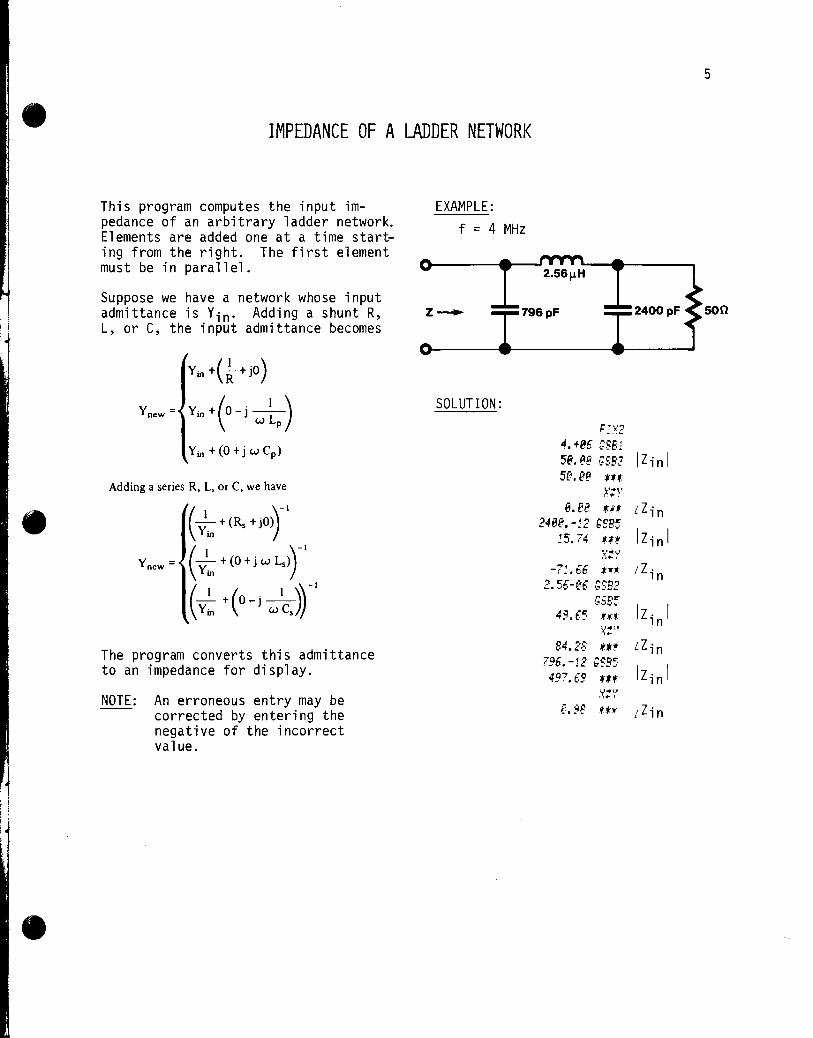
IMPEDANCE OF A LADDER NETWORK
This program computes the input impedance of an arbitrary ladder network. Elements are added one at a time starting from the right. The first element must be in parallel.
EXAMPLE: f = 4 MHz
5
2.56~H
Suppose we have a network whose input admittance is Yin' Adding a shunt R, L, or C, the input admittance becomes
z~ 796pF 2400pF soo
Yin +(~ + jO)
Y new = Yin + ( 0 - j w ~p ) Yin+(O+jwC p )
Adding a series R, L, or C, we have
The program converts this admittance to an impedance for display.
NOTE: An erroneous entry may be corrected by entering the negative of the incorrect value.
SOLUTION:
F:X2 4.+86 ;851 58. Be ;SB? I Zi n I
B.te *~t LZin 248f'.-12 f~P.~
~5. 74 u* IZ in I ,\":~r
~f ~~
tw:~· LZin -r •• t.t.
2.S6-f'6 GSB2 GSB5
IZin I 49.(.5 :f.:f:.:
X::-' 84.2B Ut LZin
796.-12 ;SB5 IZ in I 497.69 U.t
'x'.U ,·, .. i
r (jO - I _0 \,. .f:.f:) LZin

6
STEP INSTRUCTIONS INPUT KEYS OUTPUT DATA/UNITS DATA/UNITS
1 Kev in the Droaram and choose an aDDroDriat~ CJCJ rlicnl::llv Tnl"m::llT c=JCJ
L:=JC] 2 Tnitialize f ~CD w
r=JC] t 3. Input a parallel element: [_~c=J
Rn ~s:[] [3 1 Ilinl Ix++yl C~ LZin
Co [G£sJ ~1 II;nl [i<;;il c::=J din
L .... [GSJU [} J Ilinl t
~++yj c=J Llin 4a For a series element: [==:1 L~
R~ llial O~ .. [~SR ] D:=J Ilinl I x++i'] L=:J LZin
CS IGSSJ [IJ ~LD Ilinl I x++yj CJ LI;n
Ls_ lliBJ [2 J [GS~J IT] Ilin l t:L~C~ LZin
All for a oarallel element· CJc=J Go to step 3 L ~ c::=J
[~CJ ~ R~n~:.It ct~n 4 IInti 1 :.Ill ~ 1 F>m~ntc; arF> F>ntF>rF>d c::=J C~
c=JCJ C_~] c=J c::=J CJ
, [ lc=J r--l [-] I
t r--] l-~
- ---- -
[=--J C-~ [ __ -J [-=~J [-]CJ [-~ J r~~ l _ -][--j
-- ~.---
I ---I [--J
I -- _- J L I

PrograUl Listings 7
81 *LBU f 58 GSB8 Convert Yin+lin 62 2 51 RJ. r.7 y 52 .~CL6 84 p' t~ + Add admittances , I ~,j
85 x Clear flag ~4 ~'-'''' or impedances ..... 86 ClRG w "it Rei..? .... ,}
f7 STD3 56 + 88 R/S 0::., x:", ,.' !
89 tLBL@ l+-+Y '58 RCi..0 18 ~·l· 59 :#8'? 11 -tt' 68 ;588 12 ux ~f t .. RJ· Convert l+Y 13 X:~' 62 STDl 1 A ." CHS 63 X-. V .. , 1'5 V-'\'
Ii ... 64 ST02 16 -tR 65 x:", i., 13
~~ 8 J" t,e
18 RTN R,C,L 57 GSB8 Convert Y+l 19 tLBl2 Set flag (series) 68 ST08 Clear flag 20 ST08 69 R~·
21 R"S 78 ~p
22 f:LBLJ ", p.· .. ·s i l
Ilin l *'k* Ll in 2'3 l/X 24 RCLB 25 X=8?
a,Y (parallel) " .- P08 ~tl
27 8 28 HOB 29 *L8L4 a,l (series) 38 RCLJ 31 x ?2 1/:1 Xc or BL 33 CHS 34 8 ~r:: .j., :-;;y 36 GraB 77 -.Ji tLPL'5 38 RCL-J ~o .r.' XL or BC j_ ..
40 13 41 g:'r' 42 :I-LBlB 43 STC7 *** "Printx" ma~ be inserted. 44 ".,.,.
l;" !
4'5 ST06 46 pr·; " .. {,..~.:
47 ReL! 48 ReLO 49 XIOr;
REGISTERS 0 flaq 1 Re[Y;nJ 2 ImlYin] 3 w=2'ITf 4 5
6 used
7 used 8 9 .0 .1
.2 .3 .4 .5 16 17
18 19 20 21 22 23
24 25 26 27 28 29
8
T ATTENUATOR
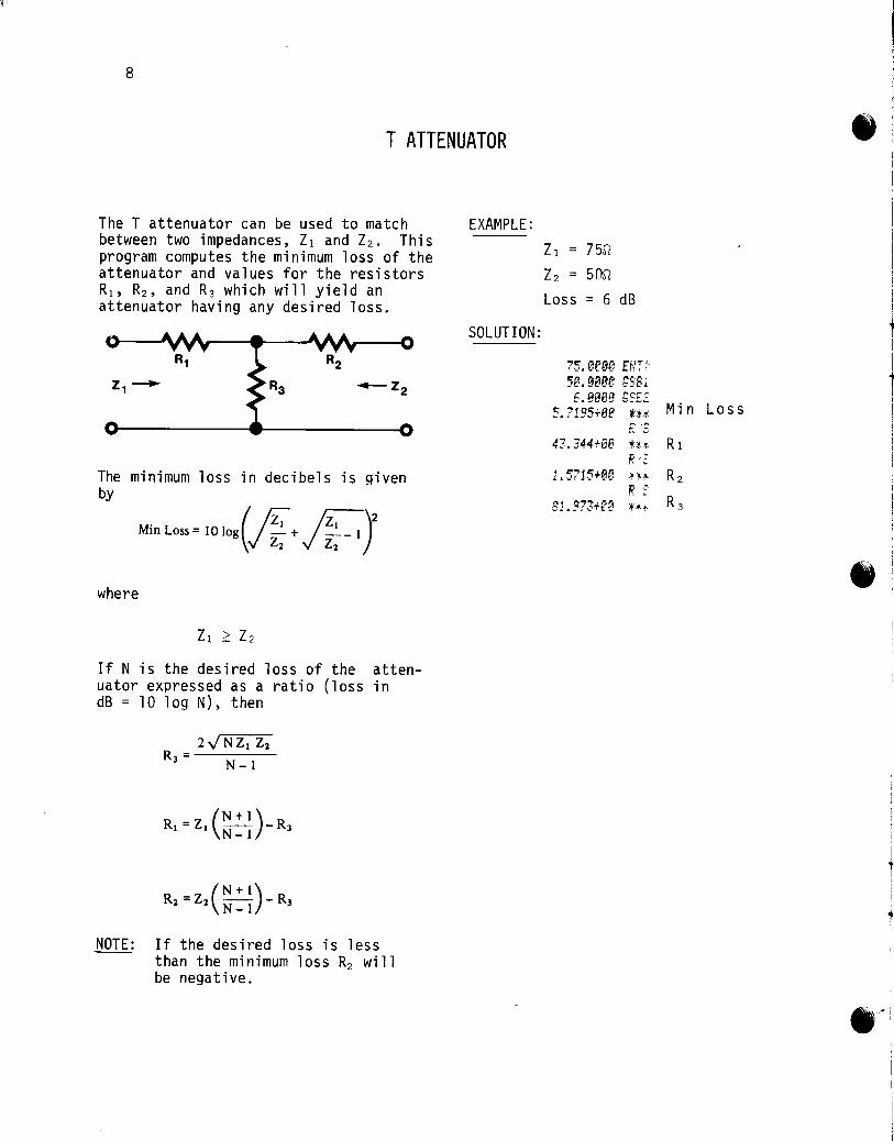
The T attenuator can be used to match between two impedances, ZI and Z2. This program computes the minimum loss of the attenuator and values for the resistors RI , R2 , and R3 which will yield an attenuator having any desired loss.
The minimum loss in decibels is given by
Min Lo" = 10 'o.(h + ,;r-:)' where
If N is the desired loss of the attenuator expressed as a ratio (loss in dB = 10 log N), then
(N+ 1) RI =ZI -- -R3 N-l
NOTE: If the desired loss is less than the minimum loss R2 will be negative.
EXAMPLE:
SOLUTION:
ZI = 75rt
Z2 = 50rt
Loss = 6 dB
75.er38 EN;: 5e.3~ee GSBl 6.0BM t;SE~
5. ?19S"'BfA ~:.;:.¥: Min Los s 1"" ......
t,,· ~,
.~ 'T: .• 344+00 i:.;'.,. R I P.. -~
1 5715+00 .~ :'··f· R 2 P. -
o·
81 973+fe * .... ;. R 3
t I
I
e·~i

9
STEP INSTRUCTIONS INPUT KEYS OUTPUT DATA/UNITS DATA/UNITS
l. Kev in the Droaram CJc=J [=:JCJ
2, Enter impedances Zion [ENT J 1_._ I Z~ 0 [£SL] [CJ
L-~] [ ] 3, Enter desired loss and run Loss, dB [GSBJ CD Min Loss,
(Tf Mi n I ne:e: > nl:le:i V'l:In I ne:e: ~nt~V' '" c-~-=:J [_---=J db new Desired Loss) [-J [--- I
-- ------
[~ I [--- -1 4 Ol/tOl/te:' [Bl-s_] [-] R1 , n
1-- --ll-l R/S -- R • n [R/S 1 r -~J
- . -- R~ n f_-J[ I [ - - -] [ - _ _ J
[ II - 1 [ 1[_ ] I ] [ --I [ " I [ I I -]
[ II I [ II I I Il I [ I [ I I I [ I [ Jl I [ I [ I I II I l ]1 I [ II I t It I I I [ I I I L I I I [ j [ II I I II I I II I I It I I II ] I II J

r!1
10
1'>' :f:LBL! t:: • ,~.-,
t:iL EI{~4
63 c-~~." ,-·f;"!,,;:,
@4 X:Y a5 C-T"l
j '_'.i.
@6 "",c-........ ' ~., tLBL2 ~" 88 fP ,-," e If .. 1 flii J.J.
12 STu? ~3 ':~ ..
f • .'1 X 1~ IX 40 ... ' . ~ It: ;;::
17 18 P""'''' "L.LI ,~
~ _7
2i? ST+? ~.
"::'.1.
".~. SiD8 ;;;;,..::. ."~ :.:.: 24 STDS .,~ RCL! ... .;
26 peL: 27 x ~'-:I .::.c PCL8 29 :m RCLS 31 -'l STO? ";I~
77 RCL2 ....... ' 34 RCL7 71:: ... ' ... ' 7~ ~·t RC;.8 .. .,. ";:j
~..,
..;e RCL~ 33 4f STC4 41 ReL1 .. " '1';;'
p"': ~ .·.L·~~
43 44 Etift 45 IX 46 V·',,! : .. ~. 4~
4° I..i
49 rv ", r,
0
6 Min Loss
.2
18
24
PrograUl Listings
N
Zl 2 Z2 7 N N+l 8
N-l .3 .4
19 20
25 26
5e + 51 ;:{'i ~.., LC:; __ '''::'
~7 ,-'--' r:A e •• .i",.
55 x 5[ c--r"lC .... ';'..;,.,
C:., R"C-.. '-' *** Min Loss ~~l PCi.3 ..ie· 59 P/S
*** Rl fB RCL4 ~. R.··S *** R2 0.
62 RCL5 63 R/S *** R3
*** "Printx" may e inserted or used to replace "R S".
REGISTERS 3 R, 4 R? 5 R~ 9 .0
.5 16 17
21 22 23
27 28 29
~
-

PI ATTENUATOR
The PI attenuator can be used to match between two impedances, ZI and Z2. This program computes the minimum loss of the attenuator and values for the resistors RI, R2, and R3 which will yield an attenuator having any desired loss.
The minimum loss in decibels is given by
If N is the desired loss of the attenuator expressed as a ratio (loss in dB=10 log N)~ then
EXAMPLE:
SOLUTION:
ZI = 75D
Z2 = SOD
Loss = 6dB
7S.eeee st'.eeee 6.aeoe
5.71~'5+8e
i:.3ef.2+!3?
8£.:17+e~
45. 747+88
11
EN7"i G5S1 GSZ'2
t:'.:t Min Loss F.:5 lH R1 R< H·t· R2 F..' ··r
~.
h.f R3

If!' ,
12
STEP INSTRUCTIONS INPUT KEYS
OUTPUT DATA/UNITS DATA/UNITS
l. Key in the program CJc=J c=:J c=J
2 Enter imnpcii'ln("pc; Zl, [ENT] CJ Z2, ~[IJ
l __ J C:J 3. Enter Desired Loss and run Loss, dB l~~CD Min Loss,
(If Min Loss>Desired Loss, enter a new L~[ 1 dB Desired Loss) c::J L~
c::J ~J 4. Outputs: LBLSJ c=J R1,rl
rnmc~ R2,rl
ffiZu L _~ R3 ,rl [- JL~
[ ~ c::J c:=J [ ___ :J C_:=J L::J CJc::J
IJI C~ c::=J CJc=J C=J [-=::J C~ c::=J CJCJ c::JCJ [ -] c::=J c::J c=J c::=J L=:J c::JCJ c::JCJ CJCJ c=Jc=J [ ~CJ CJ c::J CJ c::=J C]C~ C~L 1 [---=-:J L:=J [-u] [- ]
I_~_- J C-:-J r-_J l J

ProgralD Listings 13
81 *LBU 58 )<2
82 EHG4 51 LOb 8J 5T02 52 1
84 g:y ~'7 ... 1"" B
85 STOl 54 x
86 R/S 55 5;06
e7 *LBL2 56 R/S *** Min Loss 88 1 57 RCD 89 8 58 R/S *** R1 18 59 RCL4
*** R2 11 18)( 68 R,·'S
12 HOl N 61 RCL5 *** R3 13 62 R/5
14 x 15 J"Yo 16 RCL? 17 .
l
Ie ST+7 19 -2e 5r-:·7 21 ...
.:. ?, ."-
23 x 24 5T05 R3 2~ UX 26 5108 27 RCL? 28 RCLl 29 38 ,'?CL8 ~f j~ -32 UX ~'7 5T03 R1 :;-
34 RCL7 35 RCL2 36 ~7 J, ReLe 38 -39 1/)< 48 5T04 R2 41 RCLt 42 RCL2 43 -44 IX 45 LSTX 46 f
.L
47 -48 IX 4? +
REGISTERS 0 1 Zl 2 Z2 3 Rl 4 R? 5 R~ 6 Min Loss 7N,~ 8 1/R3 9 .0 .1
.2 .3 .4 .5 16 17
18 19 20 21 22 23
24 25 26 27 28 29

If"
14
WYE-DELTA OR DELTA-WYE TRANSFORMATION
This program performs the Y-6 transform for circuits consisting of resistors, inductors, or capacitors*.
The Y-6 transforms for one-of-a-kind elements are summarized below.
116" Topology
"Y" Topology
For Ca~ac itors:
Y-+6 Ca Cm
C1 = ---rc--Cb Cm
C2 = --yc-
Ck Ca Cb =~
EC = Ca+Cb+Cm
6-+y Ca = LeC c;-
Cb = LCC c;-
Cm = ECC c;
ECC= C1C2+C2Ck+C1Ck
* Adapted from HP-67/97 Users l Library program #00404D by Bruce Murdock.
For Inductors: (and Resistors,replace LiS by Rls)
Y-+6 L 1 = tLbL
L2 - ELL - """La
L - ElL k - Lm
ELL= La Lb+Lb Lm+La Lm
EXAMPLE:
45.75
L = L1Lk a -U
Lb = L2Lk U-
Lm = L1L2 EL
EL = L1+L2+Lk
2386.2 86.52 -SOLUTION:
2386.28 ENTt 45.75 ENH 86.52 1;581
1;582 1;584
43.35 *** R/S el.98 H*
R,···S 1. 57 ***
43.35
81.98
1 k 2
a
m
b
1.57

15
STEP INSTRUCTIONS INPUT KEYS OUTPUT DATA/UNITS DATA/UNITS
l. Key in the program and choose an appropriate c=J[~
disolav format c=JCJ ~1~1
2. Enter elements for Y or 6 a or 1 [lliCJ L_~ m or k [(~r] [~ b or 2 [GSB_J [f~l 0
[~-~ l -] - -- . ---
3a For inductors or resistors IGS~~] r-_~-~ I 1 r-- -] r-- -]
3b For caoacitors ao to steo 4 r- J [ . I I~ --1 [. _]
4a For Y-+6 [GSBll-j-] element 1 I_I[ I element k I II I element 2
4b For 6-+Y IGSB II 4 I element a I II I element m I I I - I element b I I [ I I I I I l I I I [ Il I I I [ I I II I I j l I I Jl I [ j [ 1 [ II - I [ II I [ . II I I I [ I [ I [ I [ I [ I [ I [ I [ I [ I I I [ -I [ I [ I I II I I I [ I I I [ I

16
el *!..BLl l!2 S![I?
~? ~J
134 ST02 1?5 p.J.
B6 CT!'11 ".': ~'''-
&? e e~ .•. STOe 139 RiS 1~ t.LBL2 ; 1
f .-; STOfi ... .:
~? Pi'S 14 *LBL~ 1.:- ReL& · ~ 1 t, x>&'" 17 Groe ~c *LBL9 .i. ,_
19 Ir/ l .,l.:-..L
2(3 Pt:..2 ':'1 + .:...
22 PCi..3 27 + 24 STI]4 25 RCLl 2.5 PCL2 2? x 28 R[L4 29 J~ STOS 71 ReL! ... '''' ,.., -5,: RCL3 33 x :34 RCL4 7~ ~',,-l
7~ .·b 8TO€-77 .'1 RCL2 ?8 PCLJ 39 x 4[< PCL.! ~1
42 ST07 .n · ' ... ' t;T!J8 44 *LBL4 45 RCL0 46 .~;>8?
47 r.rC~ 4 c, · ,_, .LBU? 49 1;'(" •
.,\..'1...
0 flag 6
k or m 7
.2 .3
18 19
24 25
Program Listings
1
2
Clear flag to indicate capacitor
Set flag to indicate inductors or resistors Y+~ for capacitors
or ~+Y for resistors and inductors
Sf PCL2
S2 ~CL2
56 ReL:
58 x ~c + £~ STi)4
6"! ST05 54 RC!...4 65 '?CL2
57 STD6 68 RCL4 6~ ReLi
71 8TO? 72 ~:!..K8
"5 pelt n R/8 77 PCL7
Output *** 1 or a
*** k or m
*** 2 or b
~+Y for capacitors or *** /lPrintx/l may r~place /lRIS/I.
Y+~ for resistors and inductors
REGISTERS
or a 2 k or m 3 2
b 8 9 or .4 .5
20 21
26 27
or () 4 2: or 2:2: 5 1 or a .0 .1
16 17
22 23
28 29
-
• I
• ,
PI NETWORK IMPEDANCE MATCHING
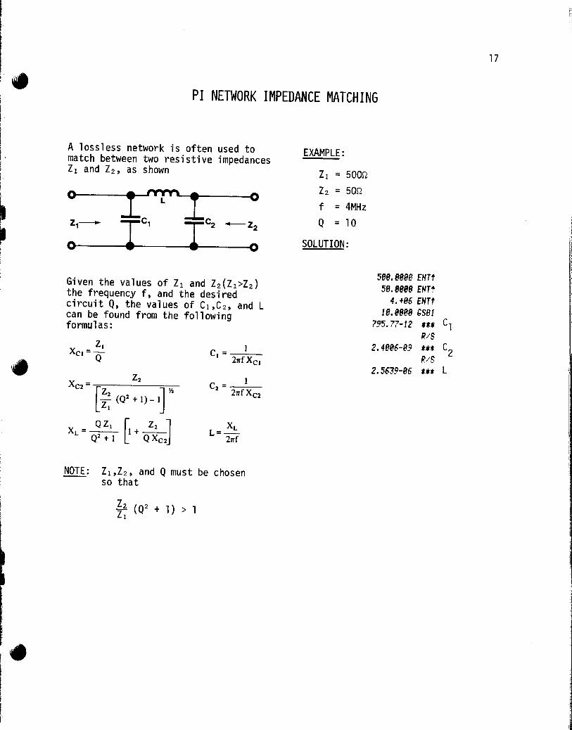
A lossless network is often used to match between two resistive impedances Z1 and Z2, as shown
0 l"f'"'l 0
Z1- Ie, Ie, -Z2
0 0
Given the values of Z1 and Z2(Z1>Z2) the frequency f, and the desired circuit Q, the values of C1,C 2 , and L can be found from the following formulas:
z. XCJ=-
Q 1 c.=---
21TfXCJ
NOTE: Z1,Z2, and Q must be chosen so that
I£ (Q2 + 1) > 1 Z1
EXAMPLE:
Z1 = 500n
Z2 = 50n
f = 4MHz
Q = 10
SOLUTION:
588.888B ENTt 58.8888 EHTt
4.+86 EHTt 18.8888 GS81
795.77-12 Ut
R/S 2.4886-89 Uf:
IUS 2.5639-86 t**
17
C,
C2
L

18
INPUT KEYS OUTPUT STEP INSTRUCTIONS DATA/UNITS DATA/UNITS
l. Key in the program c=:J c=J c=Jc=J
2. Enter variables and run [- ] [ -]
Z, .rt l1NIJ c:=:J Z2,rt rmJC.] f,Hz LItIT] c=J 0 ~saJ [ 1 ] C 1, F
[]ill c=J C2,F WSJ C-] L,H c:::=J C I c=JL~ C~c=J L-=-=:J C~ C=:J [==:J [ J c=J c=JL~ r Jc=J c:::=J c:::=J c=Jc=J CJc=J CJ c:::=J r- ] c=J CJ[=:J c=:J c=J L __ J c=J c=Jc=J CJc=J CJC~ CJc=J c=Jc:J l-=-~--=-l c=J c=JL_~ [ __ l C-] [~--=J L_~ ,-.-=] CJ [--~l L=::=J L --]C~ I - _.1 L ___ ]
I --. .1 [- .. ]

I"
i
r i I I I
0
6
.2
18
24
81 tLBLl 82 Sfll4 83 IN 84 5T03 8S N 86 5T02 87 RJ. 8e STal 89 EH~4
18 RCL4 11 PCLt 12 13 r,S88 14 RCL2 IS RCLt 16 17 PCL4 18 X'i 19 1 28 + 21 STOS 22 )( ,'7 ! ~~, • 24 -25 IX 26 RCL2
'"' ~( . 28 ST06 29 ~S88
38 RCL2 31 RCL6 32 .If
33 RCL4 34 35 1 36 + 37 RCL4 3e RCL! 39 )(
48 RCL5 41 42 )(
43 tLBL8 44 Pi 45 2 46 .If
47 RCL:: 48 x 49
1 IX,...,
ProgralD Listings 19
58 R/S ***C 1 ,C 2 ,L ~1 PTH 52 R/S
l/XC 2
REGISTERS 1
21 2 Z2 3 f 4 Q 5 Q2+1
7 8 9 .0 .1
.3 .4 .5 16 17
19 20 21 22 23
25 26 27 28 29
20
ACTIVE FILTER DESIGN
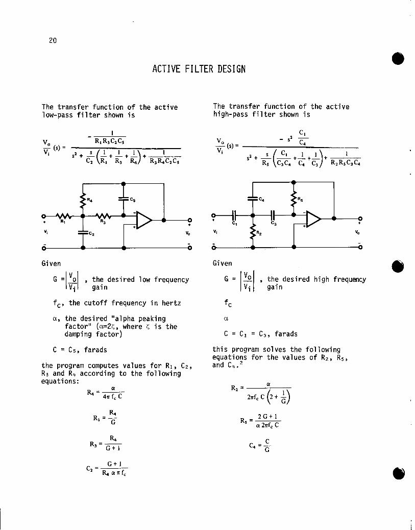
The transfer function of the active low-pass filter shown is
+
Vi
Given
+
, the desired low frequency gain
fc' the cutoff frequency in hertz
a, the desired "alpha peaking factor" (a=2i;;, where i;; is the damping factor)
C = C5, farads
the program computes values for Rl, C2, R3 and R4 according to the following equations:
It. R3=-
G+l
G+l C ----
2 - It. Q rr fc
The transfer function of the active high-pass filter shown is
Given
+
G = IVo Vi
, the desired high frequency gain
this program solves the following equations for the values of R2 , R5 ,
and C4 •2
Rs = 2 G + 1 Q 2rrfc C

J
i' I I ,
NOTES: 1. If a is not specified, a=/2 -- is used, giving component
values for a Butterworth filter.
2.These equations derive from the fact that both transfer functions have the form
EXAMPLES:
-G w 2 c
1. Compute R4, Rl, R3, and C2 for a low-pass filter with
fc = 100 Hz C = .1~F G = 10
a = ff
2. Compute R2, a high-pass
f c = .1 Hz C = 1011F G = 1
a = ff
C4, and Rs for filter with
SOLUTIONS:
21
FIX2 188.88 ENTt 8.H3€ ENP-18.88 EHTt 2.8& (I;'
"
/;S81 112~3. 9~ *H R4
P-E-1125. 4e *~* Rl
F'C' 1023.89 tt. R3
/(.C ...... !
2.28-&6 U~: C2
8.18 ENTt 18.-66 ~I'T.f-
~.l ••
1.8e ENTt 2.88 IX
/;SB2 75826.36 *u R2
R.·· .. S 1.88-85 .:tt C4 R/S
337618.62 u.: RS

22
INPUT KEYS OUTPUT STEP INSTRUCTIONS DATA/UNITS DATA/UNITS
l. Kev in the proaram and choose an d 'iate CJc=J display format c=Jc=J
[:=J CJ 2 Enter desian Darameters f c:' Hz COOJCJ
C. F WIJC~ G [ENTl ~ a. c=J [==:J
3a For a low-pass filter []SBJ [LJ R~,n
[lli]~ Rpn
nr LRjSI c=J Rs,n [ili]~ C2 , F
3b For hiah-Dass filter [[sru [IJ R2 ,n em] L-=:J C~,F
CRZSJ [ ~ Rs.n ~~ ~~ i-lc=J c=Jc=J ~~ ~~ c=J~ [ ~~ ~c=J c=Jc=J ~~ c::::J c:=J ~~ c=:::J ~ c=:::J ~ CJCJ [~c:=J ~c::=J c=J c=J [==:J [==:J [- -] c=:::J C~ [==:J C~[~ L_~[~ [==:J C~

ProgralD Listings 23
81 ~:LBL1 58 02 ~'r'i" 51 /\1/5 *** R2
.. ,~:I
0? RJ· 52 /\IeLf 84 PJ· 53 PCl5 85 5T06 S4 ST-:? 86 x 55 IF Pi 56 R/S *** C4 _ J
88 x 57 PCl? 139 4 c:o 1,·-\r' ,.''''' - .. 18 x 59 R/S If *** Rs " . " R/S l~
*** 13 STD4 R4 14 g~" .. T 1r . ~, 16 P..-'S *** Rl 17 PCi..4 " J
18 LSTX 19 1 28 + 21 '-,"'i. P.lS *** R3 ~c.
23 LSTX 24 peLf 25 x 26 4 .,~
c.{ ~.
28 pel7 29 >12 38 31 R.lS
*** C2 32 tL8L2 33 STO? 34 R4-35 5T05 36 P,J-77 ST06 ... " 38 x 39 2 4e x 41 Pi 42 x 42' STx7 44 PClS 45 1/X 46 " .;;
(2 G+l)/G 47 + 48 ST-=-{ 49 )(
REGISTERS 0 1 2 3 4 R4 5 G 6 C 7 8
2 G+l 9 .0 .1
('Y.
.2 .3 .4 .5 16 17
18 19 20 21 22 23
24 25 26 27 28 29

24
BUTTERWORTH FILTER DESIGN
This program computes component values for Butterworth low-pass filters between equal terminations given filter order, termination resistance in ohms, and corner frequency in hertz.
C. = _1- . (2i - I) 11" • 1 3 5 I sin , 1= , , , .•.
rr fc R 2n
L - R . (2i - 1) rr . - 2 4 6 i - -f sin , 1- , , , ...
rr c 2n
Odbl-----.....::
20 log ~n
+-----------~--~-I~I
NOTE: n ~ 10
EXAMPLE: n = 6
R 50Q
f = 10 MHz c
SOLUTION:
6.8888 58.8888 18.+86
1. 8888+8e
164.77-12
2. 8888+e8
1.1254-86
3.8888+88
614.93-12
4.8888+88
1.5373-86
5.8888+88
458.16-12
6.8888+88
411.92-89
HIT"f" ENTt SSP! It** i R .... S ltU Cl R··· .. S tH R/S t*' (( .. ·'S tt,: R/S ttt R.···-S tU R/S t** R .'''' tU ((/S
ttt R.··S u* ((/2
t**

I
t j
I I~
STEP
l.
2.
3
INSTRUCTIONS INPUT
DATA/UNITS
Key in the program
Enter filter parameters n R,n fe,Hz
Run
25
KEYS OUTPUT
DATA/UNITS
CJ [=-:=1 t=Jc=J [ENfl L ___ I WIT] [I 1- --1 [~J
--- ... -. -~ - -
r~_J [--~J
IGSlfl [ L __ j i =1 LRL~ I r _ --- I Ci,F rR/S I I- I i=2 [RIS J [ J Li ,H [. ·1 [ 1 r • I [ I [_" __ I [ I [R/S II j i=n [R/S II I Ln or Cn I R/S I [ I 0
I I [ I [ II I [ I [ I [ I [ I I II I [ I [ I [ I [ I I II I I II I I II I [ I [ I [ I [ I I II I I II I I II I [ I [ I I /I I I II I I II I I II I I II I I II I I I [ I

26 ProgralD Listings 58 CHS
81 t.LBU ~1 ST.4 82 RAD 52 rx 83 ENG4 53' SX.5 84 ST. 3' 54 ISZ 8S RJ· 55 GT09 86 ST.2 56 t.LBL8 87 RJ· 57 8 88 ST. 1 58 R/S 89 ST08 18 *LBL8 11 RCL8 12 2 13 x 14 f .. IS -16 Pi 17 x 18 RC.l 19 2 28 x .,1 ~ .. Sine argument 22 STOi ,,~
c.J DSZ 24 GT08 2~ Pi 26 RC.3 27 Pc. 2 .,0 x a:..,-:
29 x 3C !/X l/nfeR .Jl ST.5 32 2 J3 CHS 34 ST.4 35 1 36 STOe 37 tLBL9 38 RC.l 39 RCL8 i>n? 41." X) 'r") 41 GT08 end
*** i 42 P/S *** "Printx" may r~plaee "RIS". 4J RCLi 44 SIN 45 RC.5 46 x 47 R/S *** Ci or Li 48 pc. 2 R 49 RC.4 + 2
REGISTERS 0 i 1 2 3 4 5
6 7 8 9 .0 .1 n .2 R .3 fe .4 +2 .5 l/nfeR or ~fe 17
18 19 20 21 22 23
24 25 26 27 28 29
\-

I' i-I
STANDARD RESISTANCE VALUES*
For a given tolerance, a "step size" is computed which is used to determine two values, one below and one above the non-standard resistance. These are converted by a subroutine to standard values, and the geometric mean of the latter is calculated. If the given non-standard value is below the mean then the lower standard value is selected; otherwise the larger value is selected.
NOTE: Incorrect results will be obtained for tolerances other than 5%, 10%, or 20%.
REFERENCE: International Telephone and Telegraph Corp. Reference Data for Radio Engineers, fourth edition, p. 78.
EXAMPLES: Find the closest standard values for the following: Rl = 432st
R2 = 114 Kst
R3 = 3.5 Mst
* Adapted from HP-65 Users' Library program #00915A by Jacob Jacobs.
SOLUTION:
EN;;.: ~.JPBP GEE: 5%
432.8886 :?5E;; 43e.e9+e~ 'j~ R~
~14.+0J GEE;; ~te.ee+BJ ~:H R~
J.~+86 GEE;2 , J. 6ei38+86 t.·:~ R 3
4:2.e~e0 GSE2 470,88+gep·
~!4.+&3 ~SE;:
:2~, 813+8: ;:.H
26.88813 bSE~ 4:'2.8888 GSE2
478. 8e+el! ~H~
114.+83 GSE2 1 fe. e8+f2' l· f·
R~
20%
R't
R~
27

28
STEP INSTRUCTIONS INPUT KEYS
OUTPUT DATA/UNITS DATA/UNITS
1 Kpv in thp ~-~,.~,~- and c:hnnc:;e an aLlLJ ..,L 'i ate CJ[:=J 1'I;.,nl;o\l ofn ... m;o+ c=:J c=J
-J
c=JCJ 2 Fntpr tnlpranc:p (~ln. nr 2n) T% []S[] o::::J
CJ[J 3. Enter non-standard resistor size and compute R,~ L_GsBJ UJ R~~
nearest standard value C-=:J C 1 c=J c::=J
4. Chanqe tolerance at any time by Qoinq to steD 2 c=J C-] C~ C-::J c=JC~ C~r=J [- JC~
[--=J [=---::::J [--=:J [~=:J C~L]
I [=Jc=J L~~I [=::J c:=J c=J c=J[~ CJCJ [ ~ C=:J [---] [-=:J --- ---
[~-=::=J [==:J l-=~ l=:J C-] L--=:=J [-~ [:=J C-=J e.=J c=Jc=J [-~ [----]
l=--l l =.J ---- -[ ------ j L--~
- ----- - -- - --"- --
[=--1 L~~ l_--J [=~l [
- -- J l--=J [
--
1 l=-=-J l 1 [ _____ ~ I [ 1 [ -] I - J L 1

ProgralD Listings 29
58 x 10 EXP R7 81 .L8LI 51 P/8 82 f
52 tLBL8 *** R J
83 2 ~7 Finds standard R "' .. : . value from multiple B4 C 54 5 85 55 + of step size
86 18)( 56 INT Round 87 ST02 lOtol/120 up ~7 STO( 8F p ..... S ... :j
1;0 2 89 tL8L2 ",1,-;
59 6 18 LOG 68 , .. , vn
11 ENTt i,/ I:·
61 GT06 12 INT 62 4 13 STa4 63 7
14 -64 RCL6 15 1 65 x>r" 16 + 66 br03
17 18)( 67 1 26<R<47 then add 1 18 ST03 68 + 19 1 69 RTN 28 ST-4 78 tL8L3 21 1 71 8 I •
22 8 72 3 23 ST05 ?J ReL6 24 tL8LO 74 XIr" 25 RCL3 7~ RTN f ",:
26 PCL~ 76 '3 This step > 27 .'O·y" ~~ 2 Normal R? (( .,0 GTa9 78 RTN &..\ • .'
29 PCL2 79 .1:LBL7 30 x 88 RCL6 31 ST05 81 ST07 32 GTOO 82 PTN J3 tLBL9 83 fLBL6 34 GSE'8 84 RCL6 35 ST07 This step 85 PTN 36 1?CL5 86 p····S 37 RCL2 38 39 GSB8 48 STa6 Last step 41 RCt? *** "Printx" may t e inserted. 42 x 4J r·:' /(Thi s step)*(Last 44 PC!.? step) 45 VL"" 0_' 46 GSE'7 47 RCL7 48 1?CL4 49 10)(
REGISTERS 0 1 2 Step size 3 Norma 1 R 4 Exo of R 5 Thi s steo 6
Temn 7
Temn 8 9 .0 .1
.2 .3 .4 .5 16 17
18 19 20 21 22 23
24 25 26 27 28 29

30
SMITH CHART CONVERSIONS
This program allows conversion among standing wave ratio, reflection coefficient, and return.
The parameters
o = voltage standing wave ration
SWR = standing wave ratio expressed in decibels
p = reflection coefficient
R.L. = return loss
are related as follows:
C1 SWR P R.L. SWR = 20 log 0 00 00- -1.0 -0
40. 40. 30.
20. .00 1.0
10. 20. .80 2.0 R.L. = 20 log t
15. .70 3.0
5.0
4.0 4.0 .60
5.0
10.
1 + p a =--1 - p
3.0 .50 6.0
8.0 7.0
• 40 8.0
0.0 2.0 6.0
• 30 10 •
1.8
12. 1.6 '.0
.20 1 ••
1.'
2.0 1.2 .'0 20.
25.
1.
These relationships are perhaps more clearly seen in this sketch:
R.L. tJ p a a [j SWR
20 Iog-j, 1-p 10 20
The program also converts between impedance and reflection coefficient using the following relationships:
and
~ -I r=pL~= _Zo=-__
~ +1 Zo
Z =ZUJ=Zo~ I-r
where r = complex reflection coefficient
p = I r I cp = LI
Z impedance Z Izi 8 LZ
Zo= characteristic impedance
EXAMPLES:
1. Convert a 6 dB SWR to o .
2. Convert a 7 dB return loss to SWR
3. A 50~ system is terminated with an impedance of 62L37°. What is the reflection coefficient?
4. A reflection coefficient of .5t7°is observed in a 72~ system. What is the impedance?
SOLUTIONS:
STEP
l.
2.
3
4
Lo---..
6.08 GSB4 2.88 Ht. a 7.ee GSfJ
G586 ("C'C'" :.:'--.... ~
8.?~ tU SWR
58.88 STal J7.8fJ ENTt 62.80 f;SB8
0.?'5 ·f:U p
INSTRUCTIONS
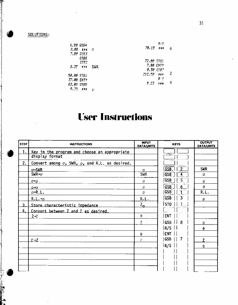
Kev in the orOQram and choose an aoorooriate di sp1 ay format Convert among a, SWR, p, and R.L. as desired. a-+-SWR SWR-+cr
a-+-p
o-+a
p-+-R. L.
R. L.-+-o Stnrp r.harar.tpric:tir. imDPcianr.p
c Z and r as d~sirpd z-+-r
r -+-Z
R/~
78.19 ·Ut ¢
72.80 ST01 7.88 ENTt 8.Se r;sp:
212.'5(1 .t.t. Z R··S
~,2J .·.U e
INPUT KEYS DATA/UNITS CJCJ c=Jc=J c=J l __ I
a CGSB:J [ 2 ~ I SWR r~S~] [~J
a rGSJtJ [~] p [Gsa] [ . 6_~ I p lcr~B-1 r~l- .. I
R.L. r~sl~ I r~j I Zn rsfoJ L 1-]
[ -][~ -]
e rENT I r . I "Z ~ GSJLJ I 8 I
IRis II 1 cp lENT II I r IGSB II 7 I
I RIS I [ I I II I I II I I I [ I I II I
31
OUTPUT DATA/UNITS
SWR C1
p
C1
R.L.
p
p
cp
z e
~ -.--

32
81 fLBU 82 1/X 83 tLBL2 84 LO(; 85 2 86 8 87 x 88 R/S 89 tL8L3 18 CHS 11 tLBL4 12 2 13 8 , A .'1
15 18x
16 R.'S 17 tLBL5 18 I/X 19 CHS 28 tLBL6 21 1 22 x:r 23 + 24 1 25 LSTX 26 -27 28 R.,'S 29 tLBL7 38 f • 31 ST05 32 RJ. 33 (;S88 34 RCU 35 CHS 36 x 37 +R 38 +P 39 R ... 'S 48 x:r 41 R/S 42 tL8L8 43 RCU 44 CHS 45 ST05 46 RJ· 47 (;588 48 R ... 'S 49 x:r
0 1
6 7
.2 .3
18 19
24 25
ProgralD Listings P-+R. L. 58 R.·'S *** cP
51 tLBL8 IlL cr-+SWR 5" .. +R Re Im
53 ST04 54 x:r 5'5' ST03 56 x:r
*** R. L. or SWR 57 RCL5 R.L.-+p 58 ST-4 Add in
59 + form SWR -+cr 68 +P III L 1
61 ST02 62 RJ· 6J RCL3 64 RCL4
121 L 2 *** p or cr 6~ +P 66 ST-=2 Divide cr -+ P 67 RJ· form 68 - LI 69 RCL2 I t I 78 RTH
*** p or cr r -+ Z
Reverse L
*** Z
*** e Z -+ r
*** p
REGISTERS
Zo 2 11 I. III 3 Im 4 Re,Re-k 5
8 9 .0 .1
.4 .5 16 17
20 21 22 23
26 27 28 29
rectangular
in polar
k
r I
t i i
1 e

In the Hewlett-Packard tradition of supporting HP programmable calculators with quality software, the following titles have been carefully selected to offer useful solutions to many of the most often encountered problems in your field of interest. These ready-made programs are provided with convenient instructions that will allow flexibility of use and efficient operation. We hope that these Solutions books will save your valuable time. They provide you with a tool that will multiply the power of your HP-19C or HP-29C many times over in the months or years ahead.
Mathematics Solutions Statistics Solutions Financial Solutions
Electrical Engineering Solutions Surveying Solutions
Games Navigational Solutions
Civil Engineering Solutions Mechanical Engineering Solutions
Student Engineering Solutions


![Mensuario vol2 29c (may-11)[1]](https://img.pdfslide.net/doc/110x75/54941330ac7959042e8b4ac6/mensuario-vol2-29c-may-111.jpg)