Embed Size (px)
Citation preview
HS2/F1/HKE/HSE/ECO 21.11.03/Bra
79-0000-0007-20-MAN3GBOperating Instructions Page 1/19
HS2/F1/HKE/HSE/ECO
Operating Instructions
o Optimum Control for Punching Unit HKE, HSE oder ECO
o Cycle Time: 0,2 ms
o Fast valve switching by „Boosting“
o Mounts on 35 mm DIN Rail
o Data Interface: RS-232 (Option)
o Input/Output Status Indication on LED
o Ident.-No.: 79-0000-0007-20 - for HKE / HSE / ECO
Hartmann+Lämmle GmbH+Co.KGSchuckertstraße 15D-71277 RutesheimPhone: +49-7152-992-3Fax: +49-7152-992-400e-mail: [email protected]
Reserved to change.
Hartmann+Lämmle GmbH+Co.KG Schuckertstraße 15 D-71277 Rutesheim fon: +49-7152-992-3 fax: -400 [email protected]
HS2/F1/HKE/HSE/ECO 21.11.03/Bra
79-0000-0007-20-MAN3GBOperating Instructions Page 2/19
Contents
1. General Information.........................................................................................................32. Revisions..........................................................................................................................33. Overview..........................................................................................................................34. Scope of Delivery and Accessories..................................................................................4
4.1 Scope of Delivery..............................................................................................................................44.2 Accessories.......................................................................................................................................4
5. Installation........................................................................................................................46. Operation.........................................................................................................................5
6.1 General Information..........................................................................................................................56.2 Status Codes.....................................................................................................................................56.3 HSE/HKE electrical UT.....................................................................................................................6
6.3.1 HSE/HKE electrical UT: Mode of Operation...............................................................................66.3.2 HSE/HKE electrical UT: Position Sensors..................................................................................6
6.3.2.1 HSE/HKE electrical UT: Programmable Position for UT.....................................................66.3.3 HSE/HKE electrical UT: Axis Position........................................................................................66.3.4 HSE/HKE electrical UT: Machine Cycles...................................................................................7
6.3.4.1 HSE/HKE electrical UT: Init Cycle......................................................................................76.3.4.2 HSE/HKE electrical UT: Punching......................................................................................76.3.4.3 HSE/HKE electrical UT: Forming.......................................................................................8
6.4 HSE/HKE mechanical UT..................................................................................................................96.4.1 HSE/HKE mechanical UT: Mode of Operation...........................................................................96.4.2 HSE/HKE mechanical UT: Position Sensors..............................................................................9
6.4.2.1 HSE/HKE mechanical UT: Programmable Position for OT and UT.....................................96.4.3 HSE/HKE mechanical UT: Axis Position....................................................................................96.4.4 HSE/HKE mechanical UT: Machine Cycles..............................................................................10
6.4.4.1 HSE/HKE mechanical UT: Init Cycle................................................................................106.4.4.2 HSE/HKE mechanical UT: Punching................................................................................106.4.4.3 HSE/HKE mechanical UT: Forming.................................................................................11
6.5 ECO................................................................................................................................................126.5.1 ECO: Mode of Operation.........................................................................................................126.5.2 ECO: Position Sensors............................................................................................................12
6.5.2.1 ECO: Programmable Position for OT and UT...................................................................126.5.3 ECO: Axis Position..................................................................................................................126.5.4 ECO: Machine Cycles.............................................................................................................13
6.5.4.1 ECO: Init Cycle................................................................................................................136.5.4.2 ECO: Punching................................................................................................................136.5.4.3 ECO: Forming.................................................................................................................14
7. Signals and Pin Assignments.........................................................................................158. Technical Data...............................................................................................................16
8.1 Dimensions.....................................................................................................................................16
Addendum:Electrical schematic for HSE/HKE electrical UTElectrical schematic for HSE/HKE mechanical UTElectrical schematic for ECO
Hartmann+Lämmle GmbH+Co.KG Schuckertstraße 15 D-71277 Rutesheim fon: +49-7152-992-3 fax: -400 [email protected]
Positions-Sensor
Hubsteuerung
Arbeitszylinder
Stanzeinheit HKE/HSE/ECO
Booster
DigitalOutput
SensorInput
DC / DC
Micro-Processor
DigitalIn / Out
RS-232
SteuerungHS2/F1/HKE/HSE/ECO
START
READY
24 VDC
Anwender
Steuerung
PLC / CNC
OT
UT
HS2/F1/HKE/HSE/ECO 21.11.03/Bra
79-0000-0007-20-MAN3GBOperating Instructions Page 3/19
1. General Information
o The intended application of the device is described in this document and must be observed. Contactmanufacturer / supplier for different applications.
o Installation, configuration and operation of the device must be under supervision of a skilled electrician.National regulations must be observed for:
- Prevention of accidents- Electromagnetic compliance
o Please note the technical data of the device, environmental requirements and requirements for powersupply.
o ESD rules must be complied with when handling the device.
o The device ist to be regarded as a „component“ in terms of EMC regulations. Use appropriate measuresfor shielding / filtering to fulfill EMC requirements for the machine.
o The process of development and verification for software and firmware (sw/fw) is carried out with thenecessary care and understanding. However, sw/fw can not be guaranteed to be error free. H+L reservesthe right to change and correct the affected products at its own judgement.
2. Revisions
Revisions of this document:
18.11.03/Bra from 79-0000-0007-20-man2de
3. Overview
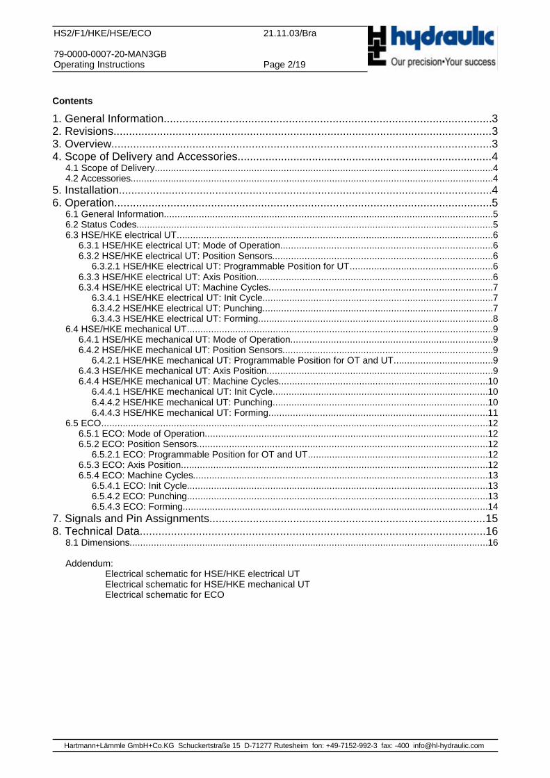
The device HS2/F1/HKE/HSE/ECO (called HS2 in this document) is used to control H+L punching systemslike HSE, HKE and ECO. All specific processes of the hydraulics are defined in the firmware of HS2. Thus,the user control (CNC / PLC) does not need to implement these processes. The benefits of this approachare:
o The user saves the effort (time / money) to implement the punching control flow.o The critical task of punching control is offloaded from the user CNC. HS2 is running at 0,2 ms / cycle !o The hydraulics is used in an optimum way - all optimisations are implemented in the HS2 firmware.o By using the boost outputs of HS2, valve switching is much faster than with standard PLC outputs
( approx. 7 ms compared to 17 ms).
Integration of the punching system into the user machine is very simple. The following diagram shows thesystem structure from the CNC / PLC view.
Hartmann+Lämmle GmbH+Co.KG Schuckertstraße 15 D-71277 Rutesheim fon: +49-7152-992-3 fax: -400 [email protected]
HS2/F1/HKE/HSE/ECO 21.11.03/Bra
79-0000-0007-20-MAN3GBOperating Instructions Page 4/19
4. Scope of Delivery and Accessories
4.1 Scope of Delivery
The scope of delivery contains: the device HS2/F1/HKE/HSE/ECOThe scope of delivery does not contain: external connectors, this manual.
4.2 Accessories
The device HS2 is to be mounted to a 35 mm DIN rail in the electronics cabinet. To connect the necessarysupply and I/Os, the following plugs are needed (not in the scope of delivery):
For X1: Type: MSTB2,5/8-ST-5,08 Phoenix No.: 17 57 07 7 1 pieceFor X2: Type: MSTB2,5/9-ST-5,08 Phoenix No.: 17 57 08 0 1 pieceFor X3: Type: MSTB2,5/10-ST-5,08 Phoenix No.: 17 57 09 3 1 pieceManuf.: Phoenix Contact, D-32825 Blomberg, fon: +49-5235-3-00, www.phoenixcontact.com
On request:: Item: Plug Set HS2/F1IdNo.: 79-0041-0008-00Contents:1 * MSTB2,5/8-ST-5,08 1 * MSTB2,5/9-ST-5,08 1 * MSTB2,5/10-ST-5,08
5. Installation
Setup all connections, as shown in the logic diagram (addendum). Meet the following requirements for thewire diameter:
Valves: up to 10 m: min 0,5 mm²up to 20 m: min 0,75 mm²
Position-Sensor: min 0,25 mm², shielded cable, connect shield with PE in electronics cabinetSupply: up to 1 m from DC supply: min 1 mm²
up to 2 m from DC supply: min 1,5 mm²Control lines: up to 2 m: min 0,25 mm²RS-232: up to 3 m: min 0,25 mm², shielded cable, connect shield with PE in electronics cabinet Ground (PE): max. 0,2 m to earth point, 1 mm²
Please note: all I/O for HS2 is DC coupled. Take care to have a low impedance connection on the 0V rail forthe HS2 as well as for your CNC/PLC. This is also important for the RS-232 interface. If you expierienceconnection problems, you might need an additional RS-232 coupler with opto-isolation (very seldom).
Please note the specifications for the power supply in the technical data.
Note: using a DC power supply with „hard“ control characteristic (electronic current limiter) can result inerroneous voltage drops due to peak current limiting. Using a DC power supply with „soft“ controlcharacteristic is preferred.
Please also note: document no. 79-0039-0019-00 and chapter „Diagnosis“.
Hartmann+Lämmle GmbH+Co.KG Schuckertstraße 15 D-71277 Rutesheim fon: +49-7152-992-3 fax: -400 [email protected]
HS2/F1/HKE/HSE/ECO 21.11.03/Bra
79-0000-0007-20-MAN3GBOperating Instructions Page 5/19
6. Operation
6.1 General Information
The HS2 is activated with the signal RUN. With RUN=0 the device can be reset. All outputs and internaldata will be cleared. For normal operation, RUN must be high.
HS2 will autonomously control all processes like punching, forming etc. The status codes in chapter 5.2 arevalid for all different hydraulic systems.
Depending of the hydraulic version, the correct mode of Operation must be selected. This selection is madeon rotary switch SW1. This switch has 16 positions named „1“ .. „F“ .See mechanical drawing in Chapter 8.1to identify switch SW1.
Mode 2: HSE/HKE with electrical UT controlMode 0: HSE/HKE with mechanical UT controlMode 3: ECO
The operation with HSE, ECO and HKE will be described in separate chapters. For oneversion of hydraulic, you need only to read one specific chapter.
For HSE/HKE with electrical UT control: --> chapter 6.3
For HSE/HKE with mechanical UT control: --> chapter 6.4
For ECO: --> chapter 6.5
6.2 Status Codes
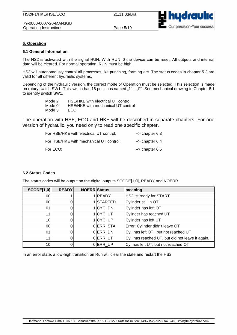
The status codes will be output on the digital outputs SCODE[1,0], READY and NOERR.
SCODE[1,0] READY NOERR Status meaning
00 1 1 READY HS2 ist ready for START00 0 1 STARTED Cylinder still in OT01 0 1 CYC_DN Cylinder has left OT11 0 1 CYC_UT Cylinder has reached UT10 0 1 CYC_UP Cylinder has left UT00 0 0 ERR_STA Error: Cylinder didn't leave OT01 0 0 ERR_DN Cyl. has left OT , but not reached UT11 0 0 ERR_UT Cyl. has reached UT, but did not leave it again.
10 0 0 ERR_UP Cy. has left UT, but not reached OT
In an error state, a low-high transition on Run will clear the state and restart the HS2.
Hartmann+Lämmle GmbH+Co.KG Schuckertstraße 15 D-71277 Rutesheim fon: +49-7152-992-3 fax: -400 [email protected]
1. UT Position
2. UT Position
OT proxy not shown.(Mounted either onmain valve or directlyto monitor ram)
UT Selection Relay
HS2/X2: 8
Ram
HS2/F1/HKE/HSE/ECO 21.11.03/Bra
79-0000-0007-20-MAN3GBOperating Instructions Page 6/19
6.3 HSE/HKE electrical UT
6.3.1 HSE/HKE electrical UT: Mode of Operation
The rotary switch must be set to position „2“.
OT (upper deadpoint) is controlled mechanically through the copy valve.UT (lower deadpoint) is controlled electrically through a proxy switch monitoring tha ram.
6.3.2 HSE/HKE electrical UT: Position Sensors
HSE uses two proxy switches: one for OT (upper dead point) and an other one for UT (lower dead point).
The UT proxy must alway be mounted externally. In case of a HSE with a main valve size 10, the OT proxyis mountet on the main valve. For other main valve sizes (6 and 25), the OT proxy must also be mountedexternally to direclty monitor the ram position.
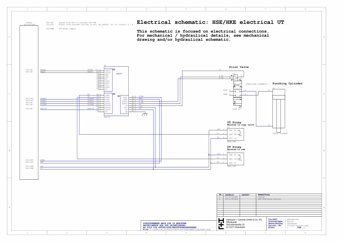
OT and UT proxies must be connected to the HS2 according to the electrical schematic.
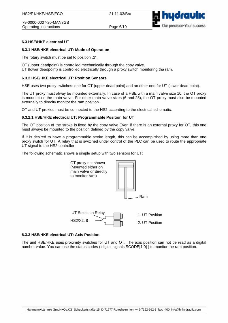
6.3.2.1 HSE/HKE electrical UT: Programmable Position for UT
The OT position of the stroke is fixed by the copy valve.Even if there is an external proxy for OT, this onemust always be mounted to the position defined by the copy valve.
If it is desired to have a programmable stroke length, this can be accomplished by using more than oneproxy switch for UT. A relay that is switched under control of the PLC can be used to route the appropriateUT signal to the HS2 controller.
The following schematic shows a simple setup with two sensors for UT:
6.3.3 HSE/HKE electrical UT: Axis Position
The unit HSE/HKE uses proximity switches for UT and OT. The axis position can not be read as a digitalnumber value. You can use the status codes ( digital signals SCODE[1,0] ) to monitor the ram position.
Hartmann+Lämmle GmbH+Co.KG Schuckertstraße 15 D-71277 Rutesheim fon: +49-7152-992-3 fax: -400 [email protected]
OT-Signal
UT-Signal
START1
READY
RAM-POS
1
2
5
00 01 11 1000 00SCODE[1,0]
RAM -UT
4
36
F-DN
F-UP
HS2/F1/HKE/HSE/ECO 21.11.03/Bra
79-0000-0007-20-MAN3GBOperating Instructions Page 7/19
6.3.4 HSE/HKE electrical UT: Machine Cycles
The following gives the description of different machine cycles. After power-up or an error condition, an initcycle must be conducted. After that, working cycles like punching or forming can be started.
6.3.4.1 HSE/HKE electrical UT: Init Cycle
After power-up or in case of an error, the init cycle must be started. After power-on, give RUN (0-1).
The system will now be ready to start a cycle. To enable the starting via START1 or START2, the signalSTEN (STart Enable) must be high. When the gating function of STEN is not needed, it can be hard wiredto 24V.
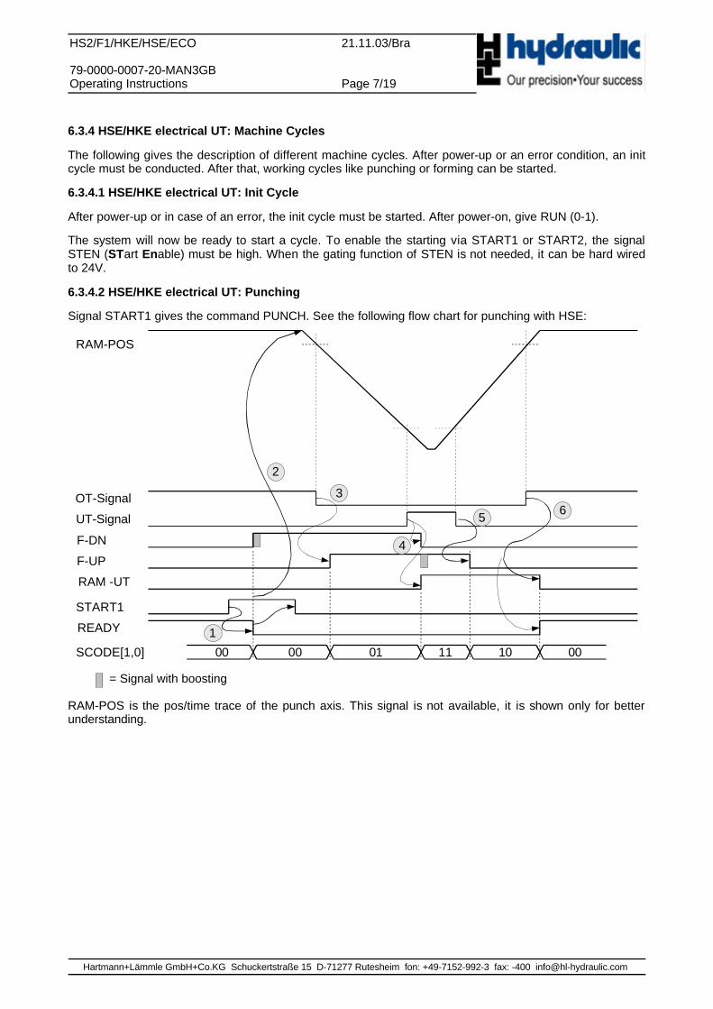
6.3.4.2 HSE/HKE electrical UT: Punching
Signal START1 gives the command PUNCH. See the following flow chart for punching with HSE:
= Signal with boosting
RAM-POS is the pos/time trace of the punch axis. This signal is not available, it is shown only for betterunderstanding.
Hartmann+Lämmle GmbH+Co.KG Schuckertstraße 15 D-71277 Rutesheim fon: +49-7152-992-3 fax: -400 [email protected]
OT-Signal
START2
READY
RAM-POS
1
2
5
00 01 1000 00SCODE[1,0]
4
3F-DN
F-UP
RAM -UT
HS2/F1/HKE/HSE/ECO 21.11.03/Bra
79-0000-0007-20-MAN3GBOperating Instructions Page 8/19
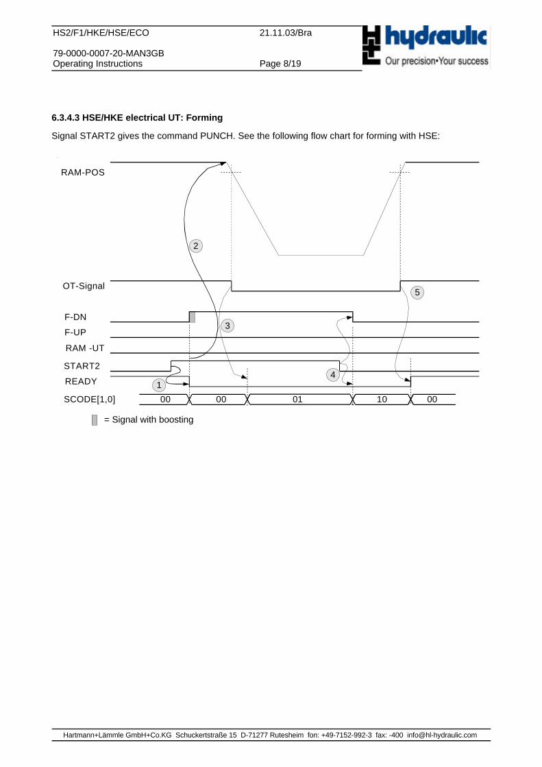
6.3.4.3 HSE/HKE electrical UT: Forming
Signal START2 gives the command PUNCH. See the following flow chart for forming with HSE:
= Signal with boosting
Hartmann+Lämmle GmbH+Co.KG Schuckertstraße 15 D-71277 Rutesheim fon: +49-7152-992-3 fax: -400 [email protected]

HS2/F1/HKE/HSE/ECO 21.11.03/Bra
79-0000-0007-20-MAN3GBOperating Instructions Page 9/19
6.4 HSE/HKE mechanical UT
6.4.1 HSE/HKE mechanical UT: Mode of Operation
The rotary switch must be set to position „0“.
OT (upper deadpoint) is controlled mechanically through the copy valve.UT (lower deadpoint) is controlled mechanically through the copy valve.
6.4.2 HSE/HKE mechanical UT: Position Sensors
HKE uses two proxy switches: one for OT (upper dead point) and an other one for UT (lower dead point).
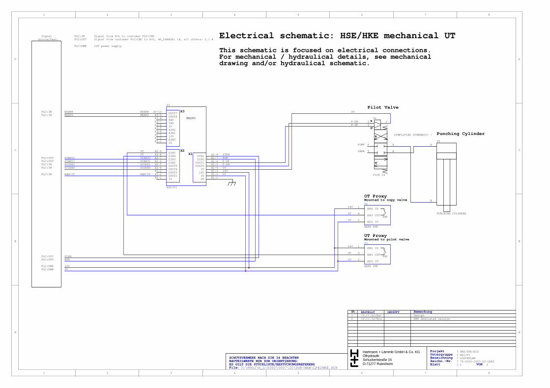
Both proxies are mounted to the HKL unit. OT proxy is mounted on the copy valve, UT proxy is mounted onthe piloting valve size 04.
OT and UT proxies must be connected to the HS2 according to the electrical schematic.
6.4.2.1 HSE/HKE mechanical UT: Programmable Position for OT and UT
The upper stop position (OT) and lower stop position (UT) are defined by the setup of the mechanicalfeedback system. Since the stroke length is defined by the difference between OT and UT, it will also bepredefined by the mechanical setup.
If OT and UT need to be programmable under PLC control, there is a solution for electro-pneumaticadjustment of the mechanical setup. The thwo proxy switches fo OT and UT will remain unchanged for thissolution.
6.4.3 HSE/HKE mechanical UT: Axis Position
The unit HKE use proximity switches for UT and OT. The axis position can not be read as a digital numbervalue. You can use the status codes ( digital signals SCODE[1,0] ) to monitor the ram position.
Hartmann+Lämmle GmbH+Co.KG Schuckertstraße 15 D-71277 Rutesheim fon: +49-7152-992-3 fax: -400 [email protected]
OT-Signal
UT-Signal
F-DN
F-UP
START1
READY
RAM-POS
1
2
3
4
5
00 01 11 1000 00SCODE[1,0]
RAM-UT
TH
TH = 5ms
6
HS2/F1/HKE/HSE/ECO 21.11.03/Bra
79-0000-0007-20-MAN3GBOperating Instructions Page 10/19
6.4.4 HSE/HKE mechanical UT: Machine Cycles
The following gives the description of different machine cycles. After power-up or an error condition, an initcycle must be conducted. After that, working cycles like punching or forming can be started.
6.4.4.1 HSE/HKE mechanical UT: Init Cycle
After power-up or in case of an error, the init cycle must be started. After power-on, give RUN (0-1).
The ram will be commanded into the top position (OT), until the OT proxy switch gives a signal. If the signalOT gives a 1 level, the HS2 will output the READY=1 signal.
The system will now be ready to start a cycle. To enable the starting via START1 or START2, the signalSTEN (STart Enable) must be high. When the gating function of STEN is not needed, it can be hard wiredto 24V.
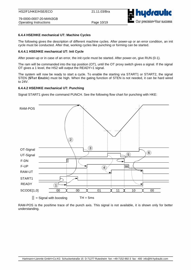
6.4.4.2 HSE/HKE mechanical UT: Punching
Signal START1 gives the command PUNCH. See the following flow chart for punching with HKE:
= Signal with boosting
RAM-POS is the pos/time trace of the punch axis. This signal is not available, it is shown only for betterunderstanding.
Hartmann+Lämmle GmbH+Co.KG Schuckertstraße 15 D-71277 Rutesheim fon: +49-7152-992-3 fax: -400 [email protected]
OT-Signal
START2
READY
RAM-POS
1
2
5
00 01 1000 00SCODE[1,0]
4
3F-DN
F-UP
RAM -UT
HS2/F1/HKE/HSE/ECO 21.11.03/Bra
79-0000-0007-20-MAN3GBOperating Instructions Page 11/19
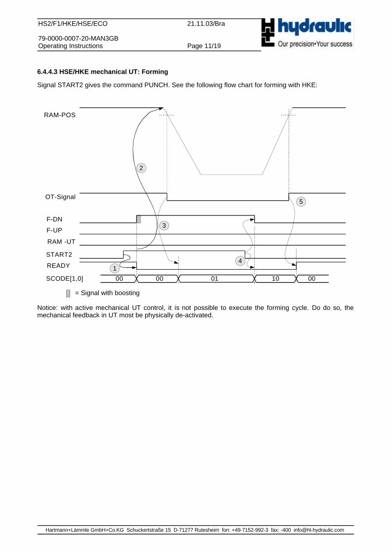
6.4.4.3 HSE/HKE mechanical UT: Forming
Signal START2 gives the command PUNCH. See the following flow chart for forming with HKE:
= Signal with boosting
Notice: with active mechanical UT control, it is not possible to execute the forming cycle. Do do so, themechanical feedback in UT most be physically de-activated.
Hartmann+Lämmle GmbH+Co.KG Schuckertstraße 15 D-71277 Rutesheim fon: +49-7152-992-3 fax: -400 [email protected]
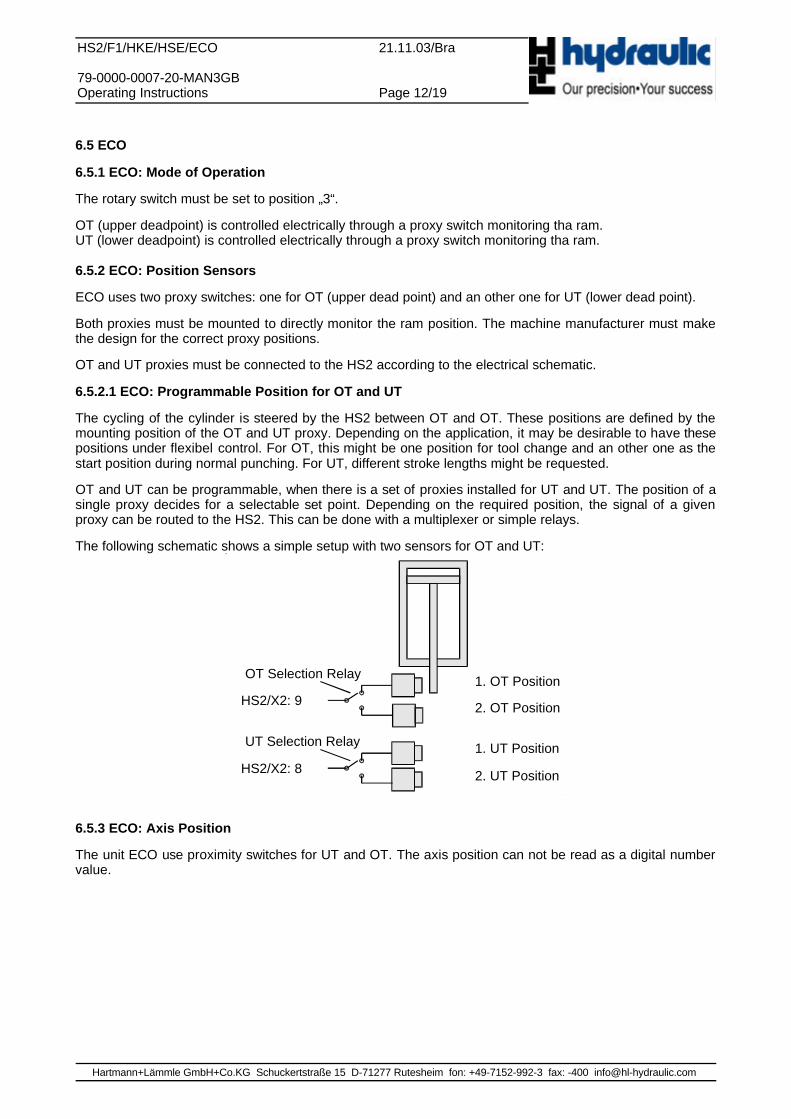
1. OT Position
2. OT Position
1. UT Position
2. UT Position
OT Selection Relay
UT Selection Relay
HS2/X2: 9
HS2/X2: 8
HS2/F1/HKE/HSE/ECO 21.11.03/Bra
79-0000-0007-20-MAN3GBOperating Instructions Page 12/19
6.5 ECO
6.5.1 ECO: Mode of Operation
The rotary switch must be set to position „3“.
OT (upper deadpoint) is controlled electrically through a proxy switch monitoring tha ram.UT (lower deadpoint) is controlled electrically through a proxy switch monitoring tha ram.
6.5.2 ECO: Position Sensors
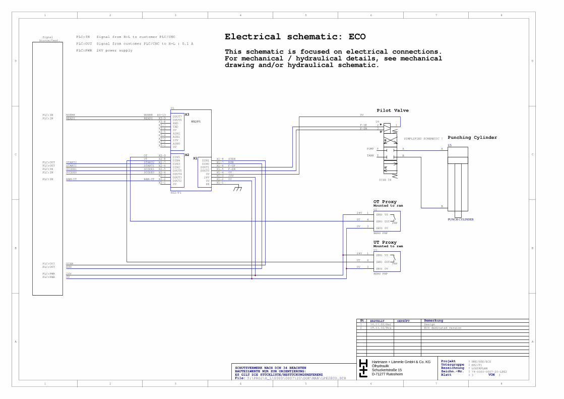
ECO uses two proxy switches: one for OT (upper dead point) and an other one for UT (lower dead point).
Both proxies must be mounted to directly monitor the ram position. The machine manufacturer must makethe design for the correct proxy positions.
OT and UT proxies must be connected to the HS2 according to the electrical schematic.
6.5.2.1 ECO: Programmable Position for OT and UT
The cycling of the cylinder is steered by the HS2 between OT and OT. These positions are defined by themounting position of the OT and UT proxy. Depending on the application, it may be desirable to have thesepositions under flexibel control. For OT, this might be one position for tool change and an other one as thestart position during normal punching. For UT, different stroke lengths might be requested.
OT and UT can be programmable, when there is a set of proxies installed for UT and UT. The position of asingle proxy decides for a selectable set point. Depending on the required position, the signal of a givenproxy can be routed to the HS2. This can be done with a multiplexer or simple relays.
The following schematic shows a simple setup with two sensors for OT and UT:
6.5.3 ECO: Axis Position
The unit ECO use proximity switches for UT and OT. The axis position can not be read as a digital numbervalue.
Hartmann+Lämmle GmbH+Co.KG Schuckertstraße 15 D-71277 Rutesheim fon: +49-7152-992-3 fax: -400 [email protected]
OT-Signal
UT-Signal
START1
READY
RAM-POS
1
2
5
00 01 11 1000 00SCODE[1,0]
RAM -UT
4
3 6
F-DN
F-UP
HS2/F1/HKE/HSE/ECO 21.11.03/Bra
79-0000-0007-20-MAN3GBOperating Instructions Page 13/19
6.5.4 ECO: Machine Cycles
The following gives the description of different machine cycles. After power-up or an error condition, an initcycle must be conducted. After that, working cycles like punching or forming can be started.
6.5.4.1 ECO: Init Cycle
After power-up or in case of an error, the init cycle must be started. After power-on, give RUN (0-1).
The ram will be commanded into the top position (OT), until the OT proxy switch gives a signal. If the signalOT gives a 1 level, the HS2 will output the READY=1 signal.
The system will now be ready to start a cycle. To enable the starting via START1 or START2, the signalSTEN (STart Enable) must be high. When the gating function of STEN is not needed, it can be hard wiredto 24V.
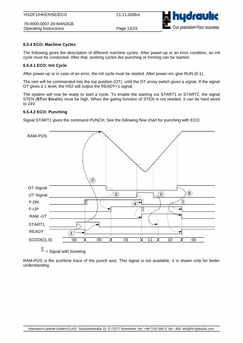
6.5.4.2 ECO: Punching
Signal START1 gives the command PUNCH. See the following flow chart for punching with ECO:
= Signal with boosting
RAM-POS is the pos/time trace of the punch axis. This signal is not available, it is shown only for betterunderstanding.
Hartmann+Lämmle GmbH+Co.KG Schuckertstraße 15 D-71277 Rutesheim fon: +49-7152-992-3 fax: -400 [email protected]
OT-Signal
START2
READY
RAM-POS
1
2
5
00 01 1000 00SCODE[1,0]
RAM -UT
4
3F-DN
F-UP
HS2/F1/HKE/HSE/ECO 21.11.03/Bra
79-0000-0007-20-MAN3GBOperating Instructions Page 14/19
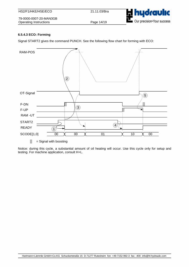
6.5.4.3 ECO: Forming
Signal START2 gives the command PUNCH. See the following flow chart for forming with ECO:
= Signal with boosting
Notice: during this cycle, a substantial amount of oil heating will occur. Use this cycle only for setup andtesting. For machine application, consult H+L.
Hartmann+Lämmle GmbH+Co.KG Schuckertstraße 15 D-71277 Rutesheim fon: +49-7152-992-3 fax: -400 [email protected]
HS2/F1/HKE/HSE/ECO 21.11.03/Bra
79-0000-0007-20-MAN3GBOperating Instructions Page 15/19
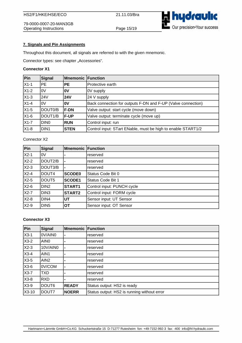
7. Signals and Pin Assignments
Throughout this document, all signals are referred to with the given mnemonic.
Connector types: see chapter „Accessories“.
Connector X1
Pin Signal Mnemonic Function
X1-1 PE PE Protective earth
X1-2 0V 0V 0V supply
X1-3 24V 24V 24 V supply
X1-4 0V 0V Back connection for outputs F-DN and F-UP (Valve connection)
X1-5 DOUT0/B F-DN Valve output: start cycle (move down)
X1-6 DOUT1/B F-UP Valve output: terminate cycle (move up)
X1-7 DIN0 RUN Control input: run
X1-8 DIN1 STEN Control input: STart ENable, must be high to enable START1/2
Connector X2
Pin Signal Mnemonic Function
X2-1 0V - reserved
X2-2 DOUT2/B - reserved
X2-3 DOUT3/B - reserved
X2-4 DOUT4 SCODE0 Status Code Bit 0
X2-5 DOUT5 SCODE1 Status Code Bit 1
X2-6 DIN2 START1 Control input: PUNCH cycle
X2-7 DIN3 START2 Control input: FORM cycle
X2-8 DIN4 UT Sensor input: UT Sensor
X2-9 DIN5 OT Sensor input: OT Sensor
Connector X3
Pin Signal Mnemonic Function
X3-1 0V/AIN0 - reserved
X3-2 AIN0 - reserved
X2-3 10V/AIN0 - reserved
X3-4 AIN1 - reserved
X3-5 AIN2 - reserved
X3-6 0V/COM - reserved
X3-7 TXD - reserved
X3-8 RXD - reserved
X3-9 DOUT6 READY Status output: HS2 is ready
X3-10 DOUT7 NOERR Status output: HS2 is running without error
Hartmann+Lämmle GmbH+Co.KG Schuckertstraße 15 D-71277 Rutesheim fon: +49-7152-992-3 fax: -400 [email protected]
X1
1 1
X2
2 3 4 5 6 7 8 2 3 4 5 6 7 8 9
112,0 60,0
96,0
X1X2
X31
X3
345678910 2
SW1
HS2/F1/HKE/HSE/ECO 21.11.03/Bra
79-0000-0007-20-MAN3GBOperating Instructions Page 16/19
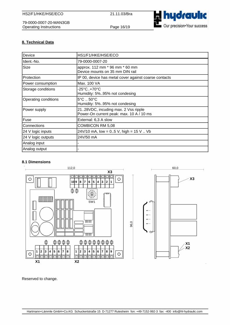
8. Technical Data
Device HS1/F1/HKE/HSE/ECO
Ident.-No. 79-0000-0007-20Size approx. 112 mm * 96 mm * 60 mm
Device mounts on 35 mm DIN railProtection IP 00, device has metal cover against coarse contactsPower consumption Max. 100 VAStorage conditions -25°C..+70°C
Humidity: 5%..95% not condesingOperating conditions 5°C .. 50°C
Humidity: 5%..95% not condesingPower supply 21..28VDC, incuding max. 2 Vss ripple
Power-On current peak: max. 10 A / 10 msFuse External: 6,3 A slowConnections COMBICON RM 5,0824 V logic inputs 24V/10 mA, low = 0..5 V, high = 15 V .. Vb24 V logic outputs 24V/50 mAAnalog input -Analog output -
8.1 Dimensions
Reserved to change.
Hartmann+Lämmle GmbH+Co.KG Schuckertstraße 15 D-71277 Rutesheim fon: +49-7152-992-3 fax: -400 [email protected]
1 2 3 4 5 6 7 8
A
B
C
D
87654321
D
C
B
A
Hartmann + Lämmle GmbH & Co. KGÖlhydraulikSchuckertstraße 15D-71277 Rutesheim
ProjektUntergruppeBezeichnungZeichn.-Nr.Blatt
File: T:\PROJ\H_L\0000\0007\20\DOK\MAN\LPE2HSE.SCHVON
:
St. Bemerkung
::
::
ERSTELLT GEPRÜFT1
SCHUTZVERMERK NACH DIN 34 BEACHTENBAUTEILWERTE NUR ZUR ORIENTIERUNG:ES GILT DIE STÜCKLISTE/BESTÜCKUNGSREFERENZ
PE X1-10V X1-224V X1-30V X1-4DOUT0 X1-5DOUT1 X1-6DIN0 X1-7DIN1 X1-8
0VX2-1 DOUT2X2-2 DOUT3X2-3 DOUT4X2-4 DOUT5X2-5 DIN2X2-6 DIN3X2-7 DIN4X2-8 DIN5X2-9
0VX3-1 AIN0X3-2 10VX3-3 AIN1X3-4 AIN2X3-5 0VX3-6 TXDX3-7 RXDX3-8 DOUT6X3-9 DOUT7X3-10
X1X2
X3
HS2/F1
U1
HS2/F1
F-DNF-UPRUNSTEN
F-DNF-UP
0V
0V
START1START2
START1START2
RUNSTEN
READYNOERR
HS2/F1HKE/HSE/ECO
LOGIKPLAN79-0000-0007-20-LPE21 3
14.11.02/Hai Design
0V24V
PLC:INPLC:IN
PLC:OUTPLC:OUT
PLC:OUTPLC:OUT
PLC:PWRPLC:PWR
SignalSource/Dest.
PLC:IN Signal from H+L to customer PLC/CNCSignal from customer PLC/CNC to H+L, HD_CHARGE: 1A, all others: 0,1 APLC:OUT
24V power supplyPLC:PWR
RAM-UT
PLC:IN
RAM-UT
SCODE1SCODE0 SCODE0
SCODE1
NOERRREADY
0V24V
PLC:IN
PLC:IN
(BN) VS1
(BU) 0V3
(BK) OUT4PNP
U2
BERO PNP
(BN) VS1
(BU) 0V3
(BK) OUT4PNP
U3
BERO PNP
OT
UT
24V
0V
24V
0V
UTOT
Punching Cylinder
P
T
A
B
2 13
ab
ba
U4
SIZE 04
A
B
U5
PUNCH CYLINDER
Pilot Valve
OT ProxyMounted to copy valve
UT ProxyMounted to ram
Electrical schematic: HSE/HKE electrical UTThis schematic is focused on electrical connections.For mechanical / hydraulical details, see mechanicaldrawing and/or hydraulical schematic.
19.11.02/Bra HSE dedicated version2
SIMPLIFIED SCHEMATIC !
PUMP
TANK
1 2 3 4 5 6 7 8
A
B
C
D
87654321
D
C
B
A
Hartmann + Lämmle GmbH & Co. KGÖlhydraulikSchuckertstraße 15D-71277 Rutesheim
ProjektUntergruppeBezeichnungZeichn.-Nr.Blatt
File: T:\PROJ\H_L\0000\0007\20\DOK\MAN\LPE2HKE.SCHVON
:
St. Bemerkung
::
::
ERSTELLT GEPRÜFT1
SCHUTZVERMERK NACH DIN 34 BEACHTENBAUTEILWERTE NUR ZUR ORIENTIERUNG:ES GILT DIE STÜCKLISTE/BESTÜCKUNGSREFERENZ
PE X1-10V X1-224V X1-30V X1-4DOUT0 X1-5DOUT1 X1-6DIN0 X1-7DIN1 X1-8
0VX2-1 DOUT2X2-2 DOUT3X2-3 DOUT4X2-4 DOUT5X2-5 DIN2X2-6 DIN3X2-7 DIN4X2-8 DIN5X2-9
0VX3-1 AIN0X3-2 10VX3-3 AIN1X3-4 AIN2X3-5 0VX3-6 TXDX3-7 RXDX3-8 DOUT6X3-9 DOUT7X3-10
X1X2
X3
HS2/F1
U1
HS2/F1
F-DNF-UPRUNSTEN
F-DNF-UP
0V
0V
START1START2
START1START2
RUNSTEN
READYNOERR
HS2/F1HKE/HSE/ECO
LOGIKPLAN79-0000-0007-20-LPE22 3
14.11.02/Hai Design
0V24V
PLC:INPLC:IN
PLC:OUTPLC:OUT
PLC:OUTPLC:OUT
PLC:PWRPLC:PWR
SignalSource/Dest.
PLC:IN Signal from H+L to customer PLC/CNCSignal from customer PLC/CNC to H+L, HD_CHARGE: 1A, all others: 0,1 APLC:OUT
24V power supplyPLC:PWR
RAM-UT
PLC:IN
RAM-UT
SCODE1SCODE0 SCODE0
SCODE1
NOERRREADY
0V24V
PLC:IN
PLC:IN
(BN) VS1
(BU) 0V3
(BK) OUT4PNP
U2
BERO PNP
(BN) VS1
(BU) 0V3
(BK) OUT4PNP
U3
BERO PNP
OT
UT
24V
0V
24V
0V
UTOT
Punching Cylinder
P
T
A
B
2 13
ab
ba
U4
SIZE 04
A
B
U5
PUNCHING CYLINDER
Pilot Valve
OT ProxyMounted to copy valve
UT ProxyMounted to pilot valve
Electrical schematic: HSE/HKE mechanical UTThis schematic is focused on electrical connections.For mechanical / hydraulical details, see mechanicaldrawing and/or hydraulical schematic.
19.11.02/Bra HKE dedicated version2
SIMPLIFIED SCHEMATIC !
PUMP
TANK
1 2 3 4 5 6 7 8
A
B
C
D
87654321
D
C
B
A
Hartmann + Lämmle GmbH & Co. KGÖlhydraulikSchuckertstraße 15D-71277 Rutesheim
ProjektUntergruppeBezeichnungZeichn.-Nr.Blatt
File: T:\PROJ\H_L\0000\0007\20\DOK\MAN\LPE2ECO.SCHVON
:
St. Bemerkung
::
::
ERSTELLT GEPRÜFT1
SCHUTZVERMERK NACH DIN 34 BEACHTENBAUTEILWERTE NUR ZUR ORIENTIERUNG:ES GILT DIE STÜCKLISTE/BESTÜCKUNGSREFERENZ
PE X1-10V X1-224V X1-30V X1-4DOUT0 X1-5DOUT1 X1-6DIN0 X1-7DIN1 X1-8
0VX2-1 DOUT2X2-2 DOUT3X2-3 DOUT4X2-4 DOUT5X2-5 DIN2X2-6 DIN3X2-7 DIN4X2-8 DIN5X2-9
0VX3-1 AIN0X3-2 10VX3-3 AIN1X3-4 AIN2X3-5 0VX3-6 TXDX3-7 RXDX3-8 DOUT6X3-9 DOUT7X3-10
X1X2
X3
HS2/F1
U1
HS2/F1
F-DNF-UPRUNSTEN
F-DNF-UP
0V
0V
START1START2
START1START2
RUNSTEN
READYNOERR
HS2/F1HKE/HSE/ECO
LOGIKPLAN79-0000-0007-20-LPE23 3
14.11.02/Hai Design
0V24V
PLC:INPLC:IN
PLC:OUTPLC:OUT
PLC:OUTPLC:OUT
PLC:PWRPLC:PWR
SignalSource/Dest.
PLC:IN Signal from H+L to customer PLC/CNC
Signal from customer PLC/CNC to H+L : 0,1 APLC:OUT
24V power supplyPLC:PWR
RAM-UT
PLC:IN
RAM-UT
SCODE1SCODE0 SCODE0
SCODE1
NOERRREADY
0V24V
PLC:IN
PLC:IN
(BN) VS1
(BU) 0V3
(BK) OUT4PNP
U2
BERO PNP
(BN) VS1
(BU) 0V3
(BK) OUT4PNP
U3
BERO PNP
OT
UT
24V
0V
24V
0V
UTOT
Punching Cylinder
P
T
A
B
2 13
ab
ba
U4
SIZE 04
A
B
U5
PUNCH CYLINDER
Pilot Valve
OT ProxyMounted to ram
UT ProxyMounted to ram
Electrical schematic: ECOThis schematic is focused on electrical connections.For mechanical / hydraulical details, see mechanicaldrawing and/or hydraulical schematic.
19.11.02/Bra ECO dedicated version2
SIMPLIFIED SCHEMATIC !
PUMP
TANK


![Diccionario Tecnico Ingles - Español HKE[1]](https://img.pdfslide.net/doc/110x75/55cf99fb550346d0339ffca6/diccionario-tecnico-ingles-espanol-hke1.jpg)