Embed Size (px)
Citation preview
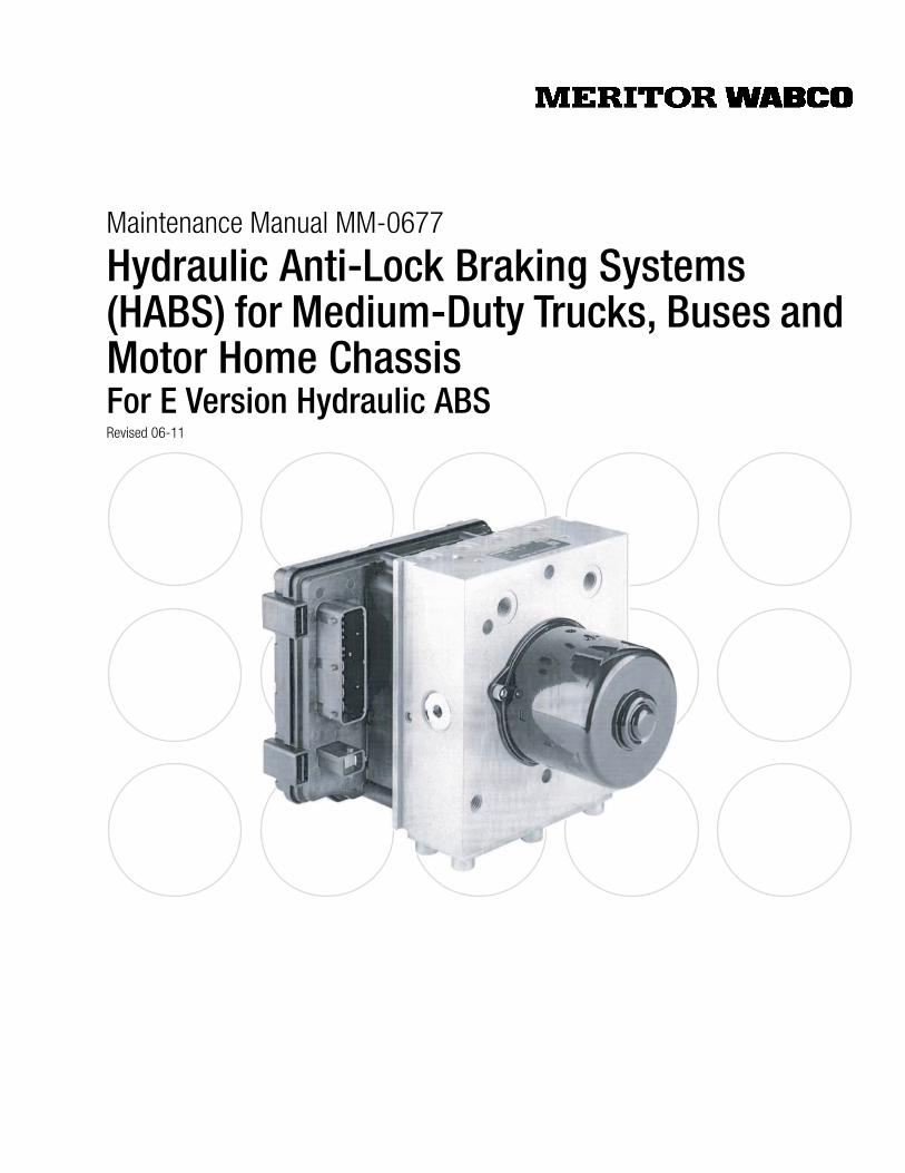
Maintenance Manual MM-0677
Hydraulic Anti-Lock Braking Systems (HABS) for Medium-Duty Trucks, Buses and Motor Home ChassisFor E Version Hydraulic ABSRevised 06-11
Service Notes
Information contained in this publication was in effect at the time the publication was approved for printing and is subject to change without notice or liability. Meritor WABCO reserves the right to revise the information presented or to discontinue the production of parts described at any time.
Meritor WABCO Maintenance Manual MM-0677 (Revised 06-11)
About This ManualThis manual provides instructions for Meritor WABCO’s E Version hydraulic anti-lock braking system (HABS) for medium-duty trucks, buses and motor home chassis.
Before You Begin1. Read and understand all instructions and procedures before
you begin to service components.
2. Read and observe all Warning and Caution hazard alert messages in this publication. They provide information that can help prevent serious personal injury, damage to components, or both.
3. Follow your company’s maintenance and service, installation, and diagnostics guidelines.
4. Use special tools when required to help avoid serious personal injury and damage to components.
Hazard Alert Messages and Torque Symbols
WARNINGA Warning alerts you to an instruction or procedure that you must follow exactly to avoid serious personal injury and damage to components.
CAUTIONA Caution alerts you to an instruction or procedure that you must follow exactly to avoid damage to components.
@ This symbol alerts you to tighten fasteners to a specified torque value.
How to Obtain Additional Maintenance and Service Information
On the WebVisit Literature on Demand at meritor.com to access and order product, service, aftermarket, and warranty literature for Meritor’s truck, trailer and specialty vehicle components. Meritor WABCO publications are also available on our website:
meritorwabco.com
Literature on Demand DVD (LODonDVD)The LODonDVD contains product, service and warranty information for Meritor and Meritor WABCO products. To order the DVD, visit Literature on Demand at meritor.com and specify TP-0742.
How to Obtain Tools and Supplies Specified in This ManualCall Meritor’s Commercial Vehicle Aftermarket at 888-725-9355 to obtain Meritor tools and supplies.
Contents
pg. i Asbestos and Non-Asbestos Fibers1 Section 1: Introduction
MaintenanceManual InformationOverviewHow Hydraulic ABS Works
2 System LayoutSystem ComponentsElectronic Control Unit (ECU)
3 Modulator AssemblySensors
4 ABS Warning LampTOOLBOX™ Software
5 Section 2: Troubleshooting and TestingMaintenanceGeneral InformationWiring DiagramsSystem Wiring Information
6 System DiagnosticsMeritor WABCO TOOLBOX™ Software
8 Blink Code Diagnostics9 Using Blink Code Diagnostics — Optional Feature20 Testing the System
Meritor WABCO TOOLBOX™ SoftwareE Version Hydraulic ABS Menus and Toolbars
25 Standard TestingSystem Requirements and Component TestsStandard Component Testing
27 Section 3: Component ReplacementComponent Removal and InstallationSensorsWheel Speed Sensor Replacement — Front AxleWheel Speed Sensor Replacement — Rear Axle
28 Electronic Control Unit (ECU)29 Modulator Assembly30 Brake Bleeding Procedures
Pressure Fill and Bleed
Asbestos and Non-Asbestos Fibers
iMeritor WABCO Maintenance Manual MM-0677 (Revised 06-11)
ASBESTOS FIBERS WARNING The following procedures for servicing brakes are recommended to reduce exposure toasbestos ber dust, a cancer and lung disease hazard. Material Safety Data Sheets areavailable from ArvinMeritor.
Hazard SummaryBecause some brake linings contain asbestos, workers who service brakes must understand the potential hazards of asbestos and precautions for reducing risks. Exposure to airborne asbestos dust can cause serious and possibly fatal diseases, including asbestosis (a chronic lung disease) and cancer, principally lung cancer and mesothelioma (a cancer of the lining of the chest or abdominal cavities). Some studies show that the risk of lung cancer among persons who smoke and who are exposed to asbestos is much greater than the risk for non-smokers. Symptoms of these diseases may not become apparent for 15, 20 or more years after the rst exposure to asbestos.
Accordingly, workers must use caution to avoid creating and breathing dust when servicing brakes. Speci c recommended work practices for reducing exposure to asbestos dust follow . Consult your employer for more details.
Recommended Work Practices1. Separate Work Areas. Whenever feasible, service brakes in a separate area away from other operations to reduce risks to unprotected persons. OSHA has set a maximum allowable level of exposure for asbestos of 0.1 f/cc as an 8-hour time-weighted average and 1.0 f/cc averaged over a 30-minute period. Scientists disagree, however, to what extent adherence to the maximum allowable exposure levels will eliminate the risk of disease that can result from inhaling asbestos dust. OSHA requires that the following sign be posted at the entrance to areas where exposures exceed either of the maximum allowable levels:
DANGER: ASBESTOSCANCER AND LUNG DISEASE HAZARD
AUTHORIZED PERSONNEL ONLYRESPIRATORS AND PROTECTIVE CLOTHING
ARE REQUIRED IN THIS AREA.
2. Respiratory Protection. Wear a respirator equipped with a high-ef ciency (HEP A) lter approved by NIOSH or MSHA for use with asbestos at all times when servicing brakes, beginning with the removal of the wheels.
3. Procedures for Servicing Brakes.
a. Enclose the brake assembly within a negative pressure enclosure. The enclosure should be equipped with a HEPA vacuum and worker arm sleeves. With the enclosure in place, use the HEPA vacuum to loosen and vacuum residue from the brake parts.
b. As an alternative procedure, use a catch basin with water and a biodegradable, non-phosphate, water-based detergent to wash the brake drum or rotor and other brake parts. The solution should be applied with low pressure to prevent dust from becoming airborne. Allow the solution to ow between the brake drum and the brake support or the brake rotor and caliper. The wheel hub and brake assembly components should be thoroughly wetted to suppress dust before the brake shoes or brake pads are removed. Wipe the brake parts clean with a cloth.
c. If an enclosed vacuum system or brake washing equipment is not available, employers may adopt their own written procedures for servicing brakes, provided that the exposure levels associated with the employer’s procedures do not exceed the levels associated with the enclosed vacuum system or brake washing equipment. Consult OSHA regulations for more details.
d. Wear a respirator equipped with a HEPA lter approved by NIOSH or MSHA for use with asbestos when grinding or machining brake linings. In addition, do such work in an area with a local exhaust ventilation system equipped with a HEPA lter .
e. NEVER use compressed air by itself, dry brushing, or a vacuum not equipped with a HEPA lter when cleaning brake parts or assemblies. NEVER use carcinogenic solvents, ammable solvents, or solvents that can damage brake components as wetting agents.
4. Cleaning Work Areas. Clean work areas with a vacuum equipped with a HEPA lter or by wet wiping. NEVER use compressed air or dry sweeping to clean work areas. When you empty vacuum cleaners and handle used rags, wear a respirator equipped with a HEPA lter approved by NIOSH or MSHA for use with asbestos. When you replace a HEPA lter , wet the lter with a ne mist of water and dispose of the used lter with care.
5. Worker Clean-Up. After servicing brakes, wash your hands before you eat, drink or smoke. Shower after work. Do not wear work clothes home. Use a vacuum equipped with a HEPA lter to vacuum work clothes after they are worn. Launder them separately. Do not shake or use compressed air to remove dust from work clothes.
6. Waste Disposal. Dispose of discarded linings, used rags, cloths and HEPA lters with care, such as in sealed plastic bags. Consult applicable EPA, state and local regulations on waste disposal.
Regulatory GuidanceReferences to OSHA, NIOSH, MSHA, and EPA, which are regulatory agencies in the United States, are made to provide further guidance to employers and workers employed within the United States. Employers and workers employed outside of the United States should consult the regulations that apply to them for further guidance.
NON-ASBESTOS FIBERS WARNING The following procedures for servicing brakes are recommended to reduce exposure tonon-asbestos ber dust, a cancer and lung disease hazard. Material Safety DataSheets are available from ArvinMeritor.
Hazard SummaryMost recently manufactured brake linings do not contain asbestos bers. These brake linings may contain one or more of a variety of ingredients, including glass bers, mineral wool, aramid bers, ceramic bers and silica that can present health risks if inhaled. Scientists disagree on the extent of the risks from exposure to these substances. Nonetheless, exposure to silica dust can cause silicosis, a non-cancerous lung disease. Silicosis gradually reduces lung capacity and ef ciency and can result in serious breathing dif culty . Some scientists believe other types of non-asbestos bers, when inhaled, can cause similar diseases of the lung. In addition, silica dust and ceramic ber dust are known to the State of California to cause lung cancer . U.S. and international agencies have also determined that dust from mineral wool, ceramic bers and silica are potential causes of cancer.
Accordingly, workers must use caution to avoid creating and breathing dust when servicing brakes. Speci c recommended work practices for reducing exposure to non-asbestos dust follow. Consult your employer for more details.
Recommended Work Practices1. Separate Work Areas. Whenever feasible, service brakes in a separate area away from other operations to reduce risks to unprotected persons.
2. Respiratory Protection. OSHA has set a maximum allowable level of exposure for silica of 0.1 mg/m3 as an 8-hour time-weighted average. Some manufacturers of non-asbestos brake linings recommend that exposures to other ingredients found in non-asbestos brake linings be kept below 1.0 f/cc as an 8-hour time-weighted average. Scientists disagree, however, to what extent adherence to these maximum allowable exposure levels will eliminate the risk of disease that can result from inhaling non-asbestos dust.
Therefore, wear respiratory protection at all times during brake servicing, beginning with the removal of the wheels. Wear a respirator equipped with a high-ef ciency (HEP A) lter approved by NIOSH or MSHA, if the exposure levels may exceed OSHA or manufacturers’ recommended maximum levels. Even when exposures are expected to be within the maximum allowable levels, wearing such a respirator at all times during brake servicing will help minimize exposure.
3. Procedures for Servicing Brakes.
a. Enclose the brake assembly within a negative pressure enclosure. The enclosure should be equipped with a HEPA vacuum and worker arm sleeves. With the enclosure in place, use the HEPA vacuum to loosen and vacuum residue from the brake parts.
b. As an alternative procedure, use a catch basin with water and a biodegradable, non-phosphate, water-based detergent to wash the brake drum or rotor and other brake parts. The solution should be applied with low pressure to prevent dust from becoming airborne. Allow the solution to ow between the brake drum and the brake support or the brake rotor and caliper. The wheel hub and brake assembly components should be thoroughly wetted to suppress dust before the brake shoes or brake pads are removed. Wipe the brake parts clean with a cloth.
c. If an enclosed vacuum system or brake washing equipment is not available, carefully clean the brake parts in the open air. Wet the parts with a solution applied with a pump-spray bottle that creates a ne mist. Use a solution containing water, and, if available, a biodegradable, non-phosphate, water-based detergent. The wheel hub and brake assembly components should be thoroughly wetted to suppress dust before the brake shoes or brake pads are removed. Wipe the brake parts clean with a cloth.
d. Wear a respirator equipped with a HEPA lter approved by NIOSH or MSHA when grinding or machining brake linings. In addition, do such work in an area with a local exhaust ventilation system equipped with a HEPA lter .
e. NEVER use compressed air by itself, dry brushing, or a vacuum not equipped with a HEPA lter when cleaning brake parts or assemblies. NEVER use carcinogenic solvents, ammable solvents, or solvents that can damage brake components as wetting agents.
4. Cleaning Work Areas. Clean work areas with a vacuum equipped with a HEPA lter or by wet wiping. NEVER use compressed air or dry sweeping to clean work areas. When you empty vacuum cleaners and handle used rags, wear a respirator equipped with a HEPA lter approved by NIOSH or MSHA, to minimize exposure. When you replace a HEPA lter , wet the lter with a ne mist of water and dispose of the used lter with care.
5. Worker Clean-Up. After servicing brakes, wash your hands before you eat, drink or smoke. Shower after work. Do not wear work clothes home. Use a vacuum equipped with a HEPA lter to vacuum work clothes after they are worn. Launder them separately. Do not shake or use compressed air to remove dust from work clothes.
6. Waste Disposal. Dispose of discarded linings, used rags, cloths and HEPA lters with care, such as in sealed plastic bags. Consult applicable EPA, state and local regulations on waste disposal.
Regulatory GuidanceReferences to OSHA, NIOSH, MSHA, and EPA, which are regulatory agencies in the United States, are made to provide further guidance to employers and workers employed within the United States. Employers and workers employed outside of the United States should consult the regulations that apply to them for further guidance.
1 Introduction
1Meritor WABCO Maintenance Manual MM-0677 (Revised 06-11)
1 IntroductionMaintenance
Manual InformationThis manual contains service information for the Meritor WABCO E Version hydraulic ABS. For earlier versions of Meritor WABCO HABS, refer to:
� MM38 C Version HABS
� MM39 D Version HABS
Copies of these manuals are posted on our website:
meritorwabco.com.
OverviewMeritor WABCO Hydraulic Anti-lock Braking System (HABS) is an electronic wheel speed monitoring and control system used on medium-duty trucks, buses and motor home chassis equipped with a hydraulic brake system.
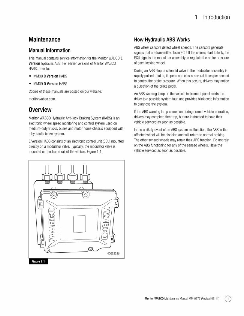
E Version HABS consists of an electronic control unit (ECU) mounted directly on a modulator valve. Typically, the modulator valve is mounted on the frame rail of the vehicle. Figure 1.1.
Figure 1.1
How Hydraulic ABS WorksABS wheel sensors detect wheel speeds. The sensors generate signals that are transmitted to an ECU. If the wheels start to lock, the ECU signals the modulator assembly to regulate the brake pressure of each locking wheel.
During an ABS stop, a solenoid valve in the modulator assembly is rapidly pulsed; that is, it opens and closes several times per second to control the brake pressure. When this occurs, drivers may notice a pulsation of the brake pedal.
An ABS warning lamp on the vehicle instrument panel alerts the driver to a possible system fault and provides blink code information to diagnose the system.
If the ABS warning lamp comes on during normal vehicle operation, drivers may complete their trip, but are instructed to have their vehicle serviced as soon as possible.
In the unlikely event of an ABS system malfunction, the ABS in the affected wheel will be disabled and will return to normal braking. The other sensed wheels may retain their ABS function. Do not rely on the ABS functioning for any of the sensed wheels. Have the vehicle serviced as soon as possible.
Figure 1.1
4006333b
1 Introduction
2 Meritor WABCO Maintenance Manual MM-0677 (Revised 06-11)
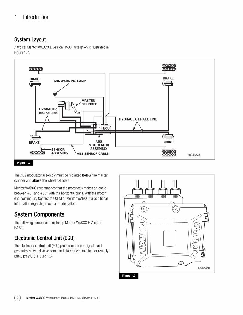
System LayoutA typical Meritor WABCO E Version HABS installation is illustrated in Figure 1.2.
Figure 1.2
The ABS modulator assembly must be mounted below the master cylinder and above the wheel cylinders.
Meritor WABCO recommends that the motor axis makes an angle between +5° and +30° with the horizontal plane, with the motor end pointing up. Contact the OEM or Meritor WABCO for additional information regarding modulator orientation.
System ComponentsThe following components make up Meritor WABCO E Version HABS.
Electronic Control Unit (ECU)The electronic control unit (ECU) processes sensor signals and generates solenoid valve commands to reduce, maintain or reapply brake pressure. Figure 1.3.
Figure 1.3
Figure 1.2
ABS SENSOR CABLE
MASTERCYLINDER
ABS WARNING LAMP
SENSORASSEMBLY
HYDRAULICBRAKE LINE
ABSMODULATORASSEMBLY
ECU
BRAKE
BRAKE
BRAKE
BRAKE
HYDRAULIC BRAKE LINE
1004682d
Figure 1.3
4006333b
1 Introduction
3Meritor WABCO Maintenance Manual MM-0677 (Revised 06-11)
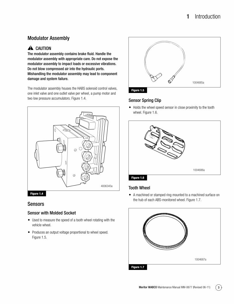
Modulator Assembly
CAUTIONThe modulator assembly contains brake fluid. Handle the modulator assembly with appropriate care. Do not expose the modulator assembly to impact loads or excessive vibrations. Do not blow compressed air into the hydraulic ports. Mishandling the modulator assembly may lead to component damage and system failure.
The modulator assembly houses the HABS solenoid control valves, one inlet valve and one outlet valve per wheel, a pump motor and two low pressure accumulators. Figure 1.4.
Figure 1.4
Sensors
Sensor with Molded Socket
� Used to measure the speed of a tooth wheel rotating with the vehicle wheel.
� Produces an output voltage proportional to wheel speed. Figure 1.5.
Figure 1.5
Sensor Spring Clip
� Holds the wheel speed sensor in close proximity to the tooth wheel. Figure 1.6.
Figure 1.6
Tooth Wheel
� A machined or stamped ring mounted to a machined surface on the hub of each ABS-monitored wheel. Figure 1.7.
Figure 1.7
Figure 1.4
4006345a
Figure 1.5
Figure 1.6
Figure 1.7
1004685a
1004686a
1004687a
1 Introduction
4 Meritor WABCO Maintenance Manual MM-0677 (Revised 06-11)
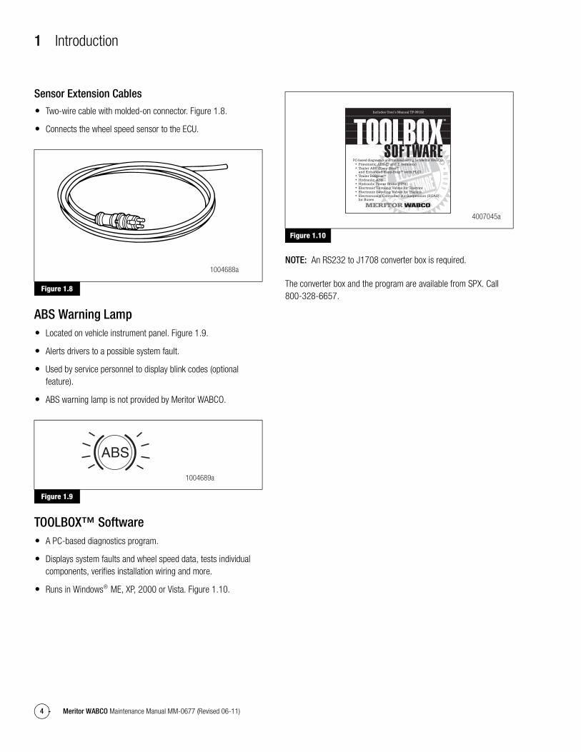
Sensor Extension Cables
� Two-wire cable with molded-on connector. Figure 1.8.
� Connects the wheel speed sensor to the ECU.
Figure 1.8
ABS Warning Lamp� Located on vehicle instrument panel. Figure 1.9.
� Alerts drivers to a possible system fault.
� Used by service personnel to display blink codes (optional feature).
� ABS warning lamp is not provided by Meritor WABCO.
Figure 1.9
TOOLBOX™ Software� A PC-based diagnostics program.
� Displays system faults and wheel speed data, tests individual components, verifies installation wiring and more.
� Runs in Windows® ME, XP, 2000 or Vista. Figure 1.10.
Figure 1.10
NOTE: An RS232 to J1708 converter box is required.
The converter box and the program are available from SPX. Call 800-328-6657.
Figure 1.8
Figure 1.9
1004688a
1004689a
Figure 1.10
4007045a
2 Troubleshooting and Testing
5Meritor WABCO Maintenance Manual MM-0677 (Revised 06-11)
2 Troubleshooting and TestingMaintenance
General InformationThere is no regularly scheduled maintenance required for Meritor WABCO E Version Hydraulic ABS. However, ABS does not change current vehicle maintenance requirements. For example, it is important that the vehicle brake fluid level be correctly maintained.
Wiring Diagrams
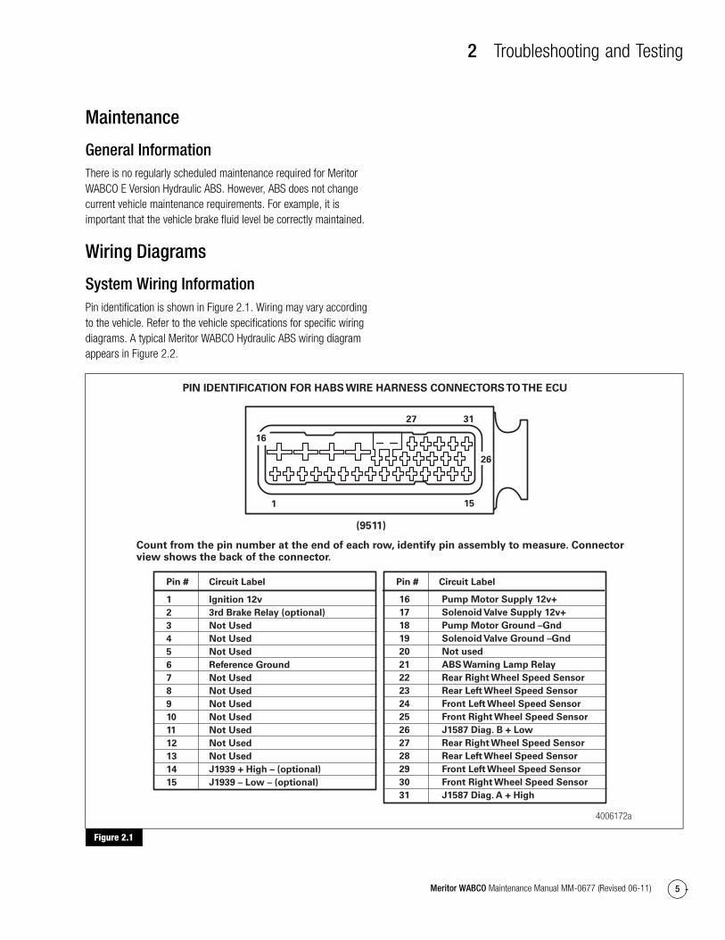
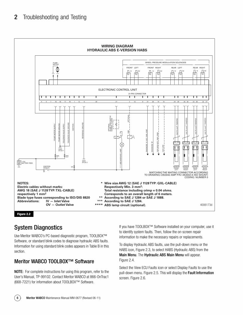
System Wiring InformationPin identification is shown in Figure 2.1. Wiring may vary according to the vehicle. Refer to the vehicle specifications for specific wiring diagrams. A typical Meritor WABCO Hydraulic ABS wiring diagram appears in Figure 2.2.
Figure 2.1
Figure 2.1
4006172a
PIN IDENTIFICATION FOR HABS WIRE HARNESS CONNECTORS TO THE ECU
Count from the pin number at the end of each row, identify pin assembly to measure. Connectorview shows the back of the connector.
1 Ignition 12v
2 3rd Brake Relay (optional)
3 Not Used
4 Not Used
5 Not Used
6 Reference Ground
7 Not Used
8 Not Used
9 Not Used
10 Not Used
11 Not Used
12 Not Used
13 Not Used
14 J1939 + High – (optional)
15 J1939 – Low – (optional)
27
(9511)
31
26
151
16
16 Pump Motor Supply 12v+
17 Solenoid Valve Supply 12v+
18 Pump Motor Ground –Gnd
19 Solenoid Valve Ground –Gnd
20 Not used
21 ABS Warning Lamp Relay
22 Rear Right Wheel Speed Sensor
23 Rear Left Wheel Speed Sensor
24 Front Left Wheel Speed Sensor
25 Front Right Wheel Speed Sensor
26 J1587 Diag. B + Low
27 Rear Right Wheel Speed Sensor
28 Rear Left Wheel Speed Sensor
29 Front Left Wheel Speed Sensor
30 Front Right Wheel Speed Sensor
31 J1587 Diag. A + High
Pin # Circuit LabelPin # Circuit Label
2 Troubleshooting and Testing
6 Meritor WABCO Maintenance Manual MM-0677 (Revised 06-11)
Figure 2.2
System DiagnosticsUse Meritor WABCO’s PC-based diagnostic program, TOOLBOX™ Software, or standard blink codes to diagnose hydraulic ABS faults. Information for using standard blink codes appears in Table B in this section.
Meritor WABCO TOOLBOX™ Software
NOTE: For complete instructions for using this program, refer to the User’s Manual, TP-99102. Contact Meritor WABCO at 866-OnTrac1 (668-7221) for information about TOOLBOX™ Software.
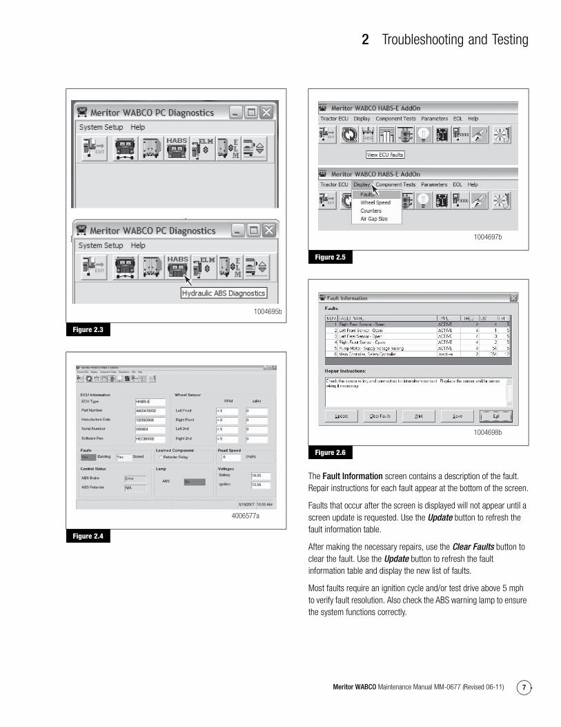
If you have TOOLBOX™ Software installed on your computer, use it to identify system faults. Then, follow the on-screen repair information to make the necessary repairs or replacements.
To display Hydraulic ABS faults, use the pull-down menu or the HABS icon, Figure 2.3, to select HABS (Hydraulic ABS) from the Main Menu. The Hydraulic ABS Main Menu will appear. Figure 2.4.
Select the View ECU Faults icon or select Display Faults to use the pull-down menu. Figure 2.5. This will display the Fault Information screen. Figure 2.6.
Figure 2.2
4006173d
WHEEL PRESSURE MODULATION SOLENOIDS
ELECTRONIC CONTROL UNIT31-PIN CONNECTOR
FRONT LEFT
IV
PUMP–MOTOR
GNDSTUD 2
SENSORFRONTLEFT
SENSORFRONTRIGHT
SENSORREARLEFT
SENSORREARRIGHT
MATCHING THE MATING CONNECTOR ACCORDINGTO DRAWING C953042 AMP P/N I-953042-6 (NO SHUNT)
CODING: NUMBER 0
GNDSTUD 1
+12VBATTERY FEED12V
30
+
–
30A**
25A***
5AIGNITIONSWITCH
DB
RO
PT
ION
AL
****
AB
S W
AR
NIN
G L
AM
P
OP
TIO
NA
LB
LIN
K C
OD
E S
WIT
CH
NO
RM
AL
CLO
SE
D
DIA
GN
OS
E "
A"
AC
C. S
AE
J15
87
DIA
GN
OS
E "
B"
CA
N H
IGH
AC
C. S
AE
J19
39
CA
N L
OW
2x0.
75 m
m2
TW
IST
ED
2x0.
75 m
m2
TW
IST
ED
2x0.
75 m
m2
TW
IST
ED
2x0.
75 m
m2
TW
IST
ED
IGN
ITIO
N
RE
FER
EN
CE
GR
OU
ND
*PU
MP
MO
TOR
SU
PP
LY
*PU
MP
MO
TOR
GR
OU
ND
*SO
LEN
OID
VA
LVE
SU
PP
LY
*SO
LEN
OID
VA
LVE
GR
OU
ND
4 5 7 16 18 17 19 1 12 6 20 21 2 13 319 26 14 15 24 29 25 30 23 28 22 27
OV IV OV IV OV IV OV
FRONT RIGHT REAR RIGHTREAR LEFT
WIRING DIAGRAMHYDRAULIC ABS E-VERSION HABS
NOTES:Electric cables without marks:AWG 18 (SAE J 1128 TYP: TXL-CABLE) respectively 1 mm2
Blade type fuses corresponding to ISO/DIS 8820Abbreviations: IV — Inlet Valve OV — Outlet Valve
* Wire size AWG 12 (SAE J 1128 TYP: GXL-CABLE) Respectively Min. 3 mm2: Total resistance including crimp = 0.04 ohms. Corresponds to an overall length of 6 meters. ** According to SAE J 1284 or SAE J 1888. *** According to SAE J 1284.
**** ABS lamp circuit (optional).
2 Troubleshooting and Testing
7Meritor WABCO Maintenance Manual MM-0677 (Revised 06-11)
Figure 2.3
Figure 2.4
Figure 2.5
Figure 2.6
The Fault Information screen contains a description of the fault. Repair instructions for each fault appear at the bottom of the screen.
Faults that occur after the screen is displayed will not appear until a screen update is requested. Use the Update button to refresh the fault information table.
After making the necessary repairs, use the Clear Faults button to clear the fault. Use the Update button to refresh the fault information table and display the new list of faults.
Most faults require an ignition cycle and/or test drive above 5 mph to verify fault resolution. Also check the ABS warning lamp to ensure the system functions correctly.
Figure 2.3
Figure 2.4
1004695b
4006577a
Figure 2.5
Figure 2.6
1004697b
1004698b
2 Troubleshooting and Testing
8 Meritor WABCO Maintenance Manual MM-0677 (Revised 06-11)
Blink Code Diagnostics
Definitions
ABS Warning Lamp: This lamp, located on the vehicle instrument panel, serves two purposes:
1. Alerts drivers or service personnel to a possible fault in the hydraulic ABS, as follows:
IF the ABS warning lamp comes on briefly then goes OFF when the ignition is turned ON . . . . . there are no active faults in the hydraulic ABS
IF the ABS warning lamp comes on and stays on AFTER the ignition is turned ON and
The vehicle is driven in excess of four mph (6 km/h) . . . There may be an active fault in the hydraulic ABS
IF the ABS warning lamp comes on and stays on and
Goes OFF after the vehicle is driven in excess of four mph (6 km/h) or illuminates intermittently during driving . . . There may be a stored fault in the hydraulic ABS
2. Displays diagnostic blink codes for easy servicing.
Blink Code: A series of blinks or flashes that describe a particular ABS system condition. Refer to Table B and Table C in this section for blink code identification.
Blink Code Diagnostics: The ability of the Meritor WABCO ECU to sense faults in the ABS system and to define these faults via blink codes.
Blink Code Switch: A momentary switch that activates blink code diagnostic capabilities. Usually, it is mounted under the instrument panel or on the steering column. Refer to the vehicle specifications for type and location.
Clearing Fault Codes: The process of erasing faults from the ECU memory bank. Refer to Table B in this section.
Fault Code: An ABS condition (fault) detected and stored in memory by the Meritor WABCO ECU and displayed by blink code. System faults may be Active or Stored.
Active Fault: A condition that currently exists in the ABS system; for example, a sensor circuit malfunction on the left front steering axle. An active fault must be repaired before you can display additional faults. Once an active fault has been repaired, it becomes a stored fault.
Stored Fault: A condition that caused the system to register a fault, but is not currently active. For example, a loose wire that corrected itself. A stored fault can also be an active fault that has been corrected. Refer to Active Fault.
Table B, in this section, describes the method of distinguishing between active and stored faults and explains how to clear them.
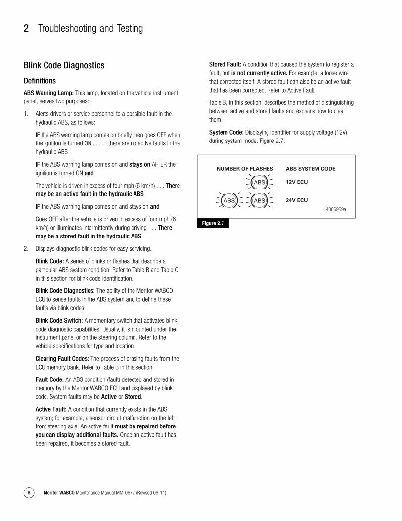
System Code: Displaying identifier for supply voltage (12V) during system mode. Figure 2.7.
Figure 2.7
Figure 2.7
4006959a
NUMBER OF FLASHES ABS SYSTEM CODE
12V ECU
24V ECU
2 Troubleshooting and Testing
9Meritor WABCO Maintenance Manual MM-0677 (Revised 06-11)
Using Blink Code Diagnostics — Optional FeatureFollow the steps listed in Table B to use blink code diagnostics. Refer to Figure 2.15 and Figure 2.16 in this section for blink code illustrations.
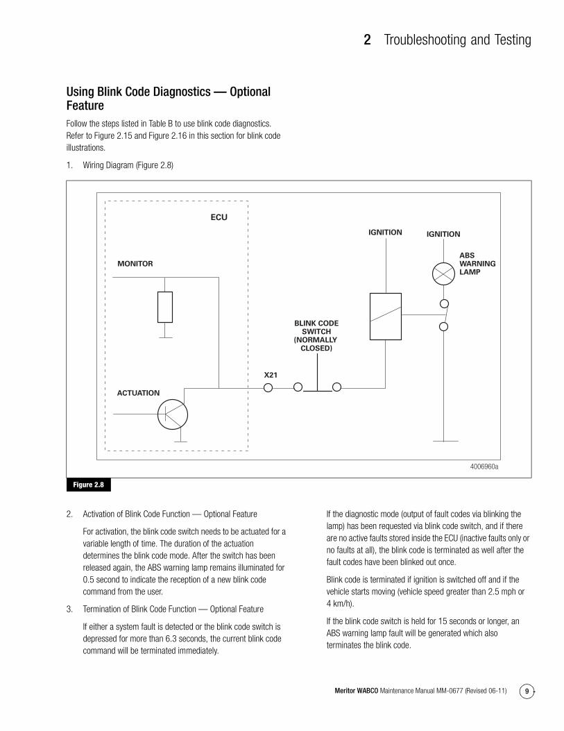
1. Wiring Diagram (Figure 2.8)
Figure 2.8
2. Activation of Blink Code Function — Optional Feature
For activation, the blink code switch needs to be actuated for a variable length of time. The duration of the actuation determines the blink code mode. After the switch has been released again, the ABS warning lamp remains illuminated for 0.5 second to indicate the reception of a new blink code command from the user.
3. Termination of Blink Code Function — Optional Feature
If either a system fault is detected or the blink code switch is depressed for more than 6.3 seconds, the current blink code command will be terminated immediately.
If the diagnostic mode (output of fault codes via blinking the lamp) has been requested via blink code switch, and if there are no active faults stored inside the ECU (inactive faults only or no faults at all), the blink code is terminated as well after the fault codes have been blinked out once.
Blink code is terminated if ignition is switched off and if the vehicle starts moving (vehicle speed greater than 2.5 mph or 4 km/h).
If the blink code switch is held for 15 seconds or longer, an ABS warning lamp fault will be generated which also terminates the blink code.
Figure 2.8
4006960a
MONITOR
BLINK CODESWITCH
(NORMALLY CLOSED)
ACTUATION
ECU
X21
ABSWARNINGLAMP
IGNITION IGNITION
2 Troubleshooting and Testing
10 Meritor WABCO Maintenance Manual MM-0677 (Revised 06-11)
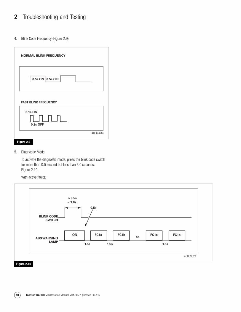
4. Blink Code Frequency (Figure 2.9)
Figure 2.9
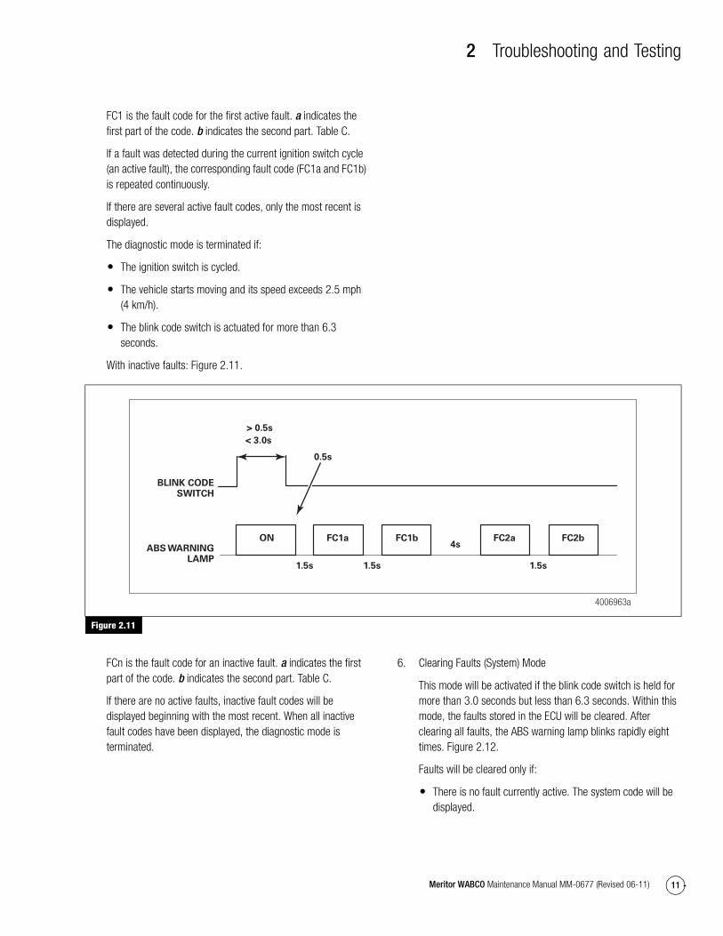
5. Diagnostic Mode
To activate the diagnostic mode, press the blink code switch for more than 0.5 second but less than 3.0 seconds. Figure 2.10.
With active faults:
Figure 2.10
Figure 2.9
4006961a
0.5s ON
0.1s ON
0.5s OFF
0.2s OFF
FAST BLINK FREQUENCY
NORMAL BLINK FREQUENCY
Figure 2.10
4006962a
FC1b FC1bFC1a FC1aONABS WARNING
LAMP
BLINK CODESWITCH
> 0.5s
< 3.0s
0.5s
1.5s 1.5s 1.5s
4s
2 Troubleshooting and Testing
11Meritor WABCO Maintenance Manual MM-0677 (Revised 06-11)
FC1 is the fault code for the first active fault. a indicates the first part of the code. b indicates the second part. Table C.
If a fault was detected during the current ignition switch cycle (an active fault), the corresponding fault code (FC1a and FC1b) is repeated continuously.
If there are several active fault codes, only the most recent is displayed.
The diagnostic mode is terminated if:
� The ignition switch is cycled.
� The vehicle starts moving and its speed exceeds 2.5 mph (4 km/h).
� The blink code switch is actuated for more than 6.3 seconds.
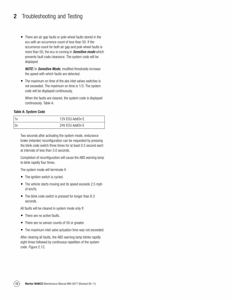
With inactive faults: Figure 2.11.
Figure 2.11
FCn is the fault code for an inactive fault. a indicates the first part of the code. b indicates the second part. Table C.
If there are no active faults, inactive fault codes will be displayed beginning with the most recent. When all inactive fault codes have been displayed, the diagnostic mode is terminated.
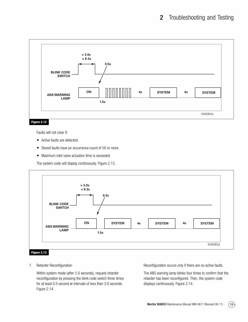
6. Clearing Faults (System) Mode
This mode will be activated if the blink code switch is held for more than 3.0 seconds but less than 6.3 seconds. Within this mode, the faults stored in the ECU will be cleared. After clearing all faults, the ABS warning lamp blinks rapidly eight times. Figure 2.12.
Faults will be cleared only if:
� There is no fault currently active. The system code will be displayed.
Figure 2.11
4006963a
FC1b FC2bFC1a FC2aON
> 0.5s
< 3.0s
0.5s
1.5s 1.5s 1.5s
4sABS WARNINGLAMP
BLINK CODESWITCH
2 Troubleshooting and Testing
12 Meritor WABCO Maintenance Manual MM-0677 (Revised 06-11)
� There are air gap faults or pole wheel faults stored in the ecu with an occurrence count of less than 50. If the occurrence count for both air gap and pole wheel faults is more than 50, the ecu is running in Sensitive mode which prevents fault code clearance. The system code will be displayed.
NOTE: In Sensitive Mode, modified thresholds increase the speed with which faults are detected.
� The maximum on time of the abs inlet valves switches is not exceeded. The maximum on time is 1/3. The system code will be displayed continuously.
When the faults are cleared, the system code is displayed continuously. Table A.
Table A: System Code
Two seconds after activating the system mode, endurance brake (retarder) reconfiguration can be requested by pressing the blink code switch three times for at least 0.5 second each at intervals of less than 3.0 seconds.
Completion of reconfiguration will cause the ABS warning lamp to blink rapidly four times.
The system mode will terminate if:
� The ignition switch is cycled.
� The vehicle starts moving and its speed exceeds 2.5 mph (4 km/h).
� The blink code switch is pressed for longer than 6.3 seconds.
All faults will be cleared in system mode only if:
� There are no active faults.
� There are no sensor counts of 50 or greater.
� The maximum inlet valve actuation time was not exceeded.
After clearing all faults, the ABS warning lamp blinks rapidly eight times followed by continuous repetition of the system code. Figure 2.12.
1x 12V ECU AddOn E
2x 24V ECU AddOn E
2 Troubleshooting and Testing
13Meritor WABCO Maintenance Manual MM-0677 (Revised 06-11)
Figure 2.12
Faults will not clear if:
� Active faults are detected.
� Stored faults have an occurrence count of 50 or more.
� Maximum inlet valve actuation time is exceeded.
The system code will display continuously. Figure 2.13.
Figure 2.13
7. Retarder Reconfiguration
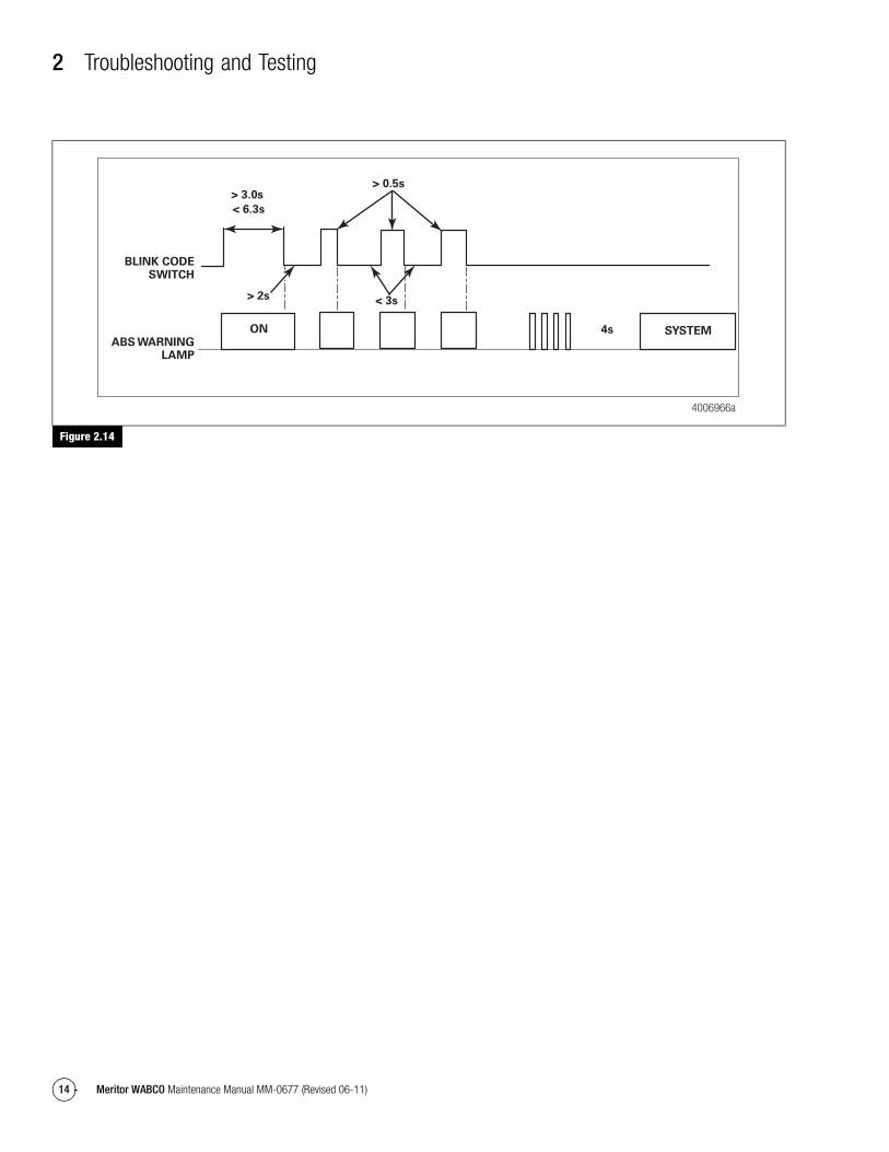
Within system mode (after 2.0 seconds), request retarder reconfiguration by pressing the blink code switch three times for at least 0.5 second at intervals of less than 3.0 seconds. Figure 2.14.
Reconfiguration occurs only if there are no active faults.
The ABS warning lamp blinks four times to confirm that the retarder has been reconfigured. Then, the system code displays continuously. Figure 2.14.
Figure 2.12
4006964a
SYSTEM SYSTEMON
> 3.0s
< 6.3s
0.5s
1.5s
4s4sABS WARNING
LAMP
BLINK CODESWITCH
Figure 2.13
> 3.0s
< 6.3s
SYSTEM SYSTEM SYSTEM
4006965a
ON
0.5s
1.5s
4s 4sABS WARNING
LAMP
BLINK CODESWITCH
2 Troubleshooting and Testing
14 Meritor WABCO Maintenance Manual MM-0677 (Revised 06-11)
Figure 2.14
Figure 2.14
> 3.0s
< 6.3s
SYSTEM
4006966a
ON
> 0.5s
> 2s < 3s
4sABS WARNING
LAMP
BLINK CODESWITCH
2 Troubleshooting and Testing
15Meritor WABCO Maintenance Manual MM-0677 (Revised 06-11)
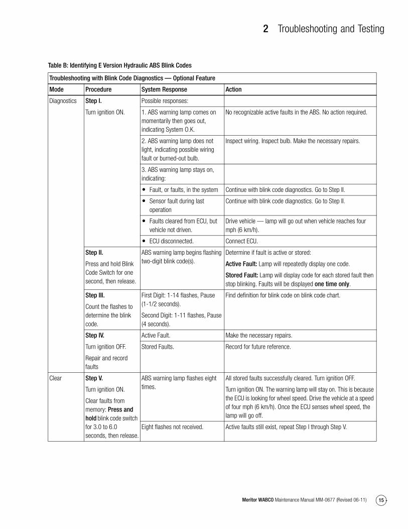
Table B: Identifying E Version Hydraulic ABS Blink Codes
Troubleshooting with Blink Code Diagnostics — Optional Feature
Mode Procedure System Response Action
Diagnostics Step I.
Turn ignition ON.
Possible responses:
1. ABS warning lamp comes on momentarily then goes out, indicating System O.K.
No recognizable active faults in the ABS. No action required.
2. ABS warning lamp does not light, indicating possible wiring fault or burned-out bulb.
Inspect wiring. Inspect bulb. Make the necessary repairs.
3. ABS warning lamp stays on, indicating:
� Fault, or faults, in the system Continue with blink code diagnostics. Go to Step II.
� Sensor fault during last operation
Continue with blink code diagnostics. Go to Step II.
� Faults cleared from ECU, but vehicle not driven.
Drive vehicle — lamp will go out when vehicle reaches four mph (6 km/h).
� ECU disconnected. Connect ECU.
Step II.
Press and hold Blink Code Switch for one second, then release.
ABS warning lamp begins flashing two-digit blink code(s).
Determine if fault is active or stored:
Active Fault: Lamp will repeatedly display one code.
Stored Fault: Lamp will display code for each stored fault then stop blinking. Faults will be displayed one time only.
Step III.
Count the flashes to determine the blink code.
First Digit: 1-14 flashes, Pause (1-1/2 seconds).
Second Digit: 1-11 flashes, Pause (4 seconds).
Find definition for blink code on blink code chart.
Step IV.
Turn ignition OFF.
Repair and record faults
Active Fault. Make the necessary repairs.
Stored Faults. Record for future reference.
Clear Step V.
Turn ignition ON.
Clear faults from memory: Press and hold blink code switch for 3.0 to 6.0 seconds, then release.
ABS warning lamp flashes eight times.
All stored faults successfully cleared. Turn ignition OFF.
Turn ignition ON. The warning lamp will stay on. This is because the ECU is looking for wheel speed. Drive the vehicle at a speed of four mph (6 km/h). Once the ECU senses wheel speed, the lamp will go off.
Eight flashes not received. Active faults still exist, repeat Step I through Step V.
2 Troubleshooting and Testing
16 Meritor WABCO Maintenance Manual MM-0677 (Revised 06-11)
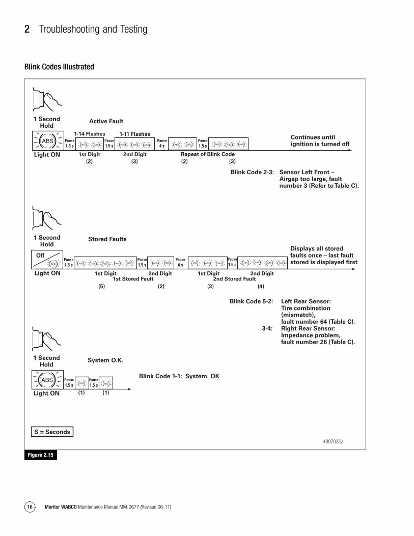
Blink Codes Illustrated
Figure 2.15
Figure 2.15
Pause1.5 s
Pause1.5 s
1-14 Flashes
Pause1.5 s
Pause4 s
1-11 Flashes
Light ON
Active Fault
Pause1.5 s
Pause1.5 s
Light ON
1 SecondHold
1 SecondHold
System O.K.
Continues untilignition is turned off
1st Digit
(2) (3) (2) (3)
(5)
(1) (1)
(2) (3) (4)
2nd Digit
Pause1.5 s
Pause1.5 s
Pause1.5 s
Pause4 s
Light ON
Off
Stored Faults
S = Seconds
Displays all storedfaults once – last faultstored is displayed first
Blink Code 2-3: Sensor Left Front – Airgap too large, fault number 3 (Refer to Table C).
Blink Code 5-2: Left Rear Sensor: Tire combination (mismatch), fault number 64 (Table C). 3-4: Right Rear Sensor: Impedance problem, fault number 26 (Table C).
Blink Code 1-1: System OK
1st Digit 2nd Digit 1st Digit 2nd Digit1st Stored Fault 2nd Stored Fault
Repeat of Blink Code
1 SecondHold
4007035a
2 Troubleshooting and Testing
17Meritor WABCO Maintenance Manual MM-0677 (Revised 06-11)
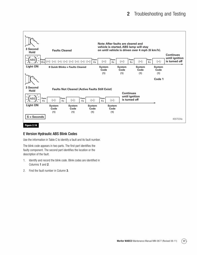
Figure 2.16
E Version Hydraulic ABS Blink Codes
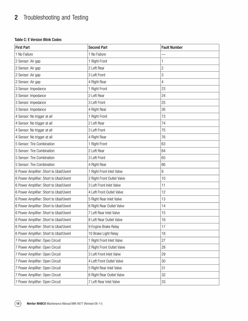
Use the information in Table C to identify a fault and its fault number.
The blink code appears in two parts. The first part identifies the faulty component. The second part identifies the location or the description of the fault.
1. Identify and record the blink code. Blink codes are identified in Columns 1 and 2.
2. Find the fault number in Column 3.
Figure 2.16
Pause1.5 s
Pause4 s
Pause4 s
Light ON
Faults Cleared
Pause4 s
Pause4 s
Pause4 s
Pause4 s
Light ON
Faults Not Cleared (Active Faults Still Exist)3 Second
Hold
3 SecondHold
Continuesuntil ignitionis turned off
Note: After faults are cleared andvehicle is started, ABS lamp will stayon until vehicle is driven over 4 mph (6 km/h).
Continuesuntil ignitionis turned off
8 Quick Blinks = Faults Cleared
(1)
SystemCode
Pause4 s
Pause4 s
Code 1
4007034aS = Seconds
(1)
SystemCode
(1)
SystemCode
(1)
SystemCode
(1)
SystemCode
(1)
SystemCode
(1)
SystemCode
(1)
SystemCode
2 Troubleshooting and Testing
18 Meritor WABCO Maintenance Manual MM-0677 (Revised 06-11)
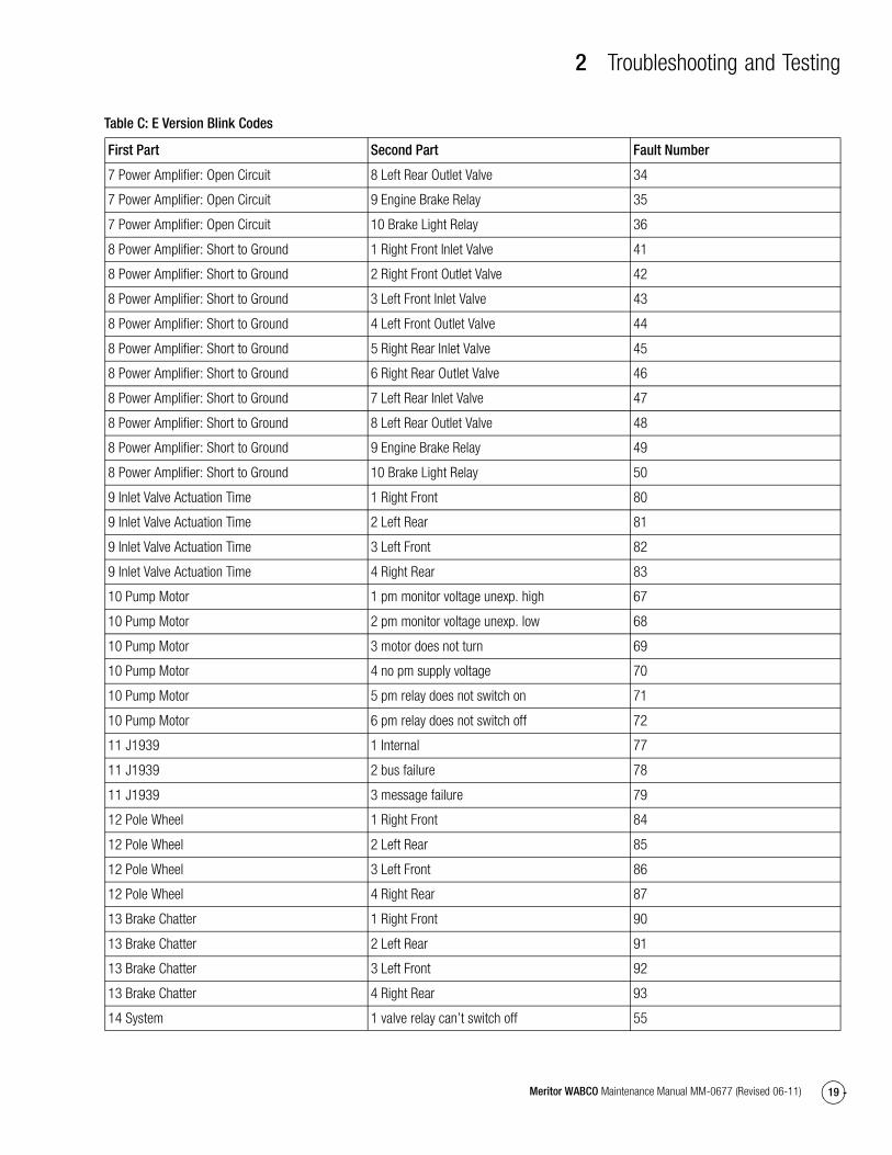
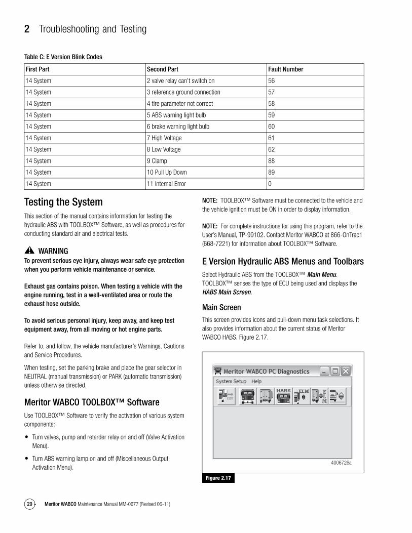
Table C: E Version Blink Codes
First Part Second Part Fault Number
1 No Failure 1 No Failure —
2 Sensor: Air gap 1 Right Front 1
2 Sensor: Air gap 2 Left Rear 2
2 Sensor: Air gap 3 Left Front 3
2 Sensor: Air gap 4 Right Rear 4
3 Sensor: Impedance 1 Right Front 23
3 Sensor: Impedance 2 Left Rear 24
3 Sensor: Impedance 3 Left Front 25
3 Sensor: Impedance 4 Right Rear 26
4 Sensor: No trigger at all 1 Right Front 73
4 Sensor: No trigger at all 2 Left Rear 74
4 Sensor: No trigger at all 3 Left Front 75
4 Sensor: No trigger at all 4 Right Rear 76
5 Sensor: Tire Combination 1 Right Front 63
5 Sensor: Tire Combination 2 Left Rear 64
5 Sensor: Tire Combination 3 Left Front 65
5 Sensor: Tire Combination 4 Right Rear 66
6 Power Amplifier: Short to Ubat/Uvent 1 Right Front Inlet Valve 9
6 Power Amplifier: Short to Ubat/Uvent 2 Right Front Outlet Valve 10
6 Power Amplifier: Short to Ubat/Uvent 3 Left Front Inlet Valve 11
6 Power Amplifier: Short to Ubat/Uvent 4 Left Front Outlet Valve 12
6 Power Amplifier: Short to Ubat/Uvent 5 Right Rear Inlet Valve 13
6 Power Amplifier: Short to Ubat/Uvent 6 Right Rear Outlet Valve 14
6 Power Amplifier: Short to Ubat/Uvent 7 Left Rear Inlet Valve 15
6 Power Amplifier: Short to Ubat/Uvent 8 Left Rear Outlet Valve 16
6 Power Amplifier: Short to Ubat/Uvent 9 Engine Brake Relay 17
6 Power Amplifier: Short to Ubat/Uvent 10 Brake Light Relay 18
7 Power Amplifier: Open Circuit 1 Right Front Inlet Valve 27
7 Power Amplifier: Open Circuit 2 Right Front Outlet Valve 28
7 Power Amplifier: Open Circuit 3 Left Front Inlet Valve 29
7 Power Amplifier: Open Circuit 4 Left Front Outlet Valve 30
7 Power Amplifier: Open Circuit 5 Right Rear Inlet Valve 31
7 Power Amplifier: Open Circuit 6 Right Rear Outlet Valve 32
7 Power Amplifier: Open Circuit 7 Left Rear Inlet Valve 33
2 Troubleshooting and Testing
19Meritor WABCO Maintenance Manual MM-0677 (Revised 06-11)
7 Power Amplifier: Open Circuit 8 Left Rear Outlet Valve 34
7 Power Amplifier: Open Circuit 9 Engine Brake Relay 35
7 Power Amplifier: Open Circuit 10 Brake Light Relay 36
8 Power Amplifier: Short to Ground 1 Right Front Inlet Valve 41
8 Power Amplifier: Short to Ground 2 Right Front Outlet Valve 42
8 Power Amplifier: Short to Ground 3 Left Front Inlet Valve 43
8 Power Amplifier: Short to Ground 4 Left Front Outlet Valve 44
8 Power Amplifier: Short to Ground 5 Right Rear Inlet Valve 45
8 Power Amplifier: Short to Ground 6 Right Rear Outlet Valve 46
8 Power Amplifier: Short to Ground 7 Left Rear Inlet Valve 47
8 Power Amplifier: Short to Ground 8 Left Rear Outlet Valve 48
8 Power Amplifier: Short to Ground 9 Engine Brake Relay 49
8 Power Amplifier: Short to Ground 10 Brake Light Relay 50
9 Inlet Valve Actuation Time 1 Right Front 80
9 Inlet Valve Actuation Time 2 Left Rear 81
9 Inlet Valve Actuation Time 3 Left Front 82
9 Inlet Valve Actuation Time 4 Right Rear 83
10 Pump Motor 1 pm monitor voltage unexp. high 67
10 Pump Motor 2 pm monitor voltage unexp. low 68
10 Pump Motor 3 motor does not turn 69
10 Pump Motor 4 no pm supply voltage 70
10 Pump Motor 5 pm relay does not switch on 71
10 Pump Motor 6 pm relay does not switch off 72
11 J1939 1 Internal 77
11 J1939 2 bus failure 78
11 J1939 3 message failure 79
12 Pole Wheel 1 Right Front 84
12 Pole Wheel 2 Left Rear 85
12 Pole Wheel 3 Left Front 86
12 Pole Wheel 4 Right Rear 87
13 Brake Chatter 1 Right Front 90
13 Brake Chatter 2 Left Rear 91
13 Brake Chatter 3 Left Front 92
13 Brake Chatter 4 Right Rear 93
14 System 1 valve relay can’t switch off 55
First Part Second Part Fault Number
Table C: E Version Blink Codes
2 Troubleshooting and Testing
20 Meritor WABCO Maintenance Manual MM-0677 (Revised 06-11)
Testing the SystemThis section of the manual contains information for testing the hydraulic ABS with TOOLBOX™ Software, as well as procedures for conducting standard air and electrical tests.
WARNINGTo prevent serious eye injury, always wear safe eye protection when you perform vehicle maintenance or service.
Exhaust gas contains poison. When testing a vehicle with the engine running, test in a well-ventilated area or route the exhaust hose outside.
To avoid serious personal injury, keep away, and keep test equipment away, from all moving or hot engine parts.
Refer to, and follow, the vehicle manufacturer’s Warnings, Cautions and Service Procedures.
When testing, set the parking brake and place the gear selector in NEUTRAL (manual transmission) or PARK (automatic transmission) unless otherwise directed.
Meritor WABCO TOOLBOX™ SoftwareUse TOOLBOX™ Software to verify the activation of various system components:
� Turn valves, pump and retarder relay on and off (Valve Activation Menu).
� Turn ABS warning lamp on and off (Miscellaneous Output Activation Menu).
NOTE: TOOLBOX™ Software must be connected to the vehicle and the vehicle ignition must be ON in order to display information.
NOTE: For complete instructions for using this program, refer to the User’s Manual, TP-99102. Contact Meritor WABCO at 866-OnTrac1 (668-7221) for information about TOOLBOX™ Software.
E Version Hydraulic ABS Menus and ToolbarsSelect Hydraulic ABS from the TOOLBOX™ Main Menu. TOOLBOX™ senses the type of ECU being used and displays the HABS Main Screen.
Main Screen
This screen provides icons and pull-down menu task selections. It also provides information about the current status of Meritor WABCO HABS. Figure 2.17.
Figure 2.17
14 System 2 valve relay can’t switch on 56
14 System 3 reference ground connection 57
14 System 4 tire parameter not correct 58
14 System 5 ABS warning light bulb 59
14 System 6 brake warning light bulb 60
14 System 7 High Voltage 61
14 System 8 Low Voltage 62
14 System 9 Clamp 88
14 System 10 Pull Up Down 89
14 System 11 Internal Error 0
First Part Second Part Fault Number
Figure 2.17
4006726a
Table C: E Version Blink Codes
2 Troubleshooting and Testing
21Meritor WABCO Maintenance Manual MM-0677 (Revised 06-11)
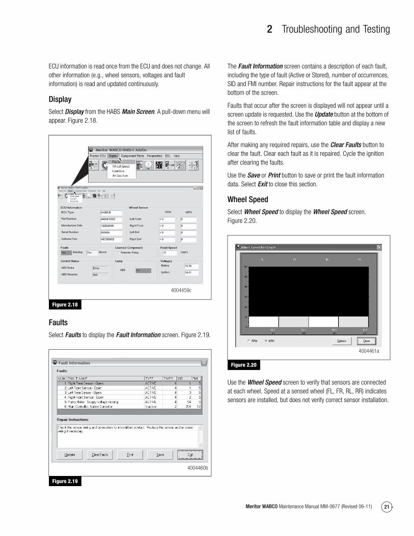
ECU information is read once from the ECU and does not change. All other information (e.g., wheel sensors, voltages and fault information) is read and updated continuously.
Display
Select Display from the HABS Main Screen. A pull-down menu will appear. Figure 2.18.
Figure 2.18
Faults
Select Faults to display the Fault Information screen. Figure 2.19.
Figure 2.19
The Fault Information screen contains a description of each fault, including the type of fault (Active or Stored), number of occurrences, SID and FMI number. Repair instructions for the fault appear at the bottom of the screen.
Faults that occur after the screen is displayed will not appear until a screen update is requested. Use the Update button at the bottom of the screen to refresh the fault information table and display a new list of faults.
After making any required repairs, use the Clear Faults button to clear the fault. Clear each fault as it is repaired. Cycle the ignition after clearing the faults.
Use the Save or Print button to save or print the fault information data. Select Exit to close this section.
Wheel Speed
Select Wheel Speed to display the Wheel Speed screen. Figure 2.20.
Figure 2.20
Use the Wheel Speed screen to verify that sensors are connected at each wheel. Speed at a sensed wheel (FL, FR, RL, RR) indicates sensors are installed, but does not verify correct sensor installation.
Figure 2.18
Figure 2.19
4004459c
4004460b
Figure 2.20
4004461a
2 Troubleshooting and Testing
22 Meritor WABCO Maintenance Manual MM-0677 (Revised 06-11)
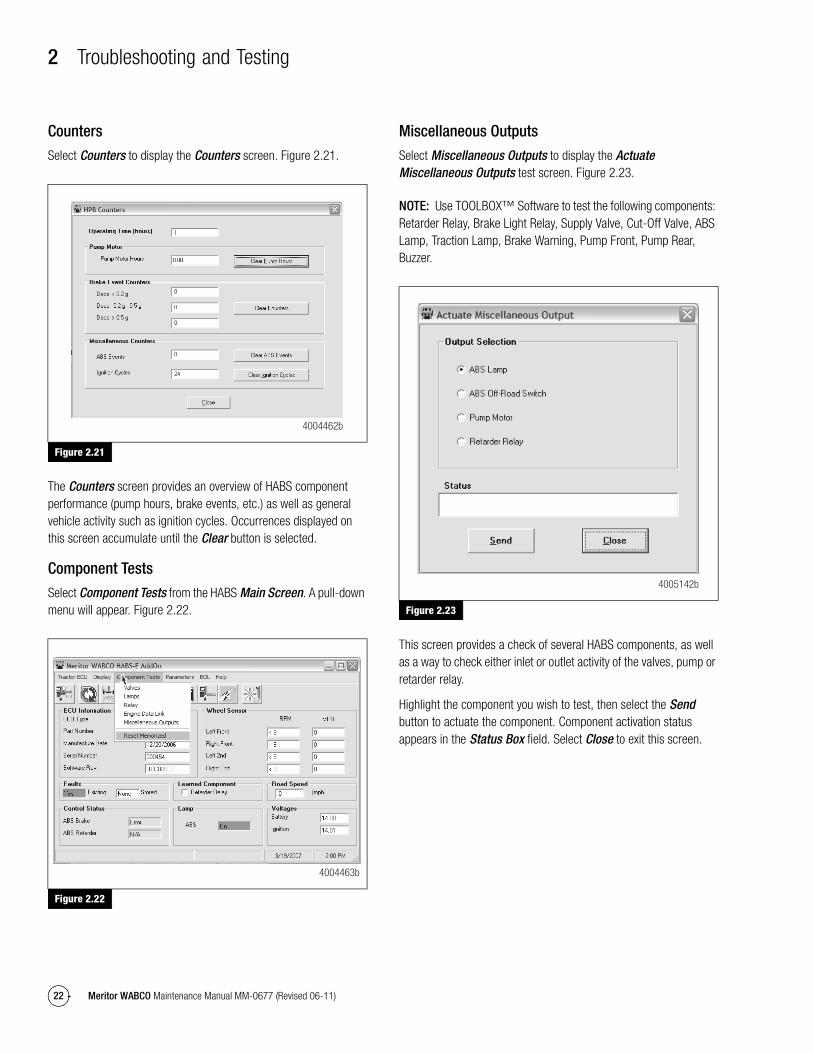
Counters
Select Counters to display the Counters screen. Figure 2.21.
Figure 2.21
The Counters screen provides an overview of HABS component performance (pump hours, brake events, etc.) as well as general vehicle activity such as ignition cycles. Occurrences displayed on this screen accumulate until the Clear button is selected.
Component Tests
Select Component Tests from the HABS Main Screen. A pull-down menu will appear. Figure 2.22.
Figure 2.22
Miscellaneous Outputs
Select Miscellaneous Outputs to display the Actuate Miscellaneous Outputs test screen. Figure 2.23.
NOTE: Use TOOLBOX™ Software to test the following components: Retarder Relay, Brake Light Relay, Supply Valve, Cut-Off Valve, ABS Lamp, Traction Lamp, Brake Warning, Pump Front, Pump Rear, Buzzer.
Figure 2.23
This screen provides a check of several HABS components, as well as a way to check either inlet or outlet activity of the valves, pump or retarder relay.
Highlight the component you wish to test, then select the Send button to actuate the component. Component activation status appears in the Status Box field. Select Close to exit this screen.
Figure 2.21
Figure 2.22
4004462b
4004463b
Figure 2.23
4005142b
2 Troubleshooting and Testing
23Meritor WABCO Maintenance Manual MM-0677 (Revised 06-11)
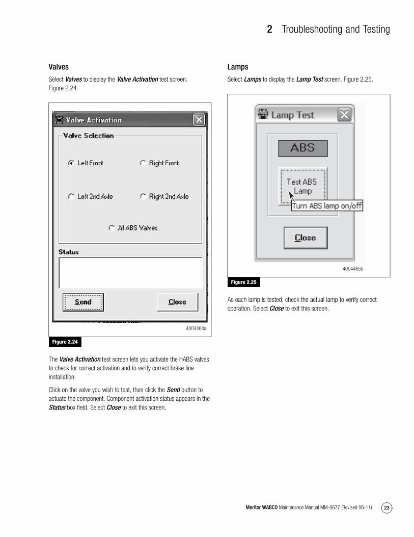
Valves
Select Valves to display the Valve Activation test screen. Figure 2.24.
Figure 2.24
The Valve Activation test screen lets you activate the HABS valves to check for correct activation and to verify correct brake line installation.
Click on the valve you wish to test, then click the Send button to actuate the component. Component activation status appears in the Status box field. Select Close to exit this screen.
Lamps
Select Lamps to display the Lamp Test screen. Figure 2.25.
Figure 2.25
As each lamp is tested, check the actual lamp to verify correct operation. Select Close to exit this screen.
Figure 2.24
4004464a
Figure 2.25
4004465b
2 Troubleshooting and Testing
24 Meritor WABCO Maintenance Manual MM-0677 (Revised 06-11)
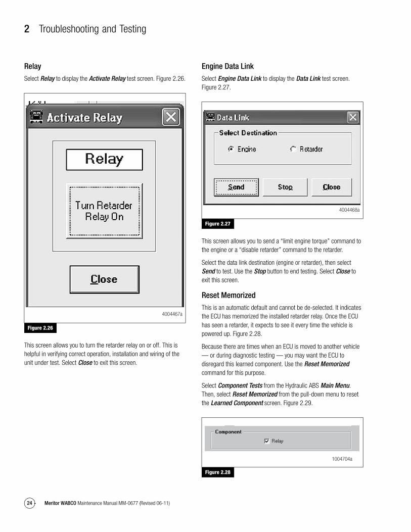
Relay
Select Relay to display the Activate Relay test screen. Figure 2.26.
Figure 2.26
This screen allows you to turn the retarder relay on or off. This is helpful in verifying correct operation, installation and wiring of the unit under test. Select Close to exit this screen.
Engine Data Link
Select Engine Data Link to display the Data Link test screen. Figure 2.27.
Figure 2.27
This screen allows you to send a “limit engine torque” command to the engine or a “disable retarder” command to the retarder.
Select the data link destination (engine or retarder), then select Send to test. Use the Stop button to end testing. Select Close to exit this screen.
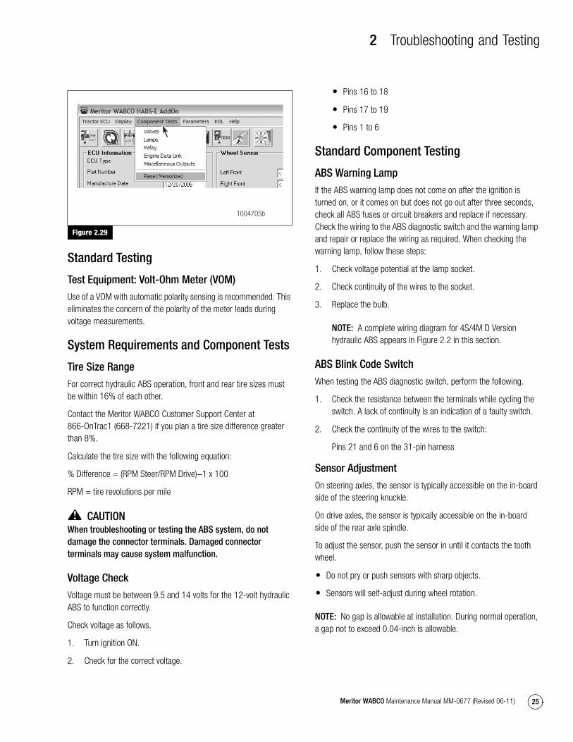
Reset Memorized
This is an automatic default and cannot be de-selected. It indicates the ECU has memorized the installed retarder relay. Once the ECU has seen a retarder, it expects to see it every time the vehicle is powered up. Figure 2.28.
Because there are times when an ECU is moved to another vehicle — or during diagnostic testing — you may want the ECU to disregard this learned component. Use the Reset Memorized command for this purpose.
Select Component Tests from the Hydraulic ABS Main Menu. Then, select Reset Memorized from the pull-down menu to reset the Learned Component screen. Figure 2.29.
Figure 2.28
Figure 2.26
4004467a
Figure 2.27
Figure 2.28
4004468a
1004704a
2 Troubleshooting and Testing
25Meritor WABCO Maintenance Manual MM-0677 (Revised 06-11)
Figure 2.29
Standard Testing
Test Equipment: Volt-Ohm Meter (VOM)
Use of a VOM with automatic polarity sensing is recommended. This eliminates the concern of the polarity of the meter leads during voltage measurements.
System Requirements and Component Tests
Tire Size Range
For correct hydraulic ABS operation, front and rear tire sizes must be within 16% of each other.
Contact the Meritor WABCO Customer Support Center at 866-OnTrac1 (668-7221) if you plan a tire size difference greater than 8%.
Calculate the tire size with the following equation:
% Difference = (RPM Steer/RPM Drive)−1 x 100
RPM = tire revolutions per mile
CAUTIONWhen troubleshooting or testing the ABS system, do not damage the connector terminals. Damaged connector terminals may cause system malfunction.
Voltage Check
Voltage must be between 9.5 and 14 volts for the 12-volt hydraulic ABS to function correctly.
Check voltage as follows.
1. Turn ignition ON.
2. Check for the correct voltage.
� Pins 16 to 18
� Pins 17 to 19
� Pins 1 to 6
Standard Component Testing
ABS Warning Lamp
If the ABS warning lamp does not come on after the ignition is turned on, or it comes on but does not go out after three seconds, check all ABS fuses or circuit breakers and replace if necessary. Check the wiring to the ABS diagnostic switch and the warning lamp and repair or replace the wiring as required. When checking the warning lamp, follow these steps:
1. Check voltage potential at the lamp socket.
2. Check continuity of the wires to the socket.
3. Replace the bulb.
NOTE: A complete wiring diagram for 4S/4M D Version hydraulic ABS appears in Figure 2.2 in this section.
ABS Blink Code Switch
When testing the ABS diagnostic switch, perform the following.
1. Check the resistance between the terminals while cycling the switch. A lack of continuity is an indication of a faulty switch.
2. Check the continuity of the wires to the switch:
Pins 21 and 6 on the 31-pin harness
Sensor Adjustment
On steering axles, the sensor is typically accessible on the in-board side of the steering knuckle.
On drive axles, the sensor is typically accessible on the in-board side of the rear axle spindle.
To adjust the sensor, push the sensor in until it contacts the tooth wheel.
� Do not pry or push sensors with sharp objects.
� Sensors will self-adjust during wheel rotation.
NOTE: No gap is allowable at installation. During normal operation, a gap not to exceed 0.04-inch is allowable.
Figure 2.29
1004705b
2 Troubleshooting and Testing
26 Meritor WABCO Maintenance Manual MM-0677 (Revised 06-11)
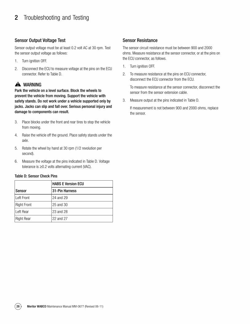
Sensor Output Voltage Test
Sensor output voltage must be at least 0.2 volt AC at 30 rpm. Test the sensor output voltage as follows:
1. Turn ignition OFF.
2. Disconnect the ECU to measure voltage at the pins on the ECU connector. Refer to Table D.
WARNINGPark the vehicle on a level surface. Block the wheels to prevent the vehicle from moving. Support the vehicle with safety stands. Do not work under a vehicle supported only by jacks. Jacks can slip and fall over. Serious personal injury and damage to components can result.
3. Place blocks under the front and rear tires to stop the vehicle from moving.
4. Raise the vehicle off the ground. Place safety stands under the axle.
5. Rotate the wheel by hand at 30 rpm (1/2 revolution per second).
6. Measure the voltage at the pins indicated in Table D. Voltage tolerance is ≥0.2 volts alternating current (VAC).
Table D: Sensor Check Pins
Sensor Resistance
The sensor circuit resistance must be between 900 and 2000 ohms. Measure resistance at the sensor connector, or at the pins on the ECU connector, as follows.
1. Turn ignition OFF.
2. To measure resistance at the pins on ECU connector, disconnect the ECU connector from the ECU.
To measure resistance at the sensor connector, disconnect the sensor from the sensor extension cable.
3. Measure output at the pins indicated in Table D.
If measurement is not between 900 and 2000 ohms, replace the sensor.
Sensor
HABS E Version ECU
31-Pin Harness
Left Front 24 and 29
Right Front 25 and 30
Left Rear 23 and 28
Right Rear 22 and 27
3 Component Replacement
27Meritor WABCO Maintenance Manual MM-0677 (Revised 06-11)
3 Component ReplacementComponent Removal and Installation
Sensors
Sensor Lube Specification
Meritor WABCO specifications call for a sensor lubricant with the following characteristics.
Lube must be mineral oil-based and contain molydisulfide. It should have excellent anti-corrosion and adhesion characteristics and be capable of continuous function in a temperature range of –40° to 300°F (–40° to 150°C).
Meritor WABCO provides sensor lube in a packet with each sensor service part.
Wheel Speed Sensor Replacement — Front Axle
Removal
WARNINGTo prevent serious eye injury, always wear safe eye protection when you perform vehicle maintenance or service.
Park the vehicle on a level surface. Block the wheels to prevent the vehicle from moving. Support the vehicle with safety stands. Do not work under a vehicle supported only by jacks. Jacks can slip and fall over. Serious personal injury and damage to components can result.
CAUTIONTo avoid damage to the electrical system or HABS components, when welding on a HABS-equipped vehicle disconnect the power connector from the ECU.
1. Park the vehicle on a level surface. Apply the parking brakes. Block the rear tires to prevent the vehicle from moving.
If necessary, raise the front tires off the ground. Place safety stands under the axle.
2. Disconnect the fasteners that hold the sensor cable to other components.
3. Disconnect the sensor cable from the chassis harness.
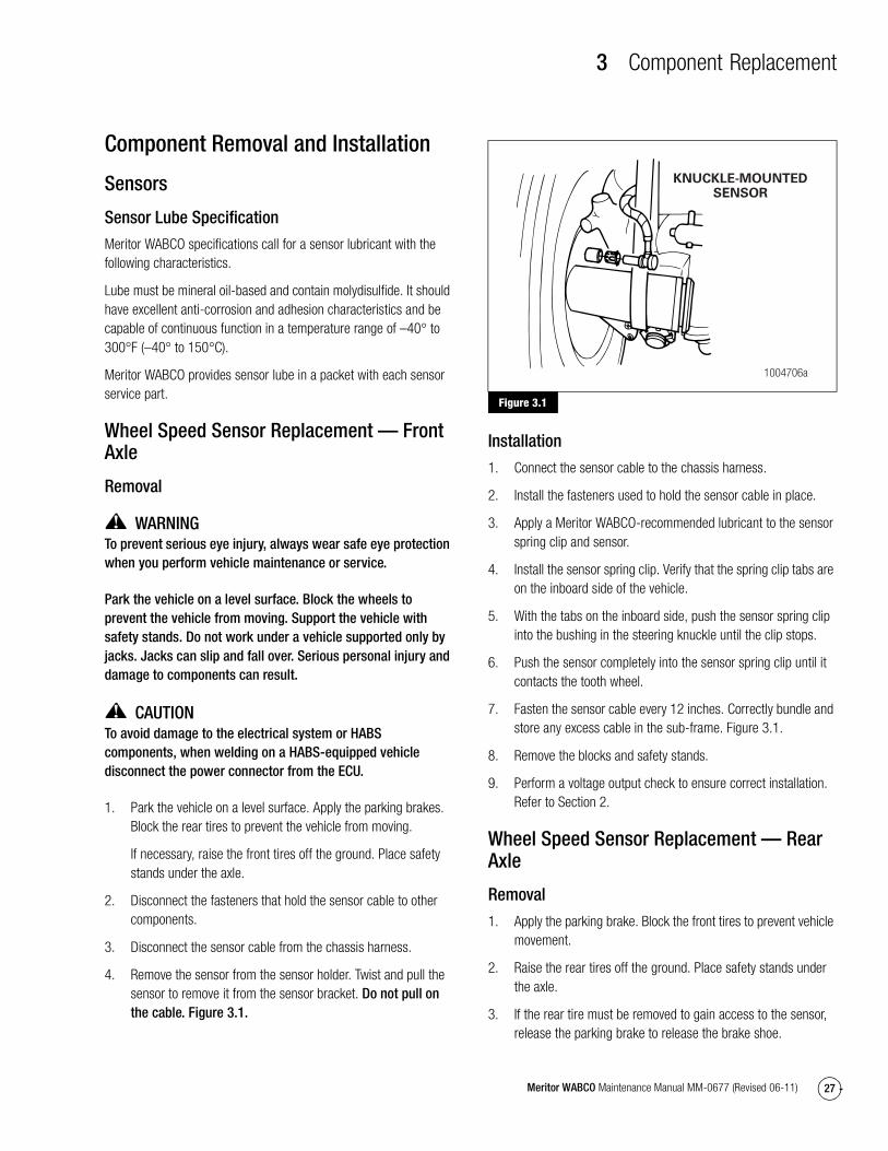
4. Remove the sensor from the sensor holder. Twist and pull the sensor to remove it from the sensor bracket. Do not pull on the cable. Figure 3.1.
Figure 3.1
Installation
1. Connect the sensor cable to the chassis harness.
2. Install the fasteners used to hold the sensor cable in place.
3. Apply a Meritor WABCO-recommended lubricant to the sensor spring clip and sensor.
4. Install the sensor spring clip. Verify that the spring clip tabs are on the inboard side of the vehicle.
5. With the tabs on the inboard side, push the sensor spring clip into the bushing in the steering knuckle until the clip stops.
6. Push the sensor completely into the sensor spring clip until it contacts the tooth wheel.
7. Fasten the sensor cable every 12 inches. Correctly bundle and store any excess cable in the sub-frame. Figure 3.1.
8. Remove the blocks and safety stands.
9. Perform a voltage output check to ensure correct installation. Refer to Section 2.
Wheel Speed Sensor Replacement — Rear Axle
Removal
1. Apply the parking brake. Block the front tires to prevent vehicle movement.
2. Raise the rear tires off the ground. Place safety stands under the axle.
3. If the rear tire must be removed to gain access to the sensor, release the parking brake to release the brake shoe.
Figure 3.1
KNUCKLE-MOUNTEDSENSOR
1004706a
3 Component Replacement
28 Meritor WABCO Maintenance Manual MM-0677 (Revised 06-11)
Remove the wheel and tire assembly from the axle.
4. Remove the sensor from the mounting block. Use a twisting motion if necessary. Do not pull on the cable.
5. Disconnect the sensor cable from the chassis harness.
6. Remove the sensor cable from any cable clamps or clips.
7. Remove the sensor spring clip from the sensor bracket.
Installation
1. Connect the new sensor cable to the chassis harness.
2. Press the sensor spring clip into the sensor bracket, located on the rear axle, until it stops. Verify that the tabs are on the inboard side.
3. Apply a Meritor WABCO-recommended lubricant to the sensor.
4. Push the sensor completely into the spring clip until it contacts the tooth wheel.
5. Reattach the sensor cable to the cable clamps or clips.
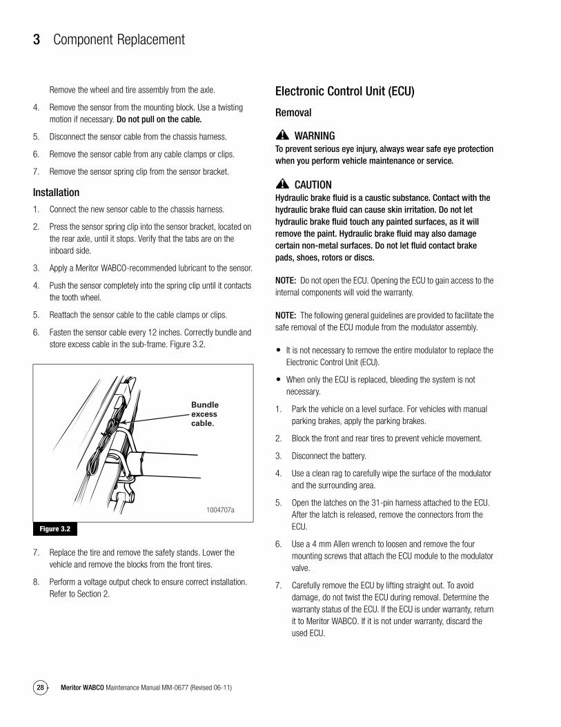
6. Fasten the sensor cable every 12 inches. Correctly bundle and store excess cable in the sub-frame. Figure 3.2.
Figure 3.2
7. Replace the tire and remove the safety stands. Lower the vehicle and remove the blocks from the front tires.
8. Perform a voltage output check to ensure correct installation. Refer to Section 2.
Electronic Control Unit (ECU)
Removal
WARNINGTo prevent serious eye injury, always wear safe eye protection when you perform vehicle maintenance or service.
CAUTIONHydraulic brake fluid is a caustic substance. Contact with the hydraulic brake fluid can cause skin irritation. Do not let hydraulic brake fluid touch any painted surfaces, as it will remove the paint. Hydraulic brake fluid may also damage certain non-metal surfaces. Do not let fluid contact brake pads, shoes, rotors or discs.
NOTE: Do not open the ECU. Opening the ECU to gain access to the internal components will void the warranty.
NOTE: The following general guidelines are provided to facilitate the safe removal of the ECU module from the modulator assembly.
� It is not necessary to remove the entire modulator to replace the Electronic Control Unit (ECU).
� When only the ECU is replaced, bleeding the system is not necessary.
1. Park the vehicle on a level surface. For vehicles with manual parking brakes, apply the parking brakes.
2. Block the front and rear tires to prevent vehicle movement.
3. Disconnect the battery.
4. Use a clean rag to carefully wipe the surface of the modulator and the surrounding area.
5. Open the latches on the 31-pin harness attached to the ECU. After the latch is released, remove the connectors from the ECU.
6. Use a 4 mm Allen wrench to loosen and remove the four mounting screws that attach the ECU module to the modulator valve.
7. Carefully remove the ECU by lifting straight out. To avoid damage, do not twist the ECU during removal. Determine the warranty status of the ECU. If the ECU is under warranty, return it to Meritor WABCO. If it is not under warranty, discard the used ECU.
Figure 3.2
Bundleexcesscable.
1004707a
3 Component Replacement
29Meritor WABCO Maintenance Manual MM-0677 (Revised 06-11)
8. Use a clean rag to carefully clean the area around the valves formerly covered by the ECU.
Installation
CAUTIONExcessive force in positioning the ECU onto the modulator will damage the ECU housing. Do not force the ECU into position. Use a gentle, even pressure when positioning the ECU.
1. Position the ECU onto the modulator valve. Apply gentle pressure to seat the ECU. Motor connectors must achieve full depth into the housing. The gap between the modulator and ECU must not exceed 0.08-inch (2 mm).
2. Use a 4 mm Allen wrench to tighten the four mounting screws that attach the ECU to the modulator. Tighten to 14 in-lb (1.5 N�m). Do not exceed this torque. The metal sleeves on the ECU housing must rest flat on the body of the modulator. @
3. When the ECU is correctly installed with the metal sleeves flat on the modulator, tighten the bolts to 21-30 in-lb (2.5-3.5 N�m). @
WARNINGElectrical connectors must be correctly installed with the latch pushed in to lock the connector. Failure to do so may allow the connectors to come loose or disconnect resulting in loss of ABS function.
4. Attach the 31-pin harness connector to the ECU.
5. Connect the battery.
Modulator Assembly
Removal
CAUTIONThe modulator assembly contains hydraulic brake fluid, a caustic substance. Remove the valve carefully so that fluid does not leak and cause skin irritation or damage to components.
NOTE: If there is interference, the entire bracket and valve assembly can be removed.
1. Apply the parking brakes. Block the front and rear tires to prevent vehicle movement.
2. Place a container under the modulator assembly to catch leaking brake fluid.
3. Disconnect the electrical harness connectors from the modulator assembly.
4. Mark the six brake lines for ease of installation. Disconnect the lines from the modulator assembly.
5. Remove the three mounting capscrews and washers that attach the modulator assembly to the bracket.
NOTE: Whenever any hydraulic system fitting is loosened or disconnected, the entire system must be bled to remove any air that may have entered. Refer to “Brake Bleeding Procedures” in this section.
6. Remove the modulator assembly.
Installation
NOTE: Meritor WABCO recommends that the motor axis makes an angle between +5° and +30° with the horizontal plane, with the motor end pointing up. Contact the OEM or Meritor WABCO for additional information regarding modulator orientation.
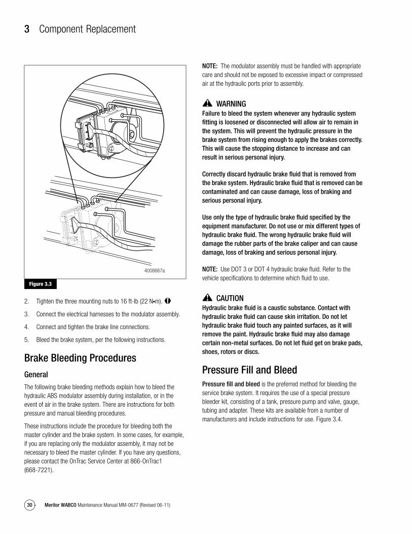
1. Position the modulator assembly in place on the vehicle. Figure 3.3.
3 Component Replacement
30 Meritor WABCO Maintenance Manual MM-0677 (Revised 06-11)
Figure 3.3
2. Tighten the three mounting nuts to 16 ft-lb (22 N�m). @
3. Connect the electrical harnesses to the modulator assembly.
4. Connect and tighten the brake line connections.
5. Bleed the brake system, per the following instructions.
Brake Bleeding ProceduresGeneral
The following brake bleeding methods explain how to bleed the hydraulic ABS modulator assembly during installation, or in the event of air in the brake system. There are instructions for both pressure and manual bleeding procedures.
These instructions include the procedure for bleeding both the master cylinder and the brake system. In some cases, for example, if you are replacing only the modulator assembly, it may not be necessary to bleed the master cylinder. If you have any questions, please contact the OnTrac Service Center at 866-OnTrac1 (668-7221).
NOTE: The modulator assembly must be handled with appropriate care and should not be exposed to excessive impact or compressed air at the hydraulic ports prior to assembly.
WARNINGFailure to bleed the system whenever any hydraulic system fitting is loosened or disconnected will allow air to remain in the system. This will prevent the hydraulic pressure in the brake system from rising enough to apply the brakes correctly. This will cause the stopping distance to increase and can result in serious personal injury.
Correctly discard hydraulic brake fluid that is removed from the brake system. Hydraulic brake fluid that is removed can be contaminated and can cause damage, loss of braking and serious personal injury.
Use only the type of hydraulic brake fluid specified by the equipment manufacturer. Do not use or mix different types of hydraulic brake fluid. The wrong hydraulic brake fluid will damage the rubber parts of the brake caliper and can cause damage, loss of braking and serious personal injury.
NOTE: Use DOT 3 or DOT 4 hydraulic brake fluid. Refer to the vehicle specifications to determine which fluid to use.
CAUTIONHydraulic brake fluid is a caustic substance. Contact with hydraulic brake fluid can cause skin irritation. Do not let hydraulic brake fluid touch any painted surfaces, as it will remove the paint. Hydraulic brake fluid may also damage certain non-metal surfaces. Do not let fluid get on brake pads, shoes, rotors or discs.
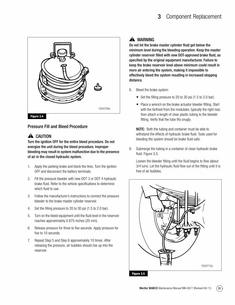
Pressure Fill and BleedPressure fill and bleed is the preferred method for bleeding the service brake system. It requires the use of a special pressure bleeder kit, consisting of a tank, pressure pump and valve, gauge, tubing and adapter. These kits are available from a number of manufacturers and include instructions for use. Figure 3.4.
Figure 3.3
4008667a
3 Component Replacement
31Meritor WABCO Maintenance Manual MM-0677 (Revised 06-11)
Figure 3.4
Pressure Fill and Bleed Procedure
CAUTIONTurn the ignition OFF for the entire bleed procedure. Do not energize the unit during the bleed procedure. Improper bleeding may result in system malfunction due to the presence of air in the closed hydraulic system.
1. Apply the parking brake and block the tires. Turn the ignition OFF and disconnect the battery terminals.
2. Fill the pressure bleeder with new DOT 3 or DOT 4 hydraulic brake fluid. Refer to the vehicle specifications to determine which fluid to use.
3. Follow the manufacturer’s instructions to connect the pressure bleeder to the brake master cylinder reservoir.
4. Set the filling pressure to 20 to 30 psi (1.5 to 2.0 bar).
5. Turn on the bleed equipment until the fluid level in the reservoir reaches approximately 0.875-inches (20 mm).
6. Release pressure for three to five seconds. Apply pressure for five to 10 seconds.
7. Repeat Step 5 and Step 6 approximately 10 times. After releasing the pressure, air bubbles should rise up into the reservoir.
WARNINGDo not let the brake master cylinder fluid get below the minimum level during the bleeding operation. Keep the master cylinder reservoir filled with new DOT-approved brake fluid, as specified by the original equipment manufacturer. Failure to keep the brake reservoir level above minimum could result in more air entering the system, making it impossible to effectively bleed the system resulting in increased stopping distance.
8. Bleed the brake system:
� Set the filling pressure to 20 to 30 psi (1.5 to 2.0 bar).
� Place a wrench on the brake actuator bleeder fitting. Start with the farthest from the modulator, typically the right rear, then attach a length of clear plastic tubing to the bleeder fitting. Verify that the tube fits snugly.
NOTE: Both the tubing and container must be able to withstand the effects of hydraulic brake fluid. Tools used for bleeding the system should be brake fluid-safe.
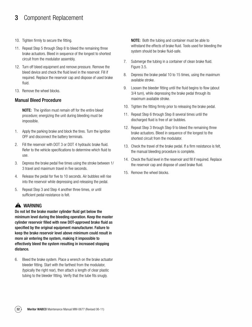
9. Submerge the tubing in a container of clean hydraulic brake fluid. Figure 3.5.
Loosen the bleeder fitting until the fluid begins to flow (about 3/4 turn). Let the hydraulic fluid flow out of the fitting until it is free of air bubbles.
Figure 3.5
Figure 3.4
1004709a
Figure 3.5
1004710a
3 Component Replacement
32 Meritor WABCO Maintenance Manual MM-0677 (Revised 06-11)
10. Tighten firmly to secure the fitting.
11. Repeat Step 5 through Step 8 to bleed the remaining three brake actuators. Bleed in sequence of the longest to shortest circuit from the modulator assembly.
12. Turn off bleed equipment and remove pressure. Remove the bleed device and check the fluid level in the reservoir. Fill if required. Replace the reservoir cap and dispose of used brake fluid.
13. Remove the wheel blocks.
Manual Bleed Procedure
NOTE: The ignition must remain off for the entire bleed procedure; energizing the unit during bleeding must be impossible.
1. Apply the parking brake and block the tires. Turn the ignition OFF and disconnect the battery terminals.
2. Fill the reservoir with DOT 3 or DOT 4 hydraulic brake fluid. Refer to the vehicle specifications to determine which fluid to use.
3. Depress the brake pedal five times using the stroke between 1/3 travel and maximum travel in five seconds.
4. Release the pedal for five to 10 seconds. Air bubbles will rise into the reservoir while depressing and releasing the pedal.
5. Repeat Step 3 and Step 4 another three times, or until sufficient pedal resistance is felt.
WARNINGDo not let the brake master cylinder fluid get below the minimum level during the bleeding operation. Keep the master cylinder reservoir filled with new DOT-approved brake fluid as specified by the original equipment manufacturer. Failure to keep the brake reservoir level above minimum could result in more air entering the system, making it impossible to effectively bleed the system resulting in increased stopping distance.
6. Bleed the brake system. Place a wrench on the brake actuator bleeder fitting. Start with the farthest from the modulator, (typically the right rear), then attach a length of clear plastic tubing to the bleeder fitting. Verify that the tube fits snugly.
NOTE: Both the tubing and container must be able to withstand the effects of brake fluid. Tools used for bleeding the system should be brake fluid-safe.
7. Submerge the tubing in a container of clean brake fluid. Figure 3.5.
8. Depress the brake pedal 10 to 15 times, using the maximum available stroke.
9. Loosen the bleeder fitting until the fluid begins to flow (about 3/4 turn), while depressing the brake pedal through its maximum available stroke.
10. Tighten the fitting firmly prior to releasing the brake pedal.
11. Repeat Step 6 through Step 8 several times until the discharged fluid is free of air bubbles.
12. Repeat Step 3 through Step 9 to bleed the remaining three brake actuators. Bleed in sequence of the longest to the shortest circuit from the modulator.
13. Check the travel of the brake pedal. If a firm resistance is felt, the manual bleeding procedure is complete.
14. Check the fluid level in the reservoir and fill if required. Replace the reservoir cap and dispose of used brake fluid.
15. Remove the wheel blocks.

Meritor WABCO Vehicle Control Systems2135 West Maple Road Printed in USATroy, MI 48084-7121866-OnTrac1 (668-7221) Copyright 2011 Revised 06-11meritorwabco.com Meritor, Inc. Maintenance Manual MM-0677 (16579)