Embed Size (px)
Citation preview
ICE-POP and the NASA Global Precipitation Measurement (GPM) Mission
Walt PetersenGPM Deputy Project Scientist, GV
NASA Marshall Space Flight Center
M. Schwaller (NASA GSFC), V. Chandrasekar (Colo. State Univ.),
Manuel Vega (NASA GSFC)
KMA ICE-POP Meeting
8-11 November 2016
https://ntrs.nasa.gov/search.jsp?R=20160013407 2020-04-04T04:16:16+00:00Z

Broader Framework for NASA ICE-POP Involvement
• Physical and direct validation of Global Precipitation
Measurement (GPM) Mission satellite remote sensing
retrievals in orographic snow
• NuWRF short range forecasts in complex terrain
• Test/improve cloud model representation of snow
microphysics and application to satellite remote sensing
• NASA Short Term Prediction and Operational Research
Transition (SPoRT)- field product testing, utility
• Development of satellite-based ocean latent heat fluxes and
potential impacts for nowcasting and NWP

GPM: “Flagship” Core Observatory
Carries two instruments that can view precipitation (rain, snow, ice) in new ways; serves as a standard to calibrate measurements made from partner satellites
GPM Microwave Imager (GMI):
10-183 GHz13 channels that provides an integrated
picture of energy emitted and scattered by
precipitation
Dual-frequency Precipitation
Radar (DPR): Ku-Ka bandsTwo different radars with different
frequencies that look at precipitation in 3-D
throughout the atmospheric column

4NASA-NOAA Mtg Aug 2016 Page
GPM Observations – Provide a Global View

5
GPM Detects and Estimates Falling Snow Rates
March 17, 2014 Jan 26, 2015
Feb 21, 2015Feb 17, 2015

GPM Ground Validation
• Fundamentally, GPM must produce accurate precipitation estimates over a
broad range of warm and cold season conditions- difficult proposition!
Warm season
RainCold season
Snow/ice
Ground ValidationDirect, Physical, and Integrated Approaches
Goal: Convergence between space and ground-based measurments

Winter storm with mix of
liquid, freezing, frozen
precipitation
GPROF and D3R
delineate snow and
rain..So, we can detect it
GPM’s Level 1 Requirement: Detect snow!
But not always uniformly-
Vision: Unambiguously
capture physical
variability and reliably
estimate liquid equivalent
rates over all terrain
types

NASA GPM Objectives
GPM Ground Validation (ICE-POP Field Campaign - RDP)
• Direct/physical validation of satellite-based snowfall retrieval algorithms
(radar, radiometer, merged satellite algorithms) over coastline and mountains;
melting layer interaction with terrain also of interest.
• Physics of snow, coupling to SWER and satellite remote sensor retrieval
algorithm assumptions
• Model + Observational analyses: Movement toward level IV products
leverage intensive and multi-faceted NWP component.
• Support current PMM/GPM collaboration with KMA- leverage significant
international observational science/data effort.
• Cloud/precipitation model processes (liquid, mixed phase and frozen) testing
and improvement in orographic natural laboratory and under satellite
coverage. Builds model testing database for further remote sensing algorithm
development

Specific Measurement Interests
• Storm Type/Regime: Shallow, deep, synoptic, terrain-forced……
• Physical process and structure responsible for snow in the column
• Snow size distribution
• Snow habit, density, fall speeds, liquid eq. rate, and spatial variability
• Measurement quality and limitations (sensitivity, calibration, viewing
angle…. other artifacts…..)
• Determining and developing a ground “reference” for liquid equivalent
snow rate measurement

NASA Instruments for ICE-POP: D3R, PIP, Pluvio, MRR
Precipitation Imaging Package (PIP) x 2
Dual Frequency Dual Polarimetric Doppler Radar (D3R)
Pluvio2 x 3
Parsivel disdrometer (APU) x 3
MRR x 2

AWS
NASA: 3 Pluvio 400 + APU (Fall 16), 2 PIP, 2 MRR (Fall 17)
PyeongChang Area: Instrument layout
+ APU
+ APU
+ APU

Lookup tables of DFR to estimate Do
Use with ZKu to estimate Nw with m = fixed (ambiguities in assumed r and m).
Integrate to get contents.
CMB additionally uses the GMI scattering to constrain total column IWP (at say, 166 GHz).
Dual-Frequency Approach tested with GV data
Courtesy, V. N. Bringi
Some separation of snow “type”
Deff, vs. DFR…a bit of spread by type
Retrieving snowfall from DPR
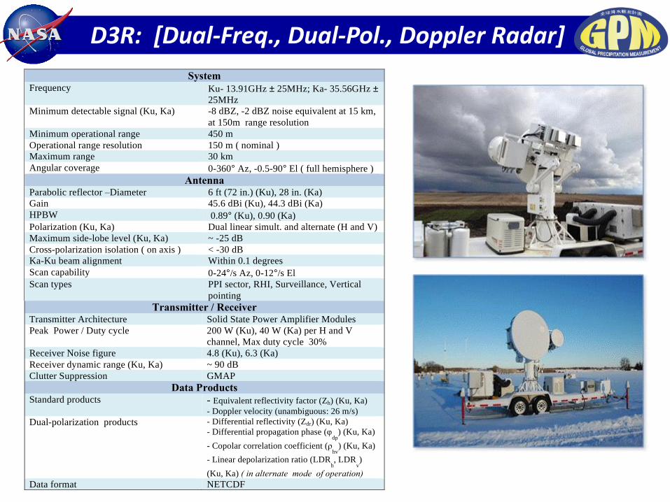
D3R: [Dual-Freq., Dual-Pol., Doppler Radar]Specifications of the Dual-frequency, Dual-polarized, Doppler Radar (D3R)
Transmitter / Receiver Transmitter Architecture Solid State Power Amplifier Modules
Peak Power / Duty cycle 200 W (Ku), 40 W (Ka) per H and V
channel, Max duty cycle 30%
Receiver Noise figure 4.8 (Ku), 6.3 (Ka)
Receiver dynamic range (Ku, Ka) ~ 90 dB
Clutter Suppression GMAP
Data Products Standard products - Equivalent reflectivity factor (Zh) (Ku, Ka)
- Doppler velocity (unambiguous: 26 m/s)
Dual-polarization products - Differential reflectivity (Zdr) (Ku, Ka)
- Differential propagation phase (φdp
) (Ku, Ka)
- Copolar correlation coefficient (ρhv
) (Ku, Ka)
- Linear depolarization ratio (LDRh, LDR
v)
(Ku, Ka) ( in alternate mode of operation)
Data format NETCDF
System Frequency Ku- 13.91GHz ± 25MHz; Ka- 35.56GHz ±
25MHz
Minimum detectable signal (Ku, Ka)
-8 dBZ, -2 dBZ noise equivalent at 15 km,
at 150m range resolution
Minimum operational range 450 m
Operational range resolution 150 m ( nominal )
Maximum range 30 km
Angular coverage 0-360° Az, -0.5-90° El ( full hemisphere )
Antenna Parabolic reflector –Diameter 6 ft (72 in.) (Ku), 28 in. (Ka)
Gain 45.6 dBi (Ku), 44.3 dBi (Ka)
HPBW 0.89° (Ku), 0.90 (Ka)
Polarization (Ku, Ka) Dual linear simult. and alternate (H and V)
Maximum side-lobe level (Ku, Ka) ~ -25 dB
Cross-polarization isolation ( on axis ) < -30 dB
Ka-Ku beam alignment Within 0.1 degrees
Scan capability 0-24°/s Az, 0-12°/s El
Scan types PPI sector, RHI, Surveillance, Vertical
pointing

Kniefel et al., 2015 JGR
Tynella and Chandrasekar (2014, JGR)
DFR (Ku/Ka, Ka,W)
Pol (CDR, ZDR)
DFR(X/Ka, Ka/W)
Snow Physics with Multi-Frequency Polarimetric Radar

D3R February 26, 2015 Snow in Virginia
Growth of large aggregates and some mixed phase
13:00 UTC RHIs

ICE-POP GPM GV Summary
GPM Physical Validation of Retrievals (databases, forward models etc.)
• Direct/physical validation of satellite-based snowfall retrieval algorithms over
complex terrain; melting layer interaction with terrain also of interest.
• Physics of snow, retrieval algorithm assumptions and cloud model
parameterizations of ice processes
• Model + Observational analyses: Movement toward level IV products
leverage intensive and multi-faceted NWP component.
• Support current PMM/GPM collaboration with KMA- leverage significant
international observational science/data effort.
GPM GV Deployment
• D3R Radar IOP 2018
• Supporting snow measurement instruments including PIP, MRR2,
Parsivel, Pluvio (partial winter 2016, remainder IOP 2018)

EXTRA

Summary D3R Deployment Requirements (Current Configuration)
• Power: 208-240 V, 60 Hz, 50A (D3R does have a propane generator, requires LP gas for setup and backup operations during short power loss (2-4 hours))
• Cell communications for remote instrument monitoring, control, display (or wire/fiber hook-up), just one fixed IP address required
• On board servers/processing/storage (RAID), graphical user interface setup in remote operator location through internet connection to instrument
– Antennas and transceiver + IF electronics boxes shipped separately from trailer
– Towing vehicle required for transport and local set up
– Forklift required to assemble antennas and transceiver + IF electronics boxes
– Typically ready to operate within 1-2 days
High Level Assembly Procedure