Embed Size (px)
Citation preview
2168-6777 (c) 2017 IEEE. Personal use is permitted, but republication/redistribution requires IEEE permission. See http://www.ieee.org/publications_standards/publications/rights/index.html for more information.
This article has been accepted for publication in a future issue of this journal, but has not been fully edited. Content may change prior to final publication. Citation information: DOI 10.1109/JESTPE.2017.2735964, IEEE Journal
of Emerging and Selected Topics in Power Electronics
IEEE JOURNAL OF EMERGING AND SELECTED TOPIC IN POWER ELECTRONICS, MARCH 2017 1
Analysis, Design and Maximum Power Efficiency
Tracking for Undersea Wireless Power TransferTaofeek Orekan, Member, IEEE, Peng Zhang, Senior Member, IEEE, and Cyuansi Shih
Abstract—In this paper, a detailed analysis that yields in-depthinsight into the design of undersea wireless power transfer systemis presented. Based on the analytical results, a methodology foroptimized coil design to increase the power transfer efficiency ispresented. Owing to the constant motion experienced by underseawireless power transfer system, a necessary feature is the abilityto operate at a multitude of distances without the need for manualtuning to maintain high efficiency. To address this, we propose anovel Maximum Power Efficiency Tracking (MPET) method thatuses k-Nearest Neighbors (kNN) to estimate the system’s couplingcoefficient and tracks the peak efficiency (> 85%) through anadaptive converter control. Simulation and experimental testresults validate the effectiveness and robustness of MPET inachieving maximum wireless power transfer efficiency under adynamic and uncertain undersea environment.
Index Terms—Maximum power efficiency tracking (MPET),undersea wireless power transfer, k-nearest neighbor, DC-DCconverter, smart ocean system.
I. INTRODUCTION
W Ireless power transfer (WPT) has been revitalized
largely because of the fast expanding market of mobile
devices and electric vehicles [1], [2], [3], [4]. Recently, WPT is
found to be critically needed in distributed ocean systems that
consume excessive power [5], such as an autonomous under-
water vehicle (AUV), underwater sensing nodes, ocean moni-
toring devices, etc. The traditional way of recharging/replacing
these devices manually is time-consuming, resulting in limited
operation range and disrupted services.
One potential solution is to build underwater docking sta-
tion with electrical connectors [6], [7], [8], which, however,
suffers from high maintenance costs and limits to near shore
applications. Here, WPT is investigated as a potent solution
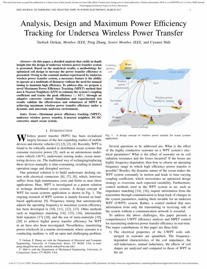
to recharge distributed ocean systems. A design concept of
WPT for ocean systems application is shown in Fig. 1. The
ongoing research of WPT systems is mainly focused on land-
based applications [9]. Frequency tuning that automatically
adjusts the operating frequency to maximize system efficiency
has been developed in [10], [11], [12], [13]. Other methods
such as impedance matching [14], [15], [16], intermediate
field repeaters [17] [18], and the use of meta-materials [19],
[20] to achieve higher power transfer efficiency for WPT
in air have also been investigated. Nevertheless, transferring
power wirelessly in a marine environment, where seawater is a
conducting medium, is still an open and challenging problem.
T. Orekan, P. Zhang are with the Department of Electrical and ComputerEngineering, University of Connecticut, Storrs, CT 06269, USA (e-mail:[email protected], [email protected])
C. Shih is with the Department of Mechanical Engineering, University ofConnecticut, Storrs, CT 06269, USA.
Ocean surface
Ocean floor
Wave
energy
converter
Moored
sensor
Sensor package
AUV
Wireless power
transfer to sensorsSecondary
coil
Contains
primary
coil
Wireless
power
transmission
Fig. 1. A design concept of wireless power transfer for ocean systemsapplication.
Several questions to be addressed are: What is the effect
of the highly conductive seawater on a WPT system’s elec-
trical parameters? What is the effect of seawater on its coil
radiation resistance and the losses incurred? If the losses are
highly frequency-dependent, then how to choose an operating
frequency range in which high efficiency power transfer is
possible? Besides, the dynamic nature of the ocean makes the
WPT system constantly in motion and leads to time-varying
coupling coefficient, which necessitates an optimized design
strategy to overcome such expected variability. Furthermore,
control methods used in the WPT system in air, such as
impedance matching [14], [16], require information from the
transmitter through communication to keep track of changes in
the system parameters, making them inviable for an undersea
WPT (UWPT) system. Rather, a control method that uses
information from only the transmitting or receiving side of
the system without a communication network is essential.
To address the above challenges, this paper presents a
comprehensive UWPT efficiency analysis and MPET control
for maximizing undersea power transfer efficiency in real-time.
The major contributions of this paper are three-fold.
1) The electrical properties of the UWPT coils sub-
merged in seawater are quantified. The frequency-
dependent characteristics of the coil impedance, the
self-inductances, mutual inductance, the effects of coil
shapes are analyzed and compared to those of WPT in
the air.
2168-6777 (c) 2017 IEEE. Personal use is permitted, but republication/redistribution requires IEEE permission. See http://www.ieee.org/publications_standards/publications/rights/index.html for more information.
This article has been accepted for publication in a future issue of this journal, but has not been fully edited. Content may change prior to final publication. Citation information: DOI 10.1109/JESTPE.2017.2735964, IEEE Journal
of Emerging and Selected Topics in Power Electronics
IEEE JOURNAL OF EMERGING AND SELECTED TOPIC IN POWER ELECTRONICS, MARCH 2017 2
2) A methodology for optimized coil design to increase
power transfer efficiency is developed based on the
above analytical results.
3) A novel Maximum Power Efficiency Tracking (MPET)
control method is introduced for achieving a maximum
power efficiency without communication or feedback
from the transmitting side of the UWPT system. In
particular, a k-nearest-neighbors-based machine learning
approach is devised for a real-time estimation of the
coupling coefficient from the receiving side, and the
output voltage is directly controlled using a DC-DC
converter to track maximum power transfer efficiency.
The estimated coupling coefficient is compared to refer-
ence coupling coefficient, and the robustness of the MPET
controller is verified through simulations. Also, this work
constitutes an extended version of our conference paper in [5].
II. UWPT SYSTEM OVERVIEW
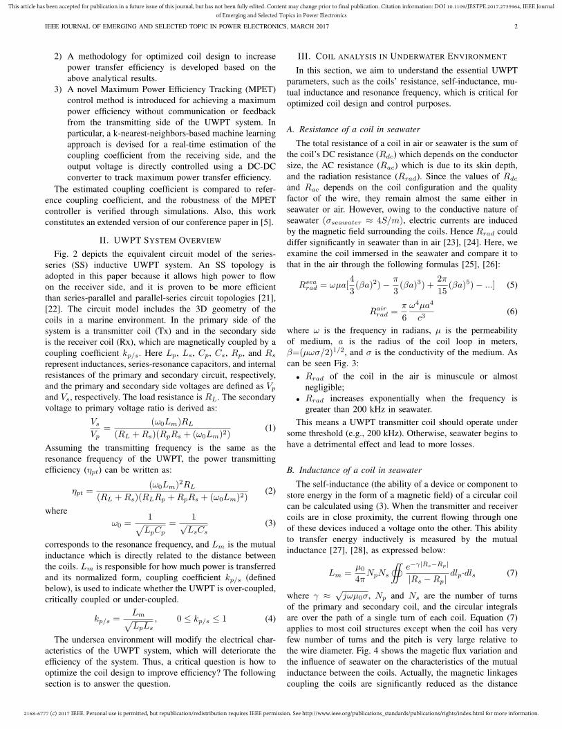
Fig. 2 depicts the equivalent circuit model of the series-
series (SS) inductive UWPT system. An SS topology is
adopted in this paper because it allows high power to flow
on the receiver side, and it is proven to be more efficient
than series-parallel and parallel-series circuit topologies [21],
[22]. The circuit model includes the 3D geometry of the
coils in a marine environment. In the primary side of the
system is a transmitter coil (Tx) and in the secondary side
is the receiver coil (Rx), which are magnetically coupled by a
coupling coefficient kp/s. Here Lp, Ls, Cp, Cs, Rp, and Rs
represent inductances, series-resonance capacitors, and internal
resistances of the primary and secondary circuit, respectively,
and the primary and secondary side voltages are defined as Vp
and Vs, respectively. The load resistance is RL. The secondary
voltage to primary voltage ratio is derived as:
Vs
Vp=
(ω0Lm)RL
(RL +Rs)(RpRs + (ω0Lm)2)(1)
Assuming the transmitting frequency is the same as the
resonance frequency of the UWPT, the power transmitting
efficiency (ηpt) can be written as:
ηpt =(ω0Lm)2RL
(RL +Rs)(RLRp +RpRs + (ω0Lm)2)(2)
where
ω0 =1
√
LpCp
=1√LsCs
(3)
corresponds to the resonance frequency, and Lm is the mutual
inductance which is directly related to the distance between
the coils. Lm is responsible for how much power is transferred
and its normalized form, coupling coefficient kp/s (defined
below), is used to indicate whether the UWPT is over-coupled,
critically coupled or under-coupled.
kp/s =Lm
√
LpLs
, 0 ≤ kp/s ≤ 1 (4)
The undersea environment will modify the electrical char-
acteristics of the UWPT system, which will deteriorate the
efficiency of the system. Thus, a critical question is how to
optimize the coil design to improve efficiency? The following
section is to answer the question.
III. COIL ANALYSIS IN UNDERWATER ENVIRONMENT
In this section, we aim to understand the essential UWPT
parameters, such as the coils’ resistance, self-inductance, mu-
tual inductance and resonance frequency, which is critical for
optimized coil design and control purposes.
A. Resistance of a coil in seawater
The total resistance of a coil in air or seawater is the sum of
the coil’s DC resistance (Rdc) which depends on the conductor
size, the AC resistance (Rac) which is due to its skin depth,
and the radiation resistance (Rrad). Since the values of Rdc
and Rac depends on the coil configuration and the quality
factor of the wire, they remain almost the same either in
seawater or air. However, owing to the conductive nature of
seawater (σseawater ≈ 4S/m), electric currents are induced
by the magnetic field surrounding the coils. Hence Rrad could
differ significantly in seawater than in air [23], [24]. Here, we
examine the coil immersed in the seawater and compare it to
that in the air through the following formulas [25], [26]:
Rsearad = ωµa[
4
3(βa)2)− π
3(βa)3) +
2π
15(βa)5)− ...] (5)
Rairrad =
π
6
ω4µa4
c3(6)
where ω is the frequency in radians, µ is the permeability
of medium, a is the radius of the coil loop in meters,
β=(µωσ/2)1/2, and σ is the conductivity of the medium. As
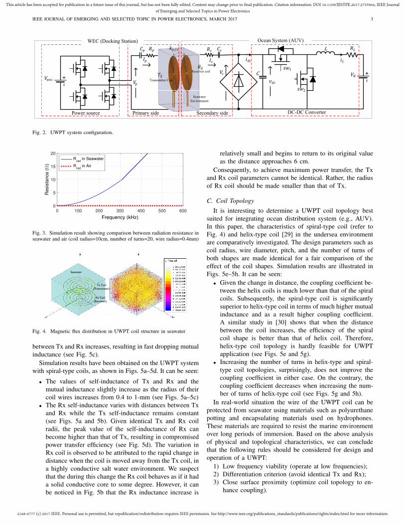
can be seen Fig. 3:
• Rrad of the coil in the air is minuscule or almost
negligible;
• Rrad increases exponentially when the frequency is
greater than 200 kHz in seawater.
This means a UWPT transmitter coil should operate under
some threshold (e.g., 200 kHz). Otherwise, seawater begins to
have a detrimental effect and lead to more losses.
B. Inductance of a coil in seawater
The self-inductance (the ability of a device or component to
store energy in the form of a magnetic field) of a circular coil
can be calculated using (3). When the transmitter and receiver
coils are in close proximity, the current flowing through one
of these devices induced a voltage onto the other. This ability
to transfer energy inductively is measured by the mutual
inductance [27], [28], as expressed below:
Lm =µ0
4πNpNs
‹
e−γ|Rs−Rp|
|Rs −Rp|dlp·dls (7)
where γ ≈ √jωµ0σ, Np and Ns are the number of turns
of the primary and secondary coil, and the circular integrals
are over the path of a single turn of each coil. Equation (7)
applies to most coil structures except when the coil has very
few number of turns and the pitch is very large relative to
the wire diameter. Fig. 4 shows the magetic flux variation and
the influence of seawater on the characteristics of the mutual
inductance between the coils. Actually, the magnetic linkages
coupling the coils are significantly reduced as the distance
2168-6777 (c) 2017 IEEE. Personal use is permitted, but republication/redistribution requires IEEE permission. See http://www.ieee.org/publications_standards/publications/rights/index.html for more information.
This article has been accepted for publication in a future issue of this journal, but has not been fully edited. Content may change prior to final publication. Citation information: DOI 10.1109/JESTPE.2017.2735964, IEEE Journal
of Emerging and Selected Topics in Power Electronics
IEEE JOURNAL OF EMERGING AND SELECTED TOPIC IN POWER ELECTRONICS, MARCH 2017 3
CL
1
/Receiver coil
Transmitter Coil
Seawater
Environment
Power source Primary side Secondary side DC-DC Converter
WEC (Docking Station) Ocean System (AUV)
Fig. 2. UWPT system configuration.
0 100 200 300 400 500 600
Frequency (kHz)
0
5
10
15
20
Re
sis
tan
ce
(Ω
)
Rrad
in Seawater
Rrad
in Air
Fig. 3. Simulation result showing comparison between radiation resistance inseawater and air (coil radius=10cm, number of turns=20, wire radius=0.4mm)
Seawater
Tx Coil(Transmitter)
Rx Coil(Receiver)
Fig. 4. Magnetic flux distribution in UWPT coil structure in seawater
between Tx and Rx increases, resulting in fast dropping mutual
inductance (see Fig. 5c).
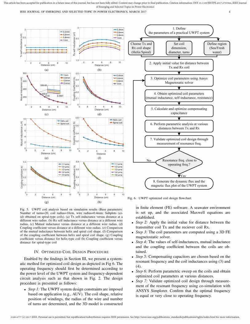
Simulation results have been obtained on the UWPT system
with spiral-type coils, as shown in Figs. 5a–5d. It can be seen:
• The values of self-inductance of Tx and Rx and the
mutual inductance slightly increase as the radius of their
coil wires increases from 0.4 to 1-mm (see Figs. 5a–5c)
• The Rx self-inductance varies with distances between Tx
and Rx while the Tx self-inductance remains constant
(see Figs. 5a and 5b). Given identical Tx and Rx coil
radii, the peak value of the self-inductance of Rx can
become higher than that of Tx, resulting in compromised
power transfer efficiency (see Fig. 5d). The variation in
Rx coil is observed to be attributed to the rapid change in
distance when the coil is moved away from the Tx coil, in
a highly conductive salt water environment. We suspect
that the during this change the Rx coil behaves as if it had
a solid conductive core to some degree. However, it can
be noticed in Fig. 5b that the Rx inductance increase is
relatively small and begins to return to its original value
as the distance approaches 6 cm.
Consequently, to achieve maximum power transfer, the Tx
and Rx coil parameters cannot be identical. Rather, the radius
of Rx coil should be made smaller than that of Tx.
C. Coil Topology
It is interesting to determine a UWPT coil topology best
suited for integrating ocean distribution system (e.g., AUV).
In this paper, the characteristics of spiral-type coil (refer to
Fig. 4) and helix-type coil [29] in the undersea environment
are comparatively investigated. The design parameters such as
coil radius, wire diameter, pitch, and the number of turns of
both shapes are made identical for a fair comparison of the
effect of the coil shapes. Simulation results are illustrated in
Figs. 5e–5h. It can be seen:
• Given the change in distance, the coupling coefficient be-
tween the helix coils is much lower than that of the spiral
coils. Subsequently, the spiral-type coil is significantly
superior to helix-type coil in terms of much higher mutual
inductance and as a result higher coupling coefficient.
A similar study in [30] shows that when the distance
between the coil increases, the efficiency of the spiral
coil shape is better than that of helix coil. Therefore,
helix-type coil topology is hardly feasible for UWPT
application (see Figs. 5e and 5g).
• Increasing the number of turns in helix-type and spiral-
type coil topologies, surprisingly, does not improve the
coupling coefficient in either case. On the contrary, the
coupling coefficient decreases when increasing the num-
ber of turns of helix-type coil (see Figs. 5g and 5h).
In real-world situation the wire of the UWPT coil can be
protected from seawater using materials such as polyurethane
potting and encapsulating materials used on hydrophones.
These materials are required to resist the marine environment
over long periods of immersion. Based on the above analysis
of physical and topological characteristics, we can conclude
that the following rules should be considered for design and
operation of a UWPT:
1) Low frequency viability (operate at low frequencies);
2) Differentiation criterion (avoid identical Tx and Rx);
3) Close surface proximity (optimize coil topology to en-
hance coupling).
2168-6777 (c) 2017 IEEE. Personal use is permitted, but republication/redistribution requires IEEE permission. See http://www.ieee.org/publications_standards/publications/rights/index.html for more information.
This article has been accepted for publication in a future issue of this journal, but has not been fully edited. Content may change prior to final publication. Citation information: DOI 10.1109/JESTPE.2017.2735964, IEEE Journal
of Emerging and Selected Topics in Power Electronics
IEEE JOURNAL OF EMERGING AND SELECTED TOPIC IN POWER ELECTRONICS, MARCH 2017 4
2 4 6 8 10Distance (cm)
1
1.5
2
2.5
3
Tx s
elf inducta
nce (
uH
)
0.4mm
0.6mm
0.8mm
1mm
(a)
2 4 6 8 10
Distance (cm)
1.5
2
2.5
3
Rx s
elf inducta
nce (
uH
)
0.4mm
0.6mm
0.8mm
1mm
(b)
2 4 6 8 10
Distance (cm)
0
200
400
600
800
Mutu
al in
ducta
nce (
nH
)
1mm
0.8mm
0.6mm
0.4mm
3.33 3.3301339.6
339.65
(c)
0 2 4 6 8 10
Distance (cm)
0
0.1
0.2
0.3
0.4
0.5C
ouplin
g C
oeffic
ient (k
)0.4mm
0.6mm
0.8mm
1mm
(d)
0 2 4 6 8 10
Distance (cm)
0
2
4
6
8
10
Mu
tua
l in
du
cta
nce
(µ
H) Helix coil
Spiral coil
(e)
0 2 4 6 8 10
Distance
0
0.2
0.4
0.6
0.8
Co
up
ling
co
eff
icie
nt
(k)
Helix coil
Spiral coil
(f)
0 2 4 6 8 10
Distance (cm)
0
0.1
0.2
0.3
0.4
Co
up
ling
co
eff
icie
nt
(k)
11 turns
12 turns
13 turns
14 turns
15 turns
(g)
0 2 4 6 8 10
Distance (cm)
0
0.2
0.4
0.6
0.8
Co
up
ling
co
eff
icie
nt
(k)
11 turns
12 turns
13 turns
14 turns
15 turns
(h)
Fig. 5. UWPT coil analysis based on simulation results (Base parameters:Number of turns=20, coil radius=10cm, wire radius=0.4mm; Subplots (a)-(d) obtained on spiral-type coils). (a) Tx self-inductance versus distance at adifferent wire radius. (b) Rx self inductance versus distance at a different wireradius. (c) Mutual inductance versus distance at a different wire radius. (d)Coupling coefficient versus distance at a different wire radius. (e) Comparisonof the mutual inductance between helix and spiral coil shape. (f) Comparisonof the coupling coefficient between helix and spiral coil shape. (g) Couplingcoefficient versus distance for helix-type coil (h) Coupling coefficient versusdistance for spiral-type coil
IV. OPTIMIZED COIL DESIGN PROCEDURE
Enabled by the findings in Section III, we present a system-
atic method for optimized coil design as depicted in Fig 6. The
operating frequency should first be determined according to
the power level of the UWPT system and frequency-dependent
circuit analysis such as that shown in Fig. 2. The design
procedure is presented as follows:
• Step 1: The UWPT system design constraints are imposed
based on application (e.g., AUV). The coil shape, relative
position of windings, the radius of the wire and number
of turns are determined, and the 3D model is constructed
Choose Tx and
Rx coil shape
(Helix/Spiral)
Set coil
dimension,
diameter, turns
Define region
(Sea/Fresh
water)
2. Apply initial value for distance between
Tx and Rx coil
3. Optimize coil parameters using Ansys
Magnetosatic solver
Resonance freq. close to
operating freq.?
5. Calculate and optimize compensating
capacitance
6. Perform parametric analysis at various
distances between Tx and Rx
4. Obtain optimized coil parameters
(mutual inductance, self-inductance, resistance)
7. Validate optimized coil design through
measurement of resonance freq.
8. Generate the dynamic flux and the
magnetic flux plot of the UWPT system
1. Define
the parameters of a practical UWPT system
No
Yes
Fig. 6. UWPT optimized coil design flowchart.
in finite element (FE) software. A seawater environment
is set up, and the associated Maxwell equations are
established.
• Step 2: Apply the initial value for distance between the
transmitter coil Tx and the reciever coil Rx.
• Step 3: The coil parameters are computed using a 3D FE
magnetostatic solver.
• Step 4: The values of self-inductances, mutual inductance
and the coupling coefficient between the coils are ob-
tained.
• Step 5: Compensating capacitors are chosen based on the
resonant frequency and the coil inductances using (3) and
(4).
• Step 6: Perform parametric sweep on the coils and obtain
optimized coil parameters at various distances.
• Step 7: Validate optimized coil design through measure-
ment of the resonant frequency using co-simulation with
ANSYS Simplorer. Confirm that the optimal frequency
is equal or very close to operating frequency.
2168-6777 (c) 2017 IEEE. Personal use is permitted, but republication/redistribution requires IEEE permission. See http://www.ieee.org/publications_standards/publications/rights/index.html for more information.
This article has been accepted for publication in a future issue of this journal, but has not been fully edited. Content may change prior to final publication. Citation information: DOI 10.1109/JESTPE.2017.2735964, IEEE Journal
of Emerging and Selected Topics in Power Electronics
IEEE JOURNAL OF EMERGING AND SELECTED TOPIC IN POWER ELECTRONICS, MARCH 2017 5
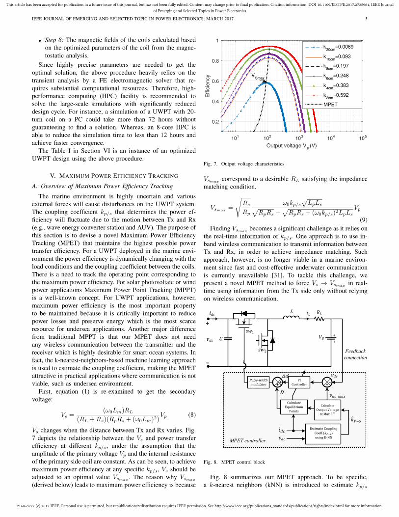
• Step 8: The magnetic fields of the coils calculated based
on the optimized parameters of the coil from the magne-
tostatic analysis.
Since highly precise parameters are needed to get the
optimal solution, the above procedure heavily relies on the
transient analysis by a FE electromagnetic solver that re-
quires substantial computational resources. Therefore, high-
performance computing (HPC) facility is recommended to
solve the large-scale simulations with significantly reduced
design cycle. For instance, a simulation of a UWPT with 20-
turn coil on a PC could take more than 72 hours without
guaranteeing to find a solution. Whereas, an 8-core HPC is
able to reduce the simulation time to less than 12 hours and
achieve faster convergence.
The Table I in Section VI is an instance of an optimized
UWPT design using the above procedure.
V. MAXIMUM POWER EFFICIENCY TRACKING
A. Overview of Maximum Power Efficiency Tracking
The marine environment is highly uncertain and various
external forces will cause disturbances on the UWPT system.
The coupling coefficient kp/s that determines the power ef-
ficiency will fluctuate due to the motion between Tx and Rx
(e.g., wave energy converter station and AUV). The purpose of
this section is to devise a novel Maximum Power Efficiency
Tracking (MPET) that maintains the highest possible power
transfer efficiency. For a UWPT deployed in the marine envi-
ronment the power efficiency is dynamically changing with the
load conditions and the coupling coefficient between the coils.
There is a need to track the operating point corresponding to
the maximum power efficiency. For solar photovoltaic or wind
power applications Maximum Power Point Tracking (MPPT)
is a well-known concept. For UWPT applications, however,
maximum power efficiency is the most important property
to be maintained because it is critically important to reduce
power losses and preserve energy which is the most scarce
resource for undersea applications. Another major difference
from traditional MPPT is that our MPET does not need
any wireless communication between the transmitter and the
receiver which is highly desirable for smart ocean systems. In
fact, the k-nearest-neighbors-based machine learning approach
is used to estimate the coupling coefficient, making the MPET
attractive in practical applications where communication is not
viable, such as undersea environment.
First, equation (1) is re-examined to get the secondary
voltage:
Vs =(ω0Lm)RL
(RL +Rs)(RpRs + (ω0Lm)2)Vp (8)
Vs changes when the distance between Tx and Rx varies. Fig.
7 depicts the relationship between the Vs and power transfer
efficiency at different kp/s, under the assumption that the
amplitude of the primary voltage Vp and the internal resistance
of the primary side coil are constant. As can be seen, to achieve
maximum power efficiency at any specific kp/s, Vs should be
adjusted to an optimal value Vsmax. The reason why Vsmax
(derived below) leads to maximum power efficiency is because
101 102 103 104 105
Output voltage VS
(V)
0.2
0.4
0.6
0.8
1
Eff
icie
ncy
k20cm
=0.0069
k10cm
=0.093
k8cm
=0.197
k6cm
=0.248
k4cm
=0.383
k2cm
=0.592
MPET
VSmax
Fig. 7. Output voltage characteristics
Vsmaxcorrespond to a desirable RL satisfying the impedance
matching condition.
Vsmax=
√
Rs
Rp
ω0kp/s√
LpLs√
RpRs +√
RpRs + (ω0kp/s)2LpLs
Vp
(9)
Finding Vsmaxbecomes a significant challenge as it relies on
the real-time information of kp/s. One approach is to use in-
band wireless communication to transmit information between
Tx and Rx, in order to achieve impedance matching. Such
approach, however, is no longer viable in a marine environ-
ment since fast and cost-effective underwater communication
is currently unavailable [31]. To tackle this challenge, we
present a novel MPET method to force Vs → Vsmaxin real-
time using information from the Tx side only without relying
on wireless communication.
MPET controller
CalculateEquilibriumPoints
PIControllerCalculateOutputVoltageatMaxEff.
‐+
Pulse‐widthmodulator
_
+
‐
CL
Feedback
connection
EstimateCouplingCoeff. usingK‐NN
1
++
d D
Fig. 8. MPET control block
Fig. 8 summarizes our MPET approach. To be specific,
a k-nearest neighbors (kNN) is introduced to estimate kp/s
2168-6777 (c) 2017 IEEE. Personal use is permitted, but republication/redistribution requires IEEE permission. See http://www.ieee.org/publications_standards/publications/rights/index.html for more information.
This article has been accepted for publication in a future issue of this journal, but has not been fully edited. Content may change prior to final publication. Citation information: DOI 10.1109/JESTPE.2017.2735964, IEEE Journal
of Emerging and Selected Topics in Power Electronics
IEEE JOURNAL OF EMERGING AND SELECTED TOPIC IN POWER ELECTRONICS, MARCH 2017 6
using only Rx information (Vs, Is). Subsequently, Vsmaxis
calculated using (9) and serves as the reference for feedback
control to track. As a salient feature, our MPET is an adaptive
tracker that updates the PI controller in real-time, and it
employs a DC-DC converter to achieve the task of changing
output voltage to desire voltage by adjust the duty ratio. This
feature makes the UWPT more resilient to the fast changing
kp/s.
B. Estimation of Coupling Coefficient
The Kirchhoff’s voltage law (KVL) equations for the UWPT
system in Fig. 2 (Tx and Rx side) can be derived as:
Vp = RpIp + ω0kp/sIp√
LpLs
Vs = ω0kp/s√
LpLsIs +RsIs(10)
Thus kp/s can be estimated by
kp/s =Vp ±
√
V 2p − 4RpIs(Vs +RpIs)
2Isω0
√
LpLs
(11)
kp/s is subject to uncertainties on the Tx and Rx sides.
Furthermore, it is infeasible to track both Tx and Rx states in
real-time without communication. To tackle the challenges, we
proposed a data-driven approach, kNN, for robust estimation
of kp/s under uncertainties, through local approximation using
recursive procedure. In particular, kp/s is learned from the
secondary voltages and currents as shown in algorithm 1.
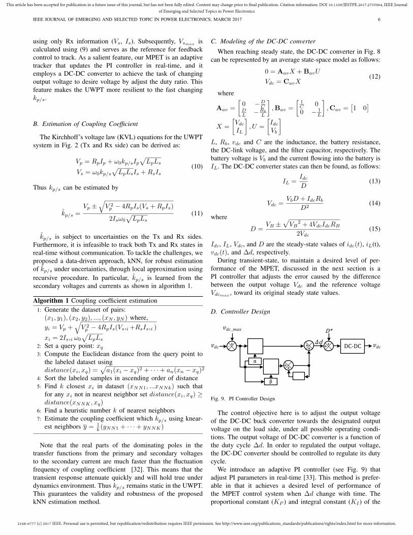
Algorithm 1 Coupling coefficient estimation
1: Generate the dataset of pairs:
(x1, y1), (x2, y2), ..., (xN , yN ) where,
yi = Vp +√
V 2p − 4RpIs(Vs,i +RsIs,i )
xi = 2Is,i ω0
√
LpLs
2: Set a query point: xq
3: Compute the Euclidean distance from the query point to
the labeled dataset using
distance(xi, xq) =√
a1(xi − xq)2 + · · ·+ an(xn − xq)2
4: Sort the labeled samples in ascending order of distance
5: Find k closest xi in dataset (xNN1, ...xNNk) such that
for any xi not in nearest neighbor set distance(xi, xq) ≥distance(xNNK , xq)
6: Find a heuristic number k of nearest neighbors
7: Estimate the coupling coefficient which kp/s using knear-
est neighbors y = 1
k (yNN1 + · · ·+ yNNK)
Note that the real parts of the dominating poles in the
transfer functions from the primary and secondary voltages
to the secondary current are much faster than the fluctuation
frequency of coupling coefficient [32]. This means that the
transient response attenuate quickly and will hold true under
dynamics environment. Thus kp/s remains static in the UWPT.
This guarantees the validity and robustness of the proposed
kNN estimation method.
C. Modeling of the DC-DC converter
When reaching steady state, the DC-DC converter in Fig. 8
can be represented by an average state-space model as follows:
0 = AavX +BavU
Vdc = CavX(12)
where
Aav =
[
0 −DC
DL −Rb
L
]
,Bav =
[
1
C 00 − 1
L
]
,Cav =[
1 0]
X =
[
Vdc
IL
]
, U =
[
IdcVb
]
L, Rb, vdc and C are the inductance, the battery resistance,
the DC-link voltage, and the filter capacitor, respectively. The
battery voltage is Vb and the current flowing into the battery is
IL. The DC-DC converter states can then be found, as follows:
IL =IdcD
(13)
Vdc =VbD + IdcRb
D2(14)
where
D =VB ±
√
VB2 + 4VdcIdcRB
2Vdc(15)
Idc, IL, Vdc, and D are the steady-state values of idc(t), iL(t),
vdc(t), and ∆d, respectively.
During transient-state, to maintain a desired level of per-
formance of the MPET, discussed in the next section is a
PI controller that adjusts the error caused by the difference
between the output voltage Vdc and the reference voltage
Vdcmax, toward its original steady state values.
D. Controller Design
‐ +
_
α
β
++ +
+d D* DC‐DC
1++
Fig. 9. PI Controller Design
The control objective here is to adjust the output voltage
of the DC-DC buck converter towards the designated output
voltage on the load side, under all possible operating condi-
tions. The output voltage of DC-DC converter is a function of
the duty cycle ∆d. In order to regulated the output voltage,
the DC-DC converter should be controlled to regulate its duty
cycle.
We introduce an adaptive PI controller (see Fig. 9) that
adjust PI parameters in real-time [33]. This method is prefer-
able in that it achieves a desired level of performance of
the MPET control system when ∆d change with time. The
proportional constant (KP ) and integral constant (KI ) of the
2168-6777 (c) 2017 IEEE. Personal use is permitted, but republication/redistribution requires IEEE permission. See http://www.ieee.org/publications_standards/publications/rights/index.html for more information.
This article has been accepted for publication in a future issue of this journal, but has not been fully edited. Content may change prior to final publication. Citation information: DOI 10.1109/JESTPE.2017.2735964, IEEE Journal
of Emerging and Selected Topics in Power Electronics
IEEE JOURNAL OF EMERGING AND SELECTED TOPIC IN POWER ELECTRONICS, MARCH 2017 7
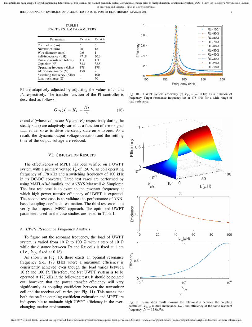
TABLE IUWPT SYSTEM PARAMETERS
Parameters Tx side Rx side
Coil radius (cm) 6 5Number of turns 20 18Wire diameter (mm) 0.6 1Self-inductance (µH) 47 .8 20.3Parasitic resistance (ohms) 1.3 1.3Capacitor (nF) 53.1 38.5Operating frequency (kHz) 178 178AC voltage source (V) 150 –Switching frequency (KHz) – 100Load resistance (Ω) – 50
PI are adaptively adjusted by adjusting the values of α and
β, respectively. The transfer function of the PI controller is
described as follows:
GPI(s) = KP +KI
s(16)
α and β (whose values are KP and KI respectively during the
steady state) are adaptively varied as a function of error signal
verr value, so as to drive the steady state error to zero. As a
result, the dynamic output voltage deviation and the settling
time of the output voltage are reduced.
VI. SIMULATION RESULTS
The effectiveness of MPET has been verified on a UWPT
system with a primary voltage Vp of 150 V, an coil operating
frequency of 178 kHz and a switching frequency of 100 kHz
in its DC-DC converter. Three test cases are performed by
using MATLAB/Simulink and ANSYS Maxwell & Simplorer.
The first test case is to examine the resonant frequency at
which high power transfer efficiency of UWPT is expected.
The second test case is to validate the performance of kNN-
based coupling coefficient estimation. The third test case is to
verify the proposed MPET approach. The optimized UWPT
parameters used in the case studies are listed in Table I.
A. UWPT Resonance Frequency Analysis
To figure out the resonant frequency, the load of UWPT
system is varied from 10 Ω to 100 Ω with a step of 10 Ωwhile the distance between Tx and Rx coils is fixed at 1 cm
( i.e., kp/s fixed at 0.18).
As shown in Fig. 10, there exists an optimal resonance
frequency (i.e., 178 kHz) where a maximum efficiency is
consistently achieved even though the load varies between
10 Ω and 100 Ω. Therefore, the test UWPT system is to be
operated at 178 kHz in the following tests. It should be pointed
out, however, that the power transfer efficiency will vary
significantly as coupling coefficient between the transmitter
coil and the receiver coil varies (see Fig. 11). This means that
both the on-line coupling coefficient estimation and MPET are
indispensable to maintain high UWPT efficiency in the ever-
changing marine environment.
100 150 200 250 300
Frequency (KHz)
0
0.2
0.4
0.6
0.8
1
Effic
iency
RL=100Ω
RL=90Ω
RL=80Ω
RL=70Ω
RL=60Ω
RL=50Ω
RL=40Ω
RL=30Ω
RL=20Ω
RL=10Ω
Fig. 10. UWPT system efficiency (at kP/S = 0.18) as a function offrequency. Target resonance frequency set at 178 kHz for a wide range ofload resistance.
1
- 0 5J .
U
10-1
k p/s
,. -
50
L(µH)
100
(a)
0 20 40 60 80 100L
m(µH)
0
0.5
1
Eff
icie
ncy
10-2
10-1
100
kp/s
0
0.5
1
Eff
icie
ncy
(b)
Fig. 11. Simulation result showing the relationship between the couplingcoefficient kp/s, mutual inductance Lm, and efficiency at the same resonantfrequency f0 = 178kHz.
2168-6777 (c) 2017 IEEE. Personal use is permitted, but republication/redistribution requires IEEE permission. See http://www.ieee.org/publications_standards/publications/rights/index.html for more information.
This article has been accepted for publication in a future issue of this journal, but has not been fully edited. Content may change prior to final publication. Citation information: DOI 10.1109/JESTPE.2017.2735964, IEEE Journal
of Emerging and Selected Topics in Power Electronics
IEEE JOURNAL OF EMERGING AND SELECTED TOPIC IN POWER ELECTRONICS, MARCH 2017 8
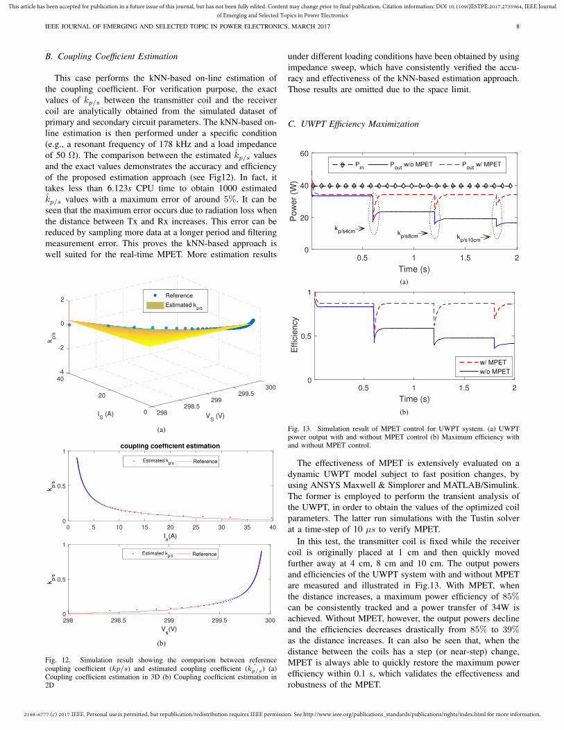
B. Coupling Coefficient Estimation
This case performs the kNN-based on-line estimation of
the coupling coefficient. For verification purpose, the exact
values of kp/s between the transmitter coil and the receiver
coil are analytically obtained from the simulated dataset of
primary and secondary circuit parameters. The kNN-based on-
line estimation is then performed under a specific condition
(e.g., a resonant frequency of 178 kHz and a load impedance
of 50 Ω). The comparison between the estimated kp/s values
and the exact values demonstrates the accuracy and efficiency
of the proposed estimation approach (see Fig12). In fact, it
takes less than 6.123s CPU time to obtain 1000 estimated
kp/s values with a maximum error of around 5%. It can be
seen that the maximum error occurs due to radiation loss when
the distance between Tx and Rx increases. This error can be
reduced by sampling more data at a longer period and filtering
measurement error. This proves the kNN-based approach is
well suited for the real-time MPET. More estimation results
-440
-2
300
kp/s
0
299.5
IS (A)
20
VS (V)
2
299298.5
0 298
Reference
Estimated kp/s
(a)
0 5 10 15 20 25 30 35 40
Is(A)
0
0.5
1
kp/s
coupling coefficient estimation
Estimated kp/s Reference
298 298.5 299 299.5 300
Vs(V)
0
0.5
1
kp/s
Estimated kp/s Reference
(b)
Fig. 12. Simulation result showing the comparison between reference
coupling coefficient (kp/s) and estimated coupling coefficient ( ˆkp/s) (a)Coupling coefficient estimation in 3D (b) Coupling coefficient estimation in2D
under different loading conditions have been obtained by using
impedance sweep, which have consistently verified the accu-
racy and effectiveness of the kNN-based estimation approach.
Those results are omitted due to the space limit.
C. UWPT Efficiency Maximization
0.5 1 1.5 2
Time (s)
0
20
40
60
Po
we
r (W
)
Pin
Pout
w/o MPET Pout
w/ MPET
kp/s8cm
kp/s4cm
kp/s10cm
(a)
0.5 1 1.5 2
Time (s)
0
0.5
1 E
ffic
iency
w/ MPET
w/o MPET
(b)
Fig. 13. Simulation result of MPET control for UWPT system. (a) UWPTpower output with and without MPET control (b) Maximum efficiency withand without MPET control.
The effectiveness of MPET is extensively evaluated on a
dynamic UWPT model subject to fast position changes, by
using ANSYS Maxwell & Simplorer and MATLAB/Simulink.
The former is employed to perform the transient analysis of
the UWPT, in order to obtain the values of the optimized coil
parameters. The latter run simulations with the Tustin solver
at a time-step of 10 µs to verify MPET.
In this test, the transmitter coil is fixed while the receiver
coil is originally placed at 1 cm and then quickly moved
further away at 4 cm, 8 cm and 10 cm. The output powers
and efficiencies of the UWPT system with and without MPET
are measured and illustrated in Fig.13. With MPET, when
the distance increases, a maximum power efficiency of 85%can be consistently tracked and a power transfer of 34W is
achieved. Without MPET, however, the output powers decline
and the efficiencies decreases drastically from 85% to 39%as the distance increases. It can also be seen that, when the
distance between the coils has a step (or near-step) change,
MPET is always able to quickly restore the maximum power
efficiency within 0.1 s, which validates the effectiveness and
robustness of the MPET.

2168-6777 (c) 2017 IEEE. Personal use is permitted, but republication/redistribution requires IEEE permission. See http://www.ieee.org/publications_standards/publications/rights/index.html for more information.
This article has been accepted for publication in a future issue of this journal, but has not been fully edited. Content may change prior to final publication. Citation information: DOI 10.1109/JESTPE.2017.2735964, IEEE Journal
of Emerging and Selected Topics in Power Electronics
IEEE JOURNAL OF EMERGING AND SELECTED TOPIC IN POWER ELECTRONICS, MARCH 2017 9
0 0.5 1 1.5 2
Time (s)
(b)
0.8
0.9
1
Effic
iency
0 0.5 1 1.5 2
(a)
30
35
40P
ow
er
(W)
w/ noise w/o noise
Fig. 14. Simulation result showing the response of MPET when subject toAdditive white Gaussian noise (SNR=6db). (a) UWPT power output with andwithout noise (b) Maximum efficiency with and without noise
To further verify the robustness of MPET, the same test
is performed in a noisy environment when the output voltage
feedback signal and the PI controller are subject to an additive
white Gaussian noise with a signal to noise ratio of 6 db.
Fig.14 shows that MPET remains highly efficient and robust
under such noisy environment.
VII. EXPERIMENTAL VERIFICATION
To verify the analysis above, an experimental UWPT pro-
totype is implemented, as shown in Fig. 15. The experimental
setup consists of a power supply, transmitter and receiver coils,
micro-controller and power electronics converter, and a digital
oscilloscope. The target resonant frequency is set as 178KHz,
and the parameters used in this experiment system are set to
be the same as those in the simulations, except for the input
voltage which is set at 30V due to hardware limitation. All
submerged tests for the experiment are implemented in a 20-
gallon fish tank filled with seawater of 3.63% salt. Hence, these
solutions reasonably models a marine environment. Based on
the coil analysis in Section III, the coils are fabricated in a flat
spiral disk using 22 AWG wire, and their self-inductances are
measured using a complex impedance analyzer. As shown in
Fig. 16, the coils are placed onto a 3D printed disks to hold
them in place. The input and output cables are connected to
the Tx and Rx coil, respectively, and mounted on a test rig
that adjusts the distance between the coils.
On the transmitting side of the UWPT system, a DC source
is used to provide a constant voltage to an operational power
amplifier (APEX PA 94a) at 178KHz generated by a function
generator. The function generator used here could be replaced
by either a standalone function generator IC, or be created
using software on a micro-controller. The DC power supply
Fig. 15. Experimental setup of UWPT.
Fig. 16. UWPT transmitter and receiver test coil
of the power amplifier is set to its maximum range ±30V ,
creating an AC voltage of 30Vpp across the TX coil.
Meanwhile, on the receiving end of the UWPT system,
four SBR10U40CT diodes are used to build a standard full
bridge rectifier which converts the transferred AC voltage
signal to DC. A DC-DC buck converter described in Section
V subsequently used to step-down the voltage to a desired
voltage level. The control unit ATmega328p includes a 10-bit
analog-to-digital converter, which converter the voltage and
current to digitized data used to execute MPET.
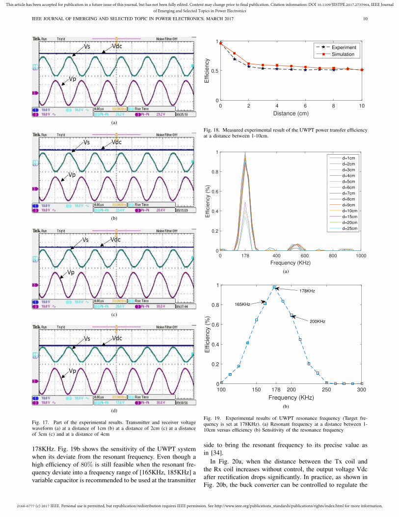
Fig. 17 shows the measured results of the UWPT system;
when the Rx coil is placed at 1cm, 2cm, 3cm, and 4cm away
from the Tx coil. It can be seen that the voltage received
by the RX coil gradually reduces as the distance between
the transmitter and the receiver increases. Fig 17a -17d cor-
responds to power transfer efficiencies of 80%, 73%, 66%,
and 58%, respectively, through seawater. Fig. 18 gives the
measured power efficiency compared against the simulation
results, which shows close agreement between simulations and
experiments.
Fig. 19a shows the resonant frequency obtained by applying
the Fast Fourier Transform (FFT) on the raw data from the
oscilloscope. The result shows the power transfer efficiency is
maximized at the target resonant frequency. As the distance
increases from 1-10cm (target distance range of the UWPT)
the efficiency is still greater than 80%. However, when the
distance increases beyond the target range, the seawater begins
to have detrimental effect on the system and the efficiency
quickly decreases below 50% at the resonant frequency of
2168-6777 (c) 2017 IEEE. Personal use is permitted, but republication/redistribution requires IEEE permission. See http://www.ieee.org/publications_standards/publications/rights/index.html for more information.
This article has been accepted for publication in a future issue of this journal, but has not been fully edited. Content may change prior to final publication. Citation information: DOI 10.1109/JESTPE.2017.2735964, IEEE Journal
of Emerging and Selected Topics in Power Electronics
IEEE JOURNAL OF EMERGING AND SELECTED TOPIC IN POWER ELECTRONICS, MARCH 2017 10
(a)
(b)
(c)
(d)
Fig. 17. Part of the experimental results. Transmitter and receiver voltagewaveform (a) at a distance of 1cm (b) at a distance of 2cm (c) at a distanceof 3cm (c) and at a distance of 4cm
178KHz. Fig. 19b shows the sensitivity of the UWPT system
when its deviate from the resonant frequency. Even though a
high efficiency of 80% is still feasible when the resonant fre-
quency deviate into a frequency range of [165KHz, 185KHz] a
variable capacitor is recommended to be used at the transmitter
0 2 4 6 8 10
Distance (cm)
0
0.5
1
Effic
iency
Experiment
Simulation
Fig. 18. Measured experimental result of the UWPT power transfer efficiencyat a distance between 1-10cm.
0 178 400 600 800 1000
Frequency (KHz)
0
0.2
0.4
0.6
0.8
1
Effic
iency (
%)
d=1cm
d=2cm
d=3cm
d=4cm
d=5cm
d=6cm
d=7cm
d=8cm
d=9cm
d=10cm
d=15cm
d=20cm
d=25cm
(a)
100 150 178 200 250 300
Frequency (KHz)
0
0.2
0.4
0.6
0.8
1
Eff
icie
ncy (
%)
178KHz
165KHz
200KHz
(b)
Fig. 19. Experimental results of UWPT resonance frequency (Target fre-quency is set at 178KHz). (a) Resonant frequency at a distance between 1-10cm versus efficiency (b) Sensitivity of the resonance frequency
side to bring the resonant frequency to its precise value as
in [34].
In Fig. 20a, when the distance between the Tx coil and
the Rx coil increases without control, the output voltage Vdc
after rectification drops significantly. In practice, as shown in
Fig. 20b, the buck converter can be controlled to regulate the

2168-6777 (c) 2017 IEEE. Personal use is permitted, but republication/redistribution requires IEEE permission. See http://www.ieee.org/publications_standards/publications/rights/index.html for more information.
This article has been accepted for publication in a future issue of this journal, but has not been fully edited. Content may change prior to final publication. Citation information: DOI 10.1109/JESTPE.2017.2735964, IEEE Journal
of Emerging and Selected Topics in Power Electronics
IEEE JOURNAL OF EMERGING AND SELECTED TOPIC IN POWER ELECTRONICS, MARCH 2017 11
(a)
(b)
Fig. 20. Experimental results of the UWPT system. (a) Without controlwhen distance is adjusted from 1-10cm at unfixed interval (b) Controlledto a regulated output voltage of 12V.
output voltage at 12V in spite of the changes of the distance
between Tx and Rx.
VIII. CONCLUSION
This paper provides a deep understanding of transferring
power wirelessly in a dynamic undersea environment. Factors
that affect power transfer efficiency are analyzed in detail. A
systematic design approach is developed to optimize the coil
properties and thus improve the overall system efficiency. A
novel Maximum Power Efficiency Tracking (MPET) method
is then developed to estimate UWPT coupling coefficient in
real-time through machine learning and to effectively track
the maximum power efficiency (> 85%) when UWPT is
subject to the motion of the sea. Extensive simulation and
experimental tests have validated the effectiveness of the anal-
ysis, design and MPET approaches. The systematic methods
in this paper have opened a new door of opportunities for
smart ocean systems research. Our future research will be
focused on MPET for multiple source ocean energy systems,
new power electronic topologies that enables load variation
across broader range for better estimation purpose in MPET,
as well as advanced control strategies for MPET.
ACKNOWLEDGMENT
This material is based upon work supported by the National
Science Foundation under Grant No. 1647209 and Eversource
Energy Center under Grant No. 6200980.
The authors gratefully acknowledge the contributions of
Prof. Shengli Zhou for his valuable comments and helpful
suggestions. The authors would also like to thank Alex Sloss-
berg, Frank Ludorf, Walters Justin, and Kyle Buckley for their
assistance in setting up the hardware prototype of the UWPT
system.
REFERENCES
[1] Witricity. [Online]. Available: http://www.witricity.com/[2] Qualcomm/haloipt. [Online]. Available: http://www.qualcomm.com[3] J. M. Miller, O. C. Onar, and M. Chinthavali, “Primary-side power flow
control of wireless power transfer for electric vehicle charging,” IEEE
J. Emerg. Sel. Topics Power Electron., vol. 3, no. 1, pp. 147–162, Mar.2015.
[4] S. Y. R. Hui, W. Zhong, and C. K. Lee, “A critical review of recentprogress in mid-range wireless power transfer,” IEEE Trans. Power
Electrons., vol. 29, no. 9, pp. 4500–4511, Sept. 2014.[5] T. M. Hayslett, T. Orekan, and P. Zhang, “Underwater wireless power
transfer for ocean system applications,” in OCEANS 2016 MTS/IEEE
Monterey, Sept. 2016.[6] R. S. McEwen, B. W. Hobson, and L. McBride, “Docking control system
for a 54-cm-diameter (21-in) auv,” IEEE J. Ocean. Eng., vol. 33, no. 4,pp. 550–562, Oct. 2008.
[7] R. Stokey, B. Allen, and T. Austin, “Enabling technologies for remusdocking: an integral component of an autonomous ocean-samplingnetwork,” IEEE J. Ocean. Eng., vol. 26, no. 4, pp. 487–497, Oct. 2001.
[8] K. Teo, E. An, and P. J. Beaujean, “A robust fuzzy autonomous underwa-ter vehicle (auv) docking approach for unknown current disturbances,”IEEE J. Ocean. Eng., vol. 37, no. 2, pp. 143–155, Apr. 2012.
[9] W. Zhong and S. Y. R. Hui, “Maximum energy efficiency tracking forwireless power transfer systems,” IEEE Trans. Power Electrons., vol. 30,no. 7, pp. 4025–4034, Jul. 2015.
[10] A. P. Sample, D. Meyer, and J. R. Smith, “Analysis, experimental results,and range adaptation of magnetically coupled resonators for wirelesspower transfer,” IEEE Trans. Ind. Electron., vol. 58, no. 2, pp. 544–554, Feb. 2011.
[11] N. Y. Kim, K. Y. Kim, J. Choi, and C. W. Kim, “Adaptive frequency withpower-level tracking system for efficient magnetic resonance wirelesspower transfer,” Electron. Lett., vol. 48, no. 8, pp. 452–454, Apr. 2012.
[12] B. H. Waters, A. P. Sample, P. Bonde, and J. R. Smith, “Powering aventricular assist device (vad) with the free-range resonant electricalenergy delivery (free-d) system,” Proc. IEEE, vol. 100, no. 1, pp. 138–149, Jan. 2012.
[13] Z. Pantic, K. Lee, and S. M. Lukic, “Receivers for multifrequencywireless power transfer: Design for minimum interference,” IEEE J.
Emerg. Sel. Topics Power Electron., vol. 3, no. 1, pp. 234–241, Mar.2015.
[14] J. Park, Y. Tak, Y. Kim, Y. Kim, and S. Nam, “Investigation of adaptiveimpedance matching methods for near-field wireless power transfer,”IEEE Trans. Antennas Propag., vol. 59, no. 5, pp. 1769–1773, MayMay 2011.
[15] L. Huang, A. P. Hu, A. K. Swain, and Y. Su, “Z-impedance compen-sation for wireless power transfer based on electric field,” IEEE Trans.
Power Electron, vol. 31, no. 11, pp. 7556–7563, Nov. 2016.[16] T. C. Beh, T. Imura, M. Kato, and Y. Hori, “Basic study of improving
efficiency of wireless power transfer via magnetic resonance couplingbased on impedance matching,” in IEEE Int. Symp. Ind. Electron, 7 Jul.2010.
[17] F. Zhang, S. A. Hackworth, W. Fu, C. Li, Z. Mao, and M. Sun,“Relay effect of wireless power transfer using strongly coupled magneticresonances,” IEEE Trans. Magn., vol. 47, no. 5, pp. 1478–1481, MayMay 2011.
[18] D. Ahn and S. Hong, “A study on magnetic field repeater in wirelesspower transfer,” IEEE Trans. Ind. Electron., vol. 60, no. 1, pp. 360–371,Jan. 2013.
[19] M. J. Chabalko, J. Besnoff, and D. S. Ricketts, “Magnetic field en-hancement in wireless power with metamaterials and magnetic resonantcouplers,” IEEE Antennas Wireless Propag. Lett., vol. 15, pp. 452–455,Jul. 2015.
[20] E. S. Rodrguez, A. K. RamRakhyani, and D. Schurig, “Compact low-frequency metamaterial design for wireless power transfer efficiencyenhancement,” IEEE Trans. Microw. Theory Tech., vol. 64, no. 5, pp.1644–1654, May 2016.
[21] M. Ishihara, K. Umetani, H. Umegami, E.Hiraki, and M. Yamamoto,“Quasi-duality between ss and sp topologies of basic electric-fieldcoupling wireless power transfer system,” Electron. Lett., vol. 52, no. 25,pp. 2057–2059, Dec. 2016.

2168-6777 (c) 2017 IEEE. Personal use is permitted, but republication/redistribution requires IEEE permission. See http://www.ieee.org/publications_standards/publications/rights/index.html for more information.
This article has been accepted for publication in a future issue of this journal, but has not been fully edited. Content may change prior to final publication. Citation information: DOI 10.1109/JESTPE.2017.2735964, IEEE Journal
of Emerging and Selected Topics in Power Electronics
IEEE JOURNAL OF EMERGING AND SELECTED TOPIC IN POWER ELECTRONICS, MARCH 2017 12
[22] T. Campi, S. Cruciani, F. Maradei, and M. Feliziani, “Near-field reduc-tion in a wireless power transfer system using lcc compensation,” IEEE
Trans. Electromagn. Compat., vol. 59, no. 2, pp. 686–694, Apr. 2017.[23] K. Iizuka, R. King, and C. Harrison, “Self- and mutual admittances of
two identical circular loop antennas in a conducting medium and in air,”IEEE Trans. Antennas Propag., vol. 14, no. 4, pp. 440–450, Jul. 1966.
[24] A. Jenkins, V. Bana, and G. Anderson, “Impedance of a coil in seawater,”in IEEE Antennas Propag. Soc. Int. Symp. (APSURSI), Jul. 2014.
[25] M. B. Kraichman, “Impedance of a circular loop antenna in a infniteconducting medium,” J. Res. Nat. Bur. of Std. Radio Propag., vol. 66D,no. 4, Jul. 1962.
[26] J. R. Wait, “Insulated loop antenna immersed in a conducting medium,”J. Res. Nat. Bur. of Std., vol. 59, no. 2, Aug. 1957.
[27] S. Babic, F. Sirois, C. Akyel, and C. Girardi, “Mutual inductancecalculation between circular filaments arbitrarily positioned in space:Alternative to grover’s formula,” IEEE Trans. Magn., vol. 46, no. 9, pp.3591–3600, Sep. 2010.
[28] C. Zhang, W. Zhong, X. Liu, and S. Y. R. Hui, “A fast method forgenerating time-varying magnetic field patterns of mid-range wirelesspower transfer systems,” IEEE Trans. Power Electrons., vol. 30, no. 3,pp. 1513–1520, Mar. 2015.
[29] P. Hadadtehrani, P. Kamalinejad, R. Molavi, and S. Mirabbasi, “On theuse of conical helix inductors in wireless power transfer systems,” inIEEE Canadian Conf. Elect. Comp. Eng. (CCECE), May 2016.
[30] X. Shi, C. Qi, M. Qu, S. Ye, G. Wang, L. Sun, and Z. Yu, “Effects ofcoil shapes on wireless power transfer via magnetic resonance coupling,”Journal of Electromagnetic Waves and Applications, vol. 28, no. 11, pp.1316–1324, 2014.
[31] Z. Zeng, S. Fu, H. Zhang, Y. Dong, and J. Cheng, “A survey ofunderwater optical wireless communications,” IEEE Commun. Surveys
Tuts., vol. 19, no. 1, pp. 204–238, Aug. Firstquarter 2017.[32] V. Jiwariyavej, T. Imura, and Y. Hori, “Coupling coefficients estimation
of wireless power transfer system via magnetic resonance coupling usinginformation from either side of the system,” IEEE J. Emerg. Sel. Topics
Power Electron., vol. 3, no. 1, pp. 191–200, Mar. 2015.[33] V. Arikatla, “Adaptive control methods for dc-dc switching power
converters,” Ph.D. dissertation, Univ. of Alabama, 2011.[34] J. Tian and A. P. Hui, “A dc-voltage-controlled variable capacitor for
stabilizing the zvs frequency of a resonant converter for wireless powertransfer,” IEEE Trans. Power Electrons., vol. 32, no. 3, pp. 2312–2318,Mar. 2017.
Taofeek Orekan (M’14) received the B.S. degreein electrical engineering from Kennesaw State Uni-versity, Atlanta, GA, USA, M.S. degree in electricalengineering from University of Connecticut, Storrs,CT, USA, and currently he is a Ph.D. candidate inelectrical engineering at University of Connecticut.His research interests include control of wirelesspower transfer systems, renewable energy, smartocean systems and smart grid.
Taofeek is a member of CIGRE, IEEE YoungProfessionals, and IEEE-HKN. He was a recipient
of the prestigious NSF GK-12 Fellowship award in 2014 and 2015.
Peng Zhang (M’07−SM’10) received the Ph.D.degree in electrical engineering from the Universityof British Columbia, Vancouver, BC, Canada, in2009. He is the Castleman Professor in EngineeringInnovation, and Associate Professor of ElectricalEngineering at the University of Connecticut, Storrs,USA. He was a System Planning Engineer at BCHydro and Power Authority, Vancouver. His researchinterests include software defined smart grid, micro-grids, smart and connected communities/cities, cybersecurity, and smart ocean systems. Dr. Zhang is a
Registered Professional Engineer in BC, Canada, and an individual memberof CIGRE.
Cyuansi Shih is a PhD candidate in MechanicalEngineering from University of Connecticut. He re-ceived his M.S. degree in Engineering Science fromNational Taiwan University. His research is in thearea of dynamics and control, adaptive cooperativecontrol and bio-mechanics.