Embed Size (px)
Citation preview

UNIVERSITY LINZJOHANNES KEPLER
JKU
Implementation of an Extensible Mapper ofAeronautical Information Exchange Model
Data to ObjectLogic
Master's Thesis
to confer the academic degree of
Master of Science
in the Master's Program
Business Informatics
Author:
Ilko Kova£i¢, BSc.
Submission:
Data & Knowledge Engineering Institute
Thesis Supervisor:
o. Univ.-Prof. DI Dr. Michael Schre�
Assistant Thesis Supervisor:
Felix Burgstaller, MSc.
Linz, July 2015

Eidesstattliche ErklärungIch, Ilko Kovačić, erkläre an Eides statt, dass ich die vorliegende Masterarbeitselbstständig und ohne fremde Hilfe verfasst, andere als die angegebenenQuellen und Hilfsmittel nicht benutzt bzw. die wörtlich oder sinngemäßentnommenen Stellen als solche kenntlich gemacht habe. Die vorliegendeMasterarbeit ist mit dem elektronisch übermittelten Textdokument identisch.
Signed:
Date: July 15, 2015
I

AcknowledgementsMany people supported and encouraged me during my studies and especiallyin the last year. Without them I would not have been able to successfullycomplete my master thesis. Therefore I would like to express my gratefulnessto them in the following paragraphs.
I am grateful to o. Univ.-Prof. DI Dr. Michael Schrefl who gave methe opportunity to be a part of the Semantic NOTAM (SemNOTAM)research project. I express my gratefulness to my assistant thesis supervisorFelix Burgstaller, MSc. for helping me whenever I needed support. MoreoverI would like to thank Dieter Steiner, MSc. who provided me an environmentto implement my work. Furthermore I would like to thank Margit Brandlfor supporting me during the bureaucratic processes.
This thesis would not have been possible without the support of FelixBurgstaller, MSc. who has been an outstanding advisor. Whenever I neededhelp he provided the right hints and useful information. Moreover I wouldlike to thank him for the time he spent with me in the countless meetingswere he gave me guidance in writing and structuring the thesis. EspeciallyI would like to thank him for supporting me after the working hours whichcannot be taken for granted.
Finally I would express my gratefulness to my family and to my friends.I would like to thank my girlfriend Marlene who supported me during mywhole studies and especially during the completion of my master thesis.
II

AbstractThe Air Traffic Management (ATM) covers various tasks regarding air trafficcontrol, air traffic flow management and aeronautical information services.This generates a huge amount of information addressing airspace users. Theinformation exchange is based on the Aeronautical Information ExchangeModel (AIXM) which is designed to enable the management and distributionof complex and evolving Extensible Markup Language (XML) structures. Toavoid an information overflow the Semantic NOTAM (SemNOTAM) projectprovides intelligent and fine-grained filtering of these information. SemNO-TAM is implemented as a rule-based system using ObjectLogic (OL). There-fore, a corresponding OL representation of the information to be filteredis required. This thesis contributes to the SemNOTAM system by imple-menting a mapper which transforms the XML data to its corresponding OLrepresentation following the object-property model. This OL representationis inserted into the SemNOTAM system and used to conduct queries. Arequirements analysis is conducted which analyzes the in- and outputs, ex-ceptions, and constraints on the processing task. Based on the requirementsa mapping approach is developed which especially covers the handling of ge-ographical data. Moreover the XML transformation technologies ExtensibleStylesheet Language Transformation (XSLT), Simple Application Program-ming Interface (API) for XML (SAX), Streaming API for XML (StAX) andDocument Object Model (DOM) are evaluated with regards to their suitabil-ity for the mapper. It is shown that the DOM outperforms other technologiesand consequently the mapper is implemented using DOM and Java.
III

ZusammenfassungDas Flugverkehrsmanagement umfasst verschiedene Aufgaben von derFlugverkehrskontrolle, Flugverkehrsflussmanagement bis hin zur Verwaltungvon aeronautischen Informationsservices. Die dabei generierte enorme In-formationsmenge adressiert die Benutzer des Flugraums. Der Information-saustausch erfolgt anhand des Aeronautical Information Exchange Model(AIXM), welches entwickelt wurde um den Austausch und die Verwaltungvon komplexen Extensible Markup Language (XML) Strukturen, deren En-twicklung noch nicht abgeschlossen ist, zu ermöglichen. Um einen Infor-mationsüberfluss bei den Benutzern zu vermeiden, wurde im Semantic NO-TAM (SemNOTAM) Projekt eine intelligente und feingranulare Filterungdieser Informationen entwickelt. SemNOTAM baut auf einem regel-basiertenSystem auf welches mittels ObjectLogic (OL), einer formalen Sprache zurWissensrepräsentation, realisiert ist. Aus diesem Grund ist auch eine OLRepräsentation der Informationen notwendig. Der Beitrag dieser Arbeitzum SemNOTAM System ist die Implementierung eines Mappers der dieXML Daten in ihre korrespondierende OL Repräsentation überführt. DieOL Repräsentation wird danach in das SemNOTAM System eingefügt unddient damit als Abfragegrundlage. Um dies zu bewerkstelligen, wird eineAnforderungsanalyse durchgeführt, welche die Ein- und Ausgaben, die Aus-nahmen und die Einschränkungen während der Verarbeitung analysiert.Basierend auf den ermittelten Anforderungen wird ein konzeptueller Entwurfentwickelt, welcher insbesondere die Bearbeitung von geographischen Datenumfasst. Des Weiteren wird die Verwendung der XML-Transformations-Technologien Extensible Stylesheet Language Transformation (XSLT), Sim-ple Application Programming Interface (API) for XML (SAX), StreamingAPI for XML (StAX) und Document Object Model (DOM) evaluiert. Eswird gezeigt, dass die DOM Technologie in Anbetracht der Leistungsfähigkeitden anderen überlegen ist, weshalb auch die Implementierung des Mappersmittels DOM und Java erfolgt.
IV

Contents
1 Introduction 11.1 Preface . . . . . . . . . . . . . . . . . . . . . . . . . . . . . . . 11.2 Problem Statement . . . . . . . . . . . . . . . . . . . . . . . . 41.3 Outline . . . . . . . . . . . . . . . . . . . . . . . . . . . . . . . 5
2 SemNOTAM 72.1 SemNOTAM-Project . . . . . . . . . . . . . . . . . . . . . . . 82.2 Notices to Airman . . . . . . . . . . . . . . . . . . . . . . . . 142.3 Aeronautical Information Exchange Model . . . . . . . . . . . 182.4 ObjectLogic . . . . . . . . . . . . . . . . . . . . . . . . . . . . 27
3 Requirements Analysis 343.1 Task Description . . . . . . . . . . . . . . . . . . . . . . . . . 343.2 Requirements . . . . . . . . . . . . . . . . . . . . . . . . . . . 423.3 Challenges and Problems . . . . . . . . . . . . . . . . . . . . . 44
4 Mapping Approach 474.1 Basic Mapping Concept . . . . . . . . . . . . . . . . . . . . . 484.2 Mapping Approach . . . . . . . . . . . . . . . . . . . . . . . . 524.3 Mapping Technologies . . . . . . . . . . . . . . . . . . . . . . 714.4 DOM Extension Capabilities . . . . . . . . . . . . . . . . . . . 84
5 The Mapper 865.1 Conceptual Design . . . . . . . . . . . . . . . . . . . . . . . . 875.2 Implementation . . . . . . . . . . . . . . . . . . . . . . . . . . 92
6 Conclusion 97
Appendix A Class Diagrams A
Appendix B Prototype Source Code E
1

Chapter 1
Introduction
Contents1.1 Preface . . . . . . . . . . . . . . . . . . . . . . . . . 11.2 Problem Statement . . . . . . . . . . . . . . . . . 41.3 Outline . . . . . . . . . . . . . . . . . . . . . . . . . 5
This section gives an introduction to the topic of ATM and the processeswithin it. Furthermore, the scope of the thesis, its contribution, and finallyits structure is provided.
1.1 Preface
The European Organisation for the Safety of Air Navigation (EUROCON-TROL) expects to reach the 2008 peak of traffic (10.1 million flights) withinand from Europe in 2016 (EUROCONTROL, 2014, p. 25). To manage thistraffic volume an efficient and effective ATM is required (EUROCONTROL,2015d). The ATM consists of the following three main components (EURO-CONTROL, 2015d):
1. The Air Traffic Control is the process of safely separating aircraft inorder to prevent collisions or critical situations. Therefore a separationof the aircraft in the sky as they fly and at the airports where they takeoff and land is needed.
1

CHAPTER 1. INTRODUCTION 2
2. Air Traffic Flow Management takes place before the flight andrepresents a central repository where all flights are analysed and com-puted. For each flight a flight plan is computed, determining the exactposition of an aircraft at any given point in time. This flight plan isused by aeronautical controllers to supervise an aircraft and its flightcrew.
3. Aeronautical Information Services (AIS) provide, combine anddistribute aeronautical information to airspace users. The services pro-vide information regarding administrative or legal matters, safety ornavigation related activities, or about technical issues and their up-dates.
The information provided by AIS is encoded within so called Notices toAirmen (NOTAM). NOTAMs are a loosely structured, text-based repre-sentation of aeronautical information which are used by aviation systemsand flight personnel such as flight crews or controllers. Flight crews useNOTAMs, provided by AIS, for their pre-flight briefings (EUROCONTROL,2015c). These pre-flight briefings allow the pilots to get and read therelevant NOTAMs for their flight.
However, flight crews have to face a flood of NOTAMs during theirpre-flight briefings. This flood is a consequence of limited filtering capa-bilities of current Aeronautical Information Management (AIM) systems(EUROCONTROL, 2015b). The loosely structured textual representationof NOTAMs conflicts with the needs of automated systems which requirehighly structured and standardised data structures (EUROCONTROL,2010). The problem is that the decision whether a NOTAM is relevant or notmostly requires human interpretation since geographical, navigational, tem-poral information, and descriptions about events are represented as free text.
To overcome these drawbacks of textual NOTAMs a joint project be-tween EUROCONTROL and the Federal Aviation Administration (FAA)was launched in 2010 (EUROCONTROL & Federal Aviation Administration,2011b). The aim was to replace textual NOTAMs with digital NOTAMs.Digital NOTAMs represent structured data sets which can be read andinterpreted by automated systems. In order to provide an encoding fordigital NOTAMs, the existing Aeronautical Information Exchange Model(AIXM) was used and extended (Geospatial Intelligence TWG, 2006).AIXM allows to represent ATM elements such as event scenarios or featureslike airports, airspaces or routes. The machine-interpretable data structureallows filtering of NOTAMs without the need of human interpretation. Thus
CHAPTER 1. INTRODUCTION 3
the flood of NOTAMs retrieved by flight crews and other flight personnelcan be minimized using this automated filtering capabilities. This reducesthe information overload and stress of the crew which positively affects theirsituation awareness.
Services, such as the Federal NOTAM Service and NOTAM Distribu-tion Service (FNS-NDS), already provide filtering of NOTAMs but on a verylimited scale. The service allows querying basic geographical information,text, and/or attributes for a point in time (Burgstaller et al., 2015).However these query capabilities are not sufficient enough for complexqueries like filtering for a flight plan. To pose such a query, intelligentfiltering capabilities are required.
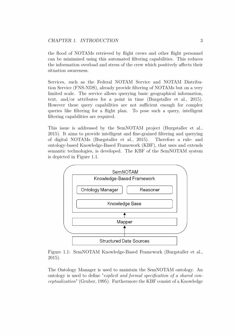
This issue is addressed by the SemNOTAM project (Burgstaller et al.,2015). It aims to provide intelligent and fine-grained filtering and queryingof digital NOTAMs (Burgstaller et al., 2015). Therefore a rule- andontology-based Knowledge-Based Framework (KBF), that uses and extendssemantic technologies, is developed. The KBF of the SemNOTAM systemis depicted in Figure 1.1.
Figure 1.1: SemNOTAM Knowledge-Based Framework (Burgstaller et al.,2015).
The Ontology Manager is used to maintain the SemNOTAM ontology. Anontology is used to define "explicit and formal specification of a shared con-ceptualization" (Gruber, 1995). Furthermore the KBF consist of a Knowledge

CHAPTER 1. INTRODUCTION 4
Base (KB) and a reasoner. The KB contains the explicit facts and includesdeduction rules which are used by the reasoner to derive new facts. Thesederived facts represent the implicit knowledge since it is not available withoutapplying the deduction rules (Gringinger, Eier, & Merkl, 2011).
In order to access this knowledge the KBF provides a semantic queryinginterface (Frequentis AG, 2015). This interface allows to use various crite-ria. These criteria are based on location in space, progress in time, differentevents, aircraft, or flight types or any combination of them. Furthermore,structured data such as digital NOTAMs can be loaded into the KB. How-ever, all data including queries must be mapped to a corresponding knowl-edge representation in order to store it in the SemNOTAM ontology of theKB (Burgstaller et al., 2015). Therefore a mapper is needed, as depictedin Figure 1.1. It maps various structured data sources such as the AIXMrepresentation of digital NOTAMs to the corresponding declarative repre-sentation. This mapper is the main topic of this thesis.
1.2 Problem Statement
This thesis comprises the implementation of the mapper. As depicted inFigure 1.1 the mapper is a central component of the whole SemNOTAMsystem since it operates as an interface between the KBF and the structureddata sources.
However, the implementation of such a mapper is not a trivial taskdue to the various data sources and interfaces. During the mappingprocess no information must be lost and the resulting knowledge-basedrepresentation must be syntactically and semantically correct. In additionto the central mapping task, the mapper must also provide preprocessingcapabilities in order to enrich the accessed data. Since new data sourcescan be introduced in the future, the mapper must provide extensioncapabilities which allow to add new mapping and/or preprocessing taskswithout modifying the existing implementation. The SemNOTAM systemis designed with a focus on high adaptability and flexibility in order toface changing requirements. This design rational has to be followed in theimplementation of the mapper to avoid design breaks.
The mapper transforms the structural data sources to their corre-sponding knowledge-based representation. The resulting knowledge-based

CHAPTER 1. INTRODUCTION 5
representation is loaded into the KB. The mapper allows to configure in-and outputs, handle exceptions, and to conduct various processing tasks.Moreover it completes missing information and provides extension capabili-ties supporting future data sources. Without the mapper it would neither bepossible to define new conceptualizations, insert new facts nor pose queriesagainst the KB as their declarative representation could not be determined.The absence of the capability to insert new knowledge from structured datasources, such as digital NOTAMs, and to conduct specified queries wouldmake the whole SemNOTAM system inoperative. This clearly shows thecontribution of this thesis to the usage and progress of the SemNOTAMKBF.
The implementation of the mapper is based on requirements, whichare derived from the SemNOTAM KBF. The requirements will be used todevelop an mapping approach and to identify suitable technologies. Finally,the implementation will be evaluated in order to determine the performance.
1.3 Outline
The remaining thesis is organized in the following sections: At the beginningthe SemNOTAM architecture and the used data representation is detailed,followed by the requirements analysis and the introduction of a mappingapproach fulfilling them. Afterwards the implementation is presented.Finally, an evaluation of the mapper and a conclusion are provided.
Section 2 introduces and explains basic concepts needed for this the-sis. Therefore the SemNOTAM project is detailed and its architecture isanalysed (Section 2.1). Furthermore, textual NOTAMs is examined (Sec-tion 2.2.1). Thereafter the drawbacks of textual NOTAMs are explained andhow they can be overcome by digital NOTAMs (Section 2.2.2). Finally, theused representations are introduced. This includes the AIXM representation(Section 2.3) for structured data and OL (Section 2.4) for knowledge.
A requirement analysis is conducted in Section 3. Therefore the taskis delineated which covers the examination of the available data sources(Section 3.1). The data source examination comprises NOTAMs (Sec-tion 3.1.1), configuration data (Section 3.1.2), and queries (Section 3.1.3).In Section 3.2 the requirements are extracted, grouped, and detailed basedon the task description. Besides the requirements, Section 3 describeschallenges and problems which can occur during the fulfillment of the

CHAPTER 1. INTRODUCTION 6
requirements (Section 3.3).
In Section 4 the basic mapping concept is introduced (Section 4.1).Moreover, the mapping approach is introduced in order to fulfill all previ-ously defined requirements (Section 4.2). To implement the mapping conceptsuitable technologies are analyzed, evaluated, and the best performing isselected (Section 4.3). Furthermore, the extension capabilities of the selectedtechnology are delineated in Section 4.4.
Based on the mapping concept and the selected technology the mapper isimplemented in Section 5. Therefore, a conceptual design is introducedwhich supports extension and configuration capabilities (Section 5.1). Themapper is implemented based on the selected technology and the conceptualdesign (Section 5.2). Moreover, the performance is evaluated in order toshow how the mapper performs while increasing the workload (Section 5.2.3).
Finally a conclusion is given which summarizes the thesis and provides anoutlook on future work Section 6.

Chapter 2
SemNOTAM
Contents2.1 SemNOTAM-Project . . . . . . . . . . . . . . . . 8
2.1.1 Background . . . . . . . . . . . . . . . . . . . . . . 82.1.2 Problem Description . . . . . . . . . . . . . . . . . 92.1.3 Method . . . . . . . . . . . . . . . . . . . . . . . . 102.1.4 SemNOTAM Architecture . . . . . . . . . . . . . . 12
2.2 Notices to Airman . . . . . . . . . . . . . . . . . . 142.2.1 Textual Notices to Airmen . . . . . . . . . . . . . 152.2.2 Digital Notices to Airmen . . . . . . . . . . . . . . 16
2.3 Aeronautical Information Exchange Model . . . 182.3.1 eXtensible Markup Language . . . . . . . . . . . . 202.3.2 AIXM Conceptual Model and XML Schema . . . . 202.3.3 Temporality Model . . . . . . . . . . . . . . . . . . 232.3.4 Geographic Model . . . . . . . . . . . . . . . . . . 242.3.5 Feature Identification and Reference . . . . . . . . 26
2.4 ObjectLogic . . . . . . . . . . . . . . . . . . . . . . 27
This section will introduce the basic concepts needed for this thesis. There-fore the SemNOTAM project is detailed and especially the current architec-ture of the SemNOTAM system is analysed. A delineation of the system ismandatory in order to identify interfaces which can be used by the mapper.
7

CHAPTER 2. SEMNOTAM 8
Besides describing SemNOTAM, the textual NOTAMs and their successor,the digital NOTAMs, are examined. Moreover, a theoretical background ofthe used representations and technologies, which are crucial for the under-standing the mapping task, are provided.
2.1 SemNOTAM-Project
As mentioned in Section 1.1, the SemNOTAM research project addresses thechallenge of filtering NOTAMs and was launched in 2014 (Schrefl, 2014).It is a cooperative project between industry and university partners. TheAustrian high-tech company Frequentis AG1 is operating in ATM and pub-lic safety and transport branches providing and developing information andcommunication systems (Frequentis AG, 2015). The Institute of Data &Knowledge Engineering of the Department of Business Informatics of the Jo-hannes Kepler University Linz which conducts research in the area of seman-tic systems, business intelligence, business process modelling and integration,and in web-based system (Gringinger, 2014). Other cooperation partners andsubcontractors are EUROCONTROL, AustroControl and the FAA.
2.1.1 Background
The SemNOTAM project relies on previous research done in the EURO-CONTROL’s Single European Sky ATM Research Program (SESAR) andFAA’s Next Generation Air Transportation System (NextGen). As stated in(Gringinger et al., 2011) these two programs aim to modernize and harmonizethe ATM systems locally and globally. They are developing new capabilities,procedures and technologies in order transform the ATM systems. Formerground-based systems, which depend on voice communication betweencontroller and the pilot and radar, are transformed to air/ground-integratedaviation systems based on digital data communication and satellite nav-igation (European Union, 2015). One modernisation is the replacementof textual NOTAMs with digital NOTAMs in the future AIM (Schrefl, 2014).
As stated Section 1.1, flight crews, especially pilots, have to face a flood ofinformation. This can lead to stress, lack of situation awareness, missingprioritization, information overload and misunderstandings (Burgstaller et
1http://www.frequentis.com

CHAPTER 2. SEMNOTAM 9
al., 2015). In addition to the increasing number of NOTAMs this problemcan be also traced back to the mandatory requirement of achieving onehundred percent recall of relevant NOTAMs (Burgstaller et al., 2015). Onehundred percent recall is mandatory because a not retrieved relevant andsafety critical NOTAM can lead to unpredictable negative consequences.As stated in Section 1.1, present services provide filtering of NOTAMs buton a very limited scale. Intelligent filtering capabilities are needed to sup-porting complex queries like filtering for flight plans (Burgstaller et al., 2015).
As shown in (Burgstaller et al., 2015), there are two approaches found inthe literature addressing intelligent NOTAM processing. The first approachof (Gringinger, Trausmuth, Balaban, Jahn, & Milchrahm, 2012) is anontology-based one not supporting business rules. However, without busi-ness rules it is not possible to define how, for whom and when information isrelevant and how the recipients should be notified (Gringinger et al., 2012).In contrast to the approach of (Gringinger et al., 2012), (Zimmer et al.,2011) introduce a rule-based approach, using business rules which determinewhen and which information is significant for whom depending on the flightphases. However this approach does not support reasoning over ontologiesleading to restricted capabilities since derived knowledge is not available orconsidered while filtering (Gringinger et al., 2012).
2.1.2 Problem Description
The SemNOTAM project follows a rule- and ontology-based approachintroducing a knowledge-based framework that uses and extends semantictechnologies enabling intelligent and fine-grained filtering and querying ofdigital NOTAMs (Burgstaller et al., 2015). As already mentioned in Sec-tion 1.1, the project aims to provide a machine-readable and ontology-basedrepresentation of digital NOTAMs which enable semantic querying usinga wide range of criteria (Frequentis AG, 2015). This provides the airmenintelligent support for the management of their NOTAMs (Frequentis AG,2015).
Due to the heterogeneous character of digital NOTAMs regarding theirstructure and semantics, intelligent querying becomes a challenging task.As stated in Section 2.2.1 about NOTAMs, they can be used to describespecific events. Events are defined within event scenarios which describepossible NOTAM conditions while being linked to specific AIXM features(Burgstaller et al., 2015). For each of these events, such as airspace
CHAPTER 2. SEMNOTAM 10
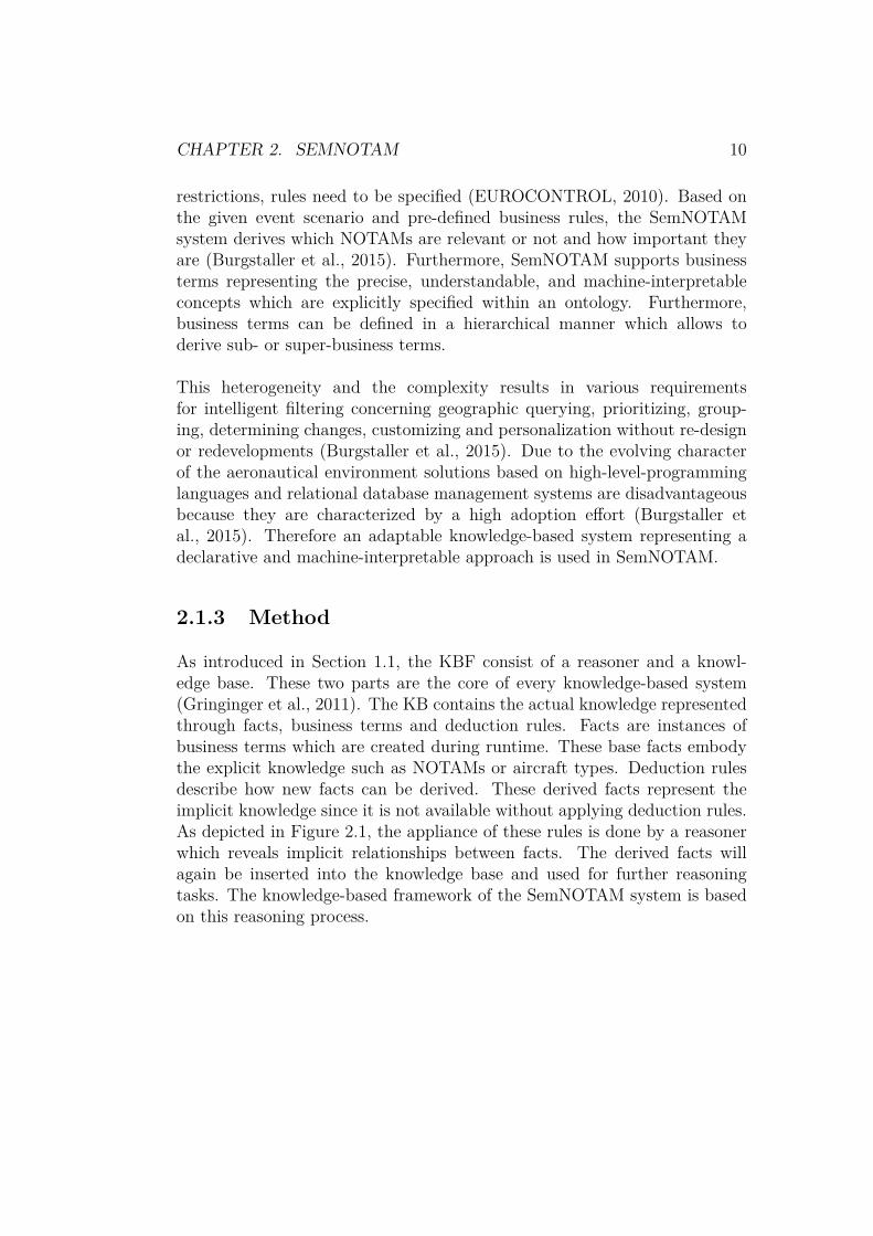
restrictions, rules need to be specified (EUROCONTROL, 2010). Based onthe given event scenario and pre-defined business rules, the SemNOTAMsystem derives which NOTAMs are relevant or not and how important theyare (Burgstaller et al., 2015). Furthermore, SemNOTAM supports businessterms representing the precise, understandable, and machine-interpretableconcepts which are explicitly specified within an ontology. Furthermore,business terms can be defined in a hierarchical manner which allows toderive sub- or super-business terms.
This heterogeneity and the complexity results in various requirementsfor intelligent filtering concerning geographic querying, prioritizing, group-ing, determining changes, customizing and personalization without re-designor redevelopments (Burgstaller et al., 2015). Due to the evolving characterof the aeronautical environment solutions based on high-level-programminglanguages and relational database management systems are disadvantageousbecause they are characterized by a high adoption effort (Burgstaller etal., 2015). Therefore an adaptable knowledge-based system representing adeclarative and machine-interpretable approach is used in SemNOTAM.
2.1.3 Method
As introduced in Section 1.1, the KBF consist of a reasoner and a knowl-edge base. These two parts are the core of every knowledge-based system(Gringinger et al., 2011). The KB contains the actual knowledge representedthrough facts, business terms and deduction rules. Facts are instances ofbusiness terms which are created during runtime. These base facts embodythe explicit knowledge such as NOTAMs or aircraft types. Deduction rulesdescribe how new facts can be derived. These derived facts represent theimplicit knowledge since it is not available without applying deduction rules.As depicted in Figure 2.1, the appliance of these rules is done by a reasonerwhich reveals implicit relationships between facts. The derived facts willagain be inserted into the knowledge base and used for further reasoningtasks. The knowledge-based framework of the SemNOTAM system is basedon this reasoning process.

CHAPTER 2. SEMNOTAM 11
Figure 2.1: Process of reasoning (Gringinger et al., 2011).
As depicted in Figure 2.2 the framework accesses various structured datasources. The AIXM baseline data which is referenced in the digital NOTAMsrepresents static data which can be accessed remotely or locally (EURO-CONTROL & Federal Aviation Administration, 2011b, p. 9). The baselineincludes all values of all properties of a given permanently changed featurestate (EUROCONTROL & Federal Aviation Administration, 2010, p. 7).Furthermore it accesses configuration data like route segments, aircraft char-acteristics and the query which includes specific interests (Burgstaller et al.,2015). All this accessed data must be mapped to the corresponding knowl-edge representation in order to store it in the SemNOTAM ontology of theKB (Burgstaller et al., 2015). As shown in figure 2.2, this AIXM to Ontol-ogy Mapper is one central layer within the SemNOTAM system because itprovides the interface between the structured data and their semantic repre-sentation.
Figure 2.2 shows that the SemNOTAM ontology is located in the KB. Itcontains the base, derived facts and business terms which are specified bythe user or the framework (Burgstaller et al., 2015). Business rules are in-cluded within the SemNOTAM Rules in order to define whether a NOTAMis relevant and how important it is. Beside the SemNOTAM ontology andthe business rules, the KBF provides a SemNOTAM Interest Specification.This allows the user to specify his/her interest and thus defines which Sem-NOTAM Rules will be applied. Their temporal, aircraft and spatial interestare provided as simple interests which can be combined to complex interestsusing the set operators intersection and union.

CHAPTER 2. SEMNOTAM 12
Figure 2.2: SemNOTAM Knowledge-Based Framework (Gringinger et al.,2011).
This KBF introduced in the SemNOTAM system provides high adapting ca-pabilities due to the declarative representation of data and rules (Burgstalleret al., 2015). Furthermore it enables the intelligent and fine-grained filteringbased on specific interests which can take individual interests into account.By supporting business terms, the framework allows to group query resultsaccording to topics (Burgstaller et al., 2015).
2.1.4 SemNOTAM Architecture
The architecture of the SemNOTAM system is based on the core architecturedepicted in Figure 2.2. It supports embedding into environments which canbe connected to external systems. The only prerequisites are a interfaceto a database supporting the system with NOTAMs and a Result Buildercombining the outcome with the original NOTAMs (Burgstaller, Szabolcs,Steiner, & Frequentis AG, 2014, p. 6).
Beside the environment, the SemNOTAM architecture can be split into the

CHAPTER 2. SEMNOTAM 13
Figure 2.3: SemNOTAM architecture and interfaces (Burgstaller et al., 2014,p. 6).
following two parts, as depicted in figure 2.3 (Burgstaller et al., 2014):
• SemNOTAM component: it provides SemNOTAM interfaces to theenvironment. These interfaces grant all access needed to load or purgedata and rules (Knowledge Acquistion), conduct queries (Query Inter-face), provide configuration data such as segments (Segment Interface)and retrieve results (Result Interface) (Burgstaller et al., 2014, p. 11).All of these interfaces use an AIXM respectively XML representationas input data and pass them over to the mapper.
• Core: the core comprises the KBF and the appropriate KBF API(Burgstaller et al., 2014, p. 10). Both parts depend on the ontology-based representation provided in OL. The whole KBF component iswritten in OL and can be access by the API of the OntoBroker Rea-soner of Semafora. Since the SemNOTAM component implements in-terfaces to load and purge NOTAMs the core provides the KBF API tosupport this actions (Burgstaller et al., 2014, p. 10). Furthermore, theKBF API grants loading and purging of segments as well as other con-figuration data such as concepts, aircraft, groups, priority orders, grouparrangements and default parameter (Burgstaller et al., 2014, p. 10).However these NOTAM and knowledge acquisition interfaces requirean OL representation of the configuration data respectively NOTAMsprovided by the mapper. The SemNOTAM interfaces for querying andretrieving the result are also supported by the KBF API. In contrast tothe Query Interface which requires again an OL representation as input,the Result Interface outputs a XML respectively AIXM representation(Burgstaller et al., 2014, p. 10).
As shown the SemNOTAM component depends on an AIXM representa-tion whereas the Core expects an OL representation. Both depend on the

CHAPTER 2. SEMNOTAM 14
AIXM to OL mapper between them because their interfaces access eachother. Based on this detailed architecture, mapping requirements can bederived. However, before this will be done the two representations will beexamined.
2.2 Notices to Airman
NOTAMs represent unclassified notices or advisories that are distributedby means of telecommunication (Myers, 1978). They primarily addressaviation personnel and systems that are essential for flight operations suchas controllers and pilots. NOTAMs contain information regarding anyhazards of a route at a specific location, essential timely knowledge or anychange, establishment, or condition in any aeronautical facility or service.Changes or essential timely knowledge are represented by events. Eventswhich indicate changes in conditions or availability of aeronautical facilitiesor services can lead to possible hazards. Examples for hazards can be closedrunways, military exercises, temporary route changes, dust or volcanic ashcontaminations or changes states of runways due to weather conditions.
From the examples it can be seen that there are many NOTAMs which canbe divided into several types regarding their addressed audience. A coarsedivision is provided by the FAA (Federal Aviation Administration, 2010),where international, domestic, civilian and military NOTAMs are distin-guished. However, there are important specific types such as SNOWTAMs,BIRDTAMs and ASHTAMs (Icao-Ais-Aimsg, 2011). SNOWTAMs are usedas notifications about the removal or existence of unsafe conditions dueto ice, snow, water or slush indicating that the movement area is possiblyrestricted (Icao-Ais-Aimsg, 2011). BIRDTAMs include information aboutpossible bird strike areas and ASHTAMs contain warnings about volcanicactivities such as eruptions and ash clouds (Icao-Ais-Aimsg, 2011).
Even thought NOTAMs can address different audiences and cover var-ious events, they are the most basic and important concept within theATM domain. NOTAMs were already defined in 1978. In the last 50years NOTAMs developed from simple text messages, supplying pilotsand other operational flight personnel with critical safety information, tocontainers for other not safety related information such as Navigational Aids(NAVAIDs) (EUROCONTROL, 2015b). Since NOTAMs require humaninterpretation this extended usage has led to an information overload.

CHAPTER 2. SEMNOTAM 15
Performance statistics of the European Aeronautical Information ServicesDatabase (EAD) show an increase of newly added NOTAMs within Europafrom 44764 in 2007 to 91578 in 2013 (EUROCONTROL, 2015c). Thisincrease represents a doubling of newly added NOTAMs within only sixyears. The analysis of the increased NOTAM circulation in the FranceAIS (International Civil Aviation Organization, 2013), identified severalreasons for this development. They show that the number of NOTAMsis not directly correlated to air traffic; but it depends on the number ofair navigation facilities and activities. The main causes for the extensiveNOTAM usage can be found in the Global Navigation Satellite System(GNSS) navigation, instrument flight procedures, information about runwayclosures or restrictions, taxiways, air navigation warnings, informationabout time slots and restrictions regarding aerodromes and their facilities,services, and airspaces (International Civil Aviation Organization, 2013). Asalready stated in Section 1.1, this flood of NOTAMs is given to flight crewswhich use them for pre-flight briefings resulting in a Pre-flight InformationBulletin (PIB) of ten to fifty pages for an internal European flight (EU-ROCONTROL, 2015c). Due to current limited filtering capabilities fortyand sometimes up to ninety percent of the provided information is neitherimportant nor relevant for their flight (EUROCONTROL, 2015b). This canlead to flight crews unaware of important and safety critical informationsince they are not able to detect it within this flood of information.
2.2.1 Textual Notices to Airmen
NOTAMs cover various events and use cases. This comprises especiallydynamic data such as temporal knowledge. For that reason a textualrepresentation for non-static information was chosen. As mentioned inSection 1.1, this led to textual NOTAMs which were loosely structuredand mainly provided as free text. However this conflicted with automatedAIM systems (EUROCONTROL, 2010). AIM systems highly depend onstructured and standardised data structures representing accurate, timely,and quality assured aeronautical information (EUROCONTROL, 2010).
Since dynamic information is encoded as free text it becomes the bur-den of the pilot or controller to recognize which information is relevant andwhich is obsolete (EUROCONTROL, 2015b). This manual process offersan entry point for errors and requires a post-submission quality control(EUROCONTROL, 2015b). Possible errors can occur due to misinterpre-tations of NOTAMs based on different or missing understanding of used

CHAPTER 2. SEMNOTAM 16
words (EUROCONTROL, 2015b). Besides that, human interpretationis also required for safety critical events which can be partly encoded astext. To cover such events, a detailed description is required which againleads to complexity which cannot be comprehended easily by non-experts.(EUROCONTROL, 2015b). Although human interpretation is error-prone,it is needed to feed automated systems. The encoded information withintextual NOTAMs cannot be extracted otherwise in a satisfying way. Thissignificantly slows down the information flow and, as mentioned before,leads to errors and misunderstandings (EUROCONTROL, 2015b).
The information overload mentioned in Section 2.2.1 is not just a re-sult of the increased number of NOTAMs, it is also a consequence ofthe geographical and temporal inaccuracies of textual NOTAMs (EURO-CONTROL, 2015c). Geographical aeronautical information is expressed bygeometrical forms defining an ATM element such as airport surface, airspace,routes, runways, etc. The automatic interpretation of NOTAMs containinggeographical data is currently limited to the consideration of the positionand the radius of influence (EUROCONTROL, 2015c). These limitationslead to vague geographical definitions where operators tend to overestimatethe radius of influence in order to be on the safe side (EUROCONTROL,2015c). These overestimations negatively affect flight crews as NOTAMswhich are completely irrelevant for them will be assigned to their pre-flightbriefing. As stated before, the temporal aspect is also being consideredin order to find the latest NOTAMs and their states. The interpretationwhether a NOTAM is relevant for a given time period, again depends onthe human interpretation which can result once more in a high number ofirrelevant NOTAMs (EUROCONTROL, 2015c).
2.2.2 Digital Notices to Airmen
To overcome the drawbacks of textual NOTAMs, EUROCONTROL andFAA launched a joint project in 2009 with the aim of developing digitalNOTAMs (EUROCONTROL & Federal Aviation Administration, 2011b, p.2). In contrast to textual NOTAMs, digital NOTAMs are structured datasets which can be read and interpreted by automated systems removing theneed of human interpretation. A digital NOTAM is defined as a "data setmade available through digital services containing information concerningthe establishment, condition or change in any aeronautical facility, service,procedure or hazard, the timely knowledge of which is essential to systemsand automated equipment used by personnel concerned with flight operations"

CHAPTER 2. SEMNOTAM 17
(EUROCONTROL, 2010). Although the focus is set on automated systems,humans will still be addressed by NOTAMs and therefore the informationcan be transformed to a human readable textual and graphical represen-tation (EUROCONTROL & Federal Aviation Administration, 2011b, p.6). Digital NOTAMs do not only comprise a simple conversion to a morestructured format. It is a shift in the paradigm. Temporary or permanentinformation updates will not be encoded within an own data structure.They are integrated within the information of longer duration utilizing thesame data structures and distribution channels (EUROCONTROL, 2015b).
The encoding for digital NOTAMs was developed in cooperation be-tween FAA and EUROCONTROL with the support of the internationalAIS community and the International Civil Aviation Organization (ICAO)(EUROCONTROL, 2010). It is based on the previously Aeronautical Infor-mation Exchange Model (AIXM) version 4.5, which can be used to modelATM elements such as aircraft, runways, etc. (EUROCONTROL & FederalAviation Administration, 2011b). Prior versions of AIXM were already usedby central database of EAD and locally in different States but with limitedmodeling, temporal and geographical capabilities (EUROCONTROL, 2010).A more detailed description of AIXM will be provided in Section 2.3.
Digital NOTAMs will not replace the textual NOTAMs immediately,for many years they will be issued parallel with classical NOTAMs (EU-ROCONTROL & Federal Aviation Administration, 2011b, p. 6). Theimplementation of digital NOTAMs will follow an incremental approach,where the most important and mostly used types of NOTAMs will besupported first (EUROCONTROL & Federal Aviation Administration,2011b, p. 6).
Besides overcoming the drawbacks of textual NOTAMs, digital NO-TAMs will be also used to improve the efficiency and enhance global civilaviation safety (EUROCONTROL, 2015c). The information within digitalNOTAMs can be automatically plotted for visual representation. Temporalaspects such as schedules can be computer interpreted, cross referenceswithin static data are provided and transformations between differentformats and/or textual or graphical output will be supported. Moreover,automatic integration between computer systems will be provided and it willbe possible to conduct complex queries in order to select the most recentNOTAMs which fulfill user-specified criteria (EUROCONTROL, 2010).
Digital NOTAMs will allow automatic checks due to their machine-
CHAPTER 2. SEMNOTAM 18
readable structure. This will improve coherence and correctness andenhance the overall data quality (EUROCONTROL, 2010). Since a graphi-cal data representation is also provided, visual checks by human operatorswill be supported too (EUROCONTROL, 2010). With these checks, missingand wrong data can be easily detected which again contributes to animproved data quality. Besides that, digital NOTAMs will facilitate anaccurate situation awareness based on shared and up-to-date data sets(EUROCONTROL, 2010). Situation awareness encompasses the perceptionof elements within an environment with respect to time and space; thecomprehension of their meaning and the projection of their consequencesinto the near future (Baader et al., 2009). It allows to understand what ishappening, how information and actions could impact goals now and in thefuture in order to avoid faulty decisions. Furthermore digital NOTAMs willbe able to trigger automated actions which result out of hazards or otherevents (EUROCONTROL & Federal Aviation Administration, 2011b, p. 6).
2.3 Aeronautical Information ExchangeModel
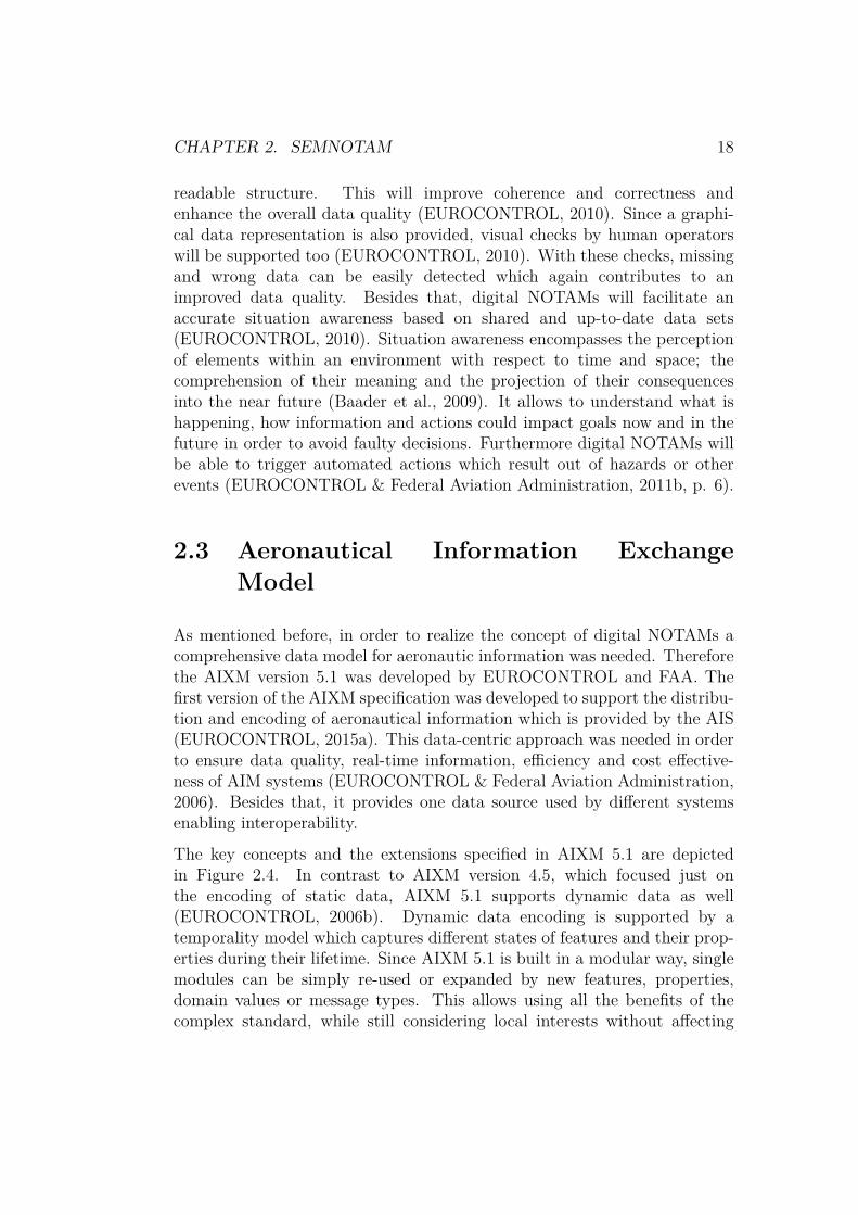
As mentioned before, in order to realize the concept of digital NOTAMs acomprehensive data model for aeronautic information was needed. Thereforethe AIXM version 5.1 was developed by EUROCONTROL and FAA. Thefirst version of the AIXM specification was developed to support the distribu-tion and encoding of aeronautical information which is provided by the AIS(EUROCONTROL, 2015a). This data-centric approach was needed in orderto ensure data quality, real-time information, efficiency and cost effective-ness of AIM systems (EUROCONTROL & Federal Aviation Administration,2006). Besides that, it provides one data source used by different systemsenabling interoperability.
The key concepts and the extensions specified in AIXM 5.1 are depictedin Figure 2.4. In contrast to AIXM version 4.5, which focused just onthe encoding of static data, AIXM 5.1 supports dynamic data as well(EUROCONTROL, 2006b). Dynamic data encoding is supported by atemporality model which captures different states of features and their prop-erties during their lifetime. Since AIXM 5.1 is built in a modular way, singlemodules can be simply re-used or expanded by new features, properties,domain values or message types. This allows using all the benefits of thecomplex standard, while still considering local interests without affecting

CHAPTER 2. SEMNOTAM 19
Figure 2.4: Key concepts and extensions of AIXM version 5.1 (EUROCON-TROL & Federal Aviation Administration, 2006).
the global interoperability (EUROCONTROL, 2006a). Furthermore, AIXM5.1 includes International Organization for Standardization (ISO) standardsfor geospatial information such as ISO19100 providing a framework fordeveloping geography-based domain specific standards and providing meta-data about geographic information. Moreover it includes and extends theGeography Markup Language (GML) XML Schema version 3.2 which is aninternational standard for exchanging geographical features.
AIXM is compliant with the ATM Information Reference Model (AIRM).Besides AIXM, the ATM provides additional data exchange models suchas the Flight Information Exchange Model (FIXM)2 used for sharinginformation about flights throughout their life-cycle and the WeatherInformation Exchange Models and Schema (WXXM)3 for meteorologicalinformation (Burgstaller et al., 2015). AIRM satisfies the need of ensuringsemantic interoperability within ATM by providing understandable, clearly,structured, harmonized, and uniquely defined ATM business term defini-tions (EUROCONTROL, 2012, p. 1). It contributes to the System WideInformation Management (SWIM) ensuring that information is not alteredor lost while it is used (EUROCONTROL, 2012, p. 1)(Burgstaller et al.,2015).
2http://www.fixm.aero/3http://www.wxxm.aero/

CHAPTER 2. SEMNOTAM 20
2.3.1 eXtensible Markup Language
The data structure behind AIXM is XML which is ideal for data sharingbetween different systems. XML is used for representing semi-structuredinformation such as documents, configurations or data. It is a simple text-based format used for sharing structured information (W3C, 2015). The mainadvantages of XML is that it is self-describing, independent of programminglanguages, data base structure and hardware and it can be easily extended(EUROCONTROL, 2006c, p. 2). XML represents a hierarchical structureincluding elements with attributes. These XML elements can contain text orother XML elements. Every XML element must be closed by an appropriateXML end element in order to be considered as well-formed. Well-formedXML documents assure that the document is syntactically correct. However,it is also possible to validate an XML document against a given XML Schema.As stated by (W3C, 2015), na XML Schema represents a description of a typeof XML document. There are various different languages such as Schematron,Relax-NG, Document Types Definitions, and, the most used, XML SchemaDefinition (XSD). XML Schemas are used to associate types with valuesfound in the XML documents; furthermore it is possible to define a list ofallowed elements and their attributes. Besides that it is possible to constrainwhere elements and attributes can be used and what content is allowed withinthose elements. However the most important property is to use the XMLSchema as a human-readable as well a machine-processable documentationincluding formal descriptions of the document.
2.3.2 AIXM Conceptual Model and XML Schema
The AIXM specification is large and complex, covering various aeronauticaldata of ATM elements, their attributes and their relations. It provides overone hundred different features and data types. However, two main parts canbe identified. The logical information model and a data exchange format(EUROCONTROL, 2015a). Both parts can be and are still extended andprovide extensive capabilities supporting temporal models and geographicaldata.
AIXM Conceptual Model: the conceptual model of the aeronauticaldata was specified using the visual Unified Modelling Language (UML)which allows to describe behaviour, relationships and abstract con-cepts (EUROCONTROL, 2006a). It is widely used and a de factomodelling standard with an extensive tool support allowing to con-

CHAPTER 2. SEMNOTAM 21
vert UML diagrams to programming languages, database structuresor XML schemas. UML is therefore used to model concepts definedin the Aeronautical Information Conceptual Model (AICM) (EURO-CONTROL, 2006c). The AICM represents the logical basis for AIMdatabases and provides a common conceptual understanding. Com-prised concepts amongst other are aerodromes, airspaces, NAVAIDsand fixes, routes, procedures and organizations and services:
• The Airspace Concept represents a region of any three dimensionalspace in the air with aeronautical significance such as restrictedareas or air traffic control sectors (EUROCONTROL, 2006c, p.17). An airspace can be defined by a single airspace using poly-gons including the range of the altitude and horizontal borders orcombined by other primitive airspaces.
• The area describing the structure of airport and heliports can bespecified using the Aerodrome Concept. This covers definitions ofrunways, taxiways, limitations, obstacles, aircraft parking placesand airport time tables.
• In order to define significant points in space which are neededfor air traffic control and navigational purposes the NAVAID andDesignated Points Concept is used. NAVAIDs are also used toprovide landing aids (EUROCONTROL & Federal Aviation Ad-ministration, 2006).
• Routes for flights are defined by a series of significant points defin-ing route segments (EUROCONTROL, 2006c, p. 20). Each routesegment contains information of the minimum en-route altitude,traffic flow restrictions and operating hours which is all comprisedin the Routes Concept.
• Standard arrival routes, departure procedure and instrument ap-proach procedures are defined within the Procedure Concept con-sidering operating hours of the aerodrome and obstacles (EURO-CONTROL, 2006c, p. 21). Again significant points are used todefine procedure segments.
• Information about aerodromes, procedures, NAVAIDs andairspaces are provided by various services (EUROCONTROL,2006c, p. 22). In order to describe divisions, units, organiza-tions and their provided services, the Service Concept is used.Furthermore this concept allows to model connections betweenaeronautical elements which are provided by the services.

CHAPTER 2. SEMNOTAM 22
Figure 2.5 depicts how these conceptual areas are modelled within UMLusing features, attributes and associations. They represent important
Figure 2.5: UML example of an conceptual area (EUROCONTROL & Fed-eral Aviation Administration, 2006).
aeronautical entities such as runway, aerodromes or routes. Since theyare central entities they are modelled as UML classes (EUROCON-TROL & Federal Aviation Administration, 2006). Each of them ischaracterized by various elements such as the boundaries of runways.Multiple features can be associated to each other using relationshipsindicating for example that a specific runway is situated at an aero-drome (EUROCONTROL & Federal Aviation Administration, 2006).Moreover, AIXM allows to define plausibility checks on the data andbusiness rules.
XML Schema: after defining the concepts within UML, an exchangemodel to transfer them is needed. Such an exchange model for aero-nautical data is provided by the AIXM XML Schema which is definedusing XSDs. It is derived from the AIXM Conceptual Model and al-lows system-to-system exchange of aeronautical information. Due toits size and complexity it is not addressing flight personnel, instead itensures that automated systems can communicate correctly with eachother. As mentioned before, XSDs are used to define attributes, asso-ciate them with types and model simple or nested elements. Basically,the AIXM exchange format consists of three main UML files. The

CHAPTER 2. SEMNOTAM 23
first one4 defining AIXM base feature and object constructs such asabstract features, time slices, objects and property types. The secondone5 defining data types used within the UML model and the thirdone6 representing all other features and their properties.
2.3.3 Temporality Model
Since each aeronautical feature instance is affected by time, the AIXMprovides a model to consider temporality. Every feature has a lifetime whichis determined by its start and end of life (EUROCONTROL & Federal Avi-ation Administration, 2010, p. 5). Moreover, the features properties and therelationships to other features can change during the lifetime. This can resultin properties which are not defined over a time period. A key assumptionof the temporality model is that each property and relationship can changepermanently or temporally, except the global unique feature identifier. Itconsists of two main components. Events which represent changes of one ormore feature properties and states which represent valid feature propertiesover a time period (EUROCONTROL & Federal Aviation Administration,2010, p. 6). Events occur during transitions between states. So called"Time Slices" are used to describe feature properties during states and events.
As depicted in Figure 2.6, a time slice is a container including alltime varying properties of the features. Moreover, it defines how long avalue is set for which property. Since each feature can contain multipleTime Slices, the sequence number is used as an identifier for them withina feature (EUROCONTROL & Federal Aviation Administration, 2010,p. 11). This sequence number also allows to update or replace alreadycommunicated Time Slices. As changes can be conducted temporally orpermanently, different types of Time slices are provided. A BASELINETime Slice describes the state of a feature which results of a permanentchange (EUROCONTROL & Federal Aviation Administration, 2010, p.12). In contrast to that, a TEMPDELTA Time Slice is used to define atemporal feature state. In order to describe the differences of a featurestate which results of a permanent change, PERMDELTA Time Slices are
4http://www.aixm.aero/gallery/content/public/schema/5.1/AIXMAbstractGMLObjectTypes.xsd
5http://www.aixm.aero/gallery/content/public/schema/5.1/AIXMDataTypes.xsd
6http://www.aixm.aero/gallery/content/public/schema/5.1/AIXMFeatures.xsd

CHAPTER 2. SEMNOTAM 24
used. To communicate the current status of a feature, the baseline dataand any active temporal data needs to be merged; this is provided by theSNAPSHOT Time Slices.
Figure 2.6: UML concept of a time slice (EUROCONTROL & Federal Avi-ation Administration, 2006).
Time Slices describe the features and their properties for a given time period.However there are properties which do not contain constant values duringtheir validity of time (EUROCONTROL & Federal Aviation Administration,2010, p. 13). Properties can have cyclic varying values with an associatedtimetable. This timetable describes the times when a given value is used forthese properties. To incorporate these timetables, the temporality modelprovides the concept of schedules. These schedules avoid the generationof a BASELINE or/and TEMPDELTA time slices every time the featureproperty state is changed.
The dynamic content of NOTAMs can be represented by this tempo-rality concept. Time Slices and schedules consider the fact that the contentof NOTAMs can change during their life-time. Based on this, dynamicinformation can be encoded in a structured and machine readable way whichis needed for the SemNOTAM system (Section 2.1).
2.3.4 Geographic Model
The geographical model of AIXM is based on the GML Encoding Standardin order to express geographical features. GML can be used as a modelling

CHAPTER 2. SEMNOTAM 25
language, as well as an interchange format for geographic data (EUROCON-TROL, 2006a). Using the GML Schema, it is possible to express geometriessuch as lines, curves, points, polygons or surfaces.
It is important to notice that the AIXM exchange model is based ona subset of the GML, so called profiles. This leads to AIXM featureswhich are basically GML features and AIXM objects which are GMLobjects (EUROCONTROL, 2008, p. 12). Furthermore, AIXM follows theGML object-property concept which prohibits that a GML object has animmediate child representing another GML object (EUROCONTROL, 2008,p. 12). Applied to AIXM, this means that an association between twofeatures respectively between a feature and an object must be establishedover a property of the feature (EUROCONTROL, 2008, p. 12). Theimplementation of the object-property concept is realized by declaring atype and assigning properties to it. These properties include attributes aswell as relationships. The declared type will be then assigned to features(EUROCONTROL, 2008, p. 12).
Figure 2.7: AIXM extensions of the GML (EUROCONTROL & FederalAviation Administration, 2007).
As depicted on figure 2.7, AIXM uses a 2.5 Dimension (2.5D) representationof the GML geometry model (EUROCONTROL & Federal Aviation Admin-istration, 2007). A 2.5D representation is used in order to encode geometricelements above the earth’s surface. Therefore the vertical distance from theMean Sea Level to the to the highest point on the geometry is added as the

CHAPTER 2. SEMNOTAM 26
elevated property "elevation". Furthermore the height of the geometry isencoded within the vertical extent. All the properties are defined regardinga vertical accuracy. The definition of 2.5D geometries is used in AIXM forATM elements such as airspaces or routes.
As mentioned in Section 2.1.3, the query interfaces allows to considercriteria such as the location in space. Therefore a geometry is specifiedas input. The geometry is analysed in order to detect an overlappingwith geometries of NOTAMs. When the geometry of a NOTAM intersectsthe specified geometry, then the NOTAM is relevant. The detection ofgeographic intersection is done by checking whether the specified geometryis intersected horizontally or vertically by any other NOTAMs geometry.Since geometries can encode polygons, curves or complex surfaces, this isnot a trivial task. To ease the computational effort GML allows to modelenvelopes. These envelopes define the bounding box of a geometry. Abounding box is the smallest horizontal rectangle comprising all the pointsof a geometry.
Using the capabilities of GML, AIXM is able to cover all relevant ge-ographical elements needed within the ATM. Furthermore it provides moredetailed geometries definitions than used in prior versions of AIXM. Thisimproves the filtering capabilities since the intersection works with moreaccurate data than using only the radius of influence. Thus intersections ofirrelevant NOTAMs are avoided.
2.3.5 Feature Identification and Reference
As mentioned in Section 2.3.3, each AIXM feature is identified throughthe use of the identifier property. This property is the only time-invariantone and therefore it is situated outside the TimeSlice complex object(EUROCONTROL & Federal Aviation Administration, 2011a, p. 5).In order to provide feature identification, the AIXM 5.1 schema relieson Universal Unique Identifiers (UUIDs) as feature identifiers. Theseidentifiers fulfill two essential requirements; they are unique and universal,which means that the same identifier will never be used unintentionallyby anyone else and that the same identifier can be used in all systemsto identify a given AIXM feature. It is important to notice that anidentifier does not identify a feature itself, it identifies the data thatsomeone has about a feature. When two systems use the same identifierfor a feature, it indicates that the data is retrieved from one source or that

CHAPTER 2. SEMNOTAM 27
there are processes ensuring consistency between the data of the two systems.
Since AIXM is used to distribute information to various consumers,the possibility to manage linkages between aeronautical features is sup-ported. Therefore the AIXM schema utilizes the XML Linking Language(XLink) schema which is bundled within GML (EUROCONTROL & FederalAviation Administration, 2011a, p. 10). XLink is a standard for representinga reference between two XML elements, which represent AIXM features. Itallows to address individual XML elements which are located within thedocument or available over external sources.
The capability to uniquely identify an AIXM feature allows referenc-ing it. Supporting references avoids redundancy and improves consistencysince data can be maintained at one place and referenced from anywhere.
2.4 ObjectLogic
Besides the AIXM representation for structured data, the SemNOTAMsystem requires a knowledge-based representation. Therefore the deductiveand object oriented database language OL is used. OL combines theexpressiveness and declarative semantics of deductive data base languageswith the modelling capabilities supported by object orientation. It is asuccessor of F-Logic which was developed by (Kifer, Lausen, & Wu, 1995) in1995. F-Logic is an ontology and knowledge representation language used forontology management, semantic web services, information integration andintelligent agents. Since F-Logic was developed to overcome the relationalapproach of predicate logic, it already comprises the object-orientatedconcepts which are used in OL. Since OL is also used to represent knowledgeit provides rules in order to derive new knowledge. Furthermore queries forfiltering that knowledge base are supported.
OL is based on the Closed World Assumption (CWA). This assump-tion is crucial for the reasoning task, since a CWA implies that all availableknowledge is complete. Everything which is not known is assumed to befalse e.g. an aircraft has a pilot named Bob, the reasoner would determinethat there is only one pilot for that aircraft. In contrast to that the OpenWorld Assumption (OWA) implies that all available knowledge is true butnot complete. This means for the given example that the aircraft has apilot named Bob but it can have other pilots too, it is just not known. This

CHAPTER 2. SEMNOTAM 28
difference seems slight, but when a query is conducted to filter aircraft withonly one pilot, then only the CWA based reasoner will return the aircraft.
The tool support for OL is restricted to OntoStudio and OntoBrokersince OL exclusively provided by semafora systems GmbH. The OntoBrokeris the reasoner for OLOL and includes the knowledge base and an API(OntoAPI) in order to access it. The OntoStudio provides a graphicalinterface for the supported operations of the OntoAPI.
The following description provides an insight of the OL concepts andexamples explaining them. Since semafora systems GmbH are exclusivelydeveloping OL, they are the only source of documentation for it. Thereforethe following explanations refer to the OL Tutorial (semafora systemsGmbH, 2012) and the OL Reference (semafora systems GmbH, 2013).
Basic Syntax: Factual knowledge is defined in OL by objects, theirrelationships, and classification. This kind of knowledge is also knownas the explicit knowledge. In contrast to that the intensional knowledgerepresents the implicit knowledge derived by applying rules. Both theintensional and the factual knowledge can be queried. All these entitiesof an OL program which can be queried must be named.
1 Jet. // term as class name2 Jet[ maxSpeed -> 800] // term as method name3 jet123_3 :Jet. // term as object name4
5 ?- eurofighterX [ crewMember -> ?Y]. // term as queryvariable ?Y
Listing 2.1: Example of terms.
As shown in Listing 2.1, OL provides terms for naming entities. Termscan be used as constants or to name classes, object or methods. Termsused to name classes, objects or methods are called id-terms and startwith a letter followed by letters, digits or underscores. Terms are alsoused for variables, which are only used within rules and queries. Theyfollow the same grammar as id-terms except that they start with aquestion mark. Moreover terms can represent methods including thename and a list of one or more terms within braces.
Schema Level Statements: OL supports the object-oriented concepts ofclasses and attributes. Therefore the schema provides a vocabulary al-lowing to define classes, attributes and applicable methods. Using this

CHAPTER 2. SEMNOTAM 29
vocabulary, OL allows to define complex class hierarchies. Furthermorevarious methods and class attributes can be defined this way, providingthereby type-safety and constraints regarding the cardinalities.
Subclass-F-atoms allow to define subclass relationships betweentwo classes. The classes are denoted by id-terms. Multiple inheritancesof several classes are permitted in OL.
1 Jet.2 Jet :: Aircraft .
Listing 2.2: Example of a subclass-F-atom.
As shown in Listing 2.2, a class "Jet" is defined. The subclass-F-atom isused to define hierarchical structure declaring that a "Jet" is a subclassof an "Aircraft". Subclass relationships are denoted by "::".
Signature-F-atoms are used to define methods of a class and typerestrictions for parameters and results. Moreover, each method canbe restricted by a given cardinality, which determines how many en-tries may be provided at least respectively at most. It is important tonote that attributes of a class are modelled as methods without anyparameter. Therefore methods without any parameter will be namedattributes in the following sections.
1 Pilot :: Person .2 Jet[type {1:1} *=> xsd# string ].3 Jet[pilot(xsd#date) {1:*} *=> Person ].4 Jet[pilot(xsd#date) {1:*} *=> Pilot ].
Listing 2.3: Example of several signature-F-atom.
The Listing 2.3 starts with defining a class "Pilot" which extends "Per-son" using a subclass-F-atom. The first signature-F-atoms defines forthe domain "Jet" an attribute named "type" with an range "xsd#string".Moreover, the cardinalities indicate that there must be exactly one"type" provided. The domain defines which class is affected and therange determines which types respectively classes can be used as val-ues. The following two signature-F-atoms define the method "pilot"which can be used to determine the pilot(s) of a jet. As shown, the

CHAPTER 2. SEMNOTAM 30
method "pilot" accepts a parameter of the type "xsd#date" indicatingsince when a given pilot is the pilot of the jet. Furthermore, thesetwo signature-f-atoms show also that the concept of method overload-ing is provided since both share the same method signature. The onlydifference is determined by the specified range.
Instance Level Statements: Based on a defined schema, instance levelstatements can be used to create objects. These objects represent in-stances of the predefined classes. However a valid OL program does notneed to have existing schema level statements. It is also valid withoutthem, when the basic syntax is not violated.
F-atoms are also know as isa-F-atoms which are used to instantiateclasses. With isa-F-atoms the class membership is denoted by a singlecolon separating two id-terms, representing the instance (object) andthe class. OL allows the multiple instantiation of several classes.
1 eurofighterX :Jet.2 eurofighterY :Jet.
Listing 2.4: Example of a isa-F-atom.
A simple instantiation of one class "Jet" is depicted in Listing 2.4.
Data-F-atoms are used to apply methods on objects which wereinstantiated using f-atoms. Data-F-atoms represent the instance ofsignature-F-atoms and therefore they consist of a host object (domain),a method and a value which denoted by id-terms. The value can beeither an object or a literal.
1 eurofigtherX [type -> " Eurofigther Typhoon "].2 mary: Person .3 bob:Pilot.4 eurofigtherX [pilot (2012) -> mary ].5 eurofigtherX [pilot (2011) -> bob ].
Listing 2.5: Example including several data-F-atoms.
Listing 2.5 shows how the methods of the previously instantiated object"eurofigtherX" are used. The attribute "type" is set to "Eurofigther Ty-phoon"; moreover, a person "mary" and a pilot "bob" are instantiated.

CHAPTER 2. SEMNOTAM 31
It would also be possible to multiple instantiate "bob" using other OLclasses. These two individuals are used for the usage of the objects’"pilot" methods. Both methods receive a year as input parameters.
F-molecules allow to collect information about an object, by com-bining multiple f-atoms statements. Furthermore f-molecules can alsobe used to combine subclass-F-atoms and signature-F-atoms. The pre-vious OL examples can be rewritten to the following OL program 2.6based on f-molecules.
1 // Schema Level statements2 Pilot :: Person .3 Jet[type {1:1} *=> xsd#string , pilot(xsd#date) {1:*}
*=> {Person , Pilot }].4
5 // Instance Level statements6 mary: Person .7 bob:Pilot.8 peter: Person .9 anna: Person .
10
11 eurofighterX :Jet.12 eurofighterY :Jet[type -> " Eurofigther Typhoon ",
pilot (2012) -> mary , pilot (2011) -> bob ,controller -> {peter , anna }].
Listing 2.6: Example of a F-molecule.
F-molecules allow to combine the data-F-atoms and isa-F-atoms whichresults in a more readable OL program. An object and its correspond-ing methods and attributes can be defined within only one statement.The Listing 2.6, is enriched by the attribute "controller" which indicateswho is the responsible air traffic controller. As stated before, even ifthat attribute is not defined in the schema, it is still valid. Furthermoreit can be seen that multiple values can be assigned to one attribute atonce. When more than one values is set for an attribute at once, thevalues must be enclosed within braces. The usage of the method "pilot"of the "eurofighterY" object cannot be grouped to one statement sinceeach of them have a different parameter. If both methods would receivethe same parameter "2012" then a grouping to "pilot(2012) -> {mary,bob}" would be possible.

CHAPTER 2. SEMNOTAM 32
Namespaces: a term can be used multiple times representing different se-mantics. Besides using a term multiple times, a term can have differentmeanings (synonyms). Furthermore, the same id-term can be used inmultiple knowledge bases which can lead to problems when they getmerged. To overcome these issues, OL provides namespaces. Names-paces are used in the context of the Semantic Web to uniquely identifyobjects and instances. Therefore they can also be used to handle multi-ple definitions of concepts (classes) in different knowledge bases. Eachnamespace must represent a valid identifier according to RFC 2396 andmust end with either "#", "/", or ":". These last characters mark theseparator between the namespace and the local part of an identifier.
1 :- prefix aero = "httm :// www.aixm.aero/ schema /5.1#".2 airlinerX :aero# Aircraft [aero#id -> "Boeing747 -123"].
Listing 2.7: Example of using a namespace.
As shown in Listing 2.7, it is possible to define prefixes for names-paces. These prefixes act as a place holder for the namespace, avoidingto rewrite the whole namespace identifier before each term. When anamespace respectively a prefix is used to identify a term, then theseparator symbol "#" must be placed between the prefix and the term(local name).
Rules: OL rules are used to extend the knowledge base by deriving newinformation. Whenever a precondition of a rule is satisfied, the conclu-sion is true. The preconditions represents the rule body and is formedby combining F-molecule by logical conjunction such as OR, NOT andAND. The rule head is also represented by a conjunction of F-moleculesand is separated from the rule body by the symbol ":-". Variables areused within rules as place holders. However, variables used in the rulehead must also be used in the rule body.
1 ?X[ coPilot -> ?Y] :- ?X: Aircraft [ flightCrew -> ?Y]AND ?Y:Pilot AND NOT ?X[ captain -> ?Y].
Listing 2.8: Simple rule defining the aircrafts’ co-pilot.
Listing 2.8 depicts a simple rule. The rule head defines that a object"?X" has the attribute "coPilot" with the value "?Y" when the rule bodyis satisfied. The rule body comprises the conditions which need to befulfilled; in this case the variable "?X" must be an aircraft and "?Y"

CHAPTER 2. SEMNOTAM 33
must be a member of the flight crew. Furthermore, "?Y" must be apilot who is not the captain of the aircraft "?X". Using this rule theimplicit knowledge that "a flight crew member who is a pilot but notthe captain of the aircraft is assigned as a co-pilot" can be derived.
Queries: To access the explicit and derived knowledge, OL providesqueries. Syntactically a query can be considered as a special kind of arule with an empty head. Queries start with the symbol "?-" followedby conditions which need to be satisfied. These conditions are denotedby f-molecules including unbound variables. The unbound variables areused to determine which objects are queried respectively which objectwill be in the result set. Queries retrieve results based on derived andexplicit available facts.
1 ?- eurofighterX [ crewMember -> ?Y].
Listing 2.9: Example a simple query.
The query depicted in the example 2, retrieves all crew members of thejet "eurofighterX".
Chapter 3
Requirements Analysis
Contents3.1 Task Description . . . . . . . . . . . . . . . . . . . 34
3.1.1 NOTAM Data . . . . . . . . . . . . . . . . . . . . 363.1.2 Configuration Data . . . . . . . . . . . . . . . . . . 383.1.3 Query Data . . . . . . . . . . . . . . . . . . . . . . 39
3.2 Requirements . . . . . . . . . . . . . . . . . . . . . 423.3 Challenges and Problems . . . . . . . . . . . . . . 44
This section specifies the requirements of the mapping task. Therefore thetask description will be detailed and examined. Based on this the require-ments will be determined and analysed. Moreover, it provides an insight ofpossible problems which can occur. The identified requirements will be thenused in Section 5 to design an appropriate architecture and to select suitabletechnologies.
3.1 Task Description
A coarse description of the mapping task is given in Section 1.1 andSection 2.1. It is stated there that the mapping will transform a givenstructured data set into a knowledge representation. In the subsequentsections this task is substantiated to a mapper between an XML-based
34

CHAPTER 3. REQUIREMENTS ANALYSIS 35
and an OL representation. This section will specify this task by providingdetailed description of the data sources, their usage and their structure.
The main task of the mapping is the transformation of several struc-tured input sources to an OL representation. These input sources aredepicted in figure 3.1 and represent the data structures introduced in theSemNOTAM system (Section 2.1). Each of the depicted data sources willbe processed sequentially.
Figure 3.1: Mapping tasks of the AIXM to ObjectLogic Mapper.
Since the XML schemas are still being developed, the available data sourcesare restricted to NOTAMs, segments and queries. However, other sourcessuch as aircraft data will be supported in the future which can lead to newdata sources. Each data source is described through XSD document(s).
The three sources depicted in Figure 3.1 must be handled by the mapper.The AIXM to OL Mapper must accept these three XML documents whichwill be parsed to corresponding OL files. The resulting segment, queryand NOTAM OL files will then be inserted into the knowledge base. Thisknowledge base is accessible over the OntoAPI of the OntoBroker. Thequery OL files will be saved and processed by another component. Duringthe mapping process not information must be lost since the data sources,especially NOTAMs, can contain safety critical information. However,information which does not add any knowledge need to be omitted to avoidclutter. That are XML attribute elements which are empty, contain noXML attributes and do not represent an association.

CHAPTER 3. REQUIREMENTS ANALYSIS 36
Furthermore, it must possible to configure the mapper. Examples forconfiguration parameters are the source XML file name, the output OLfile name, credentials for accessing the OntoAPI and whether a newontology will be created or an existing extended. The mapper has toperform preprocessing tasks, such as the calculation of the bounding box ofAIXMBasicMessages and their features. This will ease later computationalsteps on OL. Besides these functions, the time at which the NOTAMs havebeen processed will be stored within a detection time stamp. This timestamp is needed for so called delta queries which should determine changesin the knowledge base. These changes are relevant because they indicateupdates of already mapped data sources.
Since not all sources and therefore possible preprocessing steps are known,the parser must be extensible without changing the existing implementation.Possible preprocessing steps in the future could be the classification ofNOTAMs according to their corresponding flight information region, airtraffic service (ATS) segments, or airport. Other classifications could includea specific standard instrument departure (SID) or/and standard terminalarrival route (STAR).
The following subsections details the three data sources depicted inFigure 3.1. For each data source the structural representation encoded inXML will be analysed. Therefore it will be examined which informationis stored in which XML elements. Moreover, possible content of the XMLelements and their corresponding OL representation will be introduced.
3.1.1 NOTAM Data
NOTAMs in AIXM are represented by AIXMBasicMessages. TheAIXMBasicMessage is available as XML data and will be transformedinto OL. An AIXMBasicMessage contains multiple AIXM features which areincluded within the hasMember association.
1 <ns13:AIXMBasicMessage ns5:id="FNS_ID_34828025">2 <ns5:boundedBy xsi:nil="true"3 xmlns:xsi="http://www.w3.org/2001/XMLSchema-instance" />4 <ns13:hasMember>5 <ns10:Event ns5:id="Event_1_34828025">6 <ns5:boundedBy xsi:nil="true"

CHAPTER 3. REQUIREMENTS ANALYSIS 37
7 xmlns:xsi="http://www.w3.org/2001/XMLSchema-instance" />8 <ns10:timeSlice>9 <ns10:EventTimeSlice ns5:id="Event_TS_1_34828025">
10 <ns5:validTime>11 <ns5:TimePeriod ns5:id="Event_TS_TP_1_34828025">12 <ns5:beginPosition>2013-02-12T21:51:00.000Z</ns5:
beginPosition>13 <ns5:endPosition indeterminatePosition="unknown" />14 </ns5:TimePeriod>15 </ns5:validTime>16 <ns6:interpretation>BASELINE</ns6:interpretation>17 <ns10:scenario>6000</ns10:scenario>18 <ns10:extension>19 <ns11:EventExtension ns5:id="ext_01_34828025">20 <ns11:classification>INTL</ns11:classification>21 <ns11:accountId>KIAD</ns11:accountId>22 <ns11:xoveraccountID>FDC</ns11:xoveraccountID>23 <ns11:xovernotamID>3/8008</ns11:xovernotamID>24 <ns11:airportname>WASHINGTON DULLES INTL</ns11:
airportname>25 <ns11:originID>KIAD</ns11:originID>26 <ns11:lastUpdated>2013-09-30T10:50:00.000Z</ns11:
lastUpdated>27 <ns11:icaoLocation>KIAD</ns11:icaoLocation>28 </ns11:EventExtension>29 </ns10:extension>30 </ns10:EventTimeSlice>31 </ns10:timeSlice>32 </ns10:Event>33 </ns13:hasMember>34 </ns13:AIXMBasicMessage>
Listing 3.1: Example of a NOTAMs encoded as an AIXMBasicMessage.
AIXM features can be used to represent events introduced in Section 2.2.1and Section 2.3.3. As depicted in Listing 3.1, the AIXMBasicMessage con-tains an Event as a member. Since the values within a NOTAM can vary,a time slice feature for the event is provided (Section 2.3.3). Furthermore,it is shown that identifiers for the feature elements are provided, whereasthe associations are not identified explicitly. The boundedBy element isempty since no GML information is provided in Listing 3.1. However,GML information can be encoded within NOTAMs. Moreover, it is shownthat the AIXMBasicMessage which is used for encoding the NOTAMs,follows the object-property concept of GML (2.3.4). Besides XML ele-ments and their attributes a NOTAM can contain text as content. AIXMallows to formate this text using HyperText Markup Language (HTML) tags.

CHAPTER 3. REQUIREMENTS ANALYSIS 38
Using the NOTAM in Listing 3.1 as an input, the AIXM to OL Map-per has to produce the corresponding OL output as depicted in Listing 3.2.
1 FNS_ID_34828025:ns13AIXMBasicMessage[ns5id->"FNS_ID_34828025",ns13hasMember->Event_1_34828025].
2
3 Event_1_34828025:ns10Event[ns5id->"Event_1_34828025", ns10timeSlice->Event_TS_1_34828025, ns5boundedBy -> "xsi:nil"].
4
5 Event_TS_1_34828025:ns10EventTimeSlice[ns5#d->"Event_TS_1_34828025",ns5validTime->Event_TS_TP_1_34828025, ns6interpretation->"BASELINE", ns10scenario->"6000", ns10extension->ext_01_34828025].
6
7 ext_01_34828025:ns11EventExtension[ns5#id->"ext_01_34828025",ns11originID->"KIAD", ns11xoveraccountID->"FDC", ns11classification->"INTL", ns11airportname->"WASHINGTON DULLES INTL",ns11lastUpdated->"2013-09-30T10:50:00.000Z", ns11icaoLocation->"KIAD", ns11xovernotamID->"3/8008", ns11accountId->"KIAD"].
8
9 Event_TS_TP_1_34828025:ns5TimePeriod[ns5id->"Event_TS_TP_1_34828025",ns5endPosition("indeterminatePosition")->"unknown",ns5beginPosition->"2013-02-12T21:51:00.000Z"].
Listing 3.2: Example of an AIXMBasicMessage represented in an OLrepresentation.
As shown the AIXMBasicMessage and its features are represented by f-molecules. Each of these f-molecules is defined using the given identifier,such as "FNS_ID_34828025", as the id-term. The XML attributes of theAIXMBasicMessage are mapped to OL attributes. These OL attributes areadded to the f-molecule using data-F-atoms. Moreover, the associations tothe direct AIXM child features are mapped to OL. These associations are setby adding OL methods which receive the id-term of the AIXM child featuresas a value.
3.1.2 Configuration Data
As stated in Section 2.1.3, configuration data is used to define route segmentsand aircraft characteristics. Since currently the segments are used as inputsources, the aircraft characteristic will be left aside. However, it must beconsidered that they will be available in the near future. A route consists ofseveral segments (Section 2.3.2). Each segment is defined by a start and anendpoint (Cordell, 2006). Beside these two points, segments are composed

CHAPTER 3. REQUIREMENTS ANALYSIS 39
of consecutive connected significant points. These significant points can beused by multiple routes. Therefore it is possible to reference them.
1 <Collection xmlns="http://semnotam.frequentis.com/SegmentSchema"2 xmlns:xsi="http://www.w3.org/2001/XMLSchema-instance"3 xsi:schemaLocation="http://semnotam.frequentis.com/SegmentSchema ./
SegmentSchema.xsd"4 xmlns:gml="http://www.opengis.net/gml">5 <hasMembers>6 <Segment>7 <id>1212</id>8 <shape>9 <gml:PolygonPatch>
10 <gml:exterior>11 <gml:LinearRing>12 <gml:posList>38.9353015690001 -77.45848128913 38.93530156900009 -77.45848128899996
38.935869824000114 -77.458208563 38.9359786850001
-77.4581544315 </gml:posList>16 </gml:LinearRing>17 </gml:exterior>18 </gml:PolygonPatch>19 </shape>20 </Segment>21 ...22 </hasMembers>23 </Collection>
Listing 3.3: Example of segments encoded in XML.
As shown in Listing 3.3, segments can be encapsulated in a collection ofsegments. Each segment is identified by an identifier and contains a GMLshape. This GML shape consists of several coordinates representing a geom-etry. Segments follow object-property concept of GML since they are basedon GML shapes. In Listing 3.3, the represented geometry is a linear ring.
3.1.3 Query Data
The parsing of the query will neither lead to a resolution of the query norto the correct interpretation of it. It will transform the XML documentcontaining the query to its corresponding OL representation. The resolutionof the query and the interpretation of it will be done in a separate module.

CHAPTER 3. REQUIREMENTS ANALYSIS 40
As stated in Section 2.1 the query will support the combination of variousinterests. As depicted in Figure 3.2 these interests are used to specify queriesregarding aircraft, attributes, periods or areas. It is important to note thatthe area of interests can use the information provided by segments. Like inthe other data source, the object-property model is followed since the querycan be used to query GML information.
Figure 3.2: Query object structure (Steiner et al., 2014, p. 15).
Due to the high modularity of this structure, each queried aspect is rep-resented by a SimpleInterest subclass. These SimpleInterests can becombined to ComplexInterests using logical connectors such as NOT, ORand AND. AND is used for the intersection of two operands, such as theintersection of two relevant sets. OR is used for the union of two sets andNOT is used as the negation of a referenced set. Each query object containsan identifier which needs to be set by the context.In the following the different interests and their attributes will be investi-gated:
• AircraftOfInterest: specifies the attributes of the aircraft which canbe used to filter NOTAMs which are relevant to the described aircraft.
• AttributeOfInterest: refers to AIM elements which are specified inthe SemNOTAM system as concepts. Furthermore they can be used torestrict the values of the result. Combinations of concepts and valuerestrictions are possible.
• PeriodOfInterest: defines the time span which will be consideredduring the filtering. These periods are divided into the two types. Theoccurrence time which describes the valid time of a NOTAM, and thedetection time which describes the time a NOTAM is inserted into the

CHAPTER 3. REQUIREMENTS ANALYSIS 41
SemNOTAM system. Therefore every NOTAM has one valid timespanand a detection time stamp which allows querying from any point ofview in time.
• AreaOfInterest: is used to define restrictions to certain areas, suchas Areas, ScopedAreas, GML Shapes, and segments. Area restrictionsallow to geographically restrict AIM elements such as retrieving the air-port in Linz. ScopeArea restrictions are used to define queries whichretrieve NOTAMs of a specific airport while excluding runways. Foreach exclusion exceptions can be set which allows to exclude all run-ways except a specific one. GML Shapes and segments can be queriedby providing GML data and a buffer. NOTAMs which fit the GMLinformation within the buffer are retrieved.
Besides the querying of current data it is possible to request the changessince the query was last posted to the SemNOTAM system. This is doneby using Delta Queries which are a specialization of normal queries. Due tothe fact that NOTAMs can be corrected, a correction can lead to NOTAMswhich were relevant in the first query but later becoming irrelevant due tothe changes.
1 <Query xmlns="http://semnotam.frequentis.com/QuerySchema"2 xmlns:xsi="http://www.w3.org/2001/XMLSchema-instance" xmlns:rs="http
://semnotam.frequentis.com/ResultSchema"3 xsi:schemaLocation="http://semnotam.frequentis.com/QuerySchema ./
QuerySchema3.xsd"4 xmlns:gml="http://www.opengis.net/gml">5 <id>1</id>6 <interest>7 <ScopedArea>8 <scope>9 <Area>
10 <concept>11 <AreaClass>Airport</AreaClass>12 </concept>13 <restriction>14 <ValueRestriction>15 <attribute>designator</attribute>16 <operator>=</operator>17 <value>MUC</value>18 </ValueRestriction>19 </restriction>20 </Area>21 </scope>

CHAPTER 3. REQUIREMENTS ANALYSIS 42
22 <exclude>23 <Exclusion>24 <exclude>25 <AreaClass>Runway</AreaClass>26 </exclude>27 <except>28 <Area>29 <concept>30 <AreaClass>Runway</AreaClass>31 </concept>32 <restriction>33 <ValueRestriction>34 <attribute>designator</attribute>35 <operator>=</operator>36 <value>MUC_RWY10</value>37 </ValueRestriction>38 </restriction>39 </Area>40 </except>41 </Exclusion>42 </exclude>43 </ScopedArea>44 </interest>45 </query>
Listing 3.4: Example of a simple query encoded in XML.
The query depicted in Listing 3.4, queries all NOTAMs belonging to theairport Munich. The airport includes all existing runways. Therefore allrunways are excluded from the airport except the runway RWY10. It is as-sumed that the designator attribute is specified at NOTAM level. Moreover,it is assumed that the designator for the airport Munich is MUC and that thedesignator for RWY10 is MUC_RWY10.
3.2 Requirements
The task description from Section 3.1 is used in order to determine the re-quirements. The requirements are determined by identifying and extractingthem from the task description. Moreover, they are grouped according theircharacteristics. This results in a listing containing all requirements whichneed to be fulfilled by the design respectively the implementation.
1. Input:
1.1. XML documents have to be processed sequentially.

CHAPTER 3. REQUIREMENTS ANALYSIS 43
1.2. It has to be possible to set the XML-input and OL-output files.
1.3. The mapper has to allow to define mapping parameters, such asthe radius.
1.4. The credentials for accessing the interface must be configurable.
1.5. It has to be possible to define whether a new ontology is createdor an existing one to be extended.
2. Output:
2.1. Query specifications have to be mapped to their equivalent OLrepresentation. They will not be enriched or interpreted.
2.2. Segments have to be mapped to their equivalent OL representa-tion.
2.3. NOTAMs have to be mapped to their equivalent OL representa-tion.
2.4. The OL representation has to be saved to a file.
2.5. An interface for loading OL files into the knowledge base must beprovided.
3. Processing:
3.1. No information must be lost during the mapping task. All fea-tures, their attributes, their relationships and the content of theXML elements have to be included in the OL representation. Es-pecially formatted text must be preserved.
3.2. Local references inside an XML document need to be resolved.This means that instead of the XLink reference statement theidentifier of the referred XML elements has to be used. Externalreferences do not have to be resolved.
3.3. The mapper must provide extension capabilities which allow toadd new mapping and/or preprocessing tasks without modifyingthe existing implementation. An extension example is the calcu-lation of bounding boxes (Requirement 4.1).
3.4. Due to the possibility that the AIXM schema can be extended,the mapper needs consider the different namespaces within theXML documents.

CHAPTER 3. REQUIREMENTS ANALYSIS 44
3.5. A detection time stamp has to be added which represents the timethe data source is mapped.
4. Completing missing information:
4.1. An extension must be provided which completes missing geograph-ical information. If the bounding box of a NOTAM is not avail-able, then it has to be calculated and added to the NOTAM and itsfeatures. Bounding boxes for geographic points will be calculatedwith a given radius.
4.2. Missing identifier attributes of XML elements, which representfeatures, have to be added. These identifier must be unique anduniversal. Unique means that there has to exist a reasonable plau-sibility that the identifier will never be used unintentionally byanyone else. Universal refers to the requirement, that the sameidentifier has to be used in all systems to identify a specific AIXMfeature.
These requirements will be used in further sections, especially the develop-ment of the mapping concept and the selection of the technologies relies onthem.
3.3 Challenges and Problems
The requirements describe the main tasks which must be fulfilled by the map-per. However they are not exhaustive since not all aspects were considered.The resulting ambiguities and their emerging challenges and problems willbe discussed in this section.
Data identification: The mapping task requires a distinction betweenAIXM feature and their relationships. The challenge is to define how featuresrespectively relationships are characterized in order to distinguish them. Therequirements describe only how they have to be mapped to OL but not howto identify them. An approach must be found which generic enough to be ap-plied on all three data sources. This approach must identify characteristics todistinct between AIXM features and their relationships. It must be ensuredthat all features and relationships follow the identified characteristics.

CHAPTER 3. REQUIREMENTS ANALYSIS 45
Exception handling: Moreover, exceptional XML elements must be de-termined such as the HTML tags which are used to format text. It must bepossible to exclude a set of XML elements which will be ignored or treatedas text and therefore not be mapped to an corresponding OL representa-tion. Besides that missing attribute such as the identifier must be handled.It is not exactly specified how the identifier requirements uniqueness anduniversality can be provided.
OL representation: Since no information has to be lost an approach mustbe defined which allows to map all information given in the data sources totheir corresponding OL representation. The mapping described in the re-quirements covers only a basic use case. The handling of the attributes ofXML elements which represent AIXM relationships is not specified. More-over, it is not specified how links have to be added to the OL representation.The OL representation of text is limited to simple text without any format-ting. However, text can be formatted using HTML tags, tabulators, multipleblanks or line breaks. It is not specified how the formatting has to be mappedin order to preserve the formatting in the OL representation.
Namespaces: the requirements state that the mapper has to consider dif-ferent namespaces in the data sources especially in AIXM. The handling ofnamespaces can lead to problems because same prefixes for different names-paces can be used in the data sources. These varying namespace definitionsdoes not conflict within the XML document, but they can lead to conflictswhen they are inserted and merged into the KB of the SemNOTAM system.
Preprocessing: Even the defined preprocessing task is challenging sinceGML elements require a proper handling. The interpretation of coordinatesdepends on the Coordinate Reference System (CRS). CRSs are required dueto the distortions which occur during the plotting of the earths’ surface ontoa map. The CRS is encoded in the attribute "srsName" which needs to beresolved to find the corresponding CRS. Beside that, calculations based onthe geometries must be performed, in order to calculate the bounding box.These calculation again depend on the specified CRS and are not trivialsince the earths surface cannot be interpreted as an flat surface. Insteadit is represented through an ellipsoid which requires complex trigonometricfunctions to determine new spatial points. Moreover, it must be possible totransfer coordinates between different CRSs since not all CRS allow thesekind of calculations.

CHAPTER 3. REQUIREMENTS ANALYSIS 46
Flexibility: Besides the mapping of the data sources to a corresponding OLrepresentation, modification and configuration possibilities must be provided.These modifications are not know currently and therefore the mapper has tobe implemented in a way to support them in the future. Therefore a conceptmust be found to extend the mapper at different points without modifyingexisting implementations.

Chapter 4
Mapping Approach andRealization Options
Contents4.1 Basic Mapping Concept . . . . . . . . . . . . . . 484.2 Mapping Approach . . . . . . . . . . . . . . . . . 52
4.2.1 Namespaces . . . . . . . . . . . . . . . . . . . . . . 524.2.2 Text . . . . . . . . . . . . . . . . . . . . . . . . . . 544.2.3 Attributes of AIXM Attributes . . . . . . . . . . . 554.2.4 Processing Timestamp . . . . . . . . . . . . . . . . 574.2.5 XML Elements with missing Identifiers . . . . . . 584.2.6 Link Resolution . . . . . . . . . . . . . . . . . . . . 634.2.7 Bounding Boxes . . . . . . . . . . . . . . . . . . . 66
4.3 Mapping Technologies . . . . . . . . . . . . . . . . 714.3.1 XSLT . . . . . . . . . . . . . . . . . . . . . . . . . 724.3.2 XML Query Language (XQuery) and BaseX . . . . 754.3.3 SAX and StAX Parser . . . . . . . . . . . . . . . . 784.3.4 DOM Parser . . . . . . . . . . . . . . . . . . . . . 804.3.5 Evaluation and Selection . . . . . . . . . . . . . . . 82
4.4 DOM Extension Capabilities . . . . . . . . . . . 84
47

CHAPTER 4. MAPPING APPROACH 48
In this section the basic mapping concept and the mapping approach areintroduced to fulfill the requirements of Section 3.2. Moreover, the handlingof geographic data is analyzed. Based on the mapping concept a suitabletechnology is chosen. This comprises the analysis and evaluation of thetechnologies which can be used for the mapping task. Furthermore, theextension capabilities of the selected technology are described in Section 4.4.The mapping concept is shown by using AIXM NOTAMs as it can be appliedanalogously to all data input sources since they follow the object-propertymodel. Consequently XML attribute elements and AIXM elements whichrepresent OL attributes are used analogously here. This applies also to XMLobject elements and AIXM features which represent OL objects.
4.1 Basic Mapping Concept
As stated in Section 2.3.2 AIXM follows the object-property model. Thismodel prohibits that an AIXM feature has an immediate child representinganother AIXM feature or object. Therefore every relationship between thesefeatures must be established over a property/attribute of the feature.
1 <ns13:AIXMBasicMessage ns5:id="FNS_ID_34828025">2 <!-- AIXM Feature -->3 <ns5:boundedBy xsi:nil="true" xmlns:xsi="http://www.w3.org/2001/
XMLSchema-instance" />4 <!-- AIXM Attribute -->5 <ns13:hasMember>6 <!-- AIXM Attribute -->7 <ns10:Event ns5:id="Event_1_34828025">8 <!-- AIXM Feature -->9 ...
10 <ns10:timeSlice>11 <!-- AIXM Attribute -->12 ...13 <ns5:beginPosition>2013-02-12T21:51:00.000Z</ns5:
beginPosition>14 <!-- AIXM Attribute -->15 <ns5:endPosition indeterminatePosition="unknown" />16 <!-- AIXM Attribute -->17 ...18 </ns10:timeSlice>
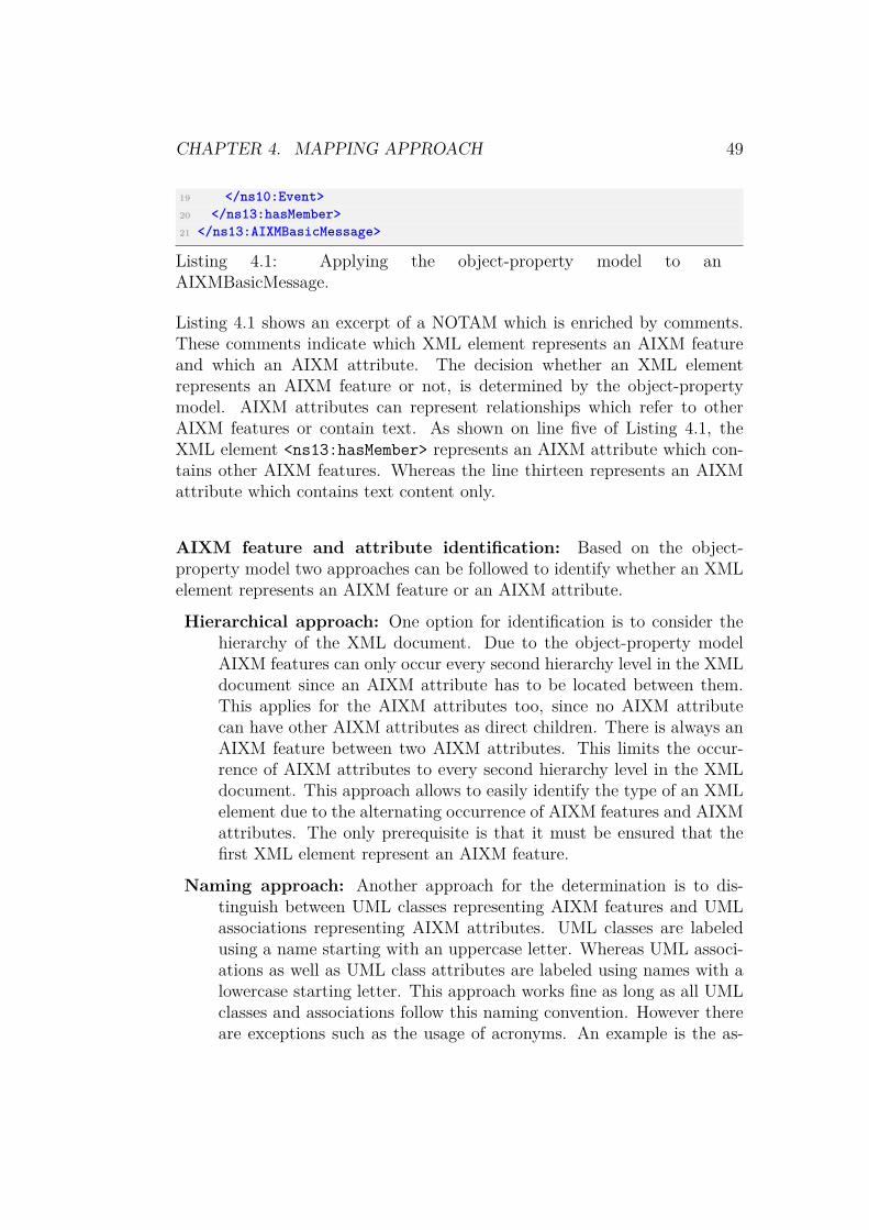
CHAPTER 4. MAPPING APPROACH 49
19 </ns10:Event>20 </ns13:hasMember>21 </ns13:AIXMBasicMessage>
Listing 4.1: Applying the object-property model to anAIXMBasicMessage.
Listing 4.1 shows an excerpt of a NOTAM which is enriched by comments.These comments indicate which XML element represents an AIXM featureand which an AIXM attribute. The decision whether an XML elementrepresents an AIXM feature or not, is determined by the object-propertymodel. AIXM attributes can represent relationships which refer to otherAIXM features or contain text. As shown on line five of Listing 4.1, theXML element <ns13:hasMember> represents an AIXM attribute which con-tains other AIXM features. Whereas the line thirteen represents an AIXMattribute which contains text content only.
AIXM feature and attribute identification: Based on the object-property model two approaches can be followed to identify whether an XMLelement represents an AIXM feature or an AIXM attribute.
Hierarchical approach: One option for identification is to consider thehierarchy of the XML document. Due to the object-property modelAIXM features can only occur every second hierarchy level in the XMLdocument since an AIXM attribute has to be located between them.This applies for the AIXM attributes too, since no AIXM attributecan have other AIXM attributes as direct children. There is always anAIXM feature between two AIXM attributes. This limits the occur-rence of AIXM attributes to every second hierarchy level in the XMLdocument. This approach allows to easily identify the type of an XMLelement due to the alternating occurrence of AIXM features and AIXMattributes. The only prerequisite is that it must be ensured that thefirst XML element represent an AIXM feature.
Naming approach: Another approach for the determination is to dis-tinguish between UML classes representing AIXM features and UMLassociations representing AIXM attributes. UML classes are labeledusing a name starting with an uppercase letter. Whereas UML associ-ations as well as UML class attributes are labeled using names with alowercase starting letter. This approach works fine as long as all UMLclasses and associations follow this naming convention. However thereare exceptions such as the usage of acronyms. An example is the as-

CHAPTER 4. MAPPING APPROACH 50
sociation "airpointReferencePoint" which associates GML informationto an AIXM airport feature. Instead of using the original name, theXSD schema specifies the association using the acronym "ARP" for theAIXM attribute. Since this acronym starts with an upper case letter, itwould be detected as an AIXM feature and not as an AIXM attribute.Therefore this approach requires additional exception handling in orderto incorporate such naming exceptions.
Since the hierarchical approach works without an exception handling, it isused to map the AIXM document to the OL representation. The hierarchicalapproach requires no accessing and checking of the XML element nameinstead the hierarchy can be determined by a counter which indicates thedepth. Assuming that the first XML element on level one represents anAIXM feature, the alternating occurrence of AIXM features and attributescan be determined by simply using a modulo-2-operation. The operationreturns a remainder when the XML element on the current level representsan AIXM feature otherwise an AIXM attribute. This approach can beapplied to the query and configuration data sources as well, since bothfollow the object-property model.
After the determination whether an XML element represents an AIXMfeature or an AIXM attribute is performed, the XML elements need to bemapped to the corresponding OL representation. AIXM features are mappedto OL objects. OL objects are created using instance level statements toinstantiate OL classes. These OL classes can be obtained by mapping thesource XSD documents to schema level statements. However, this mappingof the XSD document is not necessary since valid OL programs do not needto have existing schema level statements (Section 2.4). The schema levelstatements are not needed because the reasoner validates the OL programsyntactically, but not the schema/instance correspondence. Therefore,instead of mapping the XSD and the XML document, only the XMLdocument is mapped to the corresponding OL representation. Thereforeonly the mapping of AIXM features to OL objects and AIXM attributes toOL attributes needs to be defined.
OL Objects: As shown in Section 3.1, the OL objects are defined usingf-molecules. Each OL object is identified by an id-term which isrepresented by the id XML attribute of an XML feature element.However, XML feature elements can have multiple XML attributesbesides the id attribute. These XML attributes are included withinthe f-molecule by using data-F-atoms.

CHAPTER 4. MAPPING APPROACH 51
1 <ns13:AIXMBasicMessage ns5:id="FNS_ID_34828025">2 <!-- AIXM Feature -->3 <ns13:hasMember>4 <!-- AIXM Attribute -->5 <ns10:Event ns5:id="Event_1_34828025">6 <!-- AIXM Feature -->
Listing 4.2: AIXMBasicMessage cutout.
Listing 4.2 shows an excerpt of an AIXMBasicMessage where the firstXML feature element is represented by the AIXMBasicMessage XMLelement. The AIXMBasicMessage XML element does not representthe id-term of the resulting OL object, it represents the correspondingOL class. Furthermore the XML element includes an id-attribute. Asmentioned before, the id-term is determined by the id attribute. Basedon this information the OL object with the id-term FNS_ID_34828025instantiating the AIXMBasicMessage class can be created as depictedin Listing 4.3.
1 FNS_ID_34828025:ns13AIXMBasicMessage[ns5id -> "FNS_ID_34828025"].
Listing 4.3: Example of creating an OL object with a f-molecule.
Besides using the id attribute as the id-term it is added as a data-F-atom within the f-molecule as well. Following these steps leads toan OL object which is named, instantiated and its XML element at-tributes are assigned to it as OL attributes. However, this does notcapture the association to other XML feature elements. To capturethese associations, the XML elements in the next hierarchy level mustbe comprised.
OL Attributes: the second XML element in Listing 4.2, represents anAIXM attribute respectively association. This AIXM attribute ismapped to an OL attribute. The <hasMember> XML element doesnot contain any information except that it determines that all childXML feature elements within this XML element are associated OL ob-jects of the upper OL object FNS_ID_34828025. Since these child XMLfeature elements are again OL objects, new f-molecules for each of themare created.

CHAPTER 4. MAPPING APPROACH 52
1 FNS_ID_34828025:ns13AIXMBasicMessage[ns5id -> "FNS_ID_34828025",ns13hasMember->Event_1_34828025].
Listing 4.4: Adding OL attributes with their corresponding OLattribute value to the upper OL object.
The id-term of the child OL object is used as the value which isadded as the OL attribute value to the f-molecule of the parent OLobject FNS_ID_34828025. As depicted in Listing 4.4, the OL attributens13hasMember with the OL attribute value Event_1_34828025 isadded to the f-molecule of the upper OL object FNS_ID_34828025.After the addition of the OL attributes and associations, the first f-molecule for OL object FNS_ID_34828025 is finished.
The next step is to map the XML feature element Event_1_34828025 withall its XML elements and associations to the corresponding OL representa-tion. Therefore these steps is recursively repeated until all XML elementsare mapped to their corresponding OL representation.
4.2 Mapping Approach
In this section the basic mapping concept is extended by considering excep-tions which can occur and by considering the processing tasks which haveto be performed while mapping the data sources. The origins of them canbe found in the properties of the XML or OL structure, restrictions, andrequirements which need to be fulfilled. The exceptions must be handledduring the mapping process which is why they are analyzed. Moreover, theprocessing tasks are examined and detailed.
4.2.1 Namespaces
As stated in Section 2.4, OL statements can be qualified by namespacesin order to identify OL classes, objects or attributes. Namespaces areseparated from the local name by the "#"-sign as depicted in Listing 2.7.The semantics of namespace-qualified OL classes, objects or attributes isalways a pair of strings, representing an Uniform Resource Identifier (URI)(httm://www.aixm.aero/schema/5.1#) or a prefix (aero) and a local name(Aircraft). These namespaces must be available in the OL representationbecause otherwise the OL statements would not be valid since the used

CHAPTER 4. MAPPING APPROACH 53
prefixes in the f-molecules could not be resolved by the reasoner. Thereforeeach new namespace and the corresponding prefix are collected during themapping of the XML documents which fulfills Requirement 3.4.
1 <ns13:AIXMBasicMessage ns5:id="FNS_ID_34828025" xmlns:ns1="http://www.opengis.net/ows/1.1" xmlns:ns2="http://www.aixm.aero/schema/5.1/message">
Listing 4.5: NOTAM containing a namespace declaration as an attribute.
Inside an XML document, a namespace is defined by using the XMLattribute xmlns as depicted in Listing 4.5. This XML attribute can be usedin all elements of the XML document when a new namespace needs to beintroduced. However, the usage of the xmlns attribute without a prefixonly defines the default namespace. The default namespace is valid for thecurrent XML element and all child elements. If more than one namespaceis used in an XML document, then the xmlns attribute must be extendedby a colon followed by a prefix. This allows to define and use multiplenamespaces inside one XML document. Therefore while mapping the XMLdocuments it needs to be checked whether a namespace is defined using thexmlns attribute. The new namespace is not added as an OL attribute tothe f-molecule, instead the value is added as a namespace statement.
1 :- prefix ns1 = "http://www.opengis.net/ows/1.1".2 :- prefix ns2 = "http://www.aixm.aero/schema/5.1/message".3 FNS_ID_34828025:ns13#AIXMBasicMessage[ns5#id->"FNS_ID_34828025", ns13#
hasMember->Event_1_34828025].
Listing 4.6: Example of a NOTAM including mapped text.
Listing 4.6 depicts the resulting OL statements after mapping the XML ele-ment of Listing 4.5. The XML element contains two xmlns attributes whichare mapped to the declaration of two namespace statements consisting of aprefix referring to an URI and an f-molecule which contains the OL objectwithout the xmlns attributes. Moreover, the prefixes are separated fromthe OL class and attribute names by using the "#"-sign which conformsto the OL syntax. This is done because the given OL sample representa-tion in Section 3.1.1 merged names and prefixes to one string. The mergingwould lead to valid OL statements but the namespaces would not be usedsince the OL processor could not differ a prefix from the OL terms such asns13AIXMBasicMessage.

CHAPTER 4. MAPPING APPROACH 54
4.2.2 Text
Text in NOTAMs can occur over multiple lines and at different positions.Furthermore it can contain multiple blanks which are used to format thetext output. However f-molecules can only contain text without line breaks.Therefore the line breaks "\n" and "\r\n" are replaced by their HTMLequivalent <br>. The HTML tag <br> is used because it leads to a textrepresented in a single line. Furthermore the separator information of a newline is not lost. Besides that multiple occurrences of blanks are replacedby one blank because this kind of formatting is irrelevant in one line. Itonly stretches the OL statement and thereby decreases the readability. Inthe OL statements the value of an OL attribute can be defined using aliteral. This literal is wrapped within double quotation marks. It is possiblethat the NOTAM text already contains quotation marks around terms andtherefore these are handled by escaping them in the OL attribute valueusing a backslash.
1 <ns10:NOTAM ns5:id="NOTAM_1_34828025">2 ...3 <ns10:text>4 QXXXX WASHINGTON DULLES INTERNATIONAL AIRPORT AIRSPACE ADS-B5 SERVICES TISB AND FISB AVBL FEBRUARY 29, 2012. REPORTS OF TIS-B AND
FIS-B MALFUNCTIONS SHOULD BE REPORTED BY6 RADIO OR7 TELEPHONE8 TO THE NEAREST "FSS" FACILITY.9 </ns10:text>
10 ...11 </ns10:NOTAM>
Listing 4.7: Example of a NOTAM text content.
Listing 4.7 depicts an excerpt of a NOTAM representing the AIXM feature<ns10:NOTAM> and the AIXM attribute <ns10:text>. The AIXM attribute<ns10:text> contains the text which includes quotation marks and isformatted using blanks.
1 NOTAM_1_34828025:ns10#NOTAM[ns5#id -> "NOTAM_1_34828025", ns10#text ->"QXXXX WASHINGTON DULLES INTERNATIONAL AIRPORT AIRSPACE ADS-B <br>SERVICES TISB AND FISB AVBL FEBRUARY 29, 2012. REPORTS OF TIS-B ANDFIS-B MALFUNCTIONS SHOULD BE REPORTED BY <br> RADIO OR <br>
TELEPHONE <br> TO THE NEAREST \"FSS\" FACILITY."].
Listing 4.8: Example of a NOTAM including mapped text.
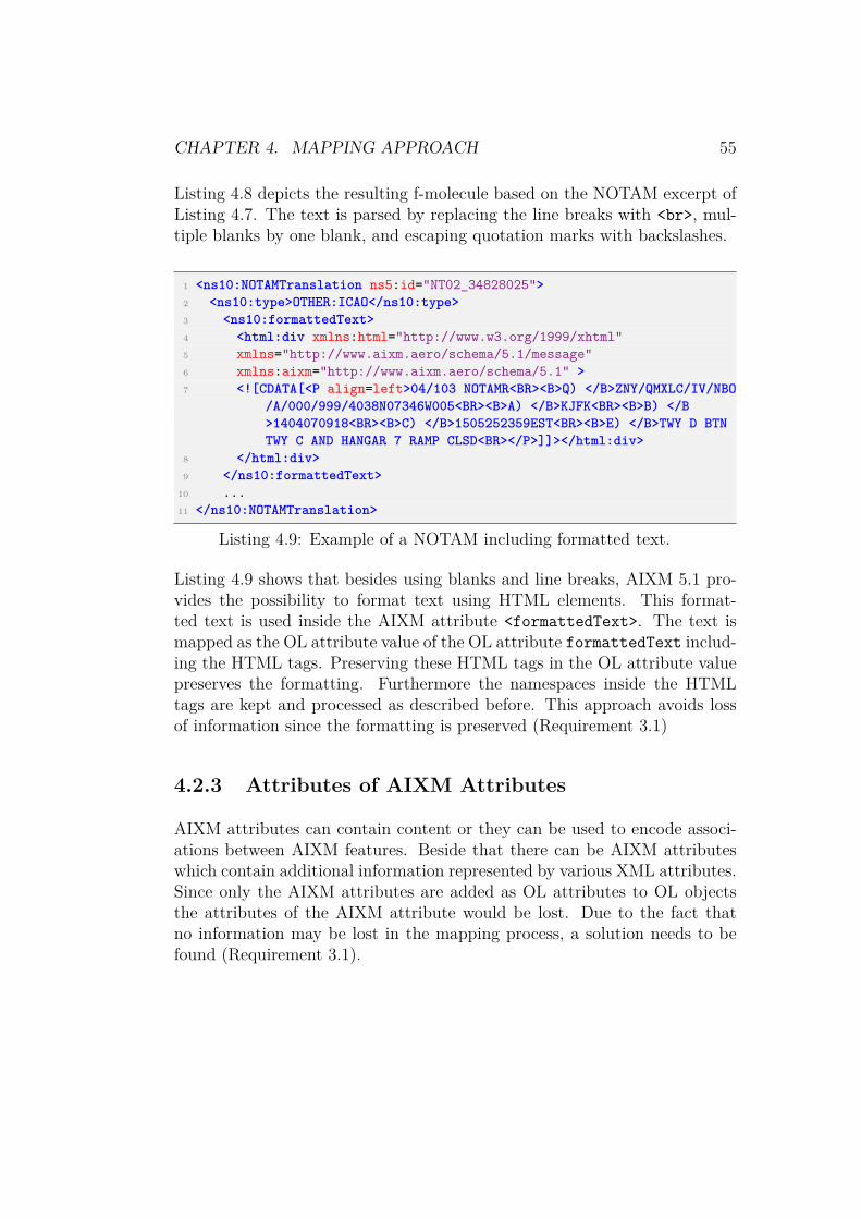
CHAPTER 4. MAPPING APPROACH 55
Listing 4.8 depicts the resulting f-molecule based on the NOTAM excerpt ofListing 4.7. The text is parsed by replacing the line breaks with <br>, mul-tiple blanks by one blank, and escaping quotation marks with backslashes.
1 <ns10:NOTAMTranslation ns5:id="NT02_34828025">2 <ns10:type>OTHER:ICAO</ns10:type>3 <ns10:formattedText>4 <html:div xmlns:html="http://www.w3.org/1999/xhtml"5 xmlns="http://www.aixm.aero/schema/5.1/message"6 xmlns:aixm="http://www.aixm.aero/schema/5.1" >7 <![CDATA[<P align=left>04/103 NOTAMR<BR><B>Q) </B>ZNY/QMXLC/IV/NBO
/A/000/999/4038N07346W005<BR><B>A) </B>KJFK<BR><B>B) </B>1404070918<BR><B>C) </B>1505252359EST<BR><B>E) </B>TWY D BTNTWY C AND HANGAR 7 RAMP CLSD<BR></P>]]></html:div>
8 </html:div>9 </ns10:formattedText>
10 ...11 </ns10:NOTAMTranslation>
Listing 4.9: Example of a NOTAM including formatted text.
Listing 4.9 shows that besides using blanks and line breaks, AIXM 5.1 pro-vides the possibility to format text using HTML elements. This format-ted text is used inside the AIXM attribute <formattedText>. The text ismapped as the OL attribute value of the OL attribute formattedText includ-ing the HTML tags. Preserving these HTML tags in the OL attribute valuepreserves the formatting. Furthermore the namespaces inside the HTMLtags are kept and processed as described before. This approach avoids lossof information since the formatting is preserved (Requirement 3.1)
4.2.3 Attributes of AIXM Attributes
AIXM attributes can contain content or they can be used to encode associ-ations between AIXM features. Beside that there can be AIXM attributeswhich contain additional information represented by various XML attributes.Since only the AIXM attributes are added as OL attributes to OL objectsthe attributes of the AIXM attribute would be lost. Due to the fact thatno information may be lost in the mapping process, a solution needs to befound (Requirement 3.1).

CHAPTER 4. MAPPING APPROACH 56
1 <ns5:TimePeriod ns5:id="Event_TS_TP_1_34828025">2 <ns5:beginPosition>2013-02-12T21:51:00.000Z</ns5:beginPosition>3 <ns5:endPosition indeterminatePosition="unknown" xsi:nil="true" xmlns
:xsi="http://www.w3.org/2001/XMLSchema-instance"/>4 </ns5:TimePeriod>
Listing 4.10: AIXM attribute with multiple attributes.
Listing 4.10 depicts the two AIXM attributes <ns5:beginPosition> and<ns5:endPosition>. Both represent OL attributes but the second onecontains additional XML attributes. A possible solution to map them tothe corresponding OL representation is to introduce a new OL object forAIXM attributes. AIXM attributes are added as f-molecules including theXML attributes as OL attributes. The upper OL object stores a referenceto the AIXM attribute by adding an OL attribute referring to it. In orderto refer to the attribute OL object an identifier is needed. The genera-tion of OL objects without an identifier is described in detail in Section 4.2.5.
1 Event_TS_TP_1_34828025:ns5#TimePeriod[ns#beginPosition -> "2013-02-12T21:51:00.000Z", ns5#endPosition ->uuid_b9024736_3a25_4c92_9b2f_bfc0e29ae31b].
2
3 uuid_b9024736_3a25_4c92_9b2f_bfc0e29ae31b:ns5#endPosition[indeterminatePosition -> "unknown", xsi#nil -> "true"].
Listing 4.11: Handling multiple XML attributes of AIXM attributes usingOL attribute objects.
As shown in Listing 4.11, the f-molecule representing an OL object is createdfor the AIXM attribute <ns5:endPosition> including its XML attributesas OL attributes. The AIXM attribute <ns5:beginPosition> is mapped asalready described in Section 4.1.
Another approach is to treat the AIXM attributes, which containmultiple XML attributes, as normal AIXM attributes. In order to preventinformation loss by not mapping the XML attributes of the AIXM attribute,they are included as OL attributes with a parameter in the parent OLobject. The parameter is named after the XML attribute name in the AIXMattribute. The XML attribute value is assigned to the OL attribute value.

CHAPTER 4. MAPPING APPROACH 57
1 Event_TS_TP_1_34828025:ns5#TimePeriod[ns#beginPosition -> "2013-02-12T21:51:00.000Z", ns5#endPosition(indeterminatePosition) -> "unknown", ns5#endPosition(xsi#nil) -> "true"].
Listing 4.12: Handling multiple AIXM attribute attributes with OLattributes including parameters.
Listing 4.12 depicts the mapping of XML attributes of an AIXM attributesby using OL attributes. As stated in Section 2.4 these OL attributes areactually methods which can receive a parameter. This parameter is thename of the XML attribute and the value is the one of the XML elementattributes. It is important to note that XML attributes of AIXM featuresare still added as OL attributes without parameters.
The second approach is chosen for the implementation since the firstapproach has drawbacks. The first approach provides a way to avoid lossof information, but it introduces overhead and conflicts with the basic ideawhere each AIXM attribute is added as an OL attribute. As depicted inListing 4.11, an overhead is introduced by the newly generated f-moleculefor the AIXM attribute. A reference to this f-molecule needs to be added inthe upper OL object and therefore an identifier is created. Furthermore thereadability of the generated OL program is negatively affected due to newlyadded lines containing f-molecules. In addition to that future work basedon the OL statements will have to interpret OL objects differently sincethey can represent "real" OL objects or OL objects representing attributes.Moreover, a new OL attribute must be defined to store text content sincethe name of AIXM attribute is already used as the OL class term.
4.2.4 Processing Timestamp
As defined in Requirement 3.5 the data sources need to be enriched byadditional information. This additional information includes a detectiontime stamp which records the time when the NOTAM has been mapped.The detection time stamp is used to find newly added or updated NOTAMs.To establish this, a new XML attribute detectionTimestamp is added tothe AIXM feature before it is mapped. During the processing this new XMLattribute of the AIXM feature is mapped and added as an OL attribute tothe OL object as depicted in Listing 4.13.

CHAPTER 4. MAPPING APPROACH 58
1 FNS_ID_3381098:ns13#AIXMBasicMessage[ns5#id->"FNS_ID_3381098", ns5#boundedBy(xsi#nil)->"true", ns13#hasMember->{Airport_1_3381098,Event_1_3381098}, detectionTimestamp->"2015-07-02T10:44:34.483Z"].
Listing 4.13: F-molecule of a NOTAM including a detection timestamp.
However it is more efficient to directly add the time stamp as an OL at-tribute value to the f-molecule of the NOTAM instead of manipulating theXML document and mapping it. The detection time stamp is added inthe following format "yyyy-MM-dd’T’HH:mm:ss.SSS’Z’" which correspondsto the date format of AIXM in order to ease later computational steps.
4.2.5 XML Elements with missing Identifiers
XML elements which are detected as OL objects need to have an identifier.As described in Section 4.1 this identifier is used as the id-term of theresulting f-molecule. XML elements which represent AIXM features usuallycontain an identifier. However there are cases where the identifier is notavailable (Requirement 4.2). For example when preprocessing steps addnew XML elements or create new OL objects they need to set an id-term.Therefore an identifier needs to be generated. As stated in Requirement 4.2the identifier must be unique and universal.
As mentioned in Section 2.3.5 AIXM relies on UUID as feature iden-tification. Therefore an UUID generator is used to create missing identifiers.The RFC 4122 defines the structure of an UUID (Leach et al., 2005). Theintention of UUID is to provide uniqueness across space and time. It is128 bits long and requires no central registration process. An automatedgeneration on demand can be done based on the fact that no centralizedauthority is required to administer them. UUIDs are represented in theircanonical form by a sequence of thirty-two hexadecimal digits. As depictedin Listing 4.14 these digits are grouped into a sequence of eight, four, four,four and twelve digits.
1 f81d4fae-7dec-11d0-a765-00a0c91e6bf6
Listing 4.14: Example of an UUID.
The formal definition is based on (Crocker & Overell, 2005) and follows theAugmented Backus-Naur Form (ABNF).
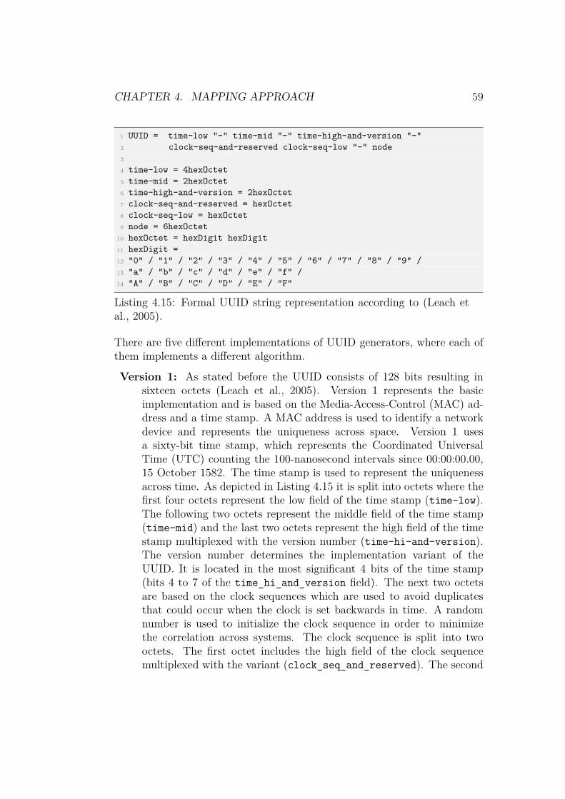
CHAPTER 4. MAPPING APPROACH 59
1 UUID = time-low "-" time-mid "-" time-high-and-version "-"2 clock-seq-and-reserved clock-seq-low "-" node3
4 time-low = 4hexOctet5 time-mid = 2hexOctet6 time-high-and-version = 2hexOctet7 clock-seq-and-reserved = hexOctet8 clock-seq-low = hexOctet9 node = 6hexOctet
10 hexOctet = hexDigit hexDigit11 hexDigit =12 "0" / "1" / "2" / "3" / "4" / "5" / "6" / "7" / "8" / "9" /13 "a" / "b" / "c" / "d" / "e" / "f" /14 "A" / "B" / "C" / "D" / "E" / "F"
Listing 4.15: Formal UUID string representation according to (Leach etal., 2005).
There are five different implementations of UUID generators, where each ofthem implements a different algorithm.
Version 1: As stated before the UUID consists of 128 bits resulting insixteen octets (Leach et al., 2005). Version 1 represents the basicimplementation and is based on the Media-Access-Control (MAC) ad-dress and a time stamp. A MAC address is used to identify a networkdevice and represents the uniqueness across space. Version 1 usesa sixty-bit time stamp, which represents the Coordinated UniversalTime (UTC) counting the 100-nanosecond intervals since 00:00:00.00,15 October 1582. The time stamp is used to represent the uniquenessacross time. As depicted in Listing 4.15 it is split into octets where thefirst four octets represent the low field of the time stamp (time-low).The following two octets represent the middle field of the time stamp(time-mid) and the last two octets represent the high field of the timestamp multiplexed with the version number (time-hi-and-version).The version number determines the implementation variant of theUUID. It is located in the most significant 4 bits of the time stamp(bits 4 to 7 of the time_hi_and_version field). The next two octetsare based on the clock sequences which are used to avoid duplicatesthat could occur when the clock is set backwards in time. A randomnumber is used to initialize the clock sequence in order to minimizethe correlation across systems. The clock sequence is split into twooctets. The first octet includes the high field of the clock sequencemultiplexed with the variant (clock_seq_and_reserved). The second

CHAPTER 4. MAPPING APPROACH 60
octet includes the low field of the clock sequence (clock_seq_low).The last six octets are used to store the host address respectively theMAC address of the network card. Systems without a MAC addresswill use a randomly generated value.
The chance of a collision in generated UUID in Verison 1 doesnot actually exist, due to the fact that it represents a single point inspace (computed using the MAC) and time (the number of intervals).Even if two UUIDs are generated in the same interval of nanosecondsthe time stamp will be incremented by one. This prevents collisionsin a reliable way. However, it was shown that collisions can occur.One use case which causes collisions is when the MAC is spoofed andthereby possibly not unique any more. Another way to cause collisionsis if UUIDs are generated on a device without a MAC address dueto a missing network card. Another drawback, besides the chanceof collisions, of this version is that it reveals the time when it isgenerated and the identity of the computer. Therefore other versionswere developed.
Version 2: The Version 2 is also known as the Distributed ComputingEnvironment (DCE) Security version (Leach et al., 2005). It is similarto Version 1 except that the first four octets of the time stamp arereplaced by the Portable Operating System Interface (POSIX) UserIdentifier (UID) of the user (The Open Group, 1997). Furthermorethe last octet of the clock sequence is replaced by a POSIX UIDdomain identifier. Due to this reduced clock size it is going to producecollisions sooner than Version 1.
Version 3 and 5: Both versions are based on generating UUIDs fromnames using hash functions (Leach et al., 2005). These names shouldbe unique such as textual names or namespaces. Therefore UniformResource Locators (URLs) or domain names are mostly used. Thegeneration algorithm has to generate always the same UUID basedon a given name in a namespace. Furthermore two UUIDs generatedfrom two different names in the same or different namespace shouldbe different. Version 3 uses the Message Digest 5 (MD5) Algorithmdefined in RFC 1321 (Rivest, 1992). The MD5 algorithm generatesa 128 bit hash output based on the given input which is truncatedto the 122 bits available in the UUID since six bits are reserved forfixed values. The use of MD5 in one system will probably lead tono collision but on a global scale it can lead to collision as shown in

CHAPTER 4. MAPPING APPROACH 61
(Selinger, 2006) and (Stevens, 2006). (Stevens, 2007) has shown, thatcollisions can occur after 233 invocations. The structure of Version 3differs because for the construction of the time stamp the MD5 hash ofthe given name is used instead of the interval of the nanoseconds. Alsothe clock sequence and the node are generated from the given name.Version 5 is similar to Version 3 except that for the generation thealgorithm Secure Hash Algorithm (SHA-1) is used (U.S. Departmentof Commerce & National Institute of Standards and Technology, 2012).The SHA-1 provides a 160 bit hash which is also truncated to 122 bit.As shown by (Rijmen & Oswald, 2005) a collision by obtaining SHA-1hashes from small messages can occur after 263 invocations. Genericalgorithms can obtain a collision after 280 invocations on average.
Version 4: UUID Version 4 relies on a random number (Leach et al., 2005).The first six bits are reserved, where the first four of them representthe version number. The remaining 122 bits are set using a randomnumber. That means that the sixty-bit value of the time stamp, thefourteen-bit value of the clock and the forty eight-bit value of the nodeare randomly generated.
As shown in (Suzuki, Tonien, Kurosawa, & Toyota, 2006), the birthdayparadox can be used to calculate the chance of a collision of two Version4 UUIDs. The birthday paradox shows that in contrast to the humanintuition a low number of randomly assigned people is needed to find apair with the same birthday date. This paradox can also be applied tothe probability of collisions within a randomly generated number basedon 122 bits. The chance is approximated using the formula p(n) ≈1 − e− n2
2x where the number of already generated UUIDs relates to 2n
and x is the number of bits occupied by the random number. TheTable 4.1 shows the resulting probabilities which result by applyingthe formula on the UUID generation.
After creating 1,12 quadrillion (250) UUIDs the probability of causinga collision while generating the next one is 1,1921 * 10−7.
Based on these insights of the different versions and their uniqueness adecision can be made. Version 1 can provide reliable UUIDs regardinguniqueness if the issues regarding the MAC spoofing and machines with noMAC address can be handled. However as long as this cannot be ensured,Version 1 and Version 2 cannot be used. Version 3 and Version 5 areboth based on hash functions which use names and namespaces in orderto generate a hash. As mentioned before, collisions can occur after 233

CHAPTER 4. MAPPING APPROACH 62
Table 4.1: Approximated probability of a collision after 2n UUID calculations
Calculates UUIDs (n) Collision Probability
240 = 1099511627776 1,1369 * 10−13
245 = 35184372088832 1,1641 * 10−10
250 = 1125899906842624 1,1921 * 10−7
255 = 36028797018963968 10−4
260 = 1152921504606846976 0,1175
265 = 36893488147419103232 0,9999
and 263 invocations. However, both are based on names and namespaceswhich again need to be distinguishable in order to create unique hashes.Therefore Version 4, which relies completely on random numbers, is preferred.
As shown in Listing 4.16 the AIXM UUID identifier consists of a pre-fix uuid which is append to the value of the id attribute. The Listing 4.16shows that the prefix uuid is set at the beginning of the identifiers’ value.
1 <aixm:SpecialNavigationStation gml:id="uuid.b9024736-3a25-4c92-9b2f-bfc0e29ae31b">
2 <gml:identifier codeSpace="urn:uuid:">3 b9024736-3a25-4c92-9b2f-bfc0e29ae31b4 </gml:identifier>5 <aixm:featureMetadata>6 <gmd:MD_Metadata>
Listing 4.16: UUID of an AIXM feature.
This format is kept in order to be consistent with other elements. In OLid-terms have to start with a character to be valid. Appending the uuidprefix prevents id-terms containing UUIDs to be invalid since UUIDs can begenerated starting with a number. Besides that, the hyphens in the UUIDneed to be replaced with underscores. In OL the hyphens are reserved sincethey are a part of the assignment "->" of OL attribute values to OL attributes.Moreover, the "." character is reserved in OL to declare the end of a statement.Therefore it is also replaced by an underscore as shown in Listing 4.17.

CHAPTER 4. MAPPING APPROACH 63
1 uuid.b9024736-3a25-4c92-9b2f-bfc0e29ae31b // invalid OL id-term2 uuid_b9024736_3a25_4c92_9b2f_bfc0e29ae31b // valid OL id-term
Listing 4.17: Invalid and valid OL id-terms.
The Listing 4.18 depicts an excerpt of an AIXM feature which is recognizedas an OL object element without an existing identifier.
1 <aixm:SpecialNavigationStation>2 <aixm:featureMetadata>3 <gmd:MD_Metadata>
Listing 4.18: AIXM feature without an identifier.
Therefore an identifier is generated using a UUID Version 4 generator. ThisUUID is manipulated by replacing all hyphens with underscores and addingthe uuid_ prefix in front of the UUID value. After this, the identifier isadded to the AIXM feature as an XML attribute. This XML attribute isthen mapped according to Section 4.2.3.
1 uuid_b9024736_3a25_4c92_9b2f_bfc0e29ae31b:aixm#SpecialNavigationStation[id->" uuid_b9024736_3a25_4c92_9b2f_bfc0e29ae31b", aixm#featureMetadata -> uuid_7ee612af_15a5_4468_807d_3c8ae33649c3].
2 uuid_7ee612af_15a5_4468_807d_3c8ae33649c3:gmd#MD_Metadata[id->"uuid_7ee612af_15a5_4468_807d_3c8ae33649c3"].
Listing 4.19: F-molecule including newly generated identifier for theAIXM features.
Listing 4.19 shows the resulting f-molecule including the newly generatedidentifiers. For both AIXM features SpecialNavigationStation and forthe sub AIXM feature MD_Metadata an identifier is generated.
4.2.6 Link Resolution
As stated in Requirement 3.2 local references inside an XML document mustbe resolved. Therefore the identifier of the referred XML element has to beused instead of the XLink reference statement. Section 2.3.5 describes thereferencing capabilities of AIXM. It is stated that AIXM provides internaland external references by using XLink. Internal references refer to existingXML elements inside the XML document.

CHAPTER 4. MAPPING APPROACH 64
As shown in Listing 4.20 line twelve, the XML element with the iden-tifier Event_1_3246418 is being referred. Therefore the locator attributehref is used which allows an XLink application to find a remote or localeresource. However, the locator attribute xlink:href can only identify aresource which represents an XML document. To refer to a specific XMLelement the XML Pointer Language (xPointer) is used. An XPointer allowsto link to a specific fragment of an XML document by using XML PathLanguage (xPath) expressions. Therefore the "#"-sign, which indicates thatthe local XML document represents the resource, followed by the targetidentifier is used.
1 <ns13:AIXMBasicMessage ns5:id="FNS_ID_32464181">2 ...3 <ns13:hasMember>4 <ns6:AirportHeliport ns5:id="Airport_1_3246418">5 <ns5:boundedBy xmlns:xsi="http://www.w3.org/2001/XMLSchema-
instance" xsi:nil="true"/>6 <ns6:timeSlice>7 <ns6:AirportHeliportTimeSlice ns5:id="Airport_TS_1_3246418">8 ...9 <ns6:extension>
10 <ns10:AirportHeliportExtension ns5:id="AHE_EVENT_1_3246418">11 <!-- Reference to other AIXM XML feature -->12 <ns10:theEvent xmlns:ns2="http://www.w3.org/1999/xlink"
ns2:href="#Event_1_3246418"/>13 </ns10:AirportHeliportExtension>14 </ns6:extension>15 </ns6:AirportHeliportTimeSlice>16 </ns6:timeSlice>17 </ns6:AirportHeliport>18 </ns13:hasMember>19 <ns13:hasMember>20 <ns10:Event ns5:id="Event_1_3246418" xmlns:ns10="http://www.aixm.
aero/schema/5.1/event">21 ...22 </ns10:Event>23 </ns13:hasMember>24 </ns13:AIXMBasicMessage>
Listing 4.20: Local reference within an XML document and the XLinktarget.
The reference in Listing 4.20 is mapped according to Section 4.2.3 since itis detected as an XML attribute of an XML element representing an OLattribute. The mapping output of this is depicted in Listing 4.21.

CHAPTER 4. MAPPING APPROACH 65
1 AHE_EVENT_1_3246418:ns10#AirportHeliportExtension[ns5#id="AHE_EVENT_1_3246418", ns10#theEvent(ns2#href)->"#Event_1_34058787"].
Listing 4.21: Mapping of references as XML attributes of AIXMattributes.
However, the reference value is not resolved since it is still treated as a literalinstead as an id-term. The mapping described in Section 4.2.3 needs to beadapted for links. Instead of referring to the OL object identifier literal, theOL attribute refers directly to the OL object. In order to distinguish localfrom external references the parameter ns2#href respectively xlink#href isreplaced by ref (Listing 4.22). This makes it easier to detect local referencesin the OL representation.
1 AHE_EVENT_1_3246418:ns10#AirportHeliportExtension[ns5#id="AHE_EVENT_1_3246418", ns10#theEvent(ref)->Event_1_34058787].
Listing 4.22: Mapping of resolved references.
Beside local references, AIXM supports concrete external references whereinformation about referred AIXM features is available via web services.Again XLink in combination with XPointer is used to refer to theseresources. Instead of providing just the identifier of the referred XMLelement, an URL is additionally used. The URL will be resolved to an XMLdocument which contains the XML element which is referred using a "#"and the identifier (Listing 4.23).
1 <aixm:clientAirspace ns5:id="CA_1_3246418" xlink:href="http://aim.faa.gov/services/AirspaceService#uuid.a82b3fc9-4aa4-4e67-8def-aaea1ac595j"/>
2
3 <aixm:clientAirspace ns5:id="CA_1_3246418"4 xlink:href="http://aim.faa.gov/services/AirspaceService?get=a82b3fc9-4
aa4-4e67-8defaaea1ac595j#xmlns(ns1=http://www.opengis.net/gml/3.2)xmlns(ns2=http://www.aixm.aero/schema/5.1)xpointer(//ns2:Airspace[ns1:identifier=’a82b3fc9-4aa4-4e67-8def-aaea1ac595j’])"/>
Listing 4.23: Simple and complex remote XLink statement with anXPointer reference.
Both references in Listing 4.23 refer to the same XML element. The firstreference uses a simple XLink syntax whereas the second one defines thereference in a more detailed way. However since both are external references

CHAPTER 4. MAPPING APPROACH 66
they are not resolved during the mapping. Both are mapped according toSection 4.2.3 since they are detected as XML attributes of an XML elementrepresenting an OL attribute.
4.2.7 Bounding Boxes
Requirement 4.1 defines that the missing bounding box for NOTAMs hasto be calculated and added to the NOTAM and its features. A boundingbox represents the minimum rectangle which is oriented to the x- andy-axes in order to enclose a geographic feature of a geographic dataset(Caldwell, 2005). It is also known as Minimum Bounding Rectangle (MBR)or envelope. As depicted in Figure 4.1, the bounding box is specified bytwo geographic coordinates which define the minimum x- and y-value andthe maximum x- and y-value. The coordinates are determined by twolongitudes and two latitudes representing the western-most, eastern-most,northern-most and southern most limits.
Figure 4.1: Geographic coordinates of the bounding box of the JFK Airport.
There exist several other bounding container shapes beside bounding boxes

CHAPTER 4. MAPPING APPROACH 67
such as bounding parallelograms, circles, balls or ellipses (Caldwell, 2005).The bounding box is the simplest bounding container and requires the leastcomputational effort which is why it is mostly used. Due to the low computa-tional effort it is used in many geometry applications for collision avoidance,ray tracing or hidden object detection. Moreover it is used for spatial indexschemes which use them to subdivide space. In the SemNOTAM system it isused to detect overlaps in order to find relevant NOTAMs for a given GMLshape.
Figure 4.2: Visualization of a GML envelope.
In GML the bounding box is encoded as the Envelope XML element (Cox,Daisey, Lake, Portele, & Whiteside, 2005, p. 59). As depicted in Figure 4.2an envelope determines the area "by using a pair of positions definingopposite corners in arbitrary dimensions". The north-east coordinatedetermines the upperCorner and the south-west coordinate determines thelowerCorner of the GML envelope (Listing 4.24). Moreover, the XMLelement is associated to an XML element which represents an AIXM featureby the AIXM attribute <gml:boundedBy>. As stated in Requirement 4.1the bounding box respectively the GML envelope has to be calculated forthe NOTAM as well as the AIXM features within it. This has to be donewhen no bounding box exists but a geographic data is available.

CHAPTER 4. MAPPING APPROACH 68
1 <gml:boundedBy>2 <gml:Envelope srsName="urn:ogc:def:crs:EPSG::4326">3 <gml:lowerCorner>-32.0886111111111 -47.0</gml:lowerCorner>4 <gml:upperCorner>57.690815969999996 52.4283333333333</gml:
upperCorner>5 </gml:Envelope>6 </gml:boundedBy>
Listing 4.24: Example of an XML GML envelope.
Since bounding boxes are used to enclose geographical datasets, they haveto capture two use cases. The first one is a dataset containing multiplegeographic points which can represent various GML shapes. The second usecase is a dataset with only one geographic point in it. The bounding boxdepicted in Figure 4.2 represents a dataset containing multiple geographicpoints representing a so called linear ring. It depicts the path of a runway ofthe John F. Kennedy International Airport. In order to calculate the bound-ing box the western-most, eastern-most, northern-most and southern-mostpoints of the dataset need to be determined. Therefore the coordinates of thepoints need to be compared. The northern-most point is characterized by themaximum latitude value whereas the southern-most point is determined bythe minimum latitude. Similar to this the western-most point is determinedby the point with the minimal longitude value whereas the eastern-most isdetermined by the maximal longitude value of a point.
However, the bounding box calculation for one geographic point in adataset is more complex. To calculate a bounding box for a single point,additional information such as the radius of the bounding box is needed.As depicted in Figure 4.3 the radius is used to determine the distance fromthe given GML point to the points which are needed to calculated the GMLenvelope. The center point is the given GML point for an AIXM featuresuch as the airport reference point of an airport. It represents the centerof the circle which is used to determine the western-most, eastern-most,northern-most and southern-most points. These points can be determinedby using the Harversine Formula which assumes that the earths’ surface canbe represented by a sphere (United States Census Bureau, 1997). Specifyingthe azimuth (angle) and distance (radius) from a given point, a new onecan be calculated. Another algorithm for calculating points is representedin (Vincenty, 1975). In contrast ot the Harversine Formula this algorithmassumes that the earths’ surface is an ellipsoid. Since the earths shape ismore similar to an ellipsoid than to a sphere the algorithm of Vincenty(1975) leads to more accurate results.

CHAPTER 4. MAPPING APPROACH 69
After the points are calculated they can be used to determine the
Figure 4.3: Bounding box calculation for one geographic point.
upper and lower corner of the bounding box as depicted in Figure 4.3. Thelatitude of the north-point and the longitude of the east-point determinethe upper corner. The latitude of the south-point and the longitude of thewest-point determine the lower corner. The calculated corners are thenadded in the XML document as a GML envelope as depicted in Listing 4.24.Since this is a preprocessing step it is added to the XML document insteadof adding it directly to the mapped f-molecule.
As mentioned before, a NOTAM can contain multiple features whichcan contain GML points and therefore may require a bounding box calcula-tion. Beside this, each NOTAM has its own bounding box. This boundingbox of the NOTAM is the outer one which encloses all GML points includedin the features’ bounding boxes. For the calculation of the NOTAMs’bounding box all GML points of all features must be considered. However itis easier to access the already calculated bounding boxes and use the cornerpoints for the calculation of the outer bounding box. It is not necessary toaccess all GML points again after the bounding boxes for the NOTAMs’features were calculated.

CHAPTER 4. MAPPING APPROACH 70
As stated in Section 3.3 the interpretation of GML information espe-cially the coordinates depends on the given CRS. CRSs are required dueto the distortions which occur during the plotting of the earths surfaceonto a 2D map. CRSs define how the earths surface can be mapped tolatitude and longitude coordinates and how this mapping can be projectedon a map (Frazier, 2013). As mentioned before, the earths’ shape can bemodeled using a sphere or an ellipsoid. An ellipsoid shape is preferredsince the earth is slightly distorted at the equator. Datums are defined toanchor the abstract coordinates to the earth. They specify an origin pointof the coordinate axes and their direction resulting in a 3D ellipse or spherewith latitude and longitude coordinates. Multiple projections such as acone, plane, or cylindrical one can be used to represent the 3D globe to a2D map representation. Figure 4.4 depicts a cylindrical projection of theearths surface. As shown the projection of the surfaces causes distortions.Especially the area at the top and the bottom of the projection is distorted.Angles and distances are preserved. Due to the occurring distortions otherprojections are used depending on which distortion should be minimized.As shown in Listing 4.24 the CRS is encoded in the attribute srsName. ThissrsName needs to be resolved to find the corresponding CRS. Due to thedifferent projections the interpretations of the given coordinates depends onthe CRS.
Figure 4.4: Cylindrical projection of the earths surface1.
Since NOTAMs can include GML datasets of worldwide locations it is possi-ble that different CRSs are used to encode the data. Therefore the datasetsneed to be transformed to a common CRS in oder to align them with each
CHAPTER 4. MAPPING APPROACH 71
other. This transformation ensures that the units are interpreted the sameway.
4.3 Mapping Technologies
The mapping of the structured data sources to the corresponding OLrepresentation is the central task of the mapper. It is needed to fulfillthe Requirement 2.1, Requirement 2.2, and Requirement 2.3. Thereforea suitable technology must be found. This section provides an overviewof existing transformation technologies for mapping XML documents.Each technology is analyzed and a prototype of the mapper is imple-mented with it. The prototype includes all basic steps excluding thepreprocessing step such as the GML handling. However, the preprocessingsteps have to be considered while selecting the technology. Finally theimplementations are compared and the best performing technology is chosen.
As mentioned before, the technologies represent transformation tech-nologies for mapping XML documents. Compiling technologies are notevaluated since the mapping task differs from a compiling task. Compilingcovers the transformation of a source code written in programming languageinto another programming or computer language (Aho & Ullman, 1972,p. 59 ff.). It is mostly used to transform source code from a high-levelprogramming language (source language) to a lower level programminglanguage (target language). The source code written in the source languagerepresents a string of characters which is converted by a compiler to objectcode. The compilation task is split into two phases. The analysis phase isused to analyze the lexical structure in order to retrieve lexical units calledtokens. Tokens can represent keywords, strings, operators or numbers.Moreover, the syntax analysis checks whether the source code correspondsto the predefined syntax respectively grammar of the source programminglanguage. The semantic analysis checks whether the source code followspredefined rules. Examples for such rules can be that a variable must bedeclared before it is used or that only a value of the corresponding type mustassigned to it. The result of the first phase is a decorated syntax tree. Afterthe analysis phase is finished, the second phase starts. This generation phaseuses the decorated syntax tree and creates programming code of the targetlanguage which is optimized according to data-flow and dependence analyses.
1https://commons.wikimedia.org/wiki/File:Usgs_map_miller_cylindrical.PNG

CHAPTER 4. MAPPING APPROACH 72
In contrast to that, the mapping task does not transform a sourceprogramming language into a target programming language. It transformsXML, which is a markup language for documents, into the knowledge-representation language OL. There is no programming source code whichwill mapped to a target programming language. However, the basic idea ofcompiling can be applied. In the analysis phase the bit sequence representingthe XML document must be converted to a character sequence which canbe used for lexical analysis (Lam, Ding, & Liu, 2008). The result of this aretokens such as start/end XML elements, attributes names and values, andtext. The syntax and the semantic of the data sources are predefined bythe XML syntax and their corresponding XSD documents. As mentionedin Section 2.3.1 the XML syntax determines the well-formedness and theXSD document determines the validity. The result of the first phase is amodel representing a tree or events depending on the used XML technology.The model is used in the second phase in order to map it to OL statementsrepresenting OL objects and attributes. Since f-molecules are used insteadof single F-atoms and data-F-atoms an optimization is performed. Besidesthat the source representation is enriched by additional information orhandling missing information.
In order to map XML documents to OL statements the technologiesmust provide the possibility to access the XML document structure and de-fine transformation rules. The accessing of the XML document correspondsto the analysis phase which is supported by various XML parsers. Numerousprocessing technologies which support the parsing of XML documents canbe found. XSLT, XQuery, and directly using XML parsers such as SAX,StAX, and DOM are the most common ones. The following subsections willanalyze each of them.
4.3.1 XSLT
XSLT is a part of the Extensible Styling Language (XSL) which wasdeveloped to perform complex styling operations on XML documents (Lamet al., 2008). In contrast to Cascading Style Sheets (CSS), which are usedto format HTML, the XSL styling sheets use an XML notation in order toformat XML documents. Every XSLT stylesheet is a valid XML documentsince it follows the XML notation. Beside the formating capabilities of XSL,XSLT allows to transform XML documents by applying XSLT stylesheetsto other XML documents, HTML pages, plain text, or other representations

CHAPTER 4. MAPPING APPROACH 73
(W3C, 2007). XPath is included as a subset of XSLT and is primarily usedto identify subsets of the XML document tree. Beside that it can be usedto perform calculations. XPath also provides various functions which enrichthe restricted capabilities of XSLT.
The data model which is used in XSLT is the XQuery and XPathdata model (XDM) (IBM, 2010). XDM represents the content of an XMLdocument as a tree structure. This tree structure is described using a se-quence of items. An item is either an atomic value or a node. Atomic valuesare represented by the built-in atomic data types defined in the XML Schemasuch as strings, dates or integers. Nodes are characterized by propertieswhich indicate its name, attributes, parent, children or other information.There are seven different kinds of nodes which are supported by XDM.Each kind indicates whether the node is a document, attribute, element,text node, processing instruction, or namespace. Moreover the XDM storesthe node identity and the hierarchy of the document and therefore each node.
XSLT is based on pattern-matches and templates. The pattern-matches aredetermined by XPath expressions selecting specific elements of the XDM.A template contains rules which are triggered when a pattern-match isdetected. The template defines the transformation and the output. Further-more advanced processing steps can be executed. XSLT allows to define andread variables, however they cannot be altered after they are bound (DeSchrijver, De Neve, Van Deursen, De Cock, & de Walle, 2006). Besides thatit allows to define control flows providing choices or loops. These controlflow elements again use XPath expressions. Moreover, templates can bereused and therefore used to modularize the XSLT stylesheet.
Figure 4.5 depicts the XSLT transformation process. One or more XML doc-uments and one or more XSLT stylesheets can be used as input files. TheXSLT processor starts with reading and preparing the XSLT stylesheets.After that the processor builds a source tree based on the given XML doc-uments. The built source tree is processed by finding the best-matchingtemplate for a given XML node. When the template is identified it is in-stantiated and recursively applied to the XML node in the source tree. Theresult is either the creation of a node in the result tree or the processing ofother nodes in the source tree. Finally, after the XSLT processor finishedthe processing of the source tree and the applying of XSLT templates theresulting result tree is output.

CHAPTER 4. MAPPING APPROACH 74
Figure 4.5: XSLT transformation process (W3C, 2007).
XSLT Prototype Implementation: XSLT allows to implement aprototype which covers main features of the mapping concept as depictedin Listing B.1. However there is a huge drawback of this solution. Therecursive approach cannot be applied easily since the XSLT processordirectly creates an output. The recursive approach would result in nestedf-molecules. However, the recursion is needed to iterate through the XMLtree representing the source data. The problem is that XML elementsexist which have no identifier. For these XML elements an identifieraccording to Section 2.4 needs to be generated. As stated in Section 4.1this identifier is used in the OL f-molecule of an XML feature elementas an OL attribute value in order to store the associations to other OLobjects. However this identifier needs to be passed recursively to sub XML el-ements which use this identifier as the id-term for the mapped OL f-molecule.
This issue can be overcome by changing the recursion to an end re-cursive approach. However, this cannot be easily established in XSLTstylesheets since variables cannot be reassigned to new values and noadditional data model can be defined within the scope of XSLT. Moreoverit is not trivial to return the output as the return value of a templatewithout directly outputting it. Another solution would be to preprocessthe whole XML input document and add missing identifiers before it istransformed with XSLT. However, other preprocessing steps such as theGML handling must be conducted before in order to prevent XML elementswithout identifiers.

CHAPTER 4. MAPPING APPROACH 75
This shows that the implementation is possible but it would result incomplex and hardly maintainable XSLT stylesheets. In contrast to theXQuery and DOM approach the XSLT implementation would not al-low to easily extend the existing implementation which contradicts theRequirement 3.3.
4.3.2 XQuery and BaseX
XQuery is a functional programming and query language used for queryingand transforming data (W3C, 2014). The accessed data is usually rep-resented as XML documents, but other data formats such as plain text,relational database, or JavaScript Object Notation (JSON) can be accessedusing extensions. Similar to XSLT, XPath is a subset of XQuery. BothXSLT and XQuery are developed by the World Wide Web Consortium(W3C) which is also responsible for XPath. Moreover, XSLT and XQueryshare the same data model XDM which is described in Section 4.3.1.XQuery allows to select documents and elements regarding their content,attributes, or structure. Moreover it allows to merge sequences of elementsto new elements.
Since XQuery was initially developed to provide a query language forXML databases it is inspired by Structured Query Language (SQL) whichis used to query relational databases (W3C, 2014). XQuery providesFLWOR expressions which are similar to the SELECT statements of SQL.FLWOR expressions allow to bind variables, iterate through sequences,and to define pattern for the result. A FLWOR expressions consists ofthe five clauses FOR, LET, WHERE, ORDER BY, RETURN. However avalid FLWOR expression does not need to contain all of them. The FORclause is used to iterate through sequences. Moreover it can be used tojoin them in order to create a Cartesian product. A FOR clause is alwaysreturning a sequence using the RETURN clause. The ORDER BY clauseallows to sort the items within the sequence in an ascending or descendingmanner. In order to filter the returned items of the sequence it is possibleto define WHERE clauses which check whether a logical expression isfulfilled by the item or not. Beside FLWOR expressions, XQuery providesthe possibility to union, intersect, or except sequences. Aggregate andarithmetic functions are also supported as well as control flow clauses. Itis important to note that FLWOR expression can be nested within eachother. Moreover variables can be bound to the returned sequence. In orderto modularize the queries it is possible to define own or use existing functions.

CHAPTER 4. MAPPING APPROACH 76
1 (: query all notams encoded as AIXMBasicMessages :)2 let $notams := (3 for $element in doc($db)//* where local-name($element) = "
AIXMBasicMessage" order by xs:date($element/@detectionTimestamp)descending
4 return $element5 )
Listing 4.25: Example of a FLWOR expression.
Listing 4.25 depicts a FLWOR expression which returns a sequence whichcontains XML nodes with the local name AIXMBasicMessage. Moreoverthe sequence is ordered by the attribute value detectionTimestamp in adescending manner and bound to the variable $notams.
XQuery can be used to directly access single XML documents. How-ever, usually XQuery is used to query collections of XML documents. Asdepicted in Figure 4.6 an XML database is used to store XML documentcollections. Besides the storing of multiple XML documents an XMLdatabase allows to use index techniques which increase the performance.The indexed collections can then be accessed by an XQuery engine whichresolves the query formulated using FLWOR expressions. The retrievedsequence is returned as the query result.
Figure 4.6: XQuery querying and transformation process (W3C, 2014).

CHAPTER 4. MAPPING APPROACH 77
Popular XML databases amongst others are eXistDB2, BaseX3, and Mark-Logic4. For the prototype implementation the BaseX XML database is se-lected due to fact that it provides an XPath and XQuery 3.1 processor andtherefore supports the latest version of XQuery. Furthermore BaseX pro-vides an easy to use and interactive Graphical User Interface (GUI) frontend(BaseX, 2015). Structural indexes such as name, path, or resource indexescan be created. Moreover, value indexes are also supported which allow toindex attributes, text and full-text.
XQuery Prototype Implementation: The XQuery prototype imple-mentation is depicted in Listing B.2. Since XQuery and XSLT use the samedata model both face the same problems which occurs using recursion. Theoutcome of the XQuery results in nested OL f-molecules. However, XQueryallows to implement an alternative solution using an end recursive approach.The reason for this can be found in the FLWOR expressions which can easilybe used to retrieve sequences of items without outputting them directly.This fact is crucial since it allows to return sequences to outer FLWORexpressions. Especially when missing identifiers are generated they can beused as a value of the association while still being able to return them toouter FLWOR expression. The outer-most FLWOR expression returns allthe sequences which are then used to start the end recursion.
The basic idea of the XQuery prototype implementation is to create asequence which contains the mapped f-molecules represented as elementsand text. Later it is mapped to a textual representation of the f-molecules.The sequence is returned by the end recursion which returns all f-moleculesequences of AIXM features. The first step is to retrieve all NOTAMelements stored in the BaseX database (Listing B.2). The implementationretrieves only the NOTAM data sources since the other two data sourcescan be mapped the in the same way. These NOTAM elements representthe first level of the hierarchy. They are parsed at first by calling the parsefunction using an empty identifier and an element as input parameter. Anempty identifier indicates that no identifier was generated and thereforethe identifier of the XML id attribute should be used. Instead of directlymapping the element to a textual representation a sequence containing theXML element <fmol> is created. This sequence contains the id-term, the OLclass, the attributes of the element, and the children of the element. These
2http://exist-db.org/exist/apps/homepage/index.html3http://basex.org/4http://marklogic.com
CHAPTER 4. MAPPING APPROACH 78
child elements represent AIXM attributes which either include text contentor represent an associations to other AIXM features. The child elementsare looped and for each of them the attribute name, its attributes, thecontent, and, most important, the associated AIXM features are stored inXML elements. The associated AIXM features are stored in the <toParse>element because they represent the children of the AIXM attribute. Sincethe identifier of them is used later as the value of an OL attribute it isdetermined and added to the sequence as the element <subobjid>. Besidesthat the associated AIXM feature is stored in the element <subobjname>.After the sequence containing the f-molecule element is build it is returned.This sequence contains all F-atoms and data-F-atoms of the f-moleculeencoded as elements. However up to now no recursion was started. Therecursion starts when the f-molecules of the associated AIXM features areparsed. All these AIXM features are stored in the <toParse> element of thealready parsed NOTAMs. Therefore all elements in the <toParse> elementare iterated and for each of them the parse function is called. The value ofthe <subobjid> is used as the id parameter and the <subobjname> elementis used as the element parameter. Again a sequence containing the <fmol>element is build as described above but this time the given parameter is usedas the id-term. After the sequence is build the recursion is started by callingthe parse function for all elements which are included in the <toParse>element of the newly parsed <fmol> element. When the end recursion isfinished all sequences are returned. Since the element <subobjname> is notneeded anymore it is removed from the sequences. Afterwards the stringswithin the sequences are joined and the outcome is combined and returned.
4.3.3 SAX and StAX Parser
SAX and StAX parser are used to efficiently parse huge XML documents.They do not create a tree structure like in XDM used by XQuery and XSLT.Instead of building a whole XML document tree, events are created andfired while performing the lexical analysis (Lam et al., 2008) (Megginson,2001). Which means that SAX and StAX do not conduct the whole analysisphase, both stop after lexical analysis. As mentioned before the result ofthe lexical analysis are tokens such as start/end XML elements, attributenames and values, and text. Whenever a token is recognized by the SAX orStAX parser an event is fired in order to notify the accessing application.This allows to access partial data before the parsing of the whole XMLdocument is complete. After the event is fired, the token and the event aredestroyed which prevents a growing memory usage while parsing the entire

CHAPTER 4. MAPPING APPROACH 79
XML document. SAX and StAX parsers allow a memory efficient usagein contrast to XSLT and XQuery where the whole XML document tree isstored within the memory.
As depicted in Figure 4.7 SAX implements the so called push model(Lam et al., 2008). Whenever an event is fired, due to a detection of a token,the corresponding callback function is invoked. To invoke the correspondingcallback function the application must provide an event handler which isregistered to the parser. The callback functions determine how the eventwill be handled. They need to be defined in the accessing application. TheSAX parser loops through the entire XML document and continuouslychecks which token is produced from the lexical analysis in order to fire thecorresponding event and invoke thereby the corresponding callback function.
Figure 4.7: SAX push parsing approach (Lam et al., 2008).
In contrast to the push model of the SAX parser, the StAX parser is based onthe so called pull model (Figure 4.8). Instead of continuously firing eventsand invoking the corresponding callback functions, the StAX parser waitsuntil the application invokes the lexical analysis of the next token. Thetoken is then parsed and the corresponding event is fired. This allows theapplication to skip uninterested events, in contrast to the SAX parser whereall events must be handled.
Figure 4.8: StAX pull parsing approach (Lam et al., 2008).
As indicated in Figure 4.7 and Figure 4.8 the transformation of the detected

CHAPTER 4. MAPPING APPROACH 80
tokens must be handled by the application. Since both only provide accessto the parsed tokens, no transformation, query or selection possibilities aregiven. The drawback of SAX and StAX is that XPath is not supported sinceno XML tree is available.
SAX and StAX Prototype Implementation: Due to the drawbackthat the SAX as well as the StAX parser do not provide the capability ofdirectly selecting specific XML elements a prototype is not implemented. Inorder to apply the concepts introduced in Section 4.1 and Section 4.2 thecapability to select specific elements is crucial. Especially the link resolutiondepends on this feature. Even if the link resolution can be implementedwith a workaround the GML handling requires the selection capabilities.Without it the GML elements of the AIXM features cannot be selected whichare needed in order to conduct the bounding box calculation described inSection 4.2.7.
4.3.4 DOM Parser
"The DOM is a platform- and language-neutral interface that will allowprograms and scripts to dynamically access and update the content, struc-ture and style of documents" (W3C, 2009). It is an API for HTML andXML documents which specifies the logical structure of documents as acollection of objects. Moreover, it describes how they can be accessed andmanipulated. DOM is an object model specifying interfaces; it is not a setof data structures. Relationships such as the child or parent relationship aredefined by logical relationships which are defined by the API. DOM can beused as a basis for implementing XML applications which process an XMLdocument as if it were a tree.
Parsers implementing DOM can be used to represent and interact withobjects in XML, HTML, or XHTML documents. In contrast to SAX andStAX parsers a DOM parser conducts the whole analysis phase returningan XML tree structure. This tree structure can be accessed using XPathexpressions. Therefore the XML DOM parser provides methods to traversethe tree structure, access it, and insert new, or delete existing nodes withinit. Moreover, the hierarchical structure of the XML document is preserved.Similar to XDM, DOM stores the whole tree structure in the memory whichis why it is not as well performing as SAX or StAX parsers.

CHAPTER 4. MAPPING APPROACH 81
Figure 4.9: DOM parsing approach (Lam et al., 2008).
Figure 4.9 depicts the DOM parsing process. The DOM parser accesses theXML document and loops through it. While looping through it the lexicalanalysis detects tokens which are added to the construction of the tree. Afterthe XML document is completely iterated and the data structure is finished,it is returned to the application. The application can then access the DOMtree model and navigate through it using XPath expressions. However, theDOM parser only provides access to the XML document without providingtransformation or query capabilities.
DOM Prototype Implementation: Similar to SAX and StAX theapplication needs to implement the mapping task since no transformation orquery capabilities are provided. An object-orientated programming languageis chosen for the application because a DOM XML parser represents theXML document as an object collection structured as a tree. Besides thefact that no transformation or query capabilities are provided, no additionaldata structures are provided by the DOM parser. Therefore the applicationneeds to build an appropriate data structure where the parsed elementsand their content can be stored. However, this allows to fully adapt theimplementation according to the requirements.
The prototype implementation is depicted in Listing B.3. However,Listing B.3 is not providing the whole source code, it shows the core of theparser. As mentioned before the application needs to create a data modelto store the mapped data. The data structure consists of an OLProgramclass which contains multiple OLNamespaces and OLFMolecules. TheOLFMolecules store its namespace, the OLClass and the OLAttributeswhich are represented by OLObjects. An OLObject is an abstract superclass of OLLiteral and OLLink. This data structure is filled during themapping task. The prototype starts with building an XML DOM treebased on a given input XML document. The root element is selected and

CHAPTER 4. MAPPING APPROACH 82
the mapping is started by calling the parseNode()-method assigning thedocument, the root element, the hierarchy level zero and the name of theroot element as the parent name to it. In the method the level is updatedby checking if the parent has changed. When the parent has changed thelevel is increased and the parent is updated to the new one. After the levelis updated it is checked whether the element represents an XML node sinceonly XML nodes can be either an AIXM feature or an AIXM attribute. Dueto the fact that AIXM features and AIXM attributes are alternating theelement type is determined using a modulo-2-operation.
When an AIXM feature is encountered a new f-molecule is instanti-ated, initialized and assigned to the OLProgram. For each of the childelements of the AIXM feature the parseNode()-method is called startingthe recursion. It stops when no child elements exists. When the modulo-2-operation encounters an AIXM attribute it is added to the parent f-moleculeas an OL attribute. The value of this OL attribute is either text orrepresenting an association to another AIXM feature. If it is an associationthe identifier of the associated AIXM feature is determined and added as theOL attribute value of the parent f-molecule. Moreover the level is updatedand the parseNode()-method is invoked using the AIXM feature as a newinput parameter.
The recursion stops after there are no more AIXM attributes of AIXMfeatures or if there are no more child AIXM features of AIXM attributes.The filled data structure contains an OL program which includes allf-molecules and namespaces. These f-molecules and namespaces are iteratedand output according to their corresponding OL syntax.
4.3.5 Evaluation and Selection
This sections evaluates the implemented prototypes in oder to select the bestperforming technology for the concrete implementation of the mapping task.The evaluation of the prototypes is conducted by measuring the time whichis required to map a predefined number of NOTAMs to the correspondingOL representation. This will show how the prototypes perform whileincreasing the workload. The measurements are carried out on a computerwith an fifth generation Intel(R) Core(TM) i7-5500U processor and 8GBSingle Channel DDR3L 1600MHz RAM where one GB is directly assignedto the prototype application.
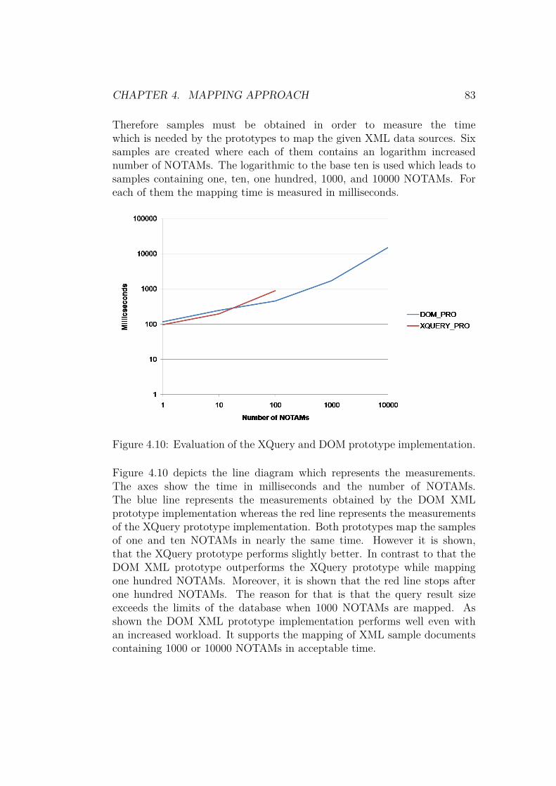
CHAPTER 4. MAPPING APPROACH 83
Therefore samples must be obtained in order to measure the timewhich is needed by the prototypes to map the given XML data sources. Sixsamples are created where each of them contains an logarithm increasednumber of NOTAMs. The logarithmic to the base ten is used which leads tosamples containing one, ten, one hundred, 1000, and 10000 NOTAMs. Foreach of them the mapping time is measured in milliseconds.
Figure 4.10: Evaluation of the XQuery and DOM prototype implementation.
Figure 4.10 depicts the line diagram which represents the measurements.The axes show the time in milliseconds and the number of NOTAMs.The blue line represents the measurements obtained by the DOM XMLprototype implementation whereas the red line represents the measurementsof the XQuery prototype implementation. Both prototypes map the samplesof one and ten NOTAMs in nearly the same time. However it is shown,that the XQuery prototype performs slightly better. In contrast to that theDOM XML prototype outperforms the XQuery prototype while mappingone hundred NOTAMs. Moreover, it is shown that the red line stops afterone hundred NOTAMs. The reason for that is that the query result sizeexceeds the limits of the database when 1000 NOTAMs are mapped. Asshown the DOM XML prototype implementation performs well even withan increased workload. It supports the mapping of XML sample documentscontaining 1000 or 10000 NOTAMs in acceptable time.

CHAPTER 4. MAPPING APPROACH 84
Based on this performance evaluation the DOM XML prototype willbe used for the implementation. Besides the better performance, theprototype allows to fully adapt the mapping process since no predefinedtransformation or query capabilities are used. Moreover, the created datastructure can be reused and modified. It is important to note that the DOMXML prototype does not require an additional XML database, it accessesthe XML documents directly.
4.4 DOM Extension Capabilities
In this section the extension capabilities of the chosen technology aredelineated and the Requirement 3.3 which defines the extension capabilitiesis detailed. Since the DOM technology is selected to parse the XMLinput sources the basic parsing steps are described. Moreover, hooks areintroduced which allow the extensions of the parsing steps.
As described in Section 3.2 the main task of the mapping is the trans-formation of NOTAMs, queries, and segments to their corresponding OLrepresentation. Besides these three XML data sources other sources will besupported in the future since the XML schemas are still being developed.The introduction of new XML data sources can require to add new mappingand/or preprocessing tasks to the mapper. Moreover, new exceptions andrestrictions can be introduced with them. As stated in Requirement 3.3the mapper must provide the possibility to add new mapping and/orpreprocessing tasks without modifying the existing implementation. Tofulfill this the mapper needs to be designed to support future preprocessingand processing steps.
As long as the introduced XML data sources follow the object-propertymodel the basic mapping concept of Section 4.1 can be applied withoutmodifying the mapper. This is possible since the mapping, based on theobject-property model, is not limited to data sources representing NOTAMs,queries, and segments. Each of them will be mapped to their correspondingOL representation. This allows the mapper to be used with more than thethree named XML sources. However, processing tasks exceeding the basicmapping concept requires modifications. Therefore it is necessary that futuremodifications can extend the existing implementation without adapting it.To establish this the behavior of the DOM XML mapper must be modifiable.

CHAPTER 4. MAPPING APPROACH 85
Since the DOM parser does not provide any transformation or querycapabilities traversing and mapping of the DOM tree must be implementedusing a programming language (Section 4.3.4). Therefore the object-orientated programming language Java is chosen because it is already usedin the implementation of the DOM parser prototype. The basic idea is toprovide methods, so called hooks, which are located at different processingsteps in the DOM parser. Hooks allow to modify the mapping task by simplyextending their functionality. As depicted in Listing 4.26, several hooks areneeded which handle XML root elements, XML exceptional elements, XMLobject elements, XML attribute elements, associated XML object elements,and the XML content.
1 // startMapping(...)2 Level 0: handle root element; parse root element3
4 // parseNode(...)5 Level 1: handle exceptional elements if needed6 Level 1: check element type7 IF: OL object; handle object element; parse child elements8 ELSE: OL attribute; handle attribute element; iterate through child
elements9 Level 2: handle object elements; parse child OL objects
10 Level 2: handle text elements
Listing 4.26: Basic steps of the parser.
The mapping starts by invoking the startMapping()-method. Level zerorepresents the root level and thereby covers the handling of the root element.When the root element is handled the parsing of it starts by invoking theparseNode()-method. By invoking this method the first parsing level isentered. In this first level exceptional elements can be handled. Afterexceptional elements are handled the differentiation between AIXM featureswhich represent OL object and AIXM attributes which represent OLattributes is conducted in the first level. An element can either representan OL object or an OL attribute. When an AIXM feature is identifiedthe handling of it is invoked and child elements are parsed by invoking theparseNode()-method. When an AIXM attribute is detected the attributeelement is handled and its child elements are iterated. By iterating overthe child elements the second level is entered. Child elements representingAIXM features are handled by the object element handling of the secondlevel and text elements are handled by the text handling.

Chapter 5
The Mapper
Contents5.1 Conceptual Design . . . . . . . . . . . . . . . . . . 87
5.1.1 Data Model . . . . . . . . . . . . . . . . . . . . . . 875.1.2 Configuration Capabilities and Interfaces . . . . . 885.1.3 Extension Capabilities . . . . . . . . . . . . . . . . 89
5.2 Implementation . . . . . . . . . . . . . . . . . . . 925.2.1 NOTAM Handler . . . . . . . . . . . . . . . . . . . 935.2.2 Example of an Extension - GML Handler . . . . . 945.2.3 Evaluation . . . . . . . . . . . . . . . . . . . . . . 94
This section will introduce the conceptual design and the implementationof the AIXM to OL mapper using DOM. The conceptual design as well asthe implementation are based on the previously developed mapping approachand the selected transformation technology (Section 4). Besides the extensioncapabilities the conceptual design covers also configuration capabilities, theinterfaces, and the data model. The implementation realizes the mappingconcept and the conceptual design. Finally, the implementation is evaluatedin order to determine the performance.
86

CHAPTER 5. THE MAPPER 87
5.1 Conceptual Design
The conceptual design covers the fulfillment of requirements which are be-yond the functional requirements fulfilled by the mapping concepts intro-duced in Section 4.1 and Section 4.2. Besides the requirements the datamodel is detailed. Especially the Requirements 1.2, 1.3, 1.4, and 1.3 whichdefine the configuration capabilities, Requirement 2.5 which describes theinterfaces, and Requirement 3.3 which specifies the extension capabilities arecomprised by the conceptual design.
5.1.1 Data Model
The data model which is implemented in the DOM XML prototype will bereused since it covers all OL statements which are needed. It is depictedin Figure 5.1 and consists of the six main classes OLProgram, OLNamespace,OLFMolecule, OLObject, OLLink, and OLLiteral. The detailed diagram isdepicted in Appendix A.1.
Figure 5.1: UML class model representing OL statements.
The OLProgram class is the main class of the data model since it containsall namespaces and all f-molecules. The OLNamespaces class contains dataabout an OL namespace. This covers the namespace URI, the prefix (alias),

CHAPTER 5. THE MAPPER 88
and whether it is the default namespace or not. The OLFMolecules containsdata about the namespace, the OL class, and the OL attributes. The OLattributes are represented as a map where the key is represented by the OLattribute name and the value by a list of OLObjects. The abstract OLObjectclass contains a name and is extended by the classes OLLiteral, OLLink andOLFMolecule. The classes OLLiteral and OLLink are used to distinguishwhether an OL attribute contains an literal or refers to an OL object.
5.1.2 Configuration Capabilities and Interfaces
As described in the Requirements 1.2, 1.3, 1.4, and 1.3 it must be possible toconfigure the mapper. Configuration capabilities allow to modify the imple-mentation without the need of adapting the code. Therefore class attributesare used which can be accessed and set.
Figure 5.2: UML class model depicting the configuration capabilities.
Figure 5.2 depicts the structure of the mapper. The detailed diagram isdepicted in Appendix A.2. The mapper consists of the two main classesDOMParser and OLOntoLoader. Both can be accessed by methods definedin the Mapper class. The DOMParser allows to configure the input datasource and the OL output file. Moreover, the handler can be set whichallows to apply the prior introduced decorated handler. The interface tothe ontology API is provided by the OLOntoLoader class which allows to

CHAPTER 5. THE MAPPER 89
configure the OL input file, data about the ontology and the credentials toaccess the ontology API. The data about the ontology comprises an booleanvalue which indicates whether an ontology is extended or created, an ontologyURI, the input file of an existing ontology, and the output file of the savedontology. The input file is only needed when an existing ontology which isstored in a file needs to be accessed. The output file is always needed since itdetermines the location where the ontology is stored after the OL statementsare inserted. The credentials comprise the host, port, user, and passwordwhich are required to access to ontology API. Moreover the OLOntoLoaderclass provides a method to start the loading process.
5.1.3 Extension Capabilities
To fulfill the Requirement 3.3 the conceptual design needs to comprise theDOM extension capabilities introduced in Section 4.4. The extension capa-bilities allow future modifications which extend the existing implementationwithout adapting it. Therefore design patterns which support the adaptionof implementation behavior are analyzed.
As introduced in Section 4.4 the basic idea is to provide methods, socalled hooks, which are located at different processing steps in the DOMparser. Hooks allow to modify the mapping task by simply extending theirfunctionality. To provide extension capabilities it must be possible to extendthese handling methods. A simple approach is to create subclasses whichimplement the specialized handling of the mapping process. In this casethe super class would implement the handling methods representing thedefault handling of the data sources. A subclass can extend this super classand add new functionality to it such as the handling of GML data. Thisapproach works fine as long as only the implementation of one subclass isused without combining them. However when it is needed to use severalsubclass implementations a new subclass implementation comprising all thefunctionality of the needed subclasses needs to be implemented. Anotherway is to create a new subclass which extends the subclasses and reuses theirfunctionality. This can lead to an class explosion especially when it is neededto combine the functionality of three or more subclasses. Moreover, thisapproach requires multiple inheritance since the subclass of the subclassesextends several super classes. Besides these issues subclassing only allowsto define the behavior in a static manner since it must be define before thecompile time.

CHAPTER 5. THE MAPPER 90
Instead of defining the behavior at compile time it is better to pro-vide a design which supports to defining it at runtime. The Decoratorpattern can be used to establish this. It provides a way to modify thebehavior of individual objects (Cooper, 1998, p. 103f.). Therefore it canbe used to change the behavior of individual objects from the same classwithout affecting the other ones’ behavior. Moreover, the Decorator patternallows to stack multiple decorators which allows to merge behavior withoutcreating new subclasses or merging existing implementations in a new class.This is achieved by wrapping the original class by the decorator class.
Figure 5.3: Concept of the Decorator Pattern (Cooper, 1998, p. 103f.).
As depicted in Figure 5.3 the original abstract class Component is extendedby the two classes ConcreteComponent and ComponentDecorator. TheConcreteComponent implements all three methods of the Component class.The abstract ComponentDecorator contains a Component class attributecomponent which is initialized in the constructor. This class attribute isused to delegate all components methods. Therefore the methods of theComponent class are invoked in the methods of the ComponentDecoratorclass. The ConcreteDecoratorA extends the ComponentDecorator and im-plements the behavior of the method which needs to be modified. Themodified methodA() first calls methodA() of the super class and then con-tinues its implementation. This allow to firstly invoke the behavior of aconcrete implementation before the modifications are invoked. Besides the

CHAPTER 5. THE MAPPER 91
ConcreteDecoratorA there can be several other decorator classes extend-ing the behavior of the Component. All of them can be used to wrap theConcreteComponent class and therefore add new behavior to it.
Figure 5.4: Decorator pattern applied to the mapper implementation design.
Figure 5.4 depicts the design of the Handler which is used by the DOMparser according to Listing 4.26. The detailed diagram is depicted in Ap-pendix A.3. The abstract Handler class includes the methods which act ashooks. Moreover, it includes methods in order to ease the handling of XMLelements within a DOM tree. The NotamHandler class extends the Handlerclass and implements the mapping concept defined in Section 4.1 and Sec-tion 4.2 except the GML handling of Section 4.2.7. The GML handling isadded using a decorator GmlHandling which extends the DecoratorHandler.The DecoratorHandler includes a reference to the Handler class and del-egates the method invocations to it. The GmlHandling class overrides theparseObjElemLvl1()-method since the handling should be conducted once

CHAPTER 5. THE MAPPER 92
for each NOTAM. A new concrete decorator needs to be added as a subclassof the DecoratorHandler if new preprocessing capabilities or data sourcesare introduced in the future.
5.2 Implementation
The implementation is based on the object-orientated programming languageJava. It was chosen since it is already used in other implementations ofthe SemNOTAM system. In order to ease the understanding of the imple-mentation detailed class diagrams are attached in the appendix in Chapter A.
As mentioned before the DOMParser class contains a handler which can be setusing a decorated handler object. This handler provides the interface to thehooks. The parsing of the XML document is done by the Java API for XML(JAXP) DOM parser following the basic parsing steps defined in Listing 4.26.The parsing is comprised in the DOMParser class where the XML input datasource is accessed by creating a DOM tree in the startMapping()-method.After the DOM tree is created the root XML element is accessed andhandled as defined in the method parseRootElemLvl0() of the set handler.Despite its name the parseRootElemLvl0()-method does not parse the rootelement. It determines the id of queries and segments since it is availablein an XML element instead of an XML attribute. This method providesthe first hook since the parsing follows the basic parsing steps introduced inListing 4.26. After the handling of the root element it is parsed by invokingthe parseNode()-method with it as a parameter.
In the parseNode()-method exceptional elements are handled by theparseExcepElemLvl1()-method of the handler. After exceptional elementsare handled the differentiation between AIXM features and AIXM attributesis conducted in the first level. This differentiation is conducted accordingto the hierarchical approach described in Section 4.1. If an AIXM featureis detected it is mapped to a f-molecule and added to the OL program asdefined in Section 4.1. This mapping is again conducted by invoking theparseObjElemLvl1()-method of the defined handler. If an identifier is notavailable it is generated according to Section 4.2.5. The child elementsof the AIXM feature, which represent AIXM attributes according to theobject-property model, are parsed by invoking the parseNode()-methodwith them as a parameter.

CHAPTER 5. THE MAPPER 93
If an AIXM attribute is detected it is added as an OL attribute tothe f-molecule of the upper AIXM feature by invoking the handler methodparseAttrElemLvl1(). Thereafter the content of the AIXM attribute ischecked. It contains either text which is mapped according to the handlermethod parseTextElemLvl2() or one or more child AIXM features. Thesechild AIXM features are parsed by invoking the parseObjElemLvl2()-method of the handler. Moreover, their child AIXM attributes are parsedby invoking the parseNode()-method with them as a parameter.
The recursion stops after there are no more AIXM attributes of AIXMfeatures or if there are no more child AIXM features of AIXM attributes.The filled data structure contains an OL program which includes allf-molecules and namespaces. These f-molecules and namespaces are iteratedand output according to their corresponding OL syntax.
This OL output file is used as the input file of the OLOntoLoaderclass. The OLOntoLoader class provides an interface to the OntoBrokeraccessing the OntoAPI. The OL statements are extracted from the file andadded either to a new ontology or to an existing one.
5.2.1 NOTAM Handler
The NotamHandler implements the default handling of the data sources.Despite its name it also comprises the mapping of segment and querydata sources since the mapping concept can be applied on them as well.The NotamHandler implements the hooks covering the functionality de-scribed in Section 4.2 except the calculation of the bounding boxes. TheparseRootElemLvl0()-method implementation covers the determination ofthe identifier of queries and segments. Moreover it implements the mappingof the AIXM features and attributes. The parseObjElemLvl1()-methodimplementation adds the detectionTimestamp as defined in Section 4.2.4to the data sources. The parseObjElemLvl2()-method adds the identi-fier of the AIXM feature as the value of the OL attribute to the upperf-molecule. The AIXM attributes are mapped by the implementation of theparseAttrElemLvl1()-method by adding them to the upper f-molecule asOL attributes. The parseAttrElemLvl1()-method also implements the han-dling of Section 4.2.6 and Section 4.2.1 while adding the OL attributes to thef-molecule. The NotamHandler also implements the parseTextElemLvl2()-method where the text content of OL attributes is added and formattedaccording to Section 4.2.2. Thus the NotamHandler is covering all tasks of

CHAPTER 5. THE MAPPER 94
the mapping concept except the handling of GML.
5.2.2 Example of an Extension - GML Handler
The implementation of the GmlHandler is based on the GeoTools1 frame-work. It is available as an open source Java library providing tools forprocessing geospatial data. Therefore it is used to fulfill the preprocessingtask described in Section 4.2.7. The GeoTools library allows to correctlyinterpret GML points according to their CRS. Moreover it provides the pos-sibility to retrieve the GML envelope respectively the bounding box of GMLshapes which consist of several GML points. However, it does not providethe possibility to retrieve the GML envelope for single points. To calculatethe bounding box for a single point the radius of the bounding box is needed.As described in Section 4.2.7, the radius is used to determine the distancefrom the given GML point to the points which are needed to calculate theGML envelope. The GeoTools library provides a GeodeticCalculatorto preform calculation based on GML data. It implements an improvedversion of the algorithm developed by Vincenty (1975) in order to calculatenew points. Based on a center point, a given angle, and the distance thesouthern-, eastern-, northern-, and western-most points are calculated.Besides that the GeodeticCalculator supports the transformation of GMLpoints based on different CRS.
The GmlHandler modifies only the parseObjElemLvl1()-method sincethe bounding box has to be calculated once for NOTAMs and their features.Therefore it is checked whether a bounding box calculation is required andif there are existing GML points. If a calculation is required and GMLpoints are available the GML envelope is created and added to the DOMtree for each AIXM feature. The GML envelope of the NOTAM is added tothe DOM tree as the outer-most bounding box.
5.2.3 Evaluation
In this section the final implementation is evaluated in oder to determineits performance. This evaluation follows the same approach and is con-ducted on the same computer as already used in Section 4.3.5. The time
1http://www.geotools.org/

CHAPTER 5. THE MAPPER 95
in milliseconds which is required by the mapper to map a number of NO-TAMs is measured. The obtained samples containing one, ten, one hundred,1000, and 10000 NOTAMs are reused. Different configurations of the im-plementations are evaluated since the decorator pattern allows to add be-havior such as the calculation of bounding boxes. Therefore the perfor-mance of the implementation using the NotamHandler (NH) is measured.In order to measure the overhead which is introduced by decorating theNotamHandler a new TestHandler is introduced. This TestHandler ex-tends the DecoratedHandler class (TH+NH) and implements all providedmethods. The implementation executes a simple addition of two numbers.The last measurements covers the performance of the NotamHandler whichenriched by the GmlHandler (GH+NH).
Figure 5.5: Evaluation of the implementation using different handler.
Figure 5.5 depicts the line diagram which represents the measurements.The blue line represents the measurements obtained by the NotamHandler,the red line represents the measurements obtained by the NotamHandlerwhich is decorated by the TestHandler, and the green line represents themeasurements obtained by the NotamHandler which is decorated by theGmlHandler. As shown the time required to conduct the mapping taskof the NotamHandler is constantly increasing till the mapping of 1000NOTAMs which is followed by a steeper increase. The decoration of theNotamHandler by the TestHandler is slightly decreasing the performance.

CHAPTER 5. THE MAPPER 96
The overhead is recognizable but not remarkable. In contrast to that thedecoration of the NotamHandler with the GmlHandler remarkably decreasesthe performance. As shown the mapping time for one NOTAM increasedby a factor of ten from about 200 milliseconds to over 2000 milliseconds.Moreover, it is shown that the green line stops after one hundred NOTAMs.The reason for that is that the memory required to fulfill the mapping taskexceeds the assigned space. The maximum number of NOTAMs which canbe parsed by this configuration is 175.
As depicted in Listing 5.1 this bottleneck can be traced back to theparsing of GML points provided by the GeoTools library (Gundel, 2012)(Deoliveira, 2012). Moreover, it was tested to parse always the same GMLpoint in order to avoid additional processing steps but this does not solvedthe issue. Besides that the geoToolsParser was newly initialized each timeto force a cleaning of the heap space but this does not solved the issueeither.
6 Exception in thread "main" java.lang.OutOfMemoryError: GC overheadlimit exceeded
7 ...8 at com.sun.org.apache.xerces.internal.impl.
XMLDocumentFragmentScannerImpl.scanDocument(Unknown Source)9 at com.sun.org.apache.xerces.internal.parsers.XML11Configuration.parse(
Unknown Source)10 at com.sun.org.apache.xerces.internal.parsers.XMLParser.parse(Unknown
Source)11 at com.sun.org.apache.xerces.internal.parsers.AbstractSAXParser.parse(
Unknown Source)12 at com.sun.org.apache.xerces.internal.jaxp.SAXParserImpl$JAXPSAXParser.
parse(Unknown Source)13 at com.sun.org.apache.xerces.internal.jaxp.SAXParserImpl.parse(Unknown
Source)14 at org.geotools.xml.Parser.parse(Parser.java:240)
Listing 5.1: Excerpt of the parsing exception.

Chapter 6
Conclusion
This thesis covers the implementation of an extensible mapper whichtransforms AIXM and other structured data sources to OL. The mapper isa central component of the SemNOTAM system. The SemNOTAM systemis developed to provide intelligent and fine-grained filtering capabilities ofATM related information. Besides other systems it supports the filteringof NOTAMs which contain safety critical, temporal, spatial information.Therefore the mapper accesses available structured XML input sources.These XML sources contain data about AIXM NOTAMs, queries and seg-ments. All of them will be mapped to their corresponding OL representationfollowing the object-property model. This allows the mapper to be usedwith more than the three named XML sources. The OL representation isthen inserted into the SemNOTAM system.
Besides giving a theoretical background this thesis analyses and ex-tracts the requirements for the mapper based on the given task description.Therefore the mapping in- and outputs, exceptions, and constraints onthe processing task are analyzed. The resulting requirements are used todevelop a mapping approach which details how the XML data sources aremapped to their corresponding OL representation. The mapping approachfollows the object-property model and is able to execute the mapping underthe given processing constraints as well as to handle exceptions. Especiallythe challenging handling of geographical data is covered in this mappingconcept which defines how bounding boxes are calculated.
Moreover this thesis includes the evaluation and selection of suitabletechnologies for the implementation. Therefore the XML transformation
97

CHAPTER 6. CONCLUSION 98
technologies XSLT, SAX, StAX and DOM are analyzed. This covers anintroduction to the technology and the implementation of a basic mappingprototype with it. The mapping prototypes are evaluated which shows thatthe DOM outperforms the other tested technologies.
A conceptual design providing configuration and extension capabilitiesis introduced in this thesis. The design is based on the previously developedmapping concept and the selected technology. Moreover, this thesis includesthe implementation of the mapper which realizes the mapping conceptand the conceptual design. Finally the mapper is evaluated using differentconfigurations in order to determine its performance.
Concluding, future work can be conducted to optimize the performance ofthe mapper. Therefore preprocessing steps, especially the handling of geo-graphical data, can be extracted from the mapper and executed separately.The bottleneck which occurs while parsing geographical data can be investi-gated. Moreover, the loading of the OL files into the ontology can be changedto omit the OL files and directly insert the OL statements stored in the datamodel. This can avoid unnecessary creating, writing, and reading file opera-tions. At last future work can cover the export of NOTAMs by mapping theOL representation back to XML.

Bibliography
Aho, A. V., & Ullman, J. D. (1972). The Theory of Parsing, Translation,and Compiling. Upper Saddle River, NJ, USA: Prentice-Hall, Inc.
Baader, F., Bauer, A., Baumgartner, P., Cregan, A., Gabaldon, A., Ji, K.,. . . Schwitter, R. (2009). A Novel Architecture for Situation AwarenessSystems. In Automated reasoning with analytic tableaux and relatedmethods (pp. 77–92). Springer Berlin Heidelberg.
BaseX. (2015). BaseX Documentation. Retrieved 2015-07-07, from http://docs.basex.org/wiki/Main_Page
Burgstaller, F., Steiner, D., Schrefl, M., Gringinger, E., Wilson, S., & van derStricht, S. (2015). AIRM-based, fine-grained semantic filtering of no-tices to airmen. In Integrated communication, navigation, and surveil-lance conference (icns), 2015 (pp. 1–13).
Burgstaller, F., Szabolcs, N., Steiner, D., & Frequentis AG. (2014). SemNO-TAM - Interfaces.
Caldwell, D. R. (2005). Unlocking the Mysteries of the Bounding Box.Retrieved 2015-07-01, from http://www.stonybrook.edu/libmap/coordinates/seriesa/no2/a2.htm
Cooper, J. W. (1998). The design patterns Java companion. , 1–216.Retrieved 2015-06-22, from https://drive.google.com/file/d/0B_6WIwPo1qCtSi1WdmZMYWNKcHc/view
Cordell, B. (2006). EnRoute Routes. Washington DC. Retrieved 2015-06-06, from http://www.aixm.aero/gallery/content/public/design_review/07c_aicm_routes.pdf
Cox, S., Daisey, P., Lake, R., Portele, C., & Whiteside, A. (2005). OGC02-023r4 OpenGIS R© Geography Markup Language (GML) EncodingSpecification.
Crocker, D., & Overell, P. (2005). Augmented BNF for syntax specifications:ABNF. Retrieved 2015-06-26, from https://tools.ietf.org/pdf/rfc5234
De Schrijver, D., De Neve, W., Van Deursen, D., De Cock, J., & de Walle,R. (2006, August). On an Evaluation of Transformation Languages
99

BIBLIOGRAPHY 100
in a Fully XML-Driven Framework for Video Content Adaptation. InInnovative computing, information and control, 2006. icicic ’06. firstinternational conference on (Vol. 3, pp. 213–216). doi: 10.1109/ICICIC.2006.487
Deoliveira, J. (2012). Parsing a large GML2 document. Retrieved 2015-07-14, from http://sourceforge.net/p/geotools/mailman/message/30132309/
EUROCONTROL. (2006a). Aeronautical Informaiton Exchange Model- Standards. Retrieved 2015-06-10, from http://www.aixm.aero/public/standard_page/concepts_standards.html
EUROCONTROL. (2006b). Aeronautical Information Exchange Moder -Design Concepts. Retrieved 2015-06-10, from http://www.aixm.aero/public/standard_page/concepts_design.html
EUROCONTROL. (2006c). AIS to AIM AIS Data and Web Services World-wide implementation of AIS interoperability AICM and AIXM. Re-trieved 2015-06-29, from http://www.aixm.aero/gallery/content/public/design_review_2/C-AICMandAIXMIntroduction.pdf
EUROCONTROL. (2008). UML to XML Schema Mapping. Retrieved2015-06-06, from http://www.aixm.aero/gallery/content/public/final_release_5_0/design_docs/AIXMUMLtoAIXMXSDMapping1.0.pdf
EUROCONTROL. (2010). Digital Notam - The Digital Age. Retrieved 2015-06-07, from https://www.eurocontrol.int/sites/default/files/publication/files/20100601-digitalnotam-brochure.pdf
EUROCONTROL. (2012). ATM Information Reference Model ( AIRM ).Retrieved 2015-06-05, from https://www.eurocontrol.int/sites/default/files/publication/files/2013-swim-airm-factsheet.pdf
EUROCONTROL. (2014). EUROCONTROL Seven-Year Fore-cast February 2014 - 7-year IFR Flight Movements and Ser-vice Units Forecast : 2014-2020. Retrieved 2015-06-07, fromhttps://www.eurocontrol.int/sites/default/files/content/documents/official-documents/forecasts/seven-year-flights-service-units-forecast-2014-2020-feb2014.pdf
EUROCONTROL. (2015a). Aeronautical Information ExchangeModel (Phase 3 P-09). Retrieved 2015-06-10, from https://www.eurocontrol.int/services/aeronautical-information-exchange-model-phase-3-p-09
EUROCONTROL. (2015b). Digital NOTAM (Phase 3 P-21). Retrieved2015-06-05, from https://www.eurocontrol.int/articles/digital-notam-phase-3-p-21

BIBLIOGRAPHY 101
EUROCONTROL. (2015c). European AIS Database - Perfor-mance Statistics Year over Year Evolution. Retrieved 2015-06-05, from https://www.ead.eurocontrol.int/eadcms/eadsite/operations/performance/past.html
EUROCONTROL. (2015d). What is air traffic management? Re-trieved 2015-06-13, from https://www.eurocontrol.int/articles/what-air-traffic-management
EUROCONTROL, & Federal Aviation Administration. (2006). AeronauticalInformation Exchange Model. Retrieved 2015-06-10, from http://www.aixm.aero
EUROCONTROL, & Federal Aviation Administration. (2007).AIXM is GML. Retrieved 2015-06-10, from http://www.aixm.aero/gallery/content/public/2007_10_us_class/AIXM0710Class1H5AIXM5AIXMisGML_final.pdf
EUROCONTROL, & Federal Aviation Administration. (2010). AIXM5 Temporality Model. Retrieved 2015-06-12, from http://www.aixm.aero/gallery/content/public/release_candidate_3/AIXMTemporality05.pdf
EUROCONTROL, & Federal Aviation Administration. (2011a). AIXM5 - Feature Identification and Reference. Retrieved 2015-06-13, from http://www.aixm.aero/gallery/content/public/AIXM51/AIXM_Feature_Identification_and_Reference-1.0.pdf
EUROCONTROL, & Federal Aviation Administration. (2011b). AIXMDigital NOTAM Event Specification. Retrieved 2015-06-16, fromhttps://www.eurocontrol.int/sites/default/files/content/documents/information-management/20101010-digitalnotam-event-specification-increment1.pdf
European Union. (2015). State of Harmonisation Document (Tech. Rep.).Retrieved from http://www.sesarju.eu/sites/default/files/documents/reports/State-of-Harmonisation.pdf?issuusl=ignore
Federal Aviation Administration. (2010). FAI FSS - NOTAM Overview. Re-trieved 2015-06-07, from http://www.faa.gov/about/office_org/headquarters_offices/ato/service_units/systemops/fs/alaskan/alaska/fai/notam/ntm_overview/
Frazier, M. (2013). Overview of Coordinate Reference Systems (CRS)in R. Retrieved 2015-07-01, from https://www.nceas.ucsb.edu/~frazier/RSpatialGuides/OverviewCoordinateReferenceSystems.pdf
Frequentis AG. (2015). semNotam. Retrieved 2015-06-04,from http://www.frequentis.com/en/at/group/frequentis-core

BIBLIOGRAPHY 102
-competences/technology-leadership/semnotam/#!Geospatial Intelligence TWG. (2006). AIXM v4.5. Retrieved 2015-06-20,
from http://www.gwg.nga.mil/documents/asfe/AIXM_v4.5.pdfGringinger, E. (2014). Delivering Digital Services. Retrieved 2015-06-
10, from http://www.aixm.aero/gallery/content/public/2014_08_ATIEC/Day_2/08-semNOTAMS-EduardGringinger.pptx.
Gringinger, E., Eier, D., & Merkl, D. (2011). NextGen and SESAR mov-ing towards ontology-based software development. In Integrated com-munications, navigation and surveilance conference (icns), 2011 (pp.H3–1–H3–10).
Gringinger, E., Trausmuth, G., Balaban, A., Jahn, J., & Milchrahm, H.(2012). Experience report on successful demonstration of SWIM bythree industry partners. In Integrated communications, navigation andsurveillance conference (icns), 2012 (pp. G6–1 – G6–8).
Gruber, T. R. (1995). Toward principles for the design of ontologies used forknowledge sharing? International journal of human-computer studies,43 (5), 907–928.
Gundel, A. (2012). geoserver 2.2 running out of memory. Retrieved 2015-07-14, from http://osgeo-org.1560.x6.nabble.com/geoserver-2-2-running-out-of-memory-td5004112.html
IBM. (2010). XQuery and XPath data model. Retrieved 2015-07-06,from http://www-01.ibm.com/support/knowledgecenter/SSEPGG_9.7.0/com.ibm.db2.luw.xml.doc/doc/xqrdatam.html
Icao-Ais-Aimsg. (2011). Aeronautical Information Services-Aeronautical In-formation Management Study Group (AIS-AIMSG) Fourth meeting -Study note 2.
International Civil Aviation Organization. (2013). NOTAM PROFLER-ATION ANALYSIS (Tech. Rep. No. January 2012). Retrievedfrom http://www.icao.int/airnavigation/IMP/MeetingDocs/IMP-1/WP/IMP-1WP-05IATANotampaper-v2.pdf
Kifer, M., Lausen, G., & Wu, J. (1995). Logical Foundations of Object-oriented and Frame-based Languages. J. ACM , 42 (4), 741–843.
Lam, T., Ding, J. J., & Liu, J.-C. (2008, September). XML Document Pars-ing: Operational and Performance Characteristics. Computer , 41 (9),30–37.
Leach, P., Microsoft, Mealling, M., Networks, L. R., Salz, R., & Inc., D. T.(2005). RFC4122 - A Universally Unique IDentifier (UUID) URNNamespace Status. Network Wokring Group.
Megginson, D. (2001). Sax 2.0: The simple api for xml. SAX project.Retrieved 2015-07-01, from http://www.saxproject.org/
Myers, P. W. (1978). Department of the Air Force. Military medicine,

BIBLIOGRAPHY 103
143 (9), 613–618.Rijmen, V., & Oswald, E. (2005). Update on SHA-1. In Topics in cryptology–
ct-rsa 2005 (pp. 58–71). Springer.Rivest, R. (1992). The MD5 message-digest algorithm. , 1–21. Retrieved
from https://www.ietf.org/rfc/rfc1321.txtSchrefl, M. (2014). Forschungsprojektdetails. Retrieved 2015-06-
04, from http://fodok.uni-linz.ac.at/fodok/forschungsprojekt.xsql?FP_ID=3342
Selinger, P. (2006). Collisions in the MD5 cryptographic hash function.Retrieved 2015-05-24, from http://www.mscs.dal.ca/~selinger/md5collision/
semafora systems GmbH. (2012). ObjectLogic Tutorial. Retrieved 2015-06-28,from http://www.semafora-systems.com/fileadmin/user_upload/Publications_EN/ObjectLogic_Tutorial.pdf
semafora systems GmbH. (2013). ObjectLogic Reference Guide. Retrieved2015-06-27, from http://help.semafora-systems.com/index.html
Steiner, D., Burgstaller, F., & Schrefl, M. (2014). SemNOTAM ProjectDocumentation - Generic Concepts, Knowledge Structure and Queries.
Stevens, M. (2006). Fast Collision Attack on MD5. IACR CryptologyePrint Archive, 2006 , 104. Retrieved from https://marc-stevens.nl/research/papers/eprint-2006-104-S.pdf
Stevens, M. (2007). On collisions for MD5. Retrieved 2015-06-29,from http://www.win.tue.nl/hashclash/OnCollisionsforMD5-M.M.J.Stevens.pdf
Suzuki, K., Tonien, D., Kurosawa, K., & Toyota, K. (2006). Birthday paradoxfor multi-collisions. In Information security and cryptology–icisc 2006(pp. 29–40). Springer.
The Open Group. (1997). Universal Unique Identifier. Retrieved 2015-06-26, from http://pubs.opengroup.org/onlinepubs/9629399/apdxa.htm
United States Census Bureau. (1997). GIS FAQ Q5.1: Great circle distancebetween 2 points. Retrieved 2015-07-03, from http://www.movable-type.co.uk/scripts/gis-faq-5.1.html
U.S. Department of Commerce, & National Institute of Standards andTechnology. (2012). 180-4-Federal Information Processing StandardsPublication-Secure Hash Standard (SHS)-National Institute of Stan-dards and Technology Gaithersburg. MD. Retrieved from http://csrc.nist.gov/publications/fips/fips180-4/fips-180-4.pdf
Vincenty, T. (1975). Direct and inverse solutions of geodesics on the ellipsoidwith application of nested equations. Survey review, 23 (176), 88–93.
W3C. (2007). XSL Transformations (XSLT) Version 2.0. Retrieved 2015-

BIBLIOGRAPHY 104
07-06, from http://www.w3.org/TR/xslt20/W3C. (2009). Document Object Model (DOM). Retrieved 2015-07-08, from
http://www.w3.org/DOM/W3C. (2014). XQuery 3.0: An XML Query Language. Retrieved 2015-07-06,
from http://www.w3.org/TR/xquery-30/W3C. (2015). Extensible Markup Language (XML). Retrieved 2015-06-
10, from http://www.w3.org/XML/http://www.w3.org/standards/xml/
Zimmer, N., Schiefele, J., Bayram, K., Hankers, T., Frank, S., & Feuerle, T.(2011). Rule-Based NOTAM & Weather Notification. In Navigationand surveillance conference (icns) (pp. 01–1 – 01–9).

List of Figures
1.1 SemNOTAM Knowledge-Based Framework (Burgstaller et al.,2015). . . . . . . . . . . . . . . . . . . . . . . . . . . . . . . . 3
2.1 Process of reasoning (Gringinger et al., 2011). . . . . . . . . . 112.2 SemNOTAM Knowledge-Based Framework (Gringinger et al.,
2011). . . . . . . . . . . . . . . . . . . . . . . . . . . . . . . . 122.3 SemNOTAM architecture and interfaces (Burgstaller et al.,
2014, p. 6). . . . . . . . . . . . . . . . . . . . . . . . . . . . . 132.4 Key concepts and extensions of AIXM version 5.1 (EURO-
CONTROL & Federal Aviation Administration, 2006). . . . . 192.5 UML example of an conceptual area (EUROCONTROL &
Federal Aviation Administration, 2006). . . . . . . . . . . . . . 222.6 UML concept of a time slice (EUROCONTROL & Federal
Aviation Administration, 2006). . . . . . . . . . . . . . . . . . 242.7 AIXM extensions of the GML (EUROCONTROL & Federal
Aviation Administration, 2007). . . . . . . . . . . . . . . . . . 25
3.1 Mapping tasks of the AIXM to ObjectLogic Mapper. . . . . . 353.2 Query object structure (Steiner et al., 2014, p. 15). . . . . . . 40
4.1 Geographic coordinates of the bounding box of the JFK Airport. 664.2 Visualization of a GML envelope. . . . . . . . . . . . . . . . . 674.3 Bounding box calculation for one geographic point. . . . . . . 694.4 Caption for LOF . . . . . . . . . . . . . . . . . . . . . . . . . 704.5 XSLT transformation process (W3C, 2007). . . . . . . . . . . 744.6 XQuery querying and transformation process (W3C, 2014). . . 764.7 SAX push parsing approach (Lam et al., 2008). . . . . . . . . 794.8 StAX pull parsing approach (Lam et al., 2008). . . . . . . . . 794.9 DOM parsing approach (Lam et al., 2008). . . . . . . . . . . . 814.10 Evaluation of the XQuery and DOM prototype implementation. 83
105

LIST OF FIGURES 106
5.1 UML class model representing OL statements. . . . . . . . . . 875.2 UML class model depicting the configuration capabilities. . . . 885.3 Concept of the Decorator Pattern (Cooper, 1998, p. 103f.). . . 905.4 Decorator pattern applied to the mapper implementation design. 915.5 Evaluation of the implementation using different handler. . . . 95
A.1 The UML class diagram of the OL statements. . . . . . . . . . BA.2 The UML class diagram of the interface and its concrete im-
plementation. . . . . . . . . . . . . . . . . . . . . . . . . . . . CA.3 The UML class diagram of the detailed mapper implementa-
tion design. . . . . . . . . . . . . . . . . . . . . . . . . . . . . D

List of Tables
4.1 Approximated probability of a collision after 2n UUID calcu-lations . . . . . . . . . . . . . . . . . . . . . . . . . . . . . . . 62
107

List of Listings
2.1 Example of terms. . . . . . . . . . . . . . . . . . . . . . . . . . 282.2 Example of a subclass-F-atom. . . . . . . . . . . . . . . . . . . 292.3 Example of several signature-F-atom. . . . . . . . . . . . . . . 292.4 Example of a isa-F-atom. . . . . . . . . . . . . . . . . . . . . . 302.5 Example including several data-F-atoms. . . . . . . . . . . . . 302.6 Example of a F-molecule. . . . . . . . . . . . . . . . . . . . . . 312.7 Example of using a namespace. . . . . . . . . . . . . . . . . . 322.8 Simple rule defining the aircrafts’ co-pilot. . . . . . . . . . . . 322.9 Example a simple query. . . . . . . . . . . . . . . . . . . . . 333.1 Example of a NOTAMs encoded as an AIXMBasicMessage. . . 363.2 Example of an AIXMBasicMessage represented in an OL rep-
resentation. . . . . . . . . . . . . . . . . . . . . . . . . . . . . 383.3 Example of segments encoded in XML. . . . . . . . . . . . . . 393.4 Example of a simple query encoded in XML. . . . . . . . . . . 414.1 Applying the object-property model to an AIXMBasicMessage. 484.2 AIXMBasicMessage cutout. . . . . . . . . . . . . . . . . . . . 514.3 Example of creating an OL object with a f-molecule. . . . . . 514.4 Adding OL attributes with their corresponding OL attribute
value to the upper OL object. . . . . . . . . . . . . . . . . . . 524.5 NOTAM containing a namespace declaration as an attribute. . 534.6 Example of a NOTAM including mapped text. . . . . . . . . . 534.7 Example of a NOTAM text content. . . . . . . . . . . . . . . . 544.8 Example of a NOTAM including mapped text. . . . . . . . . . 544.9 Example of a NOTAM including formatted text. . . . . . . . . 554.10 AIXM attribute with multiple attributes. . . . . . . . . . . . . 564.11 Handling multiple XML attributes of AIXM attributes using
OL attribute objects. . . . . . . . . . . . . . . . . . . . . . . . 564.12 Handling multiple AIXM attribute attributes with OL at-
tributes including parameters. . . . . . . . . . . . . . . . . . . 574.13 F-molecule of a NOTAM including a detection timestamp. . . 584.14 Example of an UUID. . . . . . . . . . . . . . . . . . . . . . . . 58
108

LIST OF LISTINGS 109
4.15 Formal UUID string representation according to (Leach et al.,2005). . . . . . . . . . . . . . . . . . . . . . . . . . . . . . . . 59
4.16 UUID of an AIXM feature. . . . . . . . . . . . . . . . . . . . . 624.17 Invalid and valid OL id-terms. . . . . . . . . . . . . . . . . . . 634.18 AIXM feature without an identifier. . . . . . . . . . . . . . . . 634.19 F-molecule including newly generated identifier for the AIXM
features. . . . . . . . . . . . . . . . . . . . . . . . . . . . . . . 634.20 Local reference within an XML document and the XLink target. 644.21 Mapping of references as XML attributes of AIXM attributes. 654.22 Mapping of resolved references. . . . . . . . . . . . . . . . . . 654.23 Simple and complex remote XLink statement with an
XPointer reference. . . . . . . . . . . . . . . . . . . . . . . . . 654.24 Example of an XML GML envelope. . . . . . . . . . . . . . . 674.25 Example of a FLWOR expression. . . . . . . . . . . . . . . . . 764.26 Basic steps of the parser. . . . . . . . . . . . . . . . . . . . . . 85B.1 XSLT prototype implementation. . . . . . . . . . . . . . . . . EB.2 XQuery prototype implementation. . . . . . . . . . . . . . . . HB.3 DOM XML prototype implementation. . . . . . . . . . . . . . L

Acronyms
2.5D 2.5 Dimension. 25
ABNF Augmented Backus-Naur Form. 58
AICM Aeronautical Information Conceptual Model. 21
AIM Aeronautical Information Management. 2, 8, 15, 18, 21, 40, 41
AIRM ATM Information Reference Model. 19
AIS Aeronautical Information Services. 2, 15, 17, 18
AIXM Aeronautical Information Exchange Model. 2, 4, 5, 7, 9, 11, 13, 14,17–20, 22–27, 35–38, 43–45, 47–51, 54–58, 62–67, 69, 78, 80, 82, 86, 87,93–95, 98, 106, 109, 110
API Application Programming Interface. III, 13, 80, 81, 89, 90, 93, 94, 112,113
ATM Air Traffic Management. III, 1, 2, 8, 14, 17, 19, 26, 98, 111
CRS Coordinate Reference System. 45, 70, 71, 95
DCE Distributed Computing Environment. 60
DOM Document Object Model. I, III, IV, 47, 73, 75, 80–85, 87, 88, 90, 92,93, 95, 99, 106, 110, O
EAD European Aeronautical Information Services Database. 15, 17
EUROCONTROL European Organisation for the Safety of Air Naviga-tion. 1, 2, 8, 16–18
FAA Federal Aviation Administration. 2, 8, 14, 16–18
110

Acronyms 111
FIXM Flight Information Exchange Model. 19
FNS-NDS Federal NOTAM Service and NOTAM Distribution Service. 3
GML Geography Markup Language. 19, 24–27, 37, 39–41, 45, 50, 67–71,75, 80, 87, 90, 92, 95, 106, 110
GNSS Global Navigation Satellite System. 15
GUI Graphical User Interface. 77
HTML HyperText Markup Language. 37, 44, 45, 54, 55, 73, 80, 81
ICAO International Civil Aviation Organization. 17
ISO International Organization for Standardization. 19
JAXP Java API for XML. 93
KB Knowledge Base. 3, 4, 10, 11, 45
KBF Knowledge-Based Framework. 3–5, 10–13
MAC Media-Access-Control. 59–61
MD5 Message Digest 5. 60
NAVAID Navigational Aid. 14, 21
NextGen Next Generation Air Transportation System. 8
NOTAM Notices to Airmen. 2–5, 8–18, 24, 26, 34–38, 40–44, 48, 49, 53–55,57, 66, 67, 69, 71, 78, 83–85, 87, 93–99, 109
OL ObjectLogic. III, IV, 5, 13, 14, 27–33, 35, 36, 38, 39, 43–45, 48, 50–58,62, 65, 66, 71, 72, 75, 77, 78, 82–90, 93, 94, 98, 99, 107, 109, 110, B
PIB Pre-flight Information Bulletin. 15
POSIX Portable Operating System Interface. 60
SAX Simple API for XML. III, 73, 79–81, 99, 106

Acronyms 112
SemNOTAM Semantic NOTAM. II–IV, 3–5, 7–13, 27, 35, 40, 41, 45, 67,93, 98, 106
SESAR Single European Sky ATM Research Program. 8
SHA-1 Secure Hash Algorithm. 60
SQL Structured Query Language. 75, 76
StAX Streaming API for XML. III, 73, 79–81, 99, 106
SWIM System Wide Information Management. 19
UID User Identifier. 60
UML Unified Modelling Language. 20, 22, 23, 49, 88, 89, 107
URI Uniform Resource Identifier. 52, 53, 88, 90
URL Uniform Resource Locator. 60, 66
UTC Coordinated Universal Time. 59
UUID Universal Unique Identifier. 26, 58–63, 108–110
W3C World Wide Web Consortium. 75
WXXM Weather Information Exchange Models and Schema. 19
XDM XQuery and XPath data model. 73, 75, 79, 81
XLink XML Linking Language. 27, 43, 64–66, 110
XML Extensible Markup Language. III, IV, 7, 13, 19–22, 27, 34–38, 43–45,48–53, 55–58, 63–69, 71–85, 88, 92, 93, 98, 99, 109, 110, 112, 113, O
xPath XML Path Language. 64, 73–75, 77, 80, 81
xPointer XML Pointer Language. 64, 66, 110
XQuery XML Query Language. L, 47, 73, 75–79, 83, 84, 106, 110
XSD XML Schema Definition. 20, 22, 35, 50, 72
XSLT Extensible Stylesheet Language Transformation. III, 73–75, 77, 79,99, 106, 110, H

Appendix A
Class Diagrams
The UML diagrams presented in this chapter are not complete. They shouldprovide an overview and support the understanding of the implementation.
A

APPENDIX A. CLASS DIAGRAMS B
Figure A.1: The UML class diagram of the OL statements.

APPENDIX A. CLASS DIAGRAMS C
Figure A.2: The UML class diagram of the interface and its concrete imple-mentation.

APPENDIX A. CLASS DIAGRAMS D
Figu
reA.3:The
UMLclassdiagram
ofthedetailedmap
perim
plem
entatio
ndesig
n.

Appendix B
Prototype Source Code
1 <xsl:stylesheet version="2.0" xmlns:xsl="http://www.w3.org/1999/XSL/Transform"
2 xmlns:fn="http://www.w3.org/2005/xpath-functions"3 xmlns:functx="http://www.functx.com"4 xmlns:uuid="java.util.UUID">5
6 <xsl:output method="text" omit-xml-declaration="yes" indent="no"/>7 <xsl:template match="/">8 <xsl:variable name="fMolOpen" as="xs:boolean" select="false()"/>9 <xsl:for-each select="//*">
10 <xsl:choose>11 <xsl:when test="count(ancestor::*) mod 2">12 </xsl:when>13 <xsl:otherwise>14 <xsl:call-template name="parseNode">15 <xsl:with-param name="node" select="."/>16 </xsl:call-template>17
18 </xsl:otherwise>19 </xsl:choose>20 </xsl:for-each>21 </xsl:template>22
23
24 <!-- generate AIXM feature id or access existing one -->25 <xsl:template name="parseNode">26 <xsl:param name="node"/>27
28 <xsl:call-template name="get-node-id">29 <xsl:with-param name="node" select="."/>30 </xsl:call-template>31 :
E

APPENDIX B. PROTOTYPE SOURCE CODE F
32 <xsl:call-template name="get-node-name">33 <xsl:with-param name="node" select="$node"/>34 </xsl:call-template>35 [36 <!-- transform direct child attribute-elements -->37 <xsl:for-each select="$node/*">38 <xsl:value-of select="local-name(.)"/>39
40 <xsl:choose>41
42 <!-- References to other AIXM features of the attribute-element -->
43 <xsl:when test="count(./*) > 0">44 ->45 <xsl:for-each select="./*">46 <xsl:if test="count(../*) > 1">47 {48 </xsl:if>49
50 <xsl:call-template name="get-node-id">51 <xsl:with-param name="node" select="."/>52 </xsl:call-template>53 <!-- <xsl:call-template name="parseNode">54 <xsl:with-param name="node" select="."/>55 </xsl:call-template> -->56
57 <xsl:if test="position() != last()">,</xsl:if>58
59 <xsl:if test="(count(../*) > 1) and (position() = last())">60 }61 </xsl:if>62 </xsl:for-each>63 </xsl:when>64
65 <!-- Simple text content of the attribute-element -->66 <xsl:when test="./text() != ’’">67 ->"<xsl:value-of select="./text()"/>"68 </xsl:when>69
70 <!-- Attributes of the attribute-element -->71 <xsl:when test="count(./@*) > 0">72 <xsl:choose>73 <xsl:when test="count(./@*) = 1">74 (75
76 <xsl:call-template name="get-node-name">77 <xsl:with-param name="node" select="./@*[1]"/>78 </xsl:call-template>79 ) -> "<xsl:value-of select="./@*[1]"/>"

APPENDIX B. PROTOTYPE SOURCE CODE G
80 </xsl:when>81 <xsl:otherwise>82 many attributes!83 </xsl:otherwise>84 </xsl:choose>85 </xsl:when>86
87 </xsl:choose>88 <xsl:if test="position() != last()">,</xsl:if>89 </xsl:for-each>90 ].91 </xsl:template>92
93 <!-- generate AIXM feature id or access existing one -->94 <xsl:template name="get-node-id">95 <xsl:param name="node"/>96 <xsl:choose>97 <xsl:when test="$node/@*[local-name()=’id’] != ’’">98 <xsl:value-of select="$node/@*[local-name()=’id’]"/>99 </xsl:when>
100 <xsl:otherwise>101 <xsl:variable name="random" select="uuid:randomUUID()"/>102 uuid_<xsl:call-template name="replace-string">103 <xsl:with-param name="text" select="$random"/>104 <xsl:with-param name="replace" select="’-’" />105 <xsl:with-param name="with" select="’_’"/>106 </xsl:call-template>107 </xsl:otherwise>108 </xsl:choose>109 </xsl:template>110
111 <!-- retrieve the node name in OL notation with or without a namespace-->
112 <xsl:template name="get-node-name">113 <xsl:param name="node"/>114 <xsl:variable name="prefix">115 <xsl:call-template name="get-prefix">116 <xsl:with-param name="qname" select="name($node)"/>117 </xsl:call-template>118 </xsl:variable>119
120 <xsl:if test="$prefix != ’’">121 <xsl:value-of select="$prefix"/>#122 </xsl:if>123
124 <xsl:value-of select ="local-name($node)"/>125 </xsl:template>126
127
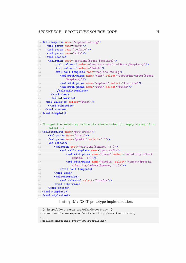
APPENDIX B. PROTOTYPE SOURCE CODE H
128 <xsl:template name="replace-string">129 <xsl:param name="text"/>130 <xsl:param name="replace"/>131 <xsl:param name="with"/>132 <xsl:choose>133 <xsl:when test="contains($text,$replace)">134 <xsl:value-of select="substring-before($text,$replace)"/>135 <xsl:value-of select="$with"/>136 <xsl:call-template name="replace-string">137 <xsl:with-param name="text" select="substring-after($text,
$replace)"/>138 <xsl:with-param name="replace" select="$replace"/>139 <xsl:with-param name="with" select="$with"/>140 </xsl:call-template>141 </xsl:when>142 <xsl:otherwise>143 <xsl:value-of select="$text"/>144 </xsl:otherwise>145 </xsl:choose>146 </xsl:template>147
148
149 <!-- get the substring before the *last* colon (or empty string if nocolon) -->
150 <xsl:template name="get-prefix">151 <xsl:param name="qname"/>152 <xsl:param name="prefix" select="’’"/>153 <xsl:choose>154 <xsl:when test="contains($qname, ’:’)">155 <xsl:call-template name="get-prefix">156 <xsl:with-param name="qname" select="substring-after(
$qname, ’:’)"/>157 <xsl:with-param name="prefix" select="concat($prefix,
substring-before($qname, ’:’))"/>158 </xsl:call-template>159 </xsl:when>160 <xsl:otherwise>161 <xsl:value-of select="$prefix"/>162 </xsl:otherwise>163 </xsl:choose>164 </xsl:template>165 </xsl:stylesheet>
Listing B.1: XSLT prototype implementation.
1 (: http://docs.basex.org/wiki/Repository :)2 import module namespace functx = ’http://www.functx.com’;3
4 declare namespace myNs="www.googlle.at";

APPENDIX B. PROTOTYPE SOURCE CODE I
5 declare namespace uuid = "java:java.util.UUID";6
7 (: get current formatted timestamp :)8 declare function myNs:getTimestamp() as xs:string {9 (: "yyyy-MM-dd’T’HH:mm:ss.SSS’Z’" :)
10 concat(substring(replace(string(current-dateTime()),"\+","0"),1,23),"Z")
11 };12
13 (: parse the text :)14 declare function myNs:getParsedText($text as xs:string) as xs:string {15 replace(replace(replace(replace(functx:trim($text), "\\n", "<br>"),
"\\r\\n", "<br>"), """, "\\""), "\\s+", " ")16 };17
18 (: retrieves id of given element. if no id attr is existing, an uuid isgenerated. :)
19 declare function myNs:getId($elem as element()) as xs:string {20 if(empty($elem/@*[local-name()="id"]))21 then replace(uuid:randomUUID(),"_","-")22 else replace($elem/@*[local-name()="id"],"_","-")23 };24
25 (: retrieves id of given element. if no id attr is existing, an uuid isgenerated. :)
26 declare function myNs:getId($id as xs:string, $elem as element()) as xs:string {
27 if(string-length($id)>2)28 then replace($id,"_","-")29 else30 if(empty($elem/@*[local-name()="id"]))31 then replace(uuid:randomUUID(),"_","-")32 else replace($elem/@*[local-name()="id"],"_","-")33 };34
35 (: parses the element and the first two levels. :)36 declare function myNs:parse($id as xs:string, $notam as element()) as
element()* {37
38 let $res := (<fmol>{39
40 (: id term :)41 if($id = "")42 then myNs:getId($notam)43 else myNs:getId(replace($id,"->",""),$notam),44
45 (: ol class:)46 concat(":",replace(name($notam),":","#"),"["),47

APPENDIX B. PROTOTYPE SOURCE CODE J
48 (: attribute of xml ol object:)49 if($id = "")50 then <objattr>{"detectionTimestamp ->",myNs:getTimestamp
(),","}</objattr> union (51 for $attrobj in $notam/@*52 return <objattr>{replace(name($attrobj),":","#"),"->"",
data($attrobj),"","}</objattr>)53 else for $attrobj in $notam/@*54 return <objattr>{replace(name($attrobj),":","#"),"->"",
data($attrobj),"","}</objattr>55 ,56
57 (: children of the xml element representing associations :)58 for $attr in $notam/*59 return60 <attr>{61
62 (: ol attribute name :)63 replace(name($attr),":","#"),64
65 (: ol attribute can have own attributes, text content or referto other ol objects:)
66 if(count($attr/@*)>0)67 then68 (: output attributes of the xml association element:)69 for $attrattr in $attr/@*70 return <attrattr>{concat("(",name($attrattr),")","->",data(
$attrattr))}</attrattr>71 else72 if(count($attr/*)>0)73 then74 (: lvl 2 - referred ol objects:)75 for $subobj in $attr/*76 return <toParse><subobjid>{concat("->",myNs:getId($subobj
))}</subobjid><subobjname>{$subobj}</subobjname></toParse>
77 else78 (: text value of xml attribute elements:)79 concat("->"",myNs:getParsedText($attr),"""),80
81 ","82 }</attr>,83 "].84
85 "86 }</fmol>)87
88 return if($id = "")89 then $res

APPENDIX B. PROTOTYPE SOURCE CODE K
90 else91 let $subres := (92 for $subobj at $pos in $res//toParse return93 myNs:parse($subobj/subobjid,$subobj/subobjname/*)94 )95 return <a>{$res, $subres}</a>96 };97
98 (: define database existing in BaseX:)99 let $db := ’NOTAM’
100
101 (: query all notams encoded as AIXMBasicMessages :)102 let $notams := (for $y in doc($db)//* where local-name($y) = "
AIXMBasicMessage" return $y)103
104 (: query all namespaces:)105 let $prefixes := (106 for $elem in doc($db)//* return107 for $prefix in fn:in-scope-prefixes($elem)108 return <ns><prefix>{":- prefix ",$prefix,"="}</prefix><uri>{""
;",fn:namespace-uri-for-prefix($prefix,$elem),"".109 "}</uri></ns>110 )111 let $distincPrefixes := fn:distinct-values($prefixes)112
113 (: parse the first level :)114 let $parsedNotams := (115 for $notam in $notams116 return myNs:parse("",$notam)117 )118
119 (: retrieve all f-molecules of the child nodes:)120 let $subFMols := (121 for $subobj at $pos in $parsedNotams//toParse122 return myNs:parse($subobj/subobjid,$subobj/subobjname/*)123 )124
125 (: remove elements which where needed only for the recursion :)126 let $cleanedParserNotams := (functx:remove-elements-deep($parsedNotams
,’subobjname’))127 let $cleanedSubFMol := (functx:remove-elements-deep($subFMols,’
subobjname’))128
129 (: join the sequences to stirngs :)130 let $output0 := string-join($distincPrefixes)131 let $output1 := string-join($cleanedParserNotams)132 let $output2 := string-join($cleanedSubFMol)133 let $output := concat($output0,$output1,$output2)134 let $output := replace($output,",\].","].")

APPENDIX B. PROTOTYPE SOURCE CODE L
135 return $output
Listing B.2: XQuery prototype implementation.
1 public class DOMParser {2
3 private OLProgram olProgram;4
5 public DOMParser() {6 olProgram = new OLProgram("olProgram");7 }8
9 public OLProgram startParser(String file) {10
11 DocumentBuilder builder;12 DocumentBuilderFactory factory = DocumentBuilderFactory.
newInstance();13 factory.setNamespaceAware(true);14 Document doc = null;15
16 try {17 builder = factory.newDocumentBuilder();18
19 // create xml document in memory20 doc = builder.parse(new File(file));21
22 } catch (ParserConfigurationException | SAXException | IOExceptione) {
23 e.printStackTrace();24 }25
26 // select root element. can be query, result, FeatureCollection27 Element root = doc.getDocumentElement();28
29 OLFMolecule parentFMol = null;30
31 parseNode(doc, parentFMol, root, 0, getNodeName(root));32
33 return olProgram;34 }35
36 /**37 * Recursive method which iterates top-down through all elements of
an given node.38 * Creates and adds new f-molecules to the OL program.39 * @param parentFMol40 * @param node41 */

APPENDIX B. PROTOTYPE SOURCE CODE M
42 private void parseNode(Document doc, OLFMolecule parentFMol, Nodenode, int level, String parent) {
43
44 if(node.getNodeType() == Node.ELEMENT_NODE) {45 // only element nodes can be an object- or attribute-element46
47 if(!parent.equals(getNodeName(node.getParentNode()))) {48 level++;49 parent = getNodeName(node.getParentNode());50 }51
52 if(!(level%2==0)) {53 // object-element54
55 OLFMolecule fMol = null;56
57 fMol = initFMolecule(node);58
59 fMol.setAttributes(getNodeAttr(olProgram,node, fMol.getAttributes()));
60
61 // add a detection timestamp to Notams aka AXIMBasicMessage62 String timestamp ="";63 if(node.getLocalName() != null && node.getLocalName().equals("
AIXMBasicMessage") || node.getLocalName() != null && node.getLocalName().equals("Query")) {
64
65 try{66 SimpleDateFormat formatter = new SimpleDateFormat("yyyy-MM-
dd’T’HH:mm:ss.SSS’Z’");67 Date currentTime = new Date();68 timestamp = formatter.format(currentTime);69 }70 catch(Exception e){71 e.printStackTrace();72 }73
74 fMol.addFMolAttr("detectionTimestamp", new OLLiteral("timestamp", timestamp));
75 }76
77 // parse child nodes - start recursion78 if(node.hasChildNodes()) {79 for(int i=0; i<node.getChildNodes().getLength();i++) {80 parseNode(doc, fMol, node.getChildNodes().item(i), level,
parent);81 }82 }83

APPENDIX B. PROTOTYPE SOURCE CODE N
84 olProgram.addMolecule(fMol);85 }86 else if(parentFMol != null && !isEmptyAttrElem(node)) {87 // attribute-element88
89 // add node attributes to f-molecule attributes90 parentFMol.setAttributes(getNodeAttr(olProgram, node, parentFMol
.getAttributes()));91
92 // handle html as text (formattedText), the child elementsincluding html are not correctly parsed (multiple parsed)
93 if(getNodeName(node).equals("formattedText")) {94 addFormattedText(olProgram, parentFMol, node);95 Element parentNode = (Element) node.getParentNode();96 parentNode.removeChild(node);97 }98
99 // second level100 for(int i=0; i<node.getChildNodes().getLength(); i++) {101
102 Node childNode = node.getChildNodes().item(i);103
104 // objects are added as attr -> obj105
106 if(childNode.getNodeType() == Node.ELEMENT_NODE) {107
108 if(!parent.equals(getNodeName(childNode.getParentNode()))) {109 level++;110 parent = getNodeName(childNode.getParentNode());111 }112
113 if(!(level%2 == 0)) {114
115 if(!isIdExisting(childNode)) {116
117 // add ’id’ directly to the node which is then parsedcorrectly
118 String id = ("uuid_".concat(UUID.randomUUID().toString())).replace("-", "_");
119 ((Element)childNode).setAttribute("id", id);120 parentFMol.addFMolAttr((node.getPrefix() == null ? "" :
node.getPrefix().concat(":")).concat(getNodeName(node)), new OLLiteral("id",id));
121 }122 else {123 parentFMol.addFMolAttr((node.getPrefix() == null ? "" :
node.getPrefix().concat(":")).concat(getNodeName(node)), getNodeId(childNode));
124 }

APPENDIX B. PROTOTYPE SOURCE CODE O
125
126 // recursion starts here for new object127 parseNode(doc, null, childNode,level, parent);128 }129 }130 else if(childNode.getNodeType() == Node.TEXT_NODE) {131 // Simple Elements - Text within elements and no children ->
getNodeValues132 String text = getParsedString(childNode.getNodeValue());133
134 if(text.length() > 0) {135 parentFMol.addFMolAttr((node.getPrefix() == null ? "" :
node.getPrefix().concat(":")).concat(getNodeName(node).replace(’:’,’#’)), new OLLiteral(getNodeName(node).replace(’:’,’#’),text));
136 }137 }138 }139 }140 }141 }142
143 ...144 }
Listing B.3: DOM XML prototype implementation.


![Triple Mapper™ Triple Mapper ™ - [겜맥] 게임을 더욱 재미있게- · 2012-12-13 · Triple MapperTriple Mapper™ ™는는키보드에서사용되는키값을다른개체로옮기는키보드에서사용되는키값을다른개체로옮기는](https://img.pdfslide.net/doc/110x75/5d2afecc88c993140a8d0fdb/triple-mapper-triple-mapper-.jpg)