Embed Size (px)
Citation preview

Freescale SemiconductorApplication Note
Document Number: AN4332Rev. 0, 08/2011
Contents
Introduction . . . . . . . . . . . . . . . . . . . . . . . . . . . . . . . . . . . 1IEEE 1588 basic overview. . . . . . . . . . . . . . . . . . . . . . . . 2
2.1 Synchronization principle. . . . . . . . . . . . . . . . . . . . . 32.2 Timestamping . . . . . . . . . . . . . . . . . . . . . . . . . . . . . 5IEEE 1588 implementation for Kinetis K60 based on MQX1588 library . . . . . . . . . . . . . . . . . . . . . . . . . . . . . . . 6
3.1 Hardware components . . . . . . . . . . . . . . . . . . . . . . 63.2 Software components . . . . . . . . . . . . . . . . . . . . . . . 8Detailed description of the IEEE1588 demo software . . 10
4.1 MQX1588 library usage. . . . . . . . . . . . . . . . . . . . . 104.2 MQX tasks list . . . . . . . . . . . . . . . . . . . . . . . . . . . . 114.3 Nonvolatile storage . . . . . . . . . . . . . . . . . . . . . . . . 124.4 Timestamping . . . . . . . . . . . . . . . . . . . . . . . . . . . . 134.5 User interface . . . . . . . . . . . . . . . . . . . . . . . . . . . . 13IEEE1588 demo . . . . . . . . . . . . . . . . . . . . . . . . . . . . . . 21
5.1 Hardware setup and jumper settings. . . . . . . . . . . 215.2 Measuring the clock synchronicity. . . . . . . . . . . . . 24Conclusion. . . . . . . . . . . . . . . . . . . . . . . . . . . . . . . . . . . 26
Implementing an IEEE 1588 V2 Node on the Kinetis K60 Using the Freescale MQX IEEE 1588 Communication Libraryby: Michal Princ
System Application EngineerRoznov Czech System Center
1 IntroductionThis application note describes implementation of the IEEE® 1588 V2 Precision Time Protocol (PTP) on the Kinetis® K60 processor running the MQX™ Operating System. The solution is targeting the TWR-K60N512 KIT and Freescale’s Kinetis K60 microprocessor. The demo software runs under the Freescale MQX Real Time Operation System and uses the Freescale MQX IEEE 1588 Communication Library. The library is based on the IEEE 1588 V2 protocol software by IXXAT Automation GmbH.
12
3
4
5
6
© Freescale Semiconductor, Inc., 2011. All rights reserved.
IEEE 1588 basic overview
This document discusses the following topics:
• IEEE 1588 protocol basics
• IEEE 1588 protocol implementation for Kinetis K60 based on MQX1588 library
• Description of the IEEE 1588 demo application targeting the TWR-K60N512 KIT
2 IEEE 1588 basic overviewThe IEEE 1588 standard is known as Precision Clock Synchronization Protocol for Networked Measurement Control Systems, also known as Precision Time Protocol (PTP). The IEEE 1588 PTP allows clocks distributed across an Ethernet network to be accurately synchronized using a process whereby the distributed nodes exchange timestamped messages.
The technology behind the standard was originally developed by Agilent Technologies® and was used for distributed measuring and control tasks. The challenge is to synchronize networked measuring devices with each other in terms of time, making them able to record measured values and providing them with a precise system timestamp. Based on this timestamp, the measured values can then be correlated with each other.
Typical applications of the IEEE 1588 time synchronization include:
• Time-sensitive telecommunication services that require precise time synchronization between communicating nodes
• Industrial network switches that synchronize sensors and actuators over a single wire distributed control network to control an automated assembly process
• Powerline networks that synchronize across large-scale distributed power grid switches to enable smooth transfer of power
• Test/measurement devices that must maintain accurate time synchronization with the device under test in many different operating environments
• Printing machines, cooperative robotic systems, and residential Ethernet
These applications require precise clock synchronization between devices with accuracy in the sub-microsecond range. It is a remarkable feature of the IEEE 1588 that this synchronization precision is achieved through regular Ethernet connectivity with standard Ethernet frames.
This solution allows nearly any device of any performance to participate in high-precision synchronized networks that are simple to operate and configure.
Other key benefits of the IEEE 1588 protocol include:
• Convergence times of less than a minute for sub-microsecond synchronization between heterogeneous distributed devices with different clocks, resolution, and stability.
• Automatic configuration and segmentation. Each node uses the best master clock algorithm (BMC) to determine the best clock in the segment. Every PTP node stores its features within a specified dataset. These features are transmitted to other nodes within its sync telegrams. Based on this, other nodes are able to synchronize their datasets with the features of the actual master and can adjust their clocks. The cyclic running of the BMC also allows hot swapping; that is, nodes can be connected or removed during propagation time.
Implementing an IEEE 1588 V2 Node on the Kinetis K60, Rev. 0
Freescale Semiconductor2
IEEE 1588 basic overview
• Simple configuration and operation with low compute resource and network bandwidth consumption
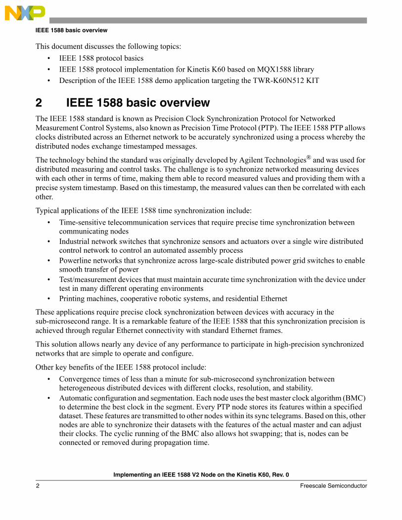
2.1 Synchronization principleNetwork clocks are organized in a master-slave hierarchy. IEEE 1588 identifies the master clock and then establishes two-way timing exchange by which the master sends messages to its slaves to initiate synchronization. Each slave then responds to synchronize itself to its master. This sequence is repeated throughout the specified network to achieve and maintain clock synchronization.
The process starts with one node (master clock) transmitting a sync telegram that contains the estimated transmission time. The exact transmission time of the sync telegram is captured by a clock and transmitted in a second follow-up message. By comparing the timestamp information contained within the first and second telegrams against its own clock, the receiver can calculate the time difference between its own clock and the master clock (see Figure 1). Sync and follow-up messages are sent as multicast. Some IEEE 1588 systems enable hardware timestamping and the insertion of actual timestamps into the sync message. In this case, follow up messages are not needed (so called one-step mode of operation).
Figure 1. Offset and delay measurement—sync message, follow-up message
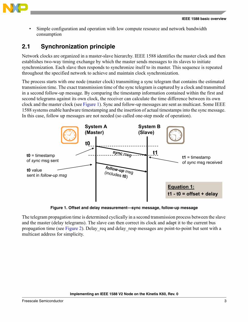
The telegram propagation time is determined cyclically in a second transmission process between the slave and the master (delay telegrams). The slave can then correct its clock and adapt it to the current bus propagation time (see Figure 2). Delay_req and delay_resp messages are point-to-point but sent with a multicast address for simplicity.
Equation 1:
t1 - t0 = offset + delay
t0
sync msg
follow-up msg(includes t0)
t0 = timestampof sync msg sent
t1t1 = timestampof sync msg received
t0 valuesent in follow-up msg
System A (Master)
System B(Slave)
Implementing an IEEE 1588 V2 Node on the Kinetis K60, Rev. 0
Freescale Semiconductor 3
IEEE 1588 basic overview
Figure 2. offset and delay measurement—delay messages
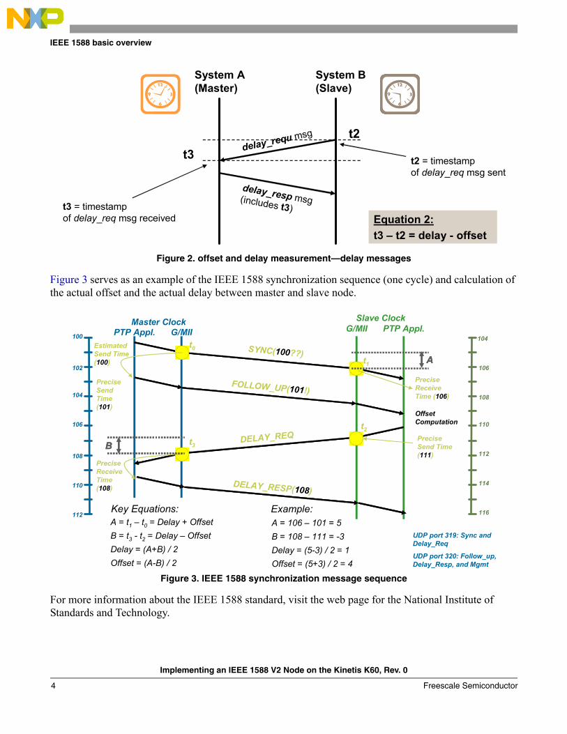
Figure 3 serves as an example of the IEEE 1588 synchronization sequence (one cycle) and calculation of the actual offset and the actual delay between master and slave node.
Figure 3. IEEE 1588 synchronization message sequence
For more information about the IEEE 1588 standard, visit the web page for the National Institute of Standards and Technology.
t3delay_requ msg
delay_resp msg(includes t3)t3 = timestampof delay_req msg received
t2
t2 = timestampof delay_req msg sent
Equation 2:
t3 – t2 = delay - offset
System A (Master)
System B(Slave)
PTP Appl.Master Clock
G/MII G/MIISlave Clock
PTP Appl.
t0
t3
t2
t1
Estimated Send Time (100)
Precise Send Time (101)
Precise Receive Time (106)
SYNC(100??)
FOLLOW_UP(101!)
Precise Send Time (111)
DELAY_REQ
DELAY_RESP(108)
Precise Receive Time (108)
Offset Computation
100
102
110
104
106
108
112
104
106
114
108
110
112
116
AAA
BBB
Key Equations:A = t1 – t0 = Delay + Offset
B = t3 - t2 = Delay – Offset
Delay = (A+B) / 2
Offset = (A-B) / 2
Example:A = 106 – 101 = 5
B = 108 – 111 = -3
Delay = (5-3) / 2 = 1
Offset = (5+3) / 2 = 4
UDP port 319: Sync and Delay_Req
UDP port 320: Follow_up, Delay_Resp, and Mgmt
Implementing an IEEE 1588 V2 Node on the Kinetis K60, Rev. 0
Freescale Semiconductor4
IEEE 1588 basic overview
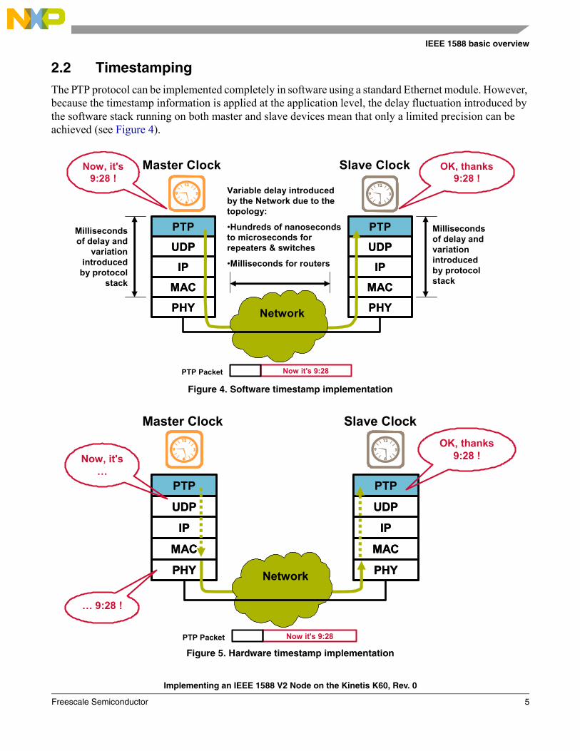
2.2 TimestampingThe PTP protocol can be implemented completely in software using a standard Ethernet module. However, because the timestamp information is applied at the application level, the delay fluctuation introduced by the software stack running on both master and slave devices mean that only a limited precision can be achieved (see Figure 4).
Figure 4. Software timestamp implementation
Figure 5. Hardware timestamp implementation
PTP
UDP
IP
MAC
PHY
PTP
UDP
IP
MAC
PHY
Master Clock
PTP
UDP
IP
MAC
PHY
PTP
UDP
IP
MAC
PHY
Slave Clock
Milliseconds of delay and
variation introduced
by protocol stack
Variable delay introduced by the Network due to the topology:
•Hundreds of nanoseconds to microseconds for repeaters & switches
•Milliseconds for routers
Milliseconds of delay and variation introduced by protocol stack
Now, it's 9:28 !
OK, thanks9:28 !
Now it's 9:28PTP Packet
Network
PTP
UDP
IP
MAC
PHY
PTP
UDP
IP
MAC
PHY
Master Clock
PTP
UDP
IP
MAC
PHY
PTP
UDP
IP
MAC
PHY
Slave Clock
Now, it's …
… 9:28 !
OK, thanks9:28 !
Now it's 9:28PTP Packet
Network
Implementing an IEEE 1588 V2 Node on the Kinetis K60, Rev. 0
Freescale Semiconductor 5
IEEE 1588 implementation for Kinetis K60 based on MQX1588 library
It is possible to minimize the impact of the protocol stack delay by taking timestamps closer to the physical interface, that is, at the MAC or PHY layers (see Figure 5). Dedicated hardware with timestamping capabilities, such as MAC-NET peripheral module of the Freescale Kinetis K60, allows synchronization with significantly improved accuracy.
3 IEEE 1588 implementation for Kinetis K60 based on MQX1588 library
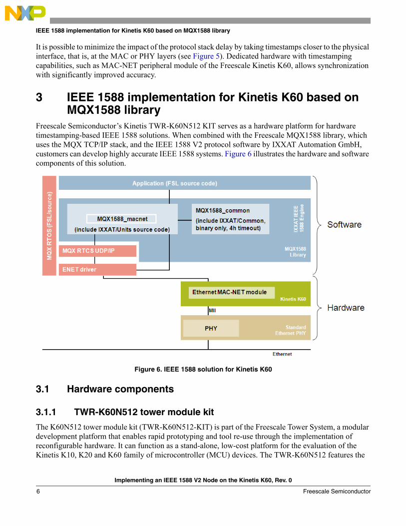
Freescale Semiconductor’s Kinetis TWR-K60N512 KIT serves as a hardware platform for hardware timestamping-based IEEE 1588 solutions. When combined with the Freescale MQX1588 library, which uses the MQX TCP/IP stack, and the IEEE 1588 V2 protocol software by IXXAT Automation GmbH, customers can develop highly accurate IEEE 1588 systems. Figure 6 illustrates the hardware and software components of this solution.
Figure 6. IEEE 1588 solution for Kinetis K60
3.1 Hardware components
3.1.1 TWR-K60N512 tower module kit
The K60N512 tower module kit (TWR-K60N512-KIT) is part of the Freescale Tower System, a modular development platform that enables rapid prototyping and tool re-use through the implementation of reconfigurable hardware. It can function as a stand-alone, low-cost platform for the evaluation of the Kinetis K10, K20 and K60 family of microcontroller (MCU) devices. The TWR-K60N512 features the
Implementing an IEEE 1588 V2 Node on the Kinetis K60, Rev. 0
Freescale Semiconductor6

IEEE 1588 implementation for Kinetis K60 based on MQX1588 library
Kinetis K60 low-power microcontroller based on the ARM® Cortex™-M4 architecture with USB 2.0 full-speed OTG controller and 10/100 Mbps Ethernet MAC.
The TWR-K60N512-KIT includes:
• TWR-K60N512 MCU module
• TWR-SER, a serial module including USB host/device/OTG, Ethernet, CAN, RS232, and RS485
• TWR-ELEV, the primary and secondary elevator modules
The TWR-K60N512 MPU module features include:
• K60N512 in 144 MAPBGA, K60N512VMD100
• Capacitive touch pads
• Integrated, open source JTAG
• SD card slot
• MMA7660 3-axis accelerometer
• Tower Plug-In (TWRPI) socket for expansion (sensors, etc.)
• Tower connectivity for access to USB, Ethernet, RS232/RS485, CAN, SPI, I²C, Flexbus, etc.
• Potentiometer, four LEDs, two pushbuttons, and an infrared port
For more information about the TWR-K60N512-KIT, refer to the TWR-K60N512 Tower Module User's Manual, TWR-K60N512-UM, or visit www.freescale.com/tower.
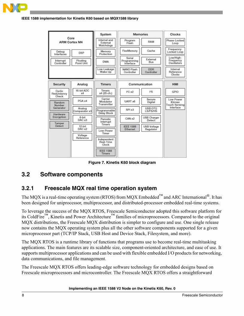
3.1.2 Kinetis K60 32-bit microprocessor
Kinetis is the most scalable portfolio of low power, mixed signal ARM®Cortex™-M4 MCUs in the industry. Phase 1 of the portfolio consists of five MCU families with over 200 pin-, peripheral- and software-compatible devices. Each family offers excellent performance, memory, and feature scalability with common peripherals, memory maps, and packages, providing easy migration both within and between families.
Kinetis MCUs are built from Freescale’s innovative 90nm Thin Film Storage (TFS) flash technology with unique FlexMemory. Kinetis MCU families combine the latest low power innovations and high performance, high precision mixed-signal capability with a broad range of connectivity, human-machine interface, and safety & security peripherals. Kinetis MCUs are supported by a market-leading enablement bundle from Freescale and numerous ARM 3rd party ecosystem partners.
The K60 MCU family includes IEEE 1588 Ethernet, full- and high-speed USB 2.0 On-The-Go with device charge detect capability, hardware encryption and tamper detection capabilities. Devices start from 256 KB of flash in 100LQFP packages extending up to 1 MB in a 256 MAPBGA package with a rich suite of analog, communication, timing, and control peripherals. High memory density K60 family devices include an optional single precision floating point unit, NAND flash controller and DRAM controller.
Figure 7 is a block diagram for the K60 family of microprocessors. For more information, refer to the K60 Sub-Family Reference Manual, K60P104M100SF2RM.
Implementing an IEEE 1588 V2 Node on the Kinetis K60, Rev. 0
Freescale Semiconductor 7
IEEE 1588 implementation for Kinetis K60 based on MQX1588 library
Figure 7. Kinetis K60 block diagram
3.2 Software components
3.2.1 Freescale MQX real time operation system
The MQX is a real-time operating system (RTOS) from MQX Embedded™ and ARC International®. It has been designed for uniprocessor, multiprocessor, and distributed-processor embedded real-time systems.
To leverage the success of the MQX RTOS, Freescale Semiconductor adopted this software platform for its ColdFire™, Kinetis and Power Architecture™ families of microprocessors. Compared to the original MQX distributions, the Freescale MQX distribution is simpler to configure and use. One single release now contains the MQX operating system plus all the other software components supported for a given microprocessor part (TCP/IP Stack, USB Host and Device Stack, Filesystem, and more).
The MQX RTOS is a runtime library of functions that programs use to become real-time multitasking applications. The main features are its scalable size, component-oriented architecture, and ease of use. It supports multiprocessor applications and can be used with flexible embedded I/O products for networking, data communications, and file management.
The Freescale MQX RTOS offers leading-edge software technology for embedded designs based on Freescale microprocessors and microcontroller. The Freescale MQX RTOS offers a straightforward
Implementing an IEEE 1588 V2 Node on the Kinetis K60, Rev. 0
Freescale Semiconductor8

IEEE 1588 implementation for Kinetis K60 based on MQX1588 library
application programming interface (API) with a modular, component-based architecture that makes it simple to fine-tune custom applications. It also allows developers to add web servers, e-mail, network management, security, and routing to their designs. Components are linked in only if needed, preventing unused functions from bloating the memory footprint. By leveraging Freescale’s strong network of partners, Freescale MQX software solutions easily scale across third-party software and tools such as security, industrial protocols, and graphical plug-ins.
For more information, refer to Freescale MQX Real-Time Operating System User’s Guide, MQXUG, or Freescale MQX Real-Time Operating System Reference Manual, MQXRM, or visit www.freescale.com/mqx.
3.2.2 Freescale MQX1588 library
The Freescale MQX1588 library was created to support IEEE1588 V2 standard in the MQX RTOS and to provide users with an easy way to develop IEEE1588 applications in MQX-based systems. The MQX1588 library is based on the IEEE 1588 V2 protocol software by IXXAT Automation GmbH, adapted for usage in the MQX environment.
The IXXAT IEEE 1588 V2 stack is a full implementation of the IEEE 1588-2008 standard with the following features:
• Ordinary/boundary clock
• Transparent clock
• Unicast messaging
• Best master algorithm
• One step/two step support
• Peer-to-peer and end-to-end delay mechanism
• Management protocol/interface
• Simple API for interfacing the application
• Runs with and without OS
• Easily adaptable to target hardware, UDP/IP stack and OS
• Optimized filter algorithms for the usage in standard Ethernet networks with high bus loads
For more information, refer to Freescale MQX IEEE1588 Communication Library User’s Guide, MQX1588UG.
3.2.3 MQX RTCS full-featured TCP/IP stack
Freescale MQX Real-Time TCP/IP Communication Suite (RTCS) is a fast and low-footprint embedded internet stack that supports a rich set of standard protocols that span from data link to application layer such as FTP, Telnet, DHCP, DNS servers and clients, and SNMP clients. It provides great flexibility ranging from simple application such as Ethernet-serial to complex gateway systems. It also allows developers to add Web servers, e-mail, network management, security, and routing to their designs.
For more information, refer to Freescale MQX RTCS User’s Guide, MQXRTCSUG.
Implementing an IEEE 1588 V2 Node on the Kinetis K60, Rev. 0
Freescale Semiconductor 9

Detailed description of the IEEE1588 demo software
4 Detailed description of the IEEE1588 demo softwareA demonstration application has been created to show the functionality and usage of the MQX1588 library. This demo application provides an example of how to:
• Set up all parts of the application including the RTCS
• Use the MQX1588 library
• Implement user-overridable MQX1588API functions
• Realize nonvolatile storage using the standard MQX NAND Flash driver
• Implement the user interface for the application (Shell, Telnet, and HTTP Web Server)
The demo software goes with the installation of the MQX1588 library and can be found in the demo folder of the mqx1588lib software package. The application projects can be found in the following subdirectories:
• cw10: dedicated for CodeWarrior Development Studio for Microcontrollers Version 10 projects
• iar: dedicated for IAR Embedded Workbench for ARM projects
Start by opening the iar\demo1588_two_step_twrk60n512.ewp project file in IAR Embedded Workbench for ARM 6.10 or the cw10\demo1588_two_step_twrk60n512\.project file in the CodeWarrior 10. Both projects contain basic three build targets:
• Int. Flash Release—this target is suitable for final application deployment. When programmed to Flash, the application starts immediately after reset. Variables are allocated in internal SRAM memory.
• Int. Flash Debug—same as above, only the Debug-compiled libraries are used. This target is suitable for debugging before deployment. On boards without external memory, this is the only target suitable for debugging larger applications.
• Int. Ram Release—solely for debugging purposes with code located in the internal RAM memory. Both code and variables are located in this internal memory. Application executable is loaded to RAM automatically by the debugger.
• Int. Ram Debug—same as above, only the Debug-compiled libraries are used. This target is suitable for debugging before deployment.
The application requires Freescale MQX 3.7 to be installed and rebuilt with compile-time configuration options as stated in Chapter 3 of the Freescale MQX IEEE1588 Communication Library User’s Guide.
4.1 MQX1588 library usageThe following binary libraries from the MQX1588 library are used in the demo software. Debug versions of binary images (postfix _d) are used in Debug targets and release version of binary images are used in release targets.
Implementing an IEEE 1588 V2 Node on the Kinetis K60, Rev. 0
Freescale Semiconductor10
Detailed description of the IEEE1588 demo software
The user-overridable API functions for the MQX1588 library are implemented in the MQX1588user.c file. This file implements two functions for reading and writing the MQX1588 configuration data to/from the nonvolatile storage (external NAND flash memory) and one error callback function.
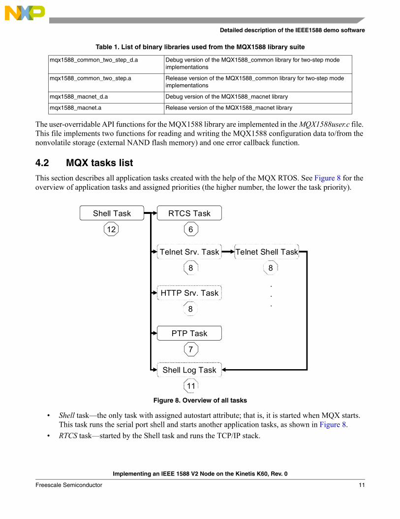
4.2 MQX tasks listThis section describes all application tasks created with the help of the MQX RTOS. See Figure 8 for the overview of application tasks and assigned priorities (the higher number, the lower the task priority).
Figure 8. Overview of all tasks
• Shell task—the only task with assigned autostart attribute; that is, it is started when MQX starts. This task runs the serial port shell and starts another application tasks, as shown in Figure 8.
• RTCS task—started by the Shell task and runs the TCP/IP stack.
Table 1. List of binary libraries used from the MQX1588 library suite
mqx1588_common_two_step_d.a Debug version of the MQX1588_common library for two-step mode implementations
mqx1588_common_two_step.a Release version of the MQX1588_common library for two-step mode implementations
mqx1588_macnet_d.a Debug version of the MQX1588_macnet library
mqx1588_macnet.a Release version of the MQX1588_macnet library
Shell Task
12
RTCS Task
6
Telnet Srv. Task
8
PTP Task
7
Shell Log Task
11
Telnet Shell Task
8
HTTP Srv. Task
8
.
.
.
Implementing an IEEE 1588 V2 Node on the Kinetis K60, Rev. 0
Freescale Semiconductor 11
Detailed description of the IEEE1588 demo software
• Telnet Server task—once enabled (see Section 4.5.2, “Telnet console“), this task listens on a stream socket. Any time a client initiates a connection, the server creates a new Telnet Shell task and redirects the new task’s I/O to the connected socket. Command processing is done by the specified shell.
• HTTP Server task—once enabled (see Section 4.5.2, “Telnet console“), this task handles, evaluates, and responds to HTTP requests.
• PTPMain task—created by the Shell task and runs the PTP engine. As the evaluation version of the IXXAT IEEE 1588 stack is provided, the PTP engine is automatically stopped 4 hours after the MQX start time.
• Telnet Shell task—created by the Telnet Server task and runs the Telnet shell, similar to the shell on the serial port.
• Shell Log task—created either by the Shell task when the serial line shell command “show on” is applied, or by the Telnet Server task when the Telnet shell command “show on” is applied. The Shell Log task prints log data (actual IEEE1588 time, offset to master, master-to-slave delay, slave-to-master delay, one-way delay, drift) once per second, to either the serial console or the Telnet console.
4.3 Nonvolatile storageWith the exception of the MQX1588 configuration data, which relates to the MQX1588 library, the user can specify other application data to be stored in the external NAND flash memory. The following application-specific structure is defined in the MQX1588DEMO.h file:typedef struct { MQX1588_CONFIG lib1588_cfg; boolean autorun; uint_32 checksum;} MQX1588DEMO_CONFIG, _PTR_ MQX1588DEMO_CONFIG_PTR;
lib1588_cfg
This is the configuration structure of the MQX1588 library and its content is vital for proper IEEE 1588 stack functionality. It includes the PTP low-level library-specific parameters, network configuration parameters, and MQX1588 library-specific parameters. See the MQX1588 library documentation for more details about this structure. The MQX1588_ReadConfig() and MQX1588_WriteConfig() user-overridable functions are dedicated for reading out and writing into this structure.
autorun
This enables the automatic resumption of the PTPMain task after its creation and thus starts the clock synchronization process after the board reset without any user intervention.
Implementing an IEEE 1588 V2 Node on the Kinetis K60, Rev. 0
Freescale Semiconductor12

Detailed description of the IEEE1588 demo software
checksum
This 32-bit checksum field is required to maintain and verify MQX1588DEMO_CONFIG structure integrity in the flash memory.
The default_MQX1588DEMOCfg structure of the MQX1588DEMO_CONFIG type is defined in the ptp_cfg.h file. This structure is saved in the external NAND flash memory once the application is started for the first time or once the checksum of the configuration structure saved in the NAND Flash memory is invalid. The user can modify this default configuration structure before project compilation.
Application-specific functions MQX1588DEMO_ReadConfig() and MQX1588DEMO_WriteConfig() that access the MQX1588DEMO_CONFIG structure saved in the NAND flash memory are implemented in the MQX1588DEMO.c file. These functions are used by the MQX1588 library API functions MQX1588_ReadConfig() and MQX1588_WriteConfig() each time the MQX1588 configuration data reading or writing is requested.
4.4 TimestampingThe timestamping capability of the Kinetis K60 10/100Mbps Ethernet MAC-NET module allows the precise timestamping of incoming and outgoing frames. This module incorporates an adjustable timer module which implements a free running 32-bit counter. Through dedicated correction logic, the timer can be adjusted to allow synchronization to a remote master and provide a synchronized timing reference for the local system. The timer can be configured to cause an interrupt after a fixed time period to allow the synchronization of software timers or to perform other synchronized system functions.
When a PTP frame is received, the MAC latches the value of the timer when the frame’s Start Frame Delimiter (SFD) field is detected and provides the captured timestamp on the Rx buffer descriptor. This is done for all received frames.
When transmitting, the client driver (MAC-NET driver) should detect 1588 event frames and indicate in the Tx buffer descriptor that the frame has to be timestamped. Afterwards, the MAC module records the timestamp for the frame in the dedicated register and generates an interrupt to indicate that the new Tx timestamp is available.
Detailed description of the timestamping capabilities of the MAC-NET peripheral module can be found in the K60 Sub-Family Reference Manual, K60P104M100SF2RM.
4.5 User interfaceThe Freescale MQX1588 library-based IEEE 1588 demo application for Kinetis K60 can be interfaced by:
• Serial line console
• Telnet console
• HTTP web server
• IXXAT PTPManager
The following compile-time configuration options must be set in the MQX1588DEMO.h in order to enable the Telnet server and HTTP web server in the application.
Implementing an IEEE 1588 V2 Node on the Kinetis K60, Rev. 0
Freescale Semiconductor 13
Detailed description of the IEEE1588 demo software
4.5.1 Serial line console
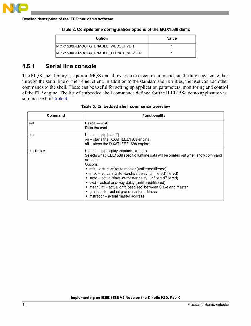
The MQX shell library is a part of MQX and allows you to execute commands on the target system either through the serial line or the Telnet client. In addition to the standard shell utilities, the user can add other commands to the shell. These can be useful for setting up application parameters, monitoring and control of the PTP engine. The list of embedded shell commands defined for the IEEE1588 demo application is summarized in Table 3.
Table 2. Compile time configuration options of the MQX1588 demo
Option Value
MQX1588DEMOCFG_ENABLE_WEBSERVER 1
MQX1588DEMOCFG_ENABLE_TELNET_SERVER 1
Table 3. Embedded shell commands overview
Command Functionality
exit Usage — exitExits the shell.
ptp Usage — ptp [on|off]on – starts the IXXAT IEEE1588 engineoff – stops the IXXAT IEEE1588 engine
ptpdisplay Usage — ptpdisplay <option> <on|off>Selects what IEEE1588 specific runtime data will be printed out when show command executed.Options: • offs – actual offset to master (unfiltered/filtered) • mtsd – actual master-to-slave delay (unfiltered/filtered) • stmd – actual slave-to-master delay (unfiltered/filtered) • owd – actual one-way delay (unfiltered/filtered) • meanDrft – actual drift [psec/sec] between Slave and Master • gmstraddr – actual grand master address • mstraddr – actual master address
Implementing an IEEE 1588 V2 Node on the Kinetis K60, Rev. 0
Freescale Semiconductor14
Detailed description of the IEEE1588 demo software
To set up the serial line shell, which serves as a default user interface, connect your PC and the UART socket of the TWR-SER2 serial board with the RS232 cable. The following parameters of the serial port must be set in order to establish the connection:
• Baud rate: 115200
• Data bits: 8
• Parity: none
• Stop bit: 1
• Flow control: none
The Shell task is started automatically after the reset. Figure 9 shows the welcome message of the shell and the command prompt that displays after reset.
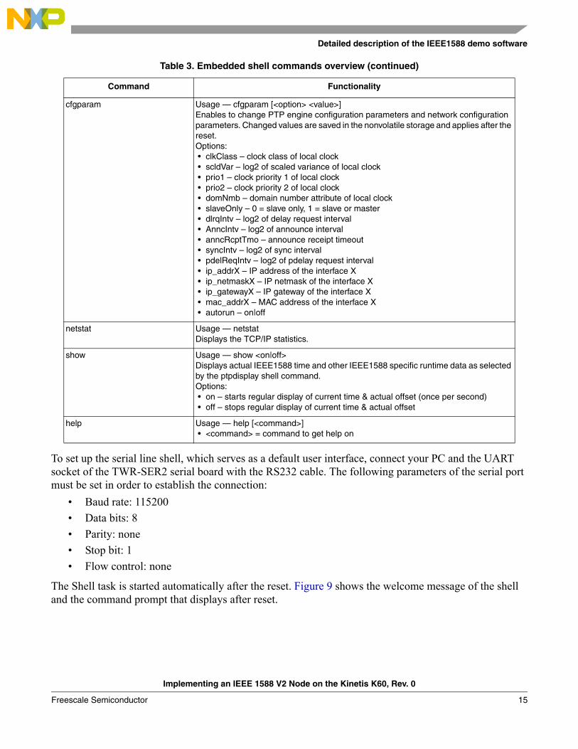
cfgparam Usage — cfgparam [<option> <value>]Enables to change PTP engine configuration parameters and network configuration parameters. Changed values are saved in the nonvolatile storage and applies after the reset.Options: • clkClass – clock class of local clock • scldVar – log2 of scaled variance of local clock • prio1 – clock priority 1 of local clock • prio2 – clock priority 2 of local clock • domNmb – domain number attribute of local clock • slaveOnly – 0 = slave only, 1 = slave or master • dlrqIntv – log2 of delay request interval • AnncIntv – log2 of announce interval • anncRcptTmo – announce receipt timeout • syncIntv – log2 of sync interval • pdelReqIntv – log2 of pdelay request interval • ip_addrX – IP address of the interface X • ip_netmaskX – IP netmask of the interface X • ip_gatewayX – IP gateway of the interface X • mac_addrX – MAC address of the interface X • autorun – on|off
netstat Usage — netstatDisplays the TCP/IP statistics.
show Usage — show <on|off>Displays actual IEEE1588 time and other IEEE1588 specific runtime data as selected by the ptpdisplay shell command.Options: • on – starts regular display of current time & actual offset (once per second) • off – stops regular display of current time & actual offset
help Usage — help [<command>] • <command> = command to get help on
Table 3. Embedded shell commands overview (continued)
Command Functionality
Implementing an IEEE 1588 V2 Node on the Kinetis K60, Rev. 0
Freescale Semiconductor 15

Detailed description of the IEEE1588 demo software
Figure 9. Serial line shell
4.5.2 Telnet console
The MQX1588DEMOCFG_ENABLE_TELNET_SERVER compile-time configuration options must be set in the MQX1588DEMO.h in order to enable the Telnet server in the application (see Table 2).
While using the Telnet console, the embedded command shell is accessible after the communication with the TWR-K60N512-KIT is established. This is done by entering the command open <defined IP address> into the user preferred Telnet Client. A set of Telnet shell commands is the same as for the serial line shell, see Table 3.
Figure 10. Telnet console
4.5.3 HTTP web server
The Hypertext Transfer Protocol (HTTP) server is one of the MQX RTCS components. It is comprised of a simple web server that handles, evaluates, and responds to HTTP requests and can be used as a GUI for the IEEE1588 demo application. Once enabled by the compile time configuration option (see Table 2), it allows the implementation of a web server with support for dynamically generated web pages. Common Gateway Interface (CGI) callback functions are registered with the HTTP server by the application. These
Implementing an IEEE 1588 V2 Node on the Kinetis K60, Rev. 0
Freescale Semiconductor16

Detailed description of the IEEE1588 demo software
functions are called back from the HTTP server when the client requests that the assigned CGI file be retrieved (for example http://169.254.3.3/data1588.cgi).
The content of all application web pages is stored in the flash memory and can be accessible from any web browser by applying the target Ethernet port IP address. The default IP addresses of the board are169.254.3.3. for port0 and 169.254.3.4. for port1.
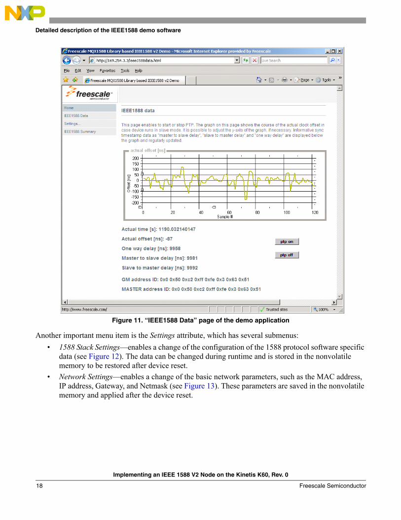
After navigating to the device IP address, the browser window displays a web server welcome page with a user menu on the left side. You can click on the IEEE1588 Data menu item to see the course of the actual clock offset, as in Figure 11. The following selected PTP stack variables are displayed on this page:
• Actual time (s)
• Actual offset (ns)
• One-way delay (ns)
• Master-to-slave delay (ns)
• Slave-to-master delay (ns)
• GrandMaster address
• Master address
This page also allows the start or stop of the PTP engine by clicking on the respective button.
NOTEThe pages contain binary ActiveX graph component to visualize time differences. You may need to add the device IP address to your list of trusted sites to enable automatic installation of this component.
Implementing an IEEE 1588 V2 Node on the Kinetis K60, Rev. 0
Freescale Semiconductor 17
Detailed description of the IEEE1588 demo software
Figure 11. “IEEE1588 Data” page of the demo application
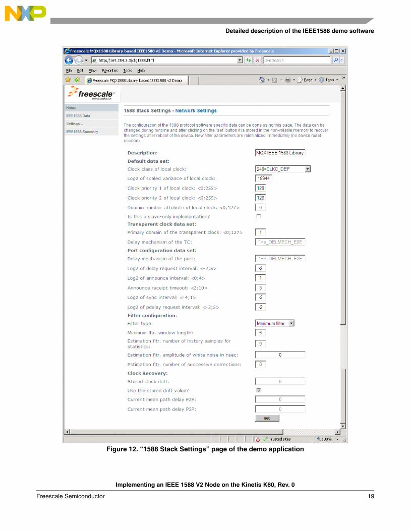
Another important menu item is the Settings attribute, which has several submenus:
• 1588 Stack Settings—enables a change of the configuration of the 1588 protocol software specific data (see Figure 12). The data can be changed during runtime and is stored in the nonvolatile memory to be restored after device reset.
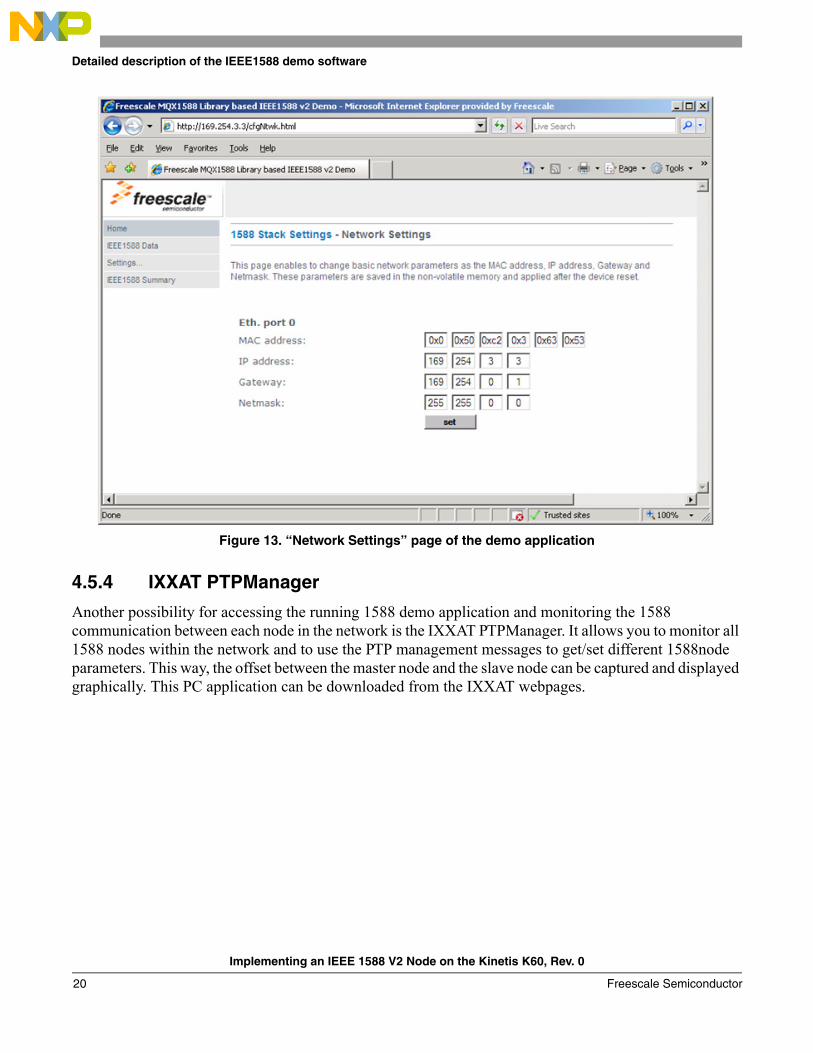
• Network Settings—enables a change of the basic network parameters, such as the MAC address, IP address, Gateway, and Netmask (see Figure 13). These parameters are saved in the nonvolatile memory and applied after the device reset.
Implementing an IEEE 1588 V2 Node on the Kinetis K60, Rev. 0
Freescale Semiconductor18
Detailed description of the IEEE1588 demo software
Figure 12. “1588 Stack Settings” page of the demo application
Implementing an IEEE 1588 V2 Node on the Kinetis K60, Rev. 0
Freescale Semiconductor 19
Detailed description of the IEEE1588 demo software
Figure 13. “Network Settings” page of the demo application
4.5.4 IXXAT PTPManager
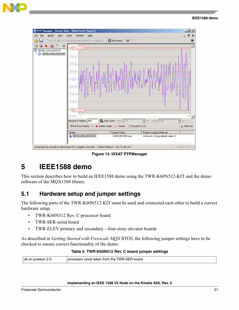
Another possibility for accessing the running 1588 demo application and monitoring the 1588 communication between each node in the network is the IXXAT PTPManager. It allows you to monitor all 1588 nodes within the network and to use the PTP management messages to get/set different 1588node parameters. This way, the offset between the master node and the slave node can be captured and displayed graphically. This PC application can be downloaded from the IXXAT webpages.
Implementing an IEEE 1588 V2 Node on the Kinetis K60, Rev. 0
Freescale Semiconductor20
IEEE1588 demo
Figure 14. IXXAT PTPManager
5 IEEE1588 demoThis section describes how to build an IEEE1588 demo using the TWR-K60N512-KIT and the demo software of the MQX1588 library.
5.1 Hardware setup and jumper settingsThe following parts of the TWR-K60N512-KIT must be used and connected each other to build a correct hardware setup.
• TWR-K60N512 Rev. C processor board
• TWR-SER serial board
• TWR-ELEV primary and secondary—four-story elevator boards
As described in Getting Started with Freescale MQX RTOS, the following jumper settings have to be checked to ensure correct functionality of the demo:
Table 4. TWR-K60N512 Rev. C board jumper settings
J6 on position 2-3 processor clock taken from the TWR-SER board
Implementing an IEEE 1588 V2 Node on the Kinetis K60, Rev. 0
Freescale Semiconductor 21

IEEE1588 demo
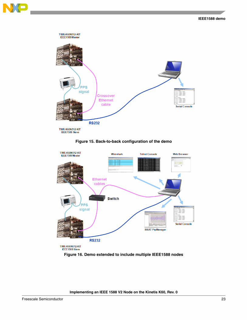
The demo can be configured in a back-to-back (point-to-point) configuration where two boards are connected directly using the crossover Ethernet cable. It deals with a simple type of connection often used for evaluating the system accuracy and the overall performance. The back-to-back configuration using two TWR-K60N512-KITs is illustrated in Figure 15. The application can be interfaced by the serial console only.
Figure 16 shows another demo concept which consists of two or more TWR-K60N512-KITs. An Ethernet switch/hub provides the connection between all boards. The slave node can be interfaced by the serial console or by the Telnet console or by the Internet Explorer web browser or by the IXXAT PTPManager. The user can also monitor the 1588 communication between these 1588 nodes using any network protocol analyzer (WireShark).
Another Freescale evaluation boards with the IEEE1588 support can be involved in the demo to enlarge the IEEE1588 network. The following ColdFire and PowerQUICC boards can be incorporated:
• ColdFire M5234BCC
• ColdFire M52259EVB
• ColdFire TWR-MCF54418 KIT
• PowerQUICC MPC8360MDS
• PowerQUICC MPC8313E-RDB
• i.MX28 Evaluation Kit
Visit www.freescale.com. for updated information about Freescale platforms with the IEEE1588 support.
Table 5. TWR-SER board jumper setting
CLK_SEL 3-4
CLKIN-SEL 2-3 processor clock is taken from PHY
ETH-CONFIG J12 9-10 select RMII communication mode
Implementing an IEEE 1588 V2 Node on the Kinetis K60, Rev. 0
Freescale Semiconductor22
IEEE1588 demo
Figure 15. Back-to-back configuration of the demo
Figure 16. Demo extended to include multiple IEEE1588 nodes
Implementing an IEEE 1588 V2 Node on the Kinetis K60, Rev. 0
Freescale Semiconductor 23

IEEE1588 demo
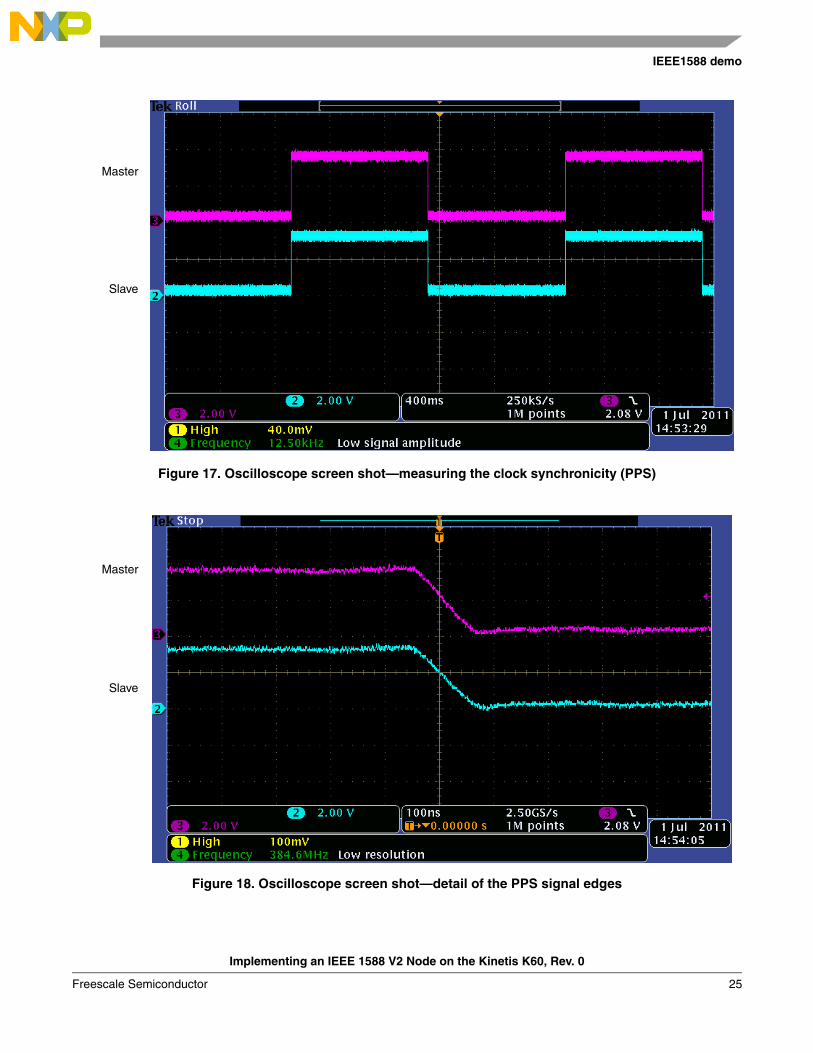
5.2 Measuring the clock synchronicityTo measure the synchronicity of the clocks, the K60 provides an option to generate a pulse-per-second (PPS) signal. This signal is generated directly from the 1588 timer (ENET0_TMR2 by default) and is routed to the GPIO PTC18. This GPIO pin is routed to the J9-21 pin on the primary TWR-ELEV board of the tower system.
To measure and compare PPS signals from different boards, attach the oscilloscope probe to the J9-21 pin of the primary TWR-ELEV board. Figure 17 illustrates clock synchronicity measurement using the oscilloscope.
To measure the clock synchronization accuracy, a test was performed between two TWR-K60N512-KITs connected back-to-back. Table 6 summarizes the configuration of the IXXAT 1588 V2 stack used for testing:
The results of the clock synchronization accuracy test are provided below, see Table 7.
Table 6. 1588 stack configuration for clock synchronization accuracy Testing
1588 configuration Assigned value
Clock basic type Ordinary Clock
Delay request mechanism End-to-End
One-step mode False
Announce message interval 2 seconds
Sync message interval 0.25 seconds
Delay request interval 0.25 seconds
Used filter Minimum filter
Filter window length 6
Measurement period 0.5 hours
Table 7. Clock synchronization accuracy test results
Average clock offset –0.44 ns
Standard deviation 16.16 ns
Peak-to-peak range –51 ns to +57 ns
Implementing an IEEE 1588 V2 Node on the Kinetis K60, Rev. 0
Freescale Semiconductor24
IEEE1588 demo
Figure 17. Oscilloscope screen shot—measuring the clock synchronicity (PPS)
Figure 18. Oscilloscope screen shot—detail of the PPS signal edges
Master
Slave
Master
Slave
Implementing an IEEE 1588 V2 Node on the Kinetis K60, Rev. 0
Freescale Semiconductor 25
Conclusion
6 ConclusionThis application note describes an IEEE 1588 Precision Time Protocol demo application that targets the Kinetis K60 processor and the TWR- K60N512-KIT. The application software runs under the Freescale MQX RTOS and uses the MQX RTCS TCP/IP stack and the Freescale MQX1588 Library for quick IEEE1588 application development. This solution can be easily ported to other processors from the Kinetis family with the MQX and RTCS support.
The demo system can be targeted to applications that require precise clock synchronization between devices with accuracy in the sub-microsecond range. Typical applications include industrial network switches, time-sensitive telecommunication services, powerline networks, and test/measurement devices. For more information and updates go to www.freescale.com.
Implementing an IEEE 1588 V2 Node on the Kinetis K60, Rev. 0
Freescale Semiconductor26

THIS PAGE IS INTENTIONALLY BLANK
Implementing an IEEE 1588 V2 Node on the Kinetis K60, Rev. 0
Freescale Semiconductor 27

Document Number: AN4332Rev. 008/2011
How to Reach Us:
Home Page:www.freescale.com
Web Support:http://www.freescale.com/support
USA/Europe or Locations Not Listed:Freescale Semiconductor, Inc.Technical Information Center, EL5162100 East Elliot RoadTempe, Arizona 85284+1-800-521-6274 or +1-480-768-2130www.freescale.com/support
Europe, Middle East, and Africa:Freescale Halbleiter Deutschland GmbHTechnical Information CenterSchatzbogen 781829 Muenchen, Germany+44 1296 380 456 (English)+46 8 52200080 (English)+49 89 92103 559 (German)+33 1 69 35 48 48 (French)www.freescale.com/support
Japan:Freescale Semiconductor Japan Ltd.HeadquartersARCO Tower 15F1-8-1, Shimo-Meguro, Meguro-ku,Tokyo 153-0064Japan0120 191014 or +81 3 5437 [email protected]
Asia/Pacific:Freescale Semiconductor China Ltd.Exchange Building 23FNo. 118 Jianguo RoadChaoyang DistrictBeijing 100022 China +86 10 5879 [email protected]
For Literature Requests Only:Freescale Semiconductor Literature Distribution Center1-800-441-2447 or 303-675-2140Fax: [email protected]
Information in this document is provided solely to enable system and software implementers to use Freescale Semiconductor products. There are no express or implied copyright licenses granted hereunder to design or fabricate any integrated circuits or integrated circuits based on the information in this document.
Freescale Semiconductor reserves the right to make changes without further notice to any products herein. Freescale Semiconductor makes no warranty, representation or guarantee regarding the suitability of its products for any particular purpose, nor does Freescale Semiconductor assume any liability arising out of the application or use of any product or circuit, and specifically disclaims any and all liability, including without limitation consequential or incidental damages. “Typical” parameters that may be provided in Freescale Semiconductor data sheets and/or specifications can and do vary in different applications and actual performance may vary over time. All operating parameters, including “Typicals”, must be validated for each customer application by customer’s technical experts. Freescale Semiconductor does not convey any license under its patent rights nor the rights of others. Freescale Semiconductor products are not designed, intended, or authorized for use as components in systems intended for surgical implant into the body, or other applications intended to support or sustain life, or for any other application in which the failure of the Freescale Semiconductor product could create a situation where personal injury or death may occur. Should Buyer purchase or use Freescale Semiconductor products for any such unintended or unauthorized application, Buyer shall indemnify and hold Freescale Semiconductor and its officers, employees, subsidiaries, affiliates, and distributors harmless against all claims, costs, damages, and expenses, and reasonable attorney fees arising out of, directly or indirectly, any claim of personal injury or death associated with such unintended or unauthorized use, even if such claim alleges that Freescale Semiconductor was negligent regarding the design or manufacture of the part.
For information on Freescale’s Environmental Products program, go to http://www.freescale.com/epp.
Freescale™ and the Freescale logo are trademarks of Freescale Semiconductor, Inc. All other product or service names are the property of their respective owners.The Power Architecture and Power.org word marks and the Power and Power.org logos and related marks are trademarks and service marks licensed by Power.org
© Freescale Semiconductor, Inc. 2011. All rights reserved.