Embed Size (px)
Citation preview

University of Arkansas, FayettevilleScholarWorks@UARKBiological and Agricultural EngineeringUndergraduate Honors Theses Biological and Agricultural Engineering
5-2018
In-Cage Surface Wetting System for CoolingPoultry in TransportRyan Clark
Follow this and additional works at: http://scholarworks.uark.edu/baeguht
Part of the Biological Engineering Commons, and the Bioresource and Agricultural EngineeringCommons
This Thesis is brought to you for free and open access by the Biological and Agricultural Engineering at ScholarWorks@UARK. It has been accepted forinclusion in Biological and Agricultural Engineering Undergraduate Honors Theses by an authorized administrator of ScholarWorks@UARK. Formore information, please contact [email protected], [email protected].
Recommended CitationClark, Ryan, "In-Cage Surface Wetting System for Cooling Poultry in Transport" (2018). Biological and Agricultural EngineeringUndergraduate Honors Theses. 53.http://scholarworks.uark.edu/baeguht/53
IN-CAGE SURFACE WETTING SYSTEM FOR COOLING POULTRY IN TRANSPORT
Ryan J. Clark
Biological Engineering Program
Biological and Agricultural Engineering Department
College of Engineering
University of Arkansas
Undergraduate Honors Thesis


3
Abstract
Poultry health and mortality rates are important considerations in poultry production, as companies can
minimize product loss and appeal to a consumer base whose concern for animal welfare continues to
grow. Although animal welfare is a consideration for the entire poultry production process, this project
focuses on the live-haul phase of the process, specifically during transport from grow houses to processing
facilities. During the summer months, broiler chickens being transported can suffer from heat stress that
can lead to death. This project consists of the designing and testing of an in-cage surface wetting system
to minimize heat stress incidents in broiler chickens being transported when temperatures exceed 17˚C.
The system that was designed uses a piping system made of PVC and irrigation tubing that allows water
to be sprayed through all areas of the cage using nozzles. The system must deliver 20 mL of water per
bird, requiring a total of 2 L of water per cage when the cage is loaded with 100 broiler chickens. Nozzles
were placed inside each level of the cage in an offset configuration that allows for maximum coverage
within the cage. During testing of the prototype an average of 17.4 mL of water per bird was delivered.
Coverage within the cage was observed to be over 75% during a single spray cycle of 15 seconds. These
results make the designed system an acceptable solution to this problem. Nozzle recommendations for
this type of system include using at least 8 nozzles per level in the cage. A conical spray pattern was
observed to be beneficial as it covered more area in the cage when operating at an appropriate pressure.
The nozzles were able to reach the center of the cage, which is expected to be one of the areas that would
accumulate the most heat during transportation. The system was scaled-up for commercial use taking
insights from the prototype that was tested to optimize the coverage and durability of the system. This
system is expected to reduce the microbial load during transport when the water is treated with a biocide
prior to spraying.

4
Introduction
Animal welfare has become a primary concern in poultry production due to continued pressure
from consumers and animal rights groups. However, poultry health and mortality rates are important
considerations in poultry production, as companies can minimize product loss and use these
considerations in the marketing of their products. Although animal welfare is a consideration for the entire
poultry production process, this project focuses on the live-haul phase of the process, specifically during
transport from grow houses to processing facilities.
The transportation of broiler chickens from grow houses to processing facilities is done in open
cages, on flat-bed trailers. This is one of the few segments of the poultry production system in which
broiler chickens are not in a climate-controlled environment. This means that depending on the season,
these animals can be exposed to extreme temperatures, which in the summer months means elevated
temperatures that cause heat stress. During winter months side boards are added to the transport cages
to minimize heat loss so there is no significant increase in mortality rates (Ritz et al, 2005). The only way
to quantify how many animals experience heat stress during transportation is through dead on arrival
(DOA) numbers, which is a common industry metric. However, this metric accounts for broiler chickens
with causes of death unrelated to heat stress, so the real effect of elevated temperatures on broilers
during transportation is still being studied.
High DOA numbers are a concern in poultry production and companies are beginning to look at
ways of minimizing animal losses to improve company reputations and profitability. Animal loss is
expected throughout the live-haul process and currently reaches 0.35 to 0.37% annually (Agri Stats, Inc.
2003). However, most companies have a goal to reduce these percentages to 0.20% or less (Ritz et al,
2005). This shift in industry expectations means there is a newfound need for systems that reduce
mortality rates of broiler chickens during the live-haul process and improve animal welfare.

5
The goal of this design project is to create an in-cage cooling system to be used in the
transportation of broiler chickens that reduces heat stress and deaths associated with it. Considering
broiler production estimates of 8.49 billion birds per year (USDA, 2003), this system could save
approximately 6.38 billion dollars in the poultry industry (considering a 0.2% mortality rate reduction and
a carcass value of $0.75/lb with average bird weights of 5 lb). Other expected benefits include a reduction
in shrinkage that occurs from broiler chicken’s thermoregulation during transportation and a reduction in
microbial loads if the water is treated with a biocide before spraying.
Public Health and Safety
The system being designed will be transported using public roadways. Therefore, the public will
be exposed to it, and design constraints must include:
• The system must not operate at elevated pressures that would cause it to be classified as a
pressure vessel.
• The system should not create additional hazards in case of an accident during the transportation
process.
• The system cannot create hazardous conditions when operating normally on the roadway for
other drivers, including increasing exposure of the public to poultry fecal matter.
• The system must also be safe for the operators and truck drivers who will be exposed to it
regularly.
The system designed will only spray water, which has no additional regulations, and will operate at lower
pressure ranges, reducing the risk of injury to broiler chickens and the general public.

6
Literature Review
The live-haul process in poultry production encompasses catching, transporting, holding, and
unloading broiler chickens. The purpose is to move broiler chickens from grow houses to processing
facilities. The predominant cause for broilers that are DOA is physical injury incurred during catching and
loading in the pre-transport phase. The second largest cause of death is stress related, affecting broilers
throughout the entire live-haul process (Ritz et al, 2005). This study was not able to identify at which point
of the live-haul process most of the broilers were dying due to the inability to accurate evaluate time of
death. However, this study was able to draw a correlation between heat-stress incurred during the catch,
transport, and holding phases and increased DOA numbers.
European researchers have also found increased incidents of heat-stress in broilers during the
summer months, correlating increased temperatures to increases in DOA numbers. The two main factors
affecting DOA numbers are transport times exceeding two hours and temperatures exceeding 17˚C
(Warris et al, 1992). In this case mortality rates increased by 30% when temperatures reached 17˚C and
continued to increase as temperatures increased (Warris et al, 2005). During their study that spanned
three years, these researchers had DOA rates that peaked at 0.45% in the summer months and were stable
at 0.1% for the rest of the year. This can be compared to a similar study done in Italy, which had DOA rates
of 0.47% in the summer months (Petracci et al, 2006). Warris’ study concluded that up to a temperature
of 17˚C, temperature has little effect on mortality rates during poultry transportation. However, once
temperatures exceed 17˚C, mortality rates steadily increase as the chicken’s ability to thermoregulate
decreases drastically.
Once poultry production started to centralize to large scale operations with high density, the need
for cooling systems arose. In grow houses this is achieved with cooling pads, large fans, and surface
wetting. The most effective of these methods is intermittent surface wetting, as it increases the chicken’s

7
ability to thermoregulate through evaporative cooling. The optimal amount of wetting for broilers is 22
mL per bird when using surface wetting as a means of cooling when temperatures exceed 18˚C (Tao et al,
2002). While this study pertains to grow houses, this recommended value may be applicable to other
areas of poultry production.
Researchers in Antalya, Turkey further quantified the effect of surface wetting on chickens. These
researchers found a difference in core body temperature of up to 2.51˚C when using surface wetting, and
even larger differences in surface temperatures of the hens studied (Mutaf et al, 2008). It is important to
note that in this experiment only 10 mL of water per bird was applied.
A study done at the University of Arkansas compared surface wetting cooling systems and
evaporative cooling systems in a conventional broiler house. The evaporative cooling system used cooling
pads and air flow through the broiler houses to bring temperatures down, whereas the surface wetting
system used sprinklers to apply large water droplets to the broiler chickens at certain intervals. This study
found no significant differences in the cooling ability of either system, however it did find that the surface
wetting system used significantly less water than the evaporative cooling system (Liang et al, 2013).
Design Objectives
The following objectives have been identified for the in-cage cooling system to be used during
poultry transport:
• Easily maintained.
• Easily connected once loaded cages are stacked on truck.
• Cools all levels and areas of the cage.
• System is durable.
• Provides consistent cooling in the cage for the transit duration.

8
• System is safe for chickens and operators.
• Efficiently uses available water.
• Reduces heat-stress incidents in poultry transport.
Design Constraints
The following constraints have been identified for the in-cage cooling system to be used during
poultry transport:
• Does not harm the chickens.
• Does not interfere with regular live-haul operations.
• Does not significantly increase loading and unloading times.
Methods
1. Generate Alternatives
Three possible systems have been identified to help alleviate heat stress in chickens. These systems
are described below.
Pad Evaporative Cooling System
This system is based on current evaporative cooling pad systems used in grow houses. This system
requires moist pads and air flow to achieve an evaporative cooling effect. On a broiler transport truck
these pads could be directly attached to the individual cages, specifically on either side of the cages. This
would allow air to be pushed through the pads when the truck is moving, creating a cool environment for
the broilers. This system would require the pads to be moistened before the truck leaves the grow house.
Because of this system’s simplicity, it is cost effective and durable. However, it provides very little in the
form of controls that would ensure the broilers are consistently kept cool. It’s also ineffective when the

9
truck is not moving, such as in the loading and unloading process, so it would need to be supplemented
with fans in these stages.
Surface Wetting: Drip System
This surface wetting system operates with less water and water delivery can be controlled by
manipulating the pump. It consists of a PVC piping system on the side of each cage that branches off to
each level. Inside each level a soaker hose is attached to the PVC pipe and routed along the roof to provide
maximum coverage. Once the pump is turned on water is forced through the permeable membrane of
the soaker hose, allowing it to drip down onto the broilers. Although this system is efficient, it is difficult
to determine exactly where the dripping will occur. This means that slight variations in the angle of the
cage could cause certain areas to receive more water than others. There are also concerns with the
durability of this system, as the soaker hose would be exposed to the broiler chickens, which could easily
damage it causing the entire system to malfunction.
Surface Wetting: Spray System
This surface wetting system is based off of similar systems currently used in grow houses. It consists
of a PVC piping system that runs up the side of the cage and into each level. Low pressure nozzles placed
at intervals in the piping on each level provide water to the broilers for cooling via surface wetting.
Although the principle behind this system is the same as the one used in grow houses, this system faces
additional challenges when implemented in transport cages. The main challenge that needs to be
overcome in this design is the height difference between the roof and floor of each level of the cage. While
in grow houses the nozzles delivering the water can be suspended high enough to provide wide spray
patterns; in the cage there is only a 25.4 cm clearance. This means careful nozzle selection is required to
provide maximum coverage in the cage, most likely using a flat spray nozzle. Control for this system is also
provided by the pump, and the amount of water delivered can be controlled through intermittent

10
spraying. Durability for this system is expected to be good since it uses PVC piping through most of its
construction.
Both of the surface wetting systems will require modifications to the flat-bed trailers that are used for
transportation of broiler chickens. Water storage and power to run the pump will be needed, however
the design for these falls outside the scope of this project.
2. Evaluate Alternatives
To select the system that meets the objectives for this project, a weighted objectives table is used. In
this table each system receives a ranking from 0 to 5 for its ability to meet each of the stated objectives.
The higher numbers indicate the degree to which the system meets each objective. Each ranking is
multiplied by a weighting factor to provide a score in accordance to each objectives importance. The sum
of these allows the best system to be selected based on the system’s ability to meet all the objectives.
See Table 1 for the weighted objectives table.
Table 1: Weighted Objectives Table.
Objective Weighting Factor Pad System Drip System Spray System
Maintenance 0.05 2 1 4
Ease of Connection on Truck 0.05 5 3 3
Coverage in Cage 0.2 2 3 5
Durability 0.15 2 1 3
Consistency 0.15 1 3 5
Safety 0.35 5 4 4
Efficient Water Use 0.05 2 3 5
Sum 1 3.05 2.95 4.2
From the weighted objectives table, it is determined that the surface wetting system using the spray
nozzles is the system that consistently will meet the stated objectives. This is the system selected to be
designed.

11
3. System Design
A surface wetting system using spray nozzles to deliver water into the poultry transport cages will
require a modular system. Since cages are loaded and unloaded randomly, the system must feature a
universal connection from the module mounted on the cage, to the system that will hold and deliver water
mounted on the flat-bed trailer. The modules mounted on the cage will need to be durable to handle the
loading and unloading process and remain out of the way of the forklift operator for this system to be
feasible. The water reservoir and central pumping system will need to be mounted on the flat-bed trailer
and must not interfere with it’s handling while on public roadways.
It is proposed that the cage-mounted modules use two lines in each level of the cage with nozzles
installed on each line to deliver water towards the middle of the cage. The lines will be mounted to the
support beams along the roof of each level, one on the door side and one on the back side. Each line into
the cage will have four nozzles installed horizontally towards the middle of the cage. The nozzles will need
to be slightly angled towards the floor of the cage and provide a conical spray to ensure good coverage
inside the cage. To deliver water to all the lines into the cage a PVC skeleton will be mounted to the outside
of the cage, with a single connection point to the central pumping system on the trailer. To ensure any of
the cages can be placed anywhere on the truck, including on the top or bottom, a retractable hose with a
quick-disconnect fitting will be used to allow the cage modules to be attached to the central pumping
system. A sketch of this system is shown in figure 1.

12
It is proposed that the water reservoir and the central pumping system be mounted to the underside
of the flat-bed trailer. The reservoir must be large enough to store water for trips of up to two hours. A
pump large enough to provide the appropriate pressure and flowrate to all 20 cages on the trailer will be
needed, along with a power source and control panel. It is recommended that these be mounted towards
the front of the flat-bed trailer so that they can be hooked up to the truck and the battery can be charged
throughout the transportation process. Additionally, a pipe that runs along the length of the trailer will
need to be sized to allow enough water to be delivered to all 20 cages simultaneously; connected to the
outlet of the pump on one end and capped at the other end. Routing the water from the pipe along the
trailer to each individual cage module will be achieved through 20 quick-disconnect attachment points
along the pipe, to which the hose from the cage modules can be attached. A sketch of the water reservoir
and the components for the central pumping system is provided in figure 2.
Figure 1: Sketch of cage-mounted module to
deliver water towards the center of the cage.

13
The proposed system should not change loading and unloading times drastically. Only three additional
steps will need to be completed by the operators while loading if this system is installed. The water
reservoir will need to be filled while the broiler chickens are being loaded. The desired spray intervals will
need to be set on the control panel based off a chart that relates ambient conditions to the cooling needs
of the broiler chickens. Once all the cages are loaded on the trailer, the cage modules will need to be
connected to the central pumping system manually. For unloading the operators will only need to turn
off the central pumping system at the control panel and detach all the quick-disconnects, allowing the
hoses to retract. Then the unloading process will continue as it currently does. Additional labor is expected
periodically for maintenance or repairs due to rough handling and UV damage.
This system can only be successful in cooling poultry being transported if the cage-mounted modules
can provide the appropriate amount of water into the cages, with good coverage throughout each level.
A prototype is needed to prove the design concept of the cage-mounted modules, ensuring that the
proposed design will spray enough water throughout each level.
4. Prototype Design
The prototype designed to test the cage-mounted module is downsized to spray only the third and
fourth levels of a cage, with the purpose of testing the coverage provided by the nozzles and the amount
of water delivered. A ½ in schedule 40 PVC skeleton mounted to one side of the cage routes the water to
each level. Two T-fittings along with two adapters extend into each level of the cage from the PVC piping,
allowing a 2.41 m section of ½ in irrigation tubing to be attached parallel to each other. Each section of
Figure 2: Water reservoir and central pumping system mounted on flat-bed trailer.
14
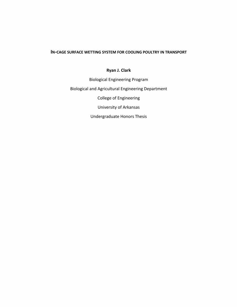
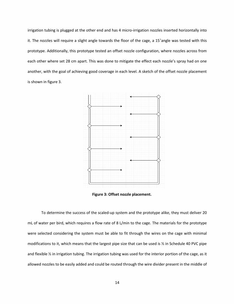
irrigation tubing is plugged at the other end and has 4 micro-irrigation nozzles inserted horizontally into
it. The nozzles will require a slight angle towards the floor of the cage, a 15˚angle was tested with this
prototype. Additionally, this prototype tested an offset nozzle configuration, where nozzles across from
each other where set 28 cm apart. This was done to mitigate the effect each nozzle’s spray had on one
another, with the goal of achieving good coverage in each level. A sketch of the offset nozzle placement
is shown in figure 3.
To determine the success of the scaled-up system and the prototype alike, they must deliver 20
mL of water per bird, which requires a flow rate of 8 L/min to the cage. The materials for the prototype
were selected considering the system must be able to fit through the wires on the cage with minimal
modifications to it, which means that the largest pipe size that can be used is ½ in Schedule 40 PVC pipe
and flexible ½ in irrigation tubing. The irrigation tubing was used for the interior portion of the cage, as it
allowed nozzles to be easily added and could be routed through the wire divider present in the middle of
Figure 3: Offset nozzle placement.

15
the cage. Installed on the prototype was a pressure gauge that allowed pressure within the system to be
monitored for testing. However, this would be part of the control panel on the commercial system. Also,
in contrast with the commercial system, the prototype was directly attached to a 1/6 hp submersible
pump (model RL-MP16) for testing. Figures 4 and 5 show how the prototype is mounted with zipties on
the poultry transport cage.
Figure 4: Prototype PVC skeleton attached to the side of the cage,
with irrigation tubing extending into levels 3 and 4.

16
Adjustable micro-irrigation nozzles were used in the prototype for testing, allowing the conical
spray to be adjusted to optimize the coverage within each level. The main consideration while building
the prototype was a nozzle placement within the two levels of the cage that would allow the middle of
the cage to be sprayed consistently. The best method identified for this was to place irrigation tubing on
both sides of the cage attached to the support beams, with the nozzles pointed horizontally inwards and
angled approximately 15˚ towards the floor of the cage as shown in figure 6. Nozzles were also offset as
sketched in figure 3 to provide good coverage in the two levels tested.
Figure 5: Irrigation tubing with nozzles installed at a 15˚angle towards
the floor of the cage. Interior of the cage, door side.

17
5. Materials
The materials selected for this project are commercially available and easily acquired. The prototype
consists mainly of ½ in PVC pipe and ½ in irrigation tubing, which will fit through the wires of the cage with
minimal modifications. The nozzles are adjustable micro-irrigation nozzles that provide a conical spray
and are able to operate at lower pressures, such as the 10 psi necessary for this system. A 1/6 hp
submersible pump was used to provide the appropriate flow rate into the prototype. However, for the
scaled-up model, a single pump would be installed on the transport truck and be sized to provide the
appropriate flow rate to all cages through a network of pipes and quick-disconnects. A detailed list of the
parts required to build the prototype is shown in table 2, followed by a detailed list of the parts necessary
for a scaled-up system to spray all five levels in table 3.
Figure 6: Side view of irrigation tubing showing nozzle
placement with a 15˚angle towards cage floor.

18
Table 2: Materials for prototype build to equip two levels in the cage.
Item: Quantity:
½ in Irrigation Tubing 9.72 m
½ in Schedule 40 PVC Pipe 3.63 m
½ in PVC Threaded T-fittings 3
½ in PVC Elbow 4
Micro-irrigation Nozzles 16
½ in PVC to Irrigation Tubing Adapters 4
½ in Irrigation Tubing Plugs 4
1/6 hp Submersible Pump model RL-MP16 1
Table 3: Materials for scaled-up system to equip all five levels in one cage.
Item: Quantity:
½ in Irrigation Tubing 24.3 m
½ in Schedule 40 PVC Pipe 3.63 m
½ in PVC Threaded T-fittings 9
½ in PVC Elbows 3
Micro-irrigation Nozzles 40
½ in PVC to Irrigation Tubing Adapters 10
½ in Tubing Plugs 10
Retractable hose 1
19
6. Design Calculations
The main calculations necessary for this design are to size the piping system so that the
system is able to deliver 20 mL of water per bird per spray. This means that each cage must
receive 2 L of water, requiring a flow rate of 8 L/min (refer to appendix A for calculations
spreadsheet). This flow rate is based on a 15 second spray duration, which is the minimum
amount of time necessary for the nozzles to achieve full flow and deliver the required amount of
water. The flow rate was halved when sizing each side of the PVC skeleton, as this is the amount
of water that each side will need to transport.
For the prototype an initial spreadsheet (appendix A) was made to size the system and the
pump that would provide the desired flowrate and that could overcome the additional head
caused by the desired pressure of 10 psi. To ensure the selected pump (RL-MP16 1/6 hp
submersible pump) would be adequate to test the prototype, a system curve and pump curve
were developed, shown in figure 7.

20
A nozzle K value of 1.5 was assumed initially to calculate friction loss through the nozzles. This
K value was later changed to 3.5 after some testing with the adjustable nozzles installed on the
prototype. The measured K value was determined from the flow rate provided by the nozzles,
and the size of the orifice of the nozzles.
Calculations for the scaled-up system were done after testing the prototype (appendix A).
Since the pressure for this system is still set at 10 psi, the only change is the additional friction
losses caused by the 6 additional branches of the system.
Figure 7: Graph of system curve vs. pump curve for the prototype
determined from total work required calculations. Intersect of the curves
indicates the operating point of the prototype.

21
Experimental Design
Testing of the prototype was done on a poultry transport cage to ensure proper fit and functionality.
A layer of roofing paper was placed on the floor of the levels being tested so that water coverage within
each level could be visualized. Toilet paper rolls were used to simulate broiler chickens inside the cage.
Twelve toilet paper rolls were used in each level, placed evenly in each of the four sections in a 6 x 2 grid
pattern, approximately 30 cm apart. Each of the four sections was recorded as a separate data set. The
dry weight of six of the rolls was recorded before they were sprayed so that an average roll weight could
be calculated. This average roll weight was used to calculate the increase in weight caused by the water
for all of the rolls. After a spray cycle of 15 seconds, the average weight of the rolls was recorded again.
Another reason for placing the rolls in a grid was to determine if the presence of chickens in the cage
would drastically affect coverage within the cage. The testing included two 15 second spray intervals to
determine if the system was able to deliver enough water to cool the broiler chickens. Food coloring was
added to the water to increase the visibility of the spray. Additionally, a pressure gauge was placed at the
end of the pipe on the fourth level so that pressure in the system could be monitored. Roll position and
designation is mapped in figure 8.

22
Results
Coverage within the cage was excellent and is estimated to be over 75% of the levels tested.
Droplet size and coverage was observed on the roofing paper that was laid on the tested levels. The middle
of each level received the most amount of water, which is beneficial since this is the area that would be
expected to be a hot spot. Reach of the spray was between 36 cm and 76 cm from the nozzle. The edges
of the cage received the least amount of water, getting sprayed only as the system was turned on or shut
down. This is the area of least concern, as it receives the most airflow while the truck is moving. It is
Figure 8: Position of toilet paper rolls in one
level of the cage with numbered roll position.

23
important to note that nozzle angles are essential to the proper functioning of the system. Some of the
nozzles got twisted upwards, causing them to spray the roof more than the rolls in the cage. Another
significant observation is that after only two 15 second test intervals there was significant pooling on the
cage floor. Figure 9 shows the cage before spraying and figure 10 shows the pooling of water on the floor
after only two test intervals.
Figure 9: Cage floor before spray cycle.

24
The test with the toilet paper rolls that simulated broiler chickens produced a wide range of
results. Although most of the outlying values can be attributed to a poorly placed nozzle or absorption
from the pooling that occurred on the cage floor. Elevating the rolls off the cage floor would help mitigate
the error caused by the pooling in future tests. However, this test was significant as it proved that the
average amount of water delivered to the rolls was 17.4 mL from a 15 second spray, which was within the
acceptable range of 15 to 20 mL for cooling the chickens in the cage. It also proved the system was sized
appropriately, since each sections data set was recorded separately, and the water delivered to each was
similar in quantity. There was only one section that received more water than intended, and that was the
fourth level on the left-hand side. The reason for this was the adjustment on the nozzle heads allowed a
higher flow rate than the nozzles on the rest of the system. Figure 11 shows box and whisker plots for
each section, showing the water delivered to the rolls. Figure 12 shows a box and whisker plot that shows
the distribution for the entire system during a single cycle.
Figure 10: Cage floor after two spray cycles with significant pooling.

25
Figure 11: Water delivered to rolls in four sections (two levels) of the cage
after a 30 second spray.
Figure 12: Distribution for water delivered to entire system during 15
second spray.

26
These charts show the variability of water distribution as a result of four adjustable nozzles in
each section of the cage. Also, figure 11 shows water delivered to rolls after two spray cycles, or 30
seconds of spraying. The mean for all four sections is similar and within the 15 to 20 mL goal, although
several outliers may have skewed these values slightly. However, if the outliers are removed from the
data set, the mean values for each section normalize. This proves that the rolls that consistently received
more water, did so because of the nozzle they were placed in front of, and not because of fluctuations in
the performance of the system.
Testing of the prototype revealed that the system is functional and will provide enough water to
cool broiler chickens during transport, with droplet sizes large enough so as to not evaporate away too
quickly. The minimum spray interval was confirmed to be 15 seconds, as anything less than this does not
allow the system to reach a pressure high enough for the nozzles to reach the expected hot spots in the
middle of the cage. Nozzle placement and angle were confirmed to work on the nozzles that were placed
correctly. A consequence of nozzles that were angled to high was pooling, as the spray pattern would hit
the roof of the level and then drip down. The system was unobtrusive in the cage, as it can be mounted
adjacent to the floor supports that hold the next level up. More testing would be beneficial to further
optimize the system. Also, a test that uses toilet paper rolls at the loading density of each level (20 broiler
chickens per section of the cage) would also provide useful data for further analysis of the system.
Economic Analysis
The following economic analysis represents the cost and payback period of the entire cooling
system on a single truck. The system is intended to run during the hottest months of the summer; from
May to August. Several assumptions had to be made to determine capital cost and payback period of the
system, as well as the effect of the additional water weight on gas mileage of the transport truck. These
assumptions are listed below:

27
• Average weight of broiler chicken= 5 lb
• Average carcass value= $0.75/lb
• Current mortality rate per truck load= 0.4%
• Mortality rate with cooling system= 0.1%
• Truck loads per day= 5 loads/day
• Cage loading= 200 chickens/cage
• Cages on truck= 20 cages/truck
• Cost of pumping and piping system on truck= $2000
• Months system is in use= 4 months
• Maximum amount of spray cycles per 2 hr trip= 24 sprays
• Weight of a single cage= 150 lb
• Loaded truck weight without spray system=53,000 lb
• Loaded truck weight with spray system=55,500 lb
• Current gas mileage= 6 mpg
• Gas mileage reduction with system= -0.08 mpg
• Value of diesel= $3.00/gal
• Miles driven with full reservoir= 300 miles/day

28
Table 4 shows the materials required to build a full system for one cage, as well as the cost per
unit of each material and the cost to outfit an entire truck loaded with 20 cages.
Table 4: Materials for scaled-up system to equip all five levels of a cage with unit costs and the
cost to outfit 20 cages on a truck.
Item: Quantity
per Cage:
Cost per Unit: Cost for System: Source:
½ in Irrigation Tubing 24.3 m $0.10 per 0.3m $162 for 486 m Amazon.com
½ in Schedule 40 PVC Pipe 3.63 m $2.20 per 3.048m $54.5 for 72.5 m Home Depot
½ in PVC Threaded T-fittings 9 $0.83 per unit $149.4 for 180 units Home Depot
½ in PVC Elbows 3 $0.59 per unit $35.4 for 60 units Home Depot
Micro-irrigation Nozzles 40 $9.89 for 12 units $659.3 for 800 units Amazon.com
½ in PVC to Irrigation Tubing
Adapters
10 $4.21 per unit $842 for 200 units Amazon.com
½ in Tubing Plugs 10 $4.35 per unit $870 for 200 units Amazon.com
Pumping System for Truck 1 $2000 $2000 for 1 unit Assumed value
Total Cost to Outfit One Truck $4,772.6

29
With a capital cost of $4,772.6 to outfit one truck with this spray system and an average mortality rate
reduction of 0.3% from current values during the summer months; the payback period is calculated as
follows.
𝐶ℎ𝑖𝑐𝑘𝑒𝑛𝑠 𝑙𝑜𝑠𝑡 𝑝𝑒𝑟 𝑙𝑜𝑎𝑑 = 4000 𝑐ℎ𝑖𝑐𝑘𝑒𝑛𝑠 ∗ 0.003 = 12 𝑐ℎ𝑖𝑐𝑘𝑒𝑛𝑠
𝐸𝑐𝑜𝑛𝑜𝑚𝑖𝑐 𝑙𝑜𝑠𝑠 𝑝𝑒𝑟 𝑑𝑎𝑦 = (12 𝑐ℎ𝑖𝑐𝑘𝑒𝑛𝑠/𝑙𝑜𝑎𝑑 ∗ 5 𝑙𝑜𝑎𝑑𝑠/𝑑𝑎𝑦) ∗ (5 𝑙𝑏
𝑐ℎ𝑖𝑐𝑘𝑒𝑛∗
$0.75
𝑙𝑏) = $225/𝑑𝑎𝑦
𝑂𝑝𝑒𝑟𝑎𝑡𝑖𝑛𝑔 𝑐𝑜𝑠𝑡 𝑖𝑛𝑐𝑟𝑒𝑎𝑠𝑒 = [(300𝑚𝑖𝑙𝑒𝑠
5.92𝑚𝑝𝑔) ∗ (
$3.00
𝑔𝑎𝑙)] − [(
300𝑚𝑖𝑙𝑒𝑠
6𝑚𝑝𝑔) ∗ (
$3.00
𝑔𝑎𝑙)] = $2.03
𝑆𝑖𝑚𝑝𝑙𝑒 𝑃𝑎𝑦𝑏𝑎𝑐𝑘 𝑃𝑒𝑟𝑖𝑜𝑑 =$4,772.6
$225𝑑𝑎𝑦
−$2.03𝑑𝑎𝑦
= 21.4 𝑑𝑎𝑦𝑠
This payback period does not account for the economic gains possible if the system were to
reduce shrinkage of the broiler chickens during transport and the benefits of a reduced microbial load if
a biocide were to be added to the water. However, even with the rough estimate provided above, the
payback period for the system is 22 days just from the reduction in mortality rates during the live-haul
process.
Discussion and Future Opportunities
Reducing mortality rates in chickens during the live-haul process will prevent a valuable resource
from being wasted. This project has provided an opportunity to do just that, as well as providing insights
into what can be improved for the next iteration. The materials used for this project would be adequate
for a commercial model of this system. All except the nozzles worked well. Using irrigation tubing inside
the cage allows for easy replacement or addition of nozzles, or the replacement of the entire tubing
section. It also eliminates the time needed for PVC cement to cure and does not require the entire system

30
to be rebuilt in case of minor damage. The entire system could be built out of ½ in PVC pipe, but additional
modifications to the cage would be required to fit the rigid piping. My recommendation for future nozzle
selection is to use a micro-irrigation nozzle that will function at a pressure around 10 psi, but that does
not have an adjustable head. The cone shaped spray pattern worked well, and I would recommend this
spray pattern for future iterations.
Nozzle placement in this system provided great coverage in areas of the cage that were the
highest concern. However, it was evident that the angle at which the nozzles are placed is essential to the
proper functioning of the system and to the consistency of water delivered to these areas, so care should
be taken to place them at a 15˚angle towards the floor of the cage. It is also worth exploring the placement
of 12 nozzles per level rather than 8 nozzles, as this could further increase the coverage provided on each
level. This is especially important if the sections on the cage are loaded with up to 20 broiler chickens. The
design pressure of 10 psi was also proven to be adequate for the system. Having a lower pressure allows
micro-irrigation nozzles to be used, making the system economically viable and user friendly. This pressure
also prevents injury to the birds closest to the nozzles, as well as to the operators in case any point of the
system failed.
Psychrometrics are an important part of determining how often the system should be run during
transportation. The frequency of spraying should be determined based on outside temperature and
humidity to ensure that sprayed water can evaporate before a subsequent spray. A control unit will
activate the pump at certain intervals based on these calculations so that the chickens remain cool. This
aspect of the project needs to be explored for the implementation of this system to be effective and safe.
Future work for this project, and an essential part of this system that was not designed, is a truck-
mounted water reservoir and pumping system along with the necessary controls and connections to the
modules. The cage-mounted module that was designed and sized for this project will have a quick-

31
disconnect on a retractable hose that leads into the pipe that would deliver water to all the cages loaded
on the truck. This would allow the delivery system to remain on the cage during loading and unloading
processes and does not restrict where each cage may be placed on the flat-bed trailer. However, the
addition of this system will require that the cages to be loaded in a way that places all the connection
points on the side of the truck-mounted piping system that will deliver water to each cage. It is not
expected that loading and unloading times will be drastically changed by the implementation of this
system. Quantifying the impact of the additional 1000 L water that will need to be carried, with a weight
of 2,200 lb, on the truck’s gas mileage is difficult. In the economic analysis the decrease in gas mileage
was kept constant. However, as the water gets sprayed the truck would lose some of the water weight it
is carrying, making the effect on its gas mileage change over time. Designing the truck-mounted portion
of the system will require sizing and placing a water reservoir on the underside of the flat-bed trailer. A
pump and main pipe would also need to be sized and placed to allow all 20 cages to receive the stated
flowrate. Controls for the system will also need to be selected and a power source provided for the pump
and controls.
Future work for this project would also include implementing this system on a fleet of trucks and
recording its effect on mortality rates during the live-haul process during the summer months. In theory
this system would reduce mortality, just as similar systems have done in grow houses. However, it’s
implementation in an uncontrolled environment such as the transportation cages has not been tested on
live birds, and environmental factors could have an influence on its effect that may not have been
accounted for. The use of a biocide in the water reservoir of this system should also be considered, as it
could reduce the microbial load of broiler chickens entering the processing facility. A reduction in the rate
of shrinkage of the broiler chickens cause by their thermoregulation during the transportation process is
also expected but should be quantified with further research and testing.

32
This design is only the beginning of a system that could provide poultry companies with a
reduction in economic losses and consumers with an increase in product quality. With the possibility of
reducing microbial loads and shrinkage rates during the live-haul process, this system could allow poultry
companies to achieve their goal of reducing mortality rates to just 0.1%, increase the welfare of their
animals, and maximize their profits simultaneously. On a larger scale, improving the food chain by
reducing wasted product means the poultry industry becomes more sustainable.
33
Acknowledgements
Dr. Yi Liang for her guidance throughout this project and for her help in the testing of the prototype.
Dr. Thomas Costello for his help selecting and acquiring the nozzles necessary for the completion of this
project.
Dr. Brian Haggard for his help in developing this honors thesis into a document that not only met the
prerequisites, but that could also be a document I can be proud of.
Dr. Scott Osborn for teaching me the skills that were essential to this design and for his continued help
in sizing the system accurately.
Prof. Mark Christie for sharing his knowledge about the poultry industry and for reviewing this report on
multiple occasions.
Biological Engineering Department for the help and encouragement I received from the faculty and staff
to be able to complete this honors thesis.

34
References
Agri Stats, Inc. (1997-2003). Processing Analysis Data. Fort Wayne,IN.
C. W. Ritz, A. B. Webster, M. Czarick III. (2005). Evaluation of Hot Weather Thermal Environment and
Incidence of Mortality Associated with Broiler Live Haul. Poultry Science Association, Inc.
M. Petracci, M. Bianchi, C. Cavani, P. Gaspari, A. Lavazza. (2006). Preslaughter Mortality in Broiler
Chickens, Turkeys, and Spent Hens Under Commercial Slaughtering. Poultry Science 85, 1660-
1664.
P.D. Warriss, A. Pagazaurtundua, S.N. Brown. (2005). Relationship Between Maximum Daily
Temperature and Mortality of Broiler Chickens during Transport and Lairage. British Poultry
Science 46:6, 647-651.
S. Mutaf, N. Seber Kahraman, M. Z. Firat. (2008). Surface Wetting and Its Effect on Body and Surface
Temperatures of Domestic Laying Hens at Different Thermal Conditions. Poultry Science 87,
2441-2450.
Seger, J. (2009, June 6). Fuel Economy vs. Payload. BENG 3653. Cummins, Inc.
USDA-NASS. (2003). Poultry production and value 2003 summary. Retrieved from
http://www.usda.gov/nass/
X. Tao, H. Xin. (2002). Surface Wetting and its Optimization to Cool Broiler Chickens. ASAE 46, 483-490.
Y. Liang, G. T. Tabler, T. A. Costello, I. L. Berry, S. E. Watkins, Y. V. Thaxton. (2013). Cooling Broiler
Chickens by Surface Wetting: Indoor Thermal Environment, Water Usage and Bird Performance.
ASABE 30, 249-258.

35
Appendix A
Prototype Calculations
Q (L/min) 8 PVC Area (m2) 0.000201 Re 5.38E+03 F1-2 (m) 0.098
Q (m3/s) 0.000133 Velocity 1 (m/s) 0.332 Ԑ/D 0.000094 F1-3 (m) 0.095
ρ (kg/m3) 998 v2 (m2/s2) 0.110 ƒ 3.69E-02
μ (Pa*s) 9.84E-04 Velocity 2 (m/s) 0
Pressure 1 (Pa) 58605.4 Fsp 1-2 (m) 0.048
Pressure 2 (Pa) 0 Fsp 1-3 (m) 0.051
Length PVC1-2 (m) 1.3 Gravity (m/s2) 9.81
Length PVC1-3 (m) 1.54
Length Tubing (m) 2.43 W1-2 (m) 7.108
h1 (m) 0.72 W1-3 (m) 0.147
h2 (m) 0.97 Wtotal (m) 7.255
1/2 in PVC ID (m) 0.016
T-fitting XA K 1.5
T-fitting XB K 0.5 Pdel (W) 9.470
Elbow K 0.5 Pdel (hp) 0.013
Nozzle K 3.5
Q (L/min) Q (m3/s) Work (m)
1 1.7E-05 6.962
2 3.3E-05 6.979
3 5.0E-05 7.005
4 6.7E-05 7.041
5 8.3E-05 7.086
6 1.0E-04 7.140
7 1.2E-04 7.202
8 1.3E-04 7.255
9 1.5E-04 7.354
10 1.7E-04 7.442
Q (L/min) Q (m3/s) Work (m)
34.83 0.000581 6.096
0 0 7.8
Fittings Friction
Work Calculations
Power Delivered
System Curve
Pump Curve (Eff=4%)
Liquid Properties
System Properties
Operating Values Straight Pipe Friction
0.000
1.000
2.000
3.000
4.000
5.000
6.000
7.000
8.000
9.000
0 5 10 15 20 25 30 35 40
Wo
rk (
m)
Q (L/min)
System Curve vs. Pump Curve
System Curve Pump Curve
Pump used is the RL-MP16 submersible pump (1/6 hp).V=115V and I=2A

36
Scaled-up System Calculations
Q (L/min) 8 PVC Area (m2) 0.000201 Re 5383.374 F1-1 (m)= 0.093
Q (m3/s) 0.000133 Velocity 1 (m/s) 0.332 Ԑ/D 0.000094 F1-2 (m)= 0.101
ρ (kg/m3) 998 v2 (m2/s2) 0.110 ƒ 0.03695 F1-3 (m)= 0.104
μ (Pa*s) 0.000984 Velocity 2 (m/s) 0 F1-4 (m)= 0.107
Pressure 1 (Pa) 58605.4 Fsp 1-1 (m)= 0.035 F1-5 (m)= 0.104
Pressure 2 (Pa) 0 Fsp 1-2 (m)= 0.038
Length PVC1-1 (m) 2.684 Gravity (m/s2) 9.81 Fsp 1-3 (m)= 0.041
Length PVC1-2 (m) 2.938 Fsp 1-4 (m)= 0.045
Length PVC1-3 (m) 3.192 Fsp 1-5 (m)= 0.048
Length PVC1-4 (m) 3.446
Length PVC1-5 (m) 3.7
h1 (m) 0.254 W1-1 (m)= 0.127 Pdel (W)= 10.412
h2 (m) 0.508 W1-2 (m)= 0.139 Pdel (hp)= 0.014
h3 (m) 0.762 W1-3 (m)= 0.145
h4 (m) 1.016 W1-4 (m)= 0.151
h5 (m) 1.27 W1-5 (m)= 7.413
1/2 in PVC ID (m) 0.016 WTotal (m)= 7.976
T-fitting XA K 1.5
T-fitting XB K 0.5
Elbow K 0.5
Nozzle K 3.5
Work Calculations Power Delivered
Fittings FrictionLiquid Properties Operating Values
System Properties
Straight Pipe FrictionScaled-up calculations are for a single cage system that will spray all five levels. Includes 8 nozzles per level of the cage. Accounts for the same materials used in the prototype, which include 1/2 in PVC pipe and 1/2 in irrigation tubing.

37
Testing Data and Analysis
Water Delivered to Rolls 1 2 3 4 5 6 Mean
Pre-wetting Roll Weight (g)= 71 72 70.4 70.6 74.4 72.7 71.85
Wet Roll Weight 4L (g)= 138 80.4 213 81.2 84.1 148.9 124.2667
Wet Roll Weight 4R (g)= 91.8 102.6 97.1 109.8 130.1 106.1 106.25
Wet Roll Weight 3L (g)= 150.3 73.8 98.1 97.7 76.3 72.1 94.71667
Wet Roll Weight 3R (g)= 92.2 82.8 120 100.9 99.9 112.2 101.3333
Water Delivered to Roll 4L (mL)= 66.15 8.55 141.15 9.35 12.25 77.05 52.41667
Water Delivered to Roll 4R (mL)= 19.95 30.75 25.25 37.95 58.25 34.25 34.4
Water Delivered to Roll 3L (mL)= 78.45 1.95 26.25 25.85 4.45 0.25 22.86667
Water Delivered to Roll 3R (mL)= 20.35 10.95 48.15 29.05 28.05 40.35 29.48333
Mean Total (mL)= 34.79166667 *30 s spray
Av. water delivered per cycle (mL)= 17.39583333 *15 s spray
Total Water Delivered to Rolls (mL)= 835
Water Delivered from Bucket
Initial Weight (kg)= 15.98
Final Weight (kg)= 14.01
Water Used (kg)= 1.97
Water Used (m3)= 0.001973948
Water Used (mL) 1970
Run Time (s)= 31
Prototype nozzle K Calculations
Initial Container Weight (g)= 60.1 60.4
Final Container Weight (g)= 140 183.5
Run Time (s)= 20.33 21.12
Pressure (psi)= 8.5 8.5
Pressure (Pa)= 58605.46 58605.46
PVC Area (m2)= 0.000000785 7.85E-07
Q (m3/s)= 3.93015E-06 5.8286E-06
v (m/s)= 5.006563674 7.42496622
v2 (m2/s2)= 25.06567982 55.1301234
K Nozzle= 4.685522693 2.13033827
The table to the right contains data from the testing of the prototype. The pre-wetting wight of the toillet paper rolls is recorded for 6 rolls and then averaged. The wet weight was taken for each roll, in each section of the cage, each section has a number and letter to designate the location in the cage. The number corresponds to the level of the cage, and the L or R letter corresponds to the side of the cage. The wetted values that are recorded are for two 15 second runs of the prototype, so values must be halved to get a "per run" basis.
The system delivered 835 mL to the rolls, as measuered from the rolls. The measurement from the bucket indicates that 1,970 mL was delivered to the system. This means the rolls received approximately 42% of the water delivered.
Since the prototype was built using adjustable nozzles, a K value needed to be calculated from the data tha could be gathered. From the two tests run on a single nozzle, the K value is estimated to be 3.5

38

39