Embed Size (px)
Citation preview
Infr
ast
ruct
ure
for
LHC
b U
pgra
de w
ork
shop
–
M
UO
N d
ete
ctor
Infrastructure for LHCB Upgrade workshop:MUON power, electronics, cable
• Muon upgrade in a nutshell
• LV power scheme
• HV power scheme
• Optical fibers connections
• Conclusions
Paolo CiambroneAlessandro Cardini
for the muon group
Infr
ast
ruct
ure
for
LHC
b U
pgra
de w
ork
shop
–
M
UO
N d
ete
ctor
219/02/2015
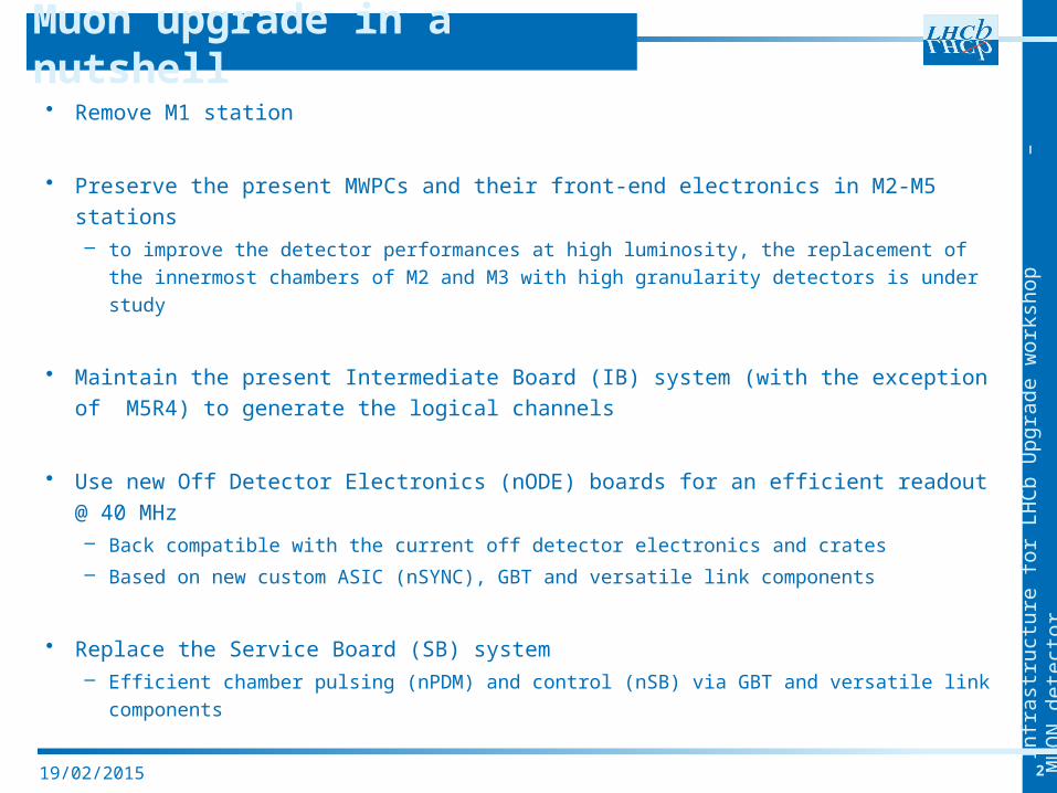
• Remove M1 station
• Preserve the present MWPCs and their front-end electronics in M2-M5 stations– to improve the detector performances at high luminosity, the replacement of the
innermost chambers of M2 and M3 with high granularity detectors is under study
• Maintain the present Intermediate Board (IB) system (with the exception of M5R4) to generate the logical channels
• Use new Off Detector Electronics (nODE) boards for an efficient readout @ 40 MHz– Back compatible with the current off detector electronics and crates
– Based on new custom ASIC (nSYNC), GBT and versatile link components
• Replace the Service Board (SB) system– Efficient chamber pulsing (nPDM) and control (nSB) via GBT and versatile link
components
Muon upgrade in a nutshell
Infr
ast
ruct
ure
for
LHC
b U
pgra
de w
ork
shop
–
M
UO
N d
ete
ctor
319/02/2015
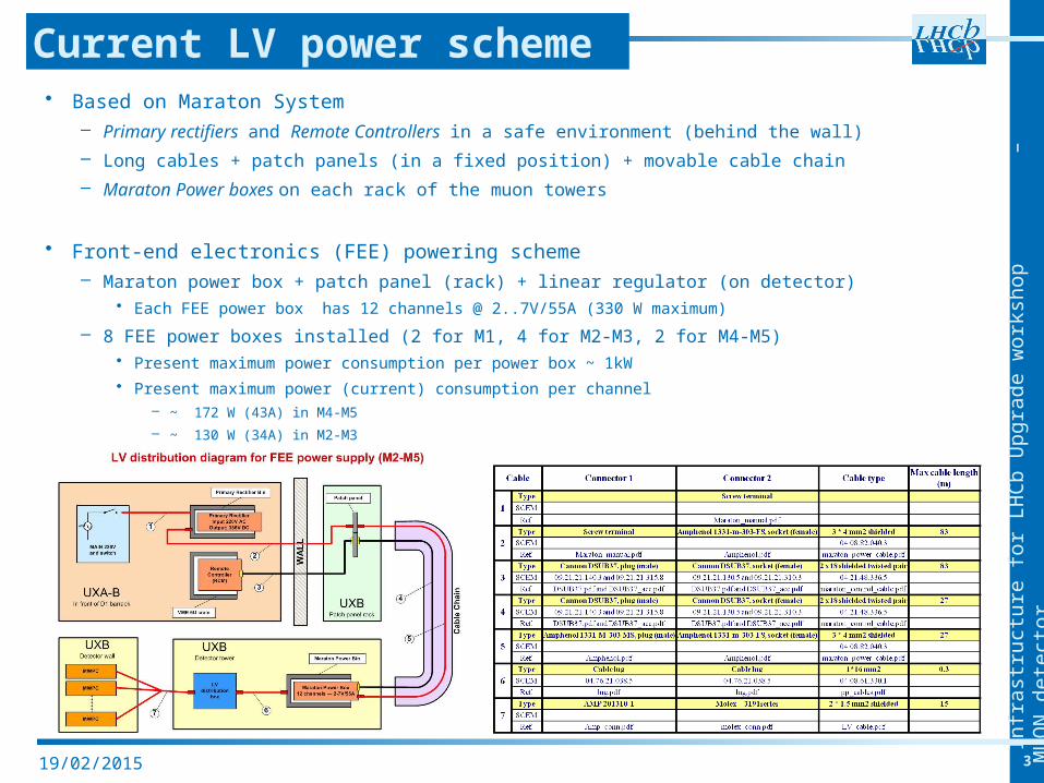
• Based on Maraton System– Primary rectifiers and Remote Controllers in a safe environment (behind the wall)
– Long cables + patch panels (in a fixed position) + movable cable chain
– Maraton Power boxes on each rack of the muon towers
• Front-end electronics (FEE) powering scheme– Maraton power box + patch panel (rack) + linear regulator (on detector)
• Each FEE power box has 12 channels @ 2..7V/55A (330 W maximum)
– 8 FEE power boxes installed (2 for M1, 4 for M2-M3, 2 for M4-M5)• Present maximum power consumption per power box ~ 1kW
• Present maximum power (current) consumption per channel – ~ 172 W (43A) in M4-M5
– ~ 130 W (34A) in M2-M3
Current LV power scheme
Infr
ast
ruct
ure
for
LHC
b U
pgra
de w
ork
shop
–
M
UO
N d
ete
ctor
419/02/2015
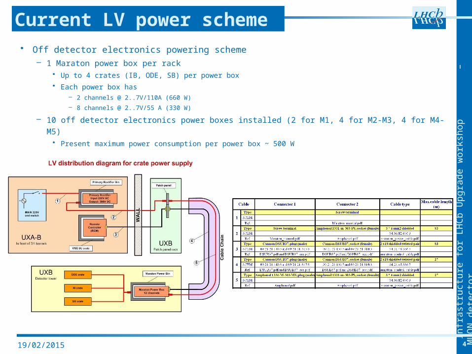
• Off detector electronics powering scheme– 1 Maraton power box per rack
• Up to 4 crates (IB, ODE, SB) per power box
• Each power box has – 2 channels @ 2..7V/110A (660 W)
– 8 channels @ 2..7V/55 A (330 W)
– 10 off detector electronics power boxes installed (2 for M1, 4 for M2-M3, 4 for M4-M5)• Present maximum power consumption per power box ~ 500 W
Current LV power scheme
Infr
ast
ruct
ure
for
LHC
b U
pgra
de w
ork
shop
–
M
UO
N d
ete
ctor
519/02/2015
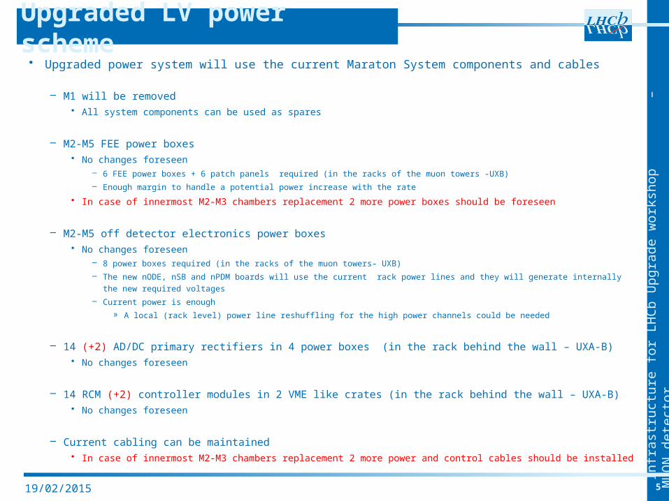
• Upgraded power system will use the current Maraton System components and cables
– M1 will be removed • All system components can be used as spares
– M2-M5 FEE power boxes• No changes foreseen
– 6 FEE power boxes + 6 patch panels required (in the racks of the muon towers -UXB)
– Enough margin to handle a potential power increase with the rate
• In case of innermost M2-M3 chambers replacement 2 more power boxes should be foreseen
– M2-M5 off detector electronics power boxes• No changes foreseen
– 8 power boxes required (in the racks of the muon towers- UXB)
– The new nODE, nSB and nPDM boards will use the current rack power lines and they will generate internally the new required voltages
– Current power is enough
» A local (rack level) power line reshuffling for the high power channels could be needed
– 14 (+2) AD/DC primary rectifiers in 4 power boxes (in the rack behind the wall – UXA-B)• No changes foreseen
– 14 RCM (+2) controller modules in 2 VME like crates (in the rack behind the wall – UXA-B)• No changes foreseen
– Current cabling can be maintained• In case of innermost M2-M3 chambers replacement 2 more power and control cables should be
installed
Upgraded LV power scheme
Infr
ast
ruct
ure
for
LHC
b U
pgra
de w
ork
shop
–
M
UO
N d
ete
ctor
619/02/2015
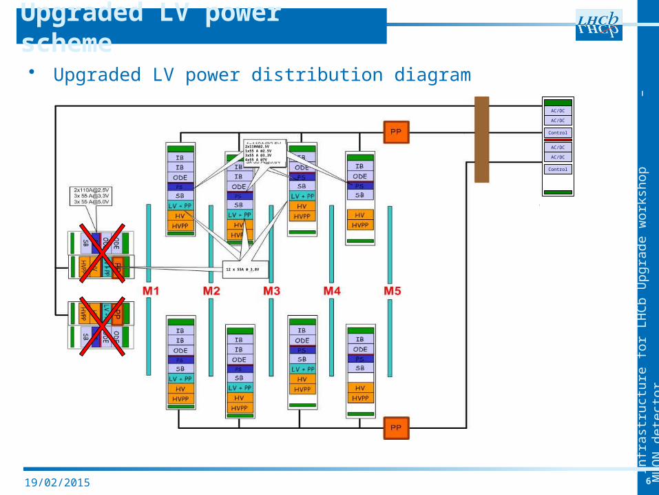
• Upgraded LV power distribution diagram
Upgraded LV power scheme
12 x 55A @ 3,8V
2x110A@2,5V1x55 A @2.5V3x55 A @3,3V4x55 A @7V
AC/DC
AC/DC
AC/DC
AC/DC
Control
Control
Infr
ast
ruct
ure
for
LHC
b U
pgra
de w
ork
shop
–
M
UO
N d
ete
ctor
719/02/2015
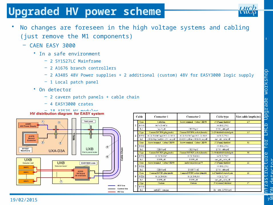
• No changes are foreseen in the high voltage systems and cabling (just remove the M1 components)– CAEN EASY 3000
• In a safe environment– 2 SY1527LC Mainframe
– 2 A1676 branch controllers
– 2 A3485 48V Power supplies + 2 additional (custom) 48V for EASY3000 logic supply
– 1 Local patch panel
• On detector– 2 cavern patch panels + cable chain
– 4 EASY3000 crates
– 18 A3535 HV modules
Upgraded HV power scheme
Infr
ast
ruct
ure
for
LHC
b U
pgra
de w
ork
shop
–
M
UO
N d
ete
ctor
819/02/2015
SY
1527
Mai
nfr
ame
A 1
676
con
tro
ller
s
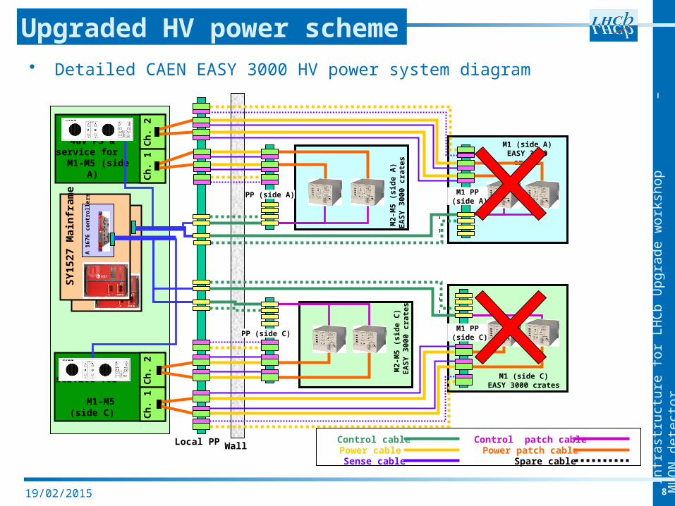
• Detailed CAEN EASY 3000 HV power system diagram
Upgraded HV power scheme
48V PS & service for
M1-M5 (side A)
Ch
. 2C
h. 1
48V PS & service for
M1-M5 (side C)
M1 (side A)EASY 3000 crates
PP (side C)
SY
1527
Mai
nfr
ame
A 1
676
con
tro
ller
s
M2-
M5
(sid
e A
) E
AS
Y 3
000
crat
esM
2-M
5 (s
ide
C)
EA
SY
300
0 cr
ates
M1 (side C)EASY 3000 crates
PP (side A)
Ch
. 2C
h. 1
Local PP Wall
M1 PP (side A)
M1 PP (side C)
Control cablePower cable
Control patch cable
Sense cable Spare cablePower patch cable
Infr
ast
ruct
ure
for
LHC
b U
pgra
de w
ork
shop
–
M
UO
N d
ete
ctor
919/02/2015
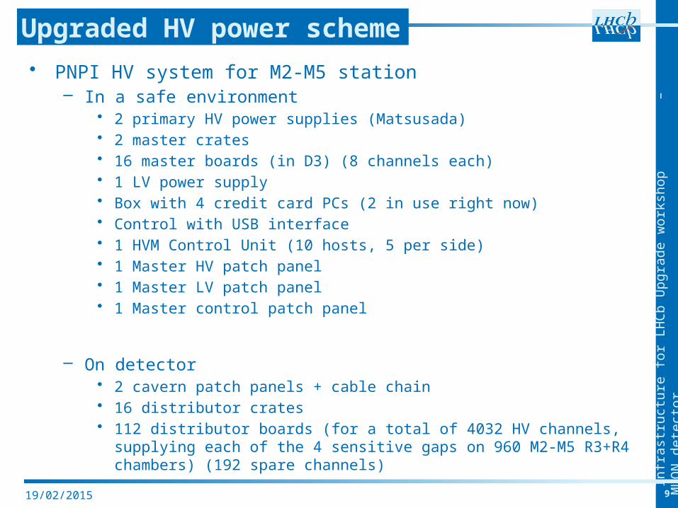
• PNPI HV system for M2-M5 station– In a safe environment
• 2 primary HV power supplies (Matsusada)• 2 master crates• 16 master boards (in D3) (8 channels each)• 1 LV power supply• Box with 4 credit card PCs (2 in use right now)• Control with USB interface• 1 HVM Control Unit (10 hosts, 5 per side)• 1 Master HV patch panel• 1 Master LV patch panel• 1 Master control patch panel
– On detector• 2 cavern patch panels + cable chain• 16 distributor crates• 112 distributor boards (for a total of 4032 HV channels, supplying
each of the 4 sensitive gaps on 960 M2-M5 R3+R4 chambers) (192 spare channels)
Upgraded HV power scheme
Infr
ast
ruct
ure
for
LHC
b U
pgra
de w
ork
shop
–
M
UO
N d
ete
ctor
1019/02/2015
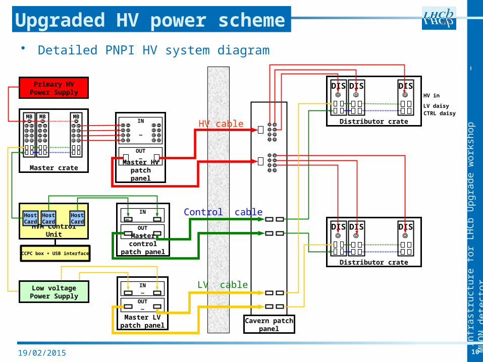
• Detailed PNPI HV system diagram
Upgraded HV power scheme
Master crate
HVM Control Unit
Primary HV Power Supply
MB
HostCard
HostCard
HostCard
Master HV patch panel
Master control patch
panel
MB MBIN
…
OUT…
OUT…
IN…
Master LV patch panel
OUT…
IN…
HV in
LV daisyCTRL daisy
Distributor crate
DIS DISDIS
Distributor crate
DIS DISDIS
Low voltage Power Supply
Cavern patch panel
HV cable
Control cable
LV cable
CCPC box + USB interface
Infr
ast
ruct
ure
for
LHC
b U
pgra
de w
ork
shop
–
M
UO
N d
ete
ctor
1119/02/2015
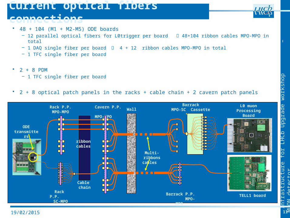
• 48 + 104 (M1 + M2-M5) ODE boards– 12 parallel optical fibers for L0trigger per board 48+104 ribbon cables MPO-MPO in total– 1 DAQ single fiber per board 4 + 12 ribbon cables MPO-MPO in total– 1 TFC single fiber per board
• 2 + 8 PDM– 1 TFC single fiber per board
• 2 + 8 optical patch panels in the racks + cable chain + 2 cavern patch panels
Current optical fibers connections
ODE transmitter
s
Rack P.P. MPO-MPO
Cavern P.P. MPO-MPO
Wall Barrack
MPO-SC Cassette
Multi- ribbons cables
L0 muon Processing
Board
ribbon cables
Rack P.P. SC-MPO
Barrack P.P. MPO-MPO
TELL1 board
Cable chain
Infr
ast
ruct
ure
for
LHC
b U
pgra
de w
ork
shop
–
M
UO
N d
ete
ctor
1219/02/2015
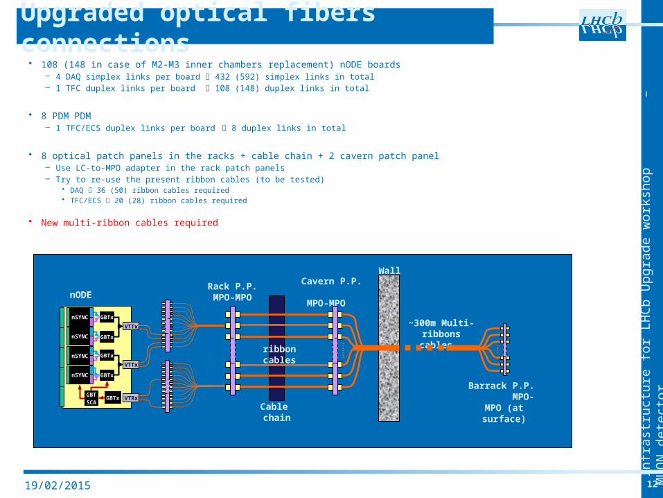
• 108 (148 in case of M2-M3 inner chambers replacement) nODE boards– 4 DAQ simplex links per board 432 (592) simplex links in total– 1 TFC duplex links per board 108 (148) duplex links in total
• 8 PDM PDM– 1 TFC/ECS duplex links per board 8 duplex links in total
• 8 optical patch panels in the racks + cable chain + 2 cavern patch panel– Use LC-to-MPO adapter in the rack patch panels– Try to re-use the present ribbon cables (to be tested)
• DAQ 36 (50) ribbon cables required• TFC/ECS 20 (28) ribbon cables required
• New multi-ribbon cables required
Upgraded optical fibers connections
nODERack P.P. MPO-MPO
Cavern P.P. MPO-
MPO
Wall
~300m Multi- ribbons cables ribbon
cables
Barrack P.P. MPO-MPO (at surface)Cable
chain
nSYNC
VTTx
GBTx
GBTx
VTTx
VTRxGBTSCA
nSYNC
nSYNC
nSYNC
GBTx
GBTx
GBTx
Infr
ast
ruct
ure
for
LHC
b U
pgra
de w
ork
shop
–
M
UO
N d
ete
ctor
1319/02/2015
• No change required in crates and racks on the muon towers
• No major change foresees for LV power system– Re-use present Maraton components for frond-end electronics
and off detector electronics power supply– Existing electrical power seems enough– Present cabling could be maintained– 2 new power boxes and cables should be installed in case of
innermost M2-M3 chambers replacement
• No change foresees for HV power system
• New multi-ribbons cables required for DAQ and TFC/ECS links– Try to re-use single ribbon cables from rack patch panels to
cavern patch panels
Conclusions