Embed Size (px)
Citation preview

INSTALLATION GUIDE
J-J Hooks Temporary Precast Barrier
© Copyright 2021 Easi-Set Worldwide - All rights reserved – 3/30/21 Page 1 of 12

INSTALLATION GUIDE
TABLE OF CONTENTS:
PURPOSE
PRODUCT DESCRIPTIONGeneralSelf-Aligning Connection Feature
HANDLING, SETTING, AND REMOVAL:
Suggested EquipmentLifting Device(s)Cranes and Lifts
Personnel Recommended for Installation/RemovalOff LoadingSettingRemovingLoading
Precautions/SafetySite Preparation
Face-of-Barrier LineSetting Area
Product DeliveryProduct UnloadingInstalling ProductRemoving ProductLoading Product
ANCHORING
Pinning/StakingTools Equipment Required Installation/Removal Process
BoltingTools Equipment Required Installation ProcessRemoval Process
© Copyright 2021 Easi-Set Worldwide - All rights reserved – 3/30/21 Page 2 of 12
PURPOSE:
This Guide provides some basic installation guidelines for the installation and removal of J-J Hooks TL3- NCHRP Report 350 & AASHTO MASH tested free-standing & restrained temporary, concrete barriers (TCB). It also contains ancillary information detailing its performance when tested to NCHRP 350 and MASH. Selected videos showing J-Hook connection engagement, setting, and removal are available for viewing at www.jjhooks.com.
As this Guide is updated, the pages/sections affected will contain a revision date in the lower left corner of the page(s).
PRODUCT DESCRIPTION:
General:
All J-J Hook barriers are a high strength, steel-reinforced, precast concrete safety barrier containing the J-J Hooks positive connection system. This connection system contains no loose hardware and the barrier end-design incorporates a self-aligning system for ease of installation and removal. Identical ends allow the barrier to be turned end-for-end when setting.
The J-J Hooks restrained (bolted) barrier provides easy installation requiring only 2 bolts for 12’ section, 3 bolts for 20’ section, and additional bolts for 30’ section. The bolts are reusable. The restrained (pinned/staked) barrier requires 3 pins/stakes for 12’ section, 4 pins/stakes for 20’ section, and for 30’ section additional pins/stakes per State DOT requirements/approvals.
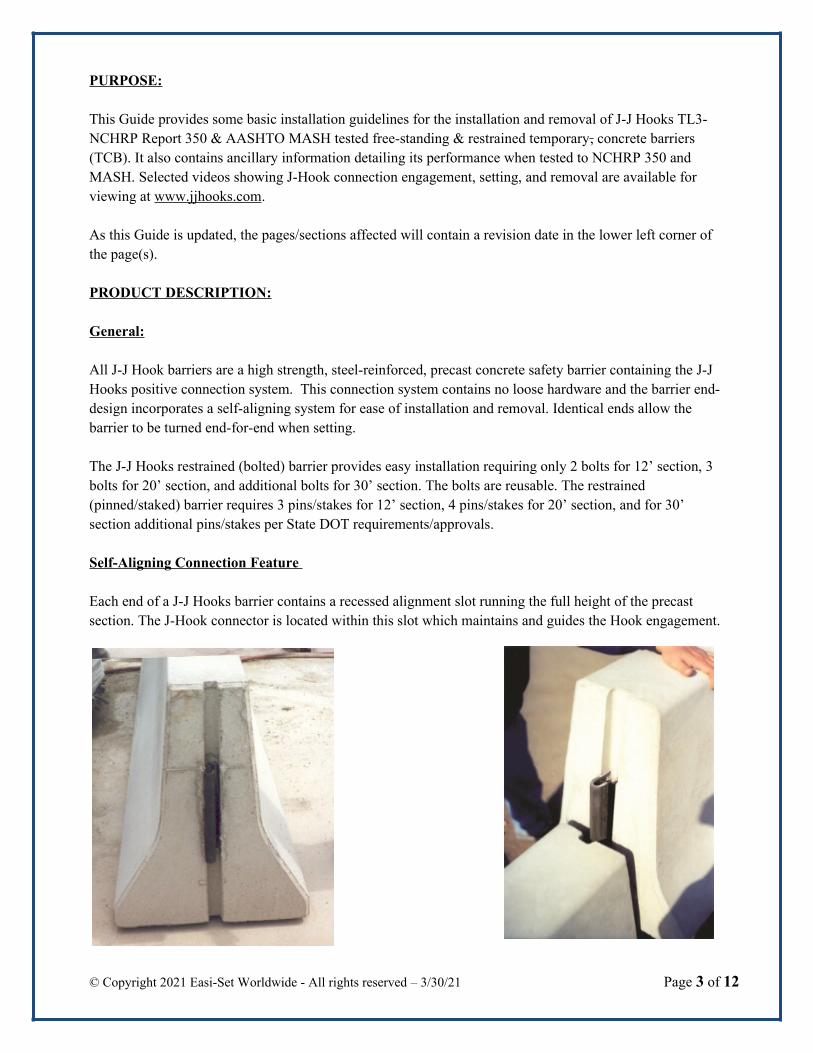
Self-Aligning Connection Feature
Each end of a J-J Hooks barrier contains a recessed alignment slot running the full height of the precast section. The J-Hook connector is located within this slot which maintains and guides the Hook engagement.
© Copyright 2021 Easi-Set Worldwide - All rights reserved – 3/30/21 Page 3 of 12
HANDLING, SETTING, AND REMOVAL
A visual inspection of each barrier segment is required prior to shipping. Should visible damage be evident in any segment, repairs should be made in accordance with the DOT guidelines for repairing temporary concrete barriers.
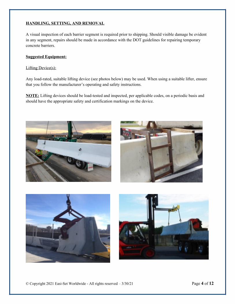
Suggested Equipment:
Lifting Device(s):
Any load-rated, suitable lifting device (see photos below) may be used. When using a suitable lifter, ensure that you follow the manufacturer’s operating and safety instructions.
NOTE: Lifting devices should be load-tested and inspected, per applicable codes, on a periodic basis and should have the appropriate safety and certification markings on the device.
© Copyright 2021 Easi-Set Worldwide - All rights reserved – 3/30/21 Page 4 of 12

Barriers Lifting, Setting and Retrieving Equipment
BACKHOE IN USE GRADALL IN USE
Typical Personnel Recommended for Installation/Removal at Work Site:
Off-Loading:
Recommendation– up to one (1) person on the trailer to attach the lifting device – this could be the truck driver or one of the barrier setting crew. Certain lifting devices may not require a person on the trailer.
Setting:
Recommendation – up to two (2) persons, one at either end of the suspended barrier, depending upon the length of barrier and lifting equipment being used. Experienced setting crews using certain lifting devices may choose to use only one person to guide/connect the suspended barrier.
Removing/Loading:
Recommendation - Reverse of instructions for Off-Loading / Setting
Precautions/Safety:
CAUTION: Prior to delivery/removal of barrier to/from the project, all associated personnel will have reviewed the DOT/provincial/etc. safety requirements, contract/job/site-specific safety requirements and, when appropriate, received safety training. All activities will also comply with applicable OSHA guidelines.
© Copyright 2021 Easi-Set Worldwide - All rights reserved – 3/30/21 Page 5 of 12

Site Preparation:
Setting Area:
Barriers should be placed on a flat, stable and compacted surface. Ideally the surface should be paved and free of swales, ditches or other irregularities.Align the segments according to the specified configuration and layout in the project traffic control plan.
Product Delivery:
Typically, precast concrete barrier are delivered on a flatbed trailer. Depending upon the shape and length ofthe barrier, a varying number of pieces can be placed on the trailer and remain within legal load limits.
Product Unloading:
The person on the trailer guides the lifting device toward the barrier to be lifted (as required depending uponlifting devices). The lifting device should be placed near the center-of-gravity of the barrier (typically near the center of the section). When it is lifted, the section should hang in a nearly level position.
NOTE: “Levelness” is one of the most important factors in easing the setting process.Then lift it from the trailer and move it toward the barrier installation area.
UNLOADING BARRIER FROM TRAILER
Installing Product:
The suspended barrier is moved toward the end of the last barrier section that has been set in the roadway installation.
The person(s) on the ground guide the suspended barrier into place. The connecting end is moved toward the already-set barrier
© Copyright 2021 Easi-Set Worldwide - All rights reserved – 3/30/21 Page 6 of 12

One end of the suspended barrier is guided over the J-Hook end of the set barrier. With the ends aligned, thesuspended barrier’s J-Hook connector is guided toward and over the set barrier’s cast-in alignment guide. As the barrier is lowered vertically, the J-Hooks automatically engage.
While the suspended barrier is being lowered with the J-Hooks engaged, the unconnected end is guided into place.
Barrier should be set in accordance with Traffic Control Plan Details.
Once the barrier is set and the lifting device is released it can be moved toward the trailer and attached to thenext barrier to be set.
BARRIER BEING INSTALLED
© Copyright 2021 Easi-Set Worldwide - All rights reserved – 3/30/21 Page 7 of 12
INSTALLATION HOOK ENGAGEMENT
Remove slack in hook engagement. (Permissible tolerance +0, -5/8 inch.

Removing and Loading Product on Trailer:
Reverse of instructions for Off-Loading / Setting
RESTRAINED J-J HOOKS BARRIERS - ROADWAY SURFACES ANCHORING:
Examples of roadway surfaces anchoring systems drilling equipment:
Manual Drill Multiple Heads Drill
ANCHORING
Pinning/Staking
Tools/Equipment Required
Hammer drill w 1 ½-inch diameter bit/w extension up 48” in length
Installation/Removal Process
When pinning/staking the J-J Hooks restrained barrier, the barriers are set in accordance with the Traffic Control Plan Details.
Once the barriers are placed, holes for receiving the 1 ½-inch diameter pin, 48” long are drilled through each pocket into the roadway on the traffic side. The pin is dropped into the receiving hole until the washer under the pin head “bottoms” in the pocket. When fully installed, the top of the pin should not project abovethe top of the pocket profile.
Removing the pin, requires that the removal device be attached to the top of the pin and then pulled out.
© Copyright 2021 Easi-Set Worldwide - All rights reserved – 3/30/21 Page 8 of 12

Note: Prior to bolting, validate the condition and strength of the existing deck concrete meets the requirements contained in the adhesive insert manufacturer’s product data.
Bolting:
Tools/Equipment Needed
Hammer drill with 1 3/8 -inch diameter bit 23-inches longWire brush Air hoseInserts 1” X 6”Hex head bolt 1” X 10”Plate washer 3” X 3” X 3/8” per testRetainer ring
© Copyright 2021 Easi-Set Worldwide - All rights reserved – 3/30/21 Page 9 of 12
As tested

Adhesive Hilti HIT HY 200Pressurized adhesive gunAir compressor – portable self-containedTorque wrenchOpen-end/box-end wrench for 1-inch hex boltHammerLarge screwdriverLarge pliersApproved Non-shrink grout (after barrier is removed)1-inch putty knife (for grout)
Installation Process (See Illustrations on Page 11)
Align the segments according to the specified configuration and layout in the project Traffic Control Plan Details.
Drill holes, through the bolt pocket, into the concrete deck or concrete pavements to allow 1”x 6” insert to be fully embedded into concrete.
Using the compressor and air hose, blow out the drilling residue from the hole
Clean hole with wire brush
Insert air nozzle to bottom of hole & blow out all dust and debris with compressed air.
Fill hole with adhesive about 2/3 full
Install the bolt insert, with the hex bolt threaded about half way into the insert. Washers should also be on the hex bolt at this point.
Allow adhesive to cure. Cure time to be in accordance with manufacturer’s recommendation. Do not disturbanchor during set and cure time.
Reinstall the hex bolt with the plate washer and retaining ring in place
Tighten hex bolt hand-tight and torque to 92.2 (125 n/m) foot pounds
Lift the retaining ring tab against the hex bolt flat to lock the bolt in place
Removal Process
Flatten the retaining ring tab.
Remove the hex bolt
Remove the barriers
Fill/Repair roadway surface in accordance to DOT guidelines
© Copyright 2021 Easi-Set Worldwide - All rights reserved – 3/30/21 Page 10 of 12

© Copyright 2021 Easi-Set Worldwide - All rights reserved – 3/30/21 Page 11 of 12

© Copyright 2021 Easi-Set Worldwide - All rights reserved – 3/30/21 Page 12 of 12