Embed Size (px)
Citation preview
835961-UIM-D-0213
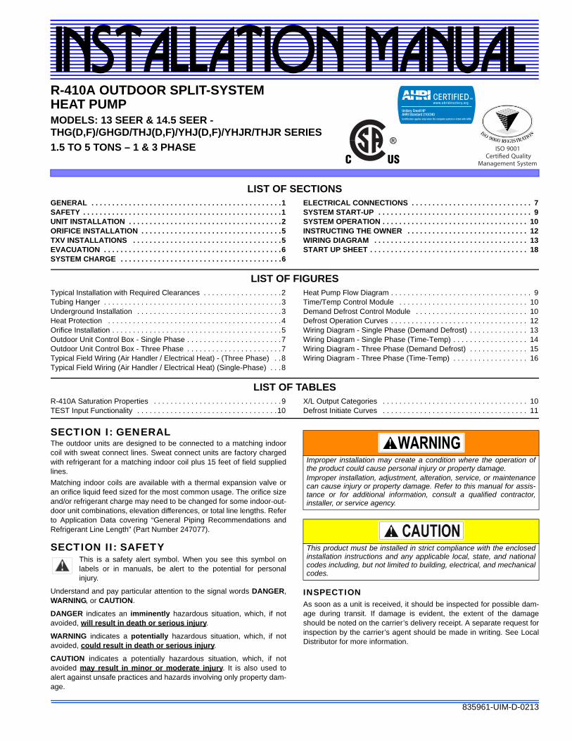
R-410A OUTDOOR SPLIT-SYSTEM HEAT PUMPMODELS: 13 SEER & 14.5 SEER - THG(D,F)/GHGD/THJ(D,F)/YHJ(D,F)/YHJR/THJR SERIES
1.5 TO 5 TONS – 1 & 3 PHASE
INSTALLATION MANUAL
®
LIST OF SECTIONSGENERAL . . . . . . . . . . . . . . . . . . . . . . . . . . . . . . . . . . . . . . . . . . . . . .1SAFETY . . . . . . . . . . . . . . . . . . . . . . . . . . . . . . . . . . . . . . . . . . . . . . . .1UNIT INSTALLATION . . . . . . . . . . . . . . . . . . . . . . . . . . . . . . . . . . . . .2ORIFICE INSTALLATION . . . . . . . . . . . . . . . . . . . . . . . . . . . . . . . . . .5TXV INSTALLATIONS . . . . . . . . . . . . . . . . . . . . . . . . . . . . . . . . . . . .5EVACUATION . . . . . . . . . . . . . . . . . . . . . . . . . . . . . . . . . . . . . . . . . . .6SYSTEM CHARGE . . . . . . . . . . . . . . . . . . . . . . . . . . . . . . . . . . . . . . .6
ELECTRICAL CONNECTIONS . . . . . . . . . . . . . . . . . . . . . . . . . . . . . 7SYSTEM START-UP . . . . . . . . . . . . . . . . . . . . . . . . . . . . . . . . . . . . . 9SYSTEM OPERATION . . . . . . . . . . . . . . . . . . . . . . . . . . . . . . . . . . . 10INSTRUCTING THE OWNER . . . . . . . . . . . . . . . . . . . . . . . . . . . . . 12WIRING DIAGRAM . . . . . . . . . . . . . . . . . . . . . . . . . . . . . . . . . . . . . 13START UP SHEET . . . . . . . . . . . . . . . . . . . . . . . . . . . . . . . . . . . . . . 18
LIST OF FIGURESTypical Installation with Required Clearances . . . . . . . . . . . . . . . . . . .2Tubing Hanger . . . . . . . . . . . . . . . . . . . . . . . . . . . . . . . . . . . . . . . . . . .3Underground Installation . . . . . . . . . . . . . . . . . . . . . . . . . . . . . . . . . . .3Heat Protection . . . . . . . . . . . . . . . . . . . . . . . . . . . . . . . . . . . . . . . . . .4Orifice Installation . . . . . . . . . . . . . . . . . . . . . . . . . . . . . . . . . . . . . . . . .5Outdoor Unit Control Box - Single Phase . . . . . . . . . . . . . . . . . . . . . . .7Outdoor Unit Control Box - Three Phase . . . . . . . . . . . . . . . . . . . . . . .7Typical Field Wiring (Air Handler / Electrical Heat) - (Three Phase) . .8Typical Field Wiring (Air Handler / Electrical Heat) (Single-Phase) . . .8
Heat Pump Flow Diagram . . . . . . . . . . . . . . . . . . . . . . . . . . . . . . . . . . 9Time/Temp Control Module . . . . . . . . . . . . . . . . . . . . . . . . . . . . . . . 10Demand Defrost Control Module . . . . . . . . . . . . . . . . . . . . . . . . . . . 10Defrost Operation Curves . . . . . . . . . . . . . . . . . . . . . . . . . . . . . . . . . 12Wiring Diagram - Single Phase (Demand Defrost) . . . . . . . . . . . . . . 13Wiring Diagram - Single Phase (Time-Temp) . . . . . . . . . . . . . . . . . . 14Wiring Diagram - Three Phase (Demand Defrost) . . . . . . . . . . . . . . 15Wiring Diagram - Three Phase (Time-Temp) . . . . . . . . . . . . . . . . . . 16
LIST OF TABLESR-410A Saturation Properties . . . . . . . . . . . . . . . . . . . . . . . . . . . . . . .9TEST Input Functionality . . . . . . . . . . . . . . . . . . . . . . . . . . . . . . . . . .10
X/L Output Categories . . . . . . . . . . . . . . . . . . . . . . . . . . . . . . . . . . . 10Defrost Initiate Curves . . . . . . . . . . . . . . . . . . . . . . . . . . . . . . . . . . . 11
SECTION I: GENERALThe outdoor units are designed to be connected to a matching indoorcoil with sweat connect lines. Sweat connect units are factory chargedwith refrigerant for a matching indoor coil plus 15 feet of field suppliedlines.
Matching indoor coils are available with a thermal expansion valve oran orifice liquid feed sized for the most common usage. The orifice sizeand/or refrigerant charge may need to be changed for some indoor-out-door unit combinations, elevation differences, or total line lengths. Referto Application Data covering “General Piping Recommendations andRefrigerant Line Length” (Part Number 247077).
SECTION II: SAFETYThis is a safety alert symbol. When you see this symbol onlabels or in manuals, be alert to the potential for personalinjury.
Understand and pay particular attention to the signal words DANGER,WARNING, or CAUTION.
DANGER indicates an imminently hazardous situation, which, if notavoided, will result in death or serious injury.
WARNING indicates a potentially hazardous situation, which, if notavoided, could result in death or serious injury.
CAUTION indicates a potentially hazardous situation, which, if notavoided may result in minor or moderate injury. It is also used toalert against unsafe practices and hazards involving only property dam-age.
INSPECTIONAs soon as a unit is received, it should be inspected for possible dam-age during transit. If damage is evident, the extent of the damageshould be noted on the carrier’s delivery receipt. A separate request forinspection by the carrier’s agent should be made in writing. See LocalDistributor for more information.
Improper installation may create a condition where the operation ofthe product could cause personal injury or property damage.Improper installation, adjustment, alteration, service, or maintenancecan cause injury or property damage. Refer to this manual for assis-tance or for additional information, consult a qualified contractor,installer, or service agency.
This product must be installed in strict compliance with the enclosedinstallation instructions and any applicable local, state, and nationalcodes including, but not limited to building, electrical, and mechanicalcodes.
835961-UIM-D-0213
2 Johnson Controls Unitary Products
Requirements For Installing/Servicing R-410A Equipment• Gauge sets, hoses, refrigerant containers, and recovery system
must be designed to handle the POE type oils, and the higherpressures of R-410A.
• Manifold sets should be 800 psig high side and 250 psig low sidewith 550 psig low side restart.
• All hoses must have a 700 psig service pressure rating.• Leak detectors should be designed to detect HFC refrigerant.• Recovery equipment (including refrigerant recovery containers)
must be specifically designed to handle R-410A.• Do not use an R-22 TXV.• A liquid-line filter drier is required on every unit.
LIMITATIONSThe unit should be installed in accordance with all National, State, andLocal Safety Codes and the limitations listed below:
1. Limitations for the indoor unit, coil, and appropriate accessoriesmust also be observed.
2. The outdoor unit must not be installed with any duct work in the airstream. The outdoor fan is the propeller type and is not designed tooperate against any additional external static pressure.
3. The maximum and minimum conditions for operation must beobserved to assure a system that will give maximum performancewith minimum service.
4. The maximum allowable line length for this product is 75 feet.
SECTION III: UNIT INSTALLATIONLOCATIONBefore starting the installation, select and check the suitability of thelocation for both the indoor and outdoor unit. Observe all limitations andclearance requirements.
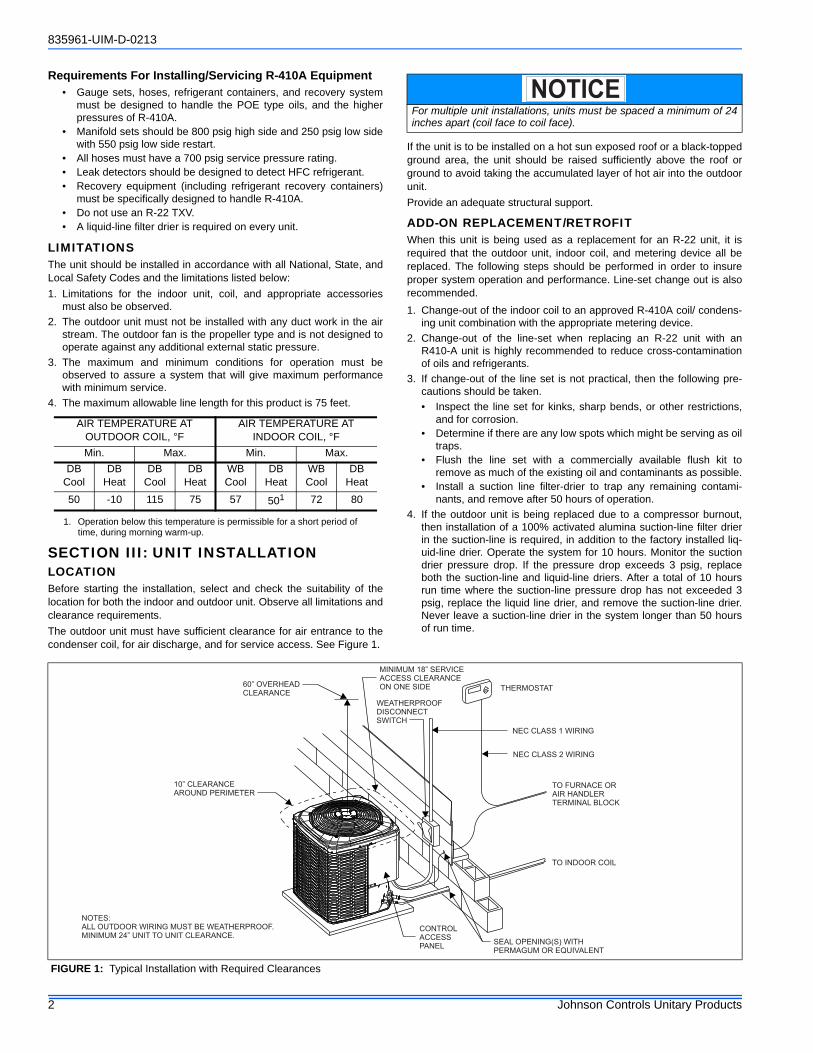
The outdoor unit must have sufficient clearance for air entrance to thecondenser coil, for air discharge, and for service access. See Figure 1.
If the unit is to be installed on a hot sun exposed roof or a black-toppedground area, the unit should be raised sufficiently above the roof orground to avoid taking the accumulated layer of hot air into the outdoorunit.
Provide an adequate structural support.
ADD-ON REPLACEMENT/RETROFITWhen this unit is being used as a replacement for an R-22 unit, it isrequired that the outdoor unit, indoor coil, and metering device all bereplaced. The following steps should be performed in order to insureproper system operation and performance. Line-set change out is alsorecommended.
1. Change-out of the indoor coil to an approved R-410A coil/ condens-ing unit combination with the appropriate metering device.
2. Change-out of the line-set when replacing an R-22 unit with anR410-A unit is highly recommended to reduce cross-contaminationof oils and refrigerants.
3. If change-out of the line set is not practical, then the following pre-cautions should be taken.
• Inspect the line set for kinks, sharp bends, or other restrictions,and for corrosion.
• Determine if there are any low spots which might be serving as oiltraps.
• Flush the line set with a commercially available flush kit toremove as much of the existing oil and contaminants as possible.
• Install a suction line filter-drier to trap any remaining contami-nants, and remove after 50 hours of operation.
4. If the outdoor unit is being replaced due to a compressor burnout,then installation of a 100% activated alumina suction-line filter drierin the suction-line is required, in addition to the factory installed liq-uid-line drier. Operate the system for 10 hours. Monitor the suctiondrier pressure drop. If the pressure drop exceeds 3 psig, replaceboth the suction-line and liquid-line driers. After a total of 10 hoursrun time where the suction-line pressure drop has not exceeded 3psig, replace the liquid line drier, and remove the suction-line drier.Never leave a suction-line drier in the system longer than 50 hoursof run time.
AIR TEMPERATURE AT OUTDOOR COIL, °F
AIR TEMPERATURE AT INDOOR COIL, °F
Min. Max. Min. Max.
DBCool
DB Heat
DBCool
DB Heat
WB Cool
DB Heat
WB Cool
DB Heat
50 -10 115 75 57 501
1. Operation below this temperature is permissible for a short period of time, during morning warm-up.
72 80
For multiple unit installations, units must be spaced a minimum of 24inches apart (coil face to coil face).
NOTICE
FIGURE 1: Typical Installation with Required Clearances
60” OVERHEAD
CLEARANCE
MINIMUM 18” SERVICE
ACCESS CLEARANCE
ON ONE SIDE
WEATHERPROOF
DISCONNECT
SWITCH
THERMOSTAT
10” CLEARANCE
AROUND PERIMETER
CONTROL
ACCESS
PANEL
TO INDOOR COIL
NEC CLASS 1 WIRING
NEC CLASS 2 WIRING
TO FURNACE OR
AIR HANDLER
TERMINAL BLOCK
SEAL OPENING(S) WITH
PERMAGUM OR EQUIVALENT
NOTES:
ALL OUTDOOR WIRING MUST BE WEATHERPROOF.
MINIMUM 24” UNIT TO UNIT CLEARANCE.
835961-UIM-D-0213
Johnson Controls Unitary Products 3
GROUND INSTALLATIONThe unit may be installed at ground level on a solid base that will notshift or settle, causing strain on the refrigerant lines and possible leaks.Maintain the clearances shown in Figure 1 and install the unit in a levelposition.
Normal operating sound levels may be objectionable if the unit is placeddirectly under windows of certain rooms (bedrooms, study, etc.).
Condensate will drain from beneath the coil of the outdoor unit duringthe defrost cycle. Normally this condensate may be allowed to draindirectly on the ground.
Elevate the unit sufficiently to prevent any blockage of the air entrancesby snow in areas where there will be snow accumulation. Check thelocal weather bureau for the expected snow accumulation in your area.
Isolate the unit from rain gutters to avoid any possible wash out of thefoundation.
ROOF INSTALLATIONWhen installing units on a roof, the structure must be capable of sup-porting the total weight of the unit, including a pad, lintels, rails, etc.,which should be used to minimize the transmission of sound or vibra-tion into the conditioned space.
UNIT PLACEMENT1. Provide a base in the pre-determined location.
2. Remove the shipping carton and inspect for possible damage.
3. Compressor tie-down bolts should remain tightened.
4. Position the unit on the base provided.
LIQUID LINE FILTER-DRIERThe heat pumps have a solid core bi-flow filter/drier located on the liquidline.
*As listed on the “Energy Guide yellow sticker on the unit.
PIPING CONNECTIONSThe outdoor unit must be connected to the indoor coil using field sup-plied refrigerant grade copper tubing that is internally clean and dry.Units should be installed only with the tubing sizes for approved systemcombinations as specified in Tabular Data Sheet. The charge given isapplicable for total tubing lengths up to 15 feet. See Application DataPart Number 247077 for installing tubing of longer lengths and elevationdifferences.
PRECAUTIONS DURING LINE INSTALLATION1. Install the lines with as few bends as possible. Care must be taken
not to damage the couplings or kink the tubing. Use clean harddrawn copper tubing where no appreciable amount of bendingaround obstruction is necessary. If soft copper must be used, caremust be taken to avoid sharp bends which may cause a restriction.
2. The lines should be installed so that they will not obstruct serviceaccess to the coil, air handling system, or filter.
3. Care must also be taken to isolate the refrigerant lines to minimizenoise transmission from the equipment to the structure.
4. The vapor line must be insulated with a minimum of 1/2" foam rubberinsulation (Armaflex or equivalent). Liquid lines that will be exposedto direct sunlight and/or high temperatures must also be insulated.
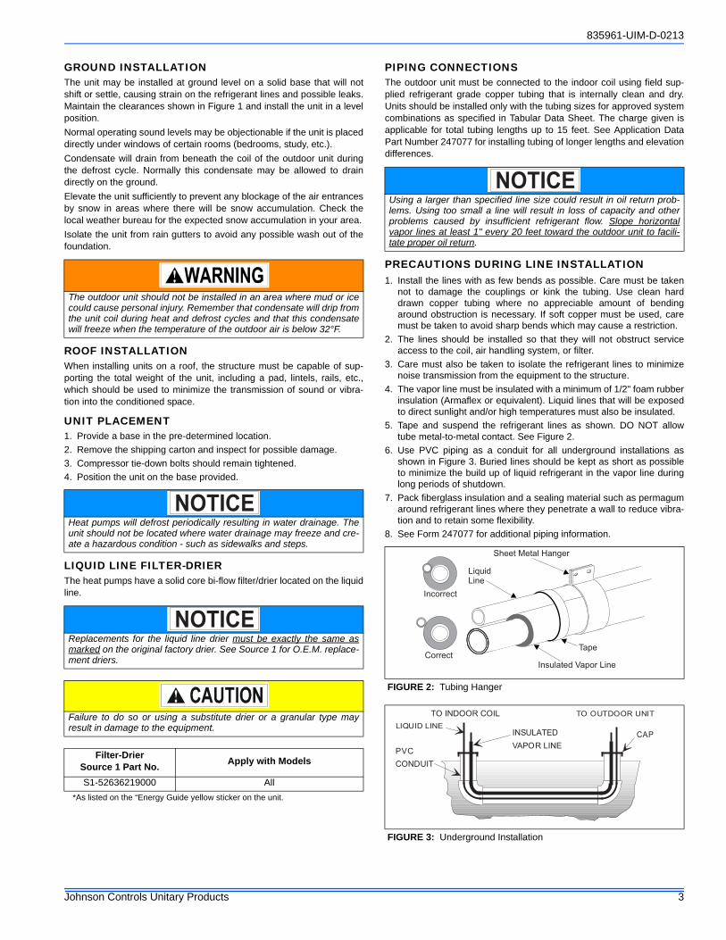
5. Tape and suspend the refrigerant lines as shown. DO NOT allowtube metal-to-metal contact. See Figure 2.
6. Use PVC piping as a conduit for all underground installations asshown in Figure 3. Buried lines should be kept as short as possibleto minimize the build up of liquid refrigerant in the vapor line duringlong periods of shutdown.
7. Pack fiberglass insulation and a sealing material such as permagumaround refrigerant lines where they penetrate a wall to reduce vibra-tion and to retain some flexibility.
8. See Form 247077 for additional piping information.
The outdoor unit should not be installed in an area where mud or icecould cause personal injury. Remember that condensate will drip fromthe unit coil during heat and defrost cycles and that this condensatewill freeze when the temperature of the outdoor air is below 32°F.
Heat pumps will defrost periodically resulting in water drainage. Theunit should not be located where water drainage may freeze and cre-ate a hazardous condition - such as sidewalks and steps.
Replacements for the liquid line drier must be exactly the same asmarked on the original factory drier. See Source 1 for O.E.M. replace-ment driers.
Failure to do so or using a substitute drier or a granular type mayresult in damage to the equipment.
Filter-DrierSource 1 Part No.
Apply with Models
S1-52636219000 All
NOTICE
NOTICE
Using a larger than specified line size could result in oil return prob-lems. Using too small a line will result in loss of capacity and otherproblems caused by insufficient refrigerant flow. Slope horizontalvapor lines at least 1" every 20 feet toward the outdoor unit to facili-tate proper oil return.
FIGURE 2: Tubing Hanger
FIGURE 3: Underground Installation
NOTICE
LiquidLine
Incorrect
CorrectTape
Sheet Metal Hanger
Insulated Vapor Line
TO INDOOR COIL TO OUTDOOR UNIT
LIQUID LINE
CAP
PVC
CONDUIT
INSULATED
VAPOR LINE
835961-UIM-D-0213
4 Johnson Controls Unitary Products
PRECAUTIONS DURING BRAZING OF LINESAll outdoor unit and evaporator coil connections are copper-to-copperand should be brazed with a phosphorous-copper alloy material suchas Silfos-5 or equivalent. DO NOT use soft solder. The outdoor unitshave reusable service valves on both the liquid and vapor connections.The total system refrigerant charge is retained within the outdoor unitduring shipping and installation. The reusable service valves are pro-vided to evacuate and charge per this instruction.
Serious service problems can be avoided by taking adequate precau-tions to assure an internally clean and dry system.
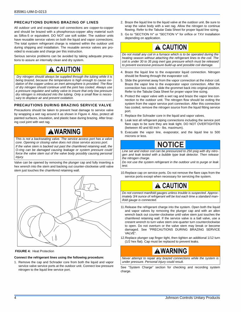
PRECAUTIONS DURING BRAZING SERVICE VALVEPrecautions should be taken to prevent heat damage to service valveby wrapping a wet rag around it as shown in Figure 4. Also, protect allpainted surfaces, insulation, and plastic base during brazing. After braz-ing cool joint with wet rag.
Valve can be opened by removing the plunger cap and fully inserting ahex wrench into the stem and backing out counter-clockwise until valvestem just touches the chamfered retaining wall.
Connect the refrigerant lines using the following procedure:
1. Remove the cap and Schrader core from both the liquid and vaporservice valve service ports at the outdoor unit. Connect low pressurenitrogen to the liquid line service port.
2. Braze the liquid line to the liquid valve at the outdoor unit. Be sure towrap the valve body with a wet rag. Allow the nitrogen to continueflowing. Refer to the Tabular Data Sheet for proper liquid line sizing.
3. Go to “SECTION IV” or “SECTION V” for orifice or TXV Installationdepending on application.
4. Braze the liquid line to the evaporator liquid connection. Nitrogenshould be flowing through the evaporator coil.
5. Slide the grommet away from the vapor connection at the indoor coil.Braze the vapor line to the evaporator vapor connection. After theconnection has cooled, slide the grommet back into original position.Refer to the Tabular Data Sheet for proper vapor line sizing.
6. Protect the vapor valve with a wet rag and braze the vapor line con-nection to the outdoor unit. The nitrogen flow should be exiting thesystem from the vapor service port connection. After this connectionhas cooled, remove the nitrogen source from the liquid fitting serviceport.
7. Replace the Schrader core in the liquid and vapor valves.
8. Leak test all refrigerant piping connections including the service portflare caps to be sure they are leak tight. DO NOT OVERTIGHTEN(between 40 and 60 inch - lbs. maximum).
9. Evacuate the vapor line, evaporator, and the liquid line to 500microns or less.
10.Replace cap on service ports. Do not remove the flare caps from theservice ports except when necessary for servicing the system.
11.Release the refrigerant charge into the system. Open both the liquidand vapor valves by removing the plunger cap and with an allenwrench back out counter-clockwise until valve stem just touches thechamfered retaining wall. If the service valve is a ball valve, use acresent wrench to turn valve stem one-quarter turn counterclockwiseto open. Do not overturn or the valve stem may break or becomedamaged. See “PRECAUTIONS DURING BRAZING SERVICEVALVE”.
12.Replace plunger cap finger tight, then tighten an additional 1/12 turn(1/2 hex flat). Cap must be replaced to prevent leaks.
See "System Charge” section for checking and recording systemcharge.
Dry nitrogen should always be supplied through the tubing while it isbeing brazed, because the temperature is high enough to cause oxi-dation of the copper unless an inert atmosphere is provided. The flowof dry nitrogen should continue until the joint has cooled. Always usea pressure regulator and safety valve to insure that only low pressuredry nitrogen is introduced into the tubing. Only a small flow is neces-sary to displace air and prevent oxidation.
This is not a backseating valve. The service access port has a valvecore. Opening or closing valve does not close service access port.If the valve stem is backed out past the chamfered retaining wall, theO-ring can be damaged causing leakage or system pressure couldforce the valve stem out of the valve body possibly causing personalinjury.
FIGURE 4: Heat Protection
Do not install any coil in a furnace which is to be operated during theheating season without attaching the refrigerant lines to the coil. Thecoil is under 30 to 35 psig inert gas pressure which must be releasedto prevent excessive pressure build-up and possible coil damage.
Line set and indoor coil can be pressurized to 250 psig with dry nitro-gen and leak tested with a bubble type leak detector. Then releasethe nitrogen charge.Do not use the system refrigerant in the outdoor unit to purge or leaktest.
Do not connect manifold gauges unless trouble is suspected. Approx-imately 3/4 ounce of refrigerant will be lost each time a standard man-ifold gauge is connected.
Never attempt to repair any brazed connections while the system isunder pressure. Personal injury could result.
NOTICE
835961-UIM-D-0213
Johnson Controls Unitary Products 5
SECTION IV: ORIFICE INSTALLATION
Install Schrader Valve Core and Orifice as follows:1. Relieve the holding charge by depressing the Schrader valve stem
located in the end of the liquid line. Cut the spundown copper toallow installation of the suction line.
2. Slide indoor coil out of cabinet far enough to gain access to equal-izer fitting on the suction line.
3. After holding charge is completely discharged remove black plasticcap on equalizer fitting.
4. Install Schrader Valve Core supplied with the outdoor unit into equal-izer fitting using a valve core tool.
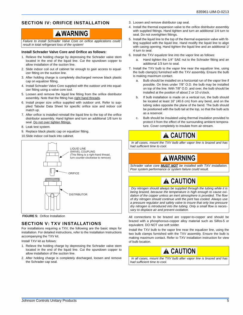
5. Loosen and remove the liquid line fitting from the orifice distributorassembly. Note that the fitting has right hand threads.
6. Install proper size orifice supplied with outdoor unit. Refer to sup-plied Tabular Data Sheet for specific orifice size and indoor coilmatch up.
7. After orifice is installed reinstall the liquid line to the top of the orificedistributor assembly. Hand tighten and turn an additional 1/8 turn toseal. Do not over tighten fittings.
8. Leak test system.
9. Replace black plastic cap on equalizer fitting.
10.Slide indoor coil back into cabinet.
SECTION V: TXV INSTALLATIONSFor installations requiring a TXV, the following are the basic steps forinstallation. For detailed instructions, refer to the Installation Instructionsaccompanying the TXV kit.
Install TXV kit as follows:
1. Relieve the holding charge by depressing the Schrader valve stemlocated in the end of the liquid line. Cut the spundown copper toallow installation of the suction line.
2. After holding charge is completely discharged, loosen and removethe Schrader cap seal.
3. Loosen and remove distributor cap seal.
4. Install the thermal expansion valve to the orifice distributor assemblywith supplied fittings. Hand tighten and turn an additional 1/4 turn toseal. Do not overtighten fittings.
5. Install the liquid line to the top of the thermal expansion valve with fit-ting supplied with the liquid line. Hand modify the liquid line to alignwith casing opening. Hand tighten the liquid line and an additional 1/4 turn to seal.
6. Install the TXV equalizer line into the vapor line as follows:
a. Hand tighten the 1/4” SAE nut to the Schrader fitting and anadditional 1/3 turn to seal.
7. Install the TXV bulb to the vapor line near the equalizer line, usingthe bulb clamp(s) furnished with the TXV assembly. Ensure the bulbis making maximum contact.
a. Bulb should be installed on a horizontal run of the vapor line ifpossible. On lines under 7/8" O.D. the bulb may be installedon top of the line. With 7/8" O.D. and over, the bulb should beinstalled at the position of about 2 or 10 o'clock.
b. If bulb installation is made on a vertical run, the bulb shouldbe located at least 16” (40.6 cm) from any bend, and on thetubing sides opposite the plane of the bend. The bulb shouldbe positioned with the bulb tail at the top, so that the bulb actsas a reservoir.
c. Bulb should be insulated using thermal insulation provided toprotect it from the effect of the surrounding ambient tempera-ture. Cover completely to insulate from air-stream.
All connections to be brazed are copper-to-copper and should bebrazed with a phosphorous-copper alloy material such as Silfos-5 orequivalent. DO NOT use soft solder.
Install the TXV bulb to the vapor line near the equalizer line, using thetwo bulb clamps furnished with the TXV assembly. Ensure the bulb ismaking maximum contact. Refer to TXV installation instruction for viewof bulb location.
Failure to install Schrader Valve Core on orifice applications couldresult in total refrigerant loss of the system!
FIGURE 5: Orifice Installation
LIQUID LINESWIVEL COUPLING(This fitting is a right-hand thread,turn counter-clockwise to remove)
ORIFICE
DISTRIBUTOR
In all cases, mount the TXV bulb after vapor line is brazed and hashad sufficient time to cool.
Schrader valve core MUST NOT be installed with TXV installation.Poor system performance or system failure could result.
Dry nitrogen should always be supplied through the tubing while it isbeing brazed, because the temperature is high enough to cause oxi-dation of the copper unless an inert atmosphere is provided. The flowof dry nitrogen should continue until the joint has cooled. Always usea pressure regulator and safety valve to insure that only low pressuredry nitrogen is introduced into the tubing. Only a small flow is neces-sary to displace air and prevent oxidation.
In all cases, mount the TXV bulb after vapor line is brazed and hashad sufficient time to cool.
835961-UIM-D-0213
6 Johnson Controls Unitary Products
SECTION VI: EVACUATIONIt will be necessary to evacuate the system to 500 microns or less. If aleak is suspected, leak test with dry nitrogen to locate the leak. Repairthe leak and test again.
To verify that the system has no leaks, simply close the valve to the vac-uum pump suction to isolate the pump and hold the system under vac-uum. Watch the micron gauge for a few minutes. If the micron gaugeindicates a steady and continuous rise, it’s an indication of a leak. If thegauge shows a rise, then levels off after a few minutes and remainsfairly constant, its an indication that the system is leak free but still con-tains moisture and may require further evacuation if the reading isabove 500 microns.
SECTION VII: SYSTEM CHARGETo ensure that your unit performs at the published levels, it is importantthat the indoor airflow is determined and refrigerant charge addedaccordingly.
Measure Indoor Air Flow:To determine rated air flow for a specific match, consult the technical lit-erature at www.upgnet.com.
Examples:
GHGD18S41S2 + AHE18B3XH21 = 610 CFM
THGF24S41S1+ FC35B3XN1 = 800 CFM
THJR36S41S4 + AHV36C3XH21 = 940 CFM
YHJD48S44S3 + FC60C3XN1H + TM9X100C20MP11A = 1625 CFM.
THGF60S41S1 + MC62D3XH1 + MV20DN21C = 1855 CFM(High) & 1160 (Low)
When attempting to match this air flow, select the lowest possible speedtap and measure the actual flow and adjust as necessary. Checkingjumper pin setting tables is not an acceptable method for determiningair flow. To determine indoor air flow, first measure the static pressurewith a manometer between the filter and blower. On a single-piece airhandler, take a second reading after the coil. On a furnace or modularair handler, take the second reading after the heat exchanger, butbefore the indoor coil. Add the negative return static to the positive sup-ply static to determine the system total static pressure. Treat the nega-tive return static as a positive pressure as even though it is a negativereading, it is static pressure on the blower; i.e. -.10 return static addedto a .40 supply static equals a .50 total system static pressure. Comparethis value the indoor unit's static pressure chart vs. CFM table or curve.
Charging the Unit:The factory charge in the outdoor unit includes enough charge for theunit, a 15 ft. (4.6 m) line set, and the smallest indoor coil/air handlermatch-up. Some indoor coil/air handler matches may require additionalcharge. See Tabular Data Sheet provided in unit Customer Booklet forcharge requirements.
The "TOTAL SYSTEM CHARGE" must be permanently marked on theunit data plate.
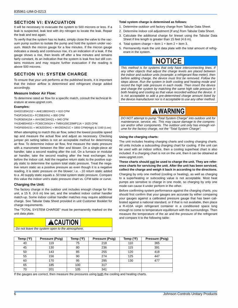
Total system charge is determined as follows:
1. Determine outdoor unit factory charge from Tabular Data Sheet.
2. Determine indoor coil adjustment (if any) from Tabular Data Sheet.
3. Calculate the additional charge for lineset using the Tabular DataSheet if line length is greater than 15 feet (4.6 m).
4. Total system charge = item 1 + item 2 + item 3.
5. Permanently mark the unit data plate with the total amount of refrig-erant in the system.
Using the charging charts:
The unit includes heating charging charts and cooling charging charts.All units include a subcooling charging chart for cooling. If the unit canbe used with an indoor orifice, then a cooling superheat chart is alsoincluded. If a charging chart is not on the unit, then it can be obtained atwww.upgnet.com.
These charts should not be used to charge the unit. They are refer-ence charts for servicing the unit. After the unit has been serviced,collect the charge and weigh it back in according to the directions.
Charging by only one method (cooling or heating), as well as chargingto a superheating or subcooling value is not acceptable. Most heatpumps are sensitive to charge in one mode, so charging by only onemode can cause it under perform in the other.
Before confirming system performance against the charging charts, youshould first confirm that your gauges are accurate by either comparingyour gauges against a calibrated pressure gauge that has been cali-brated against a national standard, or if that is not available, then placea R-410A virgin refrigerant container in a conditioned space longenough to come to temperature equilibrium with the surroundings. Thenmeasure the temperature of the air and the pressure of the refrigerantand compare it to the following table:
If the gauges are correct, then measure the pressures using both the cooling and heating charts.
Do not leave the system open to the atmosphere.
This method is for systems that only have interconnecting lines. Ifany other objects that adjust the charge levels are placed betweenthe indoor and outdoor units (example: a refrigerant flow meter), thenbefore adding charge, the device must first be removed. Follow thesteps above. Run the system in both cooling and heating mode andrecord the high side pressure in each mode. Then insert the deviceand charge the system by matching the same high side pressure inboth heating and cooling as that value recorded without the device. Itis not acceptable to add a pre-determined charge amount listed bythe device manufacturer nor is it acceptable to use any other method.
DO NOT attempt to pump “Total System Charge” into outdoor unit formaintenance, service, etc. This may cause damage to the compres-sor and/or other components. The outdoor unit only has enough vol-ume for the factory charge, not the “Total System Charge”.
NOTICE
Temp (°F) Pressure (Psig) Temp (°F) Pressure (Psig) Temp (°F) Pressure (Psig)
40 119 75 218 110 365
45 130 80 236 115 391
50 143 85 255 120 418
55 156 90 274 125 447
60 170 95 295 130 477
65 185 100 317
70 201 105 341

835961-UIM-D-0213
Johnson Controls Unitary Products 7
SECTION VIII: ELECTRICAL CONNECTIONSGENERAL INFORMATION & GROUNDINGCheck the electrical supply to be sure that it meets the values specifiedon the unit nameplate and wiring label.
Power wiring, control (low voltage) wiring, disconnect switches and overcurrent protection must be supplied by the installer. Wire size should besized per NEC requirements.
The complete connection diagram and schematic wiring label is locatedon the inside surface of the unit service access panel.
FIELD CONNECTIONS POWER WIRING1. Install the proper size weatherproof disconnect switch outdoors and
within sight of the unit.
2. Remove the screws from the control box cover and remove fromunit.
3. Run power wiring from the disconnect switch to the unit.
4. Route wires from disconnect through power wiring opening providedand into the unit control box as shown in Figures 6 or 7.
5. Install the proper size time-delay fuses or circuit breaker, and makethe power supply connections.
FIELD CONNECTIONS CONTROL WIRING1. Route low voltage wiring into bottom of control box as shown in Fig-
ures 6 or 7. Make low voltage wiring connections inside the low volt-age box per Figures 8-9.
2. The complete connection diagram and schematic wiring label islocated on the inside surface of the unit service access panel.
3. Replace the control box cover removed in Step 2.
4. All field wiring to be in accordance with national electrical codes(NEC) and/or local-city codes.
5. Mount the thermostat about 5 ft. above the floor, where it will beexposed to normal room air circulation. Do not place it on an outsidewall or where it is exposed to the radiant effect from exposed glassor appliances, drafts from outside doors or supply air grilles.
6. Route the 24-volt control wiring (NEC Class 2) from the outdoor unitto the indoor unit and thermostat.
Refrigerant charging should only be carried out by a qualified air con-ditioning contractor.
Compressor damage will occur if system is improperly charged. Onnew system installations, charge system per tabular data sheet forthe matched coil and follow guidelines in this instruction.
IT IS UNLAWFUL TO KNOWINGLY VENT, RELEASE OR DIS-CHARGE REFRIGERANT INTO THE OPEN AIR DURING REPAIR,SERVICE, MAINTENANCE OR THE FINAL DISPOSAL OF THISUNIT.
All field wiring must USE COPPER CONDUCTORS ONLY and be inaccordance with Local, National, Fire, Safety & Electrical Codes. Thisunit must be grounded with a separate ground wire in accordancewith the above codes.
FIGURE 6: Outdoor Unit Control Box - Single Phase FIGURE 7: Outdoor Unit Control Box - Three Phase
Start
Relay
(Optional)
Defrost
Control
Board
Start Capacitor
(Optional)Ground
Lug
“Fingered”
Bushing
Low
Voltage
Box
Reversible High
Voltage Conduit Plate
Contactor
Dual
Run/Fan
Capacitor
FanRelay
DefrostControlBoard
GroundLug
“Fingered”Bushing
LowVoltageBox
Reversible HighVoltage Conduit Plate
Contactor
FanCapacitor
To eliminate erratic operation, seal the hole in the wall at the thermo-stat with permagum or equivalent to prevent air drafts affecting theoperation of in the thermostat.A Start Assist Kit is available and recommended for long line setapplications or in areas of known low voltage problems.
NOTICE
835961-UIM-D-0213
8 Johnson Controls Unitary Products
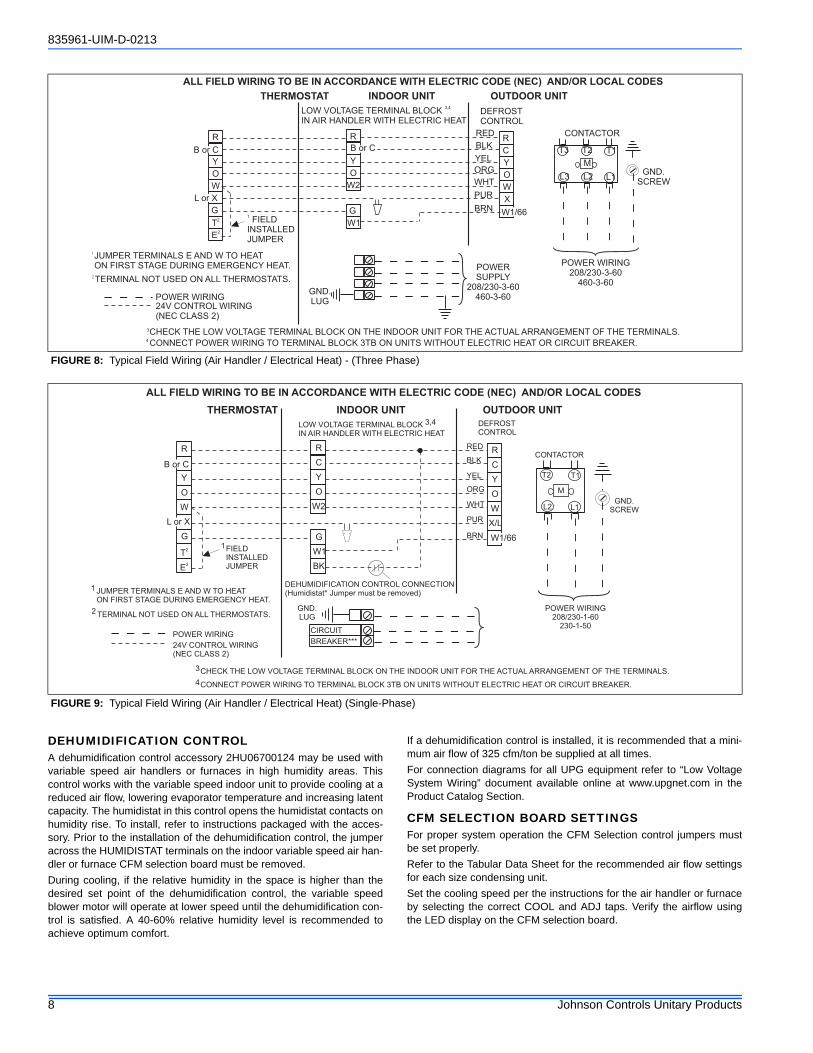
DEHUMIDIFICATION CONTROLA dehumidification control accessory 2HU06700124 may be used withvariable speed air handlers or furnaces in high humidity areas. Thiscontrol works with the variable speed indoor unit to provide cooling at areduced air flow, lowering evaporator temperature and increasing latentcapacity. The humidistat in this control opens the humidistat contacts onhumidity rise. To install, refer to instructions packaged with the acces-sory. Prior to the installation of the dehumidification control, the jumperacross the HUMIDISTAT terminals on the indoor variable speed air han-dler or furnace CFM selection board must be removed.
During cooling, if the relative humidity in the space is higher than thedesired set point of the dehumidification control, the variable speedblower motor will operate at lower speed until the dehumidification con-trol is satisfied. A 40-60% relative humidity level is recommended toachieve optimum comfort.
If a dehumidification control is installed, it is recommended that a mini-mum air flow of 325 cfm/ton be supplied at all times.
For connection diagrams for all UPG equipment refer to “Low VoltageSystem Wiring” document available online at www.upgnet.com in theProduct Catalog Section.
CFM SELECTION BOARD SETTINGSFor proper system operation the CFM Selection control jumpers mustbe set properly.
Refer to the Tabular Data Sheet for the recommended air flow settingsfor each size condensing unit.
Set the cooling speed per the instructions for the air handler or furnaceby selecting the correct COOL and ADJ taps. Verify the airflow usingthe LED display on the CFM selection board.
FIGURE 8: Typical Field Wiring (Air Handler / Electrical Heat) - (Three Phase)
FIGURE 9: Typical Field Wiring (Air Handler / Electrical Heat) (Single-Phase)
THERMOSTAT INDOOR UNIT OUTDOOR UNIT
LOW VOLTAGE TERMINAL BLOCK
IN AIR HANDLER WITH ELECTRIC HEAT
3,4
DEFROST
CONTROL
1
FIELD
INSTALLED
JUMPER
GND.
SCREW
CONTACTOR
T2 T1
L2 L1
M
R
Y
O
W
G
T2
E2
R R
Y Y
OO
W2 W
C
X
G
W1
GND.
LUGPOWER WIRING
24V CONTROL WIRING
(NEC CLASS 2)
JUMPER TERMINALS E AND W TO HEAT
ON FIRST STAGE DURING EMERGENCY HEAT.
1
2TERMINAL NOT USED ON ALL THERMOSTATS.
POWER WIRING
208/230-3-60
460-3-60
3CHECK THE LOW VOLTAGE TERMINAL BLOCK ON THE INDOOR UNIT FOR THE ACTUAL ARRANGEMENT OF THE TERMINALS.4CONNECT POWER WIRING TO TERMINAL BLOCK 3TB ON UNITS WITHOUT ELECTRIC HEAT OR CIRCUIT BREAKER.
ALL FIELD WIRING TO BE IN ACCORDANCE WITH ELECTRIC CODE (NEC) AND/OR LOCAL CODES
RED
BLK
YEL
ORG
BRN
PUR
WHT
POWER
SUPPLY
208/230-3-60
460-3-60
T3
L3
W1/66
B or C
L or X
B or C
THERMOSTAT INDOOR UNIT OUTDOOR UNIT
LOW VOLTAGE TERMINAL BLOCK
IN AIR HANDLER WITH ELECTRIC HEAT
DEFROST
CONTROL
FIELD
INSTALLED
JUMPER
DEHUMIDIFICATION CONTROL CONNECTION
(Humidistat* Jumper must be removed)
GND.
SCREW
CONTACTOR
T2 T1
L2 L1
M
R
L or X
Y
O
W
G
T2
E2
R R
Y Y
OO
W2 W
C C
X/L
G
W1
BK
GND.
LUG
CIRCUIT
BREAKER***POWER WIRING
24V CONTROL WIRING
(NEC CLASS 2)
JUMPER TERMINALS E AND W TO HEAT
ON FIRST STAGE DURING EMERGENCY HEAT.
TERMINAL NOT USED ON ALL THERMOSTATS.POWER WIRING
208/230-1-60
230-1-50
CHECK THE LOW VOLTAGE TERMINAL BLOCK ON THE INDOOR UNIT FOR THE ACTUAL ARRANGEMENT OF THE TERMINALS.
CONNECT POWER WIRING TO TERMINAL BLOCK 3TB ON UNITS WITHOUT ELECTRIC HEAT OR CIRCUIT BREAKER.
B or C
ALL FIELD WIRING TO BE IN ACCORDANCE WITH ELECTRIC CODE (NEC) AND/OR LOCAL CODES
RED
BLK
YEL
ORG
WHT
PUR
BRN
1
2
3
4
1
3,4
W1/66
835961-UIM-D-0213
Johnson Controls Unitary Products 9
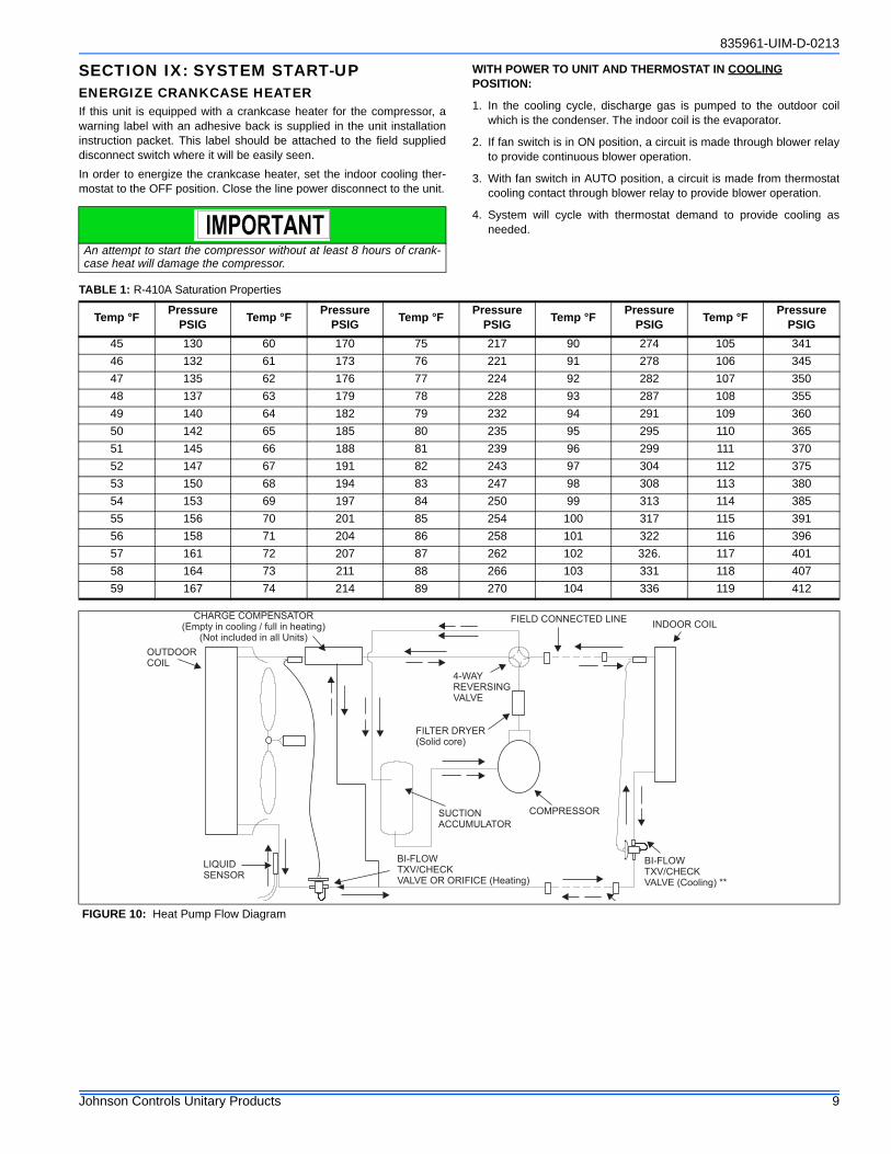
SECTION IX: SYSTEM START-UPENERGIZE CRANKCASE HEATERIf this unit is equipped with a crankcase heater for the compressor, awarning label with an adhesive back is supplied in the unit installationinstruction packet. This label should be attached to the field supplieddisconnect switch where it will be easily seen.
In order to energize the crankcase heater, set the indoor cooling ther-mostat to the OFF position. Close the line power disconnect to the unit.
WITH POWER TO UNIT AND THERMOSTAT IN COOLING POSITION:
1. In the cooling cycle, discharge gas is pumped to the outdoor coilwhich is the condenser. The indoor coil is the evaporator.
2. If fan switch is in ON position, a circuit is made through blower relayto provide continuous blower operation.
3. With fan switch in AUTO position, a circuit is made from thermostatcooling contact through blower relay to provide blower operation.
4. System will cycle with thermostat demand to provide cooling asneeded.
An attempt to start the compressor without at least 8 hours of crank-case heat will damage the compressor.
TABLE 1: R-410A Saturation Properties
Temp °FPressure
PSIGTemp °F
Pressure PSIG
Temp °FPressure
PSIGTemp °F
Pressure PSIG
Temp °FPressure
PSIG
45 130 60 170 75 217 90 274 105 341
46 132 61 173 76 221 91 278 106 345
47 135 62 176 77 224 92 282 107 350
48 137 63 179 78 228 93 287 108 355
49 140 64 182 79 232 94 291 109 360
50 142 65 185 80 235 95 295 110 365
51 145 66 188 81 239 96 299 111 370
52 147 67 191 82 243 97 304 112 375
53 150 68 194 83 247 98 308 113 380
54 153 69 197 84 250 99 313 114 385
55 156 70 201 85 254 100 317 115 391
56 158 71 204 86 258 101 322 116 396
57 161 72 207 87 262 102 326. 117 401
58 164 73 211 88 266 103 331 118 407
59 167 74 214 89 270 104 336 119 412
FIGURE 10: Heat Pump Flow Diagram
CHARGE COMPENSATOR(Empty in cooling / full in heating)
(Not included in all Units)
FIELD CONNECTED LINEINDOOR COIL
OUTDOORCOIL
4-WAYREVERSINGVALVE
FILTER DRYER(Solid core)
SUCTIONACCUMULATOR
LIQUIDSENSOR
COMPRESSOR
BI-FLOWTXV/CHECKVALVE (Cooling) **
BI-FLOWTXV/CHECKVALVE OR ORIFICE (Heating)
835961-UIM-D-0213
10 Johnson Controls Unitary Products
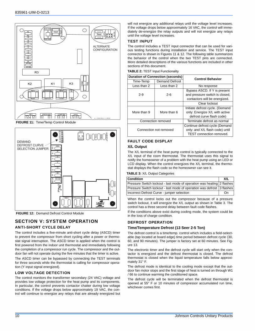
SECTION V: SYSTEM OPERATIONANTI-SHORT CYCLE DELAYThe control includes a five-minute anti-short cycle delay (ASCD) timerto prevent the compressor from short cycling after a power or thermo-stat signal interruption. The ASCD timer is applied when the control isfirst powered from the indoor unit thermostat and immediately followingthe completion of a compressor run cycle. The compressor and the out-door fan will not operate during the five minutes that the timer is active.
The ASCD timer can be bypassed by connecting the TEST terminalsfor three seconds while the thermostat is calling for compressor opera-tion (Y input signal energized).
LOW VOLTAGE DETECTIONThe control monitors the transformer secondary (24 VAC) voltage andprovides low voltage protection for the heat pump and its components.In particular, the control prevents contactor chatter during low voltageconditions. If the voltage drops below approximately 19 VAC, the con-trol will continue to energize any relays that are already energized but
will not energize any additional relays until the voltage level increases.If the voltage drops below approximately 16 VAC, the control will imme-diately de-energize the relay outputs and will not energize any relaysuntil the voltage level increases.
TEST INPUTThe control includes a TEST input connector that can be used for vari-ous testing functions during installation and service. The TEST inputconnector is shown in Figures 11 & 12. The following table summarizesthe behavior of the control when the two TEST pins are connected.More detailed descriptions of the various functions are included in othersections of this document.
FAULT CODE DISPLAYX/L OutputThe X/L terminal of the heat pump control is typically connected to theX/L input of the room thermostat. The thermostat uses this signal tonotify the homeowner of a problem with the heat pump using an LED orLCD display. When the control energizes the X/L terminal, the thermo-stat displays the flash code so the homeowner can see it.
When the control locks out the compressor because of a pressureswitch lockout, it will energize the X/L output as shown in Table 3. Thecontrol has a three second delay between fault code flashes.
If the conditions above exist during cooling mode, the system could bein the loss of charge condition.
DEFROST OPERATIONTime/Temperature Defrost (13 Seer 2-5 Ton)The defrost control is a time/temp. control which includes a field-select-able (tap located at board edge) time period between defrost cycle (30,60, and 90 minutes). The jumper is factory set at 60 minutes. See Fig-ure 13.
The electronic timer and the defrost cycle will start only when the con-tactor is energized and the defrost thermostat is closed. The defrostthermostat is closed when the liquid temperature falls below approxi-mately 31° F.
The defrost mode is identical to the cooling mode except that the out-door fan motor stops and the first stage of heat is turned on through W1/ 66 to continue warming the conditioned space.
The defrost cycle will be terminated when the defrost thermostat isopened at 55° F or 10 minutes of compressor accumulated run time,whichever comes first.
FIGURE 11: Time/Temp Control Module
FIGURE 12: Demand Defrost Control Module
90
30
60
Test
RU
NT
IME
MIN
.S
EL
REV
PRESSURE COMP RLY DFST
VALVE
OM
XL
XL
R
R
C
C
Y
Y
O
O
W
WW1/66
W1/66
PRESSURE
SWITCH
DFST
T’STAT M
M
K2 K1 K3
R3
RUN TIME
30
90
TEST
TE
ST
RUN TIME
REV
CO
ND
.
FA
N
ALTERNATE
CONFIGURATION
ALTERNATE
TEST AM
BIE
NT
AM
BG
CO
ILG
CO
IL
1234
CO
ND
FA
N
HIG
HV
OLTA
GE
PRESSURE
MSWITCH
REV
VALVE
X/L
R
C
Y
O
W
W1/66
X/L
RC
YO
WW
1/6
6
DEMANDDEFROST CURVESELECTION JUMPER
P
TABLE 2: TEST Input Functionality
Duration of Connection (seconds)Control Behavior
Time-Temp Demand DefrostLess than 2 Less than 2 No response
2-9 2-6Bypass ASCD. If Y is present and pressure switch is closed, contactors will be energized.
Clear lockout
More than 9 More than 6Initiate defrost cycle. (Demand only: Energize X/L with active
defrost curve flash code)Connection removed Terminate defrost as normal
Connection not removedContinue defrost cycle (Demand
only: and X/L flash code) until TEST connection removed.
TABLE 3: X/L Output Categories
Condition X/LPressure Switch lockout - last mode of operation was heating 2 flashesPressure Switch lockout - last mode of operation was defrost 3 flashesIncorrect Defrost Curve - jumper selection On
835961-UIM-D-0213
Johnson Controls Unitary Products 11
Demand Defrost (13 Seer 1.5 ton, 14.5 Seer 1.5-4 Ton)The control maintains proper airflow through the outdoor coil duringheating operation by melting frost and ice that may form on the coil.Frost may accumulate unevenly in different sections of the coil becauseof the arrangement of the refrigeration circuit within the coil. The controlmay initiate a defrost cycle even when the coil is not completely cov-ered with frost. This is normal operation.
The control regulates the defrost operation of the heat pump based onaccumulated compressor run time, outdoor coil temperature, and out-door ambient temperature. The control will cause the unit to operate inthe normal heating mode until it determines that a defrost cycle isneeded.
All defrost timings are based on accumulated compressor run time.
OperationThe defrost mode is equivalent to the cooling mode except that the out-door fan motor is de-energized. The control shall do the following to ini-tiate a defrost cycle.
• De-energize the outdoor fan.• Energize the reversing valve.• Energize the auxiliary heat output through the W1/66 terminal.• Begin the maximum defrost cycle length timer.
If the call for heating (Y) is removed from the control during the defrostcycle, it will terminate the defrost cycle and de-energize the compres-sor. The control will also stop the defrost cycle length timer but not resetit. When the control receives another call for heating, it will restart thedefrost cycle and the timer at the point at which the call for heating wasremoved. This will happen only if the liquid line temperature conditionsallow defrost to occur.
Defrost CurvesThe control uses a set of defrost curve parameters that are selectedusing the defrost curve selection jumper. The location of the defrostcurve selection jumper is shown in Figure 13. Table 4 shows the jumperposition that is appropriate for each heat pump model. Jumper position4 is not used and the control will not allow the compressor to operatewhen the jumper is in this position.
Defrost Curve SelectionThe factory will place the defrost curve selection jumper in the P posi-tion or in a numbered position appropriate for the specific heat pumpmodel. You should not have to change the defrost curve selectionjumper during initial installation.
If the jumper is inadvertently moved, it should be placed in the appropri-ate numbered location based on the model number and Table 4. Thecontrol will also not energize the compressor if the defrost curve selec-tion jumper is in a numbered position that is not described in Table 4 orif the defrost curve selection jumper is missing. The control will displaythe proper fault code when a defrost curve jumper error is present. Thecontrol will display the active defrost curve using the X/L terminal whenthe heat pump is operating in a defrost cycle that has been forced usingthe TEST inputs.
For instance, the X/L output will be energized with two flashes whendefrost curve 2 is active. The control only reads the jumper input whenthe Y and W thermostat inputs are de-energized. If a jumper position ischanged while either of these inputs is energized, the control will not actupon the jumper changes until the thermostat calls are de-energized orpower (24 VAC) to the control is cycled.
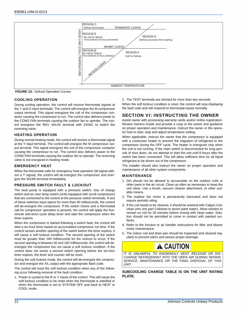
Defrost Cycle InitiationThe control will allow the heat pump to operate in the heating mode untilthe combination of outdoor ambient and outdoor coil temperatures indi-cate that a defrost cycle is necessary.
The control will initiate a defrost cycle when the liquid line temperatureis below the initiate point for the measured ambient temperature (SeeFigure 13) continuously for 4-1/2 minutes. This delay eliminates unnec-essary defrost cycles caused by refrigeration surges such as those thatoccur at the start of a heating cycle.
The control will initiate a defrost cycle every 6 hours (accumulated com-pressor run time) to recirculate refrigerant lubricants. This forceddefrost timer will be reset and restarted following the completion or ter-mination of a defrost cycle.
The control will also initiate a defrost cycle when the TEST terminalsare shorted. This feature allows an installer or service technician to starta defrost cycle immediately as required. When the TEST terminals areshorted for more than six seconds with a Y input energized and thepressure switch input is closed, the ASCD will be bypassed and thecompressor and the W1/66 terminal to auxiliary heat will be energized.
When the TEST inputs are used to force a defrost cycle, the control willignore the state of the liquid line temperature and outdoor ambient tem-perature inputs. The coil does not have to be cold and the outdoor tem-perature does not have to be within a certain range for the heat pump tobe forced into a defrost cycle. After the TEST input jumper is removed,the defrost mode will be terminated as normal. The defrost cycle lengthtimer will not be started until the TEST input is removed. If the TEST ter-minals remain shorted, the control will keep the unit in defrost mode.
Defrost InhibitionThe control will not initiate a defrost cycle if the liquid line temperature isabove 40°F unless the defrost cycle is forced using the TEST input.
The control will also prevent a defrost cycle from being initiated toosoon after the initiation of the previous defrost cycle. When power isapplied to the control and after the completion or termination of eachdefrost cycle, the control will start a 40-minute timer. When this timerexpires, the control will allow another defrost cycle when needed. Thetimer is based on accumulated compressor run time.
Defrost TerminationThe control will terminate the defrost cycle immediately after the liquidline temperature reaches 80°F or after eight minutes of defrost opera-tion.
The control will do the following to terminate a defrost cycle:
• Energize the outdoor fan.• De-energize the reversing valve.• De-energize the auxiliary heat output through the W1/66 terminal.• Reset and restart the 40-minute defrost inhibit timer.
Compressor DelayWhen Defrost Jumper Position #2 is selected the compressor is shutdown for 30 seconds entering and exiting defrost mode. This delay ispresent in normal operation but is not present when the TEST pins areshorted to force a defrost cycle. Position #1 is recommended for recip-rocating compressors, and Position #2 is recommended for scroll com-pressors.
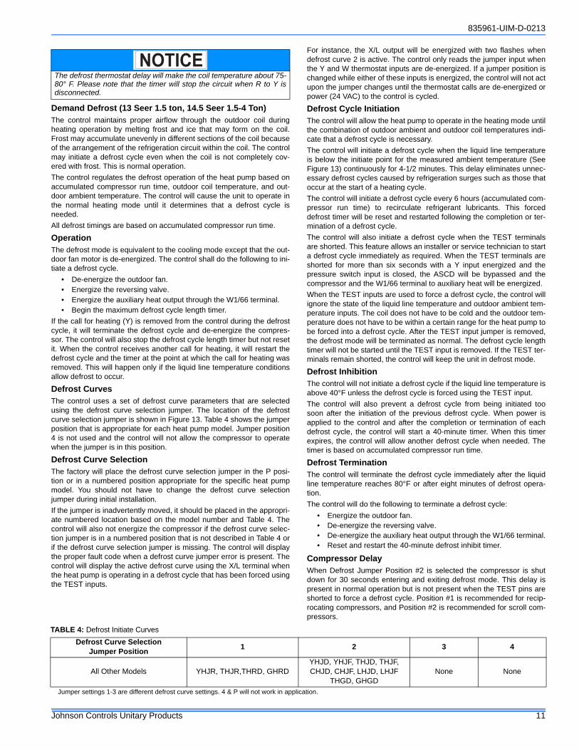
Jumper settings 1-3 are different defrost curve settings. 4 & P will not work in application.
The defrost thermostat delay will make the coil temperature about 75-80° F. Please note that the timer will stop the circuit when R to Y isdisconnected.
NOTICE
TABLE 4: Defrost Initiate Curves
Defrost Curve Selection Jumper Position
1 2 3 4
All Other Models YHJR, THJR,THRD, GHRDYHJD, YHJF, THJD, THJF,CHJD, CHJF, LHJD, LHJF
THGD, GHGDNone None
835961-UIM-D-0213
12 Johnson Controls Unitary Products
COOLING OPERATIONDuring cooling operation, the control will receive thermostat signals atthe Y and O input terminals. The control will energize the M compressoroutput terminal. This signal energizes the coil of the compressor con-tactor causing the compressor to run. The control also delivers power tothe COND FAN terminals causing the outdoor fan to operate. The con-trol energizes the REV VALVE terminal with 24VAC to switch thereversing valve.
HEATING OPERATIONDuring normal heating mode, the control will receive a thermostat signalat the Y input terminal. The control will energize the M compressor out-put terminal. This signal energizes the coil of the compressor contactorcausing the compressor to run. The control also delivers power to theCOND FAN terminals causing the outdoor fan to operate. The reversingvalve is not energized in heating mode.
EMERGENCY HEATWhen the thermostat calls for emergency heat operation (W signal with-out a Y signal), the control will de-energize the compressor and ener-gize the W1/66 terminal immediately.
PRESSURE SWITCH FAULT & LOCKOUTThe heat pump is equipped with a pressure switch, loss of chargeswitch and an over temp switch (units equipped with scroll compressor)that are connected to the control at the pressure switch terminals. If oneof these switches input opens for more than 40 milliseconds, the controlwill de-energize the compressor. If the switch closes and a thermostatcall for compressor operation is present, the control will apply the five-minute anti-short cycle delay timer and start the compressor when thetimer expires.
When the compressor is started following a switch fault, the control willstart a six-hour timer based on accumulated compressor run time. If thecontrol senses another opening of the switch before the timer expires, itwill cause a soft lockout condition. The second opening of the switchmust be greater than 160 milliseconds for the lockout to occur. If thesecond opening is between 40 and 160 milliseconds, the control will de-energize the compressor but not cause a soft lockout condition. If thecontrol does not sense a second switch opening before the six-hourtimer expires, the timer and counter will be reset.
During the soft lockout mode, the control will de-energize the compres-sor and energize the X/L output with the appropriate flash code.
The control will reset the soft lockout condition when any of the follow-ing occur following removal of the fault condition.
1. Power is cycled to the R or Y inputs of the control. This will cause thesoft lockout condition to be reset when the thermostat is satisfied orwhen the thermostat is set to SYSTEM OFF and back to HEAT orCOOL mode.
2. The TEST terminals are shorted for more than two seconds.
When the soft lockout condition is reset, the control will stop displayingthe fault code and will respond to thermostat inputs normally.
SECTION VI: INSTRUCTING THE OWNERAssist owner with processing warranty cards and/or online registration.Review Owners Guide and provide a copy to the owner and guidanceon proper operation and maintenance. Instruct the owner or the opera-tor how to start, stop and adjust temperature setting.
When applicable, instruct the owner that the compressor is equippedwith a crankcase heater to prevent the migration of refrigerant to thecompressor during the OFF cycle. The heater is energized only whenthe unit is not running. If the main switch is disconnected for long peri-ods of shut down, do not attempt to start the unit until 8 hours after theswitch has been connected. This will allow sufficient time for all liquidrefrigerant to be driven out of the compressor.
The installer should also instruct the owner on proper operation andmaintenance of all other system components.
MAINTENANCE1. Dirt should not be allowed to accumulate on the outdoor coils or
other parts in the air circuit. Clean as often as necessary to keep theunit clean. Use a brush, vacuum cleaner attachment, or other suit-able means.
2. The outdoor fan motor is permanently lubricated and does notrequire periodic oiling.
3. If the coil needs to be cleaned, it should be washed with Calgon Coil-clean (mix one part Coilclean to seven parts water). Allow solution toremain on coil for 30 minutes before rinsing with clean water. Solu-tion should not be permitted to come in contact with painted sur-faces.
4. Refer to the furnace or air handler instructions for filter and blowermotor maintenance.
5. The indoor coil and drain pan should be inspected and cleaned reg-ularly to prevent odors and assure proper drainage.
SUBCOOLING CHARGE TABLE IS ON THE UNIT RATINGPLATE.
FIGURE 13: Defrost Operation Curves
REGION C
TERMINATE CURVE
INHIBIT CURVE
INIT
IATE
CURVE
REGION AREGION B
REGION D
REGION E
AMBIENT TEMPERATURE
LIQ
UID
LIN
E (C
OIL
)T
EM
PE
RA
TU
RE
Defrost prevented from starting
No call for defrost
Time Defrost (6 hour) prevented
No call for Defrost
Time Defrost (6 hour) allowed Call for Defrost
Defrost Terminated
IT IS UNLAWFUL TO KNOWINGLY VENT, RELEASE OR DIS-CHARGE REFRIGERANT INTO THE OPEN AIR DURING REPAIR,SERVICE, MAINTENANCE OR THE FINAL DISPOSAL OF THISUNIT.
835961-UIM-D-0213
Johnson Controls Unitary Products 13
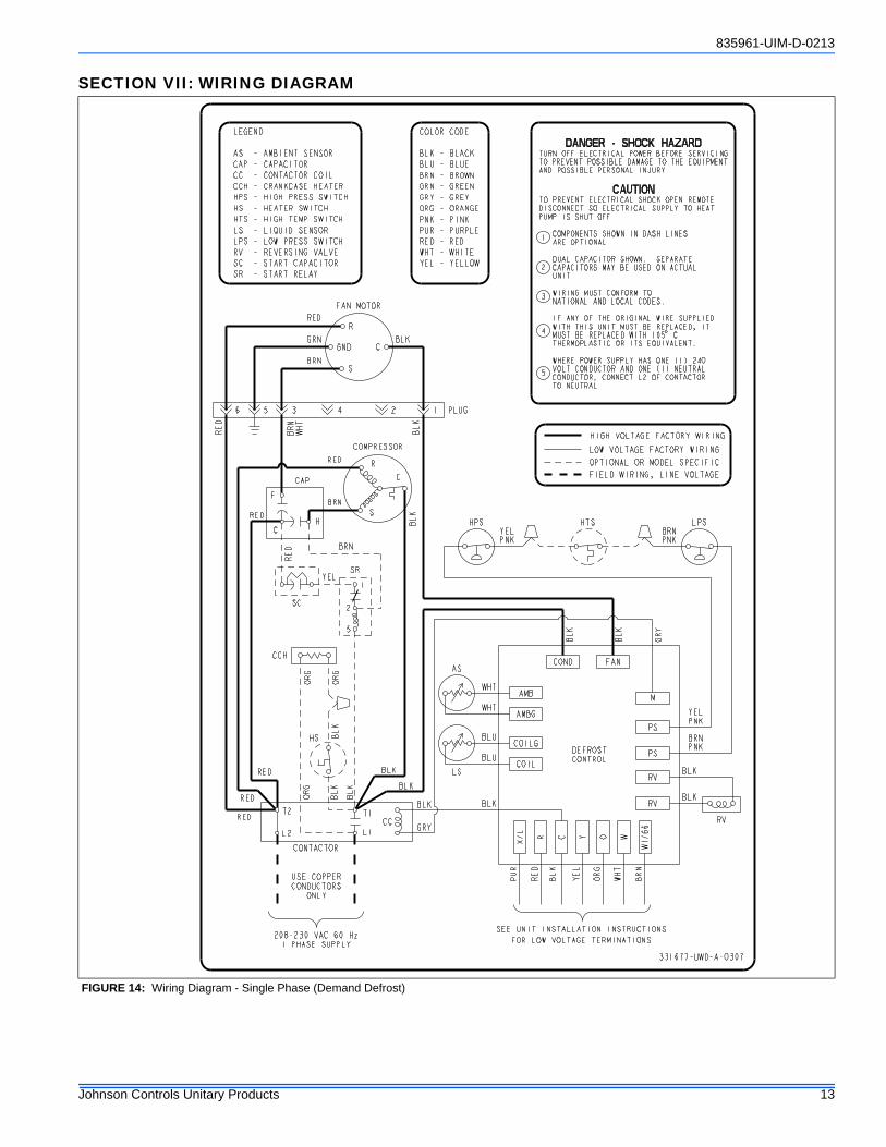
SECTION VII: WIRING DIAGRAM
FIGURE 14: Wiring Diagram - Single Phase (Demand Defrost)
835961-UIM-D-0213
14 Johnson Controls Unitary Products
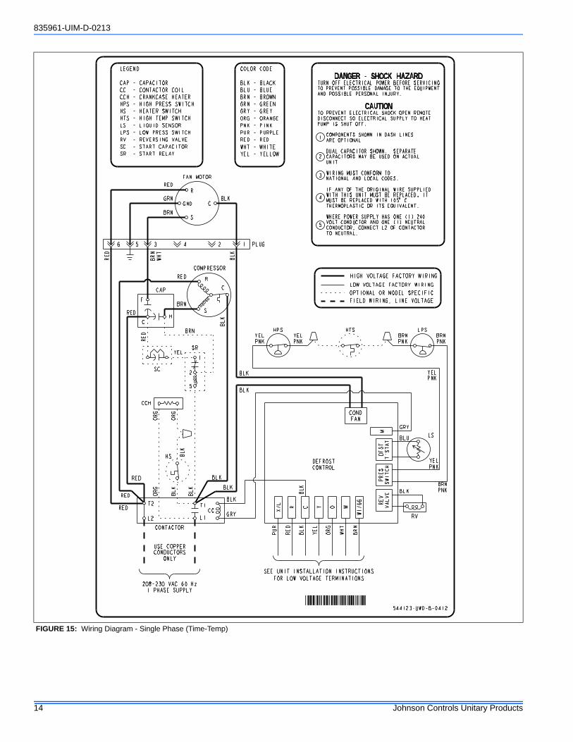
FIGURE 15: Wiring Diagram - Single Phase (Time-Temp)
544123-UWD-B-0412
S
C
R
FAN MOTOR
GND
6 35 4 2 1
GRN
BRN
RED
BLK
BRN
WHT
S
C
R
BRN
CAP
HC
F
RED
L1L2
T1T2
USE COPPERCONDUCTORS
ONLY
208-230 VAC 60 Hz1 PHASE SUPPLY
CC
CCH
COMPRESSOR
PLUG
CONTACTOR
RED
RED
RED BLK
BLK
RED
RED
BLK
BLK
BLK
RED
ORG
BLK
ORG
BLK
YEL1
2
5
SC
SR
HS
GRY
BLK
ORG
FIELD WIRING, LINE VOLTAGE
OPTIONAL OR MODEL SPECIFIC
LOW VOLTAGE FACTORY WIRING
HIGH VOLTAGE FACTORY WIRING
LEGEND
CAP - CAPACITORCC - CONTACTOR COILCCH - CRANKCASE HEATERHPS - HIGH PRESS SWITCHHS - HEATER SWITCHHTS - HIGH TEMP SWITCHLS - LIQUID SENSORLPS - LOW PRESS SWITCHRV - REVERSING VALVESC - START CAPACITORSR - START RELAY
COLOR CODE
BLK - BLACKBLU - BLUEBRN - BROWNGRN - GREENGRY - GREYORG - ORANGEPNK - PINKPUR - PURPLERED - REDWHT - WHITEYEL - YELLOW
BLK
BLK
BRNPNK
YELPNK
HPS HTS LPSBRNPNK
YELPNK
YELPNK
SEE UNIT INSTALLATION INSTRUCTIONSFOR LOW VOLTAGE TERMINATIONS
CONDFAN
X/L
PUR
RED
DEFROSTCONTROL
BLK
WHT
BRN
BLK
REV
VALVE
YEL
ORG
RV
R C Y O W
W1/66
PRES
SWITCH
DFST
T'STAT
M
BRNPNK
YELPNK
BLK
GRY
LSBLU
DANGER - SHOCK HAZARDTURN OFF ELECTRICAL POWER BEFORE SERVICINGTO PREVENT POSSIBLE DAMAGE TO THE EQUIPMENTAND POSSIBLE PERSONAL INJURY.
CAUTIONTO PREVENT ELECTRICAL SHOCK OPEN REMOTEDISCONNECT SO ELECTRICAL SUPPLY TO HEATPUMP IS SHUT OFF.
COMPONENTS SHOWN IN DASH LINES ARE OPTIONAL.
DUAL CAPACITOR SHOWN. SEPARATE CAPACITORS MAY BE USED ON ACTUAL UNIT.
WIRING MUST CONFORM TO NATIONAL AND LOCAL CODES.
IF ANY OF THE ORIGINAL WIRE SUPPLIED WITH THIS UNIT MUST BE REPLACED, IT MUST BE REPLACED WITH 105 C THERMOPLASTIC OR ITS EQUIVALENT.
WHERE POWER SUPPLY HAS ONE (1) 240 VOLT CONDUCTOR AND ONE (1) NEUTRAL CONDUCTOR, CONNECT L2 OF CONTACTOR TO NEUTRAL.
1
2
3
4
5
BRN
��������
835961-UIM-D-0213
Johnson Controls Unitary Products 15
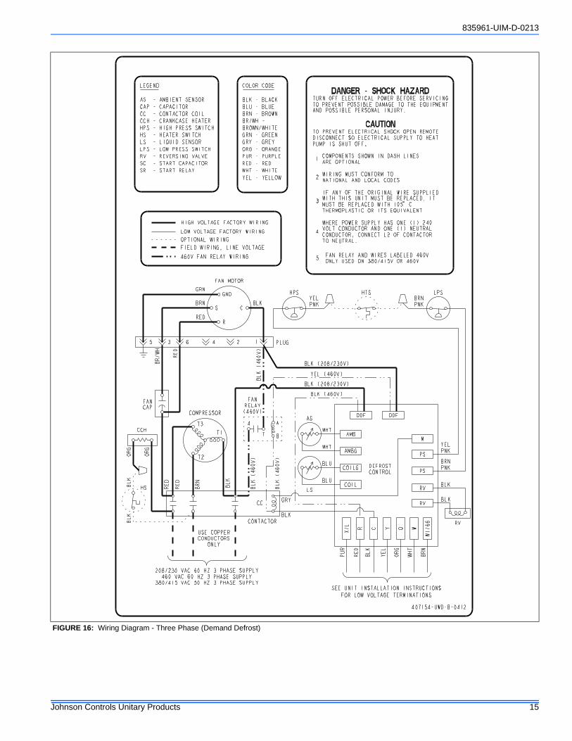
FIGURE 16: Wiring Diagram - Three Phase (Demand Defrost)
R
C
GND
FAN MOTOR
S
5 63 4 2 1
BRN
RED
GRN
BLK
USE COPPERCONDUCTORS
ONLY
208/230 VAC 60 HZ 3 PHASE SUPPLY460 VAC 60 HZ 3 PHASE SUPPLY
380/415 VAC 50 HZ 3 PHASE SUPPLY
COMPRESSOR
FIELD WIRING, LINE VOLTAGE
OPTIONAL WIRING
LOW VOLTAGE FACTORY WIRING
HIGH VOLTAGE FACTORY WIRING
PLUG
CONTACTOR
PUR
SEE UNIT INSTALLATION INSTRUCTIONSFOR LOW VOLTAGE TERMINATIONS
ODFODF
X/L
R C Y O W
W1/66
AMB
AMBG
COILG
COIL
DEFROSTCONTROL
WHT
WHT
BLU
BLU
RED
BLK
YEL
ORG
WHT
BRN
LS
AS
DANGER - SHOCK HAZARDTURN OFF ELECTRICAL POWER BEFORE SERVICINGTO PREVENT POSSIBLE DAMAGE TO THE EQUIPMENTAND POSSIBLE PERSONAL INJURY.
CAUTIONTO PREVENT ELECTRICAL SHOCK OPEN REMOTEDISCONNECT SO ELECTRICAL SUPPLY TO HEATPUMP IS SHUT OFF.
COMPONENTS SHOWN IN DASH LINES ARE OPTIONAL.
WIRING MUST CONFORM TO NATIONAL AND LOCAL CODES.
IF ANY OF THE ORIGINAL WIRE SUPPLIED WITH THIS UNIT MUST BE REPLACED, IT MUST BE REPLACED WITH 105 C THERMOPLASTIC OR ITS EQUIVALENT.
WHERE POWER SUPPLY HAS ONE (1) 240 VOLT CONDUCTOR AND ONE (1) NEUTRAL CONDUCTOR, CONNECT L2 OF CONTACTOR TO NEUTRAL.
FAN RELAY AND WIRES LABELED 460V ONLY USED ON 380/415V OR 460V
1
2
3
4
LEGEND
AS - AMBIENT SENSORCAP - CAPACITORCC - CONTACTOR COILCCH - CRANKCASE HEATERHPS - HIGH PRESS SWITCHHS - HEATER SWITCHLS - LIQUID SENSORLPS - LOW PRESS SWITCHRV - REVERSING VALVESC - START CAPACITORSR - START RELAY
COLOR CODE
BLK - BLACKBLU - BLUEBRN - BROWNBR/WH -BROWN/WHITEGRN - GREENGRY - GREYORG - ORANGEPUR - PURPLERED - REDWHT - WHITEYEL - YELLOW
407154-UWD-B-0412
460V FAN RELAY WIRING
RED
BR/WH
CCH
HS
ORG
ORG
BLK
BLK
CC
FANRELAY(460V)
FANCAP
GRY
RED
RED
BRN
BLK
BLK (460V)
BLK (460V)
BLK (460V)
BLK (208/230V)
YEL (460V)
BLK (208/230V)
BLK (460V)
BLK
5
7
4
B
A
PS
PS
M
RV
RV
BRNPNK
YELPNK
HPS HTS LPS
RV
BLK
BLK
BRNPNK
YELPNK
T2
T1
T3
835961-UIM-D-0213
16 Johnson Controls Unitary Products
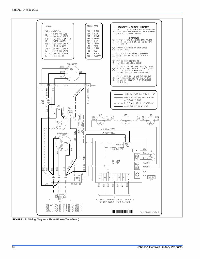
FIGURE 17: Wiring Diagram - Three Phase (Time-Temp)
545127-UWD-C-0412
R
C
GND
FAN MOTOR
S
5 63 4 2 1
BRN
RED
GRN
BLK
T2
T1
T3RED
USE COPPERCONDUCTORS
ONLY
208-230 VAC 60 Hz 3 PHASE SUPPLY460 VAC 60 Hz 3 PHASE SUPPLY575 VAC 60 Hz 3 PHASE SUPPLY380/415 VAC 60 Hz 3 PHASE SUPPLY
COMPRESSOR
PLUG
CONTACTOR
RED
RED
BLK
BLK
BLK (208/230V)
BLK (208/230)
BRN
BLK
4
B
A
FANRELAY(460V)
HS
GRY
BLK
LEGEND
CAP - CAPACITORCC - CONTACTOR COILCCH - CRANKCASE HEATERHPS - HIGH PRESS SWITCHHS - HEATER SWITCHHTS - HIGH TEMP SWITCHLS - LIQUID SENSORLPS - LOW PRESS SWITCHRV - REVERSING VALVESC - START CAPACITORSR - START RELAY
COLOR CODE
BLK - BLACKBLU - BLUEBRN - BROWNGRN - GREENGRY - GREYORG - ORANGEPNK - PINKPUR - PURPLERED - REDWHT - WHITEYEL - YELLOW
7
BRN
CC
FANCAP
C
F
RED
ORG
BLK
ORG
ORG
BLK (460V)
BLK (460V)
BLK (460V)
BLK (460V)
RED
BRN/WHT
BLK (208/230)
BLK (208/230)
BRNPNK
YELPNK
HPS HTS LPSBRNPNK
YELPNK
YEL/PNK
SEE UNIT INSTALLATION INSTRUCTIONSFOR LOW VOLTAGE TERMINATIONS
CONDFAN
X/L
PUR
RED
DEFROSTCONTROL
BLK
WHT
BRN
BLK
REV
VALVE
YEL
ORG
RV
R C Y O W
W1/66
PRESS
SWITCH
DFST
T'STAT
M
BRN/PNK
GRY
BLK
YEL (460V)
BLK (460V)LS
BLU
DANGER - SHOCK HAZARDTURN OFF ELECTRICAL POWER BEFORE SERVICINGTO PREVENT POSSIBLE DAMAGE TO THE EQUIPMENTAND POSSIBLE PERSONAL INJURY.
CAUTIONTO PREVENT ELECTRICAL SHOCK OPEN REMOTEDISCONNECT SO ELECTRICAL SUPPLY TO HEATPUMP IS SHUT OFF.
COMPONENTS SHOWN IN DASH LINES ARE OPTIONAL.
DUAL CAPACITOR SHOWN. SEPARATE CAPACITORS MAY BE USED ON ACTUAL UNIT.
WIRING MUST CONFORM TO NATIONAL AND LOCAL CODES.
IF ANY OF THE ORIGINAL WIRE SUPPLIED WITH THIS UNIT MUST BE REPLACED, IT MUST BE REPLACED WITH 105 C THERMOPLASTIC OR ITS EQUIVALENT.
WHERE POWER SUPPLY HAS ONE (1) 240 VOLT CONDUCTOR AND ONE (1) NEUTRAL CONDUCTOR, CONNECT L2 OF CONTACTOR TO NEUTRAL.
1
2
3
4
5
BLK
BLU
FIELD WIRING, LINE VOLTAGE
OPTIONAL WIRING
LOW VOLTAGE FACTORY WIRING
HIGH VOLTAGE FACTORY WIRING
460V FAN RELAY WIRINGCCH
YEL (460V)
��������

835961-UIM-D-0213
Johnson Controls Unitary Products 17
NOTES
835961-UIM-D-0213
18 Johnson Controls Unitary Products
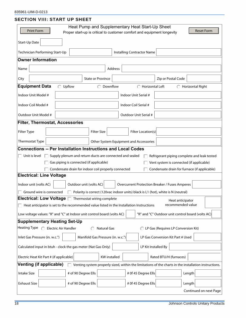
SECTION VIII: START UP SHEETHeat Pump and Supplementary Heat Start-Up Sheet
Proper start-up is critical to customer comfort and equipment longevity
Name Address
City State or Province Zip or Postal Code
Indoor Unit Model # Indoor Unit Serial #
Indoor Coil Model # Indoor Coil Serial #
Upflow Downflow Horizontal Left Horizontal Right
Unit is level
Venting system properly sized, within the limitations of the charts in the installation instructions.
Condensate drain for indoor coil properly connected
Filter Type
Intake Size
Exhaust Size
# of 90 Degree Ells # 0f 45 Degree Ells Length
Length # 0f 45 Degree Ells# of 90 Degree Ells
Polarity is correct (120vac indoor units) black is L1 (hot), white is N (neutral)Ground wire is connected
Indoor unit (volts AC)
Low voltage values: "R" and "C" at Indoor unit control board (volts AC)
Thermostat Type Other System Equipment and Accessories
Owner Information
Equipment Data
Venting (if applicable)
Electrical: Line Voltage
Outdoor Unit Model # Outdoor Unit Serial #
Filter, Thermostat, Accessories
Filter Location(s)
Connections -- Per Installation Instructions and Local Codes
Gas piping is connected (if applicable)
Supply plenum and return ducts are connected and sealed
Filter Size
Vent system is connected (if applicable)
Thermostat wiring complete
Heat anticipator is set to the recommended value listed in the Installation Instructions
Electrical: Low Voltage
Technician Performing Start-Up Installing Contractor Name
Start-Up Date
Condensate drain for furnace (if applicable)
Refrigerant piping complete and leak tested
Outdoor unit (volts AC) Overcurrent Protection Breaker / Fuses Amperes
"R" and "C" Outdoor unit control board (volts AC)
Supplementary Heating Set-Up Natural Gas LP Gas (Requires LP Conversion Kit)Electric Air Handler
LP Gas Conversion Kit Part # Used
LP Kit Installed By
Inlet Gas Pressure (in. w.c.")
Calculated input in btuh - clock the gas meter (Nat Gas Only)
Manifold Gas Pressure (in. w.c.")
Heating Type
Heat anticipator recommended value
Electric Heat Kit Part # (if applicable) KW installed
Continued on next Page
Rated BTU/H (furnaces)
Print Form Reset Form
835961-UIM-D-0213
Johnson Controls Unitary Products 19
Supply static after indoor coil (in w.c.")
Return Static (in w.c.") before filter
Total External Static Pressure
Low
1 2
Medium Low Medium
3 4
Medium High High
5
A B DC
A B C D
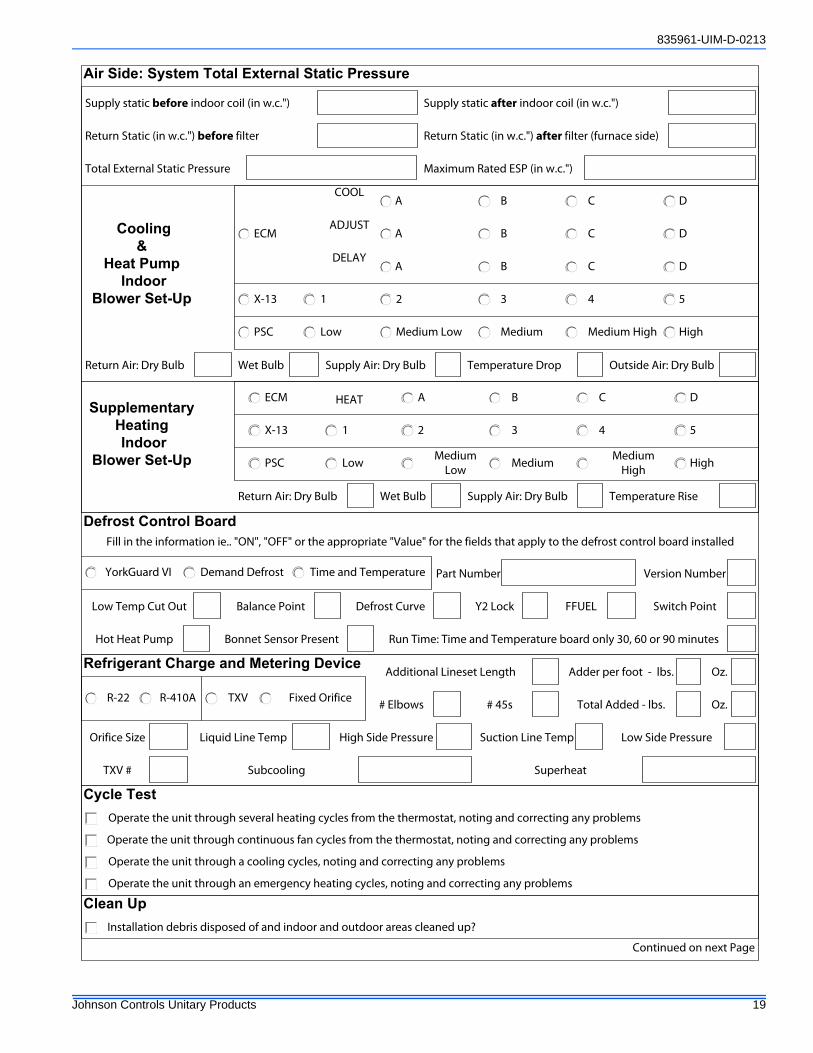
Air Side: System Total External Static Pressure
Supply static before indoor coil (in w.c.")
Return Static (in w.c.") after filter (furnace side)
Cooling &
Heat Pump Indoor
Blower Set-Up
COOL
ADJUSTECM
X-13
PSC
A B C DDELAY
Supplementary
Heating Indoor
Blower Set-Up
ECM
X-13
PSC
A
1 5
High
2 3 4
Low Medium Low Medium Medium
High
DB C
Outside Air: Dry Bulb Temperature DropSupply Air: Dry BulbReturn Air: Dry Bulb Wet Bulb
Temperature RiseReturn Air: Dry Bulb Supply Air: Dry BulbWet Bulb
Version Number
Defrost Control Board
Part NumberDemand DefrostYorkGuard VI Time and Temperature
Maximum Rated ESP (in w.c.")
Low Temp Cut Out Balance Point Defrost Curve Y2 Lock FFUEL Switch Point
Hot Heat Pump
Fill in the information ie.. "ON", "OFF" or the appropriate "Value" for the fields that apply to the defrost control board installed
Run Time: Time and Temperature board only 30, 60 or 90 minutesBonnet Sensor Present
HEAT
Refrigerant Charge and Metering Device
TXV Fixed OrificeR-22 R-410A
Oz.
# 45s# Elbows
TXV #
Orifice Size Liquid Line Temp
Subcooling Superheat
High Side Pressure Low Side PressureSuction Line Temp
Additional Lineset Length Adder per foot - lbs.
Total Added - lbs. Oz.
Cycle TestOperate the unit through several heating cycles from the thermostat, noting and correcting any problems
Operate the unit through continuous fan cycles from the thermostat, noting and correcting any problems
Operate the unit through a cooling cycles, noting and correcting any problems
Operate the unit through an emergency heating cycles, noting and correcting any problems
Installation debris disposed of and indoor and outdoor areas cleaned up?
Clean Up
Continued on next Page
Subject to change without notice. Published in U.S.A. 835961-UIM-D-0213Copyright © 2013 by Johnson Controls, Inc. All rights reserved. Supersedes: 835961-UIM-C-0712
York International Corp.5005 York Drive
Norman, OK 73069
Explain operation of system to equipment owner
Explain the importance of regular filter replacement and equipment maintenance
Owner EducationProvide owner with the owner's manual
Explain thermostat use and programming (if applicable) to owner
Comments Section