Embed Size (px)
Citation preview
L-JET/S
55 10
10
+- LSNS
210
80 10+-
++
--
+-
LS
NS 230
V ~
Sense
L-JET/S
55 10
10
+- LSNS
210
80 10+-
++
--
+-
LS
NS 230
V ~
Sense
Installationsanleitung
LED-Treiber für INOTEC LED-Module zum Anschluß an CLS 24-System und 230V-Zentralbatterieanlagen mit 24V-Einschub/24V BUS-Unterstation.Gem. EN 55015, EN 61000-3-2, EN 61347-1 und EN 61547.
L-JET 1 Artikel Nr. 860 021 L-JET 3 Artikel Nr. 860 023L-JET 2 Artikel Nr. 860 032 L-JET 7 Artikel Nr. 860 027Vorgesehen für den Einbau in Leuchten.Zur Einzelüberwachung von INOTEC LED-Leuchten.
L-JET 1/S Artikel Nr. 860 031L-JET 3/S Artikel Nr. 860 033L-JET 7/S Artikel Nr. 860 037Vorgesehen für den Einbau in Leuchten.Zur Einzelüberwachung von INOTEC LED-Leuchten mit 230V Schalteingang.
LED-Supply 24-3 SK III ext. Artikel Nr. 890 453LED-Supply 24-3 SK III ext. Artikel Nr. 890 613LED-Supply 24-7 SK III ext.Artikel Nr. 890 497Vorgesehen für den Deckeneinbau. Ausführung in Schutzklasse III.Zur Einzelüberwachung von INOTEC LED-Leuchten.
LED-Supply 24-3 S SK II ext. Artikel Nr. 890 485LED-Supply 24-7 S SK II ext. Artikel Nr. 890 486Vorgesehen für den Deckeneinbau. Ausführung in Schutzklasse II.Zur Einzelüberwachung von INOTEC LED-Leuchten mit 230V Schalteingang.
Technische Daten
L-JET L-JET/SEingangsspannung: 24V±20%DC 24V±25%DCAusgangsspannung: max. 24V max. 30V Zul. Temp. Bereich: -15 ...+50°C -15 ...+45°C
Anschlussklemmen: max. 2,5mm² eindrähtig oder max. 1,5mm² Litze mit Aderendhülse abhängig vom Klemmentyp2polige Stiftleiste für LED
Funkentstörung: gem. DIN EN 55015Schutzart: IP 20Gehäuse: Polycarbonat V0max. Drehmoment: 0,9Nm
L-JET 1 Order No. 860 021 L-JET 3 Order No. 860 023L-JET 2 Order No. 860 032 L-JET 7 Order No. 860 027Designed to be fitted inside luminaires.For individual lamp monitoring of INOTEC LED luminaires. L-JET 1/S Order No. 860 031 L-JET 7/S Order No. 860 037L-JET 3/S Order No. 860 033Designed to be fitted inside luminaires. For individual lamp monito-ring of INOTEC LED luminaires with 230V switch-/sense-inputLED-Supply 24-3 SK III ext. Order No. 890 453LED-Supply 24-3 SK III ext. Order No. 890 613LED-Supply 24-3 SK III ext. Order No. 890 497Designed for recessed ceiling installation. Protection class III.For individual lamp monitoring of INOTEC LED luminaires.LED-Supply 24-3 S SK II ext. Order No. 890 485LED-Supply 24-7 S SK II ext. Order No. 890 486Designed for recessed ceiling installation. Protection class II.For individual lamp monitoring of INOTEC LED-luminaires, with 230V switch-/sense-input.
LED-driver for INOTEC LEDs modules for connection to CLS 24 system or 230V central power supply systems with 24V module/24V bus-substation.Built to EN 55015, EN 61000-3-2, EN 61347-1, EN 61347 2-13 and EN 61547.
Installation Instruction
Hinweise
Notes
Technische Daten
Technical data
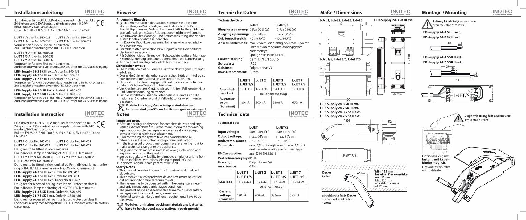
Maße / Dimensions Montage / MountingAllgemeine Hinweise
Nach dem Auspacken des Gerätes nehmen Sie bitte eine Überprüfung auf Vollständigkeit und erkennbare äußere Beschädigungen vor. Melden Sie offensichtliche Beschädigun-gen sofort, da wir spätere Reklamationen nicht anerkennen.Die Hinweise der Montage- und Betriebsanleitung sind vor der ersten Inbetriebnahme zu beachten!Im Zuge der Produktverbesserung behalten wir uns technische Änderungen vor. Bei fehlerhafter Installation bzw. Eingriff in das Gerät erlischt der Garantieanspruch! Für Schäden die auf Grund der Nichtbeachtung dieser Montage- / Betriebsanleitung entstehen, übernehmen wir keine Haftung.Generell sind nur Originalersatzteile zu verwenden!
Important notesAfter unpacking kindly check for complete delivery and any visible external damages. Furthermore, inform the forwarding agent about visible damages at once, as we do not accept complaints that reach us at a later time.Prior to starting the system take into consideration all references in the mounting and operating instructions!In the interest of product improvment we reserve the right to make technical changes to the appliance.All guarantee claims cease in case of wrong installation or of any intervention on the products. We do not take any liability for damages or injuries arising from failure to follow instructions relating to product’s useIn general original spare part must be used.
Modules, luminaires, packing materials and batteries have to be disposed as per national requirements!
SicherheitshinweiseDie Installation darf nur durch Elektrofachkräfte gem. EltbauVO erfolgen.Dieses Gerät ist ein sicherheitstechnisches Betriebsmittel, es ist entsprechend der nationalen Vorschriften zu prüfen. Das Gerät ist bestimmungsgemäß und nur in einwandfreiem, unbeschädigtem Zustand zu betreiben.Vor Arbeiten an dem Gerät ist dieses in jedem Fall von der Netz- und Batteriespannung zu trennen!Für die Installation und den Betrieb dieses Gerätes sind die nationalen Sicherheits- und Unfallverhütungsvorschriften zu beachten.
Safety NotesThis manual contains information for trained and qualified electricians.This product is a safety relevant device. Tests must be carried out according to national requirements.The system has to be operated within the design parameters and only in functional, undamaged condition.The product has to be disconnected from mains- and battery voltage prior to any work being carried out.National safety standards and legal requirements have to be observed.
Technical data
L-JET L-JET/SInput voltage: 24V±20%DC 24V±25%DCOutput voltage: max. 24V max. 30V Amb. temp. range: -15 ...+50°C -15 ...+45°C
Terminals: max. 2,5mm² single wire or max. 1,5mm² multicore depending on terminal type
EMC protection: acc. DIN EN 55015Protection category: IP 20Housing: Polycarbonat V0max. torque: 0,9Nm
L-JET 1L-JET 1/S
L-JET 2 L-JET 3L-JET 3/S
L-JET 7L-JET 7/S
LED load 1-6 LEDs 1-5 LEDs 1-4 LEDs 1-3 LEDs
series connection
Current voltage (constant)
120mA 200mA 320mA 650mA
L-JET 1L-JET 1/S
L-JET 2 L-JET 3L-JET 3/S
L-JET 7L-JET 7/S
Anschließ-bare Last
1-6 LEDs 1-5 LEDs 1-4 LEDs 1-3 LEDs
in Reihenschaltung
Ausgangs-strom (konstant)
120mA 200mA 320mA 650mA
110
mm
30 mm16 mm
90
2040
40 19
38
L-Jet 1, L-Jet 2, L-Jet 3, L-Jet 7
L-Jet 1/S, L-Jet 3/S, L-Jet 7/S
LED-Supply 24-3 SK III ext.LED-Supply 24-7 SK III ext.LED-Supply 24-3 S SK II ext.LED-Supply 24-7 S SK II ext.
LED-Supply 24-3 SK III ext.
LED-Supply 24-7 SK III ext.
LED-Supply 24-3 S SK II ext.
LED-Supply 24-7 S SK II ext.
Zugentlastung fest andrücken!Press strain relief!
Optionale Zugent-lastung mit Kabel-binder möglich.Optional strain relief with cable tie.
LED-Supply 24-3 SK III ext.
Module, Leuchten, Verpackungsmaterialien und Batterien sind gemäß den Bestimmungen zu entsorgen!
184
38 63
49
52
abgehängte feste DeckeSuspended fixed ceiling12mm
DeckeCeiling
ø68mmMin. 125 mmbei einer Deckenstärke von 12mmMin. 125 mmat a slab thickness of 12 mm
!Leitung ist wie folgt abzusetzen:
5010Strip the cable as follows:
EinstellungMode
SchalterabfrageSense inputLS / NS
Ausgang Output+ / -
Normal 0V 0V
230V ~ max. 30V
Invert 0V max. 30V
230V ~ 0V
Normal/Dim. 0V LEDs im eingestellten DimmungszustandLEDs in adjusted dimming mode
230V ~ LEDs werden gedimmt, solange Spannung anliegtLEDs will be dimmed during mains is on
Invert/Dim. 0V LEDs werden gedimmt, solange keine Spannung anliegtLEDs will be dimmed during mains is on
230V ~ LEDs im eingestellten Dimmungszustand LEDs in adjusted dimming mode
Normal/10% 0V 0V
230V ~ LEDs 10% gedimmt
Invert/10% 0V LEDs 10% gedimmt
230V ~ 0V
Normal/30% 0V 0V
230V ~ LEDs 30% gedimmt dimmed
Invert/30% 0V LEDs 30% gedimmt dimmed
230V ~ 0V
Normal/50% 0V 0V
230V ~ LEDs 50% gedimmt dimmed
Invert/50% 0V LEDs 50% gedimmt
230V ~ 0V
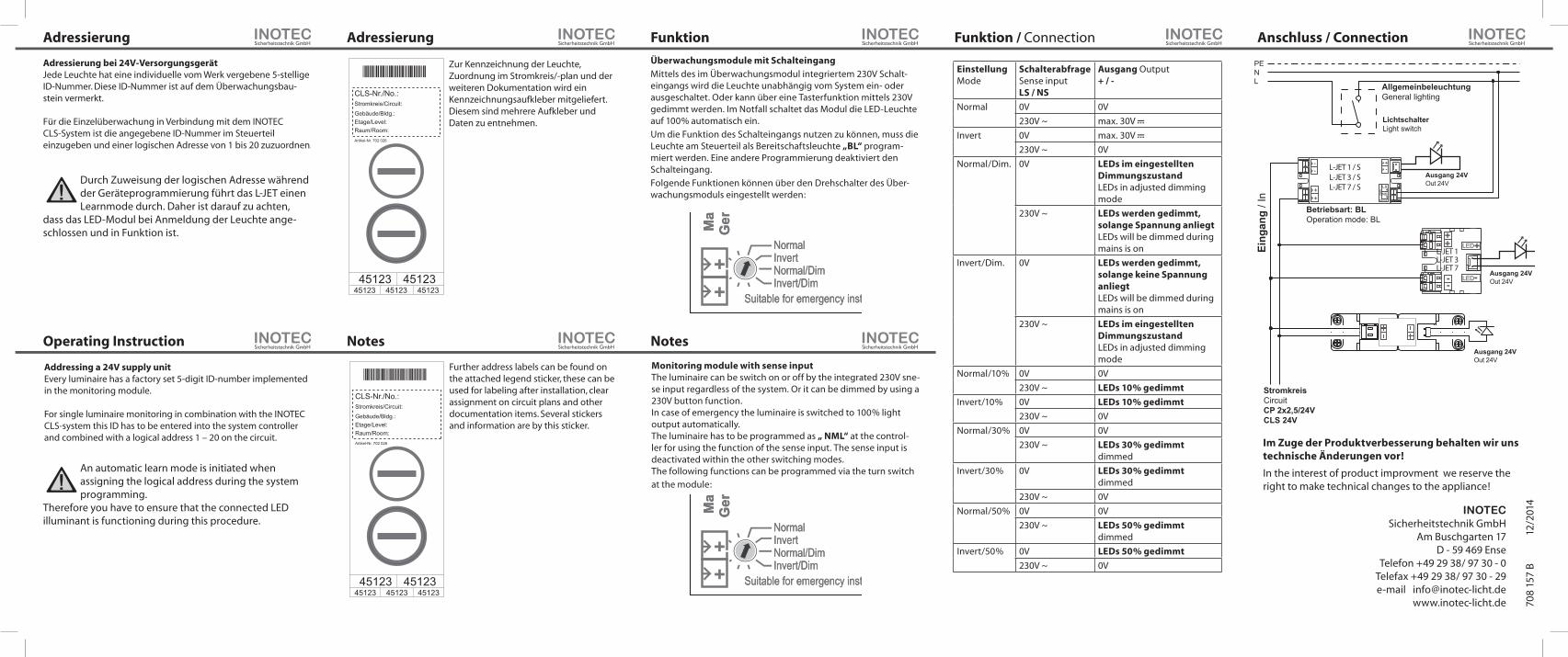
StromkreisCircuitCP 2x2,5/24VCLS 24V
Betriebsart: BLOperation mode: BL
Eing
ang
/ In
Ausgang 24VOut 24V
LichtschalterLight switch
AllgemeinbeleuchtungGeneral lighting
PENL
L-JET 1 / S L-JET 3 / S L-JET 7 / S
L-JET 1L-JET 3L-JET 7
Ausgang 24VOut 24V
Ausgang 24VOut 24V
++
--
+-
-- LED-
LED+
++
LS
NS 230
V ~
Sense
Adressierung
Operating Instruction
Adressierung
Notes
Funktion
Notes
Funktion / Connection Anschluss / Connection
Überwachungsmodule mit Schalteingang
Mittels des im Überwachungsmodul integriertem 230V Schalt-eingangs wird die Leuchte unabhängig vom System ein- oder ausgeschaltet. Oder kann über eine Tasterfunktion mittels 230V gedimmt werden. Im Notfall schaltet das Modul die LED-Leuchte auf 100% automatisch ein.
Um die Funktion des Schalteingangs nutzen zu können, muss die Leuchte am Steuerteil als Bereitschaftsleuchte „BL“ program-miert werden. Eine andere Programmierung deaktiviert den Schalteingang.
Folgende Funktionen können über den Drehschalter des Über-wachungsmoduls eingestellt werden:
Monitoring module with sense input The luminaire can be switch on or off by the integrated 230V sne-se input regardless of the system. Or it can be dimmed by using a 230V button function.In case of emergency the luminaire is switched to 100% light output automatically.The luminaire has to be programmed as „ NML“ at the control-ler for using the function of the sense input. The sense input is deactivated within the other switching modes.The following functions can be programmed via the turn switch at the module:
Im Zuge der Produktverbesserung behalten wir uns technische Änderungen vor!
Adressierung bei 24V-VersorgungsgerätJede Leuchte hat eine individuelle vom Werk vergebene 5-stellige ID-Nummer. Diese ID-Nummer ist auf dem Überwachungsbau-stein vermerkt.
Für die Einzelüberwachung in Verbindung mit dem INOTEC CLS-System ist die angegebene ID-Nummer im Steuerteil einzugeben und einer logischen Adresse von 1 bis 20 zuzuordnen.
Addressing a 24V supply unit Every luminaire has a factory set 5-digit ID-number implemented in the monitoring module.
For single luminaire monitoring in combination with the INOTEC CLS-system this ID has to be entered into the system controller and combined with a logical address 1 – 20 on the circuit.
Further address labels can be found on the attached legend sticker, these can be used for labeling after installation, clear assignment on circuit plans and other documentation items. Several stickers and information are by this sticker.
CLS-Nr./No.:Stromkreis/Circuit:
Gebäude/Bldg.:Etage/Level:Raum/Room:Artikel-Nr. 702 026
45123 4512345123 45123
45123
Zur Kennzeichnung der Leuchte, Zuordnung im Stromkreis/-plan und der weiteren Dokumentation wird ein Kennzeichnungsaufkleber mitgeliefert. Diesem sind mehrere Aufkleber und Daten zu entnehmen.
CLS-Nr./No.:Stromkreis/Circuit:
Gebäude/Bldg.:Etage/Level:Raum/Room:Artikel-Nr. 702 026
45123 4512345123 45123
45123
++
INOTEC
Suitable for emergency installation acc. to EN 50172
L-JET/S --
9mm
Mad
e in
Ger
man
y SELV
equi
vale
nt
+-
NormalInvertNormal/DimInvert/Dim
UN = DC 24V ±25%UOut = max. 30Vt a = -15°C ... +45°C
860 03 1 IOut = 120mA const. 3 IOut = 320mA const. 7 IOut = 650mA const.
LS
NS 230
V ~
SenseSuitable for emergency installation acc. to EN 50172
Mad
e in
Ger
man
y
NormalInvertNormal/DimInvert/Dim
70
8 15
7 B
12/2
014
In the interest of product improvment we reserve the right to make technical changes to the appliance!
INOTEC Sicherheitstechnik GmbH
Am Buschgarten 17D - 59 469 Ense
Telefon +49 29 38/ 97 30 - 0Telefax +49 29 38/ 97 30 - 29e-mail [email protected]
www.inotec-licht.de
Durch Zuweisung der logischen Adresse während der Geräteprogrammierung führt das L-JET einen Learnmode durch. Daher ist darauf zu achten,
dass das LED-Modul bei Anmeldung der Leuchte ange-schlossen und in Funktion ist.
An automatic learn mode is initiated when assigning the logical address during the system programming.
Therefore you have to ensure that the connected LED illuminant is functioning during this procedure.