Embed Size (px)
Citation preview
© 2015 Flyzone, a Hobbico company. FLZA3030RTF/3034RxR Mnl
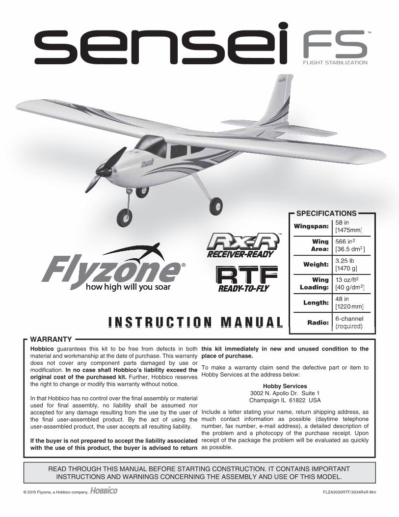
SPECIFICATIONS
Wingspan: 58 in[1475mm]
WingArea:
566 in2
[36.5 dm2]
Weight: 3.25 lb[1470 g]
WingLoading:
13 oz/ft2
[40 g/dm2]
Length: 48 in[1220mm]
Radio:6-channel(required)
READ THROUGH THIS MANUAL BEFORE STARTING CONSTRUCTION. IT CONTAINS IMPORTANTINSTRUCTIONS AND WARNINGS CONCERNING THE ASSEMBLY AND USE OF THIS MODEL.
WARRANTYHobbico guarantees this kit to be free from defects in both material and workmanship at the date of purchase. This warranty does not cover any component parts damaged by use or modification. In no case shall Hobbico’s liability exceed the original cost of the purchased kit. Further, Hobbico reserves the right to change or modify this warranty without notice.
In that Hobbico has no control over the final assembly or material used for final assembly, no liability shall be assumed nor accepted for any damage resulting from the use by the user of the final user-assembled product. By the act of using the user-assembled product, the user accepts all resulting liability.
If the buyer is not prepared to accept the liability associated with the use of this product, the buyer is advised to return
this kit immediately in new and unused condition to the place of purchase.
To make a warranty claim send the defective part or item to Hobby Services at the address below:
Hobby Services3002 N. Apollo Dr. Suite 1Champaign IL 61822 USA
Include a letter stating your name, return shipping address, as much contact information as possible (daytime telephone number, fax number, e-mail address), a detailed description of the problem and a photocopy of the purchase receipt. Upon receipt of the package the problem will be evaluated as quickly as possible.
I N S T R U C T I O N M A N U A L
®
™
™
SPECIFICATIONS
Wingspan: 58 in[1475mm]
WingArea:
566 in2
[36.5 dm2]
Weight: 3.25 lb[1470 g]
WingLoading:
13 oz/ft2
[40 g/dm2]
Length: 48 in[1220 mm]
Radio:6-channel(required)I N S T R U C T I O N M A N U A L
®
™
2
INTRODUCTIONThank you for purchasing the Flyzone Sensei. The best method to learn to fl y an R/C plane is with a stable trainer. This upgraded version of the Sensei includes a gyro stabilization system that will aid the beginning pilot in learning to fl y with an instructor and by themselves. With three modes to choose from, the amount of fl ight assistance the stabilization adds is adjustable to match your improving fl ying skills. To make it even easier, the Sensei is electric. Just charge the batteries and you’re ready fl y. When you’re done, just put the plane away until the next time. Assembly is quick and easy. In the RTF version, nothing else is needed to get you in the air.
For the latest technical updates or manual corrections to the Sensei visit the Hobbico web site at www.hobbico.com. Open the “Airplanes” link, then select “Sensei”. If there is new technical information or changes to this model a “tech notice” box will appear in the upper left corner of the page.
AMAIf you are not already a member of the AMA, please join! The AMA is the governing body of model aviation and membership provides liability insurance coverage, protects modelers’ rights and interests and is required to fl y at most R/C sites.
Academy of Model Aeronautics5151 East Memorial DriveMuncie, IN 47302-9252
Ph. (800) 435-9262Fax (765) 741-0057
Or via the Internet at: http://www.modelaircraft.org
IMPORTANT!!! Two of the most important things you can do to preserve the radio controlled aircraft hobby are to avoid fl ying near full-scale aircraft and avoid fl ying near or over groups of people.
SAFETY PRECAUTIONS
Protect Your Model, Yourself & Others…Follow These Important Safety Precautions
1. Your Sensei should not be considered a toy, but rather a sophisticated, working model that functions very much like a full-size airplane. Because of its performance capabilities, the Sensei, if not assembled and operated correctly, could possibly cause injury to yourself or spectators and damage to property.
2. You must assemble the model according to the instructions. Do not alter or modify the model, as doing so may result in an unsafe or unfl yable model. In a few cases the instructions may differ slightly from the photos. In those instances the written instructions should be considered as correct.
3. If you are not an experienced pilot or have not fl own an R/C plane before, we recommend that you get the assistance of an experienced pilot in your R/C club for your fi rst fl ights. If you’re not a member of a club, your local hobby shop has information about clubs in your area whose membership includes experienced pilots.
We, as the kit manufacturer, provide you with a top quality, thoroughly tested kit and instructions, but ultimately the quality and fl yability of your fi nished model depends on how you build it; therefore, we cannot in any way guarantee the performance of your completed model, and no representations are expressed or implied as to the performance or safety of your completed model.
INTRODUCTION . . . . . . . . . . . . . . . . . . . . . . . . . . . . . . . .2AMA . . . . . . . . . . . . . . . . . . . . . . . . . . . . . . . . . . . . . . . . . .2SAFETY PRECAUTIONS . . . . . . . . . . . . . . . . . . . . . . . . .2ADDITIONAL ITEMS REQUIRED. . . . . . . . . . . . . . . . . . .3 Radio Control System . . . . . . . . . . . . . . . . . . . . . . . . .3 Battery and Charger. . . . . . . . . . . . . . . . . . . . . . . . . . .3 Assembly Tools . . . . . . . . . . . . . . . . . . . . . . . . . . . . . .3BATTERY PREPARATIONS . . . . . . . . . . . . . . . . . . . . . . .3 Charge the Battery. . . . . . . . . . . . . . . . . . . . . . . . . . . .3 Battery Charging Precautions . . . . . . . . . . . . . . . . . . .3 Battery Recycling . . . . . . . . . . . . . . . . . . . . . . . . . . . . .3 Install the Receiver. . . . . . . . . . . . . . . . . . . . . . . . . . . .3ORDERING REPLACEMENT PARTS. . . . . . . . . . . . . . . .4ASSEMBLE THE SENSEI . . . . . . . . . . . . . . . . . . . . . . . . .5 Install the Main Landing Gear . . . . . . . . . . . . . . . . . . .5 Install the Vertical and Horizontal Stabilizer . . . . . . . . .5 Connect the Rudder and Elevator Controls . . . . . . . . .6 Install the Wing Joiner . . . . . . . . . . . . . . . . . . . . . . . . .7RX-R VERSION . . . . . . . . . . . . . . . . . . . . . . . . . . . . . . . . .8 Install the Receiver. . . . . . . . . . . . . . . . . . . . . . . . . . . .8 TTX650 Programming . . . . . . . . . . . . . . . . . . . . . . . . .8
RADIO SYSTEM . . . . . . . . . . . . . . . . . . . . . . . . . . . . . . . .9 Check the Radio System . . . . . . . . . . . . . . . . . . . . . . .9 Check the Control Throws . . . . . . . . . . . . . . . . . . . . .11 Check the Stabilization System . . . . . . . . . . . . . . . . .12 Mount the Propeller . . . . . . . . . . . . . . . . . . . . . . . . . .13 Check the C.G. (Center of Gravity) . . . . . . . . . . . . . .13 Important ESC Information . . . . . . . . . . . . . . . . . . . .14WISE GYRO STABILIZATION SYSTEM. . . . . . . . . . . . .15 Modes . . . . . . . . . . . . . . . . . . . . . . . . . . . . . . . . . . . .15 Recovery Switch . . . . . . . . . . . . . . . . . . . . . . . . . . . .15 Climb Assist . . . . . . . . . . . . . . . . . . . . . . . . . . . . . . . .16COWL REMOVAL . . . . . . . . . . . . . . . . . . . . . . . . . . . . . .16GET THE MODEL READY TO FLY. . . . . . . . . . . . . . . . .17FLYING. . . . . . . . . . . . . . . . . . . . . . . . . . . . . . . . . . . . . . .17 Takeoff . . . . . . . . . . . . . . . . . . . . . . . . . . . . . . . . . . . .18 Flight . . . . . . . . . . . . . . . . . . . . . . . . . . . . . . . . . . . . .18 Landing . . . . . . . . . . . . . . . . . . . . . . . . . . . . . . . . . . .19 Before Your Next Flight. . . . . . . . . . . . . . . . . . . . . . . .19 Improving Your Piloting Skills . . . . . . . . . . . . . . . . . . .20 Trimming . . . . . . . . . . . . . . . . . . . . . . . . . . . . . . . . . .20
TABLE OF CONTENTS
3
ADDITIONAL ITEMS REQUIRED
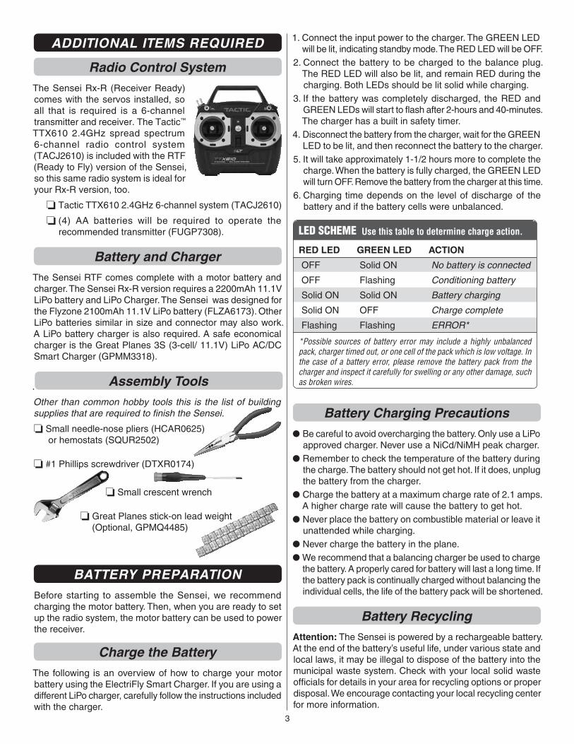
Radio Control SystemThe Sensei Rx-R (Receiver Ready) comes with the servos installed, so all that is required is a 6-channel transmitter and receiver. The Tactic™ TTX610 2.4GHz spread spectrum 6-channel radio control system (TACJ2610) is included with the RTF (Ready to Fly) version of the Sensei, so this same radio system is ideal for your Rx-R version, too.
❏ Tactic TTX610 2.4GHz 6-channel system (TACJ2610)
❏ (4) AA batteries will be required to operate the recommended transmitter (FUGP7308).
Battery and ChargerThe Sensei RTF comes complete with a motor battery and charger. The Sensei Rx-R version requires a 2200mAh 11.1V LiPo battery and LiPo Charger. The Sensei was designed for the Flyzone 2100mAh 11.1V LiPo battery (FLZA6173). Other LiPo batteries similar in size and connector may also work. A LiPo battery charger is also required. A safe economical charger is the Great Planes 3S (3-cell/ 11.1V) LiPo AC/DC Smart Charger (GPMM3318).
. Assembly ToolsOther than common hobby tools this is the list of building supplies that are required to fi nish the Sensei.
❏ Small needle-nose pliers (HCAR0625) or hemostats (SQUR2502)
❏ #1 Phillips screwdriver (DTXR0174)
❏ Small crescent wrench
❏ Great Planes stick-on lead weight(Optional, GPMQ4485)
BATTERY PREPARATIONBefore starting to assemble the Sensei, we recommend charging the motor battery. Then, when you are ready to set up the radio system, the motor battery can be used to power the receiver.
Charge the BatteryThe following is an overview of how to charge your motor battery using the ElectriFly Smart Charger. If you are using a different LiPo charger, carefully follow the instructions included with the charger.
1. Connect the input power to the charger. The GREEN LED will be lit, indicating standby mode. The RED LED will be OFF.
2. Connect the battery to be charged to the balance plug. The RED LED will also be lit, and remain RED during the charging. Both LEDs should be lit solid while charging.
3. If the battery was completely discharged, the RED and GREEN LEDs will start to fl ash after 2-hours and 40-minutes. The charger has a built in safety timer.
4. Disconnect the battery from the charger, wait for the GREEN LED to be lit, and then reconnect the battery to the charger.
5. It will take approximately 1-1/2 hours more to complete the charge. When the battery is fully charged, the GREEN LED will turn OFF. Remove the battery from the charger at this time.
6. Charging time depends on the level of discharge of the battery and if the battery cells were unbalanced.
LED SCHEME Use this table to determine charge action.
RED LED
OFF
OFF
Solid ON
Solid ON
Flashing
GREEN LED
Solid ON
Flashing
Solid ON
OFF
Flashing
ACTION
No battery is connected
Conditioning battery
Battery charging
Charge complete
ERROR*
*Possible sources of battery error may include a highly unbalanced pack, charger timed out, or one cell of the pack which is low voltage. In the case of a battery error, please remove the battery pack from the charger and inspect it carefully for swelling or any other damage, such as broken wires.
Battery Charging Precautions● Be careful to avoid overcharging the battery. Only use a LiPo
approved charger. Never use a NiCd/NiMH peak charger. ● Remember to check the temperature of the battery during
the charge. The battery should not get hot. If it does, unplug the battery from the charger.
● Charge the battery at a maximum charge rate of 2.1 amps. A higher charge rate will cause the battery to get hot.
● Never place the battery on combustible material or leave it unattended while charging.
● Never charge the battery in the plane.● We recommend that a balancing charger be used to charge
the battery. A properly cared for battery will last a long time. If the battery pack is continually charged without balancing the individual cells, the life of the battery pack will be shortened.
Battery RecyclingAttention: The Sensei is powered by a rechargeable battery. At the end of the battery’s useful life, under various state and local laws, it may be illegal to dispose of the battery into the municipal waste system. Check with your local solid waste offi cials for details in your area for recycling options or proper disposal. We encourage contacting your local recycling center for more information.
4
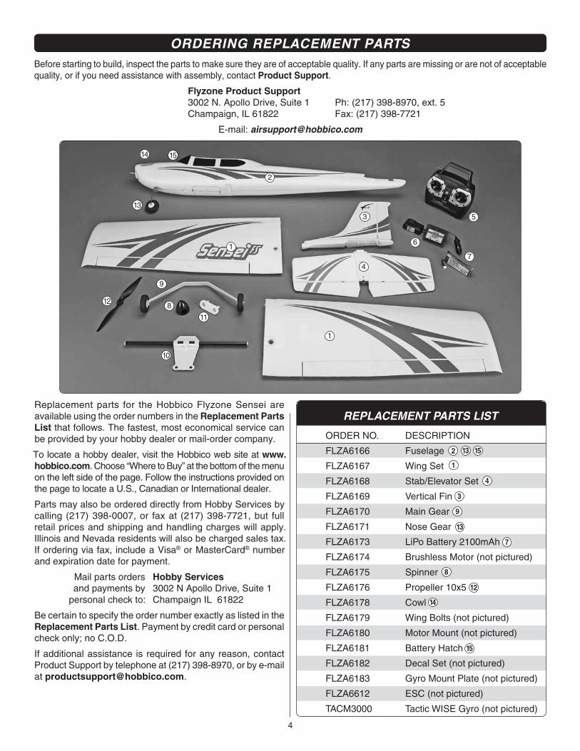
Replacement parts for the Hobbico Flyzone Sensei are available using the order numbers in the Replacement Parts List that follows. The fastest, most economical service can be provided by your hobby dealer or mail-order company.
To locate a hobby dealer, visit the Hobbico web site at www.hobbico.com. Choose “Where to Buy” at the bottom of the menu on the left side of the page. Follow the instructions provided on the page to locate a U.S., Canadian or International dealer.
Parts may also be ordered directly from Hobby Services by calling (217) 398-0007, or fax at (217) 398-7721, but full retail prices and shipping and handling charges will apply. Illinois and Nevada residents will also be charged sales tax. If ordering via fax, include a Visa® or MasterCard® number and expiration date for payment.
Mail parts orders Hobby Services and payments by 3002 N Apollo Drive, Suite 1 personal check to: Champaign IL 61822
Be certain to specify the order number exactly as listed in the Replacement Parts List. Payment by credit card or personal check only; no C.O.D.
If additional assistance is required for any reason, contact Product Support by telephone at (217) 398-8970, or by e-mail at [email protected].
REPLACEMENT PARTS LIST
ORDER NO.
FLZA6166
FLZA6167
FLZA6168
FLZA6169
FLZA6170
FLZA6171
FLZA6173
FLZA6174
FLZA6175
FLZA6176
FLZA6178
FLZA6179
FLZA6180
FLZA6181
FLZA6182
FLZA6183
FLZA6612
TACM3000
DESCRIPTION
Fuselage
Wing Set
Stab/Elevator Set
Vertical Fin
Main Gear
Nose Gear
LiPo Battery 2100mAh
Brushless Motor (not pictured)
Spinner
Propeller 10x5
Cowl
Wing Bolts (not pictured)
Motor Mount (not pictured)
Battery Hatch
Decal Set (not pictured)
Gyro Mount Plate (not pictured)
ESC (not pictured)
Tactic WISE Gyro (not pictured)
1
1
6
2
7
8
9
3 5
4
11
12
14
13
15
10
ORDERING REPLACEMENT PARTSBefore starting to build, inspect the parts to make sure they are of acceptable quality. If any parts are missing or are not of acceptable quality, or if you need assistance with assembly, contact Product Support.
Flyzone Product Support3002 N. Apollo Drive, Suite 1 Ph: (217) 398-8970, ext. 5Champaign, IL 61822 Fax: (217) 398-7721
E-mail: [email protected]
5
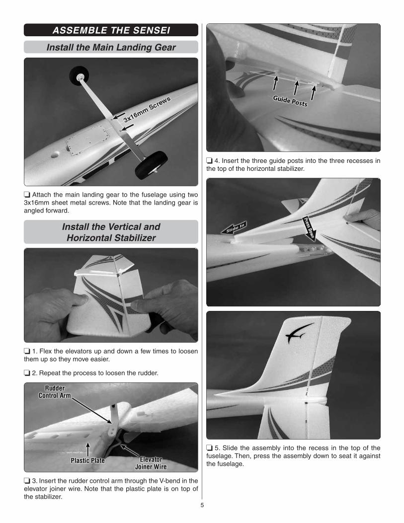
ASSEMBLE THE SENSEI
Install the Main Landing Gear
❏ Attach the main landing gear to the fuselage using two 3x16mm sheet metal screws. Note that the landing gear is angled forward.
Install the Vertical andHorizontal Stabilizer
❏ 1. Flex the elevators up and down a few times to loosen them up so they move easier.
❏ 2. Repeat the process to loosen the rudder.
❏ 3. Insert the rudder control arm through the V-bend in the elevator joiner wire. Note that the plastic plate is on top of the stabilizer.
❏ 4. Insert the three guide posts into the three recesses in the top of the horizontal stabilizer.
❏ 5. Slide the assembly into the recess in the top of the fuselage. Then, press the assembly down to seat it against the fuselage.
6
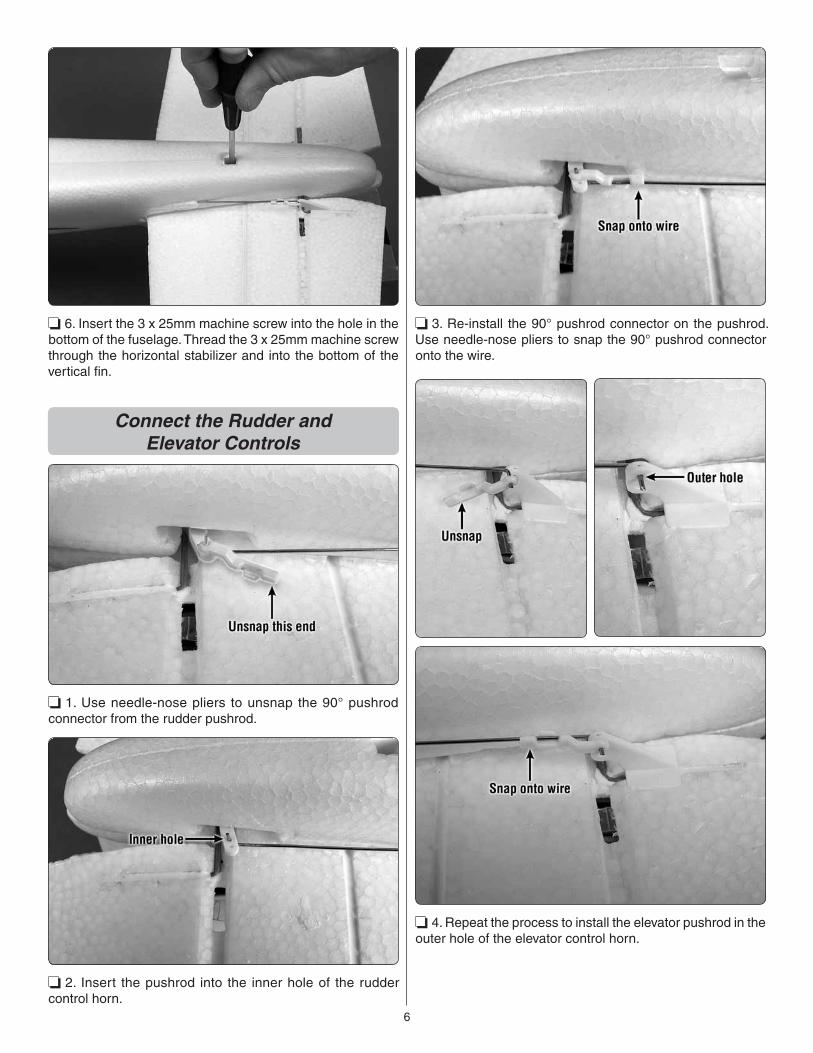
❏ 6. Insert the 3 x 25mm machine screw into the hole in the bottom of the fuselage. Thread the 3 x 25mm machine screw through the horizontal stabilizer and into the bottom of the vertical fi n.
Connect the Rudder andElevator Controls
❏ 1. Use needle-nose pliers to unsnap the 90° pushrod connector from the rudder pushrod.
❏ 2. Insert the pushrod into the inner hole of the rudder control horn.
❏ 3. Re-install the 90° pushrod connector on the pushrod. Use needle-nose pliers to snap the 90° pushrod connector onto the wire.
❏ 4. Repeat the process to install the elevator pushrod in the outer hole of the elevator control horn.
7
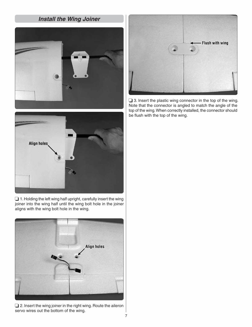
Install the Wing Joiner
❏ 1. Holding the left wing half upright, carefully insert the wing joiner into the wing half until the wing bolt hole in the joiner aligns with the wing bolt hole in the wing.
❏ 2. Insert the wing joiner in the right wing. Route the aileron servo wires out the bottom of the wing.
❏ 3. Insert the plastic wing connector in the top of the wing. Note that the connector is angled to match the angle of the top of the wing. When correctly installed, the connector should be fl ush with the top of the wing.
8
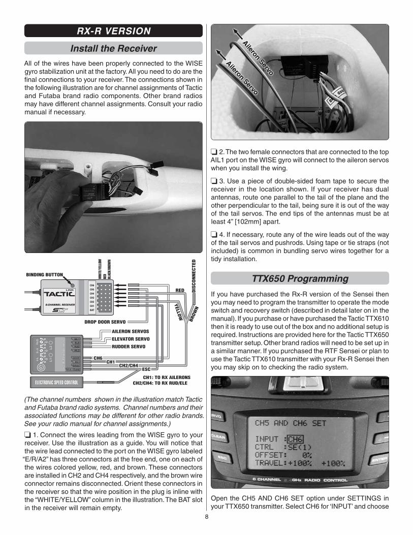
RX-R VERSION
Install the ReceiverAll of the wires have been properly connected to the WISE gyro stabilization unit at the factory. All you need to do are the fi nal connections to your receiver. The connections shown in the following illustration are for channel assignments of Tactic and Futaba brand radio components. Other brand radios may have different channel assignments. Consult your radio manual if necessary.
6-CHANNEL RECEIVER
LINK
SE
TA
IL
NR
EL
E
NR
RU
D
NR AIL1
AIL2
ELE
RUD
MODE
SYS
AIL1
E/R/A2
+ –
L1
L2
6-a
xis
Fli
gh
t C
on
tro
l
AILERON SERVOS
WHI
TE/Y
ELLO
WRE
DBL
ACK/
BROW
N
RED DIS
CO
NN
ECTE
D
YELLO
W
BROW
N
DROP DOOR SERVO
BINDING BUTTON
ELEVATOR SERVO
RUDDER SERVO
CH1: TO RX AILERONSCH2/CH4: TO RX RUD/ELE
CH6CH1
CH2/CH4ESC
(The channel numbers shown in the illustration match Tactic and Futaba brand radio systems. Channel numbers and their associated functions may be different for other radio brands. See your radio manual for channel assignments.)
❏ 1. Connect the wires leading from the WISE gyro to your receiver. Use the illustration as a guide. You will notice that the wire lead connected to the port on the WISE gyro labeled “E/R/A2” has three connectors at the free end, one on each of the wires colored yellow, red, and brown. These connectors are installed in CH2 and CH4 respectively, and the brown wire connector remains disconnected. Orient these connectors in the receiver so that the wire position in the plug is inline with the “WHITE/YELLOW” column in the illustration. The BAT slot in the receiver will remain empty.
❏ 2. The two female connectors that are connected to the top AIL1 port on the WISE gyro will connect to the aileron servos when you install the wing.
❏ 3. Use a piece of double-sided foam tape to secure the receiver in the location shown. If your receiver has dual antennas, route one parallel to the tail of the plane and the other perpendicular to the tail, being sure it is out of the way of the tail servos. The end tips of the antennas must be at least 4” [102mm] apart.
❏ 4. If necessary, route any of the wire leads out of the way of the tail servos and pushrods. Using tape or tie straps (not included) is common in bundling servo wires together for a tidy installation.
TTX650 Programming
If you have purchased the Rx-R version of the Sensei then you may need to program the transmitter to operate the mode switch and recovery switch (described in detail later on in the manual). If you purchase or have purchased the Tactic TTX610 then it is ready to use out of the box and no additional setup is required. Instructions are provided here for the Tactic TTX650 transmitter setup. Other brand radios will need to be set up in a similar manner. If you purchased the RTF Sensei or plan to use the Tactic TTX610 transmitter with your Rx-R Sensei then you may skip on to checking the radio system.
Open the CH5 AND CH6 SET option under SETTINGS in your TTX650 transmitter. Select CH6 for ‘INPUT’ and choose
9
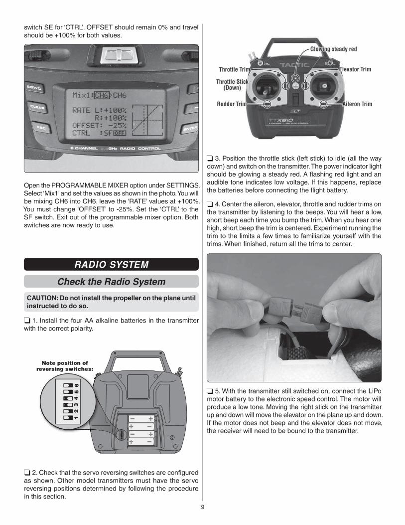
switch SE for ‘CTRL’. OFFSET should remain 0% and travel should be +100% for both values.
Open the PROGRAMMABLE MIXER option under SETTINGS. Select ‘Mix1’ and set the values as shown in the photo. You will be mixing CH6 into CH6. leave the ‘RATE’ values at +100%. You must change ‘OFFSET’ to -25%. Set the ‘CTRL’ to the SF switch. Exit out of the programmable mixer option. Both switches are now ready to use.
RADIO SYSTEM
Check the Radio System
CAUTION: Do not install the propeller on the plane until instructed to do so.
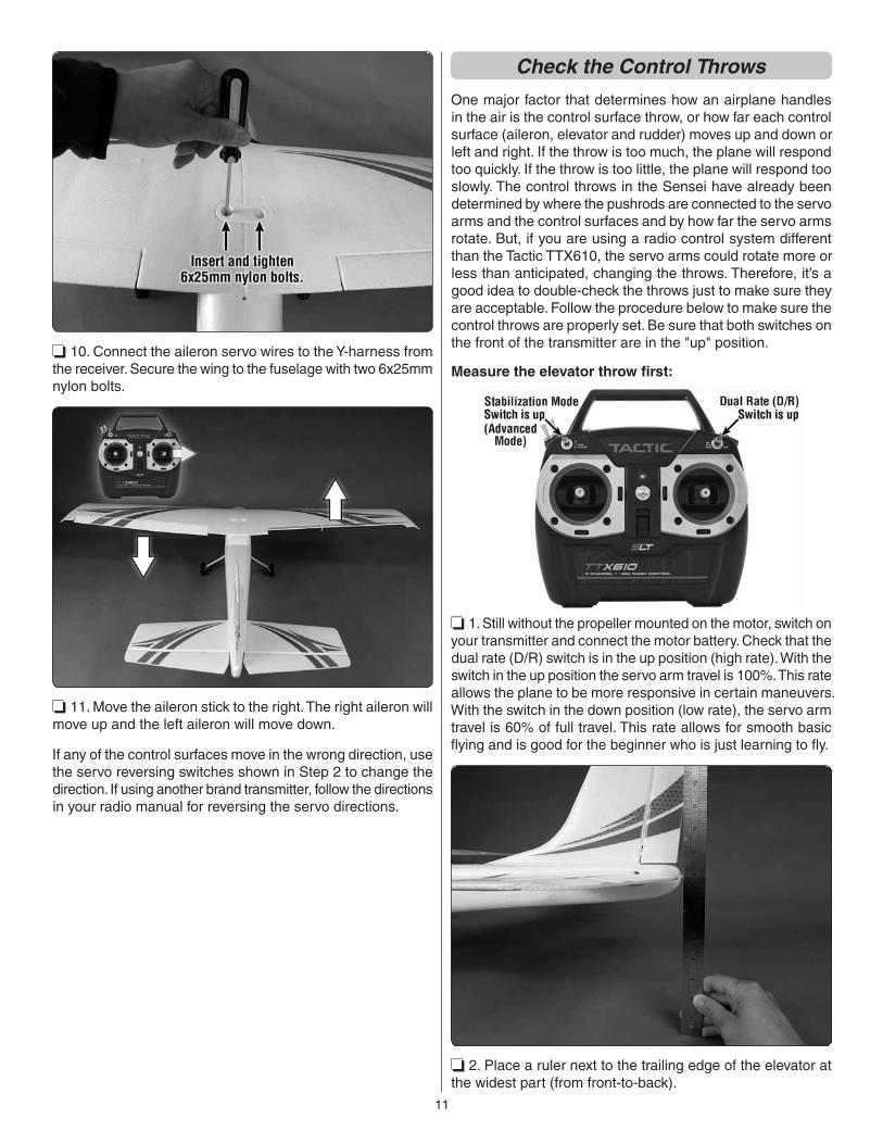
❏ 1. Install the four AA alkaline batteries in the transmitter with the correct polarity.
Note position ofreversing switches:
❏ 2. Check that the servo reversing switches are confi gured as shown. Other model transmitters must have the servo reversing positions determined by following the procedure in this section.
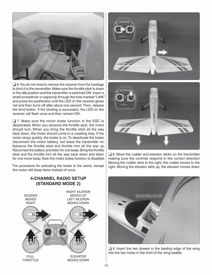
❏ 3. Position the throttle stick (left stick) to idle (all the way down) and switch on the transmitter. The power indicator light should be glowing a steady red. A fl ashing red light and an audible tone indicates low voltage. If this happens, replace the batteries before connecting the fl ight battery.
❏ 4. Center the aileron, elevator, throttle and rudder trims on the transmitter by listening to the beeps. You will hear a low, short beep each time you bump the trim. When you hear one high, short beep the trim is centered. Experiment running the trim to the limits a few times to familiarize yourself with the trims. When fi nished, return all the trims to center.
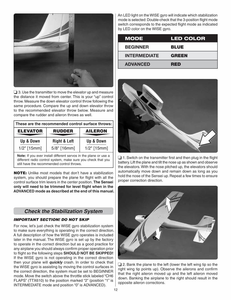
❏ 5. With the transmitter still switched on, connect the LiPo motor battery to the electronic speed control. The motor will produce a low tone. Moving the right stick on the transmitter up and down will move the elevator on the plane up and down. If the motor does not beep and the elevator does not move, the receiver will need to be bound to the transmitter.
10
❏ 6. You do not need to remove the receiver from the fuselage to bind it to the transmitter. Make sure the throttle stick is down in the idle position and the transmitter is switched ON. Insert a small screwdriver or paperclip through the hole marked “LINK” and press the pushbutton until the LED on the receiver glows red and then turns off after about one second. Then, release the bind button. If the binding is successful, the LED on the receiver will fl ash once and then remain ON.
❏ 7. Make sure the motor brake function in the ESC is deactivated. When you advance the throttle stick, the motor should turn. When you bring the throttle stick all the way back down, the motor should come to a coasting stop. If the motor stops quickly, the brake is on. To deactivate the brake, disconnect the motor battery, but leave the transmitter on. Advance the throttle stick and throttle trim all the way up. Reconnect the battery and listen for one beep. Bring the throttle stick and the throttle trim all the way back down and listen for one more beep. Now the motor brake function is disabled.
The procedure for activating the brake is the same, except the motor will beep twice instead of once.
FULLTHROTTLE
RUDDERMOVESRIGHT
ELEVATORMOVES DOWN
RIGHT AILERONMOVES UP
LEFT AILERONMOVES DOWN
4-CHANNEL RADIO SETUP(STANDARD MODE 2)
❏ 8. Move the rudder and elevator sticks on the transmitter making sure the controls respond in the correct direction. Moving the rudder stick to the right, the rudder moves to the right. Moving the elevator stick up, the elevator moves down.
❏ 9. Insert the two dowels in the leading edge of the wing into the two holes in the front of the wing saddle.
11
❏ 10. Connect the aileron servo wires to the Y-harness from the receiver. Secure the wing to the fuselage with two 6x25mm nylon bolts.
❏ 11. Move the aileron stick to the right. The right aileron will move up and the left aileron will move down.
If any of the control surfaces move in the wrong direction, use the servo reversing switches shown in Step 2 to change the direction. If using another brand transmitter, follow the directions in your radio manual for reversing the servo directions.
Check the Control Throws
One major factor that determines how an airplane handles in the air is the control surface throw, or how far each control surface (aileron, elevator and rudder) moves up and down or left and right. If the throw is too much, the plane will respond too quickly. If the throw is too little, the plane will respond too slowly. The control throws in the Sensei have already been determined by where the pushrods are connected to the servo arms and the control surfaces and by how far the servo arms rotate. But, if you are using a radio control system different than the Tactic TTX610, the servo arms could rotate more or less than anticipated, changing the throws. Therefore, it’s a good idea to double-check the throws just to make sure they are acceptable. Follow the procedure below to make sure the control throws are properly set. Be sure that both switches on the front of the transmitter are in the "up" position.
Measure the elevator throw fi rst:
❏ 1. Still without the propeller mounted on the motor, switch on your transmitter and connect the motor battery. Check that the dual rate (D/R) switch is in the up position (high rate). With the switch in the up position the servo arm travel is 100%. This rate allows the plane to be more responsive in certain maneuvers. With the switch in the down position (low rate), the servo arm travel is 60% of full travel. This rate allows for smooth basic fl ying and is good for the beginner who is just learning to fl y.
❏ 2. Place a ruler next to the trailing edge of the elevator at the widest part (from front-to-back).
12
❏ 3. Use the transmitter to move the elevator up and measure the distance it moved from center. This is your “up” control throw. Measure the down elevator control throw following the same procedure. Compare the up and down elevator throw to the recommended elevator throw below. Measure and compare the rudder and aileron throws as well.
These are the recommended control surface throws:
5/8" [16mm]
Right & Left
1/2" [15mm]
Up & Down
AILERON
1/2" [15mm]
Up & Down
RUDDERELEVATOR
Note: If you ever install different servos in the plane or use a different radio control system, make sure you check that you still have the recommended control throws.
NOTE: Unlike most models that don’t have a stabilization system, you should prepare the plane for fl ight with all the control surface trim levers in the center position. The Sensei only will need to be trimmed for level fl ight when in the ADVANCED mode as described at the end of this manual.
Check the Stabilization SystemIMPORTANT SECTION! DO NOT SKIP
For now, let’s just check the WISE gyro stabilization system to make sure everything is operating in the correct direction. A full description of how the WISE gyro operates is included later in the manual. The WISE gyro is set up by the factory to operate in the correct direction but as a good practice for any airplane you should always confi rm proper operation prior to fl ight so the following steps SHOULD NOT BE SKIPPED! If the WISE gyro is not operating in the correct direction then your plane will quickly crash. In order to check that the WISE gyro is assisting by moving the control surfaces in the correct direction, the system must be set to BEGINNER mode. Move the switch above the throttle stick labeled “CH6 FLAPS” (TTX610) to the position marked “2” (position “1” is INTERMEDIATE mode and position “0” is ADVANCED).
An LED light on the WISE gyro will indicate which stabilization mode is selected: Double-check that the 3-position fl ight mode switch corresponds to the expected fl ight mode as indicated by LED color on the WISE gyro.
MODE LED COLOR
BEGINNER BLUE
GREENINTERMEDIATE
REDADVANCED
❏ 1. Switch on the transmitter fi rst and then plug in the fl ight battery. Lift the plane and tilt the nose up as shown and observe the elevators. With the nose pitched up, the elevators should automatically move down and remain down as long as you hold the nose of the Sensei up. Repeat a few times to ensure proper correction direction.
❏ 2. Bank the plane to the left (lower the left wing tip so the right wing tip points up). Observe the ailerons and confi rm that the right aileron moved up and the left aileron moved down. Banking the airplane to the right should result in the opposite aileron corrections.
13
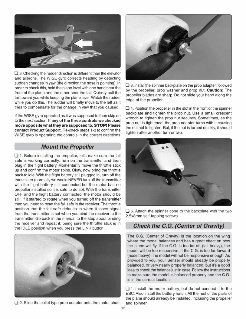
❏ 3. Checking the rudder direction is different than the elevator and ailerons. The WISE gyro corrects heading by detecting sudden changes in yaw (the direction the nose is pointing). In order to check this, hold the plane level with one hand near the front of the plane and the other near the tail. Quickly pull the tail toward you while keeping the plane level. Watch the rudder while you do this. The rudder will briefl y move to the left as it tries to compensate for the change in yaw that you caused.
If the WISE gyro operated as it was supposed to then skip on to the next section. If any of the three controls we checked move opposite what they are supposed to, STOP! Please contact Product Support. Re-check steps 1-3 to confi rm the WISE gyro is operating the controls in the correct directions.
Mount the Propeller
❏ 1. Before installing the propeller, let’s make sure the fail safe is working correctly. Turn on the transmitter and then plug in the fl ight battery. Momentarily move the throttle stick up and confi rm the motor spins. Okay, now bring the throttle back to idle. With the fl ight battery still plugged in, turn off the transmitter (normally we would NEVER turn off the transmitter with the fl ight battery still connected but the motor has no propeller installed so it is safe to do so). With the transmitter OFF and the fl ight battery connected, the motor should be still. If it started to rotate when you turned off the transmitter then you need to reset the fail safe in the receiver. The throttle position that the fail safe defaults to when it loses signal from the transmitter is set when you bind the receiver to the transmitter. Go back in the manual to the step about binding the receiver and repeat it, being sure the throttle stick is in the IDLE position when you press the LINK button.
❏ 2. Slide the collet type prop adapter onto the motor shaft.
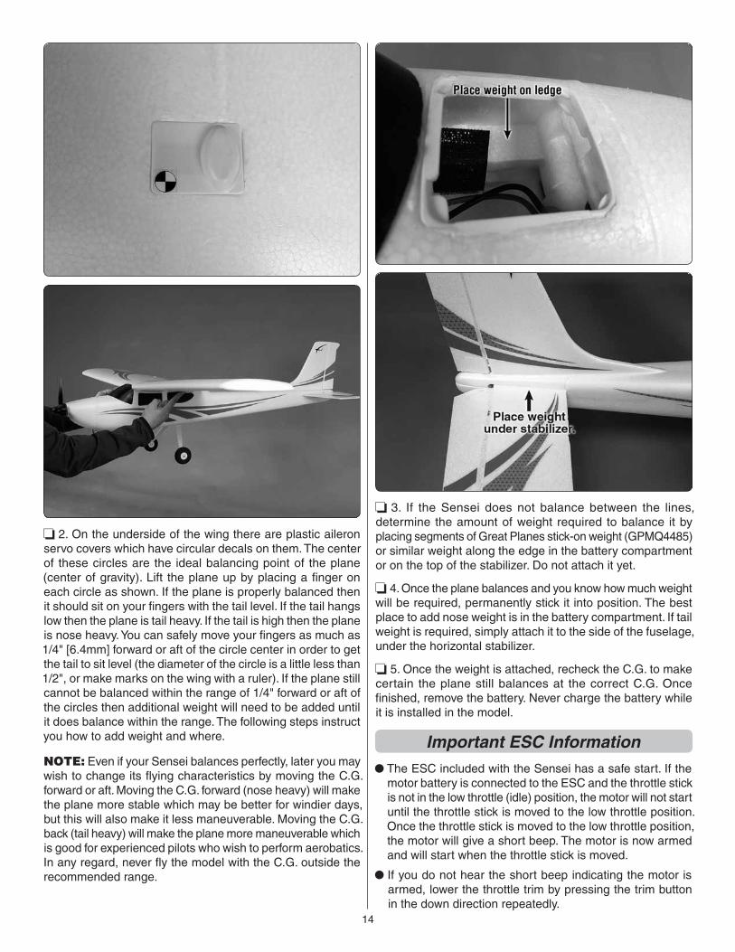
❏ 3. Install the spinner backplate on the prop adapter, followed by the propeller, prop washer and prop nut. Caution: The propeller blades are sharp. Do not slide your hand along the edge of the propeller.
❏ 4. Position the propeller in the slot in the front of the spinner backplate and tighten the prop nut. Use a small crescent wrench to tighten the prop nut securely. Sometimes, as the prop nut is tightened, the prop adapter turns with it causing the nut not to tighten. But, if the nut is turned quickly, it should tighten after another turn or two.
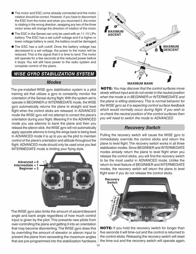
❏ 5. Attach the spinner cone to the backplate with the two 2.5x8mm self-tapping screws.
Check the C.G. (Center of Gravity)
The C.G. (Center of Gravity) is the location on the wing where the model balances and has a great effect on how the plane will fl y. If the C.G. is too far aft (tail heavy), the model will be too responsive. If the C.G. is too far forward (nose heavy), the model will not be responsive enough. As provided to you, your Sensei should already be properly balanced, or very nearly properly balanced, but it’s a good idea to check the balance just in case. Follow the instructions to make sure the model is balanced properly and the C.G. is in the correct location.
❏ 1. Install the motor battery, but do not connect it to the ESC. Also install the battery hatch. All the rest of the parts of the plane should already be installed, including the propeller and spinner.
14
❏ 2. On the underside of the wing there are plastic aileron servo covers which have circular decals on them. The center of these circles are the ideal balancing point of the plane (center of gravity). Lift the plane up by placing a fi nger on each circle as shown. If the plane is properly balanced then it should sit on your fi ngers with the tail level. If the tail hangs low then the plane is tail heavy. If the tail is high then the plane is nose heavy. You can safely move your fi ngers as much as 1/4" [6.4mm] forward or aft of the circle center in order to get the tail to sit level (the diameter of the circle is a little less than 1/2", or make marks on the wing with a ruler). If the plane still cannot be balanced within the range of 1/4" forward or aft of the circles then additional weight will need to be added until it does balance within the range. The following steps instruct you how to add weight and where.
NOTE: Even if your Sensei balances perfectly, later you may wish to change its fl ying characteristics by moving the C.G. forward or aft. Moving the C.G. forward (nose heavy) will make the plane more stable which may be better for windier days, but this will also make it less maneuverable. Moving the C.G. back (tail heavy) will make the plane more maneuverable which is good for experienced pilots who wish to perform aerobatics. In any regard, never fl y the model with the C.G. outside the recommended range.
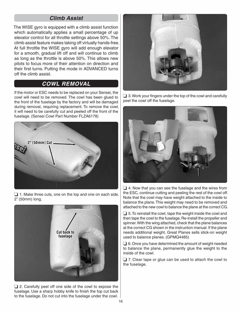
❏ 3. If the Sensei does not balance between the lines, determine the amount of weight required to balance it by placing segments of Great Planes stick-on weight (GPMQ4485) or similar weight along the edge in the battery compartment or on the top of the stabilizer. Do not attach it yet.
❏ 4. Once the plane balances and you know how much weight will be required, permanently stick it into position. The best place to add nose weight is in the battery compartment. If tail weight is required, simply attach it to the side of the fuselage, under the horizontal stabilizer.
❏ 5. Once the weight is attached, recheck the C.G. to make certain the plane still balances at the correct C.G. Once fi nished, remove the battery. Never charge the battery while it is installed in the model.
Important ESC Information● The ESC included with the Sensei has a safe start. If the
motor battery is connected to the ESC and the throttle stick is not in the low throttle (idle) position, the motor will not start until the throttle stick is moved to the low throttle position. Once the throttle stick is moved to the low throttle position, the motor will give a short beep. The motor is now armed and will start when the throttle stick is moved.
● If you do not hear the short beep indicating the motor is armed, lower the throttle trim by pressing the trim button in the down direction repeatedly.
15
● The motor and ESC come already connected and the motor rotation should be correct. However, if you have to disconnect the ESC from the motor and when you reconnect it, the motor is rotating in the wrong direction, swapping any two of the three motor wires will change the direction of rotation of the motor.
● The ESC in the Sensei can only be used with an 11.1V LiPo battery. The ESC has a set cutoff voltage and if a higher or lower voltage battery is used, the battery could be damaged.
● The ESC has a soft cutoff. Once the battery voltage has decreased to a set voltage, the power to the motor will be reduced. This is the signal that it is time to land. The motor will operate for a few seconds at the reduced power before it stops. You will still have power to the radio system and complete control of the plane.
WISE GYRO STABILIZATION SYSTEM
Modes
The pre-installed WISE gyro stabilization system is a pilot training aid that utilizes a gyro to constantly monitor the orientation of the Sensei during fl ight. With the system set to operate in BEGINNER or INTERMEDIATE mode, the WISE gyro automatically returns the plane to straight and level fl ight when the control sticks are released. In ADVANCED mode the WISE gyro will not attempt to correct the plane’s orientation during your fl ight. Meaning if in the ADVANCED mode you use ailerons to bank the plane and then you release the aileron stick, the WISE gyro will not automatically apply opposite ailerons to bring the wings back to being level. In ADVANCED mode it is up to you as the pilot to maintain control of the plane’s orientation and altitude throughout the fl ight. ADVANCED mode should only be used once you feel INTERMEDIATE mode is limiting your fl ying style.
Advanced = 0Intermediate = 1
Beginner = 2
The WISE gyro also limits the amount of ascent/descent angle and bank angle regardless of how much control input is given by the pilot. This prevents new pilots from over-controlling the plane and getting it into an orientation that may become disorienting. The WISE gyro does this by overriding the amount of elevator or aileron input to prevent the plane from exceeding the maximum angles that are pre-programmed into the stabilization hardware.
MAXIMUMASCENT
MAXIMUMDESCENT
MAXIMUM BANK
NOTE: You may discover that the control surfaces move slowly without input and do not center in the neutral position when the mode is in BEGINNER or INTERMEDIATE and the plane is sitting stationary. This is normal behavior for the WISE gyro as it is expecting control surface feedback which would normally occur during fl ight. If you wish to re-check the neutral position of the control surfaces then you will need to switch the mode to ADVANCED.
Recovery Switch
Pulling the recovery switch will cause the WISE gyro to immediately override the control sticks and return the plane to level fl ight. The recovery switch works in all three stabilization modes. Since BEGINNER and INTERMEDIATE modes already return the plane to level fl ight when you release the control sticks, you will fi nd the recovery switch to be the most useful in ADVANCED mode. Unlike the return-to-level feature of BEGINNER and INTERMEDIATE modes, the recovery switch will return the plane to level fl ight even if you do not release the control sticks.
RecoverySwitch
NOTE: If you hold the recovery switch for longer than fi ve seconds it will time-out and the control is returned to the control sticks. Releasing the recovery switch will reset the time-out and the recovery switch will operate again.
16
Climb Assist
The WISE gyro is equipped with a climb assist function which automatically applies a small percentage of up elevator control for all throttle settings above 50%. The climb assist feature makes taking off virtually hands-free. At full throttle the WISE gyro will add enough elevator for a smooth, gradual lift off and will continue to climb as long as the throttle is above 50%. This allows new pilots to focus more of their attention on direction and their fi rst turns. Putting the mode in ADVANCED turns off the climb assist.
COWL REMOVALIf the motor or ESC needs to be replaced on your Sensei, the cowl will need to be removed. The cowl has been glued to the front of the fuselage by the factory and will be damaged during removal, requiring replacement. To remove the cowl, it will need to be carefully cut and peeled off the front of the fuselage. (Sensei Cowl Part Number FLZA6178)
❏ 1. Make three cuts, one on the top and one on each side, 2” (50mm) long.
❏ 2. Carefully peel off one side of the cowl to expose the fuselage. Use a sharp hobby knife to fi nish the top cut back to the fuselage. Do not cut into the fuselage under the cowl.
❏ 3. Work your fi ngers under the top of the cowl and carefully peel the cowl off the fuselage.
❏ 4. Now that you can see the fuselage and the wires from the ESC, continue cutting and peeling the rest of the cowl off. Note that the cowl may have weight attached to the inside to balance the plane. This weight may need to be removed and attached to the new cowl to balance the plane at the correct CG.
❏ 5. To reinstall the cowl, tape the weight inside the cowl and then tape the cowl to the fuselage. Re-install the propeller and spinner. With the wing attached, check that the plane balances at the correct CG shown in the instruction manual. If the plane needs additional weight, Great Planes sells stick-on weight used to balance planes. (GPMQ4485)
❏ 6. Once you have determined the amount of weight needed to balance the plane, permanently glue the weight to the inside of the cowl.
❏ 7. Clear tape or glue can be used to attach the cowl to the fuselage.
17
GET THE MODEL READY TO FLY
Identify Your ModelNo matter if you fl y at an AMA sanctioned R/C club site or if you fl y somewhere on your own, you should always have your name, address, telephone number and AMA number on or inside your model. It is required at all AMA R/C club fl ying sites and AMA sanctioned fl ying events and simply a “good idea” even if fl ying somewhere else. Write this information on a strip of masking tape and place it on the inside of the model. The bottom center of the wing also makes a good location for the information.
Find a Suitable Flying SiteFind a fl ying site clear of buildings, trees, power lines and other obstructions. Until you know how much area will be required and have mastered fl ying your Sensei in confi ned spaces, a site at least the size of two or three football fi elds should be adequate – a fl ying fi eld specifi cally intended for R/C planes is best. Don’t fl y within fi ve miles of R/C fl ying fi elds and never fl y near people – especially children who can wander unpredictably into the fl ying area.
Know Your Frequency
CAUTION: This applies only to pilots fl ying their Sensei with a radio control system that broadcasts on 72MHz. This caution does not apply to pilots fl ying their Sensei on 2.4GHz. The Tactic TTX610 operates on 2.4GHz
Transmitters operating on 72MHz operate on one of several frequencies available. To fi nd your frequency (or “channel”), look at the label on the transmitter. If your channel happens to be the same as another model that is being fl own nearby (even within a few miles), one or both models will crash. Know your frequency and be aware of the frequency of other models that are fl ying nearby—especially if you are fl ying at a radio control fl ying site. All fl ying sites have some sort of frequency control system to avoid this kind of interference, so learn how to use their frequency control system. Never turn on your transmitter until you are certain that you will be the only one operating on your frequency.
Perform a Range CheckAs a precaution, an operational ground range test should be performed before the fi rst fl ight each time you go out. Performing a range test is a good way to detect problems that could cause loss of control such as low batteries, defective or damaged radio components or radio interference. This usually requires an assistant and should be done at the actual fl ying site you will be using.
First switch on the transmitter, then install the fully-charged battery into the fuselage. Connect the battery and install the battery hatch.
Remember, use care not to “bump” the throttle stick. Otherwise, the propeller will turn and possibly cause damage or injury.
To range check the Tactic TTX610 radio control system, switch on the transmitter and connect the motor battery to the ESC. Set the model on the ground and have an assistant hold the model. Walk 100’ (90m) from the model and while pointing the transmitter at the plane, operate the controls ensuring that the plane’s surfaces operate according to the transmitter inputs. Operate the motor at different RPMs. Have your assistant alert you if the controls quit responding or move suddenly or erratically. If you are using a different radio control system, follow the instructions that came with your radio control system to perform a ground range check.
If the controls aren’t working correctly or if anything seems wrong, don’t fl y the model until you fi nd and correct the problem. Make certain all the servo wires are securely connected to the receiver and the transmitter batteries are in good condition.
Monitor Your Flight TimeMonitor and limit your fl ight time using a timer (such as one on a wrist watch or in your transmitter if yours has one). When the batteries are getting low you will usually notice a performance drop before the ESC cuts off motor power, so when the plane starts fl ying slower you should land.
To avoid an unexpected dead-stick landing on your fi rst fl ight, set your timer to a conservative 4 minutes (in most conditions the Sensei will usually fl y for approximately 5 minutes, but this can vary). When your alarm sounds you can either land right away, or if you are an experienced pilot you may continue to fl y until the motor fi nally quits. Then, glide it in for a landing. If planning a “dead-stick,” circle your Sensei upwind of the landing area until the motor quits and note the run time.
When you learn how much fl ight time you are getting you can adjust your timer accordingly. Always be conservative so the motor won’t quit unexpectedly and you will have enough battery to land under power.
FLYINGNote to new pilots: Read and understand this entire section before attempting your fi rst fl ight.
The Sensei is a great-fl ying trainer that fl ies smoothly and predictably. The addition of the WISE gyro stabilization system to an already stable airframe greatly improves the success rate of beginning pilots learning without an instructor. However, nothing replaces the advantage of having an experienced R/C pilot at your side helping you with your fi rst few fl ights. If you have any doubts about your ability to learn to fl y by yourself then we encourage you seek out help. Your local R/C fl ying fi eld should be your fi rst stop in seeking help and is will be the best, safest location for your fl ights anyhow. The AMA (Academy of Model Aeronautics) website, modelaircraft.org, has a wealth of information about fl ight instruction.
18
CAUTION (THIS APPLIES TO ALL R/C AIRPLANES): If, while fl ying, you notice an alarming or unusual sound such as a low-pitched “buzz,” this may indicate control surface fl utter. Flutter occurs when a control surface (such as an aileron or elevator) or a fl ying surface (such as a wing or stab) rapidly vibrates up and down (thus causing the noise). In extreme cases, if not detected immediately, fl utter can actually cause the control surface to detach or the fl ying surface to fail, thus causing loss of control followed by an impending crash. The best thing to do when fl utter is detected is to slow the model immediately by reducing power, then land as soon as safely possible. Identify which surface fl uttered (so the problem may be resolved) by checking all the servo grommets for deterioration or signs of vibration. Make certain all pushrod linkages are secure and free of play. If it fl uttered once, under similar circumstances it will probably fl utter again unless the problem is fi xed. Some things which can cause fl utter are; Excessive hinge gap; Not mounting control horns solidly; Poor fi t of clevis pin in horn; Side-play of wire pushrods caused by large bends; Excessive free play in servo gears; Insecure servo mounting; and one of the most prevalent causes of fl utter; Flying an over-powered model at excessive speeds.
TakeoffBefore you get ready to take off, see how the Sensei handles on the ground by doing a few practice runs at low speed on the runway. Note the amount of rudder steering required to turn the plane. If you need to calm your nerves before the maiden fl ight, bring the plane back to the pits, unplug and remove the battery and peak charge it.
It is best to make the fi rst couple of fl ights with the sun at your back. With the sun directly overhead the bottom of the plane is in shadow and can sometime confuse the beginner pilot. Do not take the fi rst fl ights with the sun in front of you. Experienced pilots that have better control of the plane can avoid fl ying into the sun.
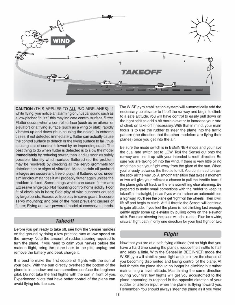
The WISE gyro stabilization system will automatically add the necessary up elevator to lift off the runway and begin to climb to a safe altitude. You will have control to easily pull down on the right stick to add a bit more elevator to increase your rate of climb on take off if necessary. With that in mind, your main focus is to use the rudder to steer the plane into the traffi c pattern (the direction that the other modelers are fl ying their planes) once you get into the air.
Be sure the mode switch is in BEGINNER mode and you have the dual rate switch set to LOW. Taxi the Sensei out onto the runway and line it up with your intended takeoff direction. Be sure you are taking off into the wind. If there is very little or no wind then plan your fl ight away from the glare of the sun. When you’re ready, advance the throttle to full. You don’t need to slam the stick all the way up. A smooth transition that takes a moment or two will give your refl exes a chance to pull the throttle back if the plane gets off track or there is something else alarming. Be prepared to make small corrections with the rudder to keep its takeoff path straight, just as if you were to steer an automobile on a highway. You’ll see the plane get “light” on the wheels. Then it will lift off and begin to climb. At full throttle the Sensei will continue to gain altitude. If you feel the plane is not climbing fast enough, gently apply some up elevator by pulling down on the elevator stick. Focus on steering the plane with the rudder. Plan for a wide, circular fl ight path in only one direction for your fi rst fl ight or two.
FlightNow that you are at a safe fl ying altitude (not so high that you have a hard time seeing the plane), reduce the throttle to half and relax a little. With the Sensei in BEGINNER mode the WISE gyro will stabilize your fl ight and minimize the chance of you becoming disoriented and losing control of the plane. At half throttle the plane should no longer be climbing but rather maintaining a level altitude. Maintaining the same direction during your fi rst few fl ights will get you accustomed to the plane appearing to respond in the opposite direction of your rudder or aileron input when the plane is fl ying toward you. Remember- You should always steer the plane as if you were
TAKEOFF
19
sitting in the cockpit. If you fi nd this diffi cult, try turning your back to the plane when it is fl ying toward you and watch the plane by looking over your shoulder.
Don’t forget about your fl ight timer. Be sure to allow yourself a minute, maybe two, to plan and execute your landing approach. Use the time until landing to experiment with the ailerons and elevator. As you progress with your pilot skills you will fi nd yourself turning mostly with a combination of ailerons and some up elevator. Try this out. Remember, BEGINNER mode will reduce the effectiveness of this and you will prefer rudder turns for now. When you fl y in ADVANCED mode you will make aileron turns more frequently.
LandingAt this point you only have a minute or two left on your timer so it’s time to prepare for landing. Don’t worry if you overshoot your planned landing spot or come up short. As long as the plane will touch down in an area free of obstacles (and people), just let it land. You’ll have plenty of chances later to hone your landing approaches. For now, we just want the plane safely down with a little battery charge left. If you have enough fl ight time left in your battery then you can afford to try a couple “practice” landings before the real thing. This means you would approach your landing spot and reduce throttle, but actually targeting an imaginary runway 15 or 20 feet in the air above the real runway.
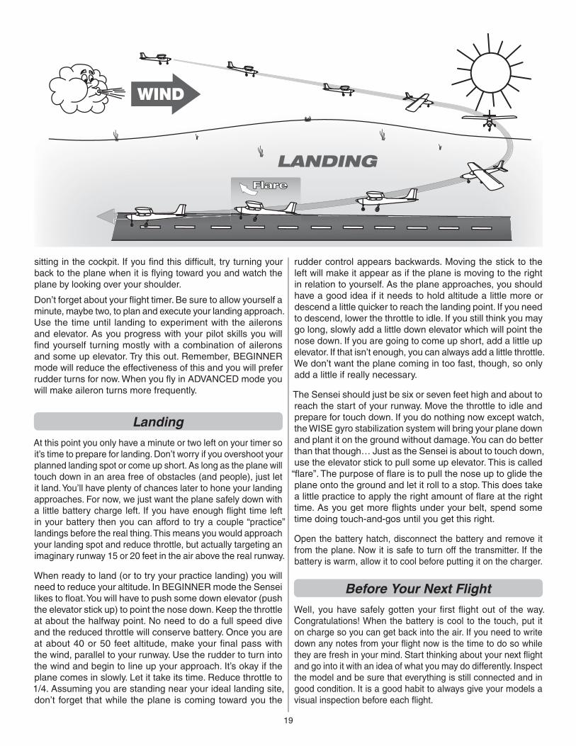
When ready to land (or to try your practice landing) you will need to reduce your altitude. In BEGINNER mode the Sensei likes to fl oat. You will have to push some down elevator (push the elevator stick up) to point the nose down. Keep the throttle at about the halfway point. No need to do a full speed dive and the reduced throttle will conserve battery. Once you are at about 40 or 50 feet altitude, make your fi nal pass with the wind, parallel to your runway. Use the rudder to turn into the wind and begin to line up your approach. It’s okay if the plane comes in slowly. Let it take its time. Reduce throttle to 1/4. Assuming you are standing near your ideal landing site, don’t forget that while the plane is coming toward you the
rudder control appears backwards. Moving the stick to the left will make it appear as if the plane is moving to the right in relation to yourself. As the plane approaches, you should have a good idea if it needs to hold altitude a little more or descend a little quicker to reach the landing point. If you need to descend, lower the throttle to idle. If you still think you may go long, slowly add a little down elevator which will point the nose down. If you are going to come up short, add a little up elevator. If that isn’t enough, you can always add a little throttle. We don’t want the plane coming in too fast, though, so only add a little if really necessary.
The Sensei should just be six or seven feet high and about to reach the start of your runway. Move the throttle to idle and prepare for touch down. If you do nothing now except watch, the WISE gyro stabilization system will bring your plane down and plant it on the ground without damage. You can do better than that though… Just as the Sensei is about to touch down, use the elevator stick to pull some up elevator. This is called “fl are”. The purpose of fl are is to pull the nose up to glide the plane onto the ground and let it roll to a stop. This does take a little practice to apply the right amount of fl are at the right time. As you get more fl ights under your belt, spend some time doing touch-and-gos until you get this right.
Open the battery hatch, disconnect the battery and remove it from the plane. Now it is safe to turn off the transmitter. If the battery is warm, allow it to cool before putting it on the charger.
Before Your Next FlightWell, you have safely gotten your fi rst fl ight out of the way. Congratulations! When the battery is cool to the touch, put it on charge so you can get back into the air. If you need to write down any notes from your fl ight now is the time to do so while they are fresh in your mind. Start thinking about your next fl ight and go into it with an idea of what you may do differently. Inspect the model and be sure that everything is still connected and in good condition. It is a good habit to always give your models a visual inspection before each fl ight.
LANDINGFlare
Improving Your Piloting SkillsAfter you have made several fl ights in BEGINNER mode you can try switching it to INTERMEDIATE mode. It operates the same way as BEGINNER mode. However, the maximum amount of ascent and descent are greater as well as the bank amount. A few more fl ights in INTERMEDIATE mode should prepare you to turn off the training functions and move on to ADVANCED mode. Remember, in ADVANCED mode there are no limitations to the controls. You will now be able to make quick turns using the ailerons to bank the plane and applying up elevator to pull the plane through the turn. You will also be able to execute loops, rolls and other basic aerobatic manuevers. Take off in INTERMEDIATE mode and climb to a safe altitude before switching to ADVANCED mode. The fi rst thing you will want to do once you switch to ADVANCED mode is to try out the recovery function. At a safe altitude use ailerons to roll the plane on its side. Now reach up and pull the recovery switch. The plane quickly corrects itself back to level fl ight. Whenever you feel you have lost orientation of the Sensei don’t hesitate to pull the recovery switch.
TrimmingOnce switched to ADVANCED mode, be prepared for the need to add trim. In BEGINNER and INTERMEDIATE modes adding trim was not necessary as the stabilization system would make the necessary corrections for the plane to fl y straight and level. In ADVANCED mode the system is no longer helping in that way so you may fi nd the plane to stray from level fl ight if you release the sticks. If it looks like it’s rolling or leaning to the left, then add clicks of right aileron trim until it levels out. The opposite if it leans to the right. Does the plane still seem to be climbing or descending any at half throttle? It may take a few laps around your fl ying site to decide that. If so, add a few clicks of up or down elevator trim as needed. Rudder is more diffi cult to determine during fl ight but if you notice any signifi cant drift in heading then make the appropriate rudder trim correction.
If you have made any signifi cant trim changes (more than 4 clicks of one or more trim buttons), do not switch back to BEGINNER or INTERMEDIATE mode until after you have landed the plane. When landed, unplug the fl ight battery and then reconnect it. The trim changes you made will now become the new “neutral points” in the stabilization system. Failure to reset the system by cycling the power of the plane may cause the plane to no longer fl y straight and level in BEGINNER or INTERMEDIATE modes.
With the training functions now off, you will discover that the plane does what you tell it to do. Fly slow and stay high. Practice your aileron turns and try some fi gure 8 patterns. Pitch the nose of the plane up with some up elevator and try a full roll. When you are comfortable with having full control of the plane, you can then try out the high rate switch.
Some fi nal thoughts for the beginner pilot. Before taking off, always have a fl ight plan, determine which direction you’re going to fl y, how high, what you want to work on, keeping the plane level through turns or fl ying coordinated turns with rudder (in ADVANCED mode). You do not want to surprise yourself by trying a maneuver such as a loop and fi nding out you were not high enough. Learn the basic fl ying skills well. All maneuvers are based on having full control of the plane. So go out and practice, practice, practice.
GOOD LUCK!


![flz, phstg arXiv:1711.06025v2 [cs.CV] 27 Mar 2018 · 1Queen Mary University of London 2University of Oxford 3The University of Edinburgh floodsung@gmail.com t.xiang@qmul.ac.uk flz,](https://img.pdfslide.net/doc/110x75/5f6088302e3bf93cfb096040/flz-phstg-arxiv171106025v2-cscv-27-mar-2018-1queen-mary-university-of-london.jpg)


![INSTRUCTION MANUAL - Hobbico, Inc. - largest U.S ...manuals.hobbico.com/flz/flza2102-manual.pdfFLZA2102 SPECIFICATIONS Wingspan: 15.9 in [404mm] Total Length: 15.7 in [399mm] Weight:](https://img.pdfslide.net/doc/110x75/5aa505477f8b9ae7438cd38c/instruction-manual-hobbico-inc-largest-us-specifications-wingspan-159.jpg)