Embed Size (px)
Citation preview
flyzoneplanes.com
™
© 2015 Flyzone, a Hobbico company.
Wingspan: 25 in [635mm]Wing Area: 141 sq in [9.1 dm2]Weight: 24–25 oz [680–710g]Wing Loading: 24.5–25.5 oz/sq ft [75–78 g/dm2]Length: 31 in [785mm]Radio: 3-Channel Minimum
WARRANTYFlyzone® guarantees this kit to be free from defects in both material and workmanship at the date of purchase. This warranty does not cover any component parts damaged by use or modification. In no case shall Flyzone’s liability exceed the original cost of the purchased kit. Further, Flyzone reserves the right to change or modify this warranty without notice.
In that Flyzone has no control over the final assembly or material used for final assembly, no liability shall be assumed nor accepted for any damage resulting from the use by the user of the final user-assembled product. By the act of using the user-assembled product, the user accepts all resulting liability.
If the buyer is not prepared to accept the liability associated with the use of this product, the buyer is advised to return this kit immediately in new and unused condition to the place of purchase.
Thank you for purchasing the latest version of the Flyzone L-39. A more powerful motor is now included which will enable speeds approaching 100mph! The L-39 flies like it’s on rails and the vibrant color scheme looks great as it cuts across a blue horizon. Durable EPO foam construction resists damage from bumpy landings and repairs easily with regular CA glue. A display stand is included to show off your model on your trophy shelf when it’s not busy carving up the skies above your flying field!
For the latest technical updates or manual corrections to the L-39 visit the Flyzone web site at www.flyzoneplanes.com. Open the “Airplanes” link, then select the L-39. If there is new technical information or changes to this model a “tech notice” box will appear in the upper left corner of the page.
For warranty claims contact Flyzone Product Support:Flyzone Product Support:3002 N Apollo Drive Suite 1Champaign, IL 61822 USA
Telephone: (217) 398-8970 ext. 6Fax: (217) 398-7721E-mail: [email protected]
READ THROUGH THIS MANUAL BEFORE STARTING ASSEMBLY. IT CONTAINS IMPORTANT INSTRUCTIONS AND WARNINGS CONCERNING THE ASSEMBLY AND USE OF THIS MODEL.
FLZA3634Mnl
2
WARNING!The L-39 requires advanced flying skills and is not suitable for beginning or intermediate pilots. It reaches speeds of over 90 mph (145 km/h) and should be flown only at the flying site of an AMA-chartered club. Because it can quickly disappear from sight, pilots should remain focused on the plane at all times.
DECISIONS YOU MUST MAKEThis is a partial list of items required to finish the L-39 EDF that may require planning or decision making before starting to build. Order numbers are provided in parentheses.
Radio EquipmentThe L-39 EDF requires a 3+ channel transmitter and a receiver. If you already have a transmitter you are going to use to fly the L-39, you can get the receiver separately:
❍ Futaba 617FS FASST 2.4 GHz receiver [FUTL7637]
OR❍ Tactic TR624 6-Channel 2.4GHz SLT Receiver
Using the Tactic AnyLink2 2.4GHz Universal Radio Adapter (TACJ2005) will make virtually any transmitter with a trainer port compatIble with the above mentioned Tactic receiver. Optional cables available through your hobby supplier may be necessary to use the AnyLink2 with some transmitters.
A lithium-polymer battery pack and suitable charger are also required (batteries larger than the recommended Great Planes LiPo may not fit in the battery compartment):
❍ Great Planes ElectriFly LiPo 4S 14.8V 2200mAh 30C (GPMP0862)❍ Great Planes ElectriFly Triton EQ AC/DC Charger (GPMM3155)
ADDITIONAL ITEMS REQUIREDAdhesives and Building SuppliesFoam safe CA glue and 30-minute epoxy are used in the assembly of the L-39. Order numbers are provided below:
❍ Great Planes Pro™ Epoxy 30-Minute Formula 4 oz. (GPMR6043)
❍ Great Planes Pro Foam Safe CA- Thick Glue 1 oz. (GPMR6072) (used for display stand assembly)
❍ Denatured alcohol (for epoxy clean up)
This manual also refers to using a #60 [.040"] and a 3/64" [1.2mm] drill bit:
❍ Hobbico® Pin Vise 1/16 Collet w/6 Bits (HCAR0696)
Optional Supplies and ToolsHere is a list of items that will help you build the L-39:
❍ CA debonder (GPMR6039)❍ Epoxy brushes (6, GPMR8060)❍ Mixing sticks (50, GPMR8055)❍ Mixing cups (GPMR8056)❍ CG Machine™ (GPMR2400)❍ Hobbico Flexible 18" Ruler Stainless Steel (HCAR0460)
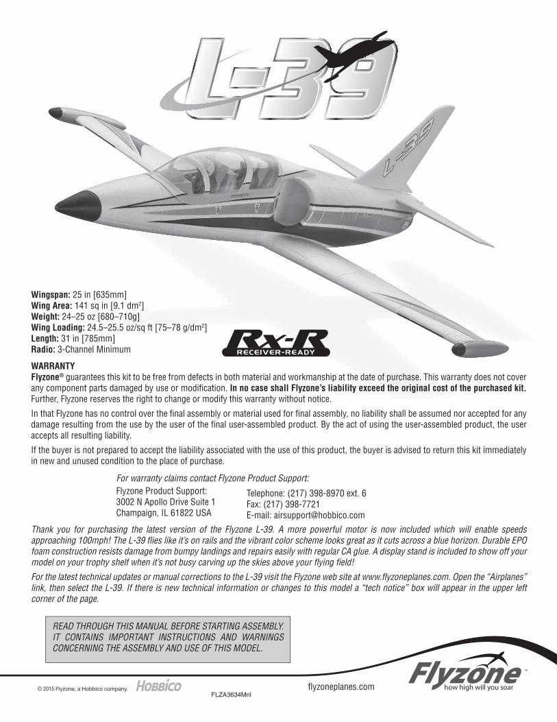
BEFORE YOU BEGIN
❏ Before building the model, please follow the break-in instructions found on page 10 of this manual.
3
ASSEMBLE THE AIRPLANE
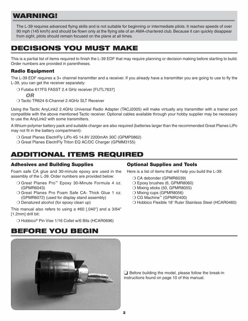
❏ 1. Attach a 6" [152mm] servo extension to the ESC receiver lead. Secure the extension with tape or heatshrink tubing (not included).
❏ 2. Route the motor wires and ESC lead along the underside of the fuselage and through the hole into the radio compartment. Trace around the servo extension connector as it fits in the wire channel. Cut away the foam inside your traced lines so that the connector sits flush inside the channel. A small piece of double-sided tape (not included) will hold it in place.
❏ 3. Coat the wing saddle on the fuselage with 30-minute epoxy. Insert the aileron servo wires through the hole in the fuse and into the radio compartment. Place the wing onto the saddle by fitting the alignment keys on the top of the wing into the mating cutouts in the wing saddle. Tape the wing to the fuse while the epoxy cures or place a weight on the top of the fuse (recommended) to press it against the wing (prop the plane up between the aileron control horns so it doesn’t damage the aileron hinges). If using tape, avoid damaging the paint by first lining the outside of the model with sheets of paper or something similar. Wrap the tape tightly around the paper instead of directly onto the model.
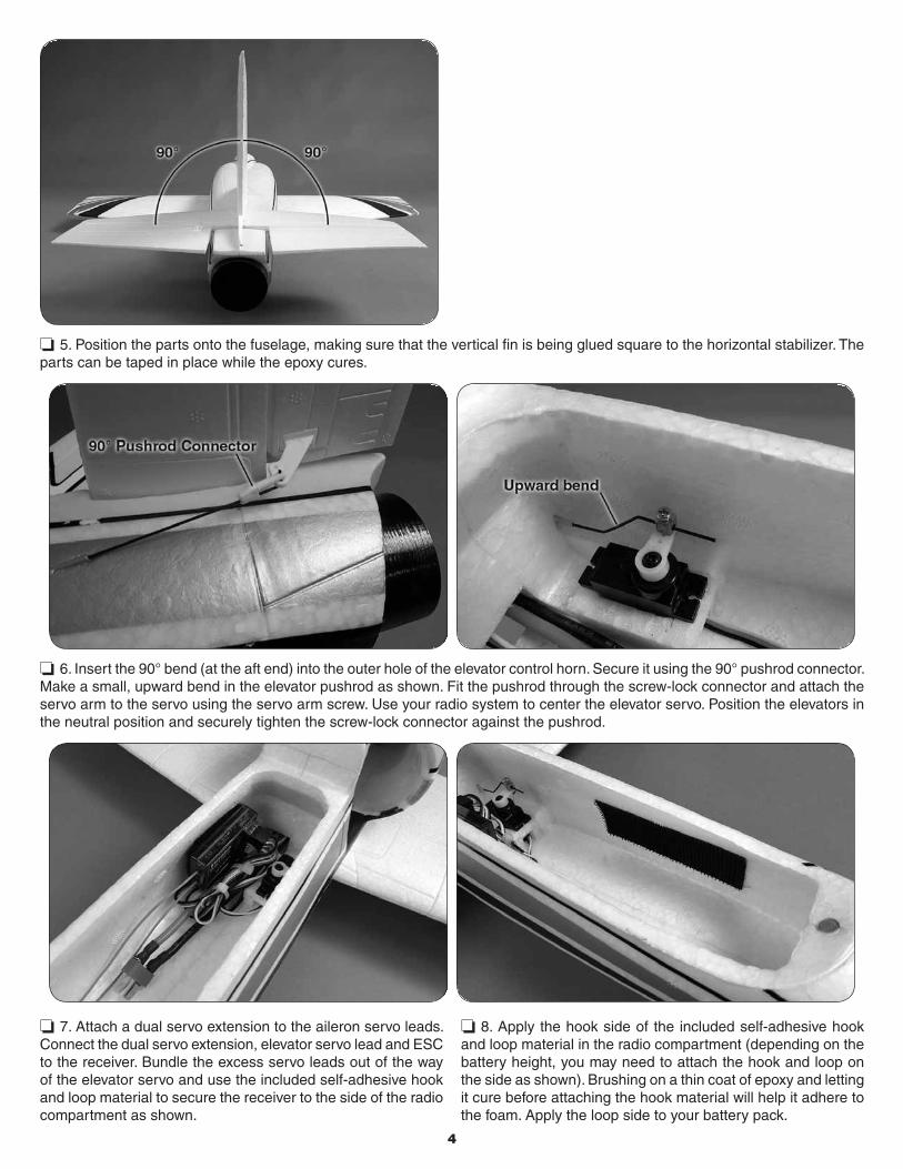
❏ 4. The vertical fin and horizontal stabilizer are keyed to fit together and it is recommended that they be glued in place at the same time. Coat with epoxy the key on the bottom of the fin, the slot in the horizontal stabilizer, and the stab saddle on the fuselage. Do not put epoxy on the front of the fin that fits into the ducted fan access hatch. The hatch must remain removable.
4
❏ 5. Position the parts onto the fuselage, making sure that the vertical fin is being glued square to the horizontal stabilizer. The parts can be taped in place while the epoxy cures.
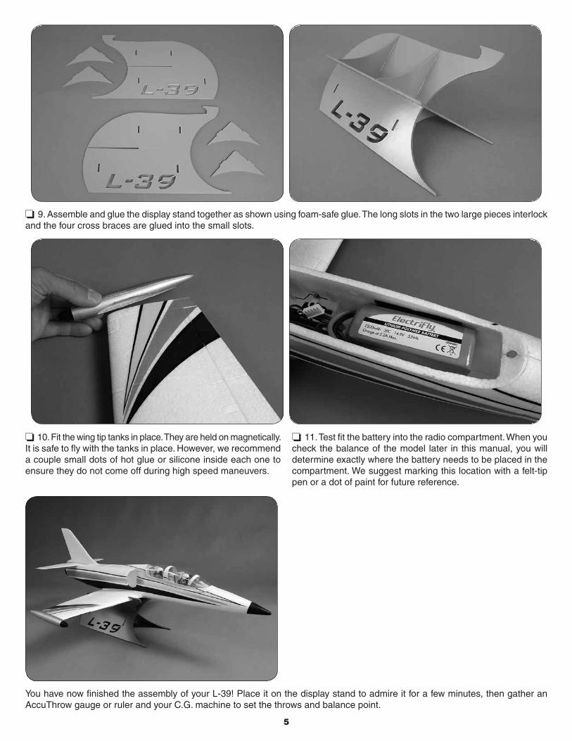
❏ 6. Insert the 90° bend (at the aft end) into the outer hole of the elevator control horn. Secure it using the 90° pushrod connector. Make a small, upward bend in the elevator pushrod as shown. Fit the pushrod through the screw-lock connector and attach the servo arm to the servo using the servo arm screw. Use your radio system to center the elevator servo. Position the elevators in the neutral position and securely tighten the screw-lock connector against the pushrod.
❏ 7. Attach a dual servo extension to the aileron servo leads. Connect the dual servo extension, elevator servo lead and ESC to the receiver. Bundle the excess servo leads out of the way of the elevator servo and use the included self-adhesive hook and loop material to secure the receiver to the side of the radio compartment as shown.
❏ 8. Apply the hook side of the included self-adhesive hook and loop material in the radio compartment (depending on the battery height, you may need to attach the hook and loop on the side as shown). Brushing on a thin coat of epoxy and letting it cure before attaching the hook material will help it adhere to the foam. Apply the loop side to your battery pack.
5
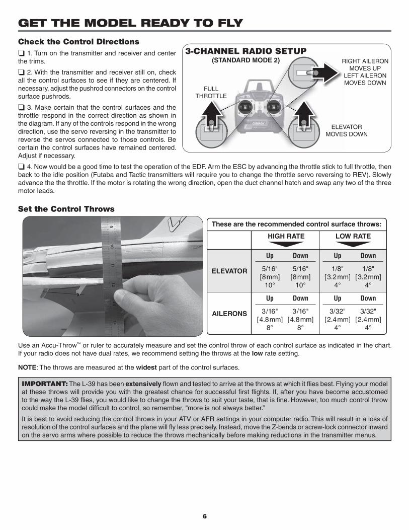
❏ 9. Assemble and glue the display stand together as shown using foam-safe glue. The long slots in the two large pieces interlock and the four cross braces are glued into the small slots.
❏ 10. Fit the wing tip tanks in place. They are held on magnetically. It is safe to fly with the tanks in place. However, we recommend a couple small dots of hot glue or silicone inside each one to ensure they do not come off during high speed maneuvers.
❏ 11. Test fit the battery into the radio compartment. When you check the balance of the model later in this manual, you will determine exactly where the battery needs to be placed in the compartment. We suggest marking this location with a felt-tip pen or a dot of paint for future reference.
You have now finished the assembly of your L-39! Place it on the display stand to admire it for a few minutes, then gather an AccuThrow gauge or ruler and your C.G. machine to set the throws and balance point.
6
GET THE MODEL READY TO FLY
Check the Control Directions❏ 1. Turn on the transmitter and receiver and center the trims.
❏ 2. With the transmitter and receiver still on, check all the control surfaces to see if they are centered. If necessary, adjust the pushrod connectors on the control surface pushrods.
❏ 3. Make certain that the control surfaces and the throttle respond in the correct direction as shown in the diagram. If any of the controls respond in the wrong direction, use the servo reversing in the transmitter to reverse the servos connected to those controls. Be certain the control surfaces have remained centered. Adjust if necessary.
❏ 4. Now would be a good time to test the operation of the EDF. Arm the ESC by advancing the throttle stick to full throttle, then back to the idle position (Futaba and Tactic transmitters will require you to change the throttle servo reversing to REV). Slowly advance the the throttle. If the motor is rotating the wrong direction, open the duct channel hatch and swap any two of the three motor leads.
Set the Control Throws
These are the recommended control surface throws:
ELEVATOR
LOW RATE
AILERONS
HIGH RATE
1/8"[3.2mm]
4°
Up
3/32"[2.4mm]
4°
Up
5/16"[8mm]
10°
Up
3/16"[4.8mm]
8°
Up
1/8"[3.2mm]
4°
Down
3/32"[2.4mm]
4°
Down
5/16"[8mm]
10°
Down
3/16"[4.8mm]
8°
Down
Use an Accu-Throw™ or ruler to accurately measure and set the control throw of each control surface as indicated in the chart. If your radio does not have dual rates, we recommend setting the throws at the low rate setting.
NOTE: The throws are measured at the widest part of the control surfaces.
IMPORTANT: The L-39 has been extensively flown and tested to arrive at the throws at which it flies best. Flying your model at these throws will provide you with the greatest chance for successful first flights. If, after you have become accustomed to the way the L-39 flies, you would like to change the throws to suit your taste, that is fine. However, too much control throw could make the model difficult to control, so remember, “more is not always better.”
It is best to avoid reducing the control throws in your ATV or AFR settings in your computer radio. This will result in a loss of resolution of the control surfaces and the plane will fly less precisely. Instead, move the Z-bends or screw-lock connector inward on the servo arms where possible to reduce the throws mechanically before making reductions in the transmitter menus.
FULLTHROTTLE
ELEVATORMOVES DOWN
RIGHT AILERONMOVES UP
LEFT AILERONMOVES DOWN
R
L
3-CHANNEL RADIO SETUP(STANDARD MODE 2)
7
Balance the Model
More than any other factor, the C.G. (balance point) can have the greatest effect on how a model flies, and may determine whether or not your first flight will be successful. If you value this model and wish to enjoy it for many flights, DO NOT OVERLOOK THIS IMPORTANT PROCEDURE. A model that is not properly balanced will be unstable and possibly unflyable.
At this stage the model should be in ready-to-fly condition with all of the systems in place including the receiver, ESC, and battery pack.
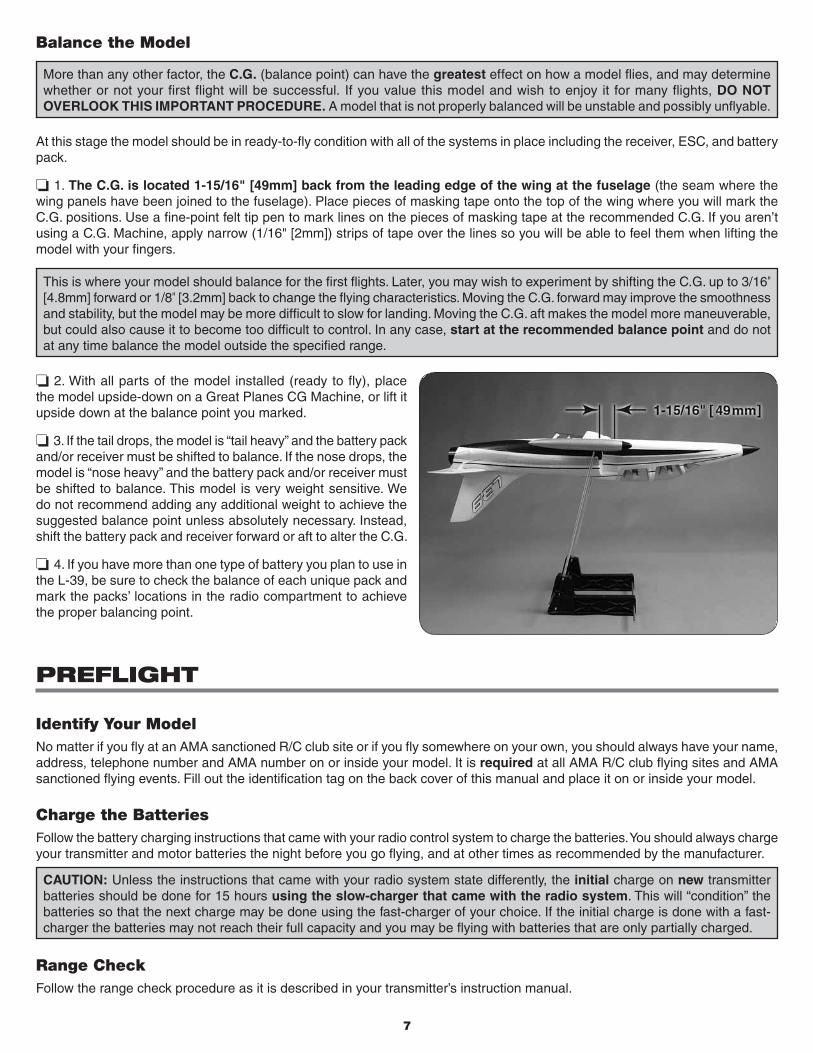
❏ 1. The C.G. is located 1-15/16" [49mm] back from the leading edge of the wing at the fuselage (the seam where the wing panels have been joined to the fuselage). Place pieces of masking tape onto the top of the wing where you will mark the C.G. positions. Use a fine-point felt tip pen to mark lines on the pieces of masking tape at the recommended C.G. If you aren’t using a C.G. Machine, apply narrow (1/16" [2mm]) strips of tape over the lines so you will be able to feel them when lifting the model with your fingers.
This is where your model should balance for the first flights. Later, you may wish to experiment by shifting the C.G. up to 3/16" [4.8mm] forward or 1/8" [3.2mm] back to change the flying characteristics. Moving the C.G. forward may improve the smoothness and stability, but the model may be more difficult to slow for landing. Moving the C.G. aft makes the model more maneuverable, but could also cause it to become too difficult to control. In any case, start at the recommended balance point and do not at any time balance the model outside the specified range.
❏ 2. With all parts of the model installed (ready to fly), place the model upside-down on a Great Planes CG Machine, or lift it upside down at the balance point you marked.
❏ 3. If the tail drops, the model is “tail heavy” and the battery pack and/or receiver must be shifted to balance. If the nose drops, the model is “nose heavy” and the battery pack and/or receiver must be shifted to balance. This model is very weight sensitive. We do not recommend adding any additional weight to achieve the suggested balance point unless absolutely necessary. Instead, shift the battery pack and receiver forward or aft to alter the C.G.
❏ 4. If you have more than one type of battery you plan to use in the L-39, be sure to check the balance of each unique pack and mark the packs’ locations in the radio compartment to achieve the proper balancing point.
PREFLIGHT
Identify Your ModelNo matter if you fly at an AMA sanctioned R/C club site or if you fly somewhere on your own, you should always have your name, address, telephone number and AMA number on or inside your model. It is required at all AMA R/C club flying sites and AMA sanctioned flying events. Fill out the identification tag on the back cover of this manual and place it on or inside your model.
Charge the BatteriesFollow the battery charging instructions that came with your radio control system to charge the batteries. You should always charge your transmitter and motor batteries the night before you go flying, and at other times as recommended by the manufacturer.
CAUTION: Unless the instructions that came with your radio system state differently, the initial charge on new transmitter batteries should be done for 15 hours using the slow-charger that came with the radio system. This will “condition” the batteries so that the next charge may be done using the fast-charger of your choice. If the initial charge is done with a fast-charger the batteries may not reach their full capacity and you may be flying with batteries that are only partially charged.
Range CheckFollow the range check procedure as it is described in your transmitter’s instruction manual.
8
PREFLIGHT
IMPORTANT: If you are an inexperienced modeler we strongly urge you to seek the assistance of a competent, experienced R/C pilot to check your model for airworthiness AND to teach you how to fly. The L-39 is a model designed for pilots with inter-mediate to advanced piloting skills. Attempting to learn to fly on your own using this model is dangerous and may result in its quick destruction or even injury to yourself and others. Therefore, find an instructor and fly only under his or her guidance and supervision until you have acquired the skills necessary for safe and fully controlled operation of your model.
TakeoffLess-experienced flyers should fly the L-39 only in calm (less than five miles per hour) conditions. Frequently, winds are calm in the early morning and early evening. Often these are the most enjoyable times to fly anyway!
Until you have the L-39 properly trimmed for level flight, we recommend having an assistant hand-launch the model instead of launching it yourself.
Turn on the transmitter and plug the battery into the speed control. Turn on the receiver by following the instructions that came with your speed control. Secure the canopy hatch in place.
IMPORTANT: Confirm that the transmitter operates the controls properly by moving the sticks and watching the surfaces respond.
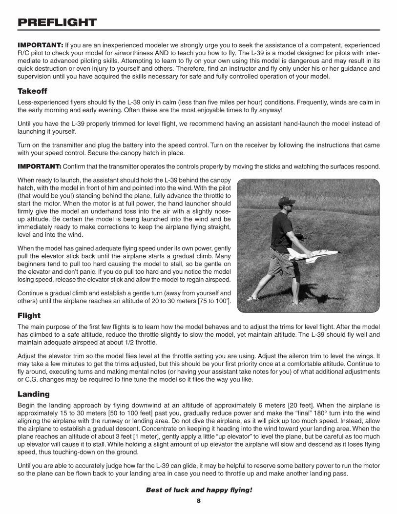
When ready to launch, the assistant should hold the L-39 behind the canopy hatch, with the model in front of him and pointed into the wind. With the pilot (that would be you!) standing behind the plane, fully advance the throttle to start the motor. When the motor is at full power, the hand launcher should firmly give the model an underhand toss into the air with a slightly nose-up attitude. Be certain the model is being launched into the wind and be immediately ready to make corrections to keep the airplane flying straight, level and into the wind.
When the model has gained adequate flying speed under its own power, gently pull the elevator stick back until the airplane starts a gradual climb. Many beginners tend to pull too hard causing the model to stall, so be gentle on the elevator and don’t panic. If you do pull too hard and you notice the model losing speed, release the elevator stick and allow the model to regain airspeed.
Continue a gradual climb and establish a gentle turn (away from yourself and others) until the airplane reaches an altitude of 20 to 30 meters [75 to 100'].
FlightThe main purpose of the first few flights is to learn how the model behaves and to adjust the trims for level flight. After the model has climbed to a safe altitude, reduce the throttle slightly to slow the model, yet maintain altitude. The L-39 should fly well and maintain adequate airspeed at about 1/2 throttle.
Adjust the elevator trim so the model flies level at the throttle setting you are using. Adjust the aileron trim to level the wings. It may take a few minutes to get the trims adjusted, but this should be your first priority once at a comfortable altitude. Continue to fly around, executing turns and making mental notes (or having your assistant take notes for you) of what additional adjustments or C.G. changes may be required to fine tune the model so it flies the way you like.
LandingBegin the landing approach by flying downwind at an altitude of approximately 6 meters [20 feet]. When the airplane is approximately 15 to 30 meters [50 to 100 feet] past you, gradually reduce power and make the “final” 180° turn into the wind aligning the airplane with the runway or landing area. Do not dive the airplane, as it will pick up too much speed. Instead, allow the airplane to establish a gradual descent. Concentrate on keeping it heading into the wind toward your landing area. When the plane reaches an altitude of about 3 feet [1 meter], gently apply a little “up elevator” to level the plane, but be careful as too much up elevator will cause it to stall. While holding a slight amount of up elevator the airplane will slow and descend as it loses flying speed, thus touching-down on the ground.
Until you are able to accurately judge how far the L-39 can glide, it may be helpful to reserve some battery power to run the motor so the plane can be flown back to your landing area in case you need to throttle up and make another landing pass.
Best of luck and happy fl ying!
9
SAFETY PRECAUTIONS
Protect Your Model, Yourself & Others…Follow These Important Safety Precautions 1. Your L-39 should not be considered a toy, but rather a sophisticated, working model that functions very much like a full-size
airplane. Because of its performance capabilities, the L-39, if not assembled and operated correctly, could possibly cause injury to yourself or spectators and damage to property.
2. You must assemble the model according to the instructions. Do not alter or modify the model, as doing so may result in an unsafe or unflyable model. In a few cases the instructions may differ slightly from the photos. In those instances the written instructions should be considered as correct.
3. You must take time to build straight, true and strong.
4. You must correctly install all R/C and other components so that the model operates correctly on the ground and in the air.
5. You must check the operation of the model before every flight to insure that all equipment is operating and that the model has remained structurally sound. Be sure to check pushrod connectors or servo arms often and replace them if they show any signs of wear or fatigue.
6. If you are not an experienced pilot or have not flown this type of model before, we recommend that you get the assistance of an experienced pilot in your R/C club for your first flights. If you’re not a member of a club, your local hobby shop has information about clubs in your area whose membership includes experienced pilots.
We, as the kit manufacturer, provide you with a top quality, thoroughly tested kit and instructions, but ultimately the quality and flyability of your finished model depends on how you build it; therefore, we cannot in any way guarantee the performance of your completed model, and no representations are expressed or implied as to the performance or safety of your completed model.
Remember: Take your time and follow the instructions to end up with a well-built model that is straight and true.
LITHIUM BATTERY PRECAUTIONSWARNING!! Read the entire instruction sheet included with the battery. Failure to follow all instructions could cause permanent damage to the battery and its surroundings, and cause bodily harm!
● ONLY use a LiPo approved charger. NEVER use a NiCd/NiMH peak charger!
● NEVER charge in excess of 4.20V per cell.● ONLY charge through the “charge” lead. NEVER charge
through the “discharge” lead.● NEVER charge at currents greater than 1C.● ALWAYS set charger’s output volts to match battery volts.● ALWAYS charge in a fireproof location.
● NEVER trickle charge.● NEVER allow battery temperature to exceed 150° F (65° C).● NEVER disassemble or modify pack wiring in any way or
puncture cells.● NEVER discharge below 2.5V per cell.● NEVER place on combustible materials or leave unattended
during charge or discharge.● ALWAYS KEEP OUT OF REACH OF CHILDREN.
ACADEMY OF MODEL AERONAUTICS If you are not already a member of the AMA, please join! The AMA is the governing body of model aviation and membership provides liability insurance coverage, protects modelers’ rights and interests and is required to fly at most R/C sites.
Tele. (800) 435-9262Fax (765) 741-0057modelaircraft.org
Academy of Model Aeronautics5151 East Memorial Drive
Muncie, IN 47302-9252
REPLACEMENT PARTS
Replacement parts may be purchased from your local hobby dealer or on-line. For assistance with defective or missing parts or purchasing replacement parts, contact Flyzone Product Support at the contact information on the front cover of this manual.
FLZA6535 Wing Set with TipsFLZA6536 Fuselage with HatchFLZA6537 Tail SetFLZA6538 Canopy HatchFLZA6539 Tip Tanks (2)
FLZA6540 Decal SheetFLZA6542 Display StandGPMG3910 HyperFlow Ducted Fan UnitGPMG3940 Ducted Fan Rotor BladeGPMG3941 Ducted Fan Misc. Parts
GPMG3942 Ducted Fan Outer DuctGPMG3943 Ducted Fan Adapter
10
DUCTED FAN BREAK-IN
Before you run the fan make sure that:
• An appropriate LiPo battery is being used.
• All the fan parts are properly attached to the fan and to the airframe.
• If any part of this fan should become damaged, replace all parts. Never attempt to repair damaged parts.
• Keep the fan away from objects as it will try to suck them in, which can cause damage to the fan and/or bodily injury.
• Always use eye protection when operating the fan unit.
• NEVER look into the fan as it is running.
• Ensure all persons in the immediate area are using eye protectionwhile the fan is in operation.
• NEVER point the fan in the direction of anyone.
• Make sure you inspect the fan and all its parts before each run.
• Never use motors larger than those recommended.
• Never run a fan that is damaged in any way.
• Never run the fan while holding it in your hands.
• NEVER run the fan above 50,000 rpm!
• Never run the fan rotor on any motor outside of the housing.
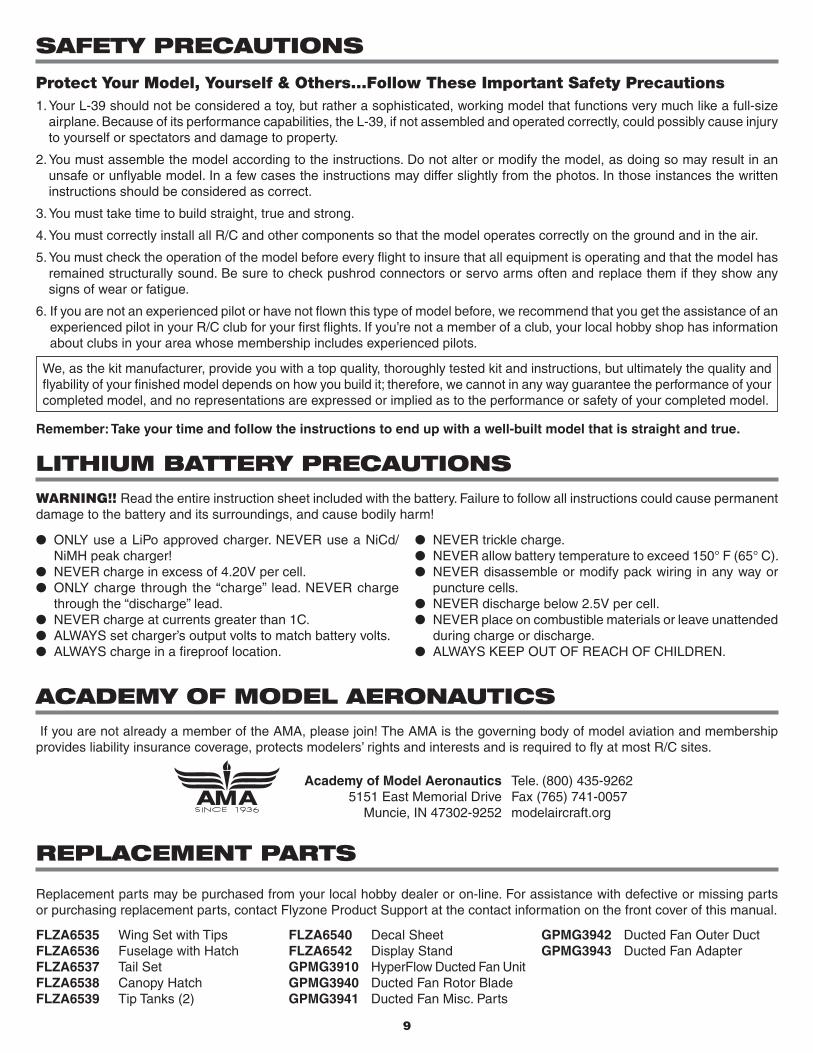
This is a device that runs at very high rpm and as such it needs to be handled carefully. There is a very short “break-in” period that needs to be followed to ensure that all parts fit well, everything is tight, and that no excessive vibration is present when running the fan. Also, the fan blades will expand as rpm are increased to the point of possibly touching the housing. This is expected and it is within the “break-in” procedures. The blades will get shortened slightly to fit the fan housing as they wear on the sides.
The procedure below must be followed carefully:1. If the fan is properly installed on an airframe and everything is ready to be tested, arm the speed controller and advance the throttle slowly to approximately 1/4 power for three minutes. Check for vibration and/or unusual noises. If there is vibration or unusual noise present during the test, do not proceed to step 2 until the problem is resolved. Inspect all moving parts, being sure that motor screws and the rotor adapter screws are tight. Confirm that the fan blades rotate smoothly within the housing and the rotor is not rubbing on the mounting plate (Be sure to unplug the battery from the ESC before handling the fan!).
2. If the fan operates smoothly, move the stick to 1/2 throttle and repeat the test as described in step 1.
3. Slowly advance the throttle to 3/4 power. When using high-power systems, the fan blades may rub a bit on the fan housing. You can see this by powering down the system and checking for marks or grooves in the housing. If this is the case, return to 1/2 throttle and cycle between 1/2 throttle and 3/4 throttle for three to four minutes. Doing so will adjust the length of the fan blades as they slowly wear on the fan housing.
4. Repeat the procedure described in step 3 between 3/4 throttle and full throttle.
5. Unplug the battery from the ESC and check the fan for rubbing, cracks, or missing parts.
If your fan appears damaged, vibrates excessively, or makes unexpected noises, please return it to Hobby Services for inspection.

11


![3. Rośliny lecznicze użytków zielonych. - Eko Sanokeko-sanok.com.pl/images/do_pobrania/Rosliny_uzytkow_zielonych... · Agropyron repens (L.) P. B EAUV . 3HU]Z áD FLZ\ Rodzina](https://img.pdfslide.net/doc/110x75/5c75bb1f09d3f231488bdbdf/3-rosliny-lecznicze-uzytkow-zielonych-eko-sanokeko-sanokcomplimagesdopobraniaroslinyuzytkowzielonych.jpg)
![Vectored Thrust Flying Wing - Hobbicomanuals.hobbico.com/flz/flza3612-14-manual.pdf · Vectored Thrust Flying Wing ... Weight: 29.6 – 31.3 oz [840 – 885 g] Wing Loading: 10.4](https://img.pdfslide.net/doc/110x75/5af1af897f8b9a8b4c8f147a/vectored-thrust-flying-wing-thrust-flying-wing-weight-296-313-oz-840.jpg)


![INSTRUCTION MANUAL - Hobbico, Inc. - largest U.S ...manuals.hobbico.com/flz/flza2102-manual.pdfFLZA2102 SPECIFICATIONS Wingspan: 15.9 in [404mm] Total Length: 15.7 in [399mm] Weight:](https://img.pdfslide.net/doc/110x75/5aa505477f8b9ae7438cd38c/instruction-manual-hobbico-inc-largest-us-specifications-wingspan-159.jpg)
![flz, phstg arXiv:1711.06025v2 [cs.CV] 27 Mar 2018 · 1Queen Mary University of London 2University of Oxford 3The University of Edinburgh floodsung@gmail.com t.xiang@qmul.ac.uk flz,](https://img.pdfslide.net/doc/110x75/5f6088302e3bf93cfb096040/flz-phstg-arxiv171106025v2-cscv-27-mar-2018-1queen-mary-university-of-london.jpg)