Embed Size (px)
Citation preview
Entire Contents © 2010 Hobbico®, Inc. HCAA2530 Mnl 2.0
READ THROUGH THIS MANUAL BEFORE STARTING CONSTRUCTION. IT CONTAINS IMPORTANTINSTRUCTIONS AND WARNINGS CONCERNING THE ASSEMBLY AND USE OF THIS MODEL.
WARRANTYHobbico guarantees this kit to be free from defects in both material and workmanship at the date of purchase. This warranty does not cover any component parts damaged by use or modification. In no case shall Hobbico’s liability exceed the original cost of the purchased kit. Further, Hobbico reserves the right to change or modify this warranty without notice.
In that Hobbico has no control over the final assembly or material used for final assembly, no liability shall be assumed nor accepted for any damage resulting from the use by the user of the final user-assembled product. By the act of using the user-assembled product, the user accepts all resulting liability.
If the buyer is not prepared to accept the liability associated with the use of this product, the buyer is advised to return
this kit immediately in new and unused condition to the place of purchase.
To make a warranty claim send the defective part or item to Hobby Services at the address below:
Hobby Services3002 N. Apollo Dr. Suite 1Champaign IL 61822 USA
Include a letter stating your name, return shipping address, as much contact information as possible (daytime telephone number, fax number, e-mail address), a detailed description of the problem and a photocopy of the purchase receipt. Upon receipt of the package the problem will be evaluated as quickly as possible.
™ Champaign, Illinois (217) 398-8970E-mail: [email protected]
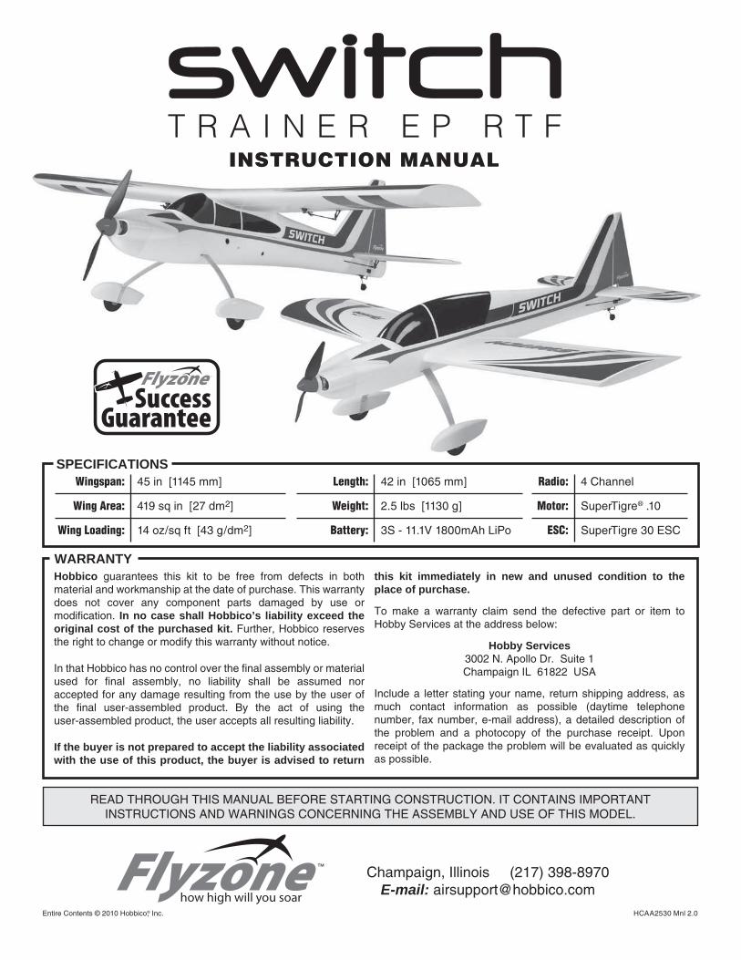
SPECIFICATIONSWingspan: 45 in [1145 mm]
Wing Area: 419 sq in [27 dm2]
Wing Loading: 14 oz/sq ft [43 g/dm2]
Length: 42 in [1065 mm]
Weight: 2.5 lbs [1130 g]
Battery: 3S - 11.1V 1800mAh LiPo
Radio: 4 Channel
Motor: SuperTigre® .10
ESC: SuperTigre 30 ESC
INSTRUCTION MANUALT R A I N E R E P R T F
2
TABLE OF CONTENTS
INTRODUCTION . . . . . . . . . . . . . . . . . . . . . . . . . . . . . . . . 2 AMA . . . . . . . . . . . . . . . . . . . . . . . . . . . . . . . . . . . . . . . 2IMPORTANT SAFETY PRECAUTIONS . . . . . . . . . . . . . . 2TOOLS REQUIRED . . . . . . . . . . . . . . . . . . . . . . . . . . . . . . 3IMPORTANT BUILDING NOTES. . . . . . . . . . . . . . . . . . . . 3KIT INSPECTION. . . . . . . . . . . . . . . . . . . . . . . . . . . . . . . . 3ORDERING REPLACEMENT PARTS . . . . . . . . . . . . . . . . 3SUCCESS GUARANTEE . . . . . . . . . . . . . . . . . . . . . . . . . 3KIT CONTENTS . . . . . . . . . . . . . . . . . . . . . . . . . . . . . . . . . 4ASSEMBLE THE MODEL . . . . . . . . . . . . . . . . . . . . . . . . . 5 Install the Landing Gear. . . . . . . . . . . . . . . . . . . . . . . . 5 Install the Tail Section . . . . . . . . . . . . . . . . . . . . . . . . . 6 Setting Up the High Wing Confi guration . . . . . . . . . . . 7 Install the Propeller . . . . . . . . . . . . . . . . . . . . . . . . . . . 8CHANGING TO THE LOW WING CONFIGURATION . . . . 8GET THE MODEL READY TO FLY . . . . . . . . . . . . . . . . . 10 Prepare the transmitter and LiPo Battery. . . . . . . . . . 10 Lithium Battery Handling & Usage. . . . . . . . . . . . . . . 10 Check the Control Directions . . . . . . . . . . . . . . . . . . . 10 SuperTigre ESC manual excerpts . . . . . . . . . . . . . . . 12 Check the Control Throws . . . . . . . . . . . . . . . . . . . . . 13 Balance the Model (C.G.). . . . . . . . . . . . . . . . . . . . . . 13 Balance the Model Laterally. . . . . . . . . . . . . . . . . . . . 14PREFLIGHT . . . . . . . . . . . . . . . . . . . . . . . . . . . . . . . . . . . 14 Identify Your Model . . . . . . . . . . . . . . . . . . . . . . . . . . . 14 Balance Propellers. . . . . . . . . . . . . . . . . . . . . . . . . . . 14 Range Check . . . . . . . . . . . . . . . . . . . . . . . . . . . . . . . 14MOTOR SAFETY PRECAUTIONS . . . . . . . . . . . . . . . . . 14AMA SAFETY CODE (excerpts). . . . . . . . . . . . . . . . . . . 14 General . . . . . . . . . . . . . . . . . . . . . . . . . . . . . . . . . . . 14 Radio Control . . . . . . . . . . . . . . . . . . . . . . . . . . . . . . . 15CHECK LIST . . . . . . . . . . . . . . . . . . . . . . . . . . . . . . . . . . 15FLYING. . . . . . . . . . . . . . . . . . . . . . . . . . . . . . . . . . . . . . . 15 Takeoff . . . . . . . . . . . . . . . . . . . . . . . . . . . . . . . . . . . . 15 Flight . . . . . . . . . . . . . . . . . . . . . . . . . . . . . . . . . . . . . 16 Landing . . . . . . . . . . . . . . . . . . . . . . . . . . . . . . . . . . . 16
INTRODUCTION
Thank you for purchasing the Switch Trainer EP! The Switch Trainer is a revolutionary new concept in R/C airplane fl ight. Learn to fl y with the Switch Trainer high wing confi guration, then move the wings to the low wing confi guration for exciting aerobatic fl ight, with the same plane! In addition to getting two airplanes in one, the model is made from durable AeroCell™ foam. Should the model become damaged, it is easily repairable with epoxy or regular CA glue.
For the latest technical updates or manual corrections to the Switch Trainer EP visit the Hobbico web site at www.hobbico.com. Open the “Airplanes” link, then select the Switch Trainer EP. If there is new technical information or changes to this model a “tech notice” box will appear in the upper left corner of the page.
AMA
We urge you to join the AMA (Academy of Model Aeronautics) and a local R/C club. The AMA is the governing body of model aviation and membership is required to fl y at AMA clubs. Though joining the AMA provides many benefi ts, one of the primary reasons to join is liability protection. Coverage is not limited to fl ying at contests or on the club fi eld. It even applies to fl ying at public demonstrations and air shows. Failure to comply with the Safety Code (excerpts printed in the back of the manual) may endanger insurance coverage. Additionally, training programs and instructors are available at AMA club sites to help you get started the right way. There are over 2,500 AMA chartered clubs across the country. Contact the AMA at the address or toll-free phone number below:
Academy of Model Aeronautics5151 East Memorial DriveMuncie, IN 47302-9252
Ph. (800) 435-9262Fax (765) 741-0057
Or via the Internet at:http://www.modelaircraft.orghttp://www.modelaircraft.org/parkfl yer.aspx
IMPORTANT!!! Two of the most important things you can do to preserve the radio controlled aircraft hobby are to avoid fl ying near full-scale aircraft and avoid fl ying near or over groups of people.
PROTECT YOUR MODEL, YOURSELF & OTHERS… FOLLOW THESE
IMPORTANT SAFETY PRECAUTIONS
1. Your Switch Trainer EP should not be considered a toy, but rather a sophisticated, working model that functions very much like a full-size airplane. Because of its performance capabilities, the Switch Trainer EP, if not assembled and operated correctly, could possibly cause injury to yourself or spectators and damage to property.
2. You must assemble the model according to the instructions. Do not alter or modify the model, as doing so may result in an unsafe or unfl yable model. In a few cases the instructions may differ slightly from the photos. In those instances the written instructions should be considered as correct.
3. You must take time to build straight, true and strong.
4. You must use an R/C radio system that is in fi rst-class condition, and a correctly sized motor and components throughout the building process.
5. You must correctly install all R/C and other components so that the model operates correctly on the ground and in the air.

3
6. You must check the operation of the model before every fl ight to ensure that all equipment is operating and that the model has remained structurally sound. Be sure to check clevises or other connectors often and replace them if they show any signs of wear or fatigue.
7. If you are not an experienced pilot or have not fl own this type of model before, we recommend that you get the assistance of an experienced pilot in your R/C club for your fi rst fl ights. If you’re not a member of a club, your local hobby shop has information about clubs in your area whose membership includes experienced pilots.
8. While this kit has been fl ight tested to exceed normal use, if the plane will be used for extremely high stress fl ying, such as racing, or if a motor larger than one in the recommended range is used, the modeler is responsible for taking steps to reinforce the high stress points and/or substituting hardware more suitable for the increased stress.
We, as the kit manufacturer, provide you with a top quality, thoroughly tested kit and instructions, but ultimately the quality and fl yability of your fi nished model depends on how you build it; therefore, we cannot in any way guarantee the performance of your completed model, and no representations are expressed or implied as to the performance or safety of your completed model.
Remember: Take your time and follow the instructions to end up with a well-built model that is straight and true.
TOOLS REQUIRED
The Switch Trainer EP RTF requires only AA batteries and common household tools to fi nish assembly:
❍ (4) AA batteries (FUGP7300) ❍ #2 Phillips screw driver ❍ Slotted screw driver
IMPORTANT BUILDING NOTES
● Photos and sketches are placed before the step they refer to. Frequently you can study photos in following steps to get another view of the same parts.
● The stabilizer and wing incidences and engine thrust angles have been factory-built into this model. However, some technically-minded modelers may wish to check these measurements anyway. To view this information visit the web site at www.hobbico.com and click on “Technical Data.” Due to manufacturing tolerances which will have little or no effect on the way your model will fl y, please expect slight deviations between your model and the published values.
KIT INSPECTION
Before starting to build, take an inventory of this kit to make sure it is complete, and inspect the parts to make sure they are of acceptable quality. If any parts are missing or are not of acceptable quality, or if you need assistance with assembly,
contact Product Support. When reporting defective or missing parts, use the part names exactly as they are written in the Kit Contents list on this page.
Hobbico Product Support Ph: (217) 398-8970 ext. 53002 N Apollo Drive Suite 1 Fax: (217) 398-7721Champaign, IL 61822
E-mail: [email protected]
ORDERING REPLACEMENT PARTS
Replacement parts for the Hobbico Switch Trainer EP are available using the order numbers in the Replacement Parts List that follows. The fastest, most economical service can be provided by your hobby dealer or mail-order company. Parts may also be ordered directly from Hobby Services, but full retail prices and shipping and handling charges will apply. Illinois and Nevada residents will also be charged sales tax.
To locate a hobby dealer, visit the Hobbico web site at www.hobbico.com. Choose “Where to Buy” at the bottom of the menu on the left side of the page. Follow the instructions provided on the page to locate a U.S., Canadian or International dealer.
Parts may also be ordered directly from Hobby Services by calling (217) 398-0007, or via facsimile at (217) 398-7721, but full retail prices and shipping and handling charges will apply. Illinois and Nevada residents will also be charged sales tax. If ordering via fax, include a Visa® or MasterCard® number and expiration date for payment.
Mail parts orders Hobby Services and payments by 3002 N Apollo Drive, Suite 1 personal check to: Champaign IL 61822
Be certain to specify the order number exactly as listed in the Replacement Parts List. Payment by credit card or personal check only; no C.O.D.
If additional assistance is required for any reason contact Product Support by e-mail at [email protected], or by telephone at (217) 398-8970.
SUCCESS GUARANTEE
We are so confi dent that the Switch is the best ready-to-fl y trainer available that we make this guarantee: You will successfully learn to fl y with the Switch or we will replace it with your choice of any Flyzone trainer of up to equal value. All we ask is that you train with the Switch in its high-wing confi guration, under the supervision of a qualifi ed, club-designated instructor; follow normal safety precautions; fl y at an AMA-chartered club; and construct the kit as outlined in the included instruction manual.
If you crash your Switch before completing your fl ight training despite following the conditions outlined above, contact Hobby Services, Monday through Friday, 9AM to 5PM Central time, to request a replacement. You must verify that all terms and conditions of the fl ight guarantee have been met, as follows:
4
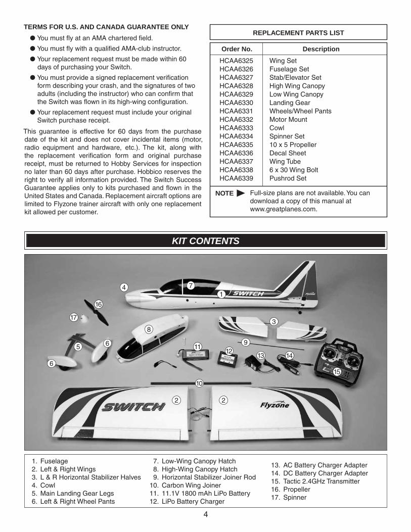
KIT CONTENTS
1. Fuselage 2. Left & Right Wings 3. L & R Horizontal Stabilizer Halves 4. Cowl 5. Main Landing Gear Legs 6. Left & Right Wheel Pants
7. Low-Wing Canopy Hatch 8. High-Wing Canopy Hatch 9. Horizontal Stabilizer Joiner Rod 10. Carbon Wing Joiner 11. 11.1V 1800 mAh LiPo Battery 12. LiPo Battery Charger
13. AC Battery Charger Adapter 14. DC Battery Charger Adapter 15. Tactic 2.4GHz Transmitter 16. Propeller 17. Spinner
1
2 2
3
4
5
6
6
7
8
9
10
1112
13 14
15
16
17
TERMS FOR U.S. AND CANADA GUARANTEE ONLY
● You must fl y at an AMA chartered fi eld.
● You must fl y with a qualifi ed AMA-club instructor.
● Your replacement request must be made within 60 days of purchasing your Switch.
● You must provide a signed replacement verifi cation form describing your crash, and the signatures of two adults (including the instructor) who can confi rm that the Switch was fl own in its high-wing confi guration.
● Your replacement request must include your original Switch purchase receipt.
This guarantee is effective for 60 days from the purchase date of the kit and does not cover incidental items (motor, radio equipment and hardware, etc.). The kit, along with the replacement verifi cation form and original purchase receipt, must be returned to Hobby Services for inspection no later than 60 days after purchase. Hobbico reserves the right to verify all information provided. The Switch Success Guarantee applies only to kits purchased and fl own in the United States and Canada. Replacement aircraft options are limited to Flyzone trainer aircraft with only one replacement kit allowed per customer.
Order No. Description
REPLACEMENT PARTS LIST
Wing SetFuselage SetStab/Elevator SetHigh Wing CanopyLow Wing CanopyLanding GearWheels/Wheel PantsMotor MountCowlSpinner Set10 x 5 PropellerDecal SheetWing Tube6 x 30 Wing BoltPushrod Set
HCAA6325HCAA6326HCAA6327HCAA6328HCAA6329HCAA6330HCAA6331HCAA6332HCAA6333HCAA6334HCAA6335HCAA6336HCAA6337HCAA6338HCAA6339
NOTE Full-size plans are not available. You can download a copy of this manual at www.greatplanes.com.
5
ASSEMBLE THE MODEL
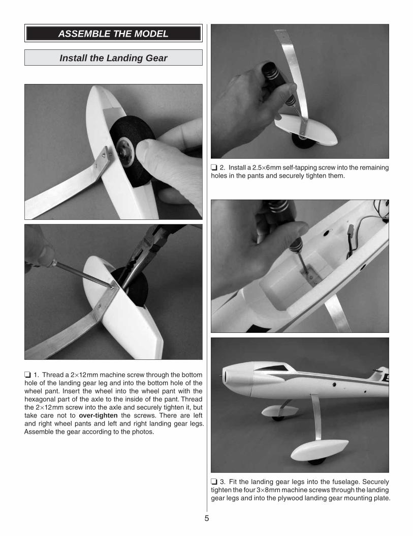
Install the Landing Gear
❏ 1. Thread a 2×12mm machine screw through the bottom hole of the landing gear leg and into the bottom hole of the wheel pant. Insert the wheel into the wheel pant with the hexagonal part of the axle to the inside of the pant. Thread the 2×12mm screw into the axle and securely tighten it, but take care not to over-tighten the screws. There are left and right wheel pants and left and right landing gear legs. Assemble the gear according to the photos.
❏ 2. Install a 2.5×6mm self-tapping screw into the remaining holes in the pants and securely tighten them.
❏ 3. Fit the landing gear legs into the fuselage. Securely tighten the four 3×8mm machine screws through the landing gear legs and into the plywood landing gear mounting plate.
6
Install the Tail Section
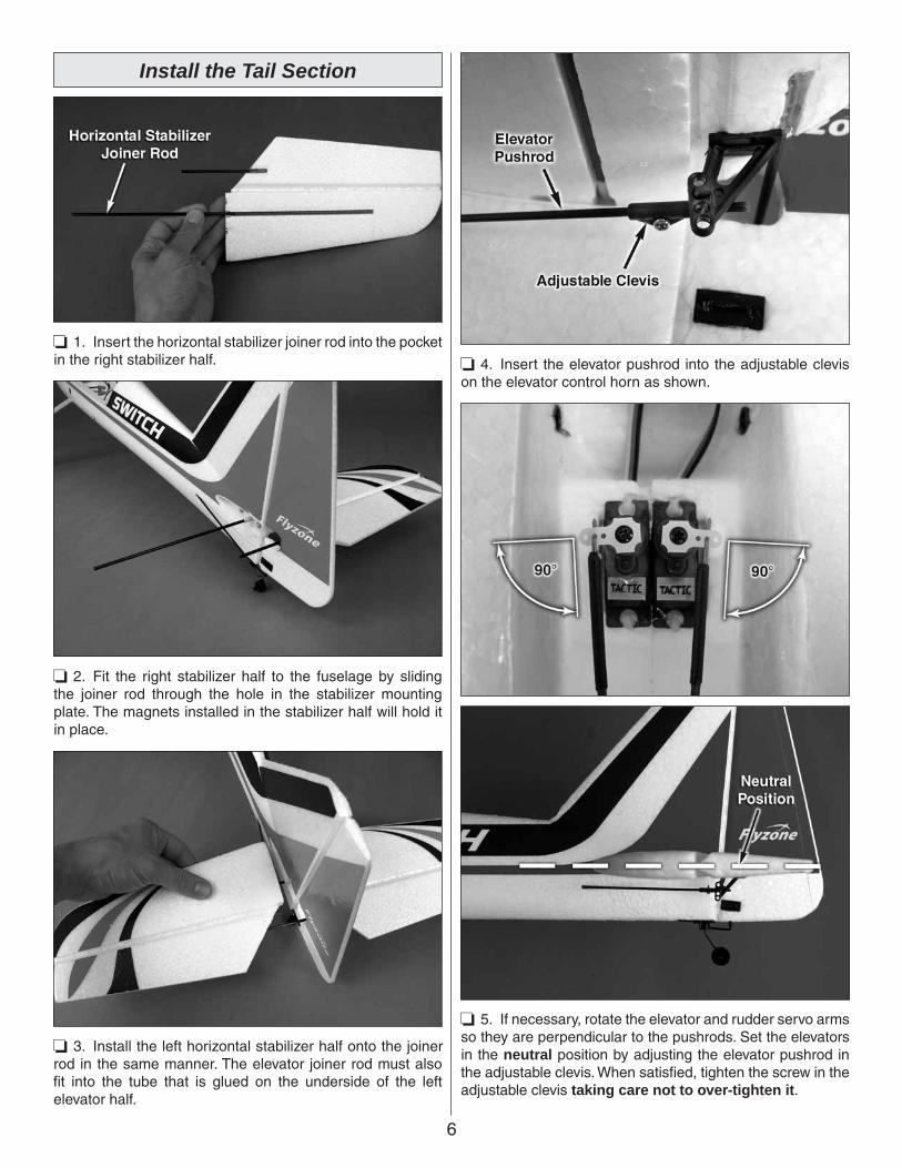
❏ 1. Insert the horizontal stabilizer joiner rod into the pocket in the right stabilizer half.
❏ 2. Fit the right stabilizer half to the fuselage by sliding the joiner rod through the hole in the stabilizer mounting plate. The magnets installed in the stabilizer half will hold it in place.
❏ 3. Install the left horizontal stabilizer half onto the joiner rod in the same manner. The elevator joiner rod must also fi t into the tube that is glued on the underside of the left elevator half.
❏ 4. Insert the elevator pushrod into the adjustable clevis on the elevator control horn as shown.
❏ 5. If necessary, rotate the elevator and rudder servo arms so they are perpendicular to the pushrods. Set the elevators in the neutral position by adjusting the elevator pushrod in the adjustable clevis. When satisfi ed, tighten the screw in the adjustable clevis taking care not to over-tighten it.
7
❏ 6. Insert the rudder pushrod into the adjustable clevis on the rudder control horn and set the rudder to the neutral position in the same manner as you did the elevators. Tighten the screw in the adjustable clevis. Do not over-tighten.
Setting Up the High Wing Confi guration
We recommend fl ying the Switch Trainer EP fi rst in the high wing confi guration. The high wing position will provide some self-recovery characteristics which will aid the beginning pilot with straight and level fl ight. It will also make the orientation of the airplane more visible at high altitudes.
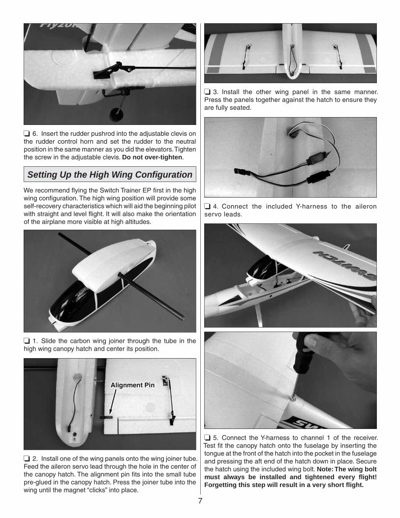
❏ 1. Slide the carbon wing joiner through the tube in the high wing canopy hatch and center its position.
❏ 2. Install one of the wing panels onto the wing joiner tube. Feed the aileron servo lead through the hole in the center of the canopy hatch. The alignment pin fi ts into the small tube pre-glued in the canopy hatch. Press the joiner tube into the wing until the magnet “clicks” into place.
❏ 3. Install the other wing panel in the same manner. Press the panels together against the hatch to ensure they are fully seated.
❏ 4. Connect the included Y-harness to the aileron servo leads.
❏ 5. Connect the Y-harness to channel 1 of the receiver. Test fi t the canopy hatch onto the fuselage by inserting the tongue at the front of the hatch into the pocket in the fuselage and pressing the aft end of the hatch down in place. Secure the hatch using the included wing bolt. Note: The wing bolt must always be installed and tightened every fl ight! Forgetting this step will result in a very short fl ight.
8
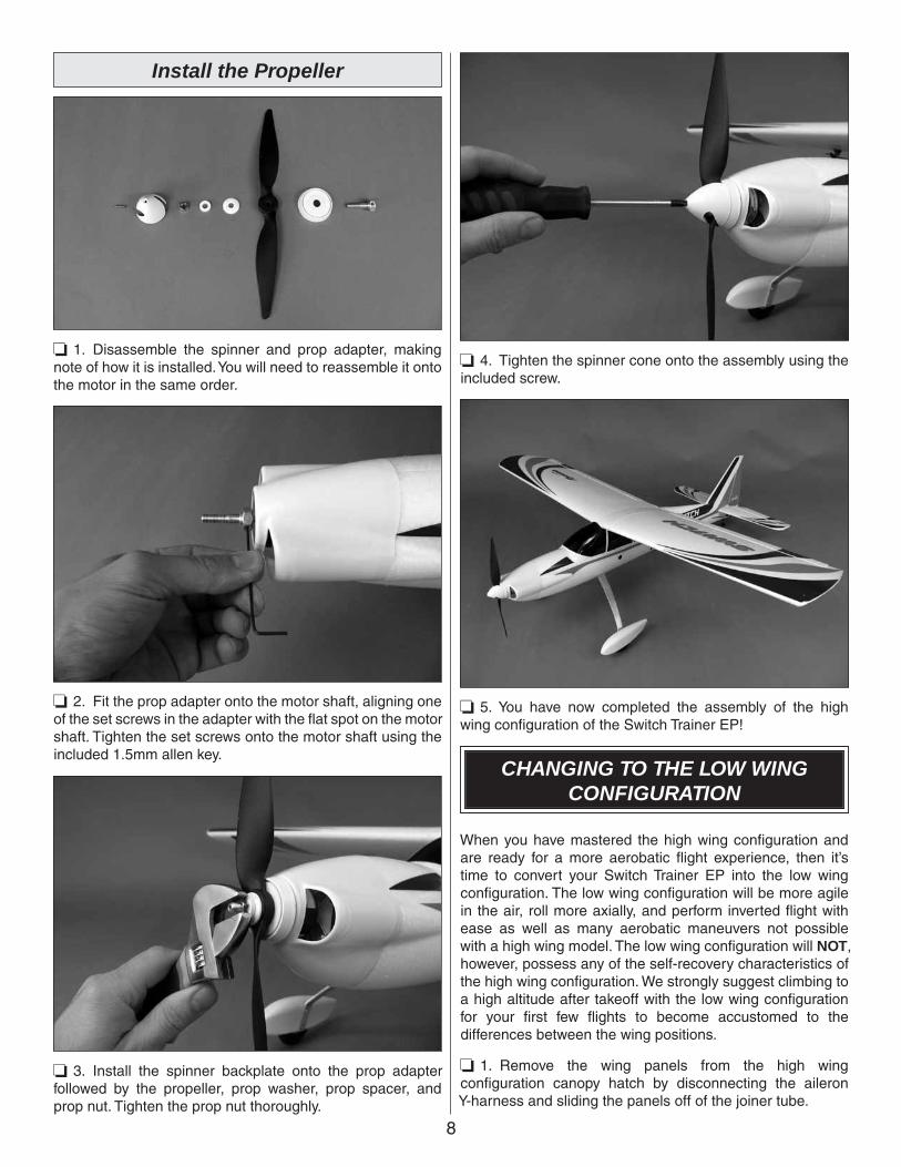
Install the Propeller
❏ 1. Disassemble the spinner and prop adapter, making note of how it is installed. You will need to reassemble it onto the motor in the same order.
❏ 2. Fit the prop adapter onto the motor shaft, aligning one of the set screws in the adapter with the fl at spot on the motor shaft. Tighten the set screws onto the motor shaft using the included 1.5mm allen key.
❏ 3. Install the spinner backplate onto the prop adapter followed by the propeller, prop washer, prop spacer, and prop nut. Tighten the prop nut thoroughly.
❏ 4. Tighten the spinner cone onto the assembly using the included screw.
❏ 5. You have now completed the assembly of the high wing confi guration of the Switch Trainer EP!
CHANGING TO THE LOW WINGCONFIGURATION
When you have mastered the high wing confi guration and are ready for a more aerobatic fl ight experience, then it’s time to convert your Switch Trainer EP into the low wing confi guration. The low wing confi guration will be more agile in the air, roll more axially, and perform inverted fl ight with ease as well as many aerobatic maneuvers not possible with a high wing model. The low wing confi guration will NOT, however, possess any of the self-recovery characteristics of the high wing confi guration. We strongly suggest climbing to a high altitude after takeoff with the low wing confi guration for your fi rst few fl ights to become accustomed to the differences between the wing positions.
❏ 1. Remove the wing panels from the high wing confi guration canopy hatch by disconnecting the aileron Y-harness and sliding the panels off of the joiner tube.
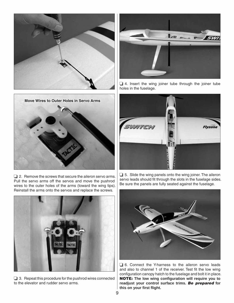
9
❏ 2. Remove the screws that secure the aileron servo arms. Pull the servo arms off the servos and move the pushrod wires to the outer holes of the arms (toward the wing tips). Reinstall the arms onto the servos and replace the screws.
❏ 3. Repeat this procedure for the pushrod wires connected to the elevator and rudder servo arms.
❏ 4. Insert the wing joiner tube through the joiner tube holes in the fuselage.
❏ 5. Slide the wing panels onto the wing joiner. The aileron servo leads should fi t through the slots in the fuselage sides. Be sure the panels are fully seated against the fuselage.
❏ 6. Connect the Y-harness to the aileron servo leads and also to channel 1 of the receiver. Test fi t the low wing confi guration canopy hatch to the fuselage and bolt it in place. NOTE: The low wing confi guration will require you to readjust your control surface trims. Be prepared for this on your fi rst fl ight.
10
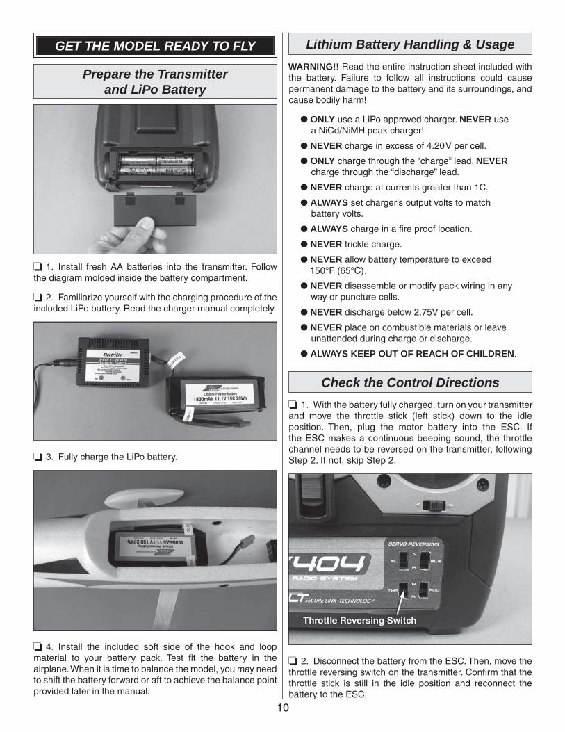
GET THE MODEL READY TO FLY
Prepare the Transmitterand LiPo Battery
❏ 1. Install fresh AA batteries into the transmitter. Follow the diagram molded inside the battery compartment.
❏ 2. Familiarize yourself with the charging procedure of the included LiPo battery. Read the charger manual completely.
❏ 3. Fully charge the LiPo battery.
❏ 4. Install the included soft side of the hook and loop material to your battery pack. Test fi t the battery in the airplane. When it is time to balance the model, you may need to shift the battery forward or aft to achieve the balance point provided later in the manual.
Lithium Battery Handling & Usage
WARNING!! Read the entire instruction sheet included with the battery. Failure to follow all instructions could cause permanent damage to the battery and its surroundings, and cause bodily harm!
● ONLY use a LiPo approved charger. NEVER use a NiCd/NiMH peak charger!
● NEVER charge in excess of 4.20V per cell.
● ONLY charge through the “charge” lead. NEVER charge through the “discharge” lead.
● NEVER charge at currents greater than 1C.
● ALWAYS set charger’s output volts to match battery volts.
● ALWAYS charge in a fi re proof location.
● NEVER trickle charge.
● NEVER allow battery temperature to exceed 150°F (65°C).
● NEVER disassemble or modify pack wiring in any way or puncture cells.
● NEVER discharge below 2.75V per cell.
● NEVER place on combustible materials or leave unattended during charge or discharge.
● ALWAYS KEEP OUT OF REACH OF CHILDREN.
Check the Control Directions
❏ 1. With the battery fully charged, turn on your transmitter and move the throttle stick (left stick) down to the idle position. Then, plug the motor battery into the ESC. If the ESC makes a continuous beeping sound, the throttle channel needs to be reversed on the transmitter, following Step 2. If not, skip Step 2.
❏ 2. Disconnect the battery from the ESC. Then, move the throttle reversing switch on the transmitter. Confi rm that the throttle stick is still in the idle position and reconnect the battery to the ESC.
11
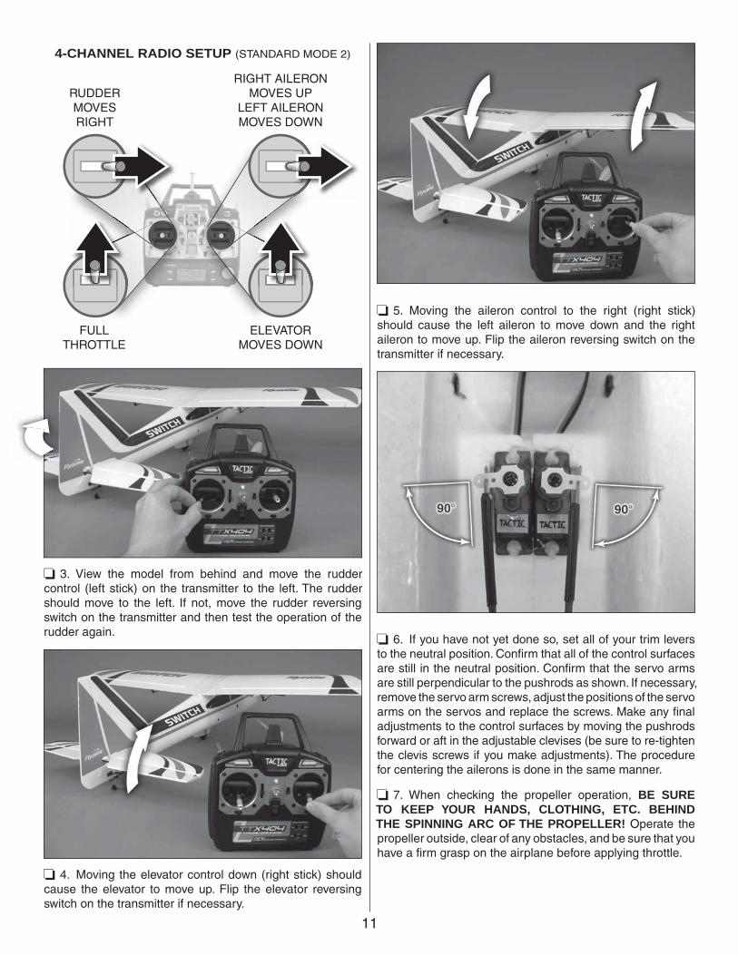
FULLTHROTTLE
RUDDERMOVESRIGHT
ELEVATORMOVES DOWN
RIGHT AILERONMOVES UP
LEFT AILERONMOVES DOWN
4-CHANNEL RADIO SETUP (STANDARD MODE 2)
❏ 3. View the model from behind and move the rudder control (left stick) on the transmitter to the left. The rudder should move to the left. If not, move the rudder reversing switch on the transmitter and then test the operation of the rudder again.
❏ 4. Moving the elevator control down (right stick) should cause the elevator to move up. Flip the elevator reversing switch on the transmitter if necessary.
❏ 5. Moving the aileron control to the right (right stick) should cause the left aileron to move down and the right aileron to move up. Flip the aileron reversing switch on the transmitter if necessary.
❏ 6. If you have not yet done so, set all of your trim levers to the neutral position. Confi rm that all of the control surfaces are still in the neutral position. Confi rm that the servo arms are still perpendicular to the pushrods as shown. If necessary, remove the servo arm screws, adjust the positions of the servo arms on the servos and replace the screws. Make any fi nal adjustments to the control surfaces by moving the pushrods forward or aft in the adjustable clevises (be sure to re-tighten the clevis screws if you make adjustments). The procedure for centering the ailerons is done in the same manner.
❏ 7. When checking the propeller operation, BE SURE TO KEEP YOUR HANDS, CLOTHING, ETC. BEHIND THE SPINNING ARC OF THE PROPELLER! Operate the propeller outside, clear of any obstacles, and be sure that you have a fi rm grasp on the airplane before applying throttle.
12
The following are excerpts from the SuperTigre® 30A ESC manual that are necessary for operating the ESC. The complete manual can be viewed online at http://manuals.hobbico.com/sup/supm1020-1030-manual.pdf
NECESSARY TRANSMITTER SETTINGS
For proper ESC operation, it’s very important to set the transmitter’s throttle channel adjustments, as follows:
1. Set the throttle channel’s travel adjustment (ATV,EPA or ATL) to 100%.
2. Set the throttle trim and sub-trim to neutral or zero.
3. Set the throttle channel’s reversing switch to reverse on Futaba® transmitters. Other transmitters might require you to set the throttle reversing switch to normal.
CONNECTING THE BATTERY
IMPORTANT! REMOVE THE PROPELLER FROM THE MOTOR BEFORE CONNECTING THE BATTERY!
WARNING! Never accidentally short together the positive (+) and negative (-) battery connections! Doing so will result in permanent damage.
SuperTigre ESCs have a unique “ST” type polarized battery connector as shown here, which is custom-matched to the connector on SuperTigre LiPo batteries. These plugs are polarized and cannot accidentally be connected backwards. SuperTigre offers several sizes of LiPo batteries to suit various needs, which can be found at most hobby retailers:
SUPP1010 640mAh 11.1V LiPo
SUPP1020 910mAh 11.1V LiPo
SUPP1030 1250mAh 11.1V LiPo
SUPP1050 1500mAh 11.1V LiPo
SUPP1060 1800mAh 11.1V LiPo (*Used on this plane)
SUPP1070 2100mAh 11.1V LiPo
To adapt your SuperTigre ESC to batteries having different types of connectors, see your local retailer for these SuperTigre adapters to meet your needs:
SUPM0040 Adapter - Deans® Ultra® Male to SuperTigre ESC
SUPM0050 Adapter - Deans Micro to SuperTigre ESC
SUPM0060 Adapter - Standard Female to SuperTigre ESC
IMPORTANT! The battery must be fully charged BEFORE being connected to the ESC. The ESC will then
automatically set the low voltage cut-off point based on the INITIAL voltage of the battery multiplied by 0.67. So, if the battery is NOT fully charged when connected to the ESC, the ESC may set a low voltage cut-off that is too low, and may not be good for your battery. Make sure the battery is fully charged prior to every use.
LOW VOLTAGE CUT-OFF: SuperTigre ESCs include a low-voltage cut-off feature that stops motor rotation if the battery’s voltage drops too low. This protects the battery from damage due to under-voltage conditions. When the low voltage cut-off stops motor rotation it will still supply power to the receiver and all control surfaces except throttle, so you can maintain control of the aircraft.
SETTING UP THE BRAKE FUNCTION
SuperTigre ESCs include an adjustable brake function. To keep the factory default brake setting of “off”, skip to the next section. To turn the brake “on”:
1. With the transmitter power turned off, move the throttle stick to full position.
2. Turn on the transmitter and connect the fully charged battery to the ESC.
3. After 5 seconds the motor will beep twice.4. Move the throttle stick to the minimum position. The
motor will beep twice.5. Again move the throttle stick to full power. The motor
will beep twice to confi rm the brake is now “on”.6. Move the throttle stick back to “off”. The motor will
now beep four times indicating the motor is “armed”, and the motor WILL ROTATE anytime the throttle stick is advanced.
Once the brake is set, it does not require resetting after the ESC has been switched off.
If the brake had previously been turned on, but you wish to turn the brake off, repeat the above process. This time the motor will only beep once with each stick movement, but will beep four times again at the end to indicate the ESC is armed.
ARMING THE ESC & SAFE-START FUNCTION
If ready to apply power to the motor:
1. Turn the transmitter’s power on.
2. Move the throttle stick to the minimum or brake position (towards you).
3. Connect a fully charged battery to the ESC. The motor will beep to indicate the brake setting (once for off, twice for on).
4. Move the throttle stick to full. The motor will again beep once or twice to indicate the brake setting.
5. Move the throttle stick to “off” or “brake” and the motor will beep four times. The ESC is now “armed”, and the motor WILL ROTATE anytime the throttle stick is advanced.
13
If the ESC does not operate properly or makes a low pitched beeping sound following the above set-up procedure, disconnect the battery from the ESC, reverse the throttle setting on the transmitter and repeat the ESC set-up.
SAFE-START: As a safety precaution to prevent the motor from rotating when the battery is fi rst connected, you must “arm” the ESC every time you connect the battery. The propeller will NOT rotate until the ESC is armed. To arm the ESC, move the throttle stick to full position, then back to “off” (or “brake”). Now the motor will rotate anytime the throttle stick is advanced away from the “off” position! Care must be exercised when near the model’s propeller!
Check the Control Throws
The Switch Trainer EP RTF is setup from the factory with the recommended control throws for the high wing confi guration. If at any time you wish to return to the default control throws, or if you simply want to confi rm the throws, use the following measurements:
NOTE: The throws are measured at the widest part of the elevators, rudder and ailerons.
These are the recommended control surface throws:
ELEVATORUp & Down 1/2" [13mm] 16 deg
RUDDERRight & Left 3/4" [19mm] 12 deg
AILERONSUp & Down 1/4" [6mm] 9 deg
ELEVATORUp & Down 5/8" [16mm] 20 deg
RUDDERRight & Left 1" [25mm] 17 deg
AILERONSUp & Down
HIG
H W
ING
CO
NF
IGU
RA
TIO
NL
OW
WIN
GC
ON
FIG
UR
AT
ION
5/16" [8mm] 11 deg
Balance the Model (C.G.)
More than any other factor, the C.G. (center of gravity/balance point) can have the greatest effect on how a model fl ies and could determine whether or not your fi rst fl ight will be successful. If you value your model and wish to enjoy it for many fl ights, DO NOT OVERLOOK THIS IMPORTANT PROCEDURE. A model that is not properly balanced may be unstable and possibly unfl yable.
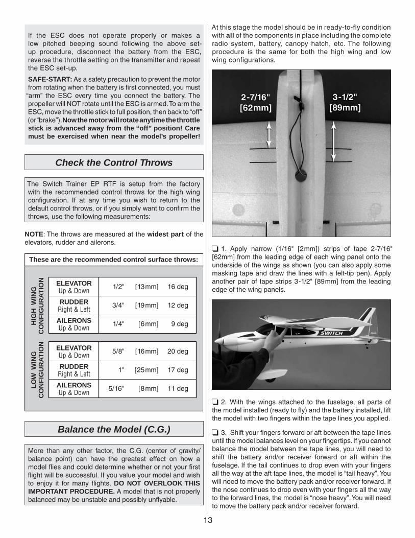
At this stage the model should be in ready-to-fly condition with all of the components in place including the complete radio system, battery, canopy hatch, etc. The following procedure is the same for both the high wing and low wing configurations.
❏ 1. Apply narrow (1/16" [2mm]) strips of tape 2-7/16" [62mm] from the leading edge of each wing panel onto the underside of the wings as shown (you can also apply some masking tape and draw the lines with a felt-tip pen). Apply another pair of tape strips 3-1/2" [89mm] from the leading edge of the wing panels.
❏ 2. With the wings attached to the fuselage, all parts of the model installed (ready to fl y) and the battery installed, lift the model with two fi ngers within the tape lines you applied.
❏ 3. Shift your fi ngers forward or aft between the tape lines until the model balances level on your fi ngertips. If you cannot balance the model between the tape lines, you will need to shift the battery and/or receiver forward or aft within the fuselage. If the tail continues to drop even with your fi ngers all the way at the aft tape lines, the model is “tail heavy”. You will need to move the battery pack and/or receiver forward. If the nose continues to drop even with your fi ngers all the way to the forward lines, the model is “nose heavy”. You will need to move the battery pack and/or receiver forward.
14
❏ 4. If you found it necessary to move the battery or receiver, recheck the C.G. to confi rm the plane now balances between the tape lines. Do not fl y a plane that has not been properly balanced!
Balance the Model Laterally
❏ 1. With the wing level, have an assistant help you lift the model by the engine propeller shaft and the bottom of the fuse under the TE of the fi n. Do this several times.
❏ 2. If one wing always drops when you lift the model, it means that side is heavy. Balance the airplane by adding weight to the other wing tip. Stick-on lead weight can be purchased from your hobby supplier (GPMQ4485). An airplane that has been laterally balanced will track better in loops and other maneuvers.
PREFLIGHT
Identify Your Model
No matter if you fly at an AMA sanctioned R/C club site or if you fly somewhere on your own, you should always have your name, address, telephone number and AMA number on or inside your model. It is required at all AMA R/C club flying sites and AMA sanctioned flying events. Fill out the identification tag on page 16 and place it on or inside your model.
Balance Propellers
Carefully balance your propeller and spare propellers before you fl y. An unbalanced prop can be the single most signifi cant cause of vibration that can damage your model. Not only will motor mounting screws and bolts loosen, possibly with disastrous effect, but vibration may also damage your receiver and battery.
We use a Top Flite® Precision Magnetic Prop Balancer (TOPQ5700) in the workshop and keep a Great Planes® Fingertip Prop Balancer (GPMQ5000) in our fl ight box.
Range Check
The “range” is the safe operating distance from the transmitter to the receiver, and should be as far as you can clearly see the model. With the assistance of another person, place the aircraft on the ground and walk 100 feet (30m) away from the model. With the transmitter pointed directly at the model, operate the transmitter’s controls, and ensure the movement of all surfaces is according to the movement of the transmitter.
MOTOR SAFETY PRECAUTIONS
Failure to follow these safety precautions may result in severe injury to yourself and others.
● Get help from an experienced pilot when learning to operate motors.
● Use safety glasses when starting or running motors.
● Do not run the motor in an area of loose gravel or sand; the propeller may throw such material in your face or eyes.
● Keep your face and body as well as all spectators away from the plane of rotation of the propeller as you run the motor.
● Keep these items away from the prop: loose clothing, shirt sleeves, ties, scarfs, long hair or loose objects such as pencils or screwdrivers that may fall out of shirt or jacket pockets into the prop.
● The motor gets hot! Do not touch it during or right after operation.
● Do not throw anything into the propeller of a rotating motor.
AMA SAFETY CODE (EXCERPTS)
Read and abide by the following excerpts from the Academy of Model Aeronautics Safety Code. For the complete Safety Code refer to Model Aviation magazine, the AMA web site or the Code that came with your AMA license.
General
1) I will not fl y my model aircraft in sanctioned events, air shows, or model fl ying demonstrations until it has been proven to be airworthy by having been previously, successfully fl ight tested.
2) I will not fl y my model aircraft higher than approximately 400 feet [120m] within 3 miles [4.8km] of an airport without notifying the airport operator. I will give right-of-way and avoid fl ying in the proximity of full-scale aircraft. Where necessary, an observer shall be utilized to supervise fl ying to avoid having models fl y in the proximity of full-scale aircraft.
15
3) Where established, I will abide by the safety rules for the fl ying site I use, and I will not willfully and deliberately fl y my models in a careless, reckless and/or dangerous manner.
5) I will not fl y my model unless it is identifi ed with my name and address or AMA number, on or in the model. Note: This does not apply to models while being fl own indoors.
7) I will not operate models with pyrotechnics (any device that explodes, burns, or propels a projectile of any kind).
Radio Control
1) I will have completed a successful radio equipment ground check before the fi rst fl ight of a new or repaired model.
2) I will not fl y my model aircraft in the presence of spectators until I become a qualifi ed fl ier, unless assisted by an experienced helper.
3) At all fl ying sites a straight or curved line(s) must be established in front of which all fl ying takes place with the other side for spectators. Only personnel involved with fl ying the aircraft are allowed at or in the front of the fl ight line. Intentional fl ying behind the fl ight line is prohibited.
4) I will operate my model using only radio control frequencies currently allowed by the Federal Communications Commission.
5) I will not knowingly operate my model within three miles of any pre-existing fl ying site except in accordance with the frequency sharing agreement listed [in the complete AMA Safety Code].
9) Under no circumstances may a pilot or other person touch a powered model in fl ight; nor should any part of the model other than the landing gear, intentionally touch the ground, except while landing.
CHECK LIST
During the last few moments of preparation your mind may be elsewhere anticipating the excitement of the fi rst fl ight. Because of this, you may be more likely to overlook certain checks and procedures that should be performed before the model is fl own. To help avoid this, a check list is provided to make sure these important areas are not overlooked. Many are covered in the instruction manual, so where appropriate, refer to the manual for complete instructions. Be sure to check the items off as they are completed (that’s why it’s called a check list!).
❏ 1. Check the C.G. according to the measurements provided in the manual.
❏ 2. Be certain the battery and receiver are securely attached in the fuse. Simply stuffi ng them into place with foam rubber is not suffi cient.
❏ 3. Balance your model laterally as explained in the instructions.
❏ 4. Confi rm that all controls operate in the correct direction and the throws are set up according to the manual.
❏ 5. Make sure any servo extension cords you may have used do not interfere with other systems (servo arms, pushrods, etc.).
❏ 6. Balance your propeller (and spare propellers).
❏ 7. Tighten the propeller nut and spinner.
❏ 8. Place your name, address, AMA number and telephone number on or inside your model.
❏ 9. If you wish to photograph your model, do so before your fi rst fl ight.
❏ 10. Range check your radio when you get to the flying field.
FLYING
CAUTION (THIS APPLIES TO ALL R/C AIRPLANES): If, while fl ying, you notice an alarming or unusual sound such as a low-pitched “buzz,” this may indicate control surface fl utter. Flutter occurs when a control surface (such as an aileron or elevator) or a fl ying surface (such as a wing or stab) rapidly vibrates up and down (thus causing the noise). In extreme cases, if not detected immediately, fl utter can actually cause the control surface to detach or the fl ying surface to fail, thus causing loss of control followed by an impending crash. The best thing to do when fl utter is detected is to slow the model immediately by reducing power, then land as soon as safely possible. Identify which surface fl uttered (so the problem may be resolved) by checking all the servo grommets for deterioration or signs of vibration. Make certain all pushrod linkages are secure and free of play. If it fl uttered once, under similar circumstances it will probably fl utter again unless the problem is fi xed. Some things which can cause fl utter are; Excessive hinge gap; Not mounting control horns solidly; Poor fi t of clevis pin in horn; Side-play of wire pushrods caused by large bends; Excessive free play in servo gears; Insecure servo mounting; and one of the most prevalent causes of fl utter; Flying an over-powered model at excessive speeds.
Takeoff
Before you get ready to takeoff, see how the model handles on the ground by doing a few practice runs at low speeds on the runway. Hold “up” elevator to keep the tail wheel on the ground. If necessary, adjust the tail wheel so the model will roll straight down the runway. If you need to calm your nerves before the maiden fl ight, shut the motor down and
16
bring the model back into the pits. Top off the battery, then check all fasteners and control linkages for peace of mind.
Remember to takeoff into the wind. When you’re ready, point the model straight down the runway, hold a bit of up elevator to keep the tail on the ground to maintain tail wheel steering, and then gradually advance the throttle. As the model gains speed decrease up elevator, allowing the tail to come off the ground. One of the most important things to remember with a tail dragger is to always be ready to apply right rudder to counteract motor torque. Gain as much speed as your runway and fl ying site will practically allow before gently applying up elevator, lifting the model into the air. At this moment it is likely that you will need to apply more right rudder to counteract motor torque. Be smooth on the elevator stick, allowing the model to establish a gentle climb to a safe altitude before turning into the traffi c pattern.
Flight
For reassurance and to keep an eye on other traffi c, it is a good idea to have an assistant on the fl ight line with you. Tell him to remind you to throttle back once the plane gets to a comfortable altitude. While full throttle is usually desirable for takeoff, most models fl y more smoothly at reduced speeds.
Take it easy with the Switch Trainer EP for the fi rst few fl ights, gradually getting acquainted with it as you gain confi dence. Adjust the trims to maintain straight and level fl ight. After fl ying around for a while, and while still at a safe altitude with plenty of battery charge, practice slow fl ight and execute practice landing approaches by reducing the throttle to see how the model handles at slower speeds. Add power to see how she climbs as well. Continue to fl y around, executing various maneuvers and making mental notes (or having your assistant write them down) of what trim or C.G. changes may be required to fi ne tune the model so it fl ies the way you like. Mind your fuel level, but use this fi rst fl ight to become familiar with your model before landing.
Landing
To initiate a landing approach, lower the throttle while on the downwind leg. Allow the nose of the model to pitch downward to gradually bleed off altitude. Continue to lose altitude, but maintain airspeed by keeping the nose down
as you turn onto the crosswind leg. Make your fi nal turn toward the runway (into the wind) keeping the nose down to maintain airspeed and control. Level the attitude when the model reaches the runway threshold, modulating the throttle as necessary to maintain your glide path and airspeed. If you are going to overshoot, smoothly advance the throttle (always ready on the right rudder to counteract torque) and climb out to make another attempt. When you’re ready to make your landing fl are and the model is a foot or so off the deck, smoothly increase up elevator until it gently touches down. Once the model is on the runway and has lost fl ying speed, hold up elevator to place the tail on the ground, regaining tail wheel control.
One fi nal note about fl ying your model. Have a goal or fl ight plan in mind for every fl ight. This can be learning a new maneuver(s), improving a maneuver(s) you already know, or learning how the model behaves in certain conditions (such as on high or low rates). This is not necessarily to improve your skills (though it is never a bad idea!), but more importantly so you do not surprise yourself by impulsively attempting a maneuver and suddenly fi nding that you’ve run out of time, altitude or airspeed. Every maneuver should be deliberate, not impulsive. For example, if you’re going to do a loop, check your altitude, mind the wind direction (anticipating rudder corrections that will be required to maintain heading), remember to throttle back at the top, and make certain you are on the desired rates (high/low rates). A fl ight plan greatly reduces the chances of crashing your model just because of poor planning and impulsive moves. Remember to think.
Have a ball! But always stay in controland fl y in a safe manner.
GOOD LUCK AND GREAT FLYING!
Thi
s m
odel
bel
ongs
to:
Nam
e
Add
ress
City
, Sta
te, Z
ip
Pho
ne N
umbe
r
AM
A N
umbe
r


![Vectored Thrust Flying Wing - Hobbicomanuals.hobbico.com/flz/flza3612-14-manual.pdf · Vectored Thrust Flying Wing ... Weight: 29.6 – 31.3 oz [840 – 885 g] Wing Loading: 10.4](https://img.pdfslide.net/doc/110x75/5af1af897f8b9a8b4c8f147a/vectored-thrust-flying-wing-thrust-flying-wing-weight-296-313-oz-840.jpg)